aas 12-083 three dimensional geolocation … 12-083 three dimensional geolocation from uas imagery:...
TRANSCRIPT

591
AAS 12-083
THREE DIMENSIONAL GEOLOCATION FROM UAS IMAGERY:
INVESTIGATING AN INVERSE
STRUCTURE-FROM-MOTION MODEL
Keith W. Cunningham and Rayjan Wilson*
We discuss an inverse approach to Structure-from-Motion that enables thegeolocation of an unmanned aerial system using a single, two-dimensional im-age correlated to a digital surface model. This approach allows the calculation
of airborne xyz position coordinates as well as the orientation parameters of
omega (ù), phi (ö), and kappa (ê). This theoretical investigation with idealized
models seems promising.
* University of Alaska, Fairbanks, Alaska 99709, U.S.A.
Introduction
A branch of computer vision known as structure-from-motion has been maturing over the past decade. The term structure-from-motion (SfM) is derived from the computer algorithms that recover three-dimensional (3D) structure from two-dimensional (2D) imagery. This is done by utilizing the apparent motion of structural features when viewed from multiple, changing perspectives.
The SfM process is analogous to how the brain of a person blind in one eye can deduce depth, even though they lack stereo vision. The image collected by the eye’s retina is 2D, but the brain perceives 3D depth as the viewer changes positions and features appear to shift.
Motion parallax is the term that describes how changing perspective causes features closest to the viewer to shift their position more quickly than those further away. The brain is an efficient processor when it comes to automatically translating these shifting features from 2D images on the retina into a 3D feature space that is perceived and mapped by the brain.
By reversing this concept, it is theoretically possible for the viewer to precisely calculate their location if they know beforehand the exact location of every feature in their view. SfM Technology
Structure-from-motion software algorithms utilize several processing steps to render 2D images as 3D depth fields. There may be a preprocessing step to manually
592
remove certain features that are known to cause “noise” in the algorithm. The next step is creating a wireframe model linking all the common features among the images in relative coordinate space. Next, and most intriguingly, the camera orientation is calculated for every image based on geometric measurements - which yields more data models critical for the next step of projecting the wireframe into a regular Cartesian coordinate space. Finally, the images are adjusted for color balance and tone at their margins so that the resulting image mosaic appears seamless.
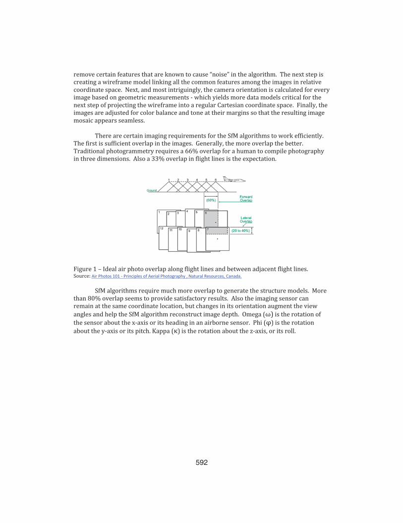
There are certain imaging requirements for the SfM algorithms to work efficiently. The first is sufficient overlap in the images. Generally, the more overlap the better. Traditional photogrammetry requires a 66% overlap for a human to compile photography in three dimensions. Also a 33% overlap in flight lines is the expectation.
Figure 1 – Ideal air photo overlap along flight lines and between adjacent flight lines. Source: Air Photos 101 - Principles of Aerial Photography , Natural Resources, Canada.
SfM algorithms require much more overlap to generate the structure models. More than 80% overlap seems to provide satisfactory results. Also the imaging sensor can remain at the same coordinate location, but changes in its orientation augment the view angles and help the SfM algorithm reconstruct image depth. Omega (ω) is the rotation of the sensor about the x-axis or its heading in an airborne sensor. Phi (φ) is the rotation about the y-axis or its pitch. Kappa (κ) is the rotation about the z-axis, or its roll.
593
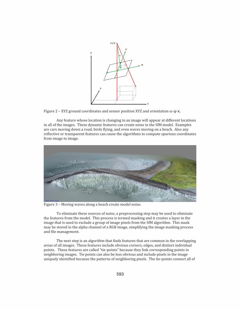
Figure 2 – XYZ ground coordinates and sensor position XYZ and orientation ω φ κ.
Any feature whose location is changing in an image will appear at different locations in all of the images. These dynamic features can create noise in the SfM model. Examples are cars moving down a road, birds flying, and even waves moving on a beach. Also any reflective or transparent features can cause the algorithms to compute spurious coordinates from image to image.
Figure 3 – Moving waves along a beach create model noise.
To eliminate these sources of noise, a preprocessing step may be used to eliminate the features from the model. This process is termed masking and it creates a layer in the image that is used to exclude a group of image pixels from the SfM algorithm. This mask may be stored in the alpha channel of a RGB image, simplifying the image masking process and file management.
The next step is an algorithm that finds features that are common in the overlapping areas of all images. These features include obvious corners, edges, and distinct individual points. These features are called “tie-points” because they link corresponding points in neighboring images. Tie points can also be less obvious and include pixels in the image uniquely identified because the patterns of neighboring pixels. The tie-points connect all of
594
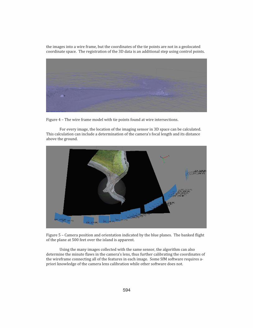
the images into a wire frame, but the coordinates of the tie points are not in a geolocated coordinate space. The registration of the 3D data is an additional step using control points.
Figure 4 – The wire frame model with tie points found at wire intersections.
For every image, the location of the imaging sensor in 3D space can be calculated. This calculation can include a determination of the camera’s focal length and its distance above the ground.
Figure 5 – Camera position and orientation indicated by the blue planes. The banked flight of the plane at 500 feet over the island is apparent.
Using the many images collected with the same sensor, the algorithm can also determine the minute flaws in the camera’s lens, thus further calibrating the coordinates of the wireframe connecting all of the features in each image. Some SfM software requires a-priori knowledge of the camera lens calibration while other software does not.

595
Next is the structure-from-motion algorithm. SfM allows the modeling of the three-dimensional features by considering how the differing camera view angles create differing 3D relief. In the case of many redundant, overlapping images, these minute changes in view angles allow a refinement to the 3D depth field. This depth field when viewed from changing camera locations utilizes motion-parallax, which generates a motion-field for all of the features. It is this depth field that contains the motion signals of every feature that appears to move with the varying perspective of every image.
This apparent feature motion based on varying view angles allows for the trajectory of the features to be calculated. This yields a kinematic (4D) depth field that includes the sensor location, feature location, and apparent motion with every changing view angle. The kinematic depth field is then reduced to the simpler structural 3D depth field.
Figure 6 – Three dimensional photo model of a gravel quarry.
A wireframe of the surface is the result. This wireframe is called a digital surface model (DSM) as it contains the coordinates for feature heights, including buildings, trees, cars, etc. A DSM is typically filtered to generate a digital elevation model (DEM), a process that removes elevation data for buildings, trees, cars, etc.
596
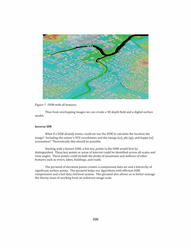
Figure 7 –DSM with all features.
Thus from overlapping images we can create a 3D depth field and a digital surface model.
Inverse SfM
What if a DSM already exists; could we use the DSM to calculate the location the image? Including the sensor’s XYZ coordinates and the omega (ω), phi (φ), and kappa (κ) orientation? Theoretically this should be possible.
Starting with a known DSM, a few key points in the DSM would first be distinguished. These key points or areas of interest could be identified across all scales and view angles. These points could include the peaks of mountains and millions of other features such as rivers, lakes, buildings, and roads.
The pyramid of elevation points creates a compressed data set and a hierarchy of significant surface points. The pyramid helps our algorithms with efficient DSM compression and a fast data retrieval system. The pyramid also allows us to better manage the thorny issue of working from an unknown image scale.

597
Figure 8 - Pyramid of DSM elevation data
Then a second pyramid of significant points is extracted from the image. Like the pyramid of the DSM, the pyramid of the image assigns a hierarchy that we will use to match the image against the DSM.
Figure 9 – Pyramid of image data.
It is then possible to overlay the image pyramid on the DSM pyramid and determine the quality of its “fit.” Using a similarity algorithm, we can exhaustively compare where the image pyramid best fits the DSM pyramid. When we find a close match between the two data sets, we can then zoom into the higher resolution data held in the respective pyramids. If the pyramids continue to match, we note the correlation between the data sets and then try to match at the highest resolution. Computational efficiencies in the fitting process can be easily gained using parallel processing methods implemented with multi-core graphical processing units.
When the image is successfully matched to the DSM, we can then derive the coordinates and orientation of the airborne sensor.
598
Summary
We offer an interesting research topic that permits the geolocation and orientation of a satellite or unmanned aerial system. This approach requires a-priori understanding of the digital surface model that a single or multiple images are to be referenced against. It is this registration process that yields the sensor’s coordinates as well orientation information.
Thus we can advance the image navigation and registration goals of the American Astronautical Society. This technology seems most applicable to unmanned aerial systems. Applications include tracking UAS where satellite navigation sensors (i.e. GPS) are unavailable. Obvious uses include the use with planned unmanned aviation systems for imaging Mars because a DSM is already developed and there is no positioning or navigation service like GPS. Our method could also serve as a backup positioning and orientation system when traditional GPS and inertial navigation systems may not be functional.
References
1. Burt, P. and Adelson, E.H., "A Multiresolution Spline with Application to Image
Mosaics", ACM Transactions on Graphics, 2(4):217-236, 1983
2. Hartley, R.I. and Zisserman, A., "Multiple View Geometry in Computer Vision", Cambridge University Press, ISBN: 0521623049, 2000
3. Kwan, Kenneth. “Image Pyramids and Blending”, Computational Photography, 2005
4. Lindeberg, T., "Feature detection with automatic scale selection", International
Journal of Computer Vision, 30, 2, pp 77–116, 1998
5. Lowe, D. G., “Distinctive Image Features from Scale-Invariant Keypoints”, International Journal of Computer Vision, 60, 2, pp. 91-110, 2004
6. Mikolajczyk, K. and Schmid, C., "A performance evaluation of local descriptors", IEEE
Transactions on Pattern Analysis and Machine Intelligence, 10, 27, pp 1615--1630, 2005
7. Shi, J. and Tomasi, C., "Good Features to Track", 9th IEEE Conference on Computer
Vision and Pattern Recognition, 1994
8. Triggs, B., "Autocalibration from Planar Scenes", European Conference on Computer Vision", 1998