aalto university school of engineering department of
TRANSCRIPT

Aalto University
School of Engineering
Department of Engineering Design and Production
Madeleine Bernas
PRODUCTIZATION OF A HIGH-SPEED SOLID ROTOR INDUCTION
MOTOR PROTOTYPE
Thesis submitted in partial fulfilment of the requirements for the degree of
Master of Science in Technology
Espoo, September 8, 2014
Supervisor: Professor Kalevi Ekman
Advisor: Jouni Ikäheimo, D.Sc. (Tech.)

Aalto University, P.O. BOX 11000, 00076 AALTO
www.aalto.fi
Abstract of master's thesis
ii
Author Madeleine Bernas
Title of thesis Productization of a high-speed solid rotor induction motor prototype
Department Engineering Design and Production
Professorship Machine Design Code of professorship Kon-41
Thesis supervisor Professor Kalevi Ekman
Thesis advisor Jouni Ikäheimo, D.Sc. (Tech.)
Date 8.9.2014 Number of pages
xiii + 82 (95)
Language English
Abstract
Productization is the art of developing a customized product, service or prototype into a
standardized marketable and commercialized product. In this thesis a high-speed induction motor
prototype is designed for manufacturing. The motor has an output power of 86 kW, rotational
speed of 21000 rpm and IEC frame size 160. The motor has a copper coated solid rotor concept,
hybrid bearings and a totally enclosed air cooling system.
High-speed motor systems provide advantages as improvement of over-all efficiency and
reliability in comparison to conventional systems by eliminating the gear box normally used for
applications requiring high-speed. In the literature study mechanical restrictions and design
considerations due to high rotational speed and centrifugal forces on machine elements are
reviewed. Different machine elements are presented as alternatives for high-speed motor
components.
To construct a profitable product from manufacturing point of view a concurrent engineering
philosophy and DFMA method is adopted. The system of hybrid bearings was retained and the
bearing support parts design was reconstructed by reconsidering necessity of the tolerances and
altering unnecessarily tight tolerances. It was decided that the bearing end shields and the motor
frame foot should be incorporated into one part and produced by casting iron in serial production.
Prototype evaluation concludes that a standard stator frame can be used and several rotor
concepts were evaluated.
The potential for reducing the manufacturing costs of the prototype motor are substantial.
However, regarding the rotor concepts more development needs to be done to ensure a functional
rotor concept.
Keywords High-speed technology, electric motors, productization, Concurrent Engineering,
DFMA, dimensional and geometrical tolerancing

Aalto-yliopisto, PL 11000, 00076 AALTO
www.aalto.fi
Diplomityön tiivistelmä
iii
Tekijä Madeleine Bernas
Työn nimi Suurnopeusmoottorin prototyypin tuotteistaminen sarjatuotantoon
Laitos Koneenrakennustekniikan laitos
Professuuri Koneensuunnittelu Professuurikoodi Kon-41
Työn valvoja Professori Kalevi Ekman
Työn ohjaaja(t) Tekniikan tohtori Jouni Ikäheimo
Päivämäärä 8.9.2014 Sivumäärä xiii + 82 (95) Kieli Englanti
Tiivistelmä
Työn tavoitteena oli tuotteistaa suurnopeussähkömoottorin prototyyppi sarjatuotantoa varten.
Lähtökohteena oli 86kW:n suurnopeusmoottori, jonka pyörimisnopeus on 21000 r/min ja IEC
runkokoko 160. Moottorilla on kuparipinnoitettu massiiviroottori roottorikonseptina,
hybridilaakereita ja ilmajäähdytys.
Suurnopeusteknologia mahdollistaa paremman kokonaishyötysuhteen ja kestävämmän
järjestelmän poistamalla perinteisesti käytetty vaihteisto suurta pyörimisnopeutta vaativissa
sovelluksissa. Suuri pyörimisnopeus ja keskipakovoimien vaikutus suurnopeusmoottorissa
aiheuttaa mekaanisia rajoituksia sekä erilliskomponenttien tarvetta. Kirjallisuustutkimuksessa
esitellään eri komponenttivaihtoehtoja suurnopeusmoottorin kone-elimistöön.
Tuotteistamisprojektissa käytetään rinnakkaissuunnittelun ja DFMA:n periaatteita.
Laakerointiosien toleranssien tarkkuus sekä roottorikonsepti on arvioitu uudestaan ja laakerikilvet
ovat yhdistetty staattorirungon jalkaan. Standardistaattorirunko sekä alunperäiset hybridilaakerit
soveltuvat käytettäväksi sarjatuotantomoottorissa prototyyppimoottorin evaluoinnin mukaan.
Moottorin sarjatuotannon kustannukset ovat merkittävästi pienempiä verrattuna
prototyyppimoottoriin tuotantokustannuksiin, mutta tarvitaan kuitenkin lisätuotekehitystä
saavuttaakseen kannattavan hintalaatusuhteen.
Avainsanat Suurnopeustekniikka, sähkömoottori, tuotteistaminen, rinnakkaissuunnittelu,
DFMA, mitta- ja geometrinen tolerointi

iv
ACKNOWLEDGEMENTS
The work for this Master’s thesis was carried out in ABB Oy, Motors and Generators
R&D unit in Vaasa, Finland during the fall of 2013. I would like to express my
gratitude for everyone that have helped and supported me during the writing of this
thesis.
I would specially like to thank my advisor on behalf of ABB, technology manager D.Sc.
Jouni Ikäheimo, for an interesting and challenging subject and for all good ideas during
the project. The supervisor of this thesis was Professor Kalevi Ekman to whom I want to
express my gratitude for good advice during the working process. I would like to thank
production manager Marko Halonen at Protoshop for the possibility to interview him
about tolerances in the manufacturing process. I would like to thank M.Sc. Ville Kivelä
for advice about rotor alternatives and M.Sc. Jouni Turunen for advice about
mechanical design. I would also like to thank the staff at Motors and Generators for
their helpfulness.
Last but not least I would like to thank my family and friends; you have been great
motivation and encouragement for me, without your support this thesis would not have
been possible.
Espoo, September 8, 2014
Madeleine Bernas

v
TABLE OF CONTENTS
ABSTRACT .................................................................................................................... ii
TIIVISTELMÄ .............................................................................................................. iii
ACKNOWLEDGEMENTS .......................................................................................... iv
TABLE OF CONTENTS ............................................................................................... v
LIST OF SYMBOLS ................................................................................................... viii
LIST OF ABBREVIATIONS ........................................................................................ x
LIST OF FIGURES ....................................................................................................... xi
LIST OF TABLES ....................................................................................................... xiii
LITERATURE STUDY ................................................................................................. 1
1 INTRODUCTION ................................................................................................. 2
1.1 BACKGROUND ........................................................................................... 2
1.2 RESEARCH OBJECTIVES .......................................................................... 3
1.3 RESEARCH SCOPE AND LIMITATIONS ................................................ 3
1.4 RESEARCH METHODS .............................................................................. 3
1.5 THESIS OUTLINE ....................................................................................... 4
2 HIGH-SPEED TECHNOLOGY ......................................................................... 5
2.1 INTRODUCTION TO HIGH-SPEED TECHNOLOGY .............................. 5
2.2 HIGH-SPEED SYSTEMS ............................................................................. 5
2.3 ADVANTAGES OF HIGH SPEED SYSTEMS ........................................... 6
3 HIGH-SPEED MOTORS ..................................................................................... 9
3.1 HIGH-SPEED MOTORS IN GENERAL ..................................................... 9
3.2 DESIGN CONSIDERATIONS FOR HIGH-SPEED MOTORS .................. 9
3.2.1 ROTOR DIAMETER ...................................................................... 10
3.2.2 ROTOR LENGTH ........................................................................... 12
3.3 INDUCTION ROTORS .............................................................................. 13
3.2.3 LAMINATED INDUCTION ROTORS .......................................... 13
3.2.4 SOLID ROTORS ............................................................................. 14
3.4 SYNCHRONOUS ROTORS ...................................................................... 18
vi
3.2.5 PERMANENT MAGNET ROTORS .............................................. 18
3.2.6 RELUCTANCE ROTORS .............................................................. 19
3.3 STATOR ...................................................................................................... 20
3.3.1 AIR GAP AND SLOT OPENING .................................................. 21
3.4 LOSSES AND COOLING OF HIGH-SPEED MOTORS .......................... 22
3.5 HIGH-SPEED BEARINGS ......................................................................... 24
3.5.1 ACTIVE MAGNET BEARINGS .................................................... 25
3.5.2 GAS FOIL BEARINGS ................................................................... 26
3.5.3 HYBRID CERAMIC BEARINGS .................................................. 27
4 DESIGN THEORY AND PRODUCTIVITY DRIVERS ................................ 29
4.1 GENERAL PRODUCT DEVELOPMENT PROCESS .............................. 29
4.2 CONCURRENT ENGINEERING .............................................................. 29
4.3 DESIGN FOR MANUFACTURING AND ASSEMBLY .......................... 31
4.3.1 ADVANTAGES OF DFMA ............................................................ 33
4.3.2 DFMA GUIDELINES ..................................................................... 33
4.3.3 THE DFM PROCESS ...................................................................... 34
4.3.4 ESTIMATION OF MANUFACTURING COSTS ......................... 36
4.3.5 CONSIDERING DFM IMPACT ON OTHER FACTORS ............. 37
4.4 TOLERANCES ........................................................................................... 38
4.4.1 DIMENSIONAL TOLERANCING ................................................ 38
4.4.2 GEOMETRICAL TOLERANCING ............................................... 39
4.4.3 GENERAL TOLERANCES ............................................................ 40
4.4.4 TOLERANCE ACCUMULATION ................................................ 40
4.4.5 TOLERANCES AND DFM ............................................................ 42
4.4.6 TOLERANCES AND QUALITY ................................................... 43
4.4.7 OFFSET SOLIDS THEORY ........................................................... 44
DESIGN PART ............................................................................................................. 46
5 INTRODUCTION ............................................................................................... 47
5.1 PROJECT DEFINITION ............................................................................. 47
5.2 HIGH-SPEED INDUCTION PROTOTYPE MOTOR ............................... 47
5.3 COST ESTIMATION .................................................................................. 49

vii
5.3.1 PROTOTYPE MOTOR ................................................................... 49
5.3.2 STANDARD MOTOR .................................................................... 50
6 ROTOR ................................................................................................................ 52
6.1 PROTYPE ROTOR ..................................................................................... 52
6.2 ROTOR CONCEPTS .................................................................................. 54
7 BEARING ARRANGEMENT ........................................................................... 61
7.1.1 BEARING TYPE USED ................................................................. 61
7.1.2 INNER BEARING COVERS .......................................................... 62
7.1.3 OUTER BEARING COVERS ......................................................... 64
8 END SHIELDS .................................................................................................... 67
9 STATOR .............................................................................................................. 70
9.1 STATOR FRAME ....................................................................................... 70
10 DISCUSSION ...................................................................................................... 72
10.1 SUMMARY OF RESULTS ........................................................................ 72
10.2 DISCUSSION .............................................................................................. 74
10.3 CONCLUSION ........................................................................................... 75
10.4 RECOMMENDATIONS FOR FURTHER WORK ................................... 76
BIBLIOGRAPHY ......................................................................................................... 78

viii
LIST OF SYMBOLS
A Area
C Constant
D Diameter
E Young’s modulus
I Moment of inertia
K Constant estimated from quality loss of a part
k Ratio between critical frequency and nominal angular velocity
ksafe Safety factor for mechanical stress
L(Y) Quality loss for dimension Y
Lr Rotor length
n Rotational speed
P Power
PCu Ohmic loss not depending on frequency
PCu,r Rotor copper losses
PCu,s Stator copper losses
Pexc Excess losses
PFe,r Rotor iron losses
PFe,s Stator iron losses
Pfr,bearings Bearing friction loss
Pfr,total Total friction loss
Pin Input power
PL Total loss
Pout Output power
Pδ Air gap power
pe Eddy-current loss coefficient
pf Friction loss coefficient
ph Hysteresis loss coefficient
r Radius
T Torque
Vrt Rotor volume
v Velocity

ix
X Dimension
Y Dimension
σ Maxwell’s stress tensor
σmax Maximum stress allowed
σtan Tangential stress
ν Poisson’s coefficient
ρ Mass density
Ω Mechanical angular velocity
ΩC Critical mechanical angular velocity
Ωn Nominal mechanical angular velocity

x
LIST OF ABBREVIATIONS
AMB Active Magnetic Bearing
CE Concurrent Engineering
DFA Design for Assembly
DFM Design for Manufacturing
DFMA Design for Manufacture and Assemly
DFX Design for X
emf Electromotive force
HIP Hot isostatic pressing
IM Induction motor
IPM Interior Permanent Magnet
mmf Magnetomotive force
PM Permanent magnet
rpm Revolutions per minute
SPM Surface-mounted Permanent Magnet
TEFC Totally enclosed fan cooled
TEWAC Totally enclosed water to air cooled

xi
LIST OF FIGURES
Figure 1. High-speed induction motor used in an automotive environment ................... 6
Figure 2. Advantages of using a high-speed system over a conventional system include
reduction of system mass and volume .............................................................................. 7
Figure 3. Mechanical and thermal constraints set on the rotor. ..................................... 10
Figure 4. Maximum power versus rotational speed....................................................... 14
Figure 5. Solid-rotor designs: a) smooth solid rotor, b) axially slitted solid rotor, c)
axially slitted solid rotor with end-ring structure, d) solid rotor with deep copper bars
and end rings (squirrel cage), e) smooth solid rotor with coating .................................. 16
Figure 6. Cross section of three main synchronous motor types. .................................. 18
Figure 7. Example of Permanent Magnet rotor construction ........................................ 19
Figure 8. Power losses of an induction motor. .............................................................. 23
Figure 9. Overview of an AMB system ......................................................................... 26
Figure 10. Bump type foil bearing ................................................................................. 27
Figure 11. Generic product development process. ........................................................ 29
Figure 12. Concurrent Engineering; a nonlinear design approach. ............................... 30
Figure 13. Engaged cost by decisions and evolution of expenses during product life
cycle ................................................................................................................................ 31
Figure 14. The DFM process ......................................................................................... 35
Figure 15. Categorization of manufacturing costs ......................................................... 36
Figure 16. Important factors to be optimized in the tolerancing process. .................... 38
Figure 17. Size (dimension) and circularity (geometrical) tolerances. ......................... 40
Figure 18. Tolerance Accumulation in gear pump assembly ........................................ 41
Figure 19. Cost as function of process........................................................................... 42
Figure 20. Interpretation of Quality and Tolerances according to a. Conventional b.
Taguchi. .......................................................................................................................... 43
Figure 21. Geometric tolerancing by offset zones. ........................................................ 45
Figure 22. Explosion figure of the prototype motor. ..................................................... 47
Figure 23. Prototype motor cross section and cooling topology. .................................. 49
Figure 24. Cost breakdown structure for the prototype motor. ..................................... 49
Figure 25. Cost breakdown structure for materials used for prototype motor............... 50
Figure 26. Cost breakdown structure for materials used motor of similar size. ............ 51
Figure 27. Cost breakdown structure for materials used for motor with similar output
value. .............................................................................................................................. 51
Figure 28. Prototype rotor copper coated by explosion welding. .................................. 52

xii
Figure 29. Prototype motor rotor drawing displaying main dimensions and toleranced
dimensions of significance. ............................................................................................ 53
Figure 30. N-end of shaft, the bearing fit tolerances are subject for altering but not the
geometrical tolerances. ................................................................................................... 53
Figure 31. The objectives tree for design of rotor structure. ......................................... 54
Figure 32. Number of process stages for the different rotor alternatives. ..................... 55
Figure 33. Process stages for the different rotor alternatives. ....................................... 55
Figure 34. Laminated squirrel cage rotor. ..................................................................... 57
Figure 35. Solid rotor. .................................................................................................... 58
Figure 36. Copper coated solid rotor. ........................................................................... 58
Figure 37. Slitted solid rotor. ......................................................................................... 59
Figure 38. Assembly drawing of prototype motor......................................................... 61
Figure 39. Hybrid bearing type used in prototype motor. ............................................. 62
Figure 40. Inner bearing covers. .................................................................................... 63
Figure 41. Measurement drawing for prototype motor inner bearing covers with a.
original tolerances and b. altered tolerances. .................................................................. 64
Figure 42. Outer bearing cover for non-drive end. ........................................................ 65
Figure 43. Outer bearing cover for drive end. ............................................................... 65
Figure 44. Prototype end shields for a. non-drive and b. drive end. .............................. 67
Figure 45. Assembled prototype motor. ........................................................................ 68
Figure 46. Drive end shield and motor feet incorporated. ............................................. 68
Figure 47. Measurement drawing for a. prototype motor bearing end shields b. end
shields with altered tolerances. ....................................................................................... 69
Figure 48. Stator sheets of the prototype motor. ........................................................... 70
Figure 49. Stator frame for prototype motor. ................................................................ 71

xiii
LIST OF TABLES
Table 1. Design specifications for the solid-rotor induction prototype motor. .............. 48
Table 2. Pro/Con chart for different rotor types. ........................................................... 56
Table 3. Pro/Con chart for different copper coating methods. ...................................... 59
Table 4. Cost cutting potential and alternations necessary for the different machine
elements. ......................................................................................................................... 76

1
LITERATURE STUDY

2
1 INTRODUCTION
1.1 BACKGROUND
There is a clearly growing demand for cost efficient, reliable high-speed motors in the
low voltage motor market. The actual market trend is towards continuously improving
efficiency and power density combined with reduced production costs. Considering
motor design trends the direction is to higher and higher rotational speeds with specific
interest in direct-drive solutions. (Boglietti et al., 2010)
High-speed technology has been rapidly developing during the recent years and offer
several advantages in comparison to conventional methods to achieve high rotational
speed and shaft power. High-speed motors are more efficient, demand less maintenance
and space than traditional gear systems. High-speed motors also offer higher power
density and decreased installation space for higher power.
The construction of high-speed motors differs from conventional induction motors since
the components of high-speed motors need to withstand greater centrifugal forces
leading to high mechanical stresses on rotating parts. High quality motor elements and
special design methods need to be used in high-speed motors to avoid failure and
achieve an acceptable life expectancy.
Solid-rotor induction motors are mechanically very stable and therefore a good option
for high-speed machines. Other machine constructions, like permanent magnet motors,
offer better electromagnetic characteristics. (Arkkio, Jokinen & Lantto, 2005) However
in comparison to other machine types, induction motors offer qualities as
inexpensiveness, easiness to manufacture and safety. (Pellegrino et al., 2012)
The high-speed market is still quite small and highly efficient production lines do not
exist. (Arkkio, Jokinen & Lantto, 2005) This would be the next step in the development.

3
1.2 RESEARCH OBJECTIVES
An existing motor prototype is to be further developed for serial production. The
prototype motor is a high-speed induction motor with rotational speed of 21 krpm and
output power of 86kW. The machine has a solid rotor with copper coating by explosion
welding and hybrid ceramic bearings. Internal air cooling and forced oil lubrication is
applied to the machine. The production cost need to be optimized; prototype needs to be
designed for manufacturing. The main research problem of this study is:
Can we construct a product which is profitable from a view of manufacturing
technology and satisfies quality demands?
The main objective can be derived from the research problem; to achieve a serial
production cost that is sufficient to be able to compete on the high-speed device market
against conventional motors with gear boxes.
1.3 RESEARCH SCOPE AND LIMITATIONS
In this research the scope is on the mechanical design of high-speed induction motors
with solid rotors. The focus lies on further product development of a high-speed
induction motor prototype for serial production. Three main types of high-speed
electrical machines are used in the industry: induction machines, permanent-magnet
machines and switched-reluctance machines. In this thesis mainly high-speed induction
motors are discussed. The starting point for the project is a prototype motor, hence
motor concept design is quite clear already and design activities are restricted to system
level design and detail level design. Rotor concept however, is discussed. Only the
mechanical design aspects of the design process are covered excluding the electrical
design aspects.
1.4 RESEARCH METHODS
Research methods utilized are conducting interviews with manufacturing experts,
evaluation of possible production methods and materials, determining less strict
geometric and positional tolerances for the motor, consideration of possible design

4
alternations that would make the motor more suitable for serial production. New
prototype parts are manufactured for design evaluation and cost estimation.
1.5 THESIS OUTLINE
The remaining part of this thesis is organized as following:
- A literature part involving three chapters. Chapter 2 consists of a general brief
on high-speed systems; definition, fields of application and advantages of high-
speed technology. Chapter 3 present a general study of high-speed solid-rotor
induction motors, including the elements used in high-speed solid-rotor
induction motors and design considerations for the different machine
components. Chapter 4 examines the theory necessary for the design work;
design methodology, including general product development process, concurrent
engineering, design for manufacturing process and tolerancing.
- A design part consisting of six chapters. Chapter 5 includes project definition,
presentation of the high-speed induction motor and cost estimation by cost
breakdown structures for the prototype motor and a comparison with a standard
motor. Chapter 6 presents the rotor prototype and rotor concept alternatives.
Chapter 7 and 8 present the bearing arrangement and the end shields, including
design alternations carried out. Chapter 9 presents stator and stator frame.
Chapter 10 concludes the thesis with summary of results, discussion, conclusion
and recommendations for further work.

5
2 HIGH-SPEED TECHNOLOGY
2.1 INTRODUCTION TO HIGH-SPEED TECHNOLOGY
High-speed technology research in Finland began as collaboration between Helsinki
University of Technology (HUT, today Aalto University), Lappeenranta University of
Technology (LUT) and the Finnish Funding Agency for Technology and Innovation
(TEKES) in the 1980’s. This collaboration resulted in the first high-speed motor
prototypes in Finland. During the last three decades a great deal of research on high-
speed technology has been conducted and several high-speed technology products and
companies have been established. (Larjola, Arkkio & Pyrhönen, 2010)
The need for high speed technology comes from the fact that certain kind of load
machine need high rotational speed to perform with high efficiency; the performances
of the devices improve with speed e.g. turbo compressors. (Lähteenmäki, 2002; Antila,
1998)
2.2 HIGH-SPEED SYSTEMS
There are several definitions for the expression “high-speed”. According to Larjola,
Arkkio & Pyrhönen (2010) high-speed technology implies an arrangement where an
electrical motor or generator and a regulating load-machinery unit are connected
directly to the shaft without gear in between and where the rotational speed of the rotor
clearly exceeds 3000 rpm, typically 10 000 rpm. Oil free gas or magnet bearings or
special high-speed bearings are used in high-speed devices.
Frequency converters are used to control the speed and power of high-speed devices,
this gives full speed control for the drive. (Kolondzovski, 2010) Modern-day frequency
converters do not anymore restrict the power of a high-speed drive. The factors that
limit maximum power and speed of an electrical high-speed application are mechanical
stresses on the rotating parts as well as electrical and thermal issues that increase with
frequency. (Boglietti et al., 2010; Arkkio, Jokinen & Lantto, 2005)

6
High-speed devices are used as electromechanical converters in numerous industrial
applications such as (Boglietti et al., 2010; Antipov & Danilevich, 2007; Binder &
Schneider, 2007)
o compressors and turbochargers
o blowers
o centrifuges
o turbo-molecular vacuum pumps
o generator motor units for flywheels
o spindles for machine tools
o micro co-generation gas turbines
In Figure 1 an application environment for a high-speed induction motor is shown.
Figure 1. High-speed induction motor used in an automotive environment (Gerada et al., 2011).
2.3 ADVANTAGES OF HIGH SPEED SYSTEMS
In high-speed systems the load-machinery is, as previously mentioned, directly attached
to the shaft of the electrical machine, implying a gearbox used in traditional systems for
controlling speed is not needed. One of the main advantages of a high-speed motor is
this absence of a gearbox, in other words a direct drive. (Huppunen, 2004) Direct drive
offer multiple advantages over gears, giving reason to many of the advantages of high-
speed systems. (Boglietti et al., 2010)

7
The size of the electrical motor is determined by the size of the cooling system and the
torque according to P=2π∙n∙T; hence increasing speed and maintaining the power
constant results in lower mechanical torque. Therefore electrical high-speed motors are
rather small due to the low torque at high speed if maintaining the power constant.
(Binder & Schneider, 2007)
High-speed systems offer advantages in comparison to conventional high-speed systems
that include (Boglietti et al., 2010; Kolondzovski, 2010; Binder & Schneider, 2007):
high power density
smaller volume and mass
avoidance of mechanical transmissions
increased reliability
system efficiency increase
reduced maintenance operation costs
increased mechanical stiffness
lower noise
reduction of wear
oil free performance possibility
Advantages of direct drive in a compressor system are illustrated in Figure 2.
Figure 2. Advantages of using a high-speed system over a conventional system include reduction of system mass and
volume. (Lateb, Enon & Durantay, 2009)
High-speed operation brings multiple advantages for several technical processes such
as: smaller size for similar power rating in compressors, pumps and gas-turbines, raised

8
cutting speed in cutting and milling, reduced cutting time and improved performance
and increased stored energy in flywheels (Binder & Schneider, 2007)

9
3 HIGH-SPEED MOTORS
3.1 HIGH-SPEED MOTORS IN GENERAL
The induction motor is also the most common machine used for high-speed
applications, followed by permanent magnet and switched reluctance machines.
Induction machines are adopted in high-speed applications due to their robust rotor
structures and low maintenance. (Boglietti et al., 2010)
Rotor joule losses present in induction machines cause the motors to have lower
efficiency than other types of electrical machines. Switched Reluctance motors have the
most simple and robust rotor structures suitable for high-speed operation and Permanent
Magnet motors usually have higher power density and higher efficiency, but both motor
types have some drawbacks that could limit their use in high-speed applications.
(Boglietti et al., 2010)
3.2 DESIGN CONSIDERATIONS FOR HIGH-SPEED MOTORS
In high-speed applications mechanical aspects are of greater importance than in normal
speed machines and therefore require certain design considerations. Mechanical design
compromises stress analysis and rotordynamic analysis, involving selection of bearing
type, bearing stiffness, shaft diameter and calculation of the rigid and nonrigid body
modes of the motor. (Gerada et al., 2011)
High-speed motors are associated with many benefits but also with many problems. By
increasing speed and decreasing size, mechanical constraints and machine overheating
become main design problems. High-speed devices must sustain large mechanical stress
due to centrifugal forces, which cause tangential stress in rotating cylinders or rings.
The small machine dimensions and high fundamental frequencies fuel thermal
constraints following high losses in the rotor and in the air gap. (Gerada et al., 2011)
Figure 3 illustrates the constraints on a high-speed machine solid rotor.

10
Figure 3. Mechanical and thermal constraints set on the rotor. (Lähteenmäki, 2002)
These constraints affect the choice of material as well as rotor length/diameter ratio and
the choice of cooling system. The mechanical constraints often dominate rotor design
since they give limits to the size of the rotor and set requirements for manufacturing
techniques. Mechanical as well as thermal constraints are often affected by the end
application. (Lähteenmäki, 2002)
Typical design features for high speed motors are low iron magnetic flux density values
to reduce losses as well as using laminations. The material need to be in safe thermal
operating limits and mechanical analysis of material properties as a function of
temperature needs to be done to ensure safe operation. (Gerada et al., 2011) The high
frequency supply of the motor needs an inverter with low losses. There is also a
problem with bearing lifecycle to be solved and the machine mounting needs exact
alignment. (Larsson et al., 2003)
3.2.1 ROTOR DIAMETER
The rotor plays an important role in all motor design since the rotor is the interface for
transferring mechanical power from the electrical machine to the mechanical load.
Normally, the bigger the mechanical torque to be transferred the bigger is the shaft
diameter, the torque developed by the electrical machine is proportional to the rotor
diameter. (Boglietti et al., 2010) The relation between the torque and the volume can be
calculated with help of the electromagnetic rotor surface tangential stress : (Aho,
2007)

11
(3.2.1)
The maximum rotor diameter is affected by the rotor surface tangential stress on
the rotor and the mechanical strength of the material. Increasing the diameter increases
the torque. However the centrifugal forces increase with rotor diameter and the rotor has
to withstand higher mechanical stress. The maximum tangential stress in the rotor takes
place in the center of the rotor and is dependent on mass density and circumference
speed according to (3.2). (Aho, 2007)
(3.2)
where ρ is the mass density of the material, Ω is the angular velocity of the rotor, C is a
factor that can be estimated:
(smooth homogenous cylinder) (3.3)
(cylinder with small bore) (3.4)
(thin cylinder) (3.5)
where ν is the Poisson’s coefficient for the corresponding material.
Since the formula can be written as where is the circumference
speed, therefore the term “high-speed” is not a matter of high n or , more of high v as
in surface velocity of the rotor. (Binder & Schneider, 2007)
In high-speed machine rotor design the aim is to keep the rotor external diameter as low
as possible in order to reduce the peripheral rotational speed and to avoid large
centrifugal forces acting on the rotor. Instead the rotor axial length is increased to
develop a specific mechanical torque. This also creates a reduction of the friction losses
in the air gap, which are significant losses in high-speed machines. Friction losses are
proportional to rotor axial length and function of the fourth power of the external
diameter. (Boglietti et al., 2010)
12
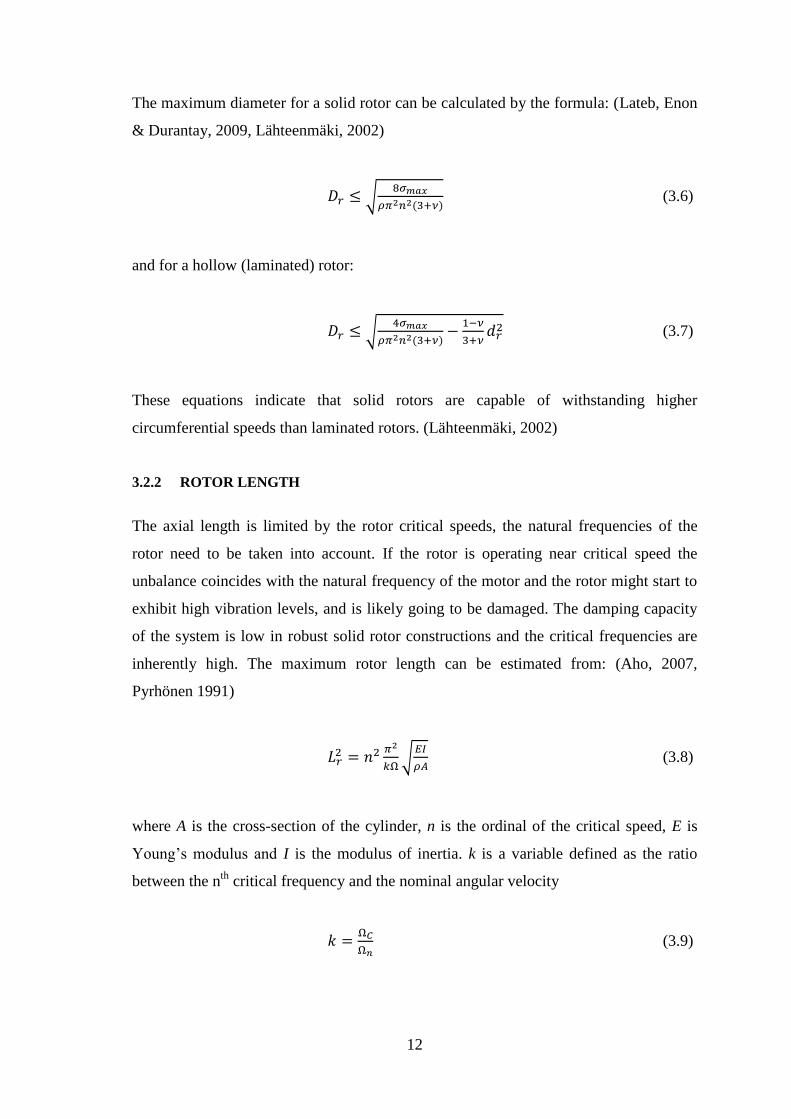
The maximum diameter for a solid rotor can be calculated by the formula: (Lateb, Enon
& Durantay, 2009, Lähteenmäki, 2002)
(3.6)
and for a hollow (laminated) rotor:
(3.7)
These equations indicate that solid rotors are capable of withstanding higher
circumferential speeds than laminated rotors. (Lähteenmäki, 2002)
3.2.2 ROTOR LENGTH
The axial length is limited by the rotor critical speeds, the natural frequencies of the
rotor need to be taken into account. If the rotor is operating near critical speed the
unbalance coincides with the natural frequency of the motor and the rotor might start to
exhibit high vibration levels, and is likely going to be damaged. The damping capacity
of the system is low in robust solid rotor constructions and the critical frequencies are
inherently high. The maximum rotor length can be estimated from: (Aho, 2007,
Pyrhönen 1991)
(3.8)
where A is the cross-section of the cylinder, n is the ordinal of the critical speed, E is
Young’s modulus and I is the modulus of inertia. k is a variable defined as the ratio
between the nth
critical frequency and the nominal angular velocity
(3.9)

13
The ratio between the rotor length Lr and the radius r can be estimated with the
following formula:
(3.10)
where ksafe is the safety factor for the maximum mechanical stress. To achieve high
speeds without vibrations, thick and short rotor constructions are preferable, and to be
absolutely sure, the first critical speed should be above the motor operating speed. High
speed machines are often operated between the first and second critical speed, and in
high-speed drive systems the rotor might pass several critical speeds during start-up,
however the critical speed must be passed by quickly and the speed range is reduced
into a narrow speed area. (Boglietti et al., 2010, Aho, 2007)
3.3 INDUCTION ROTORS
One of the most elementary types of rotating machines is an induction or an
asynchronous motor. Electric induction motors are the most common source of
mechanical power. Properties of induction motors are low cost, reliability and ease of
operation. (Lähteenmäki, 2002)
3.2.3 LAMINATED INDUCTION ROTORS
In conventional induction motors laminated rotors are used. The mechanical strength of
the electrical silicon steel in standard laminated rotors limit the surface speed to 150
m/s, at higher speeds there is a mechanical problem keeping the lamination layers
tightly attached to the shaft. Hence laminated rotors are not rigid enough for higher
speeds and more rigid rotor constructions, such as solid rotors, need to be used in high-
speed applications. (Aho, 2007)
Figure 4 displays speed limits for laminated and solid rotor types. The curves are
obtained using conventional electric and magnetic loadings. There rotors are steel rotors

14
with 700 MPa yield stress with maximum operating speed set at 20 percent below the
first critical speed. (Huppunen, 2004)
Figure 4. Maximum power versus rotational speed (Huppunen, 2004)
The rotational speed limit for the laminated rotors varies from ca. 10 000 rpm to 50 000
rpm according to Figure 4. However, this speed level might require special construction
of the rotors. The rotational speed for solid rotors varies between 20 000 rpm to 100 000
rpm. The upper speed is always set by mechanical restrictions while the output power is
defined by the thermal design of the machine. (Huppunen, 2004)
3.2.4 SOLID ROTORS
The solid rotor is ideal in the aspects of fluid dynamical and mechanical performance,
and it has very good thermal resistance. This rotor type is the strongest possible, most
stable and maintains its balance best of all rotor types. Maintaining balance and
avoiding vibrations is important to not cause damage to the bearing system. (Huppunen,
2004) Solid rotors can stand surface speeds larger than 400 m/s (Arkkio, Jokinen &
Lantto, 2005) are used for rotational speeds between 20 000-200 000 rpm and where the
rotor surface speed exceeds 150 m/s. (Saari, 1998) Solid-rotors are built with a rotor
core made of a solid single piece of ferromagnetic material. The solid rotor is an easy
and cheap alternative from a manufacturing point of view. (Aho, 2007)

15
The solid rotor construction offer several advantages such as: (Huppunen, 2004)
High mechanical stability
High thermal strength
High reliability
Easy and cheap to manufacture
Easy to achieve high chemical durability
Low noise and vibration level (if the surface is smooth)
Electrical properties of smooth solid rotors are poor due to the generation of excessive
eddy-current losses in the solid rotor surface. (Aho, 2007) The output power, efficiency
and power factor for a solid-rotor induction motor is lower than for a laminated rotor
cage induction motor. These factors can be diminished in one of the following ways:
(Huppunen, 2004)
a) Constructing the solid rotor of a material with a small ratio of magnetic
permeability to electric conductivity.
b) Using axial slits to improve the magnetic flux penetration to the rotor material.
c) End-ring structure of high-conductivity material.
d) Embed a squirrel cage in the rotor material.
e) Coating the rotor.
These alternatives are illustrated in Figure 5.

16
Figure 5. Solid-rotor designs: a) smooth solid rotor, b) axially slitted solid rotor, c) axially slitted solid rotor with
end-ring structure, d) solid rotor with deep copper bars and end rings (squirrel cage), e) smooth solid rotor with
coating. (Huppunen, 2004)
The easiest performance improvement method seen in Figure 5 b) is slitting the cross-
section of the rotor, to achieve better flux penetration into the rotor. Slitting the rotor

17
decreases low-frequency impedance in the rotor, therefore more torque is produced.
Slitting also increases the high-frequency surface impedance on the rotor, decreasing
eddy-current loss. The disadvantage of axial slitting is the fact that the ruggedness of the
solid rotor is to a part lost and at very high speeds the friction between the rotor and air
is remarkably increased. The slitting increases the cooling of the rotor because of
increased cooling surface, so increased friction might be justified by this in medium
speed motors (10 krpm) but not high speed motors. (Aho, 2007)
End rings, seen in Figure 5 c), could be used to reduce the rotor impedance and
improve the torque and power factor of the machine. Very precise manufacturing is
required to produce this kind of rotor. The copper end rings must have a tight galvanic
connection to the solid rotor end. If there is any gap between the rotor base material and
the end rings, the end ring effect will be lost and there might be dangerous vibrations at
high-speed. This rotor type has lower ruggedness and cannot be used with an aggressive
medium. (Uzhegov, 2012)
A solid rotor type with copper squirrel cage is shown in Figure 5 d). This type of rotor
has the best performance, but the squirrel cage with deep copper bars is difficult to
produce. The mechanical ruggedness can suffer from the construction and also this rotor
type cannot be used in an aggressive medium. (Uzhegov, 2012)
As seen in Figure 5 e) the outer layer of the rotor can be laminated with high-
conductive low permeability material (like copper) to reduce the eddy current losses in
the surface. The coating material acts as a mirror for high-frequency air gap harmonics
and does not let high-frequency harmonics penetrate through the laminated layer.
Copper coating is good from an electromagnetic performance point of view, however it
should be noted that producing a copper coating on a solid rotor is expensive. Another
method is to coat the rotor with high-resistive ferromagnetic material. The idea in this
approach is that the coating should increase the rotor surface impedance and dampens
the harmonic fields before they reach the rotor core material and create losses. If using
this method the coating might be welded onto the rotor, which would boost the rigidity
of for instance a solid slitted rotor. (Aho, 2007)

18
3.4 SYNCHRONOUS ROTORS
The synchronous motor operates as the name suggests at a synchronous speed
determined by the stator excitation frequency. (Haataja, 2003) There are three main
types of synchronous rotors, these are depicted in Figure 6.
Figure 6. Cross section of three main synchronous motor types. (Meier, 2002)
Figure 6 a) shows the cross section of a surface mounted PM. Machine. Permanent
magnets are fixed to an iron rotor core, normally glued to the rotor surface and
bandaged with e.g. glass-fibre to ensure mechanical strength standing centrifugal forces.
Figure 6 b) shows a possible design of an interior permanent magnet motor. The
magnets are buried into the rotor core. Setting the magnets inside improves the
mechanical stability of the rotor and the magnetic protection. Figure 6 c) shows a cross
section of a reluctance rotor, without permanent magnets, the reluctance motor only
produces reluctance torque. (Meier, 2002)
3.2.5 PERMANENT MAGNET ROTORS
Permanent magnet motors differ from induction motors by the fact that the magnetic
field is produced by the rotor and not the stator windings. The magnetic field is
produced by the permanent magnets in the rotor and arranged to drive flux across the air
gap in alternating directions into and out of the rotor surface. Constant torque is
produced when the pattern of flux on the rotor revolves in perfect synchrony with the
rotating field produced by the stator. (Beer et al., 2006)

19
Permanent magnet motors can be of the types surface-mounted PM (SPM) and interior
PM (IPM). The SPM motor has a simpler construction and shorter end connection but
has eddy-current loss at high-speed, very limited transient overload power, and has high
uncontrolled generator voltage. The IPM motor has better performance, but is more
complicated to manufacture. (Pellegrino et al., 2012)
Internal permanent magnet rotor construction consists of a shaft of solid steel with
permanent magnets mounted onto the shaft. On and between the permanent magnets is
an aluminium screen to reduce eddy-current losses. To support the system from
centrifugal forces a carbon fibre sleeve or retaining ring is used. (Arkkio, Jokinen &
Lantto, 2005) An example of a permanent rotor construction is depicted in Figure 7.
Figure 7. Example of Permanent Magnet rotor construction. (Arkkio, Jokinen & Lantto, 2005)
Permanent magnet (PM) motors are considered to have higher efficiency and higher
torque in comparison to induction motors. However, mechanical constraints limit the
use of PM machines to applications with surface speeds under 250 m/s. When designing
PMs the eddy-current loss of the rotor and permanent magnets need to be minimized.
These losses easily induce temperature rise higher than allowed in the permanent
magnets. (Arkkio, Jokinen & Lantto, 2005)
3.2.6 RELUCTANCE ROTORS
The electromagnetic torque for synchronous reluctance motors only consists of
reluctance torque. The principle for producing the torque is using reluctance differences.

20
(Haataja, 2003) The reluctance motor is constructed based on the principle that a
magnetic field will exert a force to decrease the resistance to the flow of magnetic flux.
The reluctance rotors do not produce their own magnetic field, rather providing a
position dependent reluctance known as magnetic saliency. There are two types of
reluctance motors; the switched reluctance motor utilizing a stator that also possesses
magnetic saliency and the synchronous reluctance machine that contains a similar stator
to that used in an AC induction motor. (Hortman, 2004)
3.3 STATOR
The most important design aspect in the design of high-speed rotor is perhaps having a
smooth sinusoidal air gap flux at the surface of the rotor. If the air gap flux is not
smooth the harmonic components will induce a considerable amount of loss on the
rotor, especially in solid rotors. (Lähteenmäki, 2002)
There are currently two approaches for reducing the harmonic losses. One approach is
making the magnetomotive force (mmf) produced by the stator windings as sinusoidal
as possible, aiming to reduce the winding harmonics. Another approach is making the
air gap permeance as smooth as possible. Both approaches can be applied at the same
time to reduce the harmonic content of the air gap flux. (Lähteenmäki, 2002)
Smoother mmf waveform can be achieved by an increased number of slots or by using a
chorded two layer winding instead of one that is used in conventional motors. As a
ground rule, the more slots the better, if they do not become too small and there is room
enough for the teeth. This reduces the losses in the rotor side, and the reduction is
usually enough to cover the increase of iron loss at the stator side that follows the
increased slot number. (Lähteenmäki, 2002)
The stator design can also be improved by using a short pitch double layer winding. The
pitching decreases the harmonic contents of the mmf and the air gap flux efficiently.
However, main voltage insulation is needed between two phases in the same slot,
leading to a decrease of the slot filling factor. The winding factor for the magnetomotive
force is also reduced slightly. (Lähteenmäki, 2002)

21
The high frequency currents and stray flux may cause skin effect and eddy-current loss
in the windings. This can be avoided by using random wound windings, consisting of
thin conductors. Another design problem is the fact that rotor dynamics often suggest a
short but wide rotor construction, hence the same for stator. For a two pole motor this
results in higher ohmic loss and leakage inductance due to long end windings. A four
pole motor would be better, but this would mean double supply frequency, higher iron
loss, increased skin effect and higher switching loss for the inverter. A design trade off
decision has to be made. (Lähteenmäki, 2002)
Stator design is especially important in solid rotor machines due to the fact that
harmonic eddy current losses are a significant problem in solid rotor machines than
compared to laminated-rotor machines. Normally, harmonic eddy current losses make
up only 2-5% of total losses in laminated rotor machines. However, in the case of solid
rotor machines harmonic losses normally constitute 10% of total losses and can reach
up to 50% if the motor is not designed properly. High efficiency of the solid-rotor
induction motor can be reached if the stator losses and the harmonics in the air-gap are
kept low. (Huppunen, 2004)
3.3.1 AIR GAP AND SLOT OPENING
The air gap flux at the rotor side might be the most important single parameter in the
whole design of a high-speed motor. The size of the air gap affects the air gap
permeance variation a lot and in addition to decreasing winding harmonics the
permeance harmonics need to be reduced. (Lähteenmäki, 2002)
For an induction motor a long air gap is a problem since the rotor has to be magnetized
from the stator side. A long air gap means high magnetization current, increased ohmic
losses in stator windings and lower power factor. On the other hand a long air gap is
needed to dampen the harmonic components of the magnetic flux on the rotor surface.
The increased need of magnetization can be seen as compensated for by the reduction in
rotor loss. (Lähteenmäki, 2002)

22
The selection of the air gap is based on balancing the loss components so that total loss
is minimized. The cooling is also influenced by the size of the air gap if the flow is
forced through the air gap. The air gap in high-speed motors is normally larger than in
conventional induction motors, and this seems to be the solution for high-speed
applications. (Lähteenmäki, 2002)
The other way to decrease the permeance harmonics is to minimize the stator slot
opening. Magnetic or semi-magnetic slot wedges close the slot opening and smoothen
the permeance fluctuation, but there is a down side with increased leakage reactance.
(Lähteenmäki, 2002)
3.4 LOSSES AND COOLING OF HIGH-SPEED MOTORS
High-speed machines need an extremely reliable cooling system, in order to avoid stator
winding, rotor cage and bearings overheating and shaft deformations. (Boglietti et al.,
2010) The cooling system design is of equal importance as the electromagnetic design
of the motor, since the thermal rise of the motor eventually determines the output power
of the motor. (Almasi, 2012)
The cooling of a high-speed machine needs to be designed with special attention; the
power-size ratio of the machine increases as the rotational speed of the machine
increases; the power density as well as the loss density is increased. (Antila, 1998)
Figure 8 illustrates the power losses in a high-speed induction motor.

23
Figure 8. Power losses of an induction motor. (Aho, 2007)
The stator copper losses PCu and the iron losses PFe consumes some of the power
supplied to the motor, Pexc stands for excess losses in the stator. On the rotor side there
are resistive losses PCu,r and iron losses PFe,r. In addition there are mechanical losses
caused by bearings, windage and gas friction. The remaining power Pout is the value of
Pin deducted by the losses.
The distribution of the losses is different in a high-speed motor compared to a
conventional motor. The relative share of the loss components change with speed
according to the following quotient of total loss PL per output power Pout (Lähteenmäki,
2002):
(3.11)
where PCu is the ohmic loss not dependent on frequency and ph, pe and pf are the loss
coefficients for hysteresis, eddy-current and friction loss. C is a utilization factor
describing how much torque per volume unit can be taken out from the rotor of a
volume Vrt. n stands for rotational speed. According to the quotient the relative share of
ohmic losses decreases while the share of eddy-current and friction losses increases with
rotational speed. This illustrates how the losses are distributed as a function of speed,
implying that a motor design should change with rotational speed. (Lähteenmäki, 2002)

24
Since high-speed motors have high loss densities, high-speed machines need open-
circuit cooling. (Saari, 1998) In high-speed machines normally the cooling substance
flows through the motor removing the heat from interior parts. The cooling system is
usually a totally enclosed water to air cooled (TEWAC) unit. (Almasi, 2012) Totally
enclosed fan cooled (TEFC) motors are not viable for high-speed motors, since the
major part of the losses are friction and cooling losses generated in the air gap between
stator and rotor. The hot air in the air gap must be taken out. (Lähteenmäki, 2002)
The cooling system of the high-speed motor highly impacts design of the machine and
vice versa. Different coolants and cooling flow topologies can be chosen for high-speed
motors depending on the motor construction. Design selection of the motor and the
cooling system go hand in hand. For instance in some cases direct cooling of rotor is
considered troublesome and cooling of stator is utilized instead, cooling of the stator
might need axial or radial cooling ducts. Hydrogen or helium can be used as closed
circuit coolants, reducing friction loss and increasing heat transfer, while water coolant
for stator can be used for maximum performance. (Lähteenmäki, 2002)
During cooling system design for high-speed motors it is important to consider avoiding
high thermal differences in certain part of the motor, e.g. around the bearings. Another
aspect to consider while designing cooling systems for high-speed machines is the fact
that coolant flow through the air gap of the motors could generate losses due to the gas-
flow, which can reduce total motor efficiency. (Boglietti et al., 2010)
3.5 HIGH-SPEED BEARINGS
Bearings are critical components in high-speed electrical motor design. Higher
rotational speed, stiffness, precision and less noise are required from bearings used in
high-speed applications. (Boglietti et al., 2010) Bearings in high-speed technology
devices are usually oil free gas- or magnet bearings, or circulating lubrication systems.
(Larjola, Arkkio & Pyrhönen, 2010)

25
The lack of high-speed bearing technologies permitting high reliability and long lifetime
is currently limiting a successful application of ultra-high-speed drive systems. (Looser
& Kolar, 2011) Conventional roller bearings have a limited life time in high-speed
applications. Ceramic bearings are used at higher speeds; however, even these cannot
provide particularly long service life. Gas bearings are not widely used in industrial
applications, due to a number of factors. There is no readily usable design algorithm for
gas bearings, there are instability problems and it is difficult to predict dynamic
behavior. Testing the gas bearings is problematic since appropriate test benches are not
available. (Belforte et al., 2005) Magnetic bearings are major electromechanical systems
with considerable complexity. However, the contact less concepts of magnetic and gas
bearing are promising future concepts. (Looser & Kolar, 2011)
3.5.1 ACTIVE MAGNET BEARINGS
The main advantages for active magnet bearings are no friction, no lubrication, precise
position control and vibration damping. Active magnet bearings allow higher speed than
conventional roller bearings since there is no friction. Friction is eliminated since there
is no contact between the static and rotating parts. The speed limit is defined by the
AMB rotor mechanical rupture due to the centrifugal force generated by rotation. The
use of magnetic bearings also eliminates balancing problems. Mechanically it is
impossible to make the bearings rotation axis coincide with the inertia axis of the
rotating part exactly, this creates an unbalance can produce vibrations, but magnetic
bearings make balancing possible. Magnetic bearings can be used for extreme
temperatures, either high temperatures or close to absolute zero, if they are
manufactured from adapted materials. (Rodrigues et al., 2008)
In AMB the magnetic forces are utilized to support the rotor without physical contact.
The electromagnets pull the rotor to opposite sides, however the interaction between the
rotor and electromagnets are unstable. Stable operation is only possible by feedback
control: the position of the shaft has to be measured and the currents in the coils have to
be controlled for correct positioning. (Antila, 1998) Typically an AMB system
compromises a rotor, an electromagnetic actuator, power amplifiers, position sensor and

26
a digital controller. Figure 9 shows a functional diagram of an AMB system. (Myburgh
S., van Schoor G. & Ranft E.O., 2010)
Figure 9. Overview of an AMB system. (Myburgh S., van Schoor G. & Ranft E.O., 2010)
AMB have low specific load capacity in comparison with conventional bearings and a
large number of components and sub-assemblies. AMB have lower reliability and high
equipment cost due to this number of complex sub-assemblies. There is also a
possibility total breakdown of load capacity if one single bearing component fails. The
danger of unpredictable machine run down is the major reason for AMB-technology not
having a broad industrial acceptance. (Wassermann, Schulz & Schneeberger, 2003)
3.5.2 GAS FOIL BEARINGS
Gas foil bearings are self-acting hydrodynamic bearings made from sheet metal foils
with ambient gas as their working fluid. As active magnetic bearings gas foil bearings
also offer a contactless rotor system, since they generate a fluid film between the
rotating shaft and the top foil. Foil bearings are used in high-speed machines with light
load. Figure 10 shows an example of first-generation foil bearings. (DellaCorte et al.,
2008)

27
Figure 10. Bump type foil bearing. (Arora et al., 2011)
During machine operation, the rotation of the shaft generates a pressurized gas film that
pushes the top foil out radially, making the top foil totally separated from the rotating
shaft. The pressure in the air film is proportional to the relative surface velocity between
shaft and top foil. The bearing surface is in contact with the shaft when the machine
starts and stops. (Arora et al., 2011)
A more compact drive system can be achieved with gas bearings than magnet bearings,
since they can be designed smaller than magnet bearings for the same load capacity and
stiffness. Another advantage of gas bearings in comparison to active magnet bearings is
reduced system complexity; gas bearings do not require position sensors or power
amplifiers and control as used in traditional magnetic bearing designs. One major
disadvantage with high-speed gas bearings is the self-excited whirl instability that limits
the use at high rotational speeds. (Looser & Kolar, 2011)
3.5.3 HYBRID CERAMIC BEARINGS
Hybrid ceramic bearings are used extensively in high-speed applications. Hybrid ball
bearings are composed by internal and external steel rings, and low density high
stiffness ceramic rolling balls. The most commonly used material in hybrid precision
bearings is hot isostatically pressured (HIP) silicon nitride Si3N4. (Thoma et al., 2003)
The excellent hardness and light weight of the ceramic material leads to good
performance under high temperature since the material properties result in lower friction

28
and therefore less heat generation. (SKF, 1998; Shoda et al., 1997) This is the main
advantage of using ceramic ball bearings such as silicon nitride bearings; the reduction
of centrifugal loading and smaller gyroscopic moment on the outer raceway due to the
low density of silicon nitride balls. (Thoma et al., 2003, Shoda et al., 1997) The density
of silicon nitride is ρsn=3,2 g/cm3 in comparison to conventional bearing steel ρst= 7,9
g/cm3. (SKF, 1998) The heat generation of hybrid bearings is 10 to 20 percent less than
all steel bearings and 30 to 50 percent during certain lubrication. (Shoda et al., 1997)
Ceramic materials are also more resistant to corrosion and abrasion than steel. (Thoma
et al., 2003) Another advantage with using ceramic material in the bearings is the fact
that ceramic materials function as electrical insulators, implying electric currents will
not pass through hybrid bearings preventing electricity damage of the machine. (SKF,
1998)

29
4 DESIGN THEORY AND PRODUCTIVITY DRIVERS
4.1 GENERAL PRODUCT DEVELOPMENT PROCESS
A well-defined process is useful for several reasons such as quality assurance, team
coordination, planning, management and room for improvement. Figure 11 depict the
generic product development process according to Ulrich and Eppinger (2012).
Figure 11. Generic product development process. (Ulrich & Eppinger, 2012)
The generic product development process consists of six phases. The planning phase
precedes project approval and launch of the actual product development process,
therefore this is usually referred to as “phase zero”. Concept development is the
following phase where the customer needs are identified, product concepts are
generated and evaluated. The result is a set of specifications; functional requirements
for the product. At system-level design phase the product architecture is defined, the
product is decomposed into modules and components and preliminary design of key
components is done. The outcome can be a geometric layout of the whole product and
specifications of different modules. The detail design phase includes complete
specification of geometry, materials and tolerances for all parts in the product and
specification of standard used parts. Testing and refinement phase involve construction
and evaluation of preproduction versions of the product. The last phase is production
ramp-up where the product is made in the intended production system. (Ulrich &
Eppinger, 2012)
4.2 CONCURRENT ENGINEERING
Concurrent engineering approaches the design problem differently than traditional
methods. Product and process design activities interact in a multidirectional type of

30
network, concurrent engineering can impact on both process and product design. The
concurrent engineering approach can be seen in Figure 12. (Youssef, 1994)
Figure 12. Concurrent Engineering; a nonlinear design approach. (Youssef, 1994)
Concurrent engineering is a nonlinear product design approach; manufacturing phases,
concerns and abilities are considered at the same time while designing the product.
Concurrent engineering can also be referred to as simultaneous engineering. There are
four Cs of simultaneous engineering: (Youssef, 1994)
1) Concurrence. Parallel product and process design occurring in the same time
frame.
2) Constraints. To ensure that parts are easy to fabricate, handle and assemble
process constraints are considered part of product design.
3) Co-ordination. Co-ordination of product and process for effective cost, quality
and delivery.
4) Consensus. Involving full team participation in product and process decision.
A successful implementation of CE demands integration of the four Cs at macro and
micro levels; between the manufacturing organization and its external environment as
well as between internal components of the manufacturing organization. (Youssef,
1994)

31
4.3 DESIGN FOR MANUFACTURING AND ASSEMBLY
According to Boothroyd et al. (1994)
“Design for Manufacture means the design for ease of manufacture of the
collection of parts that will form the product after assembly”
“Design for Assembly means the design of the product for ease of assembly”
DFMA techniques are important tools in the concurrent engineering field. The use of
DFMA techniques have resulted in dramatic cost reductions in many products in many
cases. (Boothroyd et al., 1994) The goal for DFMA is to reduce manufacturing costs
and improve the easiness of the manufacturing process. (O’Drischoll, 2002)
The importance of DFMA comes from the fact that the design of any product is a
compromise of conflicting goals. The most important conflict is the conflict of
consumer requirements, the price the customer is willing to pay and the cost of rival
products. The best compromise can be reached through DFMA, producing a high-
performance, competitively priced product at minimal cost. According to current
research approximately up to 80% of the manufacturing costs are determined by the
design of the product, although design costs consume only 10% of the budget.
(O’Drischoll, 2002) Figure 13 illustrates the relation between costs fueled by design
decisions and development of expenses during a generic product life cycle.
Figure 13. Engaged cost by decisions and evolution of expenses during product life cycle. (Mäkinen, 2010)

32
The final cost is largely established by decisions made during concept development and
design phases; giving different design phases a key role in product development.
(Mäkinen, 2010)
Reduction of cost should be done during design phase of the product, not while the
product already is in production. Cost reduction efforts after the product is designed
may be difficult to achieve; cost is designed into the product and the production process,
thus hard to remove later. Utilizing a thinking perspective of total cost is the key to
achieve lowest cost possible. Usually companies only take material and labor costs into
consideration, although much can be done to lower overhead costs by design.
(Anderson, 2008)
DFM compares the manufacturing requirements to existing manufacturing capabilities
of a product and measures the processing time and cost. DFM approaches can be used
both during conceptual design phase and the detailed design steps. In general DFM
approaches put the focus on individual manufacturing operations. DFM is necessary for
a successful product development process since it is very useful in reducing the unit
cost of manufacturing products. Central questions in DFM are: (Herrmann &
Chincholkar, 2001)
- Can the manufacturing process feasibly fabricate the specified product design?
- How much time does the manufacturing operation require?
- How much does the operation cost?
There are several approaches developed to determine the manufacturability of a given
design. Most approaches are direct or rule-based approaches evaluate
manufacturability by direct inspection of design description. Design characteristics
improving manufacturability are represented in a set of rules, which are applied to
evaluate the manufacturability of given design. Indirect of plan-based approaches
involve a more detailed analysis, these proceed by generating a manufacturing plan and
examine this according to criteria such as cost and processing time. The direct approach
seems to be more suitable for e. g. near net-shape manufacturing and less useful for

33
machined and electromechanical components, where interactions between
manufacturing operations make it difficult to determine manufacturability of a design
directly from design description. (Herrmann & Chincholkar, 2001)
4.3.1 ADVANTAGES OF DFMA
Implementing concurrent engineering and DFMA give rise to benefits such as better-
designed, higher quality products and shorter time to market. (Youssef, 1994)
Advantages of adopting concurrent engineering and a DFMA strategy are according to
Boothroyd et al. (1994):
o Communication improvement between the design and manufacturing
department, since the designer is forced to consider manufacturing aspects of
the design during the design process.
o Applying DFMA techniques to product design will lead to improved product
quality.
o The use of DFMA reduces product development time.
o DFMA provides a systematic procedure for analyzing design by considering
manufacturing and assembly. This leads to major savings in manufacturing
costs.
o Maintenance efficiency is increased; if a part is easy to assemble, it is easy to
disassemble too.
4.3.2 DFMA GUIDELINES
Various design guidelines have been developed for Design for Manufacturing and
Assembly (DFMA), with slightly different emphasizes. The following guidelines
combine theoretical minimum number of parts and aims to affect higher level product
design in early design stages. (Lähtinen, 2011, Zakaria, 2009):
I. Aim for simplicity reduces part handling time and assembly operations.
- Reduce number of production steps and tools, by substituting with an
alternative process.

34
- Minimize part count, by integrating several parts if they do not qualify as
theoretically necessary.
- Never design an item that can be catalogue bought.
- Regard subassemblies, especially if they may be separately tested.
II. Standardized components and processes are more economic than custom
ones, since the unit cost decrease with production volume increase. Standard
products are common for more than one product. Standardization can occur
within the product line of the company as internal standardization or via an
outside supplier, across the product lines of several firms as external
standardization. Components can also be standardized within the same model.
III. Rationalize product design by standardization of materials, components and
subassemblies for an increased economic scale for the part process.
Rationalizing the product design also involves modularization and choosing an
appropriate economic scale for the part process, since some processes have low
fixed costs and high variable costs and vice versa.
IV. Usage of widest possible tolerances. Unnecessary tolerances and surface
demands are costly and should be avoided on non-critical components.
V. Choose materials suitable for function and production processes. Material
choice should favor the production process to ensure product quality.
VI. Minimize handling and other non-value adding operations. Minimizing
unproductive operations reduces costs and lead time for assembly work.
VII. Design for process: take advantage of process capability and limitations while
designing the product.
4.3.3 THE DFM PROCESS
According to the DFM approach of Ulrich & Eppinger the DFM process consists of five
stages and some iteration:
1. Estimate the manufacturing costs
2. Reduce the costs of components
3. Reduce the costs of assembly
4. Reduce the costs of supporting production

35
5. Consider the impact of DFM decisions on other factors
The process is illustrated in Figure 14.
Figure 14. The DFM process. (Ulrich & Eppinger, 2012)
The first step is estimation of manufacturing costs to determine whether components,
assembly or support are the most costly, to determine where the attention will be
directed in the next step. When estimating component costs for standard parts,
production quantities are extremely important. This process is iterative, it is common to
recalculate estimated manufacturing costs and improve design several times. (Ulrich &
Eppinger, 2012)

36
4.3.4 ESTIMATION OF MANUFACTURING COSTS
The unit manufacturing costs of a product can be categorized into three categories
according to Figure 15. (Ulrich & Eppinger, 2012)
Figure 15. Categorization of manufacturing costs. (Ulrich & Eppinger, 2012)
The component costs of the product include standard parts and custom parts. The
assembly costs include labor costs and may also include equipment and tooling costs,
while the overhead cost category encompass all other costs. There are two types of
overhead costs, support costs and indirect allocations. Support costs are costs associated
with materials handling, quality assurance, purchasing, shipping, facilities and so forth,
while indirect allocations are costs that cannot directly be linked to the product but need
to be there to be in business. (Ulrich & Eppinger, 2012)
The costs can also be divided into fixed costs and variable costs. Fixed costs are costs
that do not change depending on amount produced, although no costs are truly fixed,
while variable costs are costs that in direct proportion change with produced units.
(Ulrich & Eppinger, 2012)
When estimating component costs for standard parts, production quantities are
extremely important. Standard parts costs are estimated by soliciting price quotes from
suppliers or comparing the component to a substantially similar component produced by
the firm. While estimating the costs for custom parts, the costs for raw material,
processing and tooling are added up. Processing costs include costs for the operator

37
operating the machinery and for the equipment needed. Tooling costs are for the design
and fabrication of cutters, molds, dies or fixtures to use certain machinery to create a
part. (Ulrich & Eppinger, 2012)
Assembly costs can be estimated by summing the estimated time of each assembly
operation and multiplying by labor rate and software tools can also be used. Estimating
overhead costs is difficult. (Ulrich & Eppinger, 2012)
4.3.5 CONSIDERING DFM IMPACT ON OTHER FACTORS
The economic success of a product depends on other factors than manufacturing costs.
Quality, timeline of product introduction and cost of developing the product are other
objectives in the product development process: (Ulrich & Eppinger, 2012)
The impact of DFM on development time is crucial for some projects. For this
reason DFM decisions must be evaluated for their impact on both manufacturing
costs and development time. Part complexity induced by DFMA guidelines may
lead to excess development time. The same caution about complex part design
and development time applies to DFM impact on development cost.
The impact of DFM on product quality. DFM methods may cause a quality
reduction of the product, while designing for manufacturing, it is important to
consider the significance of certain quality dimensions.
The impact of DFM on external factors goes beyond the responsibilities of the
development team. Component reuse and life cycle cost are two of these factors.
Component reuse implies that taking time and money to design a low cost
component might be of benefit for other teams designing similar product but
actually more costly for the product. Life cycle costs are company or societal
costs not accounted for in the manufacturing process, e.g. special handling and
disposal, service and warranty costs, which should be of importance in a DFM
decision.

38
4.4 TOLERANCES
Tolerancing is a vital part of design for manufacturing. Manufacturing methods are
limited in their capabilities. Process variations influence the physical realization of the
product; this is expressed as deviation in geometry and shape. Deviations in physical
characteristics influence the performance of the part. To solve this problem, tolerances
are used. (Srinivasan, 1994)
The term tolerance refers to allowable deviation of a dimension from the specific basic
size. The proper performance of a machine is dependent on tolerances specified for its
components, especially when it comes to mating components and parts in relative
motion. Considering tolerances and fits is important in power transmission elements as
well as bearing housings. (Mott, 1999) Tolerances are set to the design, based on
experience and empirical information. (Srinivasan, 1994)
Tolerancing is a balancing process between multiple factors. While setting tolerances
the designer should strive to optimize functionality, manufacturability,
interchangeability and costs, this is illustrated in Figure 16. (Syrjälä, 2004)
Figure 16. Important factors to be optimized in the tolerancing process. (Syrjälä, 2004)
The use of tolerances are defined in national and international standards: Finnish SFS-
standards are compatible and nearly equal to the international ISO-standards. (Syrjälä,
2004)
4.4.1 DIMENSIONAL TOLERANCING

39
Dimensional tolerances specify part dimension limits to conform to manufacturing
variations. Upper and lower limits are specified for the diameter. (Srinivasan, 1994) A
unilateral tolerance deviates from the basic size only in one direction while a bilateral
tolerance deviates both above and below the basic size. The total tolerance is the
difference between the maximum and minimum permissible dimensions. (Mott, 1999)
The term allowance refers to the intentional difference between the maximum material
differences between mating parts. The allowance can either be positive, referring to the
clearance allowed between parts (clearance fit) or negative (interference fit), resulting in
the shaft being bigger than the hole. (Mott, 1999)
The functionality of the assembled parts determines the fit. There are three major types:
clearance fit, interference fit and transition fit. Clearance fit indicates that relative
motion is permitted between mating parts and assembly can be performed manually.
Interference fit does not allow motion, this type of fit is used for permanent assembly
that require rigidity and assembly has to be performed by mechanical pressing, heating
or shrinking. Transition fit allows marginal clearance or interference. Transition fit is
used when accurate location is important, semi-permanent assemblies are accomplished.
(Srinivasan, 1994)
4.4.2 GEOMETRICAL TOLERANCING
Dimensional tolerances presume perfect shape of the parts, but in reality it is impossible
to produce a part with e.g. perfect circular shape. Geometric tolerances are used to
control the allowable variation in form and other geometric attributes and
characteristics. There are four main sub-categories in geometric tolerances: (Srinivasan,
1994)
Form: straightness, circularity, profile, flatness and cylindricity.
Orientation: perpendicularity, parallelism, angularity.
Location: position, concentricity, symmetry.
Runout: total runout, circular runout.

40
Figure 17 illustrates the difference between a dimensional and a geometrical tolerance.
Figure 17. Size (dimension) and circularity (geometrical) tolerances. (Srinivasan, 1994)
4.4.3 GENERAL TOLERANCES
Each feature of a part has to be controlled and therefore toleranced. Dimensions and
geometrical features that demand the tightest tolerances are generally individually
toleranced. Setting individual tolerances for all features of a part is not practical;
therefore general tolerances are used for less critical measures. (Syrjälä, 2004) General
dimensional tolerances are introduced in standards ISO 2768-1:1989 and SFS-EN
22768-1. General geometrical tolerances can be found in ISO 2768-2:1989 and SFS-EN
227668-2.
4.4.4 TOLERANCE ACCUMULATION
In assemblies and in parts with multiple features tolerance accumulation causes a
problem. The dimensions of the final assembly are directly influenced by the
dimensions of mating parts; part tolerances influence critical fits in the design.
Tolerances on component parts constitute a tolerance chain. Different types of chains
can be identified in a complex assembly; elementary, simple and inter-related. Critical
dimensions that exercise maximum influence on the function of the assembly is called a
sum dimension. Two models can be used to analyze the tolerance of the sum dimension:
o worst case analysis
o statistical analysis.

41
Figure 18. Tolerance Accumulation in gear pump assembly. (Srinivasan, 1994)
Figure 18 displays an example of tolerance accumulation. A cross-section of a gear
pump is shown through one of the rotors. The two casings A and B are bolted togheter
to form a water-tight enclosure. The clearance X is a sum dimension for the pump to
function properly. The rotor width R must be smaller than A+B to ensure rotation. .
(Srinivasan, 1994)
In worst case analysis, tolerances are determined by a linear sum of component
tolerances, assuming that the real value of each measure is at the tolerance upper or
lower limit. In the example shown in Figure 15 the tolerance x on the gap is given by:
(Srinivasan, 1994)
(4.1)
However, in batch production it is very unlikely that a worst case with maximum upper
and lower limit measures would occur. Probability distributions for the tolerances of
components produced are used in statistical analysis. The normal distribution of the
statistical tolerance can be calculated as the root sum of squares (RSS) as seen below:
(4.2)

42
Corresponding techniques can be used to observe the accumulation of tolerances on
components during machining, for example tolerance charting which is a semi-graphical
method. (Srinivasan, 1994)
4.4.5 TOLERANCES AND DFM
Properly specifying tolerances is one of the most important steps to make designs
manufacturable. The use of tight tolerances requires more expensive manufacturing
processes, triggering the cost of the product. Unnecessarily tight tolerances should be
avoided; designers should understand the fabrication process so they will know the
effect of tolerancing and processing. (Anderson, 2008)
The type of process depends on the tolerance; each process has a limit of how tight
tolerances can be achieved. If the tolerance is tighter than the limit, the next more
precise, and more expensive, process will be used. This is illustrated in Figure 18.
(Anderson, 2008)
Figure 19. Cost as function of process. (Anderson, 2008)

43
The cost increase is dramatic when it comes to producing smaller tolerances.
Furthermore, producing parts with small tolerances generally require several processing
steps. For example a shaft may first have to be turned on a lathe and then ground to
produce the final dimensions and surface finish. Each subsequent step in the
manufacture adds cost. Also even if different processes are not necessary, achieving
small tolerances on a single machine may require several passes causing cost to rise.
(Mott, 1999)
On the other hand, if tolerances are specified or interpreted too loose, the product may
lack functionality, encounter assembly difficulties, have quality problems, wear out
prematurely and even cause safety hazard. (Anderson, 2008)
4.4.6 TOLERANCES AND QUALITY
The industrial practices of Japan have been revolutionized by Taguchi’s method of
quality engineering. Taguchi’s method includes tolerance design, system design and
parameter design. An important concept in Taguchi’s philosophy is that a loss to the
manufacturing company and, and are called quality loss or loss to society. (Srinivasan,
1994)
Figure 20. Interpretation of Quality and Tolerances according to a. Conventional b. Taguchi. (Srinivasan, 1994)
In the conventional interpretation parts with dimensions that do not conform to the
tolerance specifications ( X ± x ) are either reworked or scrapped, causing a “loss” to the

44
manufacturer, while the parts with dimension within tolerance limits are presumed as
equally good according to Figure 20 a. However, parts with dimensions closer to the
tolerance limits tend to perform poorly in comparison to parts with dimensions closer to
the nominal. The poor performance results in quality loss. Taguchi proposes a
graduation in the quality loss shown in Figure 20 b. A possible representation of this
loss is a “quadratic loss function” expressed below:
(4.3)
where L(Y) is the loss for a dimension Y, and K is a constant estimates from a
knowledge of the loss due to scrapping a part according to K=A/x2 where A represents
the loss and x the tolerance. The loss function can be used to acquire new values for
altered tolerance limits, taking into consideration economic factors like the cost to repair
a part. (Srinivasan, 1994)
Taguchi’s method of continuous quality loss provides a tool to unify apparently
unrelated issues in design engineering as manufacturing, performance, quality and cost.
The concept can be used for a number of engineering quantities and not only
mechanical dimensions. Unfortunately Taguchi’s tolerance design methods have not
been extended to geometric tolerances, presumably since the lack of parameters to
quantify from ideal geometric form. (Srinivasan, 1994)
4.4.7 OFFSET SOLIDS THEORY
The representation of tolerances in geometric 3D modeling systems is a challenging
problem. Requicha is proposing an alternative and mathematically rigorous
interpretation of size tolerances, exploring an extension to include geometric tolerances.
The offset solids theory is presented as an alternative method for representing tolerance
zones. The method uses Minkowski operators, dilation and erosion. A disk of diameter
equal to the width of the tolerance zone is swept over the line, with the center of the
disk below the line, an expanded line version is created as shown in Figure 21. This is
called Minkowski addition or dilation. Sweeping the disk over the line with the center
above it, creates a contracted version of the line. This operation is Minkowski

45
decomposition, or erosion. The tolerance zone is constructed by subtracting the
contracted version from the expanded one. These procedures can be expanded to
complex shapes and mapped into data structures enabling representation of mechanical
components in computer models. (Srinivasan, 1994)
Figure 21. Geometric tolerancing by offset zones.

46
DESIGN PART

47
5 INTRODUCTION
5.1 PROJECT DEFINITION
The primary aim of the productization project is to develop a motor for series
production from a prototype motor. Facing high production volumes production cost
and product quality assurance becomes of big importance. The production cost of the
productized motor should be reduced with 90% in comparison to the prototype motor
and production batch should be 500 motors per year. Design methodology design for
manufacturing is used.
5.2 HIGH-SPEED INDUCTION PROTOTYPE MOTOR
An exploded figure of the high-speed induction motor can be seen in Figure 22 and
design specifications for the prototype motor are shown in Table 1. The prototype motor
is a 3-phase high-speed induction motor with a copper coated massive rotor. The motor
is horizontally foot mounted according to IM 1001 with one external shaft extension.
The motor is protected by enclosure IP 23, which implies that the motor is protected
against solid objects greater than 12mm and spraying water. Method of cooling is IC 25/
35, insulation class F. Rotational speed of the motor is 21000 rpm and rated output
86kW. Frame size is 160, implying 160mm distance from shaft to ground.
Figure 22. Explosion figure of the prototype motor.

48
Table 1. Design specifications for the solid-rotor induction prototype motor.
Motor type High-speed induction motor with copper
coated solid rotor
Mounting designation IM 1001
Protected by enclosure IP 23
Method of cooling IC 25 / 35
Insulation Class F
Ambient temperature, max. 40 °C
Altitude, max. 1000 m.a.s.l.
Duty type S9
Temp. rise Class B
Connection of stator winding Star (internal)
Rated output 86 kW
Voltage 380 V ± 5 %
Frequency 354 Hz
Speed 21000r/min
Current 220 A
No load current 135 A
Rated torque 39 Nm
Load characteristics Load %
100
75
50
Current A Efficiency % Power Factor
220 95.9 0.63
188 96.0 0.56
163 95.5 0.43
Estimated losses (100% Load)
Friction
Stator
Rotor
Total
700 W
1700 W
1300 W
3700 W
The rotor concept in the motor is a solid rotor with copper coating. Advantages with the
rotor concept are easy construction, robust, consistent quality and high stiffness. The
production method of the prototype rotor is first creating a copper lamination by
explosion welding on the rotor and thereafter machining to achieve final geometry.
Stiffness is improved by the explosion welding; the strength of the copper is doubled
during explosion welding. A 3D cross section drawing of the motor displaying machine
inner structure and also the machine cooling topology is shown in Figure 23. The motor
is totally air cooled with suction from the N-end through the end shield.

49
Figure 23. Prototype motor cross section and cooling topology.
5.3 COST ESTIMATION
To determine the substantial goals a cost breakdown analysis of the prototype motor
was made. Material cost breakdown analysis of motors with similar size and output
power was made to be able to compare with a material cost breakdown of the prototype
motor for an estimation of the differences in manufacturing costs.
5.3.1 PROTOTYPE MOTOR
Figure 24 shows a cost breakdown structure for the most relevant parts of the prototype
motor.
Figure 24. Cost breakdown structure for the prototype motor.
Rotor
Stator core
Stator frame
maching
0,00
5,00
10,00
15,00
20,00
25,00
30,00
35,00
Re
lati
ve C
ost

50
The most expensive part of the prototype motor is the rotor. Normally the most
expensive part of a motor is the stator. This indicates cost reduction possibilities by
means of finding more inexpensive means to fabricate the rotor. Figure 24 also indicates
that the cost of other parts such as end shields and bearing covers should be reduced.
Figure 25 depicts a cost breakdown structure for materials used for the prototype motor.
Figure 25. Cost breakdown structure for materials used for prototype motor
According to Figure 25 the total materials cost for the prototype motor is only 2% of the
total cost. This indicates that tooling and processing costs are major part of the motor
production costs, and there is room for cost reduction in matter of reducing processing
costs.
5.3.2 STANDARD MOTOR
A material cost breakdown structure for a standard motor of frame size 132 is illustrated
in Figure 26. This motor has about the same physical size as the prototype motor and
output power 5.5 kW.
0
0,5
1
1,5
2
Total Aluminium Steel Copper
Re
lati
ve C
ost

51
Figure 26. Cost breakdown structure for materials used motor of similar size.
Figure 26 illustrates that total material cost for the motor is around 13 % of the
production price in comparison to 2 % of the prototype motor.
A cost breakdown structure for a motor of frame size 280 is illustrated in Figure 27.
This motor has a similar output power value as the prototype motor. The output value of
the catalogue motor is 90 kW, while the output value for the prototype motor is 86 kW.
Figure 27. Cost breakdown structure for materials used for motor with similar output value.
According to Figure 27 the total material cost for the motor is around 43 % of the
production price. This is due to the fact that the latter motor is ten times heavier;
material costs increase more rapidly with size then machining costs.
0
2
4
6
8
10
12
14
Total Cast iron Copper Steel Aluminium
Re
lati
v e
Co
st
0
10
20
30
40
50
Total Cast iron Copper Steel Aluminium
Re
lati
ve C
ost

52
6 ROTOR
6.1 PROTYPE ROTOR
The prototype rotor is the most challenging part to produce. The prototype rotor is
copper coated by explosion welding as shown in Figure 28. Explosion welding causes
the rotor not to be entirely straight; during the explosion welding process bending of the
rotor occurs and before end processing the rotor needs to be straightened by machining.
This causes the copper layer to have non-uniform thickness after straightening. A non-
uniform copper layer causes non-uniform thermal expansion of the copper during
operation of the machine, which in turn causes uneven force distribution in the rotor.
Explosion welding also induce stresses in the rotor. These stresses release after a while
and cause small deformations of the rotor, meaning the measures of a rotor where the
stresses have been released may not be in line with geometrical tolerances.
Figure 28. Prototype rotor copper coated by explosion welding.
Using another method for copper layering would reduce the machining cost by 50%.
Currently machining of the rotor takes a week and two machinists are needed since the
machinist performing the straightening of the rotor needs to instruct the machinist
performing the end processing. If there would be no need for rotor straightening the
rotor could be put directly into a CNC lathe.
Tolerances of the prototype rotor are also problematic due the fact that they are in a
scale of micrometers (µm). These kind of tolerances require precision grinding, also the

53
error of measurement of the measurement equipment is ±3µm, meaning tolerances in
this scale is very hard to achieve. Figure 29 displays the most important measures of
the prototype motor shaft, and the tolerances that are challenging.
Figure 29. Prototype motor rotor drawing displaying main dimensions and toleranced dimensions of significance.
The need for precise bearing alignment in high-speed motors creates a need for tight
geometrical tolerances. The dimensional tolerances on the bearing fits also cause a cost
rise, but they might be loosened to normal tolerance values, while the geometrical
tolerances are indispensable. Figure 30 depicts that the dimensional tolerances for the
bearing fit could be loosened to the tolerance grade IT5.
Figure 30. N-end of shaft, the bearing fit tolerances are subject for altering but not the geometrical tolerances.

54
6.2 ROTOR CONCEPTS
Since the copper coated rotor is troublesome to produce by explosion welding, other
motor and rotor types as well as methods of improving electrical properties are
explored. The methods for improving electrical properties can be used solely or several
of them can be used. For example a solid rotor can be produced with copper coating and
slits, alternatively squirrel cage and an end ring structure. An objectives tree is
presented in Figure 31 showing the different alternatives.
Figure 31. The objectives tree for design of rotor structure.
An induction rotor alternatively a synchronous rotor could be used for the high-speed
motor. The induction rotor type was chosen for the prototype motor since a synchronous
rotor is more complicated to produce. Laminated squirrel cage rotors are used in high-
speed motors whenever possible. The rotational speed of the high-speed motor implies
that it is in the border zone for choosing between a standard laminated squirrel cage
rotor and some type of solid rotor. A copper coated solid rotor was chosen for the
prototype since the tooling for producing a laminated rotor was not available and
obtaining tooling would lead to too high fixed costs for prototype making. For serial

55
production, however, a laminated rotor should be considered since they provide several
benefits over solid rotors when it comes to lowering cost and electrical properties.
Figure 33 and Figure 32 displays the different process stages for the rotor alternatives
and a comparison between the numbers of process stages.
Figure 32. Number of process stages for the different rotor alternatives.
Figure 33. Process stages for the different rotor alternatives.
9
7
5
3
2
5
8
PM rotor
EW induction rotor
SynR rotor
Slitted solid induction rotor
Solid induction rotor
Squirrel cage on solid induction rotor
Laminated squirrel cage solid induction rotor

56
Comparing the different rotor alternatives it can be assumed that more process stages
makes rotor production less feasible. This is not true in the case of laminated rotors,
since they are normally easy and cheap to manufacture, with standard production
processes.
A pro/con chart for the different rotor alternatives is displayed in Table 2.
Table 2. Pro/Con chart for different rotor types.
Laminated Squirrel
Cage Rotor with
End Ring Structure
Solid Rotor Copper Coating
by EW Slitting
Squirrel
Cage Solid
Rotor
End Ring
Structure
Pro
Best electrical
properties, usually
cheap to fabricate
Very good
mechanical
properties, easy
and cheap to
produce
Stable, good
mechanical and
electrical
properties,
familiar
technology
Good
electical
properties
Good
electrical
properties
Good
electrical
properties
Con
Requires expensive
equipment purchase,
special end ring
structure set up
needed due to greater
centrifugal forces.
Poor electrical
properties.
Expensive to
produce, varying
test results from
prototype testing
with explosion
welding, other
methods not
tested.
Not tested,
technology
not familiar,
might
induce high
friction loss
Expensive to
produce, some
rigidity of the
solid rotor
might be lost
Suitable
productio
n method
not known
The laminated squirrel cage rotor with and end ring structure has the best electrical
properties and fabrication is cheap if necessary production equipment is available. In
turn to produce a laminated squirrel cage rotor for the rotor size in question production a
rotor sheet cutting machine and a cast mould needs to be purchased. For this reason
laminated rotor prototypes have not been possible to produce; the fixed costs for
producing laminated rotors are so high, but a laminated rotor might be an alternative in
the productization stage. A laminated induction rotor for a conventional induction motor
is displayed in Figure 34

57
Figure 34. Laminated squirrel cage rotor.
Producing a laminated squirrel cage rotor for a high-speed motor would require
fastening support clamps at the end rings for sufficient mechanical rigidity. Fastening
support clamps also adds an extra process stage.
Laminated rotors do not provide the same stiffness as solid rotors and the critical
frequency of a laminated rotor is quite low; around 8 krpm. This indicates that the
motor would have to operate above the first critical speed of the rotor. Another
disadvantage with laminated rotors used in high-speed system is the fact that balancing
of rotors is troublesome. Each rotor would have to be operated during a longer time
span during the test spin and balancing stage.
The solid rotor is cheap and easy to produce, while the efficiency and electrical
properties are poor. Solid rotors have significant heat loss and provide only half the
power compared to a coated rotor. The temperature rise of a solid rotor is so significant
that a solid rotor would be impossible to utilize in a high-speed motor. Loading of a
solid rotor is not even possible due to the temperature rise. Figure 35 displays a solid
rotor.

58
Figure 35. Solid rotor.
Copper coating of the rotor results in good electrical properties. However, problems
observed during prototyping indicate that the copper coating is not very stable; there is a
problem with balancing and the final copper coating layer is non-uniform causing
uneven heat expansion of the rotor copper layer. Testing has shown that copper coating
has sometimes been successful and sometimes not, the origin of the problem might be
that the prototype copper coated rotors were produced using handwork and not an
automated process. Figure 36 displays a copper coated solid rotor.
Figure 36. Copper coated solid rotor.
Copper coating can be done by explosion welding, hot isostatic pressing (HIP), spraying
or electric plating. The advantages with explosion welding and hot isotatic pressing is a
thicker copper layer that would conduct electricity as well as not let high-frequency
harmonics penetrate, while the other two alternatives can only provide a thin layer. A

59
thinner layer would not function as a good electrical conductor. The HIP method
functions in theory and is a good method for mass production; however the method has
not been tested for copper coating rotors. An alternative would be coating the rotors by
spraying or electrical plating and then slitting them to maximize the electrical
properties.
Table 3. Pro/Con chart for different copper coating methods.
Copper
coating
method
Explosion welding Hot Isostatic Pressing Spraying Electrical plating
Pro
Possible to make copper
coating thick enough to
conduct electricity and
not let the high-
frequency harmonics
penetrate.
Suitable serial production
method. Possible to make
copper coating thick
enough to conduct
electricity and not let the
high-frequency harmonics
penetrate.
Possible to make
copper coating thick
enough to not let the
high-frequency
harmonics
penetrate.
Possible to make
copper coating thick
enough to not let the
high-frequency
harmonics penetrate.
Con
Expensive production
method, problems
occured during testing,
they might however
resolve if the process is
automated
Not tested
Copper coating will
not be thick enough
to conduct
electricity.
Copper coating will
not be thick enough to
conduct electricity.
The main advantage with the copper coated explosion welded rotor is the fact that
production technology is known and the method is tested.
Slitting the rotor is an inexpensive production method. Figure 37 displays a slitted solid
rotor.
Figure 37. Slitted solid rotor.

60
A slitted rotor would be a good alternative for the high-speed motor even in serial
production due to the short and simple production process. The rotor slits induce an
increased amount of cooling but also higher friction loss. According to test results
slitted rotors induce substantial temperature rise in comparison to copper coated rotors.
Roughly the temperature rise of a slitted rotor is 181% higher than the temperature rise
of a copper coated rotor. Whilst the temperature rise of the copper coated rotor is 49 K
the temperature rise of the slitted rotor is 138 K. The main problem with the
temperature rise of the slitted rotor is the fact that the maximum operating temperature
of the hybrid bearings used in the prototype motor is only 100˚C. However, the
inexpensiveness of producing the slitted rotor might outweigh the disadvantages.
Utilizing another bearing type that could withstand the temperature induced by the
slitted rotor might be the most viable option. Another option would be trying to improve
the electrical properties of the slitted rotor by putting a thin layer of copper coating on
it.
An end ring structure would provide good electrical properties, but production methods
are not known and further product development would have to be conducted to evaluate
this rotor concept. Also if end rings would be used, some kind of support clamp would
have to be used to support the end rings against the centrifugal forces and the end ring
material would have to be carefully chosen due to the thermal requirements.

61
7 BEARING ARRANGEMENT
The bearing system is illustrated in the cross section assembly drawing in Figure 38.
The locating bearing is located in the shaft drive end and the non-locating bearing is
located in the non-drive end. The non-drive end has a preload to support the non-
locating bearing and the outer bearing cover is sealed.
Figure 38. Assembly drawing of prototype motor.
7.1.1 BEARING TYPE USED
Bearing type used in the prototype motor is a hybrid spindle bearing of the type single
row angular contact ball bearing. The bearing is a super precision sealed bearing with
small ceramic balls. The bearing arrangement is individual, and light preload is
required. Angular contact ball bearings have raceways in the inner and outer rings that
are displaced in the direction of the bearing axis, implying the bearing can
accommodate combined loads; axial and radial loads simultaneously. The bearings are
oil lubricated with forced circulation lubrication. An image of the bearing used in the
motor is shown in Figure 39.

62
Figure 39. Hybrid bearing type used in prototype motor.
A disadvantage with the hybrid bearing is the fact that it can only stand temperatures up
to 100˚C. This regulates the possible temperature rise of the motor, which in turn
regulates the rotor concept used. More efficient cooling could be utilized to cool down
the bearings but this might not be feasible regarding the production costs. Fan cooling
might not be powerful enough and water cooling would increase system complexity.
Magnet bearings and gas bearings would be feasible options since there is no friction in
these bearing types and they withstand high temperatures. Currently magnet bearings
are very expensive and utilizing gas bearings require customized design. Utilizing gas
bearings would be possible in serial production but this would only be reasonable if
there is much certainness that the product is profitable. Another reason for not utilizing
gas bearings is the fact that many high-speed applications require axial loading and gas
bearings do not withstand loading in the axial direction. Magnet bearings however do.
Utilizing magnet bearings would be the best option if it wasn’t for their expensiveness.
The most feasible alternative at the moment would probably be using a bearing with a
plastic clamp. The plastic has ¼ of the yield strength compared to steel but since the
plastic material is lighter the centrifugal forces induced are smaller and cause less heat
generation.
7.1.2 INNER BEARING COVERS
The inner bearing covers are shown in Figure 40. The function of the inner bearing
covers are supporting the bearing from the side, sealing the bearings and working as a
channel for the lubrication.

63
Figure 40. Inner bearing covers.
The prototype motor inner bearing covers have very tight tolerances and the lubrication
channels for the inner bearing covers are also hard to machine. A measurement drawing
displaying main and toleranced dimensions of significance for the inner bearing cover
can be seen in Figure 41. The geometrical tolerances are in micrometers (µm) and
measuring exactness of the measures is troublesome. Furthermore small tolerances on
shaft shoulder structures are also harder to achieve, than e.g. tight tolerances in holes.
The bearing cover has a h5 tolerance on a small shoulder structure. Surface quality is set
to 1,6 for some specific surfaces, this might not be completely necessary and setting a
surface quality of 3,2 might lower costs. The geometrical tolerances were loosened to
tens of micrometers and the h5 tolerance was set to h6. A prototype was made to
determine cost reduction and function of the part.

64
a. b.
Figure 41. Measurement drawing for prototype motor inner bearing covers with a. original tolerances and b. altered
tolerances.
The prototype bearing support parts are machined from steel type S355. A more suitable
material for the bearing covers would be quenched and tempered steel, this steel type
has greater toughness and strength than non-tempering steel. By using tempering steel
achieving tolerances and machining also becomes easier.
7.1.3 OUTER BEARING COVERS
The outer bearing covers are designed differently depending on location. The non-drive
outer bearing cover is sealed and preloaded to support the non-locating bearing. The
outer bearing cover for the non-drive end is shown in Figure 42 and for the drive end is
shown in Figure 43.

65
Figure 42. Outer bearing cover for non-drive end.
Figure 43. Outer bearing cover for drive end.
The tolerance and machining problems for the outer bearing covers are roughly the
same as for the inner bearing covers; tight geometrical tolerances, tight tolerances on
small shaft shoulder structures and lubrication channels pose a challenge.
There is a clearance fit at the non-locating bearing in order to support movement of one
bearing ring in relation to the other. The term bearing clearance implies the radial or
axial distance the parts can move in relation to each other without loading. This is
necessary since the thermal expansion of the bearing is bigger than the thermal
expansion of the support parts.

66
The N-end bearing cover has a preload to support the non-locating bearing. The
preloaded structure is obtained by using a spring and an O-ring. However, the preload
design on the non-drive outer bearing cover is a subject of redesign since the
functionality failed during prototype testing.

67
8 END SHIELDS
The function of the bearing end shields is closing the motor from the side and giving
support to the bearings in radial direction. The prototype motor bearing end shields are
made of S355 steel. The end shields can be seen in Figure 44. The non-drive end shield
has openings for the cooling air flow; the cooling air pump is mounted to the non-drive
end. The bearing end shield design for the drive end is basically the same as for the non-
drive end, except for the cooling flow openings.
a. b.
Figure 44. Prototype end shields for a. non-drive and b. drive end.
In serial production the end shields would be made of cast iron. End shields and stator
frame feet are separate parts in the prototype motor, due to easiness of machining when
using steel parts. An assembled prototype motor is displayed in Figure 45.

68
Figure 45. Assembled prototype motor.
However, in serial production it would be more profitable to invest in a cast mold
combining the bearing end shields and the stator feet in the same part. The openings for
the cooling air should also be incorporated in the cast mold to reduce the amount of
machining of the part. The bearing end shields and stator frame feet could be easily
incorporated in a cast mold as shown in Figure 46.
Figure 46. Drive end shield and motor feet incorporated.

69
The tolerances for the motor end shields are significant for bearing alignment.
Tolerance accumulation occurs, since the end shields are attached to the stator frame.
The tolerances of the prototype motor end shields are therefore tight. A measurement
drawing for the prototype motor non-drive end shield is shown in Figure 47. The
measurement drawing only displays main dimensions and toleranced dimensions of
significance. The geometrical tolerances are in micrometers, the size of a unilateral
tolerance is only 8 µm and there is also a very fine surface quality of 0,4 µm. The
geometrical and surface tolerances are subject for loosening, but the dimensional
tolerances are necessary to ensure proper motor operation. Some tolerances are
specified by the bearing supplier, these might have to be loosened to improve
producibility.
a. b.
Figure 47. Measurement drawing for a. prototype motor bearing end shields b. end shields with altered tolerances.

70
9 STATOR
The prototype motor stator sheets are produced by laser cutting and are therefore costly;
in serial production the cost of producing the stator sheets will be lowered with 95%.
Serial production justifies higher fixed costs and tailored production equipment,
therefore overall costs will be lowered. The stator sheets of the prototype motor are
shown in Figure 48.
Figure 48. Stator sheets of the prototype motor.
9.1 STATOR FRAME
The production method of the prototype stator frame is aluminum casting. Problematic
with the casting is alignment problems. Unevenness in the cast was another problem as
shown in Figure 49. An alternative serial production method would be using aluminum
extruded shapes with holes to be machined.

71
Figure 49. Stator frame for prototype motor.
However, the aluminum cast stator frame was made since it was assumed that the motor
needs smaller cooling ribs for increased air flow on the outside. Testing show that this is
not the case and in serial production the stator frame can be made of cast iron with
standard production methods.

72
10 DISCUSSION
10.1 SUMMARY OF RESULTS
A cost breakdown analysis for the different motor parts and materials used was made to
determine what factors were pushing the price up in the high-speed motor compared to a
standard motor. The cost estimation showed that the most expensive part of the
prototype motor is the rotor, whilst in a standard motor it is the stator. The cost
breakdown also depicted that the material costs of the prototype motor is only 2% of the
total cost, indicating that the parts processing costs are the major cost drivers in the
prototype motor.
The copper coated solid rotor is the most challenging part to produce in the prototype
motor. If another copper coating method would be used the cost could be reduced with
50%. Using explosion welding it has also not been possible to get a uniform copper
layer, due to bending of the rotor during the welding process. Another problem with
explosion welding is tension releasing afterwards causing the rotor dimensions to
change. The rotor bearing tolerances were loosened to tolerance grade IT5, the original
range was 3µm and the measurement error of the measurement equipment is ±3µm, this
makes the prototype rotor almost impossible to produce.
Different rotor concepts were evaluated. It was decided that an induction rotor should be
chosen since they are simpler to produce than a synchronous rotor. Laminated squirrel
cage rotors are used in high-speed motors whenever possible. This high-speed motor
lies in the border zone for choosing a laminated or solid rotor. A solid rotor is more
optimal for prototype making since the fixed costs for producing a laminated squirrel
cage rotor are high.
Comparing the number of process stages shows that the permanent magnet rotor has the
highest number of production stages followed by the laminated squirrel cage rotor.
Normally it is more feasible to produce a rotor with less production stages however, this
is not true in the case of laminated squirrel cage rotor since this rotor type is normally
easy and cheap to produce. The rotor with the least number of process stages is the solid
rotor, but the solid rotor also has the least satisfying electrical properties.

73
All rotors have either advantages like good electrical properties (laminated squirrel
cage) or good mechanical properties (solid rotor), or a combination of both. However,
laminated squirrel cage rotor production requires expensive equipment purchase and a
special end ring structure, while the solid rotor as mentioned has poor electrical
properties. Disadvantages with the other rotors are connected to the fact that the rotors
would need more testing or that a suitable production method is undeveloped.
To use a laminated squirrel cage rotor for high-speed support clamps would need to be
fastened at the end rings for mechanical rigidity and this support method is not known
yet. The motor also would have to operate above first critical speed of the rotor.
Balancing the rotors would also be more troublesome than in normal speed applications.
The temperature rise of the solid rotor is so significant that it would be impossible to
utilize a solid rotor in a high-speed motor. Copper coating increases the electrical
properties. The copper layer however, is usually non-uniform causing non-uniform heat
expansion of the rotor due to the variation in metal composition. There is also a problem
with balancing. Sometimes copper coating has been successful and sometimes not. The
reason for the quality variation might be the fact that the explosion welded rotors have
been produced by handwork and not an automated process. Other methods for copper
coating than explosion welding are available, but they either produce a thinner copper
layer than necessary to conduct enough electricity or the methods have not been tested
enough.
Slitting a solid rotor also increases the electrical properties, manufacturing slits is cost
efficient and easy. Although, the problem with the temperature increase also applies to
slitted rotors. The temperature rise of a slitted rotor is 138 K and the bearing type used
in the high-speed prototype motor can only withstand 100 ºC. An option would be to
utilize a bearing type that can withstand higher temperatures alternatively putting a thin
copper layer on the slitted rotor.
The bearing used in the high-speed prototype motor is a super precision sealed hybrid
bearing. The fact that this bearing type withstands only 100 ºC regulates the rotor

74
concept. A new cooling system design would increase system complexity and fan
cooling is not efficient enough for excessive cooling. No-friction bearings like gas or
magnet bearings would be feasible options if magnet bearings would not be too
expensive and gas bearings would take axial loading. The most feasible option would be
using a less dense bearing with a plastic clamp that would cause less heat generation.
The bearing support part tolerances were loosened in some places. The geometrical
tolerances, originally in micrometers were loosened to tens of micrometers. The bearing
covers had a h5 tolerance at a small shoulder structure, which is hard to achieve, the
tolerance was loosened to h6. Minimum surface quality was set from 1,6 to 3,2.
Quenched tempered steel could be used instead of S355 since this steel type has greater
toughness and is easier to machine. The end shields were integrated with the stator
frame feet.
The cost of producing the stator sheets will be reduced with 95% in serial production,
using standard serial production equipment instead of laser cutting. According to testing
of the high-speed prototype motor a standard cast iron stator frame can be used, since
extra cooling ribs are not necessary, this also reduces the production cost.
10.2 DISCUSSION
The aim of the productization project was to develop a motor for series production from
a high-speed prototype motor reducing the production costs of the motor with 90% for a
batch of 500 motors per year. The project turned out more complex and the final result
is more a conduct of research to see if there is a possibility to develop a high-speed
motor for serial production.
The main research problem was constructing a profitable product from a view of
manufacturing technology also satisfying quality demands. Most motor parts have been
redesigned by principles of DFM as integrating parts and using loosest possible
tolerances. The aim while altering the tolerances was to keep functionality and quality
assurance of the bearing system, the recommendations from the bearing suppliers
however have not been followed in some cases. The bearing suppliers set the tolerances

75
tight to ensure bearing functionality with broad margin and in reality the tolerances can
be loosened.
The most problematic with the whole project is finding a rotor – bearing combination
that satisfies both electrical and mechanical restrictions needed for high-speed motors.
Most solid rotors have temperature rise higher than bearing temperature restrictions and
another bearing type would have to be used if for example a slitted rotor is to be
utilized. If another bearing type would be utilized also the whole tolerance system of the
other motor parts would change, since the tolerance recommendations comes from the
bearing supplier.
10.3 CONCLUSION
High-speed technology has made it possible to eliminate gear boxes used in traditional
high-speed systems. This leads to advantages such as improvement of over-all
efficiency and reliability. High-speed systems need machine elements capable of
withstanding the centrifugal forces and high rotational speed. High-speed systems are
used in numerous industrial applications requiring high speed, e.g. compressors,
turbochargers and blowers. There is a growing demand for cost efficient high-speed
motors in the market. Production lines for high-speed motors do not exist yet; this
would be the next step in the development.
High operational speed primarily sets requirements on bearings, bearing support parts,
rotor and cooling of the motor. There are several alternatives to bearings; active magnet
bearings, gas foil bearings and hybrid ceramic bearings. Magnet bearings would be the
best alternative but to date they are very expensive. Currently some kind of hybrid
bearings is the most feasible alternative. In the high-speed prototype motor hybrid
ceramic bearings are used, but these set requirements for rotor design. There are also
several alternatives and combinations for rotor design, among the rotor alternatives the
most suitable for the high-speed motor in question would be a conventional laminated
rotor, copper coated solid rotor or a slitted solid rotor or a combination of a slitted and
copper coated rotor. The rotor is the most challenging part for redesign since a design

76
trade off needs to be made regarding producing a rotor at low cost versus keeping the
electrical properties at a sufficient level.
Table 4 depicts the cost cutting potential for each machine element and the alternations
necessary for the lowered cost.
Table 4. Cost cutting potential and alternations necessary for the different machine elements.
Rotor Bearing
covers
Bearing
end
shields
Stator
frame
foot
Bearings Stator
frame Stator sheets
Cost cutting
potential 50 % 96 % 90 % 20 % 94 % 95 %
Alternations
necessary
producing a
laminated
rotor with
support
clamps
instead of a
copper
coated rotor
tolerances
need to be
altered
the stator frame
foot should be
integrated with
bearing end
shields, made
from cast iron
high-speed
hybrid
bearings
will also be
used in
serial
production
standard
stator frame
producing
methods
will be used
stator sheet
cutting
equipment
needs to be
purchased for
the stator sheet
size in question
The cost cutting potential for the machine components are substantial, but here one
needs to keep in mind that solely going for mass production methods creates a cost cut.
The cost of producing the different parts also depends on suppliers having different
price levels. Regarding the bearing support parts quality tradeoff has been done to lower
production costs, whilst it was decided to use different production methods for the
bearing end shields and the stator frame.
10.4 RECOMMENDATIONS FOR FURTHER WORK
Further product development is needed to develop a functioning high-speed motor with
inexpensive parts suitable for serial production. A high-speed motor with a laminated
squirrel cage rotor could be produced and this might be the first hand option in serial
production. Although designing of the rotor requires extra attention for the end ring
material and end ring support clamps are needed.

77
Testing of the Hot Isostatic Pressing Copper coated method should be conducted to
conclude if the method would work in practice, since this method would be a good
serial production method of a copper layer of the right thickness.
Further development of the slitted rotor, more prototypes and testing should be
conducted to see if this rotor could somehow be an option for using in a high-speed
serial produced motor. A slitted rotor in combination with copper coating might be a
feasible option in combination with another bearing type.

78
BIBLIOGRAPHY
Aho T. 2007. Electromagnetic design of a solid steel rotor motor for demanding
operation environments. Doctoral Dissertation. Acta Universitatis
Lappeenrantaensis, No 292. Lappeenranta. 147 p. ISBN 978-952-214-498-0. ISBN
978-952-214-499-7 (PDF). ISSN 1456-4491.
Almasi A. 2012. Consider new developments for variable-speed electrical motors.
Hydrocarbon Processing. pp. 51-56. ISSN 00188190.
Anderson D. M. 2008. Design for Manufacturability & Concurrent Engineering.
How to Design for Low Cost, Design in High Quality, Design for Lean
Manufacture, and Design Quickly for Fast Production. Cambria, CA: CIM Press.
430 p. ISBN 1-878072-23-4.
Antila M. 1998. Electromechaniacal properties of radial active magnetic bearings.
Doctoral Dissertation. Acta Polytechnica Scandinavica. Electrical Engineering
Series, No 92. Espoo. 96 p. ISBN 952-5148-73-4. ISBN 951-22-5602-9 (PDF).
Antipov V. N. & Danilevich Ya. B. 2007. High-speed electrical machines for power
engineering: current state and development trends. Russian Electrical Engineering,
Vol. 78, No. 6. pp. 277-279. ISSN 1068-3712. E-ISSN 1934-8010.
Arkkio A., Jokinen T. & Lantto E. 2005. Induction and Permanent-Magnet
Synchronous Machines for High-Speed Applications. Proceedings of the Eighth
International Conference on Electrical Machines and Systems. ICEMS 2005.
Nanjing, 2005. Vol. 2. pp. 871-876. ISBN 7-5062-7407-8. (DOI:
10.1109/ICEMS.2005.202668).
Arora V., van der Hoogt P. J. M., Aarts R. G. K. M. & de Boer A. 2011.
Identification of stiffness and damping characteristics of axial air-foil bearings.
International Journal of Mechanics and Materials in Design, Vol. 7, No. 3. pp. 231-
243. DOI: 10.1007/s10999-011-9161-7.
Beer P., Tessaro J. E., Eckels B. & Gaberson P. 2006. High-speed motor design for
gas compressor applications. Proceedings of the thirty-fifth turbomachinery
symposium. Texas A&M University, 2006. pp. 104-112.
Belforte G., Raparelli T., Viktorov V., Trivella A. & Colombo F. 2005. An
experimental study of high-speed rotor supported by air bearings: test RIG and first
experimental results. Tribology International, Vol. 39, No. 8. pp. 839–845. DOI:
10.1016/j.triboint.2005.07.013 ISSN 0301-679X.
Binder A. & Schneider T. 2007. High-Speed Inverter-Fed AC Drives. International
Aegean Conference on Electrical Machines and Power Electronics. ACEMP '07.
Bodrum, 2007. IEEE. pp. 9-16. ISBN 978-1-4244-0890-0 (Print). E-ISBN 978-1-
4244-0891-7. (DOI: 10.1109/ACEMP.2007.4510476).

79
Boglietti A., Cavagnino A., Tenconi A. & VaschettoS. 2010. Key design aspects of
electrical machines for high-speed spindle applications. IECON 2010 - 36th Annual
Conference on IEEE Industrial Electronics Society. Glendale, AZ, 2010. pp. 1735 –
1740. ISBN 978-1-4244-5225-5. ISSN 1553-572X. (DOI:
10.1109/IECON.2010.5675417).
DellaCorte C., Radil K. C., Bruckner R. J. & Howard S. A. 2008. Design,
Fabrication, and Performance of Open Source Generation I and II Compliant
Hydrodynamic Gas Foil Bearings. Proceedings of the ASME/STLE International
Joint Tribology Conference, Parts A and B. San Diego, CA, 2007. Tribology
Transactions, Vol. 51, No. 3. pp. 254-264. ISBN 978-0-7918-4810-4. (DOI:
10.1080/10402000701772579).
Gerada D., Mebarki A., Brown N.L., Bradley K.J. & Gerada C. 2011. Design
Aspects of High-Speed High-Power-Density Laminated-Rotor Induction Machines.
IEEE Transactions on Industrial Electronics, Vol. 58, No. 9. pp. 4039-4047. DOI:
10.1109/TIE.2010.2098364. ISSN 0278-0046.
Haataja J. 2003. A comparative performance study of four-pole induction motors
and synchronous reluctance motors in variable speed drives. Doctoral Dissertation.
Acta Universitatis Lappeenrantaensis, No 153. Lappeenranta. 138 p. ISBN 951-764-
772-7. ISSN 1456-4491.
Herrmann J. W. & Chincholkar M. M. 2001. Reducing Throughput Time During
Product Design. Journal of Manufacturing Systems, Vol. 20, No. 6. pp. 416-428.
DOI: 10.1016/S0278-6125(01)80061-3. ISSN 0278-6125.
Hortman M. B. 2004. Implementation and evaluation of a full-order observer for a
synchronous reluctance motor. Master’s Thesis. Geogria Institute of Technology. 63
p.
Huppunen J. 2004. High-Speed Solid-Rotor Induction Machine – Electromagnetic
Calculation and Design. Doctoral Dissertation. Acta Universitatis
Lappeenrantaensis, No 197. Lappeenranta. 168 p. ISBN 951-764-981-9. ISBN 951-
764-944-4 (PDF). ISSN 1456-4491.
ISO 2768-1. 1989. General tolerances. Part 1: Tolerances for linear and angular
dimensions without individual tolerance indications. International Organization
for Standardization.
ISO 2768-2. 1989. General tolerances. Part 2: Geometrical tolerances for features
without individual tolerance indications. International Organization for
Standardization.
Kolondzovski Z. 2010. Thermal and mechanical analyses of high-speed permanent-
magnet electrical machines. Doctoral Dissertation. Aalto University. No 233.
Espoo. 190 p. ISBN 978-952-60-3279-5. ISBN 978-952-60-3280-1 (PDF). ISSN
1795-2239. ISSN 1795-4584 (PDF).

80
Larjola J., Arkkio A. & Pyrhönen J. 2010. Suurnopeustekniikka – High speed
technology in Finland. Helsinki: Yliopistopaino. ISBN: 978-952-214-949-7.
Larsson M., Johansson M., Näslund L., & Hylander J. 2003. Design and evaluation
of high-speed induction machine. IEEE International Electric Machines and Drives
Conference. IEMDC'03. Madison, WI, 2003. IEEE. Vol. 1. pp. 77-82. ISBN 0-
7803-7817-2. (DOI: 10.1109/IEMDC.2003.1211245).
Lateb R., Enon J. & Durantay L. 2009. High speed, High power electrical induction
motor technologies for integrated compressors. International Conference on
Electrical Machines and Systems. ICEMS 2009. Tokyo, 2009. pp. 1-5. ISBN 978-1-
4244-5177-7. E-ISBN 978-4-88686-067-5. (DOI: 10.1109/ICEMS.2009.5382960).
Looser A. & Kolar J.W. 2011. A Hybrid Bearing Concept for High-Speed
Applications Employing Aerodynamic Gas-Bearings and a Self-Sensing Active
Magnetic Damper. IECON 2011 - 37th Annual Conference on IEEE Industrial
Electronics Society. Melbourne, VIC, 2011. IEEE. pp. 1686-1691. ISBN: 978-1-
61284-969-0. ISSN 1553-572X. (DOI: 10.1109/IECON.2011.6119560).
Lähteenmäki J. 2002. Design and Voltage Supply of High-Speed Induction
Machines. Doctoral dissertation. Acta Polytechnica Scandinavica, Electrical
Engineering Series. No 108. Espoo. 140 p. ISBN: 951-666-607-8. ISBN 951-22-
6224-X (PDF).
Lähtinen T. 2011. Design for Manufacturing and Assembly Rules and Guidelines for
Engineering. Master’s Thesis. Tampere University of Technology. Tampere. 86 p.
Meier S. 2002. Theoretical design of surface-mounted permanent magnet motors
with field weakening capability. Master’s Thesis. Royal Institute of Technology.
Stockholm. 74 p.
Mohamed A. Y. 1994. Design for Manufacturability and Time-to-Market, Part 1:
Theoretical Foundations. International Journal of Operations & Production
Management, Vol. 14, No. 12, pp. 6 – 21. ISSN 0144-3577.
Mott. R. L. 1999. Machine Elements in Mechanical Design. (3rd
edition) New
Yersey: Prentice Hall. 794 p. ISBN 0-13-841446-7.
Myburgh, S., van Schoor G. & Ranft, E.O. 2010. A non-linear simulation model of
an active magnetic bearings supported rotor system. 2010 XIX International
Conference on Electrical Machines (ICEM). Rome, 2010. 6 p. ISBN 978-1-4244-
4174-7. E-ISBN 978-1-4244-4175-4. (DOI: 10.1109/ICELMACH.2010.5607982)
Mäkinen J. 2010. Concurrent engineering approach to plastic optics design.
Doctoral Dissertation. VTT Publications, No 753. 104 p. ISBN 978-951-38-7423-0.
ISSN 1235-0621. E-ISBN 978-951-38-7424-7. E-ISSN 1455-0849.

81
Nerg J. 2006. Thermal Modeling of a High-Speed Solid-Rotor Induction Motor.
Proceedings of the 5th WSEAS International Conference on Applications of
Electrical Engineering. Prague, 2006. pp. 90-95. ISBN 960-8457-42-4.
O’Driscoll M. 2002. Design for manufacture. Journal of Materials Processing
Technology. Vol. 122, No. 2-3. pp. 318–321. DOI: 10.1016/S0924-0136(01)01132-
3.
Pellegrino G., Vagati A., Boazzo B. & Guglielmi P. 2012. Comparison of Induction
and PM Synchronous Motor Drives for EV Application Including Design Examples.
IEEE Transactions on Industry Applications, Vol. 48, No. 6. pp. 2322-2332. DOI:
10.1109/TIA.2012.222709.2 ISSN 0093-9994.
Rodrigues K.V., Pradurat J.F., Barras N. & Thibaut E. 2008. Design of high-speed
induction motors and associate inverter for direct drive of centrifugal machines.
18th International Conference on Electrical Machines. ICEM 2008. Vilamora, 2008.
pp.1-5. ISBN 978-1-4244-1735-3. E-ISBN 978-1-4244-1736-0. DOI:
10.1109/ICELMACH.2008.4799870.
Saari J. 1998 Thermal analysis of high-speed induction motor. Doctoral
Dissertation. Acta Polytechnica Scandinavica, Electrical Engineering Series. No 90.
Espoo. 73 p. ISBN: 952-5148-43-2. ISBN 951-22-5576-6 (PDF).
SFS-EN 22768-1. 1993. General tolerances. Part 1: Tolerances for linear and
angular dimensions without individual tolerance indications. Suomen
Standardisoimisliitto.
SFS-EN 22768-2. 1993. General tolerances. Part 2: Geometrical tolerances for
features without individual tolerance indications. Suomen standardisoimisliitto.
Shoda Y., Ijuin S., Aramaki H., Yui H. & Toma K. 1997. The Performance of a
Hybrid Ceramic Ball Bearing Under High Speed Conditions with the Under-Race
Lubrication Method. Tribology Transactions, Vol. 40, No. 4, pp.676-684, DOI:
10.1080/10402009708983708.
SKF. 1998. Hybrid Bearings, Ceramic rolling elements create new opportunity.
3 p. Publ. 4697 E.
Srinivasan R. S. 1994. A Theoretical Framework for Functional Form Tolerances in
Design for Manufacturing. Doctoral Dissertation. The University of Texas at
Austin. Austin. 267 p.
Syrjälä T. 2004. Tolerance Design and Coordinate Measurement in Product
Development. Master’s Thesis. Helsinki University of Technology. Espoo. 130 p.
Thoma K., Rohr L., Rehmann H, Roos S. & Michler J. 2003. Materials failure
mechanics of hybrid ball bearings with silicon nitride balls. Tribology International,
Vol. 37, No. 6, pp. 463–471. DOI:10.1016/j.triboint.2003.12.015.

82
Ulrich K. T. & Eppinger S. D. 2012. Product Design and Development. (5th
edition)
New York, NY:McGraw-Hill. 415 p. ISBN: 978-007-108695-0.
Uzhegov N. 2012. High-speed solid-rotor induction machine - Calculation
program. Master’s Thesis. Lappeenranta University of Technology. Lappeenranta.
66 p.
Wassermann J., Schulz, A. & Schneeberger, M. 2003. Active magnetic bearings of
high reliability. IEEE International Conference on Industrial Technology. IEEE.
Vol. 1. pp.194-197. ISBN 0-7803-7852-0. (DOI: 10.1109/ICIT.2003.1290267).
Zakaria M. N. B. 2009. Design for Assembly and Application Using Hitachi
Assemblability Evaluation Method. University Malaysia Pahang, Faculty
of Mechanical Engineering, Pahag. 24 p.