aalborg university -...
TRANSCRIPT

Aalborg University
The effect of interoperability betweenBIM and FEM tools on structural
modeling and analysis.
Appendix
Created by
Tamas Dravai
Haroon Khalyar
Gabor Nagy
Supervised by
Kjeld SvidtLars Pedersen
June 7, 2016


Appendix AInterview questions
1. How does the usual design process look like at your �rm?
2. Do you use any CAD software (Revit, Tekla, ArchiCad, etc.) during that process?
(a) If yes, then what kind and to what extent? What is the reason for choosing this
software?
(b) How did the transition into using CAD software in your company in�uence your
work �ow?
(c) If no, why don't you use CAD software?
i. Do you plan to implement CAD software in the future?
ii. What do you see as the biggest obstacle for you to implement CAD software
into the design process?
3. What kind of training did you get for CAD software usage and integration?
4. How does the CAD software integration di�er for di�erent project sizes?
5. What issues are you experiencing when you use CAD-FEM data exchange in your
projects?
6. Who owns the CAD model? (architects, engineers, constructor, etc.)
7. Have you encountered issues with copyright of model content?
(a) If yes, then what kind of issues were they, and which are the ones that occur
most often?
(b) How do you usually solve these issues?
8. Do you think, that a more streamlined data exchange process between CAD and
FEM software can start or increase the integration of CAD and FEM software inter-
operability into the design process?
9. What kind of information do you expect a CAD model to contain?
10. What kind of FEM software do you use?
11. What kind of data do you use from the CAD model for FE analysis?
123

(a) Can you get all the necessary data for the analysis from the CAD model?
i. If no, then what type of data is missing most often?
12. What is the most time consuming part of the exchange process between CAD and
FEM software?
13. Have you experienced problems with this interoperability?
(a) If yes, describe the issues you encountered and your solution to these issues.
14. What kind of �le formats do use for the exchange?
15. How do you communicate with the CAD modeller?
16. What kind of tools and information do you exchange with the CAD modeller?
17. What kind of software do you use for detailing?
18. How do you integrate the structural analysis results into the detailing process?
19. What do you see as the worst developed aspect of the structural design process?
20. Do you have any additional comments that is important to consider regarding the
integration process between CAD and FEM?
124 Appendix A. Interview questions

Appendix BUsed software
B.1 CAD software
B.1.1 Autodesk Revit 2016
Version: 16.0.490.0 (x64)
Revit is a robust BIM software, with various �elds of application such as architecture,
structural engineering, MEP, construction management, etc. Regarding the topic of the
project Revit has a very powerful direct link with Autodesk Robot Structural Analysis
(RSA), can export-import data with FEM-Design by the StruXML �le format, and has
great support and customizability for the IFC standards. It is also possible to export �les
with sat format, which is a �le format supported by a number FEM software.
B.1.2 Autodesk AutoCAD 2015
Version: J.141.0.0 (x64)
AutoCAD is also a robust CAD software. The software itself is very capable for drawing in
2D and 3D. With di�erent expansion applications, the software can be expended with ar-
chitecture, mechanical, infrastructure, electrical, GIS and structural detailing. The latter,
as ProSteel, is used in this project. AutoCAD uses dwg �le format, moreover, it is capable
to export sat �le format, which can be used, for example in Abaqus/CAE for FE analysis.
B.1.3 Tekla Structures 21.1 Service Release 1
Version: 17703 (x64)
Tekla Structures Learning is also a very capable BIM software and especially useful for
steel structures. It has a well developed data exchange link with FEM-Design through
StruXML and RFEM through a direct link, while also supporting IFC export-import with
a high level of customizability. Furthermore, it is possble to export and import stp �les.
B.1.4 Bentley AECOsim Building Designer V8i
Version: 08.11.09.831 (x32)
125

B.2. FEM software
AECOsim is a complex and powerful BIM software with six independent design modules.
These modules are architectural, structural, mechanical, HVAC, plumbing and electrical
module, can be run separately, but inside a speci�c project all modules are available for the
user. AECOsim was mostly created for American design codes, but with di�erent expansion
packs the software can be used with international codes also, including the Eurocode. All
Bentley software have a direct link with each other which is called Integrated Structural
Model (ISM). This direct link enables to export-import data, and it also supports IFC.
Moreover, AECOsim also supports stp �les.
B.1.5 ProStructures for AutoCAD V8i
Version: 08.11.11.132 (x64)
ProStructures is an add-in to AutoCAD developed by Bentley. It contains two indepen-
dent modules, which are ProSteel and ProConcrete and together the two modules form
ProStructures. In this project only ProSteel is used. In Prosteel the user has opportunity
to create basic and advanced 3D models, 2D design plans and advanced connections. Since,
the software is a Bentley product the main data exchange link is the ISM.
B.2 FEM software
B.2.1 Autodesk Robot Structural Analysis 2016
Version: 29.0.4.5700 (x64)
Autodesk RSA is a widely used and versatile structural analysis software. Aside from FEM
it can handle a variety of code based design and simulations. As mentioned earlier it has a
very powerful direct link with Revit, but it also supports a number of �le formats e.g. IFC
�les (import), stp �les (import and export), sat �les (import and export), etc. It does not
support StruXML.
RSA is used for modeling, analysing and designing di�erent types of structures. The user
creates a model and can carry out structural analysis to verify obtained results or perform
code check calculations. Furthermore, the user is able to prepare project documentation
for a designed structure.
In RSA the user can do linear, non-linear according to Autodesk Inc. [2016e] and dynamic
structure analysis according to Autodesk Inc. [2016a]. Plasticity is included in the design
of reinforced concrete beams or columns c.f. Autodesk Inc. [2016c]. For steel structures the
user can choose elastic-perfectly plastic material model or elastic-plastic material model
with strain hardening c.f. Autodesk Inc. [2016b]. Furthermore, the user can also check for
lateral torsional buckling. The software is capable of meshing a structure automatically,
126 Appendix B. Used software

B.2. FEM software
and the user can re�ne the mesh in selected areas. Available meshing options include both
shell and solid according to Autodesk Inc. [2016d], and supported type of �nite elements
include 4-node quadrilaterals, 4-node tetrahedrons, etc.
In RSA the user can work with an array of 70 built-in design codes, including Eurocodes
according. [Autodesk Inc., 2016f].
B.2.2 FEM-Design 15
Version: 15.00.002 (x64)
FEM-Design is a frequently used FEM software that is also capable of code based design.
It can exchange data both ways with Revit and can import from Tekla Structures Learning
through the StruXML �le format. At the time of this writing it only allows for the import
of IFC �les, however the export feature will possibly be added in the future. Furthermore,
FEM-Design also supports import and export of dwg �les.
The model is created in 3D within the software or imported from CAD-software. It is
possible to add structural loads that include point, line, surface, temperature etc. Further-
more, the software can generate wind and snow loads automatically according to building
location and code. The �nite element mesh is generated and optimized automatically. It
is possible to use both solid and shell elements e.g. 4-node quadrilaterals, 4-node tetrahe-
drons, etc. The software is capable of doing linear, nonlinear and dynamic analysis. The
results of the analysis can be presented using a number of methods, e.g. graphs, contour
lines, colour palettes, etc. [StruSoft AB, 2016b]
Design process in FEM-Design is carried out according to Eurocode with national annexes
for steel, concrete and timber. It has Auto Design feature that helps the user to choose the
most e�cient cross-section or reinforcement arrangement. Automatic utilization checks
for stresses, �exural buckling, lateral torsional buckling and web and �ange buckling is
included in steel design. Concrete design includes applying required reinforcement to areas
from a list of available diameters and spacings and the calculation includes plasticity based
on Eurocode 2. Automatic utilization check for stresses is also included for timber design in
addition to �exural and lateral torsional buckling check. Moreover, it is possible to create
complete and structured documentation of projects in FEM-Design. [StruSoft AB, 2016a]
B.2.3 Bentley STAAD.Pro
Version: 20.07.11.5 (x32)
STAAD.Pro is a FEM structural analysis and design tool from Bentley and can handle
steel, concrete, timber and aluminium. The user can create the model in STAAD.Pro in 3D
environment or import the model from a CAD software. The software supports a number
Appendix B. Used software 127

B.2. FEM software
of industry standards for interoperability e.g. IFC, ISM, CIS/2 etc.
STAAD.Pro is capable of doing linear, nonlinear and dynamic analysis. Furthermore, it
has a functionality called The Advanced Mesher that creates a mesh automatically and
allows the user to check the quality of it visually. STAAD.Pro is equipped with both shell
and plate �nite element and supports 4-node elements, 8-node elements, etc. Furthermore,
STAAD.Pro is also capable to check for instability e.g. lateral torsional buckling capacity
of a structure. [Bentley Systems, Inc., 2016b]
Design of structures in STAAD.Pro is carried out according to design codes, and the soft-
ware supports over 80 international codes including US, European (including Eurocodes),
etc. Bentley Systems, Inc. [2016a].
B.2.4 RFEM
Version: 5.06.1103 (x64)
RFEM is a structural FEA software from Dlubal Software GmbH. It is capable of structural
and dynamic analyses in steel, reinforced concrete and timber structures. The software has
a modular software structure, so the user can download individual Add-on Modules for
speci�c purposes. RFEM can exchange data with other softwares using either direct link
(AutoCAD, Tekla Structures) or by international standards e.g. IFC, ISM, SAT, etc.
Additionally, with RFEM the user can design member, plate, wall, folded plate, shell and
solid elements. The size and shape of �nite elements (triangles or quadrilaterals) can be
selected by the user, who also has the option to set local mesh re�nements.
RFEM is a multilingual software and supports national and international standards, in-
cluding Eurocode with national annexes. It supports linear static, second order and large
deformation analysis. Furthermore, there is an option to consider non-linear e�ects such
as failure of tension members, plastic hinges, slippage, etc. Moreover, the user can perform
stability analyses e.g. buckling (reduced stress, e�ective width, second order analysis).
B.2.5 Abaqus/CAE
Version: 6.14-2 (x64)
Abaqus/CAE is a powerful and versatile tool for advanced FE analyses and simulations.
It is capable of dealing with linear and non-linear problems, complex material models and
assemblies among many other advanced features. It also allows for a scripting operation
and a high-level of customization for calculation properties to optimize the analyses for the
available computational resources.
Regarding the data exchange with other applications, Abaqus/CAE can handle direct data
128 Appendix B. Used software

B.2. FEM software
exchange with various CAD applications like CATIA V5, SolidWorks and Pro/Engineer.
It also supports several di�erent types of model geometry import formats like stp, SAT or
IGES.
With regards to the analysis capabilities of Abaqus/CAE, there is a wide array of �nite
element types. In addition to beam elements, there are various types of shell, membrane
and solid elements. The calculation properties, like number of integration points, for each
element type can be �ne tuned for a speci�c problem and computer.
A detailed description of the features and technical capabilities can be found in Systémes
[2014].
Appendix B. Used software 129

B.2. FEM software
130 Appendix B. Used software

Appendix CData exchange description
C.1 Revit - RSA direct link
After the model was prepared, the data transfer could be initiated by a speci�ed button
in the user interface, which can be seen in Figure C.1.
Figure C.1: Data transfer user interface in Revit.
It can be seen that it allows for sending the model to RSA and also to update the current
model in RSA. It is also possible to choose whether to send it directly (which requires that
the two applications are installed on the same computer) or to an intermediate �le, which
is quite useful as in most cases the Revit model and the structural analysis are done by
two di�erent people. However, in this project both tasks were handled by the same person,
thus the direct link was used. Another useful possibility is to choose to only send parts of
the model for structural analysis, which can be used in many practical scenarios because,
depending on what the user is analysing, many elements that are modeled in Revit are not
relevant for the structural analysis.
Also there are cases where only certain parts of a structure are to be analysed. The
transferred model in RSA can be seen in Figure C.2
131

C.2. StruXML
Figure C.2: Steel beam in RSA.
Before the model was exported, it needed to be prepared. Only analytical model categories
could be exported from Revit to FEM-Design, so all elements that the user wants to import
need to have an analytical model enabled. Furthermore, it was assured that the model was
consistent (the elements were connected with each other) and each element had a valid
structural material assigned to it.
C.2 StruXML
C.2.1 Tekla Structures Learning - FEM-Design connection
After the model was prepared (de�ned section pro�le, material properties, boundary con-
ditions) the next step was to create an analytical model of either the whole model or a
selected part, where it was also possible to perform design calculations if an analysis appli-
cation was installed and linked to Tekla Structures Learning e.g. SAP2000 (this was not
the case in this project). The �rst step is illustrated in Figure C.3.
132 Appendix C. Data exchange description

C.2. StruXML
Figure C.3: Creating the analysis model of the steel beam in Tekla Structures Learning.
After creating the analysis model, the next step was to export the model to FEM-Design
through Tekla StruXML Export. It was only possible to create the StruXML �le while
Tekla Structures Learning and Tekla StruXML Export were running simultaneously. The
interface of Tekla StruXML Export is illustrated in Figure C.4.
Figure C.4: Interface of Tekla StruXML Export.
In this window all the necessary mapping was done for materials and cross-sections. The
user needed to �nd the corresponding material or cross-section in FEM-Design library and
map it to the one from the Tekla Structures Learning library, e.g. the steel beams material
was de�ned as S235JR in Tekla Structures Learning. This was not recognised in FEM-
Design, so it was necessary to map this material to S 235 as it was de�ned in FEM-Design.
Appendix C. Data exchange description 133

C.2. StruXML
The process of mapping is shown in Figure C.5. In a similar manner the cross-sections
were mapped so it was recognized once the model was exported to FEM-Design.
Figure C.5: Mapping of materials for the steel beam.
Once the mapping was done, the model was exported to a StruXML �le, which could be
opened in FEM-Design, like shown in Figure C.6.
Figure C.6: The imported StruXML �le in FEM-Design for the steel beam.
C.2.2 Revit - FEM-Design connection
Once StruSoft StruXML Revit Add-in was installed, it appeared in Revit under 'Analyse'
tab, which is illustrated in Figure C.7.
134 Appendix C. Data exchange description

C.2. StruXML
Figure C.7: StruSoft StruXML Revit Add-in icons under 'Analyse' tab in Revit.
As it can be seen in Figure C.7 there is an option to both import and export StruXML �les,
which makes it possible to import a model from Revit to FEM-Design and, in contrast to
the link between Tekla Structures Learning and FEM-Design, also export a model from
FEM-Design to Revit allowing to update the model in Revit and the model in FEM-Design.
In the transferring process it was necessary to choose which code standard the design was
based on. The interface of StruSoft StruXML Revit Add-in is shown in Figure C.8. In this
case 'Eurocode (NA: Danish)' was chosen. Next, materials and sections were mapped to
appropriate materials and sections in the FEM-Design library, like shown in Figure C.8.
Figure C.8: Interface of StruSoft StruXML Revit Add-in.
Appendix C. Data exchange description 135

C.3. ISM
After the mapping was done, the analytical model was simply exported to a known location
on the user's PC. In order to open the StruXML �le, the user simply had to open a new
project in FEM-Design and then load the StruXML �le. The imported model in FEM-
Design is shown in Figure C.9.
Figure C.9: The imported model in FEM-Design from Revit.
C.3 ISM
C.3.1 AECOsim - STAAD.Pro
Figure C.10 shows the ISM interface in AECOsim. Also, a small description is provided
for better understanding.
136 Appendix C. Data exchange description

C.3. ISM
Figure C.10: Location of the ISM option in AECOsim.
As it can be seen on the �gure above, the user can choose from four options, depending
on if the task is to export or import. In this case only the �rst two options are described
because the third and the fourth option have less importance in this project.
The �rst option on the left is called Create ISM repository, which means exporting the
current project which is created by the user. The second option is New from ISM repository.
The meaning of this to import a project which is made in a di�erent software. The
repository means the entire project what the user can see on the display and also contains
the relevant informations for the project, which are to be exported or imported.
When the data was to be exported from AECOsim to STAAD.Pro a simple acceptance
of the elements was needed (in this case only one beam was transported to STAAD.Pro),
which can be seen on �gure C.11.
Appendix C. Data exchange description 137

C.3. ISM
Figure C.11: Accepting the transformation in AECOsim.
After the ISM repository was created, it could be imported to the FEM software. At this
point of the process, changes could be made on the data, which can also be seen on the
�gure below.
Figure C.12: Importing repository into FEM software .
138 Appendix C. Data exchange description

C.3. ISM
During the import process the Structural Synchronizer software showed the user the model,
which was to be imported. At this stage a decision could be made whether the whole model
needed to be imported or only one or more parts of it. In this case, related to the project,
only one beam was to imported to the FEM software. This stage of the process can be
seen on �gure C.13.
Figure C.13: Quick view of the model before validating the import.
After validating the import the model was ready to be used for structural analysis. The
result of the process can be seen on �gure C.14.
Figure C.14: Imported model in FEM software.
Appendix C. Data exchange description 139
C.3. ISM
C.3.2 ProSteel - STAAD.Pro
The transfer process and the the four icons were described in Section 4.3 (p. 21). Once the
model is ready to be exported, the user simply has to select the corresponding icon. This
can be seen on Figure C.15. The icons can be found on the main user interface of ProSteel.
Figure C.15: ISM link between ProSteel and STAAD.Pro.
When the user chooses the option to create the ISM �le, the Structural Synchronizer opens
and the user can decide whether only part of the model or the entire model is to be
exported. Because, this process was already described and visualized in Section 5.1.4 (p.
38), no further discussion is provided for this part.
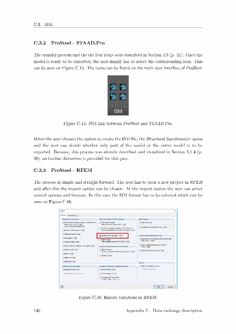
C.3.3 ProSteel - RFEM
The process is simple and straight forward. The user has to open a new project in RFEM
and after this the import option can be chosen. At the import option the user can select
several options and formats. In this case the ISM format has to be selected which can be
seen on Figure C.16.
Figure C.16: Import variations in RFEM.
140 Appendix C. Data exchange description

C.4. IFC
When the �le was selected and accepted the program o�ers another option for the user,
which is, either to import the physical or the analytical model. In this case the analytical
model is selected. This can be seen on the �gure below.
Figure C.17: Possibility of choice to import physical or analytical model in RFEM.
When the user decides about the physical or analytical model, the import process �nishes
and the model can be used for further analysis.
C.4 IFC
C.4.1 Revit
For Revit there was a separate extension, which expanded its export capabilities signi�-
cantly. It allowed for a very high level of customization and had many prede�ned MDVs
that were easy to use to modify certain elements of them to �t a speci�c scenario. This
extension was downloaded from the Autodesk App Store for free. Figure C.18 shows the
user-interface for the IFC export.
Appendix C. Data exchange description 141

C.4. IFC
Figure C.18: IFC export interface in Revit.
To create the IFC �le properly, meaning that the required information is exported to it
in an accurately de�ned data structure, the Revit objects needed to be mapped to the
appropriate IFC entities. This was done in the IFC export settings which is shown in
Figure C.19. Revit has a default setting for this, but it should be examined and if needed
adjusted to the speci�c project.
Figure C.19: IFC mapping interface in Revit.
Aside from the various included MVDs, it was also possible to create a user-de�ned MVD
based on one of the prede�ned ones, which also allowed for the inclusion of custom property
sets. This could be done with a speci�c txt �le that had to be created manually by the
user. This txt �le speci�ed the information that the user wanted to export and mapped
the Revit property to a suitable IFC entity.
142 Appendix C. Data exchange description

C.4. IFC
C.4.2 Tekla Structures Learning
In Tekla Structures Learning, the method to create the IFC �le was quite similar to Revit,
however it did not have the same amount of prede�ned MVDs. The export could be done
in the IFC export interface window, shown in Figure C.20.
Figure C.20: IFC export interface in Tekla Structures Learning.
As with Revit, it was also possible to create custom property sets with Tekla Structures
Learning, allowing for the inclusion of user de�ned attributes for each object. Every sup-
ported property can be chosen from a separate window, where the attributes can be indi-
vidually modi�ed and assigned to an IFC entity. It can be seen in Figure C.21.
Figure C.21: IFC mapping interface in Tekla Structures Learning.
Appendix C. Data exchange description 143

C.4. IFC
C.4.3 Bentley AECOsim Building Designer
As in Revit and Tekla Structures Learning, AECOsim also has the option to export and
import IFC. The software only supports IFC2x3 format, as it can be seen on �gure C.22.
Figure C.22: IFC exporting in AECOsim.
As with the previous software, mapping of the di�erent objects was also done in AECOsim.
The di�erence in AECOsim was, that the object mapping was done automatically by the
program itself. Although, there was an opportunity to do it manually, this option was really
complicated, therefore a good overall insight of the software is recommended. Also, at this
time manual mapping was limited, only �ve attributes (reference, slope, span, load-bearing
and �re rating) could be modi�ed. This is shown on �gure C.23.
144 Appendix C. Data exchange description

C.5. Tekla Structures Learning - RFEM direct link
Figure C.23: Manual mapping in AECOsim Building Designer.
It is important to note here, that at STAAD.Pro the import of the IFC was di�erent than
for the other software investigated in this project. STAAD.Pro was the only exception
where the IFC �le had to be converted into an ISM �le. After this, the ISM �le could be
imported into STAAD.Pro for further analysis.
C.5 Tekla Structures Learning - RFEM direct link
There are several data exchange options between Tekla Structures Learning and RFEM.
In the following the import method is described, but it is also possible to export the model
from RFEM to Tekla Structures Learning and thus updating the model. In this project
the direct import from Tekla Structures Learning is used to import the analytical model
of the structure. During the transfer the user can either click on the 'Direct import from
Tekla Structures' or go into 'File' and 'Import', where the window shown in Figure C.24
will appear.
Appendix C. Data exchange description 145

C.5. Tekla Structures Learning - RFEM direct link
Figure C.24: Import options in RFEM.
As it can be seen RFEM supports several data exchange formats. Under 'Direct Imports'
Tekla Structures is chosen and the user is presented with the following window with import
options c.f. Figure C.25. In this windows the user can choose either 'Physical Model' or
'Analytical Model'. It is also possible to tick of several options e.g. 'Import load cases'
and 'Set Z-axis upward' (if this is not ticked the z-axis will be set downwards).
Figure C.25: Import options in RFEM.
The user can also de�ne conversation �les for cross-section and material. This is done
under 'Detail settings' shown in Figure C.26 during the import process.
146 Appendix C. Data exchange description

C.6. CIS
Figure C.26: Detailed import settings.
C.6 CIS
In Tekla Structures Learning the user can choose to export two types of model: the 'Anal-
ysis Model' or the 'Design/manufacturing Model' c.f. Figure C.27
Figure C.27: Export from Tekla Structures Learning using CIS.
In this case 'Analysis Model' is chosen. The user is then presented with the following
window, shown in Figure C.28
Appendix C. Data exchange description 147

C.7. Tekla Structures Learning - Abaqus/CAE
Figure C.28: Export CIS Analysis model.
The user needs to choose CIS version, in this case CIS/2 was chosen, since this is what
STAAD.Pro is compatible with. In step �le box, the user needs to write the stp �le title,
which is the �le imported into STAAD.Pro. From the �avour list, European standard was
chosen. Furthermore, 'Yes' option was chosen in 'Split members' box. For example a beam
may be connected to three columns, so that one of the columns supports the beam in the
middle and the other two in each end of the beam. By enabling 'Split members' the beam
is split into two equal elements in the CIS model. If 'No' is selected there will be just one
beam element with two nodes; one in each end.
C.7 Tekla Structures Learning - Abaqus/CAE
The transfer procedure is initiated by 'File' and 'Export' in Tekla Structures Learning.
Then, the user needs to select 'DWG/DXF...' as shown in Figure C.29, and is presented
with the window in Figure C.30.
148 Appendix C. Data exchange description

C.7. Tekla Structures Learning - Abaqus/CAE
Figure C.29: Export to dwg �le.
In the export settings menu, as shown in Figure C.30, 'Export as Faces' were chosen with
high part accuracy.
Figure C.30: Export to dwg �le settings.
Other options available are 'Lines' (exports parts as lines located in the center of the
pro�le cross-section), 'Center lines' (exports parts as part center lines) and 'Reference
lines' (exports parts as reference lines, drawn between the creation points). In this case,
'Export as Faces' were best suited.
The frame corner created in Tekla Structures Learning is imported as a polyface mesh into
Abaqus/CAE. The user needs to geometrically mesh the imported part, as shown in Figure
C.31. After meshing the frame corner, the user needs to convert the geometrical mesh to
a 3D solid by 'Convert to Solid' feature.
Appendix C. Data exchange description 149

C.7. Tekla Structures Learning - Abaqus/CAE
Figure C.31: Mesh in AutoCAD.
To geometrically mesh the part, mesh options shown in Figure C.32 were used. The settings
were not changed from the default values aside from mesh type and mesh distance from
original face.
Figure C.32: Mesh options in AutoCAD.
The meshing part is only necessary in order to change the polymesh face to 3D solid in
AutoCAD. Finally, the di�erent parts of the frame corner were combined to just one part
by use of 'Solid, union' under 'Solid' tab.
Figure C.33: Combine several 3D solid parts to one 3D solid part.
Once the frame corner is exported to Abaqus/CAE, it is easier to deal with just one part
instead of several parts. In the latter case the user needs to assemble the di�erent parts to
150 Appendix C. Data exchange description

C.7. Tekla Structures Learning - Abaqus/CAE
one part in Abaqus/CAE, de�ne constraint between the di�erent parts and assign material
and cross-section for each part separately.
Appendix C. Data exchange description 151

C.7. Tekla Structures Learning - Abaqus/CAE
152 Appendix C. Data exchange description

Appendix DSolid to shell conversion in Abaqus/CAE
In the process of converting solid to shell, �rstly 'Assign Midsurface Region' feature is used,
where the whole model is selected as a region. Then, 'O�set Faces' feature was used to
o�-set the faces of the top �ange to just one shell part at the center of the solid part. And
same procedure with the bottom �ange and the web. After o�-setting faces of upper- and
bottom �anges and the web, it was necessary to use 'Extend Faces' feature, since there
was gaps between the �anges and the web. The web was extended to the �ange in each
side. Moreover, it was necessary to use use 'Remove Faces', since the edge of the web in
the upper part of the frame was not aligned with the edge of the web in lower part, c.f.
Figure D.1.
XYZ
Figure D.1: Use of 'Remove Faces' feature in Abaqus/CAE.
153

154 Appendix D. Solid to shell conversion in Abaqus/CAE

Appendix EList of external appendixes
The external appendix consists of a DVD with the following content.
1. Simple Cases
� Beam FEM-Design
� Beam Revit
� Beam RSA
� Beam Tekla Structures Learning
� Frame FEM-Design
� Frame Revit
� Frame RSA
� Frame Tekla Structures Learning
2. Advanced Cases
� Conveyor bridge from 3D Structural Design
� Platform structure from ISC
� Fatigue analysis
� Buckling analysis
155