aalborg universitet q-enhancement in rf cmos filters case
TRANSCRIPT

Aalborg Universitet
Q-enhancement in RF CMOS Filters
Case Study: Direct Conversion Transmitters for UMTS
Madsen, Per
Publication date:2005
Document VersionPublisher's PDF, also known as Version of record
Link to publication from Aalborg University
Citation for published version (APA):Madsen, P. (2005). Q-enhancement in RF CMOS Filters: Case Study: Direct Conversion Transmitters for UMTS.Aalborg Universitetsforlag.
General rightsCopyright and moral rights for the publications made accessible in the public portal are retained by the authors and/or other copyright ownersand it is a condition of accessing publications that users recognise and abide by the legal requirements associated with these rights.
- Users may download and print one copy of any publication from the public portal for the purpose of private study or research. - You may not further distribute the material or use it for any profit-making activity or commercial gain - You may freely distribute the URL identifying the publication in the public portal -
Take down policyIf you believe that this document breaches copyright please contact us at [email protected] providing details, and we will remove access tothe work immediately and investigate your claim.
Downloaded from vbn.aau.dk on: January 25, 2022

PhD Thesis
Q-enhancement in RF CMOS FiltersCase Study: Direct Conversion Transmitters for UMTS
March 3, 2005
Per Madsen,Industrial PhD student (EF 871),E-mail: [email protected].
Texas Instruments Denmark A/S,Sofiendalsvej 93,9200 Aalborg SV,Denmark.
RF Integrated Systems & Circuits (RISC) group,Center for TeleInFrastructure (CTIF),Aalborg University (AaU),Fredrik Bajers Vej 7-A6,DK-9220 Aalborg,Denmark.


Q-enhancement in RF CMOS FiltersCase Study: Direct Conversion Transmitters for UMTS
Per Madsen,Industrial PhD student (EF 871),
E-mail: [email protected].
ISBN – 87 – 90834 – 70 – 4ISSN – 0908 – 1224R04 – 1026
The presented thesis, consisting of seven papers and an extended summery, has been submittedfor evaluation for an industrial PhD.
Industrial PhD ProgramThe presented thesis documents the research project completed as a part of the Danish indus-trial PhD education. This education is administrated by the Committee on Industrial PhD Fel-lowship under the Danish Academy of Technical Sciences (ATV), and is financially supportedby the Danish Agency for Trade and Industry under the Ministry of Business and Industry.
Abstract
The research project investigates the use of a Q-enhanced LC resonators in monolithicUMTS transmitters, implemented in a standard CMOS process.
The project was started in the summer of 2000. At this time there was only limitedavailable information about how to design transmitters for UMTS. UMTS transmitter per-formance is, among other things, specified by Adjacent Channel Leakage Ratio (ACLR) andError Vector Magnitude (EVM). Relations between ACLR, EVM and various circuit imper-fections are investigated through simulations and measurements using real UMTS signalsand test equipment. The direct up-conversion transmitter is found to be the best architec-ture for integration on CMOS. However, it requires a bandpass filter with a pass band inthe GHz range in order to meet requirements to noise in the downlink band.
It is investigated how such an RF bandpass filter may be implemented on CMOS. Pas-sive on-chip resonators can only be implemented with low Quality factor (Q) because oflosses in on-chip inductors. It is possible to compensate for these losses with active circuits.Such a circuit is implemented using a topology, where transistors and capacitors are used togenerate a negative differential conductance. An expression for the differential admittanceof this circuit is derived and verified through measurements.
The Q-enhancement circuit is used in an LC resonator designed for operation at 1950 MHz.The concept of Q-enhancement works fine, but the use of reactive components in the Q-enhancement circuit limits the freedom in the design of the resonator. The measured cen-ter frequency was 1850 MHz and the tuning range approximately 90 MHz. This could berecreated in simulations if measured data for Metal Insulator Metal (MIM) capacitors andvaractors were used instead of the design kit provided by the foundry.


PhD Thesis R04-1026 , March 3, 2005.Texas Instruments Denmark A/S & RISC group, AaU
Preface
The research project document in this thesis was made at the RF Integrated Systems & Circuit(RISC) group at Center for TeleInFrastruktur (CTIF) at Aalborg University. The research withinRISC covers system analysis, chip design and analysis of single devices.
The project was initiated in collaboration between Telital R&D Denmark, RISC and the DanishAcademy of Technical Sciences (ATV). The project was planned to follow a line, starting witha thorough analysis how to design transmitters for UMTS. This system was chosen becauseTelital R&D Denmark was starting up the design of their first transmitter for UMTS when theproject was planned. No system knowledge was available at the time and the project washoped to remedy this. The official start of the project is 1st of August 2000. However, TelitalR&D Denmark did not receive their transmitter tester for UMTS before the spring of 2001. Thismeant that the system analysis could not be backed up with measurements before this time.The measurements did in fact prove an initial expression for IQ phase offset to be wrong andtherefore caused a new version to be derived. The system analysis investigated a transmitterarchitecture for implementation on CMOS. A critical block in this architecture was selected todemonstrate if and how it could be implemented on CMOS. The system analysis was finishedin the early winter of 2002. The conclusion was that a direct up-conversion transmitter was thebest immediate choice. It required an RF bandpass filter to meet requirements to noise in thedownlink band. This filter was selected for implementation in CMOS. It was known that theRISC group needed to change CMOS process from the beginning of the project. A test chip wassubmitted in the new process in the late spring of 2001. However, when the PhD student wasready to start the design in the spring of 2002, it had not yet arrived and it was decided to usea different foundry. The choice of Q-enhancement circuit was therefore based on simulationsconducted with the design kit provided by the new foundry, even though it was not knownhow well this design kit matched reality. Newer the less a 2nd order filter was designed and alayout containing this together with sub-circuits and test structures was submitted in the earlysummer of 2002. In the meantime Telital R&D Denmark got into financial difficulties. It wasarranged that the PhD student could be transferred to Texas Instruments Denmark A/S in thesummer of 2002. The first chip from the new foundry was received in the fall of 2002, but amanufacturing error meant that the transistors only had half the gain available in the designkit. Functional chips were received in December 2002. Investigations conducted during thespring and summer of 2003 revealed two major errors on the designed circuits that renderedthe designed filter useless. After two more chip runs, the latest received in the fall of 2003, theQ-enhancement circuit was functional and the analysis presented in this thesis could be carriedout.
The presented thesis contains seven publications and an extended summery. Chapter 1 gives ashort introduction to each paper, while chapter 2 to 8 make up the extended summery. Chapter2 gives an introduction to the project, its background, aim and areas where the author believeshis research has made significant contributions. Chapter 3 sums up and updates the systemanalysis. It is based on work published in [6, 4, 7, 5]. Chapter 4 investigates how the desired fil-ter may be implemented with special emphasis on required Q and tuneability of the resonators.Chapter 5 investigates how resonators may be implemented. This section relies heavily on lit-erature studies. Chapter 6 describes the Q-enhancement circuit designed in this project. It is
PAGE 3

PER MADSEN
based on [1, 2]. Chapter 7 describes an experiment where the Q-enhancement circuit is usedin an LC tank, based on [3]. It also concludes on the usability of the proposed Q-enhancementcircuit.
The road through this project has been long and bumpy. With the help and understandingfrom many persons it has, never the less, been possible to reach a point where the presentedthesis can be submitted. First of all the student would like to thank Torben Amtoft, Telital R&DDenmark, Torben Larsen and Troels Emil Kolding, both from RISC, for starting this project,ATV for supporting it financially and Willy Bergstrøm for representing the project at ATV. Thestudent would further more like to thank Torben Amtoft, Torben Larsen, Troels Emil Kolding,Jan Hvolgaard Mikkelsen and Jens Christian Lindof for being supervisors during the project.The student would like to thank Arne Bisgaard Kristensen and Jens Arne Hald at Telital R&DDenmark for arranging for the project to be continued at Texas Instruments Denmark A/S,when Telital R&D Denmark could no longer continue the project. The student would furthermore like to thank Finn Andersen and Jens Christian Lindof at Texas Instruments DenmarkA/S for continuing the project there. Finally the student would like to thank former collegesat Telital R&D Denmark together with new colleges at Texas Instruments Denmark A/S andRISC for their support during the project.
REFERENCES
[1] P. Madsen, T. Larsen, J. H. Mikkelsen, and J. C. Lindof. On the design of a differential common collector negativeresistance. In Proceedings of the 21st Norchip Conference, pages 100 – 103, Riga, Latvia, November 2003. Norchip,IEEE.
[2] P. Madsen, T. Larsen, J. H. Mikkelsen, and J. C. Lindof. An RF CMOS differential negative resistance for Q-enhancement. In Proceedings of the 7th International Conference on Solid State and Integrated Circuit Technology,pages 1256 – 1259, Beijing, October 2004. ICSICT.
[3] P. Madsen, T. Larsen, J. H. Mikkelsen, and J. C. Lindof. An RF CMOS Q-enhanced LC resonator. Oslo, November2004. Accepted for: Norchip 2004.
[4] Per Madsen. Simulating overall performance requirements for transmitters in IMT 2000 FDD user equipment. InProceedings of the European Conference on Wireless Technology, Wireless Technologies 2001, pages 47 – 50, London,September 2001. European Microwave Week.
[5] Per Madsen. Simulation of EVM due to circuit imperfections in UMTS/FDD transmitters. In Proceedings of theNordic Matlab Conference 2003, pages 179 – 184, Copenhagen, October 2003. COMSOL.
[6] Per Madsen, Ole Kiel Jensen, Torben Amtoft, Ragner V. Reynisson, Jan H. Mikkelsen, Søren Laursen, Cristian R.Iversen, Troels E. Kolding, Torben Larsen, and Michael B. Jenner. RF requirements for UTRA/FDD transceivers.In Proceedings of WPMC’ 01, volume 1, pages 197 – 202, Aalborg, Denmark, September 2001. Wireless PersonalMultimedia Communications.
[7] Per Madsen, Ole Kiel Jensen, Torben Amtoft, Ragner V. Reynisson, Jan H. Mikkelsen, Søren Laursen, Troels E.Kolding, Torben Larsen, and Michael B. Jenner. UTRA/FDD RF transceiver requirements. Wireless PersonalCommunications, 1(23):55–66, 2002.
PAGE 4

PhD Thesis R04-1026 , March 3, 2005.Texas Instruments Denmark A/S & RISC group, AaU
Contents
1 Publications 71-1 RF Requirements for UTRA/FDD Trancievers . . . . . . . . . . . . . . . . . . . . 71-2 Simulating Overall Performance Requirements for Transmitters in IMT 2000 FDD
User Equipment . . . . . . . . . . . . . . . . . . . . . . . . . . . . . . . . . . . . . . 71-3 UTRA/FDD RF Transceiver Requirements . . . . . . . . . . . . . . . . . . . . . . 81-4 On the Design of a Differential Common Collector Negative Resistance . . . . . . 81-5 Simulation of EVM Due to Circuit Imperfections in UMTS/FDD Transmitters . . 91-6 An RF CMOS Differential Negative Resistance for Q-enhancement . . . . . . . . 91-7 An RF CMOS Q-enhanced LC Resonator . . . . . . . . . . . . . . . . . . . . . . . . 9
2 Introduction 112-1 Background . . . . . . . . . . . . . . . . . . . . . . . . . . . . . . . . . . . . . . . . 112-2 Research Topics . . . . . . . . . . . . . . . . . . . . . . . . . . . . . . . . . . . . . . 112-3 Scientific Contribution . . . . . . . . . . . . . . . . . . . . . . . . . . . . . . . . . . 12
3 Case Study: UMTS Transmitters 133-1 Overall Transmitter Requirements . . . . . . . . . . . . . . . . . . . . . . . . . . . 133-2 Transmitter Architectures . . . . . . . . . . . . . . . . . . . . . . . . . . . . . . . . 163-3 Conclusion . . . . . . . . . . . . . . . . . . . . . . . . . . . . . . . . . . . . . . . . . 22
4 Filter Transfer Function 254-1 Approach I . . . . . . . . . . . . . . . . . . . . . . . . . . . . . . . . . . . . . . . . . 264-2 Approach II . . . . . . . . . . . . . . . . . . . . . . . . . . . . . . . . . . . . . . . . 294-3 Conclusion . . . . . . . . . . . . . . . . . . . . . . . . . . . . . . . . . . . . . . . . . 30
5 Resonators 335-1 Implementation of resonators . . . . . . . . . . . . . . . . . . . . . . . . . . . . . . 335-2 Noise and Dynamic Range . . . . . . . . . . . . . . . . . . . . . . . . . . . . . . . . 375-3 Conclusion . . . . . . . . . . . . . . . . . . . . . . . . . . . . . . . . . . . . . . . . . 38
6 Q-enhancement circuit 416-1 Low Frequency Experiment with Discrete BJTs . . . . . . . . . . . . . . . . . . . . 436-2 Monolithic RF CMOS implementation . . . . . . . . . . . . . . . . . . . . . . . . . 476-3 Conclusion . . . . . . . . . . . . . . . . . . . . . . . . . . . . . . . . . . . . . . . . . 52
7 Q-enhanced Resonator 557-1 Results . . . . . . . . . . . . . . . . . . . . . . . . . . . . . . . . . . . . . . . . . . . 567-2 Discussion . . . . . . . . . . . . . . . . . . . . . . . . . . . . . . . . . . . . . . . . . 577-3 Conclusion . . . . . . . . . . . . . . . . . . . . . . . . . . . . . . . . . . . . . . . . . 58
8 Conclusion 598-1 Important Results . . . . . . . . . . . . . . . . . . . . . . . . . . . . . . . . . . . . . 598-2 Scientific Contributions . . . . . . . . . . . . . . . . . . . . . . . . . . . . . . . . . . 598-3 Future Work and Research . . . . . . . . . . . . . . . . . . . . . . . . . . . . . . . . 60
PAGE 5


PhD Thesis R04-1026 , March 3, 2005.Texas Instruments Denmark A/S & RISC group, AaU
1 PUBLICATIONS
This chapter gives a short introduction to the publications made during the PhD project. Thepapers address the two major topics of this project, which are system analysis of UMTS trans-mitters and the design of a Q-enhancement circuit. The chapter contains seven sections namedafter the title of the paper they describe. The sections are arranged in the order in which thepapers were submitted. The description only includes the authors scientific contributions tothe papers.
1-1 RF Requirements for UTRA/FDD Trancievers
Authors: Per Madsen, Ole Kiel Jensen, Torben Amtoft, Ragner V. Reynisson,Jan H. Mikkelsen, Søren Laursen, Cristian R. Iversen, Troels E. KoldingTorben Larsen and Michael B. Jenner
Place: Wireless Personal Multimedia Communications (WPMC), Aalborg, DenmarkTime: September 2001
The analysis of the transmitter is based on the authors work. Overall requirements to thetransmitter are determined from several factors. The specifications set requirements to EVM,ACLR and out of band noise, but the receiver sensitivity and the isolation in the duplex filtersets a requirement to how much noise the transmitter may emit in the downlink band. Overallrequirements to IQ balance, inband ripple, local oscillator feed through and phase noise areset-up from the requirements to EVM. The ACLR requirement is converted to a specificationof a 1 dB compression point, as an simple relation between these parameters appeared to bepresent at the time of writing. A budget is set up for a direct conversion transmitter based onthese requirements. It is found that an RF bandpass filter is required in order to suppress noisein the downlink band.
1-2 Simulating Overall Performance Requirements for Transmitters in IMT 2000 FDD User Equip-ment
Author: Per MadsenPlace: European Conference on Wireless Technology, London, EnglandTime: September 2001
This paper investigates how a number of different circuit imperfections affect EVM and ACLR intransmitters for UMTS FDD. It sets up analytical expressions for these parameters in order toprovide a simple means to make budgets. All the expressions are verified through measure-ments. The included parameters are: Quantization, IQ phase and amplitude imbalance, phasenoise and linearity. It was found that phase and amplitude adjustments could improve EVM asfunction of IQ imbalance. Further more no simple relation between 3rd order output interceptpoint or 1 dB compression points and ACLR were found.
PAGE 7

PER MADSEN
The expressions for IQ imbalance has caused much interest in the public. So much in fact thatthe student later made a short document where the expressions were derived. This documentwas then handed to persons who made enquiries.
1-3 UTRA/FDD RF Transceiver Requirements
Authors: Per Madsen, Ole Kiel Jensen, Torben Amtoft, Ragner V. Reynisson,Jan H. Mikkelsen, Søren Laursen, Troels E. Kolding, Torben Larsenand Michael B. Jenner
Place: Wireless Personal Communications, Kluwer Academic PublishersTime: October 2002
The paper submitted to WPMC was selected for a reprint at Kluwer Academic Publishers:Journal of Wireless Personal Communications, special issue: Wireless Personal MultimediaCommunications. Although the paper was a reprint it is shorter than the original paper. Thismeant that some adjustments had to be made to the contents. The major changes were made inthe section describing the overall receiver requirements, which relies more on references in thispaper. In the transmitter section an expression is presented, that describes how ACLR addsand the budget of 1 dB compression points is replaced with an ACLR budget. This was doneafter it was found that no simple relation between ACLR and 1 dB compression point could beestablished.
1-4 On the Design of a Differential Common Collector Negative Resistance
Authors: Per Madsen, Torben Larsen, Jan H. Mikkelsen and Jens C. LindofPlace: 21st Norchip Conference, Riga, LatviaTime: November 2003
This paper describes an experiment with a discrete implementation of a Q-enhancement circuitthat the student believes to be very interesting for his application. Simulations indicated thatthe most often used Q-enhancement circuit would have difficulties in providing sufficient lin-earity for the desired application. Therefore a differential version of a circuit was implemented,whos single ended counter part in theory could be designed to perform better. However, thetheory is based on simple representations of transistor parasitics. The paper presents an ex-pression that includes more transistor parasitics to describe the differential admittance of thiscircuit. The paper focus on the verification of the expression. The circuit is therefore designedto operate at low frequencies and implemented using discrete components. This makes it possi-ble to measure the components that are were used in the circuit with a high degree of accuracy.The new expression was found to be much more accurate than the more simple expression,whos equivalents are seen in the literature for single ended versions of the circuit. However,the match is not perfect.
PAGE 8

PhD Thesis R04-1026 , March 3, 2005.Texas Instruments Denmark A/S & RISC group, AaU
1-5 Simulation of EVM Due to Circuit Imperfections in UMTS/FDD Transmitters
Authors: Per MadsenPlace: Nordic Matlab Conference 2003, Copenhagen, DenmarkTime: October 2003
This paper address the same general issues that were addressed in: " Simulating Overall Perfor-mance Requirements for Transmitters in IMT 2000 FDD User Equipment", but being submittedto a MATLABTM conference, methodology and simulated results are also included. The paperincludes effects of IQ phase and amplitude imbalance, phase noise, filtering and time offsets be-tween phase and magnitude in polar modulators. It further more presents simulations of howseveral interferences combines. A new expression has been derived for IQ phase imbalance.The previous expression was based on an educated guess of the optimal phase compensation.The expression presented here uses an analytically calculated optimum. There were no signifi-cant difference between the results obtained with the two expressions.
1-6 An RF CMOS Differential Negative Resistance for Q-enhancement
Authors: Per Madsen, Torben Larsen, Jan H. Mikkelsen and JensPlace: The 7th International Conference on Solid State and Integrated Circuit
Technology, Beijing, ChinaTime: October 2004
This paper presents an implementation of the differential Q-enhancement circuit, presented in:"On the Design of a Differential Common Collector Negative Resistance", on RF CMOS. Thepaper shows simulated and measured 2-port S-parameters and describes the steps necessaryto obtain the reported fit. The paper further more reports the obtained differential admittancedivided in conductance and equivalent capacitance. Here measured results are compared withsimulations and estimates made using the more detailed expression presented in: "On the De-sign of a Differential Common Collector Negative Resistance". The circuit is capable of provid-ing a differential conductance at -2.8 mS and an equivalent capacitance of approx 1 pF at 2 GHzwith a current consumption of 32 mA. However, the most interesting result of the paper is thatthe described method enables the expression to estimate the admittance with less than 20 %error.
1-7 An RF CMOS Q-enhanced LC Resonator
Authors: Per Madsen, Torben Larsen, Jan H. Mikkelsen and Jens C. LindofPlace: 22nd Norchip Conference, Oslo, NorwayTime: November 2004
This paper presents and example of how the Q-enhancement circuit presented in: "An RFCMOS Differential Negative Resistance for Q-enhancement" may be used in a on chip LC res-
PAGE 9

PER MADSEN
onator. The resonator consists of an inductor, through which the active transistors are biasedand a bank of varactors that provide tune-ability of the resonator frequency. The inductor isimplemented with four windings and symmetry around the bias feed point. The differential in-ductance is in the order of 5.6 nH, while the conductance is 2 mS. It was found that a 3-port rep-resentation of the inductors was required to make simulated S-parameters fit measurements.The varactors were implemented with nFETs. The design kit was found not to simulate weakaccumulation mode well, so measurements on stand alone circuits were used instead. Thisprovided an accuracy of 3 MHz between simulated and measured resonance frequency. TheQ-enhancement circuit was found to compensate the LC-resonator, while consuming a total of6.9 mA. The Q-enhancement circuit is thus more than capable of compensating for losses in theresonator.
PAGE 10

PhD Thesis R04-1026 , March 3, 2005.Texas Instruments Denmark A/S & RISC group, AaU
2 INTRODUCTION
The presented PhD thesis documents a project that was started in August 2000. At this timenew standards for mobile telecommunications such as Universal Mobile TelecommunicationStandard (UMTS), General Packet Radio Service (GPRS) and Enhanced Data rates for GSMEvolution (EDGE) were emerging. These standards enables high data transfer rates, which intern enables new types of applications like video streaming, Moving Pictures Expert Grouplayer 3 (MPEG–3) sound, exchange pictures, etc. to run on mobile User Equipment (UE).
2-1 Background
The project conciders two major topics. System analysis and RF CMOS design. This sectiongives a short introduction to why these two topics were considered in the project.
The project was started as Telital R&D Denmark started the design of its first UMTStransmitter. The project was initiated in order to provide knowledge about how to design atransmitter for UMTS. Telital R&D Denmark had no experience with parameters like ErrorVector Magnitude (EVM) and Adjacent Channel Leakage Ratio (ACLR), which are used tospecify transmitter performance in UMTS [1]. It was therefore necessary to know how differentcircuit imperfections in the transmitter affect these parameters.
The ideal transceiver for design and manufacture of low cost mobile equipment would haveto be implemented as one component. Such a transceiver would reduce time spent on RadioFrequency (RF) design and increase production yield. An increase in complexity is neededto support the new capabilities provided by the high-speed digital standards. One way tohandle this increased complexity without an equivalent increase of complexity of the PrintedCircuit Board (PCB) is to implement several types of circuits on the same chip. This is denotedSystem On Chip (SoC). SoC is excellent to combine digital circuits, but analog circuits can alsobe added. To obtain the full advantage of SoC, no external circuits, except for the relevanttransducers like speaker, microphone, video camera, etc. and battery, should be required. Thisimplies that the radio circuits are fully integrated on the chip with only one connection to theantenna. The project uses the design of a UMTS transmitter as a case study for RF circuitdesigns intended for SoC.
2-2 Research Topics
The research activities the project goes in two directions. (i) A thorough system analysis ismade on the UMTS transmitter. It establishes how design parameters, such as phase noise,In-phase and Quadrature (IQ) imbalance, linearity, - etc. affect EVM and ACLR. This is usedin an analysis of transmitter architectures in order to find out how a UMTS transimitter forFrequency Division Duplex (FDD) can be implemented. This part of the project is concludedwith a specification of the blocks in an architecture that is believed to be suitable for SoC. (ii)The transmitter is expected to be implemented on Complementary Metallic Oxide Semicon-ductor (CMOS) as this is a relative cheap process that is well suited for digital circuits andhence SoCs. However component tolerances and poor quality in on-chip inductors make vital
PAGE 11

PER MADSEN
RF circuits inefficient. In this project one circuit that is critical for the selected transmitter mustbe implemented on a standard CMOS process.
2-3 Scientific Contribution
The research contributions of this project are represented through the papers described in chap-ter 1. This section draws the up the areas in which the project, to the knowledge of the author,has provided scientific contributions.
EVM and ACLR were unknown to Telital R&D Denmark when the project was started. Asearch in the literature revealed only little material on this topic. Major scientific contributionsfrom this work are the expressions that relate IQ amplitude and phase imbalance to EVM. Theproject tests expressions derived by both the author and others against measurements con-ducted with true W-CDMA signals and test-equipment. The latter is important in order toensure that assumptions made on the signals are valid.
Telital R&D Denmark did not know how to make transmitters for UMTS, when the projectwas started. Vendors suggested heterodyne up-conversion, but this project has shown thatdirect up-conversion or polar modulation are probably better choices. It was found that thetransmitter noise in the down link band is the major problem with direct (and heterodyne) up-conversion transmitters. An RF bandpass filter must be inserted before the Power Amplifier(PA) to meet requirements to this noise.
The RF bandpass filter was chosen for implementation in CMOS. Q-enhanced LC resonatorswere found to be best suitable for this application. The application in the transmitter setsparticularly harsh requirements to linearity and this has caused the author to implement aQ-enhancement circuit that is not normally used in differential applications. A detailed ex-pression for the differential admittance of this circuit has been set up and verified throughmeasurements on implemented circuits.
REFERENCES
[1] 3rd Generation Partnership Project (3GPP). UE radio transmission and reception (FDD), technical specification25.101 v.6.4.0, March 2004.
PAGE 12

PhD Thesis R04-1026 , March 3, 2005.Texas Instruments Denmark A/S & RISC group, AaU
3 CASE STUDY: UMTS TRANSMITTERS
This chapter addresses system aspects of transmitters for UMTS. It is based on [16, 14, 17, 15]and demonstrates how a transmitter for UMTS can be designed. The analysis starts with aninvestigation of overall requirements the transmitter. These requirements are converted tospecifications of the performance of individual blocks in a selected transmitter architecture.This investigation includes an analysis of how circuit imperfections affect measured parame-ters, such as EVM and ACLR [1]. The investigation is based on FDD steady state operationfor UMTS-FDD transmitters for power class III band I [1], but some results may apply to othermodes as well. The up-link band is defined from 1920 MHz to 1980 MHz and the down linkband from 2110 MHz to 2170 MHz.
3-1 Overall Transmitter Requirements
This section describes the requirements to UMTS transmitters. These requirements are dictatedby the specifications [1] together with the performance of the duplex filter and the receiver.
3-1-1 Duplex Filter
The UMTS-FDD system operates in full duplex. This means that the transmitter branch (Tx)and receiver branch (Rx) may be active at the same time. Therefore the two branches musthave access to the antenna at the same time. A duplex filter allows this as illustrated in Figure1. The duplex filter separates the two signals in the frequency domain with filters, but completeseparation can not be achieved. Some Tx power will leak to the Rx branch, due to limited atten-uation in filters and cross talk between the Rx and Tx traces. This is indicated with "Tx leakage"in Figure 1.
FIGURE 1: Functionality of the duplex filter. Up-link and Down-link is separated, but some Tx leakage to theRx branch can not be avoided.
The isolation between Rx and Tx is important for the performance of the receiver, becauseboth the high power up-link signal and transmitter noise in the Rx band interferes with thereceiver [16]. However the isolation in the duplex filter has to be weighted against insertionloss. Table 3.1 lists the amount of insertion loss and isolation to be expected in duplex filtersfor UMTS [19, 3].
PAGE 13

PER MADSEN
TABLE 3.1: Specification of duplex filter.Frequency band Attenuation [dB]Tx - Antenna1920 MHz < f < 1980 MHz < 2Antenna - Rx2110MHz < f < 2170MHz < 2Tx - Rx Isolation1920 MHz < f < 1980 MHz > 502110 MHz < f < 2170 MHz > 44
3-1-2 Requirements at the Transmitter Output
The requirements to the transmitter output signal are based on the specifications for UMTS-FDD [1] and the requirement to transmitter noise leakage to Rx in [16, 17]. [16] presents a re-ceiver noise budget, where the noise contribution in the Rx band is assumed to -111 dBm/3.84 MHz.It is assumed that a duplex filter can provide 44 dB isolation in the Rx band [19, 3]. The spec-ifications allow the transmitter to leak -60 dBm/3.84 MHz to the antenna in the Rx band [1],but the transmitter must generate no more than -67 dBm/3.84 MHz in order not to degradethe receiver significantly [16]. Assuming that the duplex filter defined in Table 3.1 is used, therequirements to the steady state output signal of the transmitter are as presented in Table 3.2.
The spectrum emission mask is defined to match ACLR and requirements made by systemsoperating on neighbour frequency bands [5, 6, 4]. It is introduced to ensure co-existence withother systems, operating at bands where the ACLR measurement makes no sense [5, 6, 4]. Ifnothing is indicated, it is assumed that the spectral emission mask requirements are meet if theACLR requirements are meet. This is in agreement with observations made during measure-ments on PAs.
Both EVM and peak code domain error describe the signal quality [1]. EVM describes the ratiobetween the averaged error power in the transmitted signal and the averaged power of theequivalent error-free signal as expressed by Eq. (5) in [15]. Peak code domain error expresseshow the error is distributed in the code domain [12]. The error signal is de-spread with allcodes in the domain [12]. Code Domain Error (CDE) is the ratio between the power of the errorsignal, de-spread with one code, and the power of the error free signal [12]. If the error signalsare mutually uncorrelated and evenly distributed over all the codes, there is a simple relationbetween CDE and EVM [7, 23]:
CDE = 10 · log10
(EVM2
SF
)(3.1)
where EVM is expressed in decimal scalars and SF is the spreading factor. Peak code domainerror is specified as the largest of the CDE values, measured on a signal where the spreadingcodes are 4 chips long [1]. EVM is specified to 17.5 % so according to Eq. (3.1), CDE should be-21.2 dB. However the uplink spreading code are not completely orthogonal so some margin
PAGE 14

PhD Thesis R04-1026 , March 3, 2005.Texas Instruments Denmark A/S & RISC group, AaU
TABLE 3.2: Specification of output signal.Parameter Values UnitFrequency of operationMin 1920 MHzMax 1980 MHzSignal powerMax average power > 26 dBm/3.84 MHzMin average power < -48 dBm/3.84 MHzSignal QualityAverage EVM < 17.5 %Peak Code Domain Error < -15 dBSpectrum emission maskfC± 2.5 MHz < -35 dBc/30 kHzfC± 3.5 MHz < -35 dBc/1 MHzfC± 7.5 MHz < -39 dBc/1 MHzfC± 8.5 MHz < -49 dBc/1 MHzfC± 12.5 MHz < -49 dBc/1 MHzOr no more than: < -55.8 dBm/1 MHzAdjacent channel leakagefC± 5 MHz > 33 dBfC± 10 MHz > 43 dBOr no more than: < -48 dBm/3.84 MHzInband spurious signalsf>12.5 MHz < -28 dBm/1 MHzOut of band spurious emissions1805 MHz < f < 1880 MHz <- 69 dBm/100 kHz1893.5 MHz < f < 1919.6 MHz < -39 dBm/300 kHz2110 MHz < f < 2170 MHz < -67 dBm/3.84 MHz
PAGE 15

PER MADSEN
must be added [7]. Hence -15 dB is used [7], but this is approximately the same noise to signalratio that is required to achieved an EVM of 17.5 %. This means that the requirement to peakcode domain error is meet if the transmitter meets the EVM requirement, even if all the powerin the error vector is projected on to one code. Peak code domain error is thus ignored in thisanalysis.
3-2 Transmitter Architectures
This section investigates which kind of transmitters may be used for UMTS and which re-quirements are made to the functional blocks in the particular transmitter. The signal modula-tion is a limiting factor, when it comes to choosing a suitable transmitter architecture. The W-CDMA up-link signal contains both amplitude and phase information. This means the modula-tion loop used for GSM can not be used, because it can not transfer the amplitude information.The most commonly suggested architectures for UMTS are direct up-conversion, heterodyneup-conversion, digital Intermediate Frequency (IF) and polar modulation [18, 24, 11, 22, 2, 20].
In the heterodyne transmitter up-conversion takes place in two stages. In-phase and Quadra-ture (IQ) components are modulated to some IF and then mixed to the desired frequency [18].The use of an IF means that the modulator can work on frequencies lower than where the trans-mission takes place. This may improve the accuracy of the IQ phase offset, but bandpass filtersare required both at IF and RF [18]. It is possible to design modulators for direct conversionwith sufficient precision of IQ to meet the EVM requirements [24, 13]. The main advantageof the heterodyne transmitter is thus not relevant for the UMTS transmitter, and the use of anextra filter makes it less attractive than other architectures.
In the digital IF architecture, the signal is converted to analog at IF. This means that the modu-lation of the IQ components is done digitally [11, 22]. The digital approach has the potential ofbeing more versatile and exact than the analog counter parts [11, 22], but the digital to analogconverters (DAC)s need to run at high frequencies to keep aliasing products from appearingin the uplink band or neighboring bands, where requirements to noise are particularly harsh.The same aliasing products cause the need for an IF bandpass filter. As was the case for theheterodyne transmitter, the advantages of the digital IF architecture are not relevant for theUMTS transmitter.
The remaining two architectures are exposed to more thorough investigations.
3-2-1 Direct Up-conversion
The Direct up-conversion transmitter is illustrated in Figure 2. The IQ components are con-verted directly to the desired frequency in the Quadrature Up-Converter (QUC). The gain isadjusted at RF in a Variable Gain Amplifier VGA [2] and in some cases the PA. Some filteringis required before the PA in order to ease requirements to the duplex filter [16]. Finally thePA amplifies the signal to the desired level.
Compared to the heterodyne transmitter this architecture saves circuits, but it also sets more
PAGE 16

PhD Thesis R04-1026 , March 3, 2005.Texas Instruments Denmark A/S & RISC group, AaU
FIGURE 2: Block diagram of a direct up-conversion transmitter.
harsh requirements to the used circuits [2]. The 90 phase shift in the modulator must be madeat RF, and the Local Oscillator (LO) should run a frequency outside the Tx band, to make it lesssensitive to interference from the transmitted signal.
The following describes which kind of requirements ACLR, EVM and out of band spuriousemissions sets to the blocks in the direct conversion transmitter. The presented work is basedon material published in [16, 14, 13, 15] and additional work performed by the author. Budgetshave been updated to fit reported state of the art performance.
All the circuits in the transmitter are non-linear and thus contribute to the overall ACLR. ThePA will typically be the largest contributor, because the signal power is highest here. There is nosimple relation between ACLR and the parameters most often used to describe non-linear per-formance [14]. Therefore ACLR is specified for each block [8, 21, 17]. Assuming that the contri-butions are mutually uncorrelated, the total ACLR generated by n cascaded circuits (ACLRT )can be found from the ACLR of circuits 1− n (ACLRm|m=1,2,...,n) using [17]:
ACLRT =1
n∑m=1
ACLR−1m
(3.2)
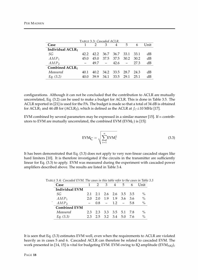
where ACLR is represented in scalars. However, due to the nature of non-linear distortion,the clause that the contributions must mutually uncorrelated may not apply. The expressionwas therefore verified experimentally for different ranges of ACLR. IQ signals were convertedto RF in a Signal Generator (SG) and then amplified with first one amplifier (AMP1) and thentwo amplifiers in cascade (AMP1 and AMP2). The power into the amplifiers was controlledwith attenuators and both ACLR at fC±5 MHz (ACLR1) and EVM were measured. ACLR1 andEVM was also measured on each amplifier and the SG alone, while exposed to the signals facedduring the tests. Eq. (3.2) is used to estimate the cascaded ACLR. In Table 3.3 the results arecompared with cascaded measurements. ACLR is averaged from measurements on fC +5 MHzand fC -5 MHz.
It is seen that Eq. (3.2) is a good estimate for levels of ACLR up to the required 33 dB, whilethe estimate becomes worse as ACLR increases further. The error is still less than 1 dB andmight originate from changing measurement setups for for individual amplifiers and cascaded
PAGE 17
PER MADSEN
TABLE 3.3: Cascaded ACLR.Case 1 2 3 4 5 6 UnitIndividual ACLR1SG 42.2 42.2 36.7 36.7 33.1 33.1 dBAMP 1 45.0 45.0 37.5 37.5 30.2 30.2 dBAMP 2 – 49.7 – 42.6 – 27.3 dB
Combined ACLR1Measured 40.1 40.2 34.2 33.5 28.7 24.3 dBEq. (3.2) 40.0 39.9 34.1 33.5 29.1 25.1 dB
configurations. Although it can not be concluded that the contribution to ACLR are mutuallyuncorrelated, Eq. (3.2) can be used to make a budget for ACLR. This is done in Table 3.5. TheACLR reported in [21] is used for the PA. The budget is made so that a total of 34 dB is obtainedfor ACLR1 and 44 dB for (ACLR2), which is defined as the ACLR at fC±10 MHz [17].
EVM combined by several parameters may be expressed in a similar manner [15]. If n contrib-utors to EVM are mutually uncorrelated, the combined EVM (EVMC) is [15]:
EVMC =
√√√√n∑
i=1
EVM2i (3.3)
It has been demonstrated that Eq. (3.3) does not apply to very non-linear cascaded stages likehard limiters [10]. It is therefore investigated if the circuits in the transmitter are sufficientlylinear for Eq. (3.3) to apply. EVM was measured during the experiment with cascaded poweramplifiers described above. The results are listed in Table 3.4.
TABLE 3.4: Cascaded EVM. The cases in this table refer to the cases in Table 3.3
.
Case 1 2 3 4 5 6 UnitIndividual EVMSG 2.1 2.1 2.6 2.6 3.5 3.5 %AMP 1 2.0 2.0 1.9 1.9 3.6 3.6 %AMP 2 – 0.8 – 1.2 – 5.8 %Combined EVMMeasured 2.3 2.3 3.3 3.5 5.1 7.8 %Eq. (3.3) 2.3 2.5 3.2 3.4 5.0 7.6 %
It is seen that Eq. (3.3) estimates EVM well, even when the requirements to ACLR are violatedheavily as in cases 5 and 6. Cascaded ACLR can therefore be related to cascaded EVM. Thework presented in [14, 15] is vital for budgeting EVM. EVM owing to IQ amplitude (EVMAIQ),
PAGE 18

PhD Thesis R04-1026 , March 3, 2005.Texas Instruments Denmark A/S & RISC group, AaU
phase imbalance (EVMPIQ) and RMS phase noise (EVMPN) can be expressed by [15]:
EVMAIQ ≈√√√√
∣∣∣∣∣ 2−√
2A2 + 1
(A + 1)
∣∣∣∣∣ · 100% (3.4)
EVMPIQ =
√1−
(cos
(ϕ
2
))2· 100% (3.5)
EVMPN ≈√
2− 2 cos(φ) · 100% (3.6)
where A is IQ amplitude offset ratio, ϕ is IQ phase offset from 90 and φ is the RMS phase erroron the LO. There is a correlation between ACLR and EVM in a non-linear device [14]. For anACLR of 33 dB, EVM is approximately 2.5 % [14]. [24] reports an A of 0.3 dB and a ϕ of 0.5 degand the GSM specifications prescribes RMS phase noise of maximum 5 deg. This performancecombines to an EVM of 9.25 % with phase noise being the largest contributor. The achievedEVM leaves a margin of 14.8 % for DACs and filtering, before the specified 17.5 % is reached.
Noise is the real killer in this architecture [16]. Requirements to the IF filter depends on thepower delivered by the DACs. This is because noise power levels and not signal to noise levelsare specified. Too much gain amplifies the noise floor to critical levels, even if the circuits werenoise less. Duplex filters have improved compared to the one used in [16] and PAs with of 26dB gain and a Noise Figure (NF) of 5 dB are reported [8, 21]. This means that the gain budgetand hence filter requirements should be re-evaluated. In Table 3.5 new budgets for inband gain,noise and ACLR are set up for the direct up-conversion transmitter in Figure 2. It assumes thatthe DACs deliver -15 dBm of signal power. The noise requirement to the filter is adjusted to
TABLE 3.5: Budgets for gain, noise and ACLR for the functional blocks in Figure 2.functional block QUC VGA FI PAGain [dB] 0 12 3 26NF [dB] 10 4 10 5ACLR ± 5 MHz [dB] 46 46 45 35ACLR ± 10 MHz [dB] 53 50 50 48.5
ensure that the transmitter meets requirements to noise from 1805 MHz to 1880 MHz. In thisbudget the filter is required to attenuate the Rx and Rx-image bands by 15 dB compared to theinband gain, while the NF at these bands is less than 15 dB. Increased NF in any of the blocksmust be compensated by either increased power from the DACs or attenuation in the filter. Toomit the filter completely, the DACs must deliver -1 dBm of power, but this is assumed not tobe realistic. The direct conversion transmitter therefore still requires a bandpass filter to meetrequirements to noise in UMTS downlink, as concluded in [16, 17], but the requirements to thefilter have been relaxed because of improved separation in the duplex filters.
PAGE 19

PER MADSEN
3-2-2 Polar Modulation
In the polar modulator the amplitude information is applied at RF. The PA is the best placeto apply the amplitude information, because it can be done power efficiently with a switchedPA and the remaining RF parts only handle constant envelope signals [20]. This is illustrated inFigure 3, where a Voltage Controlled Oscillator (VCO) is used to apply the phase informationto an RF signal. The figure employs an up-conversion loop well known from GSM today, butany control system that is capable of applying the phase information to the VCO should work.This is illustrated by including a part of the up-conversion loop in the digital block.
FIGURE 3: Functional diagram of the polar modulation transmitter.
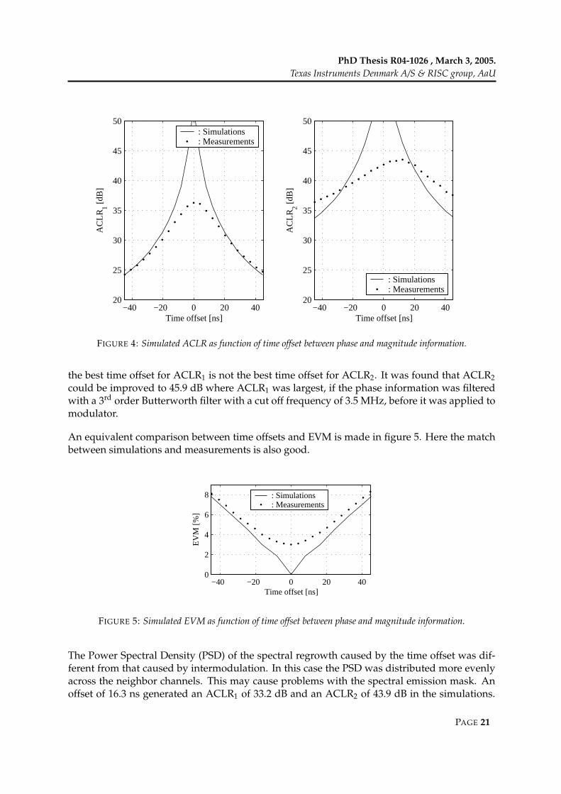
The polar modulator is sensitive to the same errors as the direct up-conversion transmitter,but it has the advantage that a power VCO, also known from GSM, may be used. This meansthat only limited gain is needed at RF, which means that the output noise may be reduced.Further more the remaining circuits only add little to ACLR if the amplitude information is ap-plied at the PA. However a timing offset between phase and amplitude information introducesnon-linearity and hence affects ACLR [20, 9]. In order to investigate this an experiment wasmade, where phase information was separated from amplitude information and converted toRF in a signal generator. The amplitude information was then added using a VGA with a veryshort settling time. ACLR and EVM were measured using signals where different time offsetswere introduced between phase and amplitude. The results for ACLR are shown in Figure 4,where they are compared to simulations conducted in MATLABTM. ACLR1 is averaged frommeasurements on channels±5 MHz from fC , while ACLR2 is averaged from measurements onchannels ±10 MHz from fC .
The simulations only includes timing offsets. It is seen that the simulations indicates closeto ideal behavior when no timing offsets are applied. The measurements shows significantACLR even at the optimal time offset, but as the time offset is increased, the measured ACLR1becomes increasingly close to the simulations. This indicates that the simulations are right, butthat other factors than time offsets are significant in the measurements. It is also noticed that
PAGE 20
PhD Thesis R04-1026 , March 3, 2005.Texas Instruments Denmark A/S & RISC group, AaU
−40 −20 0 20 4020
25
30
35
40
45
50
AC
LR1 [d
B]
Time offset [ns]
: Simulations: Measurements
−40 −20 0 20 4020
25
30
35
40
45
50
Time offset [ns]
AC
LR2 [d
B]
: Simulations: Measurements
FIGURE 4: Simulated ACLR as function of time offset between phase and magnitude information.
the best time offset for ACLR1 is not the best time offset for ACLR2. It was found that ACLR2could be improved to 45.9 dB where ACLR1 was largest, if the phase information was filteredwith a 3rd order Butterworth filter with a cut off frequency of 3.5 MHz, before it was applied tomodulator.
An equivalent comparison between time offsets and EVM is made in figure 5. Here the matchbetween simulations and measurements is also good.
−40 −20 0 20 400
2
4
6
8
Time offset [ns]
EV
M [%
]
: Simulations: Measurements
FIGURE 5: Simulated EVM as function of time offset between phase and magnitude information.
The Power Spectral Density (PSD) of the spectral regrowth caused by the time offset was dif-ferent from that caused by intermodulation. In this case the PSD was distributed more evenlyacross the neighbor channels. This may cause problems with the spectral emission mask. Anoffset of 16.3 ns generated an ACLR1 of 33.2 dB and an ACLR2 of 43.9 dB in the simulations.
PAGE 21

PER MADSEN
The resulting power spectrum (PS) is integrated over bands of 30 kHz or 1 MHz as specified inTable 3.2. In Figure 6 the integrated values are compared to the spectral emission mask definedin Table 3.2.
−10 −5 0 5 10
−30
−20
−10
0
10
Offset from fC [MHz]
PS
D [d
Bm
]: Mask: Signal
FIGURE 6: Simulated spectrum mask with time offset of 16.3 nS, which makes ACLR1 33.2 dB and ACLR2
43.9 dB. fC is the center frequency and the PSD is integrated over 30 kHz or 1 MHz, depending on the offset fromfC , as defined in [1].
It is seen that the mask is violated at -9 MHz from fC . This behavior means one should measureboth ACLR and spectrum emission mask when dealing with polar modulators.
The experiment has demonstrated that timing offsets between phase and amplitude informa-tion cause spectral regrowth. However the envelope was applied at RF by changing the gainin a VGA in this experiment. The most power efficient way to apply the envelope is to usea switched PA [20]. Switching is known from GSM to cause spectral regrowth as well, but itremains to see how much noise power this generates in the downlink band.
3-3 Conclusion
The direct up-conversion transmitter and polar modulator have been investigated. The polarmodulator has potential advantages when comes to output noise, but it remains to be seenhow a switched PA behaves outside the desired band. The presented experiment indicatesthat more factors than time offsets are important. The author therefore assesses that moreresearch needs to be done on polar modulators before all advantages and disadvantages withthis architecture can be uncovered. The direct up-conversion transmitter requires an RF filterto meet the requirements to noise in the Rx band. Monolithic filters have been a subject ofinvestigation for many years (see chapter 5). Therefore much information is available on thistopic, although most of the publications aim at applications in receivers.
Even though the polar modulator may become a relevant alternative in time, the direct up-conversion transmitter is the architecture that is best suited for integration on CMOS at thetime of writing. It is therefore decided to devote the remainder of the project to designing RFfilters on CMOS for use in the direct conversion transmitter.
PAGE 22

PhD Thesis R04-1026 , March 3, 2005.Texas Instruments Denmark A/S & RISC group, AaU
REFERENCES
[1] 3rd Generation Partnership Project (3GPP). UE radio transmission and reception (FDD), technical specification25.101 v.6.4.0, March 2004.
[2] Loke Aravind and Ali Fazal. Direct conversion radio for digital mobile phones - design issues, status andtrends. IEEE Transactions on Microwave Theory and Techniques, 50(11):2422 – 2435, November 2002.
[3] CTS Wireless Components, inc, Available at www.ctscorp.com. Model KFF6669A, 2001.[4] Ericsson. Comments to FDD UE transmission mask. TSGR4#6 (99)-394, July 1999.[5] Ericsson. Draft UE spectrum emission mask. Change request TSGR4#5 (99)-302, June 1999.[6] Ericsson. Revised UE spectrum emission mask. Change request TSGR4#6 (99)-390, July 1999.[7] Ericsson. UE modulation accuracy & peak code domain error. Change request TSGR4#10 (00)-0050, January
2000.[8] Fairchild Semiconductor, Available at www.fairchildsemi.com. Model RMPA2259, May 2004.[9] Yonghui Huang and Torben Larsen. A new polar transmitter for multimode wireless applications. In Proceed-
ings of the Nordic Radio Symposium, August 2004.[10] Michael B. Jenner. Signal quality degradation due to transmitter imperfections. RISC seminar 2002, December
2002.[11] Jae Ho Jung and Deuk Su Lyu. An architecture of reconfigurable transceiver based on digital IF for WCDMA
and IS-95 base stations. In The 5th International Symposium on Wireless Personal Multimedia Communications,volume 2, pages 831 – 834, October 2002.
[12] Hewlett Packard Ltd. Uplink and downlink modulation accuracy. Change request 3GPP/TSG R4#3 (99)107,March 1999.
[13] P. Madsen, T. Larsen, J. H. Mikkelsen, and J. C. Lindof. On the design of a differential common collectornegative resistance. In Proceedings of the 21st Norchip Conference, pages 100 – 103, Riga, Latvia, November 2003.Norchip, IEEE.
[14] Per Madsen. Simulating overall performance requirements for transmitters in IMT 2000 FDD user equipment.In Proceedings of the European Conference on Wireless Technology, Wireless Technologies 2001, pages 47 – 50, Lon-don, September 2001. European Microwave Week.
[15] Per Madsen. Simulation of EVM due to circuit imperfections in UMTS/FDD transmitters. In Proceedings of theNordic Matlab Conference 2003, pages 179 – 184, Copenhagen, October 2003. COMSOL.
[16] Per Madsen, Ole Kiel Jensen, Torben Amtoft, Ragner V. Reynisson, Jan H. Mikkelsen, Søren Laursen, Cris-tian R. Iversen, Troels E. Kolding, Torben Larsen, and Michael B. Jenner. RF requirements for UTRA/FDDtransceivers. In Proceedings of WPMC’ 01, volume 1, pages 197 – 202, Aalborg, Denmark, September 2001.Wireless Personal Multimedia Communications.
[17] Per Madsen, Ole Kiel Jensen, Torben Amtoft, Ragner V. Reynisson, Jan H. Mikkelsen, Søren Laursen, Troels E.Kolding, Torben Larsen, and Michael B. Jenner. UTRA/FDD RF transceiver requirements. Wireless PersonalCommunications, 1(23):55–66, 2002.
[18] M.H.Norris. Progressing from a UMTS radio demonstrator to commercial terminal design. In The Institutionof Electrical Engineers. IEE, Savoy Place, London, 1998.
[19] Murata Manufactoring, Available at www.murata.com. Model DFYK61G95LBJCA, September 2004.[20] Dietmar Rudolph. Kahn EER technique with single carrier digital modulations. IEEE Transactions on Microwave
Theory and techniques, 51(2):548 – 552, February 2003.[21] Skyworks, Available at www.skyworks.com. Model SKY77152, July 2004.[22] Jouko Vankka, Johan Sommarek, Jaakko Ketola, Ilari Teikari, and Kari A. I. Halonen. A digital quadrature
modulator with on-chip D/A converter. IEEE Journal of Solid State Circuits, 38(10):1635 – 1642, October 2003.[23] Olli Vaananen, Jouko Vankka, and Kari Halonen. Effect of baseband clipping in wideband CMDA system.
In IEEE, editor, Proceedings of the 7th Symposium on Spread Spectrum technology & Application, pages 445–449,Prauge, Czech Republic, September 2002.
[24] A.J. Yusof and M. Ismail. CMOS direct quadrature modulator for W-CDMA transmitter application. In Pro-ceedings of the 9th Asia-Pacific Conference on Communications, volume 2, pages 448 – 452. APCC 2003, September2003.
PAGE 23


PhD Thesis R04-1026 , March 3, 2005.Texas Instruments Denmark A/S & RISC group, AaU
4 FILTER TRANSFER FUNCTION
Chapter 3 investigates if direct conversion transmitter can be used for UMTS. It is found that anRF bandpass filter must be inserted in front of the PA to reduce transmitter noise in the UMTSRx band. This chapter investigates how the required attenuation may be obtained. The UMTSTx signal may mix with noise and create significant mixing products in the UMTS Rx bandwhen passed through the PA [5]. The filter must therefore suppress noise in both the UMTSRx band and the UMTS Rx image band. The UMTS Tx band is defined from 1920 MHz to1980 MHz, while the UMTS Rx band is defined from 2110 MHz to 2170 MHz [1]. The UMTSRx image band starts at 1670 MHz and ends at 1850 MHz. The filter must provide the gainand attenuation listed in Table 4.1 in these bands. The filter transfer function may also distortthe transmitted signal and thus add to the resulting EVM [6, 4]. The budget for EVM madein chapter 3 allows the filter and the DACs to generate a combined EVM of 14.8 %. There istherefore plenty of margin for EVM, but being the result of two unknown contributions, thiscan not be used to specify a requirement to the filter alone. However, the EVM generated bythe filter remains important and must be considered. The requirements to the filter are listed inTable 4.1.
TABLE 4.1: Recapitulation of filter requirements.Parameter Requirement UnitGain at 1920-1980 MHz > 3 dBAttenuation at 2110-2170 MHz > 12 dBAttenuation at 1670-1850 MHz > 12 dBNF in the UMTS Tx band < 10 dBNF in the UMTS Rx band < 15 dBNF in the UMTS Rx image band < 15 dBACLR ± 5 MHz > 45 dBACLR ± 10 MHz > 50 dB
Two different approaches to obtain the required attenuation are considered. Approach I in-volves maintaining the same filter transfer function no matter which Tx channel is used. Thisis illustrated in Figure 7a, where one filter transfer function is illustrated together with the PSDof modulated signals at three different center frequencies fC1−3. In approach II the center fre-quency of the filter is tuned to match the Tx channel in use. This is illustrated in Figure 7b,where the PSD of the modulated signals from Figure 7a are repeated again. Here the centerfrequency of the filter is changed to match those of the signals.
In both cases some frequency adjustment may be necessary because of tolerances of on-chipcomponents. The precision with which the frequency must be tuned may be different for thetwo approaches. This chapter investigates how the attenuation specified Table 4.1 can be ob-tained with the two approaches. Emphasis is put on:
• The number of resonators required to obtain the filter transfer function.
• The quality factor (Q) required in the resonators.
PAGE 25

PER MADSEN
FIGURE 7: Illustration of the two considered approaches. a: Approach I - the same filter transfer function is usedfor all transmit channels. b: Approach II - the filter transfer function is tuned to always provide maximal gain atthe transmit channel.
• The amount of EVM that results from the filter transfer function.
• Required frequency resolution and range of frequency adjustment.
In this thesis quality factor is defined as the ratio between center frequency and the half powerbandwidth [2, 3].
4-1 Approach I
In approach I the same filter transfer function is used for all the Tx channels. It is possible todesign filters with almost constant gain in the Tx band. However, such filters require higherorder than filters with inband gain fluctuation to provide the required attenuation. Therefore3 dB inband fluctuation is allowed in the filter transfer function although this may increaseEVM. The fluctuation is specified by upper and lower limits to the inband gain. This is illus-trated in Figure 8, where the maximum gain in the Tx band is increased to 6 dB and minimumgain is 3 dB as defined in Table 4.1. Figure 8 also shows the required 12 dB attenuation at theUMTS Rx and UMTS Rx image bands, but more attenuation is welcome here if available. Thefilter transfer function is therefore confined to the area marked with hatchings in Figure 8.
FIGURE 8: Requirements to filter transfer functions designed for approach I.
PAGE 26

PhD Thesis R04-1026 , March 3, 2005.Texas Instruments Denmark A/S & RISC group, AaU
4-1-1 Required Number of Resonators
Design of filters with standard transfer functions is described very well in text books [2, 7].The required order may be calculated from lowpass prototype transfer function approxima-tions, that transforms to bandpass transfer functions as described in [2, p. 72-74]. The resultingbandpass transfer function is symmetric around the center frequency. In this work the trans-formation is used to obtain lowpass prototype transfer functions approximations based on therequirements in Figure 8. However, to make the bandpass transfer function symmetrical, 12 dBattenuation is assumed at 2050 MHz instead of 2110 MHz. The required order of Butterworthand Chebyshev approximations are found using the procedures in [2, p. 38-48], and verifiedin MATLABTM. The results are listed in Table 4.2. Since the filter transfer functions must beimplemented with orders of integer numbers, the nearest integer above the calculated valuesare used.
TABLE 4.2: Order required of lowpass prototype approximations to provide the desired attenuation.Approximation type Order according to [2] Order according to MATLABTM
Butterworth 1.7 ≈ 2 2Chebyshev 1.5 ≈ 2 2
The 2nd order lowpass prototypes in Table 4.2 transform to 4th order bandpass filters. There aretwo ways of representing a bandpass transfer function in the s domain [2, 7]:
H(s) = G2∏
n=1
s
(s− pn) (s− p∗n)= G
2∏
n=1
s
s2 + sω0n
Qn+ ω2
0n
(4.1)
where pn and p∗n are complex conjugate poles that describe the transfer function of one res-onator. The nth set of poles is obtained from the nth pole in the lowpass prototype approxima-tion. G is a constant that adjusts the filter gain, ω0n - 2πf0n, where f0n is the centre frequencyand Qn is the quality factor of the nth resonator. Coefficients for the 2nd order lowpass pro-totype transfer functions are found in tables [2]. They are converted to the desired bandpasstransfer function using MATLABTM implementations of the transformations described in [2].
4-1-2 Required Q and Tolerances on Centre Frequencies
Section 4-1-1 shows that both 2nd order Butterworth and Chebyshev approximations providethe required attenuation. The fact that the calculated order is not an integer, indicates that thereis some tolerances on the filter bandwidth and centre frequency. This translates to toleranceson f0 and Q in the resonators. The tolerances are investigated through the cases listed in Ta-ble 4.3, where the f0 and Q required of each resonator is calculated for extreme cases usingMATLABTM.
Case (a) to (e) are all Butterworth bandpass approximations. Case (a) is the target function. Itis designed for a 3 dB bandwidth of 66 MHz. Cases (b) and (c) are designed for extremes of
PAGE 27

PER MADSEN
TABLE 4.3: f0 and Q of the of resonators for the investigated filter transfer functions.Case Center frequency [MHz] 3 dB BW [MHz] f01 [MHz] f02 [MHz] Q1 Q2
a 1950 66.0 1927 1973 41.8 41.8b 1950 60.0 1928.7 1971.1 45.9 45.9c 1950 72.6 1924.3 1975.6 38 38d 1953 66.0 1929.6 1976.2 41.8 41.8e 1947 66.0 1923.6 1970.2 41.7 41.7f 1950 ≈ 61.0 1929.6 1970.2 31.5 31.5g 1950 ≈ 74.5 1923.6 1976.2 39 39
3 dB bandwidth. Cases (d) and (e) are designed for extremes of center frequencies. In cases (g)and (f) the frequency tolerances from cases (d) and (e) are applied, so f0 of the two resonatorsare closest together (f) and furthest apart (g). In each case Eq. (4.1) is used to force the Q of theresonators to values that keep the transfer function in the area marked with hatchings in Figure8. The gain characteristic of transfer functions (a), (f) and (g) are plotted in Figure 9 togetherwith the limits defined in Figure 8.
1800 1850 1900 1950 2000 2050 2100−20
−15
−10
−5
0
5
f
g
a
Frequency [MHz]
Gai
n [d
B]
FIGURE 9: Gain characteristic of transfer functions (a),(f) and (g) implemented in MATLABTMas specified intable 4.3. The dashed lines represent the limits for the transfer functions specified in Figure 8.
The center frequency of the resonators changes approximately 6 MHz over the cases. Thiswould indicate that the frequency should be adjustable within 6 MHz. However, the Q mustbe regulated between 31.5 and 46 with unity precision in order to keep the transfer function inthe area marked with hatchings in Figure 8. The precision of Q may be relaxed if the precisionof the center frequency is increased.
PAGE 28

PhD Thesis R04-1026 , March 3, 2005.Texas Instruments Denmark A/S & RISC group, AaU
4-1-3 Estimated EVM
The transfer functions in section 4-1-2 are checked for EVM. The MATLABTM environment usedin [4] is used to simulate EVM for these transfer functions. The transfer functions must meetthe requirements at all extremes of f0 and Q. The simulations must therefore include all thecases in Table 4.3. In UMTS the raster on fC is 200 kHz [1]. Every possible value for fC shouldbe tested, but since the transfer functions change little over 200 kHz, the raster is increased to1 MHz in this investigation. The largest EVM is obtained in case (c) for fC equal to 1922 MHz.Here EVM is simulated to 2.9 % and estimated to 3.6 % using the approach described in [6].Therefore approach I is not expected to cause any problems with EVM.
4-2 Approach II
Recall that the purpose of the filter is to attenuate noise in the UMTS Rx and UMTS Rx imagebands. The most harsh requirements are made when the smallest obtainable duplex frequencyis used. This happens when the transmitter operates at the highest Tx channel, while the re-ceiver operates at the lowest Rx channel. In this case noise at 1850 MHz mixes to the Rx channel.In approach II it is acceptable to attenuate the part of the Tx band that is not used. This meansthat the 12 dB attenuation must be obtained 130 MHz from the pass band, in stead of 70 MHzas required in approach I.
4-2-1 Required Order
The concept of changing f0 with the carrier frequency allows for the use of filters with oneresonator of relative high Q or the use of several resonators with more moderate Q, operatingclose to the same frequency. The latter solution requires that the resonators are isolated fromone another to work efficiently. To enable comparison with approach I, transfer functions withboth one and two resonators are included in this investigation.
4-2-2 Required Q and Tolerances on Center Frequencies
The transfer function of a filter with one resonator may be expressed in the same manner asthe transfer function with two resonators in Eq. (4.1). This representation enables the designof a transfer function from the knowledge of desired f0 and Q alone. The transfer functionsare designed in the MATLABTM environment used in section 4-1. The gain characteristics ofseveral transfer functions with one resonator are shown in Figure 10. These transfer functionsare designed with f0 at (a) 1922 and (b) 1978 MHz. Tolerances of 3 MHz are added to f0 at1978 MHz. Both the gain and Q are adjusted so an average gain of 3 dB and the requiredattenuation is obtained. It appears that a Q of 45 is required to achieve this.
Transfer function (a) must provide at least 12 dB of attenuation at 1730 MHz. This is achievedwith the suggested Q. Similar investigations are made for a filter transfer function that employstwo resonators operating at the same frequency. Again a tolerance of 3 MHz is allowed on f0
and Q are adjusted until the required attenuation is obtained for fC equal to 1978 MHz. In this
PAGE 29

PER MADSEN
1750 1800 1850 1900 1950 2000 2050 2100−20
−15
−10
−5
0
5
Frequency [MHz]
Gai
n [d
B]
a b
FIGURE 10: Gain of transfer functions using only one resonator. Dotted lines indicated functions that implementstolerance on f0. Dashed lines indicate limits specified in Figure 8.
case a Q of 17.5 provides the required attenuation. The Q found for transfer functions withboth one and two resonators represent minimum requirements. Less strict tolerances may beobtained if higher Q values are used.
4-2-3 Estimated EVM
The MATLABTM environment used in Section 4-1 is also used to estimate EVM of the transferfunctions suggested here. The transfer functions do not change much in the desired band,as fC is shifted. Significant differences in EVM are therefore only expected when frequencytolerances are applied. The simulations are therefore restricted to transfer functions designedfor fC of 1978 MHz. EVM is simulated and estimated to less than 1 % using [6] with 3 MHzfrequency tolerances. This approach will therefore not cause significant contributions to EVM.
4-3 Conclusion
This chapter investigates the design of filter transfer functions that provide the attenuation re-quired in the system analysis in Chapter 3. Approaches where the transfer function is keptconstant and where it is tuned to match the carrier frequency are investigated. The first ap-proach requires two resonators with Q up to 46. The second approach requires one resonatorwith a Q of 45. In both cases f0 must be tunable with a precision better than 6 MHz. Thesecond approach offers a solution that uses half the resonators. Requirements to noise andACLR should therefore also be easier to meet with this solution. The penalty for is this tuningrange. Both resonators must have tuneable center frequencies because of device tolerances, butthe second approach has to add at least 60 MHz to that in order to follow the carrier of the sig-nal. None of the approaches are expected to generate significant amounts of EVM. The choicemust therefore be made according to the penalties for generating the required Q and what thetolerances are on the CMOS devices used in the resonators.
PAGE 30

PhD Thesis R04-1026 , March 3, 2005.Texas Instruments Denmark A/S & RISC group, AaU
REFERENCES
[1] 3rd Generation Partnership Project (3GPP). UE radio transmission and reception (FDD), technical specification25.101 v.6.4.0, March 2004.
[2] Lawrence P. Huelsman. Active and Passive Analog Filter Design. ISBN 0-07-112519-1. McGraw Hill, Singapore,1993.
[3] Herbert L. Krauss, Charles W. Bostian, and Frederick H. Raab. Solid State Radio Engineering. ISBN 0-471-03018-X.John Wiley & Sons, 1980.
[4] Per Madsen. Simulation of EVM due to circuit imperfections in UMTS/FDD transmitters. In Proceedings of theNordic Matlab Conference 2003, pages 179 – 184, Copenhagen, October 2003. COMSOL.
[5] Per Madsen, Ole Kiel Jensen, Torben Amtoft, Ragner V. Reynisson, Jan H. Mikkelsen, Søren Laursen, Cristian R.Iversen, Troels E. Kolding, Torben Larsen, and Michael B. Jenner. RF requirements for UTRA/FDD transceivers.In Proceedings of WPMC’ 01, volume 1, pages 197 – 202, Aalborg, Denmark, September 2001. Wireless PersonalMultimedia Communications.
[6] D. Pimingsdorfer, A. Holm, G. Fishcerauer, R. Thomas, A. Springer, and R. Weigel. Impact of SAW RF and IFFilter Characteristics on UMTS Transceiver System Performance. IEEE Ultrasonics Symposium, pages 365–368,January 1999.
[7] Arthur B. Williams and Fred J. Taylor. Electric Filter Design Handbook. ISBN 0-07-070441-4. McGraw-Hill, NewYork, USA, 3rd edition, 1995.
PAGE 31


PhD Thesis R04-1026 , March 3, 2005.Texas Instruments Denmark A/S & RISC group, AaU
5 RESONATORS
This chapter investigates the implementation of resonators for low noise and distortion appli-cations. Chapter 4 concludes that a Q up to 46 is required in order to achieve the attenuationspecified in chapter 3. The investigation presented here is based on a literature study anddocuments achievements so far. The literature considers gyration-C, recursive resonators andQ-enhanced LC resonators for use in radio frequency filters. First their functionality is de-scribed and then a comparison of theoretical dynamic range of the different resonator types ispresented.
5-1 Implementation of resonators
This subsection presents the three types of resonators considered in the literature.
5-1-1 Q-enhancement
In Q-enhancement losses in resonators are compensated by adding a circuit with a negativeimpedance. Q-enhancement may be applied to single components or larger circuits like theone illustrated in Figure 11a. Ideally this resonator has infinitely high Q, but losses in theinductors and resistive loads limit the achievable Q. In Figure 11a losses are modelled witha parallel conductance G0. Ignoring for a moment YNE the total impedance of the resonatorcircuit is [12]:
Z(ω) =jω
1C
(jw)2 + jωG0
C+
1LC
(5.1)
where ω = 2πf . The center frequency and Q in this LC resonator are found by [12]:
ω0 =
√1
LC= 2πf0 (5.2)
Q0 =ω0C
G0=
1G0ω0L
(5.3)
where ω0 = 2πf0 and f0 is the resonance frequency of the LC resonator. Assuming that YNE hasthe conductance: −GNE and no reactive part, the effective Q at f0 can be found by substitutingG0 with G0 −GNE in Eq. (5.3).
Literature reports implementations of YNE with transistors in the configurations illustrated inFigures 11b to h [9, 3, 17, 14, 8, 19, 16, 4, 21, 13, 5, 2]. FETs are used as in this section, but thecircuits also work with BJTs. If only the trans-conductance (gm) of the transistors is considered,the input admittance of the circuits in Figure 11b and c is [9]:
YNEb,c=
1ZNE
=1
Z1 + Z2 + gmZ1Z2(5.4)
It is seen that ZNE has a negative real part if Z1 and Z2 have of the same type of reactance i.e. in-ductive or capacitive [17, 9, 3]. Although [3, 17] describe these circuits, actual implementations
PAGE 33

PER MADSEN
FIGURE 11: a: LC resonator with losses and Q-enhancement. b to h: Examples of negative trans-conductanceimplemented using FETs [9, 3, 17, 14, 8, 19, 16, 4, 21, 13, 5, 2].
are reported in [14, 8]. The admittance of the circuits in Figure 11d, e and f is [9, 8]:
YNEd,c,e=
1Z1 + Z2
+gmZ2
Z1 + Z2= [Z1 + Z2]
−1 +[
1gm
(1 +
Z1
Z2
)]−1
(5.5)
The circuits only produce negative conductance if Z1 and Z2 represent reactance of differenttypes and if |Z1| > |Z2|.
The circuits presented so far use reactive components to help generate the negative admittance.This means that the admittance also has a reactive part and that the negative conductancechanges with frequency. Figures 11g and h show examples of how a negative conductancemay be obtained without the use of reactive components. Assuming that the two transistorsare perfectly identical the admittance is [9]:
YNEg,h= −gm
2(5.6)
While the circuit in Figure 11g implements a single-ended negative admittance, the circuit inFigure 11h implements a differential negative admittance. The circuit in Figure 11h is by far themost popular and different versions are found in [16, 4, 21, 13, 5, 2, 9]. Most of these referencesreport performance of filters rather than LC-tanks. The center frequencies are 800 - 2400 MHzwhere Q of 50 - 400 are reported in single resonator filters, but only [21, 2] use CMOS. Here Qsof 80 at 830 MHz and 50 at 1800 - 2400 MHz are reported.
5-1-2 Gyration-C
Filters implemented using gyration-C (also referred to as gm-C) resonators are quite popularin the literature [9, 10, 6, 11, 20, 22, 18]. The great advantage of this type of implementation isthat no on-chip inductors are required. This saves die area and makes the circuit cheaper tomanufacture than LC resonators. The inductive part is generated through impedance transfor-mation of a capacitance. Figure 12 illustrates how a resonator may be designed from an ideal
PAGE 34

PhD Thesis R04-1026 , March 3, 2005.Texas Instruments Denmark A/S & RISC group, AaU
gyration-C circuit. The gyration-C circuit is marked by the dashed box in Figure 12. It consistsof minimum two trans-conductances, denoted gm1 and gm2, and one capacitor denoted Cg. Cis the capacitive part of the resonator and RL is a resistive load.
FIGURE 12: Resonator circuit implemented using a simple gyration-C circuit. The dashed box marks the gyration-C circuit.
The impedance of the gyration-C circuit is:
Zg =jωCg
gm1gm2(5.7)
From Eq. 5.7 it is seen that the ideal gyration-C circuit generates an inductance Lg equal toCg/(gm1gm2) and an infinitely high Q [22, 10]. The gyration-C circuit is sensitive to parasiticsin the transistors [18, 22, 20] and un-intended phase shifts [10]. Such imperfections limit theachievable Q [18, 22, 10] and a possible resistive load decreases the Q of the resonator further.Assuming that the resistive load is the major contributor to Q degradation, the impedance ofthe resonator in Figure 12 is:
Z(ω) =jω
1C
(jw)2 + jω1
RLC+
gm1gm2
CgC
(5.8)
and ω0 and Q for a gyration-C resonator are therefore:
ω0 =√
gm1gm2
CgC(5.9)
Q =√
gm1gm2
CgCCRL (5.10)
For gm =√
gm1gm2 and Cg = C, ω0 and Q reduces to gm/C and gmRL respectively. The trans-conductance thus influence both the center frequency and Q in this resonator.
Reports of successful implementations are rare. [9] reports Q of 1000, achieved in a narrowband at 4.8 GHz using GaAs-MESFETs and a Q from 30-200 achieved from 1.5 GHz to 1.8 GHzin a GaAs HBT process. In both cases Q is calculated from the equivalents to Zg in Figure 12,measured with S-parameters. No RF implementations on CMOS are reported, but [20] reportssimulated Q of 41 at 900 MHz in a 0.35 µm CMOS process.
PAGE 35

PER MADSEN
5-1-3 Recursive Filters
Recursive filters use feedback and gain stages to generate the transfer function of a resonator.Gain stages are most often represented with Operational Trans-conductance Amplifiers (OTAs)in the literature [7, 1, 15]. [7] holds an extensive analysis of Recursive filters implemented byOTAs. A difference OTA is defined as shown in Figure 13a [7, p 349]. Figure 13b-e showfour different ways to implement a second order bandpass resonator using the OTA defined inFigure 13a. The resonator in Figure 13b employs a passive resonator circuit in the feedback pathwith an impedance of ZR. The remaining resonators are all build from a general Tow-Thomasfilter structure [7, p 354-356].
FIGURE 13: a: simplified model for the used OTA. b-e: four examples of recursive filters implemented byOTA blocks.
The transfer function of the resonator in Figure 13b is:
Hb(ω) =VOUT (ω)VIN (ω)
= ZR(ω)gm + 1 (5.11)
If the non-compensated LC resonator, introduced in subsection 5-1-1, is used as feedback cir-cuit, ZR is equal to Eq. (5.1) and the transfer function is:
Hb(ω) =(jω)2 + jω
1C
(G0 + gm) +1
LC
(jω)2 + jωG0
C+
1LC
(5.12)
It is not possible to obtain less than unity gain with Hb(ω). This means that attenuation onlycan be obtained with this filter, if it is applied before or after the resonator.
The problem of limited attenuation is not seen in the resonators in Figure 13c, d and e. The
PAGE 36

PhD Thesis R04-1026 , March 3, 2005.Texas Instruments Denmark A/S & RISC group, AaU
transfer function for these implementations may be expressed by [7, p 356]:
Hn(ω) =Nn(ω)
(jω)2 + jωgm3
C2+
gm1gm2
C1C2
(5.13)
where n refers to the name of the circuit in Figure 13 and Nn for the respective circuits are:
Nc(ω) = jωgm2
C2, Nd(ω) = jω
gm1
C1, Ne(ω) = jω
gm3
C2
According to [7], the nominator of circuit c should be the same as that for circuit b. However,analytical calculations verified in HP-ADS have shown that this is not the case. These circuitsgenerate a bandpass transfer function with only one pole at f = 0. Notice the circuit in thedashed boxes in Figure 13c and d. This circuit is equivalent to a resistance of 1/gm3 Ω [7, p 356].In Figure 13c this circuit may be replaced by the load resistance RL to ground. In this case gm3
may be replaced with 1/RL in Eq. (5.13). Hereby the denominator in Eq. (5.8) is obtained. Sinceall the circuits share the same denominator, ω0 and Q for all the circuits are:
ω0 =√
gm1gm2
C1C2(5.15)
Q =C2
gm3
√gm1gm2
C1C2(5.16)
Notice that gm =√
gm1gm2 and C1 = C2 means that ω0 = gm/C1,2 and Q = gm/gm3. Thisresembles ω0 and Q of the gyration-C resonators described in subsection 5-1-2. Q is henceclosely linked to the center frequency and gain of these filters.
The only literature found, that report implementations of recursive filters, use the type illus-trated in Figure 13b [1, 15]. However, the feedback path consists of a more complicated circuitthan the LC resonator used in the example above. [1] reports a Q of 14.9-16.6 in combinationwith a gain of 7.5-6.5 dB at 5.2-5.6 GHz in a 0.18 µm CMOS process .
5-2 Noise and Dynamic Range
Noise performance is important for the filters function in the transmitter. A noise budget ismade in chapter 3, that specifies a maximal inband noise figure of 10 dB. The noise figure of agyration-C resonator is [10, 9]:
NFgmC = 1 + 4γQ (5.17)
if gm1 = gm2, C1 = C2 and γ is the noise gamma effect of the transistors [9]. The noise figurefor a Q-enhanced LC resonator is [9]:
NFQenh = 1 + 2Q
Q0(1 + rn, gn) (5.18)
where Q0 is the un-compensated Q, and rn and gn are the relative noise resistance and ad-mittance respectively of the Q-enhancement circuit [9]. They indicate how much noise the
PAGE 37

PER MADSEN
circuit generates compared to a passive resonator with equivalent Q [9]. rn and gn depend onboth the gamma effect in the transistors used on the Q-enhancement circuit and on how theQ-enhancement circuit is implemented [9].
So far the focus has been on noise. Another benchmark that is discussed in the literature isdynamic range. Although different approaches are used in the literature, the same major con-clusions are reached. According to [6] the best dynamic range achievable in bi-quads, such asthe ones used in gyration-C and recursive resonators in Figure 13c to e, is:
DRgmC =v2maxC
4kTξ
1Q
(5.19)
where vmax is the maximum non-saturated average voltage over the capacitors, k is Boltzman’sconstant, C is the total capacitance, distributed equally among C1 and C2, T is temperature inKelvin, ξ is the noise factor of the gain stages, and Q is the loaded quality factor. An expressionfor the dynamic range of a Q-enhanced LC filter is reported as [11]:
DRQenh =v2maxC
4kTξ
Q0
Q(5.20)
The parameters are the same as used in Eq. (5.19), except for ξ, which in this case takes into ac-count differences in implementation of the negative resistance. Furthermore the un-compensatedQ in the LC circuit Q0 is introduced.
The investigations presented in [6, 11, 10, 9] are all very superficial. They use a simple transistormodel that combines all noise effects to one noise current source at the transistor output. Thenoise current depends on gm in the transistor and the gamma effect, which takes into accountdifferences in substrate and transistor type. Further more the upper limit of dynamic range isspecified by some voltage, which is difficult to relate to specific linearity performance in thetransistor. It is, however, beyond the scope of this work to remedy this. In spite of crude mod-elling, the reported investigations manage to show simple correlations between noise, dynamicrange and Q.
5-3 Conclusion
This section investigates different types of resonators presented in the literature. Q-enhancedresonators or resonators with gyration-C inductors may both generate the required Q, whilerecursive filters may have difficulties in providing the required Q at the required frequencywhile maintaining a usable gain. This leaves the Q-enhanced LC resonator and the gyration-Cresonator as suitable choices. Q-enhanced resonators are shown to have a theoretical noise per-formance that is superior to the gyration-C resonator. The Q-enhances LC resonator is thereforeselected for the application in the UMTS Tx filter.
REFERENCES
[1] Win Chaivipas, Magnus Denestig, Mohammed Ismail, and Henrik Johnson. An RF active filter with on-chiptuning in CMOS. In Procedings of the 21st Norchip Conference, volume 1, pages 20 – 23. Norchip, IEEE, November2003.
PAGE 38

PhD Thesis R04-1026 , March 3, 2005.Texas Instruments Denmark A/S & RISC group, AaU
[2] Kare T. Christensen, Thomas H. Lee, and Erik Bruun. A high dynamic range programmable 1850 MHz to 2400
MHz front-end filter in 0.25 µm CMOS. In Proceedings of the 21st Norchip Conference, volume 1, pages 16 – 19.Norchip, IEEE, November 2003.
[3] D.Li and Y. Tsividis. Active LC filters on silicon. In IEE Proceeding of Circuits Devices Systems I, volume 147,pages 49 – 56, February 2000.
[4] Ralph Duncan, Kenneth W. Martin, and Adel S Sedra. A Q-Enhanced active-RLC bandpass filter. IEEE Trans-actions on Circuits and Systems-II: Analog and Digital Signal Processing, 44(5):341 – 347, May 1997.
[5] Weinann Gao and W. Martin Snelgrove. A linear integrated LC bandpass filter with Q-Enhancement. IEEETransactions on Circuits and Systems II: Analog and Digital Signal Processing, 45(5):635 – 639, May 1998.
[6] Gert Groenewold. The design of high dynamic range continuous-time integrateable bandpass filters. Transac-tions on Circuits and Systems, 38(9):838 – 852, August 1991.
[7] Lawrence P. Huelsman. Active and Passive Analog Filter Design. ISBN 0-07-112519-1. McGraw Hill, Singapore,1993.
[8] Ulun Karacaoglu and Ian D. Robertson. MMIC active bandpass filters using varactor-tuned negative resistanceelements. Transactions on Microwave Theory and Techniques, 43(12):2926 – 2932, December 1995.
[9] Risto Kaunisto. Monolithic Active Resonator Filters for High Frequencies. PhD thesis, Helsinki University ofTechnology, 2000.
[10] Risto Kaunisto, Kari Stadius, and Veikko Porra. A 3 GHz silicon-BJT resonator and filter. In Proceedings of the1998 IEEE International Conference on Electronics, volume 3, pages 197 – 200. Circuits and Systems, September1998.
[11] W.B. Khun, F.W. Stephensson, and A. Elshabini-Riad. Dynamic range of high-Q OTA-C and enhanced-Q LCRF bandpass filter. In Proceedings of the 37th Midwest Symposium on Circuits and Systems, volume 2, pages 767 –771. Circuits and System, IEEE, August 1994.
[12] Herbert L. Krauss, Charles W. Bostian, and Frederick H. Raab. Solid State Radio Engineering. ISBN 0-471-03018-X. John Wiley & Sons, 1980.
[13] William B. Kuhn, Naveen K. Yanduru, and Adam S. Wyszynski. A high dynamic range digitally tuned Q-Enhanced LC bandpass filter for cellular/PCS receivers. In Proceedings of the Radio Frequency Integrated Circuits(RFIC) Symposium, pages 261 – 264. IEEE, June 1998.
[14] Kwok-Keung, M-Cheng, and Hil-Yee Chan. Noise performance of negative-resistance compensated mi-crowave bandpass filters – theory and experiments. IEEE Transactions on Microwave Theory and Techniques,49(5):924 – 927, May 2001.
[15] W. Mouzannar, L. Billonnet, B Jarry, and P.Guillon. Hilghly selective novel MMIC micrwave active recursivefilter. In Radio Frequency Integrated Circuits Symposium, pages 39 – 41. IEEE, 1998.
[16] Spyros Pipilos, Yannis P. Tsividis, Josef Fenk, and Yannis Papanaos. A Si 1.8 GHz RLC filter with tuneablecentre frequency and quality factor. Journal of Solid state Circuits, 31(10):1517 – 1525, October 1996.
[17] Theerachet Soorapanth and S. Simon Wong. A 0 dB-IL, 2140±30 MHz bandpass filter utilizing Q-enhancedspiral inductors in standard CMOS. Journal of Solid State Circuits, 37(5):579 – 586, May 2002.
[18] Apinunt Thanachayanont. A 1.5-V CMOS fully differential inductorless RF bandpass amplifier. In The 2001IEEE International Symposium on Circuits and Systems, volume 1, pages 49 – 52. ISCAS 2001, May 2001.
[19] Hann-Haur Wu and Yi-Jen Chan. Tunable high-Q MMIC active filter by negative resistance compensation. InTechnical Digest 1997, editor, 19th Annual, Gallium Arsenide Integrated Circuit (GaAs IC) Symposium, pages 252– 255, October 1997.
[20] Y. Wu, X. Ding, and M. Ismael H. Olsson. Inductor less CMOS RF bandpass filter. Electronics Letters, 73(16):1027– 1029, August 2001.
[21] William S. T. Yan, Ricky K. C. Mak, and Howard C. Luong. 2-V 0.8 µM CMOS monolithic RF filter for GSMreceivers. In Microwave Symposium Digest, volume 2, pages 572 – 596. IEEE MTT S International, June 1999.
[22] W. Zhuo, J. Pineda de Gyvez, and E. Sánchez-Sinencio. Programmable low noise amplifier with active inductorload. In Proceedings of the 1998 IEEE International Symposium on Circuits and Systems, volume 4, pages 365 – 368.ISCAS’98, May - June 1998.
PAGE 39

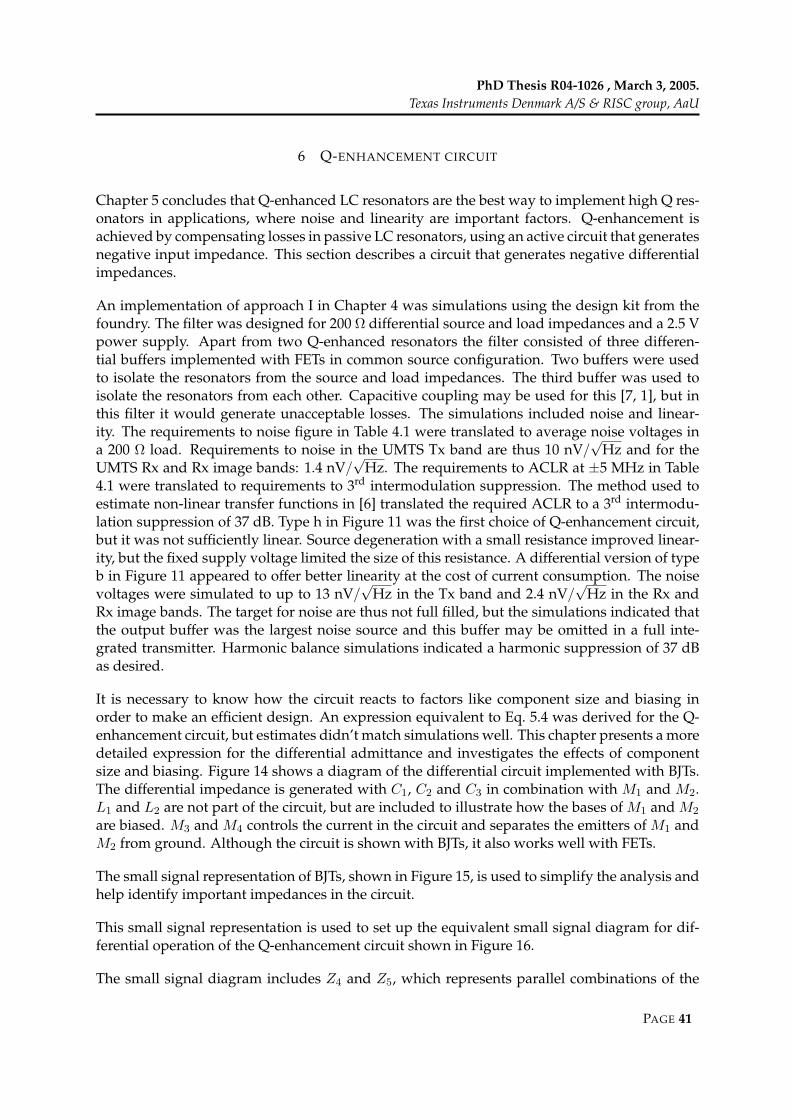
PhD Thesis R04-1026 , March 3, 2005.Texas Instruments Denmark A/S & RISC group, AaU
6 Q-ENHANCEMENT CIRCUIT
Chapter 5 concludes that Q-enhanced LC resonators are the best way to implement high Q res-onators in applications, where noise and linearity are important factors. Q-enhancement isachieved by compensating losses in passive LC resonators, using an active circuit that generatesnegative input impedance. This section describes a circuit that generates negative differentialimpedances.
An implementation of approach I in Chapter 4 was simulations using the design kit from thefoundry. The filter was designed for 200 Ω differential source and load impedances and a 2.5 Vpower supply. Apart from two Q-enhanced resonators the filter consisted of three differen-tial buffers implemented with FETs in common source configuration. Two buffers were usedto isolate the resonators from the source and load impedances. The third buffer was used toisolate the resonators from each other. Capacitive coupling may be used for this [7, 1], but inthis filter it would generate unacceptable losses. The simulations included noise and linear-ity. The requirements to noise figure in Table 4.1 were translated to average noise voltages ina 200 Ω load. Requirements to noise in the UMTS Tx band are thus 10 nV/
√Hz and for the
UMTS Rx and Rx image bands: 1.4 nV/√
Hz. The requirements to ACLR at ±5 MHz in Table4.1 were translated to requirements to 3rd intermodulation suppression. The method used toestimate non-linear transfer functions in [6] translated the required ACLR to a 3rd intermodu-lation suppression of 37 dB. Type h in Figure 11 was the first choice of Q-enhancement circuit,but it was not sufficiently linear. Source degeneration with a small resistance improved linear-ity, but the fixed supply voltage limited the size of this resistance. A differential version of typeb in Figure 11 appeared to offer better linearity at the cost of current consumption. The noisevoltages were simulated to up to 13 nV/
√Hz in the Tx band and 2.4 nV/
√Hz in the Rx and
Rx image bands. The target for noise are thus not full filled, but the simulations indicated thatthe output buffer was the largest noise source and this buffer may be omitted in a full inte-grated transmitter. Harmonic balance simulations indicated a harmonic suppression of 37 dBas desired.
It is necessary to know how the circuit reacts to factors like component size and biasing inorder to make an efficient design. An expression equivalent to Eq. 5.4 was derived for the Q-enhancement circuit, but estimates didn’t match simulations well. This chapter presents a moredetailed expression for the differential admittance and investigates the effects of componentsize and biasing. Figure 14 shows a diagram of the differential circuit implemented with BJTs.The differential impedance is generated with C1, C2 and C3 in combination with M1 and M2.L1 and L2 are not part of the circuit, but are included to illustrate how the bases of M1 and M2
are biased. M3 and M4 controls the current in the circuit and separates the emitters of M1 andM2 from ground. Although the circuit is shown with BJTs, it also works well with FETs.
The small signal representation of BJTs, shown in Figure 15, is used to simplify the analysis andhelp identify important impedances in the circuit.
This small signal representation is used to set up the equivalent small signal diagram for dif-ferential operation of the Q-enhancement circuit shown in Figure 16.
The small signal diagram includes Z4 and Z5, which represents parallel combinations of the
PAGE 41

PER MADSEN
FIGURE 14: Differential implementation of the type b Q-enhancement circuit shown in Figure 11, section 5.
FIGURE 15: Small signal representation of a BJT. The same basic representation is used for FETs.
output impedances of the transistors. It will be shown later that these impedance are signif-icant. The small-signal diagram is used to derive expressions for the differential admittance.Eq. (6.1) is a simplified expression, where Z4 and Z5 are omitted.
YINs =1
(ZµM1 + ZµM2) ‖(
Z1 + Z3 + Z2 +12
(Z2Z1yM1 + Z2Z3yM2)) (6.1)
This expression has the level of detail reported in the literature for the single ended versions.If transistors are used, where only the trans-conductance gm is significant and the circuit issymmetrical, the differential conductance at the frequency f reduces to: −gm
21
(2πf)2C1C2, while
the differential reactance reduces to a series connection of C1, C2 and C3.
Eq. 6.2 is a more detailed expression for the differential admittance that includes Z4 and Z5 andhence the output impedance the transistors.
YINc =1
(ZµM1 + ZµM2) ‖(
Z1 + Z3 +Z2 (Z4 + Z5) + yM1Z1Z4 + yM2Z3Z5
Z3 + Z4 + Z5
) (6.2)
Refer to [4, 5] for details on how the small signal transistor representation is used in Eqs. 6.1and 6.2. In the following the expressions are used to analyse the Q-enhancement circuit in
PAGE 42
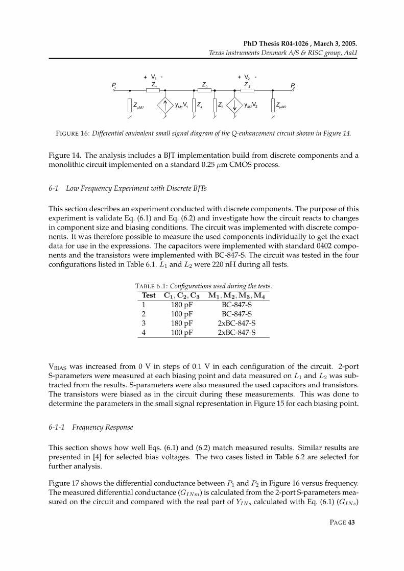
PhD Thesis R04-1026 , March 3, 2005.Texas Instruments Denmark A/S & RISC group, AaU
FIGURE 16: Differential equivalent small signal diagram of the Q-enhancement circuit shown in Figure 14.
Figure 14. The analysis includes a BJT implementation build from discrete components and amonolithic circuit implemented on a standard 0.25 µm CMOS process.
6-1 Low Frequency Experiment with Discrete BJTs
This section describes an experiment conducted with discrete components. The purpose of thisexperiment is validate Eq. (6.1) and Eq. (6.2) and investigate how the circuit reacts to changesin component size and biasing conditions. The circuit was implemented with discrete compo-nents. It was therefore possible to measure the used components individually to get the exactdata for use in the expressions. The capacitors were implemented with standard 0402 compo-nents and the transistors were implemented with BC-847-S. The circuit was tested in the fourconfigurations listed in Table 6.1. L1 and L2 were 220 nH during all tests.
TABLE 6.1: Configurations used during the tests.Test C1,C2,C3 M1,M2,M3,M4
1 180 pF BC-847-S2 100 pF BC-847-S3 180 pF 2xBC-847-S4 100 pF 2xBC-847-S
VBIAS was increased from 0 V in steps of 0.1 V in each configuration of the circuit. 2-portS-parameters were measured at each biasing point and data measured on L1 and L2 was sub-tracted from the results. S-parameters were also measured the used capacitors and transistors.The transistors were biased as in the circuit during these measurements. This was done todetermine the parameters in the small signal representation in Figure 15 for each biasing point.
6-1-1 Frequency Response
This section shows how well Eqs. (6.1) and (6.2) match measured results. Similar results arepresented in [4] for selected bias voltages. The two cases listed in Table 6.2 are selected forfurther analysis.
Figure 17 shows the differential conductance between P1 and P2 in Figure 16 versus frequency.The measured differential conductance (GINm) is calculated from the 2-port S-parameters mea-sured on the circuit and compared with the real part of YINs calculated with Eq. (6.1) (GINs)
PAGE 43

PER MADSEN
TABLE 6.2: ICC in Figure 14 in mA measured during the tests (adjusted via VBIAS in Figure 14).Case Test 1 & 2 Test 3 & 4
a 6.8 11.0b 27.4 44.7
and the real part of YINc calculated with Eq. (6.2) (GINc).
20 40 60 80 100−10
−8
−6
−4
−2
0
2
Diff
eren
tial C
ondu
ctan
ce [m
S]
a
b
Test 1
GINm
GINc
GINs
20 40 60 80 100−10
−8
−6
−4
−2
0
2
a
b
Test 2
GINm
GINc
GINs
20 40 60 80 100−15
−10
−5
0
Diff
eren
tial C
ondu
ctan
ce [m
S]
a
b
Test 3
Frequency [MHz]
GINm
GINc
GINs
20 40 60 80 100−15
−10
−5
0
Frequency [MHz]
a
b
Test 4
GINm
GINc
GINs
FIGURE 17: Differential conductance between P1 and P2 in Figure 16 vs. frequency for tests 1 to 4 in Table 6.1.GINm is the measured conductance, GINs is estimated using Eq. (6.1) and GINc is estimated using Eq. (6.2).
It is seen that Eq. (6.1) estimates the differential conductance worse than Eq. (6.2) in all thetests. Z4 and Z5 are therefore significant in this circuit. It is further noticed that a distinctnotch appears between 10 MHz and 40 MHz depending on biasing, capacitance and numberof transistors. This notch appears because the transistor’s trans-admittance has a significantreactive part.
PAGE 44
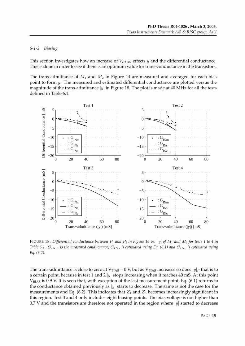
PhD Thesis R04-1026 , March 3, 2005.Texas Instruments Denmark A/S & RISC group, AaU
6-1-2 Biasing
This section investigates how an increase of VBIAS effects y and the differential conductance.This is done in order to see if there is an optimum value for trans-conductance in the transistors.
The trans-admittance of M1 and M2 in Figure 14 are measured and averaged for each biaspoint to form y. The measured and estimated differential conductance are plotted versus themagnitude of the trans-admittance |y| in Figure 18. The plot is made at 40 MHz for all the testsdefined in Table 6.1.
0 20 40 60 80−20
−15
−10
−5
0
5Test 1
Diff
eren
tial C
ondu
ctan
ce [m
S]
: GINm
: GINs
: GINc
0 20 40 60 80−20
−15
−10
−5
0
5Test 2
: GINm
: GINs
: GINc
0 20 40 60 80−20
−15
−10
−5
0
5Test 3
Trans−admittance (|y|) [mS]
Diff
eren
tial C
ondu
ctan
ce [m
S]
: GINm
: GINs
: GINc
0 20 40 60 80−20
−15
−10
−5
0
5Test 4
Trans−admittance (|y|) [mS]
: GINm
: GINs
: GINc
FIGURE 18: Differential conductance between P1 and P2 in Figure 16 vs. |y| of M1 and M2 for tests 1 to 4 inTable 6.1. GINm is the measured conductance, GINs is estimated using Eq. (6.1) and GINc is estimated usingEq. (6.2).
The trans-admittance is close to zero at VBIAS = 0 V, but as VBIAS increases so does |y|,- that is toa certain point, because in test 1 and 2 |y| stops increasing when it reaches 40 mS. At this pointVBIAS is 0.9 V. It is seen that, with exception of the last measurement point, Eq. (6.1) returns tothe conductance obtained previously as |y| starts to decrease. The same is not the case for themeasurements and Eq. (6.2). This indicates that Z4 and Z5 becomes increasingly significant inthis region. Test 3 and 4 only includes eight biasing points. The bias voltage is not higher than0.7 V and the transistors are therefore not operated in the region where |y| started to decrease
PAGE 45

PER MADSEN
in test 1 and 2. It is therefore concluded that decrease in differential conductance observed intests 1 and 2 does not represent general behavior of the Q-enhancement circuit. Instead it is aresult of the transistors being operated with decreasing efficiency.
6-1-3 Choice of Capacitance
This section investigates if one particular choice of capacitance is better than others. AlthoughEq. (6.1) overestimates the Q-enhancement capabilities, Figure 17 shows that it predicts thecorrect frequency of the notch. This indicates that the notch has something to do with thetrans-admittance of M1 and M2. Eq. (6.1) is therefore used to establish a connection betweentrans-admittance (y) and capacitance. It is sufficient to use the average of the capacitance (Ca)together with y. A simplified expression for the differential conductance is:
GINe(f) = Re
− 1
y
(2πfCa)2 + j
32πfCa
(6.3)
= − (2πfCa)2 Rey(f)
(Rey(f))2 + (Imy(f)+ 6πfCa)2(6.4)
Eq. (6.2) is used to plot the differential conductance as a function of capacitance in [4]. Figure 19repeats this and compares the notches with the results from Eq. (6.4) in order to shown that thisexpression estimates the notch correctly. The example uses the biasing conditions from table6.2 and results are shown for operation at 40 MHz. As might be expected Eq. (6.4) estimatesthe differential conductance much lower than Eq. (6.2), but the largest magnitudes of the dif-ferential conductance are obtained with the same capacitances. Eq. (6.4) can therefore be usedto determine the best choice of capacitance (Ca_opt) through an analysis of extremes. Ca_opt isfound as:
Ca_opt(f) = − |y(f)|26πf Imy(f) (6.5)
Eq. (6.5) is used on the y measured on the transistors. The values of y and the resulting Ca_opt
are listed in Table 6.3.
TABLE 6.3: y and associated optimal capacitance.y 7.8-j13.4 18.7-j28.9 18.0-j30.2 33.5 - j52.4 mSCa_opt 23.7 54.2 54.1 97.6 pF
To test if these choices are in fact optimal, the differential conductance for different capaci-tances is calculated using Eq. (6.2) and Eq. (6.4). This is done with y parameters measured onthe transistors in the cases listed in Table 6.3. The differential conductance obtained with theoptimal capacitances from Table 6.3 is also calculated using Eq. (6.2) and Eq. (6.4). The resultsare marked with "∗" and "x" respectively in Figure 19.
PAGE 46

PhD Thesis R04-1026 , March 3, 2005.Texas Instruments Denmark A/S & RISC group, AaU
50 100 150 200−15
−10
−5
0
a
b
Transistor: BC−847−SD
iffer
entia
l Con
duct
ance
[mS
]
Capacitance [pF]
: GINc
: GINe
: GINm
50 100 150 200−15
−10
−5
0
a
b
Transistor: 2xBC−847−S
Capacitance [pF]
: GINc
: GINe
: GINm
FIGURE 19: Differential conductance at 40 MHz versus capacitance. a and b refer to biasing conditions in table6.2. GINm is the measured conductance, GINe is estimated using Eq. (6.4) and GINc is estimated using Eq. (6.2)."∗" marks the conductance obtained with Ca_opt using Eq. (6.2) and "x" marks the ones obtained using Eq. (6.4).
It is seen that at some point increasing the capacitance actually decrease the differential con-ductance. If larger magnitudes of differential conductance are required the only solution is toincrease |y| by either increasing the size of the transistors or changing the biasing.
The choice of capacitance was important because y had a significant reactive part. The usedBJT had a transition frequency of 250 MHz [8], but the reactive part of y may be significantalready at the cut-off frequency, which may be decades lower than the transition frequency. Thereactive part of y was already significant at 10 MHz for the used transistor. A survey was madeon commercially available RF BJTs. The transition frequencies of the transistors were between20 and 70 GHz [9, 10, 11, 12], but S-parameters provided by the manufacturer revealed that thereactive part of y was significant at 1 GHz for all the transistor. The behavior observed in thissection may therefore be critical for RF devices as well.
6-2 Monolithic RF CMOS implementation
This section describes a version of the negative resistance that has been implemented in a stan-dard 0.25 µm 1 poly 5 metal layer CMOS process. Section 6-1 shows that the BJT implementa-tion could be optimized through the choice of capacitance. This section investigates how theCMOS implementation reacts to changes in biasing and capacitor size, in order to establish ifsimilar optimization can be done.
The supply voltage is 2.5 V. The circuit was initially design to compensate a 3 nH inductor with
PAGE 47
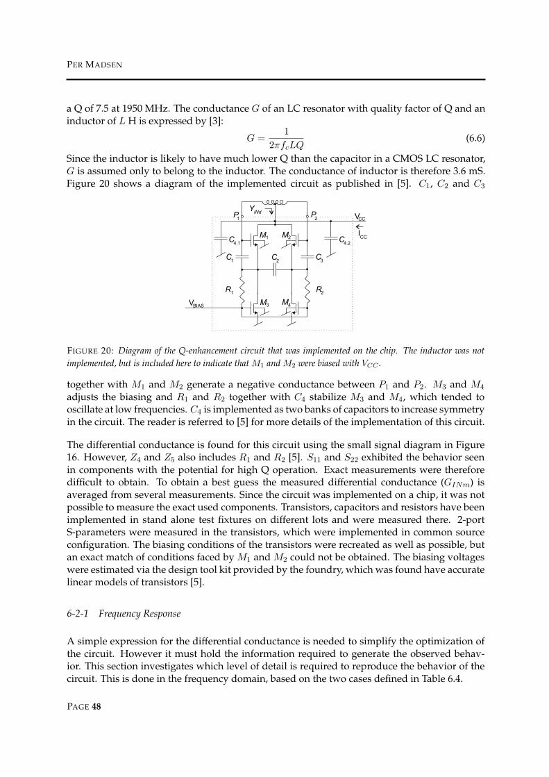
PER MADSEN
a Q of 7.5 at 1950 MHz. The conductance G of an LC resonator with quality factor of Q and aninductor of L H is expressed by [3]:
G =1
2πfcLQ(6.6)
Since the inductor is likely to have much lower Q than the capacitor in a CMOS LC resonator,G is assumed only to belong to the inductor. The conductance of inductor is therefore 3.6 mS.Figure 20 shows a diagram of the implemented circuit as published in [5]. C1, C2 and C3
FIGURE 20: Diagram of the Q-enhancement circuit that was implemented on the chip. The inductor was notimplemented, but is included here to indicate that M1 and M2 were biased with VCC .
together with M1 and M2 generate a negative conductance between P1 and P2. M3 and M4
adjusts the biasing and R1 and R2 together with C4 stabilize M3 and M4, which tended tooscillate at low frequencies. C4 is implemented as two banks of capacitors to increase symmetryin the circuit. The reader is referred to [5] for more details of the implementation of this circuit.
The differential conductance is found for this circuit using the small signal diagram in Figure16. However, Z4 and Z5 also includes R1 and R2 [5]. S11 and S22 exhibited the behavior seenin components with the potential for high Q operation. Exact measurements were thereforedifficult to obtain. To obtain a best guess the measured differential conductance (GINm) isaveraged from several measurements. Since the circuit was implemented on a chip, it was notpossible to measure the exact used components. Transistors, capacitors and resistors have beenimplemented in stand alone test fixtures on different lots and were measured there. 2-portS-parameters were measured in the transistors, which were implemented in common sourceconfiguration. The biasing conditions of the transistors were recreated as well as possible, butan exact match of conditions faced by M1 and M2 could not be obtained. The biasing voltageswere estimated via the design tool kit provided by the foundry, which was found have accuratelinear models of transistors [5].
6-2-1 Frequency Response
A simple expression for the differential conductance is needed to simplify the optimization ofthe circuit. However it must hold the information required to generate the observed behav-ior. This section investigates which level of detail is required to reproduce the behavior of thecircuit. This is done in the frequency domain, based on the two cases defined in Table 6.4.
PAGE 48

PhD Thesis R04-1026 , March 3, 2005.Texas Instruments Denmark A/S & RISC group, AaU
TABLE 6.4: Biasing conditions of the two test casesCase VBIAS [V] ICC [mA] Avg. Power consumption [mW]
a 0.6 8.3 20.8b 0.8 32.2 80.5
A biasing point close to case a is used in chapter 7, where the circuit is used in an LC resonator.Case b is where the differential conductance was smallest. GINm is shown in Figure 21 togetherwith estimates made with Eq. (6.1) (GINs) and Eq. (6.2) (GINc). The conductance of the capac-itors is important, while the reactance of y is small compared to the trans-conductance (gm).The capacitors are of different sizes [5]. This is expressed by replacing C2 with nC1. The con-ductance is represented by the potential Q and the same value is used for all capacitors. Thesimplified version of Eq. (6.1) is:
YINg(f) =1
2
2πfC1
(1
Q(f)+ j
) +1
n2πfC1
(1
Q(f)+ j
) +gm(f)
n
(2πfC1
(1
Q(f)+ j
))2
(6.7)
The differential conductance GINg(f) is the real part of YINg(f) as expressed by:
GINg(f) =n (2πfC1)
2
((gm(f) + 2πfC1
2n + 1Q(f)
)(1
Q(f)2− 1
)+ 4πfC1
2n + 1Q(f)
)
(gm(f) + 2πfC1
2n + 1Q(f)
)2
+ (2πfC1(2n + 1))2(6.8)
Eq. (6.7) is also included in Figure 21. C1 and C2 are estimated from measurements, averagedfrom 1 to 3 GHz. Eq. (6.7) use the same Q for both C1 and C2. The potential Q of the capacitorschanged significantly over frequency. In Eq. 6.8 the used Q is the averaged of C1 and C2,calculated for each measured frequency.
Figure 21 shows that although Eq. (6.1) estimates larger magnitudes of differential conductancethan Eq. (6.2), the relative error is not as large as in the experiments with BJT transistors. It isalso seen that Eq. (6.7) estimates the notch at approximately the same frequency as Eq. (6.2). Theimportant information is therefore maintained. The smallest differential conductance achievedat 1950 MHz is approx -2.8 mS. This is sufficient to enhance the Q of the intended inductor to34.
6-2-2 Choice of Trans-Conductance
The experiment with BJTs showed that increasing the biasing voltage did not always increasethe gm in the transistors. This section investigates if the same effects are present in the CMOSimplementation. To this end VBias was increased form 0 to 1.1 V in steps of 0.1 V. ICC keptincreasing during this sweep. 2-port S-parameters were measured at each biasing point. Thedifferential conductance is calculated from these measurements and estimated from the mea-surements on the transistors. The results are shown in Figure 22 for 500 MHz (A) and 1950 MHz
PAGE 49

PER MADSEN
0 1 2 3−4.5
−4
−3.5
−3
−2.5
−2
−1.5
−1
−0.5
0
0.5Case a
Frequency [GHz]
Diff
eren
tial c
ondu
ctan
ce [m
S]
: GINm
: GINc
: GINs
: GINg
0 1 2 3−4.5
−4
−3.5
−3
−2.5
−2
−1.5
−1
−0.5
0
0.5Case b
Frequency [GHz]
: GINm
: GINc
: GINs
: GINg
FIGURE 21: Differential conductance versus frequency. Case a and b refer to Table 6.4. GINm is estimated frommeasurements, GINs is estimated from Eq. (6.1), GINc from Eq. (6.2) and GINg from Eq. (6.7).
(B). The first point of GINm is measured with all supplies off, resulting in a gm equal to zero.The next point is measured with only the supply voltage on, but because of R1 and R2, the cir-cuit is active and M1 and M2 presents a gm of approx 10 mS. The remaining 7 measured pointsrepresent VBIAS from 0.5 to 1.1 V in steps of 0.1 V. For some frequency fs the optimum value ofgm gm_opt_fs is found through an analysis of extremes in Eq. (6.8):
gm_opt_fs = ±2πfsC11 + Q(fs)2 + 2a + 2aQ(fs)2
(1 + Q(fs))Q(fs)(6.9)
For Eq. (6.9) to apply Eq. (6.8) must be a good estimate of the differential conductance in theproximity of the notch. This is the case at 500 MHz, where the optimal conductance is estimatedto 26 mS. The maximal achievable differential conductance is estimated from both Eq. (6.7) andEq. (6.2). The results are marked by "x" and "∗" respectively in Figure 22. At 1950 MHz gm_opt_fs
is estimated to 103 mS, which is beyond the 46 mS achievable with the transistors. This pointis therefore not included in Figure 22.
It is seen that Eq. (6.8) is close to Eq. (6.2) until gm no longer increases with the biasing volt-age. At 500 MHz the largest magnitude of differential conductance is obtained where gm is26 mS. This is close to the point estimated by Eq. (6.9). No measurements were made withthe biasing that generated gm_opt_fs. The differential conductance estimated with gm_opt_fs cantherefore not be expected to appear exactly on the traces for GINc and GINg. At 1950 MHz thelargest magnitude of differential conductance is obtained where the magnitude of the trans-admittance is 45 mS. At this point gm stabilizes even though VBIAS is increased further. HereGINm and GINc starts to decrease while GINg stabilizes. This indicates that the parasitics in-
PAGE 50

PhD Thesis R04-1026 , March 3, 2005.Texas Instruments Denmark A/S & RISC group, AaU
0 10 20 30 40 50
−4
−3
−2
−1
0
A
B
Trans−conductance (gm
) [mS]
Diff
eren
tial c
ondu
ctan
ce [m
S]
: GINm
: GINc
: GINg
FIGURE 22: Differential admittance versus the gm at A: 500 and B: 1950 MHz. GINm is estimated from measuredS-parameters, GINg is estimated from Eq. (6.7) and GINc from Eq. (6.2). "∗" marks the conductance estimatedwith gm_opt_fs in Eq. (6.2) and "x" marks the conductance estimated with gm_opt_fs in Eq. (6.7). Notice that "∗"and "x" are lying almost on top of one another.
cluded in Z4 and Z5 become more significant as the biasing voltage increases. Eq (6.8) doesnot include Z4 and Z5 and can thus not take this effect into account. The fact that an optimalchoice for gm is found in Eq (6.8) shows that increasing gm alone will not always increase themagnitude of differential conductance.
6-2-3 Choice of Capacitance
Section 6-2-2 shows that an optimum exists for gm on given frequency. This section investigatesif an optimum exists for capacitance. Knowledge of the best choice of capacitance may help thedesigner to optimize the negative conductance of the circuit, if gm for one reason or another,can not be changed. It is assumed that all the used capacitors have the same Q. This can beachieved if the capacitors are implemented as parallel connections of the same unit capacitor.The best choice of C1, C1_opt, is found through analysis of extremes in Eq. (6.8):
C1_opt =gmQ
6πf(2n + 1)
(A− 4Q2 + 1
− 3Q2 − 1(Q2 + 1)A
)(6.10)
where
A = 3
√√√√27Q4 + 18Q2 − 1 + 3
√327Q4 + 10Q2 − 1
Q2 + 1(Q2 + 1)Q (6.11)
Figure 23 shows estimates and simulations of differential conductance as a function of capac-itance at 1950 MHz. The test is conducted with a Q of 71 to get a value close the what hasbeen measured on the capacitors. In order to provide measured data for this sweep, one circuitwould have to be implemented for each measurement point. Instead capacitors are swept us-ing the design kit provided by the foundry, as this was found to simulate the transistors well[5]. simulated values for differential conductance are denoted GINsim. Finally GINc and GINg
are calculated with the estimated C1_opt. These are marked by "∗" and "x" respectively and theone measured data point available for each bias point is marked by "·".
PAGE 51

PER MADSEN
2 4 6 8 10
−4
−3
−2
a
b
Capacitance [pF]
Diff
eren
tial c
ondu
ctan
ce [m
S]
: GINsim
: GINc
: GINg
FIGURE 23: Differential conductance as function of capacitance at 1950 MHz. a and b refer to the cases defined inTable 6.4. n is assumed to be 1. GINc is estimated from Eq. (6.2) and GINg estimated from Eq. (6.7), differentialconductance estimated for C1_opt using Eqs. (6.2) and (6.7), are marked with "∗" and "x" respectively. The onlyavailable measured data is marked by "·".
The estimates of C1_opt fits Eq. (6.2) well, but they are 0.5 - 1 pF larger than indicated by thesimulations. The differential conductance changes slowly near the notch, so the resulting dif-ference in the differential conductance is not significant. It may therefore be desirable to choosecapacitances smaller than the optimal choice in order to save space and reduce the capacitiveimpedance of the Q-enhancement circuit.
6-3 Conclusion
This chapter investigates two implementations of a proposed Q-enhancement circuit. Bothwere found to have notches in the frequency domain, but the notches were caused by differ-ent factors. In the BJT experiment the reactive part of the transistors trans-admittance was thesignificant factor, while the conductance of the used capacitors was the significant factor in theCMOS implementation. In both cases the optimal choice of capacitance was estimated fromsimplified expressions and in both cases it was found that infinitely low differential conduc-tance can not be obtained only by increasing the capacitance. The existence of an extreme inEq. (6.8) shows that the same is the case for gm in the CMOS implementation. Both experimentsalso showed that at some point, increasing the biasing voltage and hence DC current no longerincreases the trans-admittance in the transistors. If this point is reached, the only option is toincrease the size of the transistors, as done in the experiment with BJTs, but the extreme pointfound in Eq. (6.8) shows that even this has a limit in the CMOS implementation.
The scientific contributions provided through this part of the project are:
• Demonstration that the suggested differential circuit indeed can generate a negative dif-ferential conductance, both when implemented with discrete components and on a stan-dard CMOS process.
• An analytical expression that describes the differential conductance of the circuit andincludes transistor output impedances.
PAGE 52

PhD Thesis R04-1026 , March 3, 2005.Texas Instruments Denmark A/S & RISC group, AaU
• Demonstration that the performance can be optimized through the right combination ofcapacitance and trans-admittance.
The Q-enhancement circuit was proposed because of its assumed potential for high linearity orlow noise [2]. However this assumption was based of an analysis that did not include the tran-sistors output impedances. This work has demonstrated that the transistor output impedancesare significant for linear operation. These parasitics should therefore be included in analysis ofnoise and linearity.
REFERENCES
[1] D.Li and Y. Tsividis. Active LC filters on silicon. In IEE Proceeding of Circuits Devices Systems I, volume 147,pages 49 – 56, February 2000.
[2] Risto Kaunisto. Monolithic Active Resonator Filters for High Frequencies. PhD thesis, Helsinki University ofTechnology, 2000.
[3] Herbert L. Krauss, Charles W. Bostian, and Frederick H. Raab. Solid State Radio Engineering. ISBN 0-471-03018-X. John Wiley & Sons, 1980.
[4] P. Madsen, T. Larsen, J. H. Mikkelsen, and J. C. Lindof. On the design of a differential common collectornegative resistance. In Proceedings of the 21st Norchip Conference, pages 100 – 103, Riga, Latvia, November 2003.Norchip, IEEE.
[5] P. Madsen, T. Larsen, J. H. Mikkelsen, and J. C. Lindof. An RF CMOS differential negative resistance for Q-enhancement. In Proceedings of the 7th International Conference on Solid State and Integrated Circuit Technology,pages 1256 – 1259, Beijing, October 2004. ICSICT.
[6] Per Madsen. Simulating overall performance requirements for transmitters in IMT 2000 FDD user equipment.In Proceedings of the European Conference on Wireless Technology, Wireless Technologies 2001, pages 47 – 50, Lon-don, September 2001. European Microwave Week.
[7] T. Soorapanth and S. S. Wong. A 0 dB-IL, 2140±30 MHz bandpass filter utilizing Q-enhanced spiral inductorsin standard CMOS. Journal of Solid State Circuits, 37(5):579 – 586, May 2002.
[8] Infineon Tehcnologies. BC847S npn silicon af transistor array. internet, 2003.[9] Infineon Tehcnologies. BFP405 npn silicon rf transistor. www.infineon.com, 2005.
[10] Infineon Tehcnologies. BFP540F npn silicon rf transistor. www.infineon.com, 2005.[11] Infineon Tehcnologies. BFP640F npn silicon germanium rf transistor. www.infineon.com, 2005.[12] Infineon Tehcnologies. BFP650 npn silicon germanium rf transistor. www.infineon.com, 2005.
PAGE 53


PhD Thesis R04-1026 , March 3, 2005.Texas Instruments Denmark A/S & RISC group, AaU
7 Q-ENHANCED RESONATOR
This chapter presents results obtained with an experimental implementation of a Q-enhancedmonolithic LC resonator, using the Q-enhancement circuit described in Chapter 6. Althoughthe literature holds may examples of monolithic resonators, none uses the Q-enhancement cir-cuit presented here. The experiment reveals weaknesses and forces of this used Q-enhancementcircuit. The resonator was designed to have a mid range center frequency (fC) of 1950 MHz anda tuning range of approx 100 MHz using the design kit available form the foundry. Howeverthis was not obtained in the measurements. The simulated capacitors were 10 % smaller thanmeasurements indicated. Further more errors of 100 % in the simulation of the capacitance intransistors in weak accumulation mode meant that the simulated tuning range was 10 MHzlarger than measured. Although such errors might be expected, they are too large to for anefficient design of high Q resonators. In the following measured data are therefore used forthese components in the simulations.
Figure 24 shows a diagram of the implemented circuit. The LC resonator consists of transistorsM1 through M10 with de-coupling capacitors C1 through C10 and the inductor L1. The Q-enhancement circuit consists of transistors M11 through M14, capacitors C11 through C14 andthe resistors R1 and R2. Refer to [4, 5] for more details on this circuit.
FIGURE 24: Diagram of the implemented Q-enhanced LC resonator.
PAGE 55

PER MADSEN
7-1 Results
The inductor was measured to 5.6 nH and had a potential Q of about 7.5 [5] at 1850 MHz.From Eq. (6.6) the conductance of the inductor is found to be approximately 2 mS at this fre-quency. The varactors have a high potential Q and their conductance is thus insignificant. TheQ-enhancement circuit is capable of compensating for up to 2.8 mS, so in this case it may bebacked off. Compensation is achieved with a bias voltage of 0.58 V and a current consumptionof 6.9 mA from a 2.5 V supply. The circuit therefore consumed 17.3 mW in this configura-tion. Figure 25 shows simulated and measured differential conductance and reactance on afrequency in the middle of the resonators tuning range. The reactance is zero at the center fre-quency of LC resonators [3]. The center frequency is thus approx. 1820 MHz. At this point theconductance was approx. 0.2 mS so the Q of the resonator was about 80. However, Q of thismagnitude are difficult to measure in a 50 Ω system.
1.75 1.8 1.85 1.9
0
0.1
0.2
0.3
0.4
Frequency [GHz]
Gt [m
S]
: Meas.: Sim.
1.75 1.8 1.85 1.9−2
−1
0
1
2
Frequency [GHz]
Imag
(Y(2
π f)
) [m
S] : Meas.
: Sim.
FIGURE 25: Differential conductance and reactance when the resonator is operated at mid range. Dots are mea-sured results and lines are simulated.
Simulated and measured frequency range and Q are listed in Table 7.1. The frequency step sizeis between 2 and 4 MHz depending on whether it is measured in the upper or lower frequencyranges.
PAGE 56

PhD Thesis R04-1026 , March 3, 2005.Texas Instruments Denmark A/S & RISC group, AaU
TABLE 7.1: Simulated (sim.) and measured (meas.) corner and mid values for fC and resulting Q factor.fCc sim. [MHz] Qsim. fC meas. [MHz] Qmeas.
1776 87 1779 531825 153 1822 781872 298 1870 122
7-2 Discussion
The circuit is more than capable of compensating for the inductor used in the experiment, butfC is not as expected. This is mainly because the implemented (MIM) capacitors were largerthan the design kit estimated. The resonator is sensitive to tolerances on both capacitors and gm
in the transistors. Tolerances on gm mainly influence the Q, while the capacitors influence boththe Q and fC . Automated tuning schemes such as voltage controlled filter tuning and voltagecontrolled oscillator tuning exists [1]. Such schemes may control both frequency and Q, butthe required tuning range must be available in the resonator. The simulations presented herewere conducted using data measured on stand alone implementations of the capacitors C11 andC12. C11 was implemented on one lot and C12 on another. Although the statistical backgroundis limited, the experiment indicated some repeatability in the MIM capacitors. Even thoughthe measurements of the LC resonator were conducted on a 3rd lot, the data measured on thecapacitors still provided a good match when used in the simulations. Simulations of weakaccumulation mode of the FETs used in the varactor bank were also inaccurate, but fC wasmore sensitive to errors on the capacitors than this error.
The use of measured data in the simulations provided a good estimate of fC , but tolerancesare not known. If the design was to be made for the tolerances in the design kit, the frequencytuning range of the resonator would have to be increased. This requires that a larger varactorbank is implemented, but since the varactors are capacitive in weak accumulation mode, this isnot possible in the present configuration. The problem with the design is that the size of C11 toC13 and L1 sets limits to how large a capacitance may be added in the varactor bank. However,there are several ways to remedy this:
• The center frequency f0 of an LC resonator is [3]:
f0 =1
2π√
LC(7.1)
By reducing the size of the inductor, the size of the capacitance may be increased. Thismeans that the varactor bank may generate a larger percentage of capacitance, but onthe other hand, it would also require a larger shift in capacitance to change f0. The con-ductance in the LC resonator is inverse proportional with the used inductance as seen inEq. (6.6). This means that the Q-enhancement circuit would have to provide a smaller dif-ferential conductance to compensate for the same Q and this in turn means higher currentconsumption.
• Figure 23 indicates that the Q-enhancement circuit can provide a differential conductance
PAGE 57

PER MADSEN
of -2 mS with capacitors of 1 pF, when the transistors are biased for maximal gm. Thisreduces the capacitance significantly, but it will also increase the current consumption.
• If the capacitors and transistors were ideal, the imaginary part of Eq. (6.1) would onlybe a series connection of C11, C12 and C13. In this case the overall admittance could bereduce by making one of these capacitors smaller and compensate for the lack of Q byincreasing the others. The transistors are not ideal, but the capacitors are dominant so asimilar effect is expected. However, this will also change the performance with respect tonoise and linearity [2].
• The circuit could be scaled both in capacitance and transistor size. In this manner a moreefficient operating point may be found for the transistors and smaller capacitors may beapplied. However, this approach may also change the performance with respect to noiseand linearity.
7-3 Conclusion
The Q-enhancement circuit has been used in a monolithic LC resonator. The circuit was morethan capable of compensating for the losses in the used inductor, but this is not surprising asthe circuit was not designed for that particular inductor. The LC resonator proved to be sensi-tive to tolerances particularly on the capacitors used in the Q-enhancement circuit. This meansthat a large tuning range is required to compensate for tolerances or poor models of the capac-itors. The use of capacitors means that the circuit exhibits a significant capacitive differentialimpedance. This limits the size of the varactor bank and thus the frequency tuning range. Analternative is to use measured data in the simulations as demonstrated in this chapter. Thisapproach has estimated the center frequency at 1850 MHz with an error of only 3 MHz, whichis sufficient to make an efficient design, but it requires that the components have been imple-mented in stand alone fixtures before the design is made. It is always important not to applymore capacitance than necessary. The author believes that the analysis of optimization of thecircuit presented in Chapter 6 may help the designer to make he best choice of capacitance.
REFERENCES
[1] D.Li and Y. Tsividis. Active LC filters on silicon. In IEE Proceeding of Circuits Devices Systems I, volume 147,pages 49 – 56, February 2000.
[2] Risto Kaunisto. Monolithic Active Resonator Filters for High Frequencies. PhD thesis, Helsinki University of Tech-nology, 2000.
[3] Herbert L. Krauss, Charles W. Bostian, and Frederick H. Raab. Solid State Radio Engineering. ISBN 0-471-03018-X.John Wiley & Sons, 1980.
[4] P. Madsen, T. Larsen, J. H. Mikkelsen, and J. C. Lindof. An RF CMOS differential negative resistance for Q-enhancement. In Proceedings of the 7th International Conference on Solid State and Integrated Circuit Technology,pages 1256 – 1259, Beijing, October 2004. ICSICT.
[5] P. Madsen, T. Larsen, J. H. Mikkelsen, and J. C. Lindof. An RF CMOS Q-enhanced LC resonator. Oslo, November2004. Accepted for: Norchip 2004.
PAGE 58
PhD Thesis R04-1026 , March 3, 2005.Texas Instruments Denmark A/S & RISC group, AaU
8 CONCLUSION
This conclusion first recollects the important results obtained during the Ph.D. project. Then theprojects significant scientific contributions are listed and finally the author assesses which tasksremain, before the best approach to implement UMTS transmitters on CMOS can be identified.
8-1 Important Results
This section recollects the important results obtained during the project.
• At the time of writing, the direct up-conversion transmitter appears to be the best archi-tecture for integration on CMOS.
• The UMTS receiver sets the most harsh requirement to the transmitter output spectrum.An RF bandpass filter must be inserted before the power amplifier to meet this require-ment.
• The RF bandpass filter must provide 3 dB gain in the uplink band and 12 dB attenuationat frequencies 70 MHz below the uplink band. This must be achieved without addingsignificantly to output noise and ACLR.
• Two approaches to obtain the required attenuation are identified. Both can be imple-mented with resonators with a quality factor of about 46 and 6 MHz precession of thecenter frequency. The designer may chose between deploying two such resonators, withenough tuning range to compensate for tolerances, or one resonator with a tuning rangeat least 60 MHz wider than this.
• If noise and linearity are important factors, Q-enhancement is the best solution to imple-ment resonators with high quality factors on CMOS.
• A Q-enhancement circuit is implemented on CMOS. It generates a differential conduc-tance of -2.8 mS at 1950 MHz with a power consumption of 80 mW.
• An LC resonator with the Q-enhancement circuit described above is implemented onCMOS. The center frequency of the resonator can be tuned from 1780 MHz to 1870 MHzin steps down to 2 MHz. The Q-enhancement circuit improved the quality factor from 7.5to beyond 50 with a power consumption of 17 mW. The center frequency was simulatedwith a precision of approximately 3 MHz.
The frequency range and quality factor required in the RF filter could be obtained. It is thereforeassumed that the filtering required in the direct up-conversion transmitter for UMTS can beobtained on CMOS.
8-2 Scientific Contributions
The project has generated the following scientific contributions:
PAGE 59

PER MADSEN
• An experimental analysis of how selected circuit imperfections affect EVM and ACLR inuplink signals for UMTS.
• Analytical expressions that relate EVM to amplitude and phase imbalance in the I and Qbranches. The expressions take into account the phase and amplitude adjustments con-ducted during calculation of EVM.
• An analysis of requirements to functional blocks in direct up-conversion transmitters forUMTS user equipment.
• Demonstration that a differential circuit, based on BJTs in common collector configurationand capacitors, can generate negative differential conductance.
• An analytical expression for the differential admittance of the Q-enhancement circuitmentioned above, that takes the output impedances of the transistors into account.
• Demonstration that the Q-enhancement circuit also works on CMOS and that the analyt-ical expression also improves estimates when applied to CMOS circuits.
• Demonstration that the Q-enhancement circuit does enhance the quality factor of an LCresonator.
• Demonstration that the center frequency of an LC resonator with a high quality factor canbe simulated with great precision, using data measured on stand alone implementationsof the used passive components.
The project has therefore made scientific contributions to the understanding of the UMTS sys-tems and the design of Q-enhancement circuits for RF operation on a standard CMOS process.
8-3 Future Work and Research
Many questions concerning the implementation of transmitters for UMTS on a standard CMOSprocess have been answered during this project. However, many more questions need to beanswered before the most efficient approach can be identified. This applies both to the archi-tecture studies and design of Q-enhanced LC resonators.
The polar modulator was mentioned as a potential competitor to the direct conversion trans-mitter. This architecture is not mature so it will take some efforts before it is documented aswell as the case is for the direct up-conversion transmitter at the time of writing. In the meantime the direct conversion transmitter appears to be the best choice. However, there is alsowork to be done on integration of filters on CMOS before the direct up-conversion transmit-ter can be integrated. An LC resonator with a center frequencies in the UMTS uplink bandremains to be implemented. It is possible to simulate the frequency range to within 3 MHz ofmeasurements and from the knowledge obtained on the design of the Q-enhancement circuit,the author thinks that an LC resonator with the desired center frequency can be designed. TheQ-enhancement circuit was chosen for its potential noise and linearity performance. However,an analysis of noise and linearity that includes the transistor output impedances must be con-ducted for both this circuit and competing circuits in order to determine which one would bethe best choice for the intended application.
PAGE 60

PhD Thesis R04-1026, March 3, 2005.Texas Instruments Denmark A/S & RISC group AaU
RF Requirements for UTRA/FDD Transceivers
P. Madsen, O. K. Jensen, T. Amtoft, R. V. Reynisson, J. H. Mikkelsen, S. Laursen, C. R. Iversen,T. E. Kolding, T. Larsen and M. B. Jenner
The 4th International Symposium on Wireless Personal Multimedia Communication (WPMC)Aalborg, Denmark, pp. 197 - 202, September 2001.
PAGE 61


RF Requirements for UTRA/FDD Transceivers
Per Madsen∗∗, Ole K. Jensen∗, Torben Amtoft∗∗, Ragnar V. Reynisson∗,Jan H. Mikkelsen∗, Søren Laursen∗, Christian R. Iversen∗,Troels E. Kolding∗, Torben Larsen∗, Michael B. Jenner∗
∗∗Telital R&D Denmark,∗RISC Group Denmark, CPK, Aalborg University
[email protected], http://tele.auc.dk/risc
AbstractUnified RF requirements are derived for an UTRA/FDD com-pliant mobile transceiver. Consideration of system issues,multi-mode operation, and interfacing concerns leads to de-tailed receiver and transmitter calculations based on exist-ing UMTS specifications. Finally, compliant and design-compatible transceiver requirements are derived.
KeywordsRF Transceiver, UTRA/FDD, transceiver requirements, directup/down conversion.
1. IntroductionThe UTRA/FDD mobile standard provides an improved plat-form for personal communications including voice, data, andmultimedia services compared to current 2G systems. In or-der for UTRA/FDD to retain a competitive advantage, high-performance and low-costuser equipment(UE) must bemade available to the general public. In this work, unifiedUTRA/FDD UE transceiver requirements are derived on blocklevel, based on previous work for the receiver branch [1] andongoing work for the transmitter branch [2].
2. Duplex AspectsAs UTRA/FDD is based onfrequency division duplex(FDD),the required isolation betweentransmitter (Tx) and receiver(Rx) can only be provided by means of a duplex filter. Theperformance of the duplex filter is very important for thetransceiver requirements and since the available physical sizeis limited, several design compromises apply:
• A low insertion loss in the Tx-band is difficult to com-bine with a high Tx-Rx isolation in the Rx-band.
• A low insertion loss in the Rx-band is difficult to com-bine with a high Tx-Rx isolation in the Tx-band.
The transmitter-induced noise level at the receiver input (Rx-band) is determined by the transmitter noise level and the du-plexer isolation. A level of -111 dBm/3.84 MHz is shown inlater sections to give an acceptable degradation of receiver sen-sitivity. To reduce insertion loss at Tx, the duplex filter shouldonly attenuate noise generated by thepower amplifier(PA) it-self, while noise generated before the PA is filtered inside theTx-chain. Assuming (i) a class 3 transmitter with a maximumoutput power of 24 dBm and (ii) a Tx-insertion loss of 2 dB, du-plexer isolation of 37 dB is needed. Also, it need to be consid-ered that a Tx-leakage signal may disturb the Rx-band because
of receiver nonlinearities. With 50 dB of Tx-Rx isolation, theleakage level from a class 3 transmitter becomes -24 dBm whichis realistic in combination with a 3 dB Rx-insertion loss. Theassumed duplexer performance data is summarized in Table 1.
Parameter RequirementTx-Ant attenuation (Tx-band) [dB] < 2Rx-Ant attenuation (Rx-band) [dB ] < 3Tx-Rx isolation (Rx-band) [dB] > 37Tx-Rx isolation (Tx-band) [dB] > 50
Table 1: Duplex filter requirements.
3. Receiver
To ensure that the receiver has adequate performance it mustmeet requirements for a number of tests defined in theUTRA/FDD standard [3]. For each of these tests, a BER of10−3 must be achieved at a user bit rate of 12.2 kbps. To meetthis, a(Eb/Nt)eff of 5.2 dB is needed [4]. A margin of 0.8 dBis suggested [4] to cover for baseband implementation imper-fections. It is therefore decided to use 6 dB as the target valuefor (Eb/Nt)eff. It is assumed that any disturbing signals, suchas distortion products, may be treated as noise. This allowsthermal noise and any distortion products to be combined in asinglepower spectral density(PSD),Nt. It is further assumedthat any signal that is not on the desired channel is removed byfiltering in the digital baseband part. In order not to overloadthe ADCs, such signals are attenuated to the power level of thedesired signal before sampling takes place. Several disturbancemechanisms are active so a disturbance power budget must bechosen. Further, it should be noted that all Rx calculations re-late to the Rx chain following the switch/duplexer arrangement,unless otherwise specified. This implies that power levels spec-ified in the standard are adjusted for the loss in the duplexer.As an example, during sensitivity testing, a wanted signal of-117 dBm is specified. This value is adjusted to -120 dBm dur-ing calculations to take the estimated duplexer loss of 3 dB intoaccount.
3.1. Noise Figure
The sensitivity requirement is specified for a data channel(DPCH) signal power,Si. Based on the required(Eb/Nt)eff theacceptable noise and distortion power in a channel bandwidth,

Pacc, is calculated as
Pacc = Si − (Eb/Nt)eff + 10 · log(PG)
= −120− 6 + 25 = −101 dBm, (1)
where the processing gain,PG, is given as chip rate over bitrate. The chip and bit rates equals 3.84 Ms/s and 12.2 kbps,respectively. The actual bit rate that should be used is 15 kbpsas this is the bit rate prior to the encoding. However, some de-gree of coding gain is expected and for that matter 12.2 kbpsis used. The Tx-leakage signal with varying envelope results indistortion products located at baseband due to even-order non-linearities in the receiver. As a result,Pacc consists of Rx-noise,PRx,N , Tx-noise,PTx,N , and distortion products due to Tx-leakage and Rx-nonlinearities. In the special case where theTx-signal is turned off,PRx,N = Pacc resulting in a Rx noisefigure of 7 dB. To make room for any Tx-signal noise and distor-tion effects, the Rx noise figure must be reduced. As a compro-mise, a 1 dB reduction (PRx,N = Pacc - 1 dB) is accepted. Al-lowing the remaining noise and disturbance power to be sharedequally betweenPTx,N andPTx,D, they must display distur-bance powers less than -111 dBm/3.84 MHz. This disturbancebudget leads to the power levels illustrated in Figure 1.
Figure 1: Illustration of the noise and disturbance power distri-bution.
In other tests, the Tx-power is reduced to 20 dBm for a powerclass 3 transmitter. This only gives a minor reduction in Tx-noise and is therefore neglected in the following calculations.
3.2. Second-Order Intercept Point
The presence of strong modulated signals with varying envelopeis critical in baseband circuits since some even-order distortionproducts end up at baseband. To establish requirements to re-ceiver linearity, the illustration on Figure 2 is useful. Figure 2shows how to find the input-referred nonlinear response for anN th order system with a given intercept point. Based on the re-lations given in Figure 2, the required Nth order intercept pointis given as
iIPN =N
N − 1· iPINT − 1
N − 1· iPDIS [dBm], (2)
where N is the order of the nonlinearity,iPINT the input-referred power of the interferer, andiPDIS the acceptable dis-tortion level referred to the input. To use Eq. (2), the specifictest scenario must be considered. During the in-band modulatedblocker test, the wanted signal is at -114 dBm, which is 3 dBabove the sensitivity limit. This results in aPacc of -98 dBm.Referred to the output of the duplexer, the blocking levels are at-59 dBm, at an offset of±10 MHz, or at -47 dBm, at an offsetof ±15 MHz. The test scenario is shown in Figure 3. A distur-bance budget allowing for 50% (-3 dB) receiver noise and Tx-disturbance and for 50% (-3 dB) noise from the second-orderproduct is chosen. Based on Eq. (1) and the disturbance bud-get, both the maximum allowed noise power and second-order
Figure 2: Geometrical interpretation of intercept point.
disturbance is -101 dBm. A significant part of the power ofthe second-order products is at baseband. However, high-passfiltering can be used to reduce this without significant signaldegradation [5]. Further, as the spectra of the second-order dis-tortion products are wider than the wanted signal spectrum, low-pass filtering also gives an improvement. In all, the combinedreduction of second-order products is estimated to 6 dB. Usingthis, the second-order intercept point caused by the blocker at±10 MHz is found from Eq. (2) as
iIP2 = 2 · (−59)− (−101 + 6) = −23 dBm (3)
Using the same calculations the intercept point caused by theblocker at±15 MHz is found to 1 dBm.
Figure 3: In-band modulated blocker test. (a) RF spectrum withwanted signal an offset modulated blocker. (b) Baseband spec-trum with desired and disturbing signals.
During the sensivity test, the Tx-leakage signal acts as a mod-ulated blocker. Second-order distortion is therefore a severeproblem. The required second-order intercept point is foundto
iIP2 = 2 · (26− 50)− (−111 + 6) = 57 dBm, (4)
where 50 dB of Tx-Rx isolation is included. While this appearsto be a very hard target value, it is by no means unrealistic. Oneapproach could be to make use of a RF filter after the first LNAstage.

3.3. Third-Order Intercept Points
The in-band third-order intercept point is determined from theintermodulation test. The wanted signal is 3 dB above the sen-sitivity limit, corresponding to -117 dBm while the interferingsignal scenario consists of a CW-signal at an offset of±10 MHzand a modulated signal at an offset of±20 MHz. Both interfer-ing signals are at a power level of -49 dBm as Figure 4 shows.
Figure 4: Intermodulation test.
A noise budget is set up as follows: Noise power: 50% (-3 dB),third-order IM-product: 50% (-3 dB). Combined, the distur-bances must not exceed -98 dBm. Based on this disturbancebudget, it is possible to calculate the required third-order inter-cept point from Eq. (2)
iIP3 =3
2· (−49)− 1
2· (−101) = −23 dBm (5)
Because of Tx-leakage, the blocking tests described in [1] alsosets demands toiIP3. The out-of-band blocking test specifiesthat a CW-blocker is present with a level of -44/-30/-15 dBmat minimum distances from the Rx-band of 15/60/85 MHz, re-spectively, while the Tx output power is 20 dBm. Blockers atoffsets of 85 MHz may generate intermodulation products. Inthis test the third-order IM-products is allowed generate 50 %of the interfering power. If the frequency of the CW-blockeris abovethat of Tx-leakage signal and the duplex filter offers27 dB attenuation at offsets of 85 MHz from the Rx-band, therequirediIP3 is found by [1]
iIP3 =1
2·(−28 + 2 · (−42))− 1
2·(−101) = −5.5 dBm (6)
The requirement toiIP3 is more harsh if the frequency of theCW-blocker isbelow that of the Tx-leakage signal. It is as-sumed that Eq. (6) still applies in this case. To obtain aniIP3
of -5 dBm, 40 dB attenuation of the CW-blocker is required inthe duplex filter.
3.4. In-band Selectivity
The selectivity demands are made from the philosophy that dis-turbing signals should be attenuated to the level of the desiredsignal in order not to overload the ADCs. A special test is set upfor the selectivity for the first adjacent channel located at an off-set of±5 MHz. Here, all signals are well above the noise leveland no other disturbance mechanisms are active. The resultingselectivity requirement at±5 MHz offset is 33 dB [1]. Selec-tivity here includes any kind of filtering and frequency sensi-tivity of the demodulator. Several tests use interfering signals
at offsets of±10 MHz. The harshest requirement to selectiv-ity is made by the third-order IM test in which an interferer at-49 dBm is feed to the receiver. The requirement here is 49 dBattenuation. For the remaining Rx-band the blocking test makesa requirement of 51 dB attenuation. 85 MHz below the Rx-band the blocking test makes a requirement of 56 dB attenua-tion. Finally the sensitivity test makes a requirement of 77 dBattenuation in the Tx-band.
4. TransmitterTransmitter requirements for the direct up-conversion architec-ture, illustrated in Figure 5, are derived from the transmittertests prescribed in the UTRA/FDD standard [3].
DAC
da
QUCd
a
LO
VGA FI PA
to duplexfilter
90o
DAC
Figure 5: Block diagram of transmitter.
4.1. Input/Output Signals
The input signals are delivered by two DACs, each assumed todeliver an RMS power of -13 dBm. Each DAC is assumed todeliver a signal with the PSD illustrated in Figure 6.
Figure 6: Power spectral density of the DAC.
The assumed PSD is such that no additional filtering of the DACoutput is required. In the overallRMS error vector magnitude(EVM) budget for the transmitter, the DACs are allowed to con-tribute with 8 % due to filtering and I/Q imbalance. The out-put signal specification is based on the noise requirements pre-sented in [3] and on the requirement to noise in the UTRA/FDDRx-band, taking the duplex filter attenuation into account. Theinput and output signals for the Tx front-end are specified inTable 2. Three bands have been identified as critical for thespurious emission tests. These bands are band 1 = [1805 MHz– 1880 MHz], band 2 = [1893.5 MHz – 1919.6 MHz], and band3 = [2110 MHz – 2170 MHz].
4.2. Spurious Requirements
Apart from the input signal spurious power, sources of unde-sired power are noise generated in the transmitter circuits andphase noise in the LO signal. The output noise is thus a sumof power contributions of each of these factors. In bands 1 to 3,the LO phase noise spectrum is assumed to be flat, meaning that
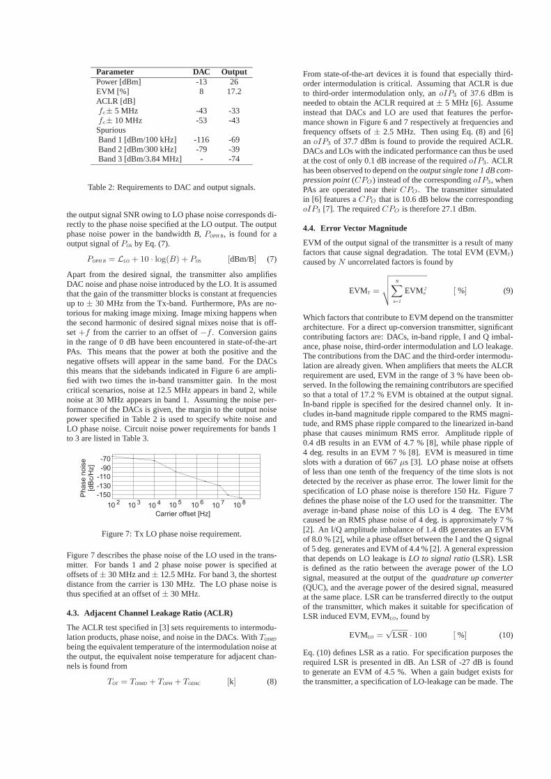
Parameter DAC OutputPower [dBm] -13 26EVM [%] 8 17.2ACLR [dB]fc± 5 MHz -43 -33fc± 10 MHz -53 -43SpuriousBand 1 [dBm/100 kHz] -116 -69Band 2 [dBm/300 kHz] -79 -39Band 3 [dBm/3.84 MHz] - -74
Table 2: Requirements to DAC and output signals.
the output signal SNR owing to LO phase noise corresponds di-rectly to the phase noise specified at the LO output. The outputphase noise power in the bandwidthB, POPH B, is found for aoutput signal ofPOS by Eq. (7).
POPH B = LLO + 10 · log(B) + POS [dBm/B] (7)
Apart from the desired signal, the transmitter also amplifiesDAC noise and phase noise introduced by the LO. It is assumedthat the gain of the transmitter blocks is constant at frequenciesup to± 30 MHz from the Tx-band. Furthermore, PAs are no-torious for making image mixing. Image mixing happens whenthe second harmonic of desired signal mixes noise that is off-set+f from the carrier to an offset of−f . Conversion gainsin the range of 0 dB have been encountered in state-of-the-artPAs. This means that the power at both the positive and thenegative offsets will appear in the same band. For the DACsthis means that the sidebands indicated in Figure 6 are ampli-fied with two times the in-band transmitter gain. In the mostcritical scenarios, noise at 12.5 MHz appears in band 2, whilenoise at 30 MHz appears in band 1. Assuming the noise per-formance of the DACs is given, the margin to the output noisepower specified in Table 2 is used to specify white noise andLO phase noise. Circuit noise power requirements for bands 1to 3 are listed in Table 3.
Figure 7: Tx LO phase noise requirement.
Figure 7 describes the phase noise of the LO used in the trans-mitter. For bands 1 and 2 phase noise power is specified atoffsets of± 30 MHz and± 12.5 MHz. For band 3, the shortestdistance from the carrier is 130 MHz. The LO phase noise isthus specified at an offset of± 30 MHz.
4.3. Adjacent Channel Leakage Ratio (ACLR)
The ACLR test specified in [3] sets requirements to intermodu-lation products, phase noise, and noise in the DACs. WithTOIMD
being the equivalent temperature of the intermodulation noise atthe output, the equivalent noise temperature for adjacent chan-nels is found from
TOT = TOIMD + TOPH + TODAC [k] (8)
From state-of-the-art devices it is found that especially third-order intermodulation is critical. Assuming that ACLR is dueto third-order intermodulation only, anoIP3 of 37.6 dBm isneeded to obtain the ACLR required at± 5 MHz [6]. Assumeinstead that DACs and LO are used that features the perfor-mance shown in Figure 6 and 7 respectively at frequencies andfrequency offsets of± 2.5 MHz. Then using Eq. (8) and [6]anoIP3 of 37.7 dBm is found to provide the required ACLR.DACs and LOs with the indicated performance can thus be usedat the cost of only 0.1 dB increase of the requiredoIP3. ACLRhas been observed to depend on theoutput single tone 1 dB com-pression point(CPO) instead of the correspondingoIP3, whenPAs are operated near theirCPO. The transmitter simulatedin [6] features aCPO that is 10.6 dB below the correspondingoIP3 [7]. The requiredCPO is therefore 27.1 dBm.
4.4. Error Vector Magnitude
EVM of the output signal of the transmitter is a result of manyfactors that cause signal degradation. The total EVM (EVMT)caused byN uncorrelated factors is found by
EVMT =
√√√√N∑
n=1
EVM 2n [ %] (9)
Which factors that contribute to EVM depend on the transmitterarchitecture. For a direct up-conversion transmitter, significantcontributing factors are: DACs, in-band ripple, I and Q imbal-ance, phase noise, third-order intermodulation and LO leakage.The contributions from the DAC and the third-order intermodu-lation are already given. When amplifiers that meets the ALCRrequirement are used, EVM in the range of 3 % have been ob-served. In the following the remaining contributors are specifiedso that a total of 17.2 % EVM is obtained at the output signal.In-band ripple is specified for the desired channel only. It in-cludes in-band magnitude ripple compared to the RMS magni-tude, and RMS phase ripple compared to the linearized in-bandphase that causes minimum RMS error. Amplitude ripple of0.4 dB results in an EVM of 4.7 % [8], while phase ripple of4 deg. results in an EVM 7 % [8]. EVM is measured in timeslots with a duration of 667µs [3]. LO phase noise at offsetsof less than one tenth of the frequency of the time slots is notdetected by the receiver as phase error. The lower limit for thespecification of LO phase noise is therefore 150 Hz. Figure 7defines the phase noise of the LO used for the transmitter. Theaverage in-band phase noise of this LO is 4 deg. The EVMcaused be an RMS phase noise of 4 deg. is approximately 7 %[2]. An I/Q amplitude imbalance of 1.4 dB generates an EVMof 8.0 % [2], while a phase offset between the I and the Q signalof 5 deg. generates and EVM of 4.4 % [2]. A general expressionthat depends on LO leakage isLO to signal ratio(LSR). LSRis defined as the ratio between the average power of the LOsignal, measured at the output of thequadrature up converter(QUC), and the average power of the desired signal, measuredat the same place. LSR can be transferred directly to the outputof the transmitter, which makes it suitable for specification ofLSR induced EVM, EVMLO, found by
EVMLO =√
LSR · 100 [ %] (10)
Eq. (10) defines LSR as a ratio. For specification purposes therequired LSR is presented in dB. An LSR of -27 dB is foundto generate an EVM of 4.5 %. When a gain budget exists forthe transmitter, a specification of LO-leakage can be made. The

UTRA/FDD standard does not allow adjustments of DC offsetsduring EVM measurements. If this is allowed, LSR will haveno effect on EVM.
5. Block Requirements for a DirectUp/Down Conversion Transceiver
The Rx and Tx requirements are summarized in Table 3.
Rx parameter RequirementNoise figure [dB] ≤ 6In-Band selectivity [dB]1st adj. (5 MHz) ≥ 332nd adj. (10 MHz) ≥ 49Remaining Rx-band ≥ 512025 – 1980 MHz ≥ 56Tx-band ≥ 77
Intercept points [dBm]iIP2 (10 MHz) ≥ -23iIP2 (15 MHz) ≥ 1iIP2 (Tx) ≥ 57iIP3 (10/20 MHz) ≥ -23iIP3 (Tx) ≥ -5.5iIP3 (1730 – 1830 MHz) ≥ -5
Tx parameter RequirementCircuit noise [dBm/Hz]Band 1 ≤ -124Band 2 ≤ -107Band 3 ≤ -140
1 dB compression points [dBm]CPO ≥ 27.1
IQ imbalanceAmplitude [dB] ≤ 1.4Phase [deg] ≤ 5
In-band rippleAmplitude [dB] ≤ 0.4Phase [deg] ≤ 4
LSR [dB] -27
Table 3: Summary of transceiver requirements.
5.1. Receiver Block Requirements
In the recent years, direct-conversion receivers have emergedfor GSM applications and many consider this architecture theproper choice for 3G systems. A particular nice feature is thefact that the large bandwidth makes W-CDMA systems lesssensitive towards1/f noise and DC offset problems inherentto homodyne receivers. An example of an UTRA/FDD direct-conversion receiver is shown in Figure 8.
Figure 8: Direct-conversion receiver.
An interstagebandpass filter(BPF) is used to provide attenu-ation of the Tx-leakage signal. To meet the requirements, theBPF must attenuate the Tx-band and the band stretching from1730 MHz to 1830 MHz at least 30 dB. Considering linearity,iIP2 and iIP3 is assumed to be of constant value for carrieroffsets up to±380 MHz. iIP2 is only critical for themixer(MIX) and subsequent base band blocks(BFA). In spite of theextra filtering, the harshest demand toiIP2 is made by the Tx-leakage signal. It is therefore not sufficient to specifyiIP2 forMIX and BFA from the requirements toiIP2 in the Rx-band.MIX and BFA are specified so they generate an equal amount ofnoise power due toiIP2. Tx-leakage also sets the harshest de-mand toiIP3. However, in this case BPF lowers demands to thesubsequent blocks, making onlyLow noise amplifier number 1(LNA1) critical to the Tx-leakage signal. The block require-ments are listed in Table 4.
Block LNA1 BPF LNA2 MIX BFAGain [dB] 15 -3 9 10 –NF [dB] 4 3 4 16 31iIP2 [dBm] – – – 27 37iIP3 [dBm] -4 – -6 0 10
Table 4: Receiver block requirements.
Some tolerances must be specified for all block gains to accom-modate different variations. These tolerances require an addi-tional margin to be put on the performance parameters listed inTable 4. Based on these block requirements, it is clear that meet-ing the test specifications listed in the UTRA/FDD standard isby no means unrealistic. Being able to operate LNA1 at a noisefigure of 4 dB makes the design of this block less critical. Interms of linearity, the continuous presence of the Tx-signal setsthe most stringent requirements to the receiver. This problembecomes less severe when an interstage bandpass filter is used.
5.2. Transmitter Block Requirements
The effect of LO phase noise on spurious and EVM depends onhow gain and noise figure budgets are set up for the transmitterpresented in Figure 5. The gain budget represents a compro-mise between noise figure andCPO. Noise contributions inbands 1 to 3 are calculated using cascaded noise figures. Whencalculating the resulting output noise, image mixing in the PA,described in Subsection 4.2, has to be taken into account. Aone to one conversion of the noise at the image band has beenobserved on a state-of-the-art PA running at the desired powerlevel. It is therefore assumed that image mixing in the PA can betaken into account by doubling the effective noise-band-width.Table 5 lists the in-band gain, noise figure andCPO perfor-mance required from each individual block.
Block QUC VGA FI PAGain [dB] 0 13 -2 25NF [dB] 10 4 2 5CPO [dBm] 3.9 15.4 30 27.7
Table 5: Transmitter block requirements.
Figure 9 presents budgets for signal power, cascadedCPO andnoise in the critical bands. The large signal gain of the PA atband 1 and band 2 are expected to be the same as the in-band

gain i.e. 25 dB. At band 3, a gain of 23 dB and aNF of 7 dBis assumed.
Figure 9: Budgets for signal power [dBm], cascaded noisepower at band 1 and 2PTH B1&B2 and band 3PTH B3 [dBm/Hz],andCPO [dBm].
As was the case for the receiver, the Tx blocks has to be de-signed with some margin onNF andCPO to take into accountgain variations. It is found that 21 dB attenuation is needed inband 3. When the transmitter is operated at its highest channel,the UTRA/FDD Rx-band is offset 130 MHz from the carrier.However, the image is only offset 70 MHz from the lower edgeof the Tx-band. Therefore thefilter FI must provide 21 dB ofattenuation± 70 MHz from the Tx-band. The need for FI arosefrom the philosophy that the duplex filter should only attenuateas much power as was generated in the PA. If the duplex filterwas to attenuate all the noise power generated by the transmitterin the Rx-band, the duplex filter would be required to attenuatethe Rx-band by 49 dB. Assuming that the LO drives each mixerin the QUC with -6 dBm, a requirement for LO-leakage in QUCcan now be made from the gain budget illustrated in Figure 9.Here the output signal power of QUC is -7 dBm and in Table3 LSR is specified to -27 dB. The requirement to LO-leakageis thus -28 dB. A decrease in signal output power of the QUCor an increase in LO drive power, results in more harsh require-ments to LO-leakage. Generally, the requirements relating toEVM does not seem critical for state-of-the-art devices. How-ever, the requirement to output noise in band 1 sets harsh de-mands to the QUC. FI can not do any significant attenuationhere, since the image may be in the Tx-band. The only way toallow for a significant increase in the QUC noise figure, is byattenuating band 1 in the duplex filter. If for example 8 dB at-tenuation was available here, the noise figure of the QUC couldbe as high as 20 dB. Obtaining such noise figures should not bea problem.
6. ConclusionIn this paper, UE transceiver requirements have been derivedfrom the UTRA/FDD standard. Requirements found in re-cent specifications have been mapped into block requirementssuitable for design. Based on the derived Rx requirementsonly, plausible block requirements result from using the direct-conversion architecture. It is important to notice that having theTx-signal running at all times results in the harshest require-ment to the Rx linearity. Tx specifications have been translatedto overall requirements for a direct up-conversion transmitter.These have been translated to block requirements. It was foundthat because Rx and Tx is running at the same time, a bandpassfilter is required in front of the PA if the specified duplex fil-ter is used. It should be noted that requirements presented in
this document are based directly on specifications. In practice,some margin need be included to take into account fabricationtolerances and other uncertainties. Also, it is worth noting thatUTRA/FDD to a wide extent is an interference limited systemwhere any additional performance surplus on the UE receiverside will lead to increased system capacity. Hence, networkproviders will prefer “good” UEs to increase their profit andthus UE manufacturers may wish to exceed specifications sig-nificantly in order to gain market shares.
7. References[1] O. K. Jensen, T. E. Kolding, C. R. Iversen, S. Laursen, R. V.
Reynisson, J. H. Mikkelsen, E. Pedersen, M. B. Jenner, andT. Larsen, “RF receiver requirements for 3G WCDMA mo-bile equipment,” Microwave Journal, vol. 43, no. 2, pp.22–46, February 2000.
[2] P. Madsen, “Simulating Overall Performance Require-ments for Transmitters in IMT2000 FDD User Equipment,”To appear at ECWT 01, September 2001.
[3] 3rd Generation Partnership Project (3GPP), “UE radiotransmission and reception (FDD), technical specification25.101 v.4.0.0,” March 2001.
[4] B. N. Vejlgaard, Data Receiver for the Universal MobileTelecommunications System (UMTS), Ph.D. thesis, Aal-borg University, Center for Personkommunikation (CPK),Aalborg University, Denmark, June 2000.
[5] J. H. Mikkelsen, T. E. Kolding, T. Larsen, T. Klingen-brunn, K. I. Pedersen, and P. Mogensen, “Feasibility Studyof DC Offset Filtering for UTRA-FDD/WCDMA Direct-Conversion Receiver,” in17’th IEEE NORCHIP Confer-ence, Oslo, Norway, November 1999, pp. 34–39.
[6] Q. Wu, H. Xiao, and Fu Li, “Linear RF power amplifierdesign for CDMA signals: A spectrum analysis approach,”Microwave Journal, vol. 41, no. 12, pp. 22–40, December1998.
[7] T. Larsen, “Analyse af ulineære kredsløb og systemer,”Tech. Rep., Center for Personkommunikation (CPK), Aal-borg University, Denmark, 2000.
[8] D. Pimingsdorfer, A. Holm, G. Fishcerauer, R. Thomas,A. Springer, and R. Weigel, “Impact of SAW RF and IFFilter Characteristics on UMTS Transceiver System Perfor-mance,” IEEE Ultrasonics Symposium, pp. 365–368, Jan-uary 1999.

PhD Thesis R04-1026, March 3, 2005.Texas Instruments Denmark A/S & RISC group AaU
Simulating Overall Performance Requirements forTransmitters in IMT 2000 FDD User Equipment
P. Madsen
European Conference on Wireless TechnologiesLondon, Great Britain, pp. 47 - 50, September 2001.
PAGE 69


Simulating Overall Performance Requirements for Transmitters in IMT2000 FDD User Equipment.
Per MadsenTelital R&D Denmark A/S, [email protected]
KEYWORDSEVM, ACLR, I/Q imbalance, Phase noise, third order inter-modulation, power amplifiers
ABSTRACTThis work analyses the effects that various overall non-ideal circuit parameters have on EVM and ACLR. The analysisincludes ( i) analytical expressions of EVM, (ii) simulations, and (iii) performance measured on an actual UTRA FDDtransmitter. Results obtained through either analytical expressions or simulations are compared with measured data.
INTRODUCTIONTransmitters for IMT2000 FDD are specified by terms like RMS Error Vector Magnitude (EVM) and AdjacentChannel Leakage Ratio (ACLR). Both factors are relatively easy to measure, but they are not very suitable as designparameters for a transmitter (Tx) front-end. In order to set up a set of design parameters for a IM2000 FDD Txfront-end the effects that each design parameter has on EVM or ACLR must be known. This work investigates theeffects of: (i) I/Q amplitude imbalance, (ii) performance of Digital to Analog Converters (DACs), (iii) I/Q phaseimbalance, (iv) phase noise and (v) non-linear behaviour.
ANALYTICAL INVESTIGATIONSModulated by a carrier at frequency fC, the ideal output signal S(t), is expressed by
( ) )2sin()()2cos()( tftQtftItS CC ππ ⋅+⋅= (1)
Distortion may appear either at I(t) and Q(t) or at the carriers. Before EVM is measured, S(t) is converted to base-band. Assuming that down conversion is followed by a sharp low-pass filter, I(t) is recreated if S(t) is multiplied bya cosine at fC, while Q(t) is recreated if S(t) is multiplied by a sine, also at fC . If S(t) is distorted, the down convertedsignals may contain parts of that distortion. The down converted signal can be represented as a complex BasebBandBB signal.
( ) ( ))()(21
tQjtItS DDBB ⋅+= (2)
Defining time averaging as <•> EVM is found by
( ) ( )%100
)()(
)()()()(22
22
⋅+
−+−=
tQtI
tQtQtItIEVM
DD(3)
Analytical expressions for EVM generated by I-Q amplitude and phase imbalance and phase-noise are listed inTable 1. The expression for DAC performance is derived for a signal that features a peak to average power level of 3dB. In Table 1, φ(t) represents phase noise as function of time. If φ(t) exhibits small values and fluctuations, thecosine function is approximately linear. If the difference between average and RMS values further more is small,then <cos(φ(t))> can be approximated by cos(φ), where φ is the RMS value φ(t). The effect of these factors havebeen measured according to 3GPP(1) and calculated. The results are shown in Figure 2, Figure 3, Figure 4 andFigure 5. In these figures, dashed lines indicate calculated data, while dots indicate measured data.
SIMULATIONThis section concerns time domain simulations of non-linear effects in the transmitter. When concerning non-linearbehaviour, the most critical component in the transmitter is the Power Amplifier (PA), because this componenthandles signals of the highest power in the transmitter. To increase talk time, the PA must be as power efficient aspossible. Non-linear behaviour is especially critical for ACLR 3GPP(2), but it may also cause degradation of EVM.In the simulations presented here, ACLR is measured from powers that are averaged over one time slot. ACLR istherefore expressed from the average in-band power and the average power emitted on the adjacent channels.Through measurements on state-of-the-art power amplifiers it has been found that especially ACLR on the twochannels closest to the desired channel is critical. The major contributor to noise power in this band is 3rd order inter-modulation distortion. The distorted signal SD(t) can be described by Eq: (4), which generates an in-band portionand 3rd order inter-modulation distortion at the channels closest to the desired channel.
( ) K+⋅+⋅+⋅= 55
331 )()()( tStStStSD ααα (4)

In Eq (4) the average power of the harmonic distortion components increases with the third power of the averagePower of the INput signal (PIN). α3 is proportional to the 3rd order Intercept Point (IP3) and determines the 1 dBCompression Point of Eq. (4). Therefore the relation between IP3 and the average power that appears at the channelsclosest to the desired channel is inherited Eq. (4). Measurements have revealed that this relation does not hold forstate-of-the-art power amplifiers. Figure 1 shows a sketch of how the average IN-Band output Power (PINB) and theaverage Power at the nearest Adjacent Channel (PAC) have been observed to depend on PIN. In this sketch thevertical distance between PINB and PAC expresses ACLR It is noticed that PAC is not always increased by the thirdpower of P IN as inherited in Eq. (4). Instead PAC has been observed to depend on PIN by powers less than 3 for bothlow and high levels of P IN. For low PIN this phenomena might appear because bias conditions in the PA may beregulated in order to optimise power efficiency or because of feedback regulation. For higher levels of P IN similareffects may take place, together with supply voltage power compression. Because of this behaviour, it is difficult tostate any relation between one or more parameters and ACLR performance. In order to simulate such PAs Eq (4) hasto be expanded. The expansion consists in the use of coefficients that depend on PIN as shown in Eq (5).
( ) K+⋅+⋅= 331 )()()()( tSPtSPtS ININD αα (5)
Through the theory behind Eq. (4) and knowledge about how PAC relates to the average power generated in-bandwhen S(t) is raised to the third power, a new set of α1 and α3 is generated for each average input power, so that Eq.(5) generates a set of specified P INB and PAC. This approach has been tested on a set of data for P IN, PINB and PAC thatare measured on a state-of-the-art PA. The results are shown in Figure 6. The measured data are shown as dots whilethe results of the simulation are shown as dashed lines. It appears that the specified levels are obtained for P INB andPAC when α1 and α3 are generated from average input power. This indicates that ACLR can be predicted from theaverage input power level, if the average 3rd order power of the signal is known. This indicates that a graph based onaverage powers like the one illustrated in Figure 1, resemble the actual performance of the PA with respect toACLR. Further more, if the relation between P AC and the third harmonic inter-modulation products are known,ACLR can be predicted through single or two tone tests. Because Eq. (5) is a time domain function that operates onthe input signal, it is suitable for simulation of EVM performance as well as ACLR performance. During thesimulations of adjacent power, EVM was also simulated. The results are shown in Figure 7 together with datameasured on the same PA. Again the measured results are indicated by dots, while dashed lines indicate simulatedresults. Eq (5) is thus capable of predicting the EVM performance from P IN, PINB and PAC.
MEASUREMENTS AND RESULTSMeasurements were conducted using a BB simulator that is capable of delivering analog I /Q signals to an UTRAFDD transmitter. EVM and ACLR are measured on a Tx-tester. The measured results are shown in Figure 2 toFigure 7. First EVM owing I/Q amplitude imbalance is measured. To reduce the complexity of the test set-up, theBB signals are fed directly to the Tx tester. In spite of low complexity, factors like imperfections in the Tx-tester,phase noise, phase offsets and quantization noise in the BB simulator distorts the signal. This sets a lower limit tothe EVM that can be measured. The measured relations are shown in Figure 2. The total EVM, EVMTOT obtainedfrom N un-corelated sources of distortion is found by
∑=
=N
nnTOT EVMEVM
1
2 (6)
Because EVM is added as root sum square, the weight of EVM caused by the imperfections becomes smaller as theI/Q amplitude offset becomes larger. It appears from Figure 2 that when the I/Q amplitude imbalance is 0 dB anEVM of approx. 1% is measured. This amount of EVM is attributed to the factors mentioned above. Assuming thatphase noise and I/Q phase offset contributes equally to the major amount of EVM, each parameter contributes with0.7% according to (6). To obtain these figures the I/Q phase imbalance should be about 0.8 deg. and the RMS phasenoise 0.4 deg. Such errors are not unlikely for the BB simulator. It is noticed that as the I/Q amplitude offset isincreased, the measured EVM converge towards the theoretical EVM found by Eq (7). The effect of quatization isalso measured using this measurement set-up. The measured results are shown in Figure 3. It is noticed that (8) isnot capable of making a perfect fit for combinations of low resolution and low over-sampling ratios. This indicatesthat these factors co-relate with one another in manners not described by Eq. (8). Eq. (8) is therefore only consideredas an approximation. For state-of-the-art DACs the over-sampling ratio is in the rage of 8 and the effectiveresolution is also 8. In this range of over-sampling and resolution Eq. (8) is a good approximation. Next the effect ofI/Q phase offset is tested. This measurement requires a more complex set-up, which includes two passive mixers, anadjustable phase shift and power-combiners. This extra complexity adds to the number of sources of distortion. Newsources are I/Q amplitude imbalance and phase noise of the LO that is used for up-conversion in the mixers. Figure4 shows measured results along with theoretical results obtained by Eq. (9). Again it is seen that as the effect underinvestigation becomes the significant contributor, The measured EVM converges toward the theoretical values. For

0 deg. offset an EVM of 1.7% is measured. The phase error of the signal generator used in this test was measured to0.5 deg. Together with 1% EVM generated by the BB simulator, this accounts for 1.3% EVM. The remainingamount of EVM is attributed to distortion in the mixers and imperfect adjustment of the phase offset. The same set-up is used for measuring the effects of phase noise. However instead of adjusting the I/Q phase offset, phase noise isadded to the LO. Measured results are shown in Figure 5 together with theoretical results obtained by Eq. (10).Again the measured results converge towards the theoretical values, as EVM, due to phase noise, becomessignificant. Near zero degree phase noise, the measured EVM is in the range of what was measured for zero degreeI/Q phase-offset. This indicates that the same errors are present here. Finally ACLR and EVM has been measured ona state-of-the-art PA. The measured data are shown in, Figure 6 and Figure 7. It is noticed that high values of EVMare measured where the simulated results indicate low values. The amount of EVM measured indicates that the sameerrors are present during this measurement, as was the case during measurement of RMS phase error and I/Q phaseoffset. It was found that an ACLR of 33 dB is obtained when the PA delivers 27.3 dBm in-band power. When 33 dBof ACLR is obtained, the PA’s contribution to EVM is 3%. No relations were found between PA design parametersand ACLR during the simulations. However from measurements on various amplifiers, it appears that the ACLRrequirement is met at output powers that are approx. 1 dB below the amplifiers 1 dB compression point.
CONCLUSIONThe work presented here indicates cohesion between various design parameters and test parameters specified fortransmitters for the IMT2000 FDD system. The influence that I/Q imbalance has on EVM has been derived andverified through measurements. Also the influence of phase noise on a local oscillator has been investigated andverified. It was found that co-relation exists between noise generated due to quantization and over-sampling, andthat this correlation becomes significant when both the resolution and over-sampling ratio of a DAC are low.An approach was devised that generates a predefined in-band signal power and power at the adjacent channels, byusing coefficients of a 3rd order expression that depends on the average input power. The fact that this approach isvalid indicates that ACLR can be found from averaged powers only, given that the average spectral density functionof the third power of the input signal is known. The knowledge obtained in this paper is important when makingbudgets for EVM for UTRA FDD transmitters. Assume that a transmitter is build that uses 8 bit DACs running withan over-sampling-ratio of 8. Assume further that the modulator in the transmitter has an I /Q amplitude imbalance of0.5dB and phase imbalance of 0.5 deg. and that a LO with a RMS phase error of 3.5 deg. is used. Finally assumethat the PA described in this paper is used to deliver an average output power of 26 dBm. It can now be concludedthat the combined EVM from these parts is 6.3% and that ACLR due to distortion in the PA is 35 dB.
ACKNOWLEDGEMENTI would like to thank colleagues at Telital R&D Denmark A/S for helping out with measurements.
Table 1 Analytical expressions for EVM
I/Q amplitude imbalance A
Resolution n [Bit] and oversampling OS
I/Q phase imbalance ϕ [deg]
Phase noise φ(t) [deg]
( ) %10011
22 2 ⋅+⋅
+−= A
AEVM IQA
( )( ) ( )%100
21
22/31
212 ⋅
⋅+
⋅= +⋅ OS
EVM nDAC
%1002
cos22 ⋅
⋅−=ϕ
IQPEVM
( ) %100)(cos22 ⋅⋅−= tEVM PHA φ
(7)
(8)
(9)
(10)

PINB
PAC
Input power [dBm]
Output power [dBm]
Figure 1 Indication of observed relation between PINB, PAC and average in-band power.
Figure 2 EVM related to I/Q amplitude imbalance. Figure 3 EVM related to quatization noise.
Figure 4 EVM related to I/Q phase imbalance. Figure 5 EVM related to phase noise.
Figure 6 PINB and PAC related average input power Figure 7 EVM related to output power.
( 1 ) 3rd Generation Partnership project (3GPP), “radio transmission and reception (FDD), terminal conformancespecification 34.121 v.3.4.0”, March 2001.
( 2 ) 3rd Generation Partnership project (3GPP), “UE radio transmission and reception (FDD), technicalspecification 25.101 v.4.0.0”, March 2001.

PhD Thesis R04-1026, March 3, 2005.Texas Instruments Denmark A/S & RISC group AaU
UTRA/FDD RF Transceiver Requirements
P. Madsen, O. K. Jensen, T. Amtoft, R. V. Reynisson, J. H. Mikkelsen, S. Laursen, T. E. Kolding,T. Larsen and M. B. Jenner
Wireless Personal Communications,Special Issue: Wireless Personal Multimedia Communications
Kluwer Academic Publishers, Vol. 23, No. 1, pp 55-66, October 2002.
PAGE 75


!#"$%&')(*
+),.-0/ 132546,.7839;: < =?>@:BACEDDF9;GIH#>@JLK6MONI=QPSRTJ;<QGVUTMDF9;GIH#>@JLKWYX ,[Z]\^, XE_ ,.754T,.7Aa`bNcedJf@g@hYDF9;GIH#>@J;KTMc59LGI=i9;JjLf@Jka9;JLlLf@GVmFf@HFHFgSGI<QKn>@=^<of@Gqpbcrkmas6Mta>@: ubf@J?UvGI< R.9;JLlb< =ownMDx9LGIH#>@J;KyzB-6',.7|~TzBi839;: < =?>@:BACEDDF9;GIH#>@JLK6MONI=QPSRTJ;<QGVUTMDF9;GIH#>@JLKY1337'1V-$,.*75\o464Tz37 _ 1V7eBz X r11I-T2/\QrB, X 4T,@7arB-T,.71IO-T4T,.7ay-Tz, X 4x~\ X Z]z X 2O\Q7555yzB-6',.71I-T4T,@71I752/\^T13, X zB X_ ,@7575,.-Aa`bNcedJf@g@hYDF9;GIH#>@J;KTMc59LGI=i9;JjLf@Jka9;JLlLf@GVmFf@HFHFgSGI<QKn>@=^<of@Gqpbcrkmas6Mta>@: ubf@J?UvGI< R.9;JLlb< =ownMDx9LGIH#>@J;K
r66nI .@¡£¢a¤I¥ ¦3§6¨©aª«¬§6.®I¥ «§°¯§°¤V±²#³n«§¨V§°«¬¥ ´@§6¨µ^¶@«³@¤¢·]¸¹¸§°««¬§6²¬±¬«¥ ³@ºE©a³.¨V¥ ¶»¼°¼ §6²¬²;½Tª3«¬§6.®I§°¤ ¼L¾[¿ ¥ ´.¥Q²i¥ ¶.¤ ¿ ®IÀIº §LÁÂQ¢¸a© » ½Tª ¿)¿xü ¶.¯ÀIº ¥Q³n¤S±E¯#¶@ÄI¥ º §)±«b³n¤3² ¼ §°¥ ´.§°«LÅ »²¬§°±$¶nµ±«³@¤3² ¼ §°¥ ´.§°««§6.®I¥ «¬§°¯#§°¤S±b²³@«¬§]ÀI«¶@À3¶Æ²i§6¨ÈÇa¥ ±É ¼ ¶.¤3²i¥ ¨V§°«b³n±¥ ¶@¤Ê±¬¶q² ¾ ²i±§°¯Ë¥ ²¬²¬®I§6²¥ ¤ ¼ º ®3¨V¥ ¤IÌF¨V®VÀIº §LÁY³@²¬À3§ ¼ ±b²;ŪI«¶@¯Í±¬ÉI§6²¬§¨S§6²¬¥ Ì.¤VÎ ¼ ¶@¯#ÀI³@±¬¥ ÄVº §)«¬§6.®I¥ «§°¯§°¤V±²³n«§ÀI«¶@ÀB¶.²¬§6¨µ^¶@«E§6³ ¼ ɵ^®V¤ ¼ ±¥ ¶@¤3³@ºBÄIº ¶ ¼;Ï ¥ ¤0±ÉV§±¬«b³n¤3² ¼ §°¥ ´@§°«°ÅÐ0Ñ.Ò*ÓxÔBnÕr.ÖÆ©aª0¸«b³n¤3² ¼ §°¥ ´@§°«°×6¢¸a© » ½Tª ¿¿ ×L±¬«b³n¤3² ¼ §L¥ ´@§°«*«§6.®I¥ «¬§°¯#§°¤S±b²;×.¨V¥ «¬§ ¼ ±®IÀ½T¨V¶nÇa¤¼ ¶.¤S´@§°«b²¬¥ ¶@¤*×V«¬§ ¼ §°¥ ´.§°«L×3±¬«b³n¤3²¬¯¥ ±±§°«
ØÙÛÚVÜÝVÞIß'àáaâBÝ3ã?ß'Ü
y#5,ä0y$|[å3æ)çYçè~z3\ X ,4°.1V721I-T2é5-TzVr\^25,Æ41V7\Q~qéO-nzVB,Æ2é X 1I6¬zB-T~ê¬z3-é',.-n46zB71 X Æz3~~O7\^V1Vn\^zB754e\Q7 X 52O\Q7zB\o.,B$21I@1#1V72ë~ X T\Q~,.25\?146,.-Tìr\oÆ,.4ÆzB~qé1I-n,Æ2ínzî.O-T-T,.7*ÍïBðñ46r4°n,.~4S]æzB-ä0y$|[å3æ)çYçòTzî-T,..1I\^71ÆzB~qéE,.T\Qn\QB,1321I7*.13B,Bx5\^BOìbéE,@-T¬zB-6~Ê1V7Æ,3 X zSó$ì;Æz46ôõ.ö.÷önø.ôù ú'ûö.üýþ ä0#ÿ~4°)',x~Ê132O,$1Æ13\ X 1I X ,xnz6,FB,.7,@-.1 X éOO X \o33y#5\o4aé1Ié',.-)é5-TzBé'z46,Æ414T,.ez34°é',ÆÆ\S1In\^zB754¬zB-Êi575.T\^zB7'1 X X zrT454T,Æ2 \Q7&2O\Q-n,Æ@Oéå32OzVó$7ÆzB7*,@-n46\oz37Û6-.1I7546Æ,Æ\Q,@-n4Æ]Æz3-T-T,Æ46é'zB752O\Q7ëTzT5,ä0y$|[å3æ)ç[ç \^7*T,.-Tb13.,46é',ÆÆ\5V1IT\^zB754b$y#5\^4Êé1Ié',.-e\^41I7 Oé'21In, zBYéO-n,.r\^zB54eóz3-T ¬zB-ÈT5,-n,Æ.,Æ\^B,.-0O-@1I75T ï1I752ezB75z\Q75qóz3-T¬zB-$65,[T-@1I7546~\QTT,.-O-@1I75T b
EÙ eá*âBÝ
|04[ä0y$|[å3æ)ç[çè\o40134T,.2zB7@÷Tönø.ô5ö.ü! #"Iù%$Sùiõnù'&3ü("IôSú*)?ö,+ þ æ)ç[ç]ÿ.6,-n,.ì- \Q-T,Æ2 \^4Tz X 1IT\^zB7 ',.Ló,Æ,.7èý÷,.3ü5õnûùiýýböÆ÷ þ y0/5ÿ1I752 ÷Tö1TöÆù2$IöÆ÷ þ 3/5ÿÈ\^4ezB7 X éO-.13.T\^V1 X^X £zBO@13\Q7'1V X ,54T\Q751 2Oé X ,4/( X T,.-Vxy#5,e6-.1V74°~\Q6n,@-Tì;\Q752O5Æ,Æ2
¼576,8!86 m: g99LJt:b>;S9;HF<<:)kgIuL: < l>=I9LJ;l@?qkJL< GI=i9';$<QG[=<=I9BAx9L=C=I9;JL: >@GD;@l@?
EFG!HI1JKKI1GJI1L!MN4OQPSRLTVUXWZY[1\1]^\Y4]]YSW`_Xa%^4]bW3c*Rd[

ï75z\^4T, X ,., X 1IT5,0-n,ÆÆ,.\^B,.-Y\Q7OéO5 þ 3/rìb1I752ÿ\^4$2O,.T,.-T~\Q75,Æ2*T5,0T-@1I7546ì~\Q6n,.-7zB\^4T, X ,.B, X 1I752 T5,2Oé X ,4/,.-\^4Tz X 1In\^zB7a| X ,.B, X zBì12 ~~,S1346O-T,Æ2\Q7Ê14T\Q75 X ,ä0/yqT1I7O7, X 1I752Oó\^2T þ [/Vÿ\^4x465zVó$7\^7X 1In,.-46,Æ.n\^zB7540nz\QB,1I7 13ÆÆ,.éO.1I X ,2O,ÆB-@1321In\^z37zB)-T,ÆÆ,Æ\QB,.-4T,.7546\Qn\Qr\QLyz-T,Æ25Æ,e65,\Q754T,.-6n\^zB7 X z4T4Ê1Vqy0/ET5,e25é X ,4/ X T,.-È465zB X 2£zB7 X ë1I6ìn,.7*1IT,[7zB\o46,Y,.75,.-.1IT,Æ2rÈ6,0úX&FöÆ÷ .Iûú*)^ù #ö.÷ þ +E|[ÿ\QT4T, X °ró$\ X ,]7zB\^4T,,.75,.-.1Vn,Æ2 E,.¬z3-n,T5,+E| 465zB X 2', X T,.-T,Æ2\^7546\^25,qT5,y0/rì;T13\Q7a/,V1Iì46O-T,.~,.7*T40zB7146@1IT,.ì;zBiìbT5,.ì°1I-6$+E|&\Q7525\^V1IT,[6'1V$ì2 ~ zB7zB\o46,]V1I7',#,4/ré',Æ.n,Æ2ÈzB713/qT'1V7575, X *| X 46z5B\Q75,Æ,Æ2O4xTzY',$ÆzB7546\o2O,.-T,Æ26'1V1Yy0/rìX ,V1I13,4T\^B71 X ~Ê1Æ[V1I54T,F2O\^4°TO-T1I75Æ,\Q7]T5,F3/rìb1I752',ÆV1I546,FzB-T,ÆÆ,Æ\Q,@-75zB75ì X \Q75,V1I-T\Qn\^,Æ4Æ)y#5,é5-TzBé'z46,Æ225é X ,4/,.-qéE,@-T¬zB-6~Ê1V7Æ,È-n, - 5\Q-n,.~,.7*n4Ê1V-n,46O~q~Ê1V-n\Æ,Æ2\Q7y1V X ,n
¸O³@ÄVº § bÅ ¿ ®IÀIº §LÁ¦3º ±§°«a«§6.®V¥ «¬§°¯#§°¤S±b²;Å ^ÅkE>@J>@H$9;=i9LJ AE9°gS<QJb9;H9;GI=C;¸'ÁSÎ » ¤S±a³n±±§°¤S®3³n±¥ ¶@¤Â^¸'ÁSÎ^Ä3³n¤3¨ à #6©'ÁSÎ » ¤S±³n±±¬§°¤S®3³@±¬¥ ¶.¤ÂQ©EÁÆÎoÄI³@¤3¨ à ¸'ÁSÎo©EÁ¥ ²¬¶@º ³@±¬¥ ¶.¤ÂQ©EÁSÎ^ÄI³@¤3¨ à ! ¸'ÁSÎo©EÁ¥ ²¬¶@º ³@±¬¥ ¶.¤ÂQ¸EÁSÎ^ÄI³@¤3¨ à #"18
$EÙ&% *âã('X*Þ
yz,@74°O-n,T1Iq6,-T,ÆÆ,Æ\Q,.-Ê'1I4Ê132O, - 1IT,é',.-6¬zB-T~È1I75Æ,\Q~546~,Æ,.-n, - 5\Q-n,.~,.7*n4)¬zB-x1$7*O~',.-zBOT,Æ46T42O,!O7,.2\Q7T5,Fä0y$|[åIæçYç 46@1I7521I-n2!bæzB-,V13T zBT5,Æ46,T,Æ46T4S'1 FÛzB3)*,+0~5460',1IT\^,.B,Æ21V0146,.-5\^-@1In,z3 Iï ï*Oé41V72£1eT5\Qé-.1Vn,z3 r /VåI4S)yz~,Æ,.6\^4Æx1I7þ.-0/21354 ÿ.687[zB9Y2 \^475,Æ,Æ2O,Æ2E*\Q75 X 525\Q751:)5 2 \Q~é X ,.~,.7r@1IT\^zB7~È1I-n\Q7 by#5, 25zSó$75ì X \Q7OÍ4T\^B71 X \^4éO-nzBT,Æ.T,Æ2ërî1O75\ - , 46.-.1I~ X \^75£Æz2O,Bó$5\oT\QB,Æ4Y\^75z\^4T,.ì X \QB, - '1 X \QT\^,Æ4S'y#5,4n1I~,\^4T-65,¬zB-065,~z2 X 1In,Æ2n,Æ4°q46\o37'1 X 41I752T5,ÊOéOì X \Q7546\^B71 X )|7*£2O\^466O-T5\Q74T\^B71 X 4Æ\Q7 X 52O\Q72O\o4°nz3-TT\^zB7 é5-Tz25.n4Æa1I-n,65,.-n,.¬z3-n,6-n,V1Vn,Æ2134Yó$5\Qn,75z\^46,B;b]4°5zB X 2',75zBn,Æ2 T1I1 X^X Z/ S1 X . X 1Vn\^zB754-n, X 1IT,TzT5, 3/ T13\Q7 ¬z X^X zVó\Q7£T5,25é X ,4/ X T,.-V5O7 X ,Æ4640zB6,.-6ó\^4T,]4°é',ÆÆ\5,Æ2a
C=<?>;@A!BDCE@F G;HIBKJ<LCM
y#5,#46,.746\Qn\Qr\QL-T, - \Q-T,.~,.7r\^4)4°éE,.Æ\,Æ2¬zB-x12O,Æ2O\^V1IT,Æ2é5*r4T\^V1 X T1I7O75, Xþ çY+0N[ÿ4T\^B71 X é'zVó,.-S;OIP° 134T,.2zB7eT5,\Q,.7 -T, - 5\Q-T,Æ2 þ8-Q/21R3 4 ÿS6875T5,
EFG!HI1JKKI1GJI1L!MN4OQPSRLTVUXWZY[1\1]^\Y4]]YSW`_Xa%^4]bW3c*R'Y

13ÆÆ,.éO@1I X ,[75z\^46,1V722O\^4°nzB-6n\^zB7ÊéEzSó,.-0\Q71T1I7O7, X 1I752ó\^2O6a.\^4V1 X . X 1In,.2 134
O P þ.-0/213 4 ÿ.687 !) X zB þ ]ÿ Iï) 9ëï !)b 2 ~ þ Iÿ
ó$5,.-n, \^4FT5,éO-TzÆ,Æ464T\Q75*13\Q7 þ 65,-@1In\^zzBaT5\Qé-@1In,$nz]5\Q#-@1In,Sÿ1V72xÆzB7546\^46T4#zB'Z/ìb75z\^46, þ 0ÿ.y0/ìb75z\^46,0\Q7T5,03/'1V72 þ ÿF1V722O\o4°nz3-TT\^zB7éO-Tz2@n425,Tz0y0/rì X ,S1I13,FÆzB~5\Q7,.2qó\Q6q3/[7z375ì X \Q75,V1I-T\Qn\^,Æ4þ !" #Fÿ@ b0T5,Èy0/ì;46\^B71 X \^4q6O-T75,Æ2£z$)%&'( Ë-T,Æ46 X T\^75\Q7ë1I73/75z\^4T, 35-T,ezB52 yz~È1IB,-nzz3~ ¬zB-Ê1V7ry0/rì;4T\^B71 X 75z\^4T,1V722O\o4°nz3-TT\^zB7,)$E,..n4ÆaT5,q3/ 75z\^46, 5BO-T,q~4°]',-n,Æ25Æ,Æ213ÆÆzB-T2O\^75 X ;1 e2 -n,Æ25.n\^z37 \Q7*( \^413ÆÆ,.éOT,Æ2 1I752£65,e-T,.~È13\Q7\Q7575z\^46, 1V722O\o4°TO-61I7.,é'zVó,.-\^4F2O\o4°T-T\QO5T,Æ2, - 1 X^X ',.;ó,Æ,.7+ ë1I752, #BT5,13ÆÆ,.éO@1I X , X ,., X z3,V13Tq\^4ì1x2 ~Êår 0/#z3- X ,Æ464SIy#\^425\^4°TO-6'1V7.,O2O,.\^4\ X^X 4°T-@1IT,Æ2£\Q7 æ)\^BO-n, By$5,~È1/O\Q~O~ò75z\^46,BO-T,\^46,.7-n,Æ25Æ,Æ2nz 92 5y#5,y0/ì X ,V1IB13,]éEzSó#,@- X ,.B, X \Q7 æ)\^BO-n, \^465,é'zVó,.-X ,., X zBT5,y0/ì;46\^B71 X 1IT5,$3/rì;zBO6é5OzB6,25é X ,4/,.-Vr\ ,B65,ï 9Y2 ~y0/ez356éO5é'zVó,.-[1VTT,.7r1IT,Æ2r+)2
-111 dBm
Even orderNonlinearities
-111 dBm
-101 dBm
-24 dBm
-102 dBm
Tx-noise
Tx-leakage
Rx-noise
Input noisePRx,N
PTx,N
PTx,D
-5< UngSJb9/.??º º ®3²i±«b³n±¥ ¶@¤0¶@µ±ÉI§)¤I¶@¥ ²¬§³n¤3¨0¨V¥ ²¬±¬®I«Ä3³n¤ ¼ §ÀB¶nÇ'§°«a¨V¥ ²¬±¬«¥ ÄI®I±¬¥ ¶.¤*Å
ï1023B H4>65;G798:3 @>62;7 Db065,£é'zVó,.-552O,.T4¬zB- T5,25\;$',.-T,.7rT,Æ4646Æ,.71I-n\^z4i-TzB~ T5,ä0y$|[å3æ)çYç£46é',ÆÆ\5V1IT\^zB71V-n,25,Æ46.-T\^',Æ2EVy#5,2O\;$',.-T,.7rn,Æ4°4TÆ,.71I-T\^z41V-n,X \^46T,Æ2\Q7y1I X ,Q )1 X z370ó\QTqT5,#-T,Æ46 X T\^75<= 6zB-n2O,.-SB;óz[nz37,\Q7rT,.-TÆ,.éOé'z\Q7rS>?@AB0zBT,T1I\Q7~Ê1I7*zBT5,n,Æ4°V1I4T,Æ4Æ4T,.B,.-@1 X 25\^4°TO-6'1V7.,~,.T'1V7\^4°~41V-n,13.T\QB,È1IYT5,4n1I~,n\Q~,B-n,Æ25Æ\Q75e65,13ÆÆ,.éO@1I X ,q2O\^46ìTO-6'1V7Æ,$é'zVó,.- X ,.B, X ¬zB-F\Q7*T,.-T~z2 X 1Vn\^zB7a b7Èy1I X , 2n@C)-n,@é5-T,Æ4T,@7rT4#T5,V1I-6-n\^,.-Fi-T, - 5,.75.O| X 65zB5BT5,y0/ X ,V1I13,4T\^37'1 X -n,Æ4° X n4F\Q71Y,.-6q\^BzVB,.-.1 X^X >?:DIaT5,i-n, - 5,.75.z$'4T,.zB$T5,Èy0/~,V1I75461I-T, - 5\^-T,.~,.7rT4nz]T5, X zTr4ó$5,.-T, >?@ D \^4.-n\QT\^V1 X ~Ê1Æq',-n, X 1/O,Æ254T\Q75æ\Q7*n,@-n4°.13B, X T,.-T\^7555y#5,]y0/ X ,V1I13,]46\^B71 X Tz,.6,@-ó\QTe6,[zB56ì;zBa1I752e X zTB,.-1 X 4Tz4T,.T4È1Ê'1V-n4°£-n, - 5\^-T,.~,.7*nzE>?@ + þ ìFe2 ~Èÿ.y#5,Ê-T, - \Q-T,.~,@7rTz>?: + \^4[134T,Æ2zB765,È134646O~qéOn\^zB761I[ X zTr\Q754T\^37'1 X 41V-n,1I6n,@7r1IT,Æ2*Ê1I X ,V134°Q )2 \Q7ÈT5,2OOé X ,4/ X n,.- Dbb7e1[6-.1I7546Æ,Æ\QB,.-$T1I#46OéOéEz3-TT41I-T\?1I X ,ÈT-@1I7546~\Qnz -n,ÆÆ,Æ\QB,i-T, - 5,.75.ë4T,.é1I-@1In\^zB7aT5\^4&>?@ + ~546',~Ê1I\^7*@13\Q75,Æ2ei-TzB~ 9 )/[nzÊï)*ï9/B
EFG!HI1JKKI1GJI1L!MN4OQPSRLTVUXWZY[1\1]^\Y4]]YSW`_Xa%^4]bW3c*RHG

¸O³@ÄIº § bÅa©E§6.®I¥ «§6¨$ÄI³.²i§6¨¶.¤Y¨V¥ B§°«§°¤S±E±¬§6²¬±² ¼ §°¤3³n«¥ ¶.²LÅ839Llb= E ¨ '¯E ¨ '¯0?¤IÎ^Ä3³@¤3¨$¯#¶S¨S®Iº ³@±¬§6¨YÄIº ¶ ¼bÏ §°«'±§6²i± 8 · EÎ 6 " · ¸EÁº §6³ Ï ³nÌ@§ "R ?¤V±¬§°«¯#¶Æ¨V®Iº ³@±¬¥ ¶.¤±§6²i± EÎ 6 ®V±Î^¶nµ^Î^Ä3³@¤I¨ÄIº ¶ ¼;Ï §°«"! 18 Î 6,86 " · aÎ "
102$#&%825('B:7B*)3 @+ @ 3-,y#5,4T, X ,Æ.T\Qr\^;£-n, - 5\Q-n,.~,.7*n41I-T,2O,!O7,Æ2Í4Tz1 X^X O7*ó1V7rT,Æ2ë46\^B71 X 4È1V72T5,Y25,Æ46\Q-n,.24T\^B71 X 1IéOéE,V1V-$ó\^6, - '1 X é'zVó,.-]1I$65,[|0çN05y#,[-T,Æ4° X T\Q7-n, - 5\Q-n,.~,.7*n41I-T,2O,.-n\QB,Æ2 \Q7 Qb)'1346,Æ2ëz37£T5,ÊT,Æ46T42O,!575,Æ2£¬zB-\Q7*T,.-Tì~zr2O X 1IT\^zB7aO\Q7Oì;1I7521V72ezBO6ìLz3iìb'1V72 X zTr\^7551I752ey0/rì X ,S1I13,B5y#5,Æ46,-n, - 5\Q-n,.~,.7*n4]1I-T,]46O~q~Ê1I-T\Æ,Æ2\Q7y1I X ,b5é13B,
.aÙ0/Þ 1Ü 2ã?ÝSÝrÞy-@1I7546~\QTT,.--T, - \Q-T,.~,.7rT4¬zB-$6,Y2O\^-T,Æ.5éOì;ÆzB7*B,.-n46\^zB7 1I-n6\QT,Æ.TO-T,q1V-n,2O,.-n\QB,Æ2i-TzB~ T5,T-@1I7546~\QTT,.-n,Æ4°n42O,Æ4T.-T\Q',Æ2\Q7bEy#,-T, - 5\^-T,.~,.7*n41IéOé X ÈTzq6,[y0/eT13\Q7a75zB\Q75 X 2O\Q75T5,]25é X ,4/ X T,.-S5C1023 G 34-5?G363 G3('I@F287 Ay#5,$~z2 X 1In,.246\^B71 X \^4x2O, X \QB,.-n,Æ2nz06,#6-.1V74°~\Q6n,.-134 1V7287î46\^B71 X 4ST1IÈ~,Æ,.65, 4T\^B71 X - 1 X \Q; -n, - 5\Q-n,@~,.7*T4\Q7&y1I X ,=2 @#y#,zBOTéOO4T\^B71 X 46é',ÆÆ\5V1IT\^zB7\^4Y1346,Æ2 zB7(!F1I752 zB765,-n, - 5\Q-n,.~,.7*TzÊ75z\^4T,\^7T5,0ä0y$|[å3æ)ç[ç 3/rìb1I752ay#,.4T,Y46é',ÆÆ\5V1IT\oz374Æ5\Q7 X 52O\Q7qT5,0,)$',Æ.zB25é X ,4/ X T,.-F1ITT,.7*1In\^zB7a1V-n,$1 X 4Tz X \o4°n,.2\Q7qy)1I X ,E2 @Iy#,1ÆB,.-@13,#é'zVó,.-zBaT5,] W \^4134646O~,Æ2nz',Yì92 ~51I752ÊT5, X \Q~\^T4¬z3- W éO1346,[7zB\^4T,1I-T,YéO-nz3éEzB4T,Æ2e\Q7æ)\^BO-T,ï5 ï'63 G;H,@> G;A:9B*; GI@HB:4B:23;AB0z\^4T,,.~\o464T\^z374x1I-T,x.-T\Qn\^V1 X ¬zB-'T5,F46éOO-n\^z34,.~\^464T\^zB7n,.46\Q7 1I752]7zB\^4T,\Q7T5,Yä0y$|[å3æ)çYçí3/Ê1I752ay#5-T,Æ,].-T\Qn\^V1 X 46zBO-nÆ,Æ4$z375z\^4T,0é'zVó,.-[1V-n,¬zBO72 ¬zB-[65,T-@1I7546~\QTT,.-Sy#5,Æ46,Ê1I-T,T5,T-@1I7546~\QTT,.-Æ\Q-n.5\Qn4ÆaT5, W1I752T5,Q1V72:7 46\^B71 X ;x\o4x13464°5~,Æ26'1Vx6,$ W é51346,75z\^46,$46é',Æ.6-TO~
EFG!HI1JKKI1GJI1L!MN4OQPSRLTVUXWZY[1\1]^\Y4]]YSW`_Xa%^4]bW3c*R<
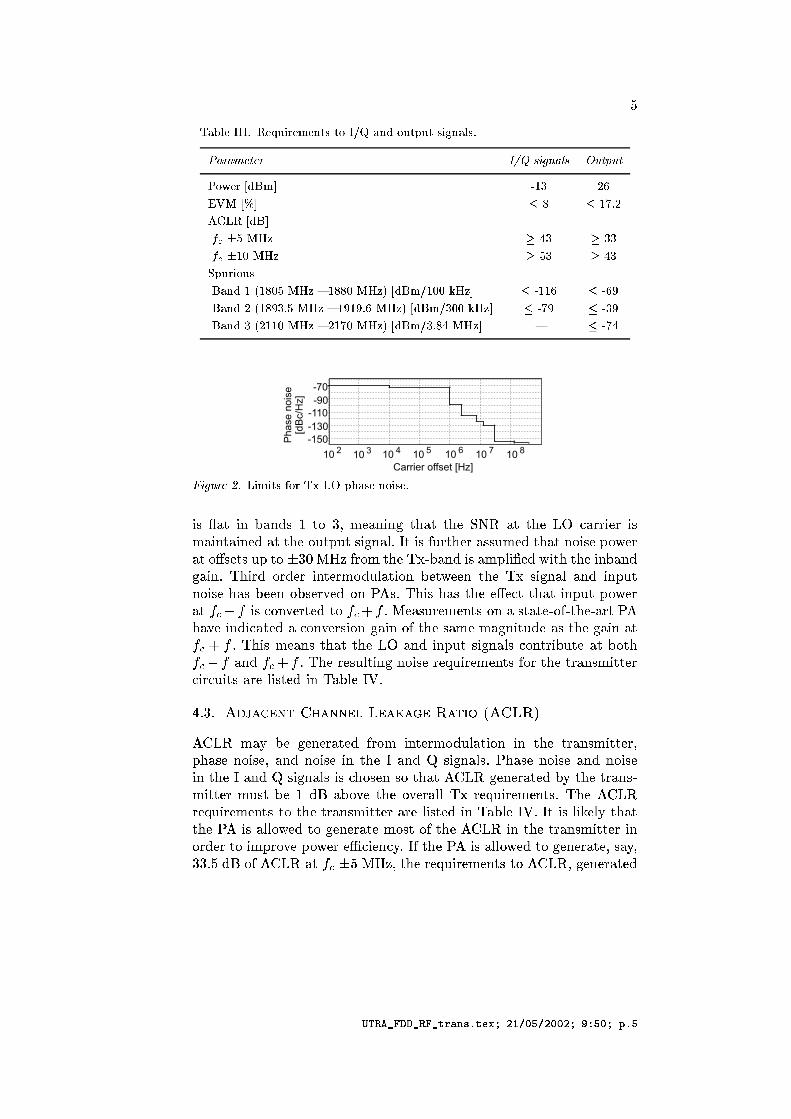
¸5³nÄIº § bÅa©E§6.®I¥ «§°¯§°¤V±²±¬¶Q½ ³@¤I¨¶.®I±¬ÀI®I±a²i¥ Ì.¤3³nº ²LÅk'>@J>@H$9L=i9;J `lb< UTGB>@: l'gS= h3gV=¶nÇE§°« ¨ '¯0 Î 6 !)·& Å 6» ©# ¨ I " · 8 · "2 ¹ÆÀV®I«¥ ¶@®3²E³n¤3¨$ 8" · 8 · à ¨ '¯½ 8!8#Ï Î "! Î!E³n¤3¨ 6  Š" · SÅ !$· à ¨ ¯½ !848#Ï Î Î E³n¤3¨  6 8 · 6 18 · à ¨ '¯½ Å · Î
! #"%$'&)( *+( ,.-/102'345&67%8:9-<;>=%0(?-@;A
B1CEDGF%HIB?JLKFMJONCQPRHSUTWVYXEZMF%JB?JO[\H]GF%H^H]Z`_WacbdFMH^H]ZRefdgMF%hhB1ZhiB1CXiF%B1JjHF:B?JZkNiF%HYH]ZlSnmHomHYCB1[nJGF:p.qjr!HsB1CYt@mhH]OZhuF%CCvmXEZkNEH]GF%HYJS)B1CZuoSMwxZhF%HySnzCZHCymoHS|T:~cst@hSnXH]ZxxW!KGF%JNB1C#F%XEop1B?ZkNwuB?H]H]ZsB1JjKGF%JN[WF:B?Jqs+]B?hNLS:hNZhiB1JjHZhXESNmpF%HB1SnJKZHwxZkZJH]ZxCB[:JF%pF%JNB?JomHJS)B1CZ]F%C5KZkZJ`SnKCZhnZkNSnJ'cCqO+]BCc]GF:C5H]ZZzZkgH5H]GF%H5B?JomHoSMwxZhF%H+MRiB1CsgkSnJj)ZhHZkNHS%`yqjZMF%CmhZX^ZJjHCuSnJFCHF%HZSnt@!H]ZvF%hH>']GFk)ZB?JNB1gMF%HZNFgSnJWnZhCB1SnJ[WF:B?JS:tH]OZ5CFMX^ZcXiF%[nJB1HmNZF%C+H]Z[jF:B?JQFMH Lq+]B1CX^ZMFMJOCcH]GF%H5H]ZefF%JN`B?JomHCB1[nJGF:p1C5gkSnJjHhB1KmHZiF%HcKSnH]%'QF%JNRMOqW+]Z5hZkCvmOp?HB?JO[JS)B1CZchZjmB?hZX^ZJjHCut<SnhxH]ZlHhF%JCXEB?HHZhgkB?hgmB?HC5F%hZp1B1CHZkNQB?JQ>FMKOp1Zr!q
q Tq ¡¢£¤¥¦§¨c©£¦¦¥ªQ«s¥W£¬£¥`®£§G¯.°²±v ¨c«x®³l´xebµXiF¶²KZ·[)ZJZhF%HZkN¸t@hSnX¹B?JWHZhXESNmpF%HB1SnJºB?JºH]Z»HhF%JCvX^B?HHZhVo]F:CZEJS)B1CZnVYF%JN»JS)B1CZ^B?J·H]OZ^rF%JNU¼½CB1[nJGF:p1CqY]GF:CZEJS)B1CZRFMJON\JOSnB1CZB?JH]Z5r+F%JNQ¼¾CB1[nJGF:p1CuB1Cg]OSnCZJQCSH]F%H+l´xeb¿[)ZJZhFMHZkNiKj¶IH]ZcHhF%JCX^B?HHZhXmCHK'ZPiNÀÁF%KSM)ZIH]ZISM)ZhF:p1px\hZk)mOB?hZX^ZJWHCqx+]Zl´xebhZk)mB?hZXEZJjHCcHSH]OZcHhF%JCXEB?HHZh5F%hZp1B1CvHZkNRB?JQ>F%Kp1ZrqrHlB1CpB?ÂnZkp?¶H]FMHH]Z'¾B1C5F:p1p1SMwxZkNRHS[)ZJZhFMHZX^SnCHlSntH]OZl´+eb¿B?JRH]ZHhFMJOCvX^B?HHZhcB1JSnhNZhsHSB?XohSMnZco'Sw+ZhuZÃ^gkB1ZJg¶)qrt'H]Zc'ÄB1CF:p1p1SMwxZkN^HS[)ZJZhFMHZnVWCF¶)VT)Tq ÅlNÀUSntl´xeb¾FMH%s|Å5cnV)H]ZuhZkjmB?hZX^ZJjHC+HSl´xebV[nZJOZhF%HZkN
Æ%ÇkÈÉ%ÊËkÌkÌ%ÊÈkËÊÍÎkÏÐ:ÑjÒÍ%ÓÔOÕ+Ö%×ØÙMÚkØkÖÙkÙMÖjÕsÛOÜ<ÚÙÕÝGÒ.Ú

9
*T5, 1I752 7ê46\^B71 X 4q1I752éO1346,È75z\^46,B~546q',Ê\Q75.-T,V134T,Æ2*2 ;7*B,Æ46T\^r1IT\oz374ezB[\Q7rT,.-6~z2 X 1IT\oz37 \Q7 +'|04È1ÆB,4°5zVó$7 6'1VÊ6,~z4°465\Q.1V X ,)ó$1Æ[Tz2O,Æ46.-n\Q',F| NaéE,@-T¬zB-6~Ê1V7Æ,FzBr4°62O,.r\^Æ,Æ4)zB71$B,.7,@-.1 XX ,., X E\^404T\Q~qé X nzÈ46é',ÆÆ\Qi| Na by#5,.-n,.¬z3-n,BE\^7 65\o40ózB-6''zB7 X eT5,| Naí\o4$4°é',ÆÆ\5,Æ2a5 5HH > H B*) 3> H 8 F62I@H3G5;BKJ M
xY/ \^4],.75,.-@1In,Æ2 r~Ê1I7* 2O\;$',.-n,@7rÆ\Q-T.5\Q\Q~é',.-6¬,Æ.n\^zB754Æ25,.é',.752O\Q7zB7ó$5\^T6-.1V74°~\Q6n,.-1I-nT5\QT,Æ.TO-T,Ê\^4]46,Æ2E)æ5zB-1e2O\Q-n,Æ.Oé5ì;.zB7rB,.-T4T\^zB7T-@1I7546~\QTT,.-S'65,4T\^B75\5V1I7*]b13.TzB-n4[1V-n,Ib75éOO4T\^B71 X \Q7r1I752éO134T,-n,.ì46é'zB7546,e1I7521I~qé X \Q6525,-T\^éOé X ,B ;ì]1V72 70ì;\Q~'1 X 1V7.,B)é51346,7z\^46,B)\Q7*T,.-Tì~zr2O X 1IT\^zB71I752 WÍX ,V1I1I,BVy#,F-n, X 1Vn\^zB7',.Ló,Æ,.7qxY/ 1V72z$'4T,.i-nz3~T5,1Æ,@-.13,r13\Q7aE134$ó, X^X 1I4T5,-T, X 1In\^zB7E,.;ó,Æ,.7xY/ 1I75265,2O\;$',.-Tì,.75Æ,q',.;ó,Æ,.765,È13.61 X éO1346,q-T,Æ46é'zB7546,Ê1I7526,q\^2O,V1 X éO134T,-T,Æ46é'zB7546,1I-T,2O,Æ46.-n\Q',Æ2\Q7 by#5,,)$',Æ.n4z3Qbì[1I752 70ì;\Q~1 X 1I75Æ,B\Q7*1I72éO1346,75z\^4T,01I752\Q7*n,.-6~z2 X 1IT\^zB71I-T,2O,Æ46.-n\Q',Æ2È\Q7 bBó$\^Te1 X 4Tz[,4/é X 13\Q754xzSónzÆzB~5\Q75,575ÆzB-6-n, X 1Vn,Æ2 ÆzB7*6-n\QOOnzB-T4ÈzB]xY/ ;7 DbF W X ,V1IB13,e\^42O,Æ4T.-T\QE,.2Í*65, èý &ùBü.) .3ý¬ù>& þ 0ÿ.(B0z132°5466~,@7rT4zBç NFìz$'4T,.T4a\^41 X^X zVó,Æ22OO-T\Q70xY/è~,V134°O-n,.~,.7*n4Æ;O65\o4a\^41 X^X zSó,Æ2aVró\ X^X1Æ,F75z0,)$E,..)zB7xY/Vy#,Fnz3.1 X 1I~zBO7*)zB1ÆB,.-@13,F0/ ,.75,.-.1IT,Æ2*T-@1I7546~\QTT,.-x~546F75zBx,4/OÆ,.,Æ2# ï -T~4Sy#\^4 X ,V132O4)nz[6,#-T, - 5\^-T,.~,.7*n4éO-nzBé'z46,Æ2e\^7y1I X ,;
EÙ iß'â % aáãiÞ2OÜ5Ý;ßÞ 1ã?Þ*âBÝ "! ß$#ÈÜ&%ßÜ 'X*ÞIãiß'Ü/#Þ 1Ü Vâã 'X*Þ
y#5,]3/1I752y0/Ê-T, - 5\Q-T,.~,.7*T41I-n,Y4°5~q~È1I-n\Æ,Æ2 \Q7ey)1I X , ;C9 B*) B@+ B H('7> )*) 9B*; GI@HB:4B:23;A;7e6,]-n,.Æ,.7r0B,V1I-T4S2O\^-T,Æ.6ì;ÆzB7*,.-T4T\^z37-n,Æ.,Æ\Q,.-T4[1Æ,,.~,.-nB,Æ2 ¬z3-0ð]/1IéOé X \^V1Vn\^zB754Y1V72È~Ê1I7*ÊÆzB754T\^2O,.-06\^401I-nT5\QT,Æ.TO-T,65,[é5-TzBé',.-06z\^Æ,[¬z3-ð 4°r46T,.~4Æ5|îé1I-6n\^. X 1I- X 7\^Æ,¬,V1VTO-n,0\^4FT5,b13.F6'1V#6, X 1V-n,$'1V72ìó\^2O6~Ê1V,Æ4,+ ìNç[/| 46r46T,.~4 X ,Æ4644T,@746\Qn\QB,ÊTzVó$1I-n2O4 1 C75z\^46,e1V72ç Nz$'46,.xéO-nz3 X ,.~4F\Q7O,.-T,.7*Fnz]2O\Q-n,..Tì;ÆzB7*B,.-n46\^zB7È-n,ÆÆ,.\^B,.-T4S|7,4/51I~qé X ,zB$1Êä0y$|[å3æ)çYç 2O\Q-T,Æ.Tì;Æz37rB,.-T4T\^zB7£-n,.Æ,Æ\Q,.-\o44°zVó$7\Q7æ)\^BO-T, a|7\Q7rT,.-T46@13,-1.3ü"Túb.3õnõQ)^ýbö.÷ þ +Fæxÿ0\^4[546,Æ2TzÊéO-nzVr\^2O,Ê1ITT,.7*1In\^zB7zBFT5,y0/ì X ,V1V13,]46\^B71 X y#5,1I~zBO7*0zB1ITT,.7*1In\^zB7e-T, - 5\Q-T,Æ2 i-TzB~ 6\^4 X T,.-2O,.éE,@72O4#6,Y2O\ $',.-T,.75Æ,]\Q7Ê-T, - 5\^-T,.~,.7*n4Tz\Q75ìb1I7521I752ÊzBO6ì;zBiìb1I752 X \^7Oì,V1I-T\^;By#5,zr1 X \^4)nz1I6T,.7r1IT,65,$y0/ì;46\^B71 X 4°TT1Ix-T, - \Q-T,.~,.7rT4Tz>?:D[1V72 > ?@ + ¬zB-$6,Y4°5546, - 5,.7*]æ X zTr4Y1V-n,0T5,]4n1I~,0¬zB-$'zB6T5,3/1I7521I752zBOTì;zBiìb1I752EI|04646O~\Q756'1V65, +Fæ134F1I7q\Q754T,.-6n\^zB7 X z464
EFG!HI1JKKI1GJI1L!MN4OQPSRLTVUXWZY[1\1]^\Y4]]YSW`_Xa%^4]bW3c*R/.

¸O³nÄIº § FŹƮV¯#¯#³@« ¾ ¶nµO±«³@¤3² ¼ §°¥ ´.§°««§6.®I¥ «¬§°¯#§°¤S±b²;Å
AhV>@J>@H$9;=i9LJ;l 8xhS>@J>@H$9;=¬9;JLla¶.¥ ²¬§¦3Ì@®I«¬§E ¨ I ! ®I±¬ÀI®I±a¤I¶@¥Q²i§E ¨ ¯½& ¹Æ§°º § ¼ ±¬¥ ´Æ¥ ± ¾ ¨ I E³n¤3¨ Î 6 6²¬±³.¨;Å ¼ É*År " · à E³n¤3¨ 6 Î 8! 6 ¤3¨0³.¨bÅ ¼ É*År 8 · à E³n¤3¨ Î 8©E§°¯$³n¥ ¤I¥ ¤IÌ$©'ÁSÎ^Ä3³n¤3¨ " » ©# ¨ I 8 6,86 " · " ! " · ¸'ÁSÎ^Ä3³n¤3¨ 8 · R?¤S±§°« ¼ §°ÀI±EÀ3¶.¥ ¤S±b² ¨ '¯E .e¥ ¯FÄ3³@º ³n¤ ¼ §  8 · à eÎ 6 » ¯ÀIº ¥ ±®3¨V§E ¨ I @Å Â " · à 5É3³@²i§ ¨V§°ÌR " ÂQ¸EÁÆÎoÄI³@¤3¨ à " » ´.§°«³@Ì@§x¶ ²¬§°± "  F 8 Î 6,8Sà · à eÎ 6 » ¯#ÀIº ¥ ±®3¨S§0 ¨ I 8 Å Â&! 18 Î 6,86 " · à eÎ " 5ÉI³.²i§x«§6²iÀ3¶.¤3²i§ ¨V§°Ì
¹S©D R ¨ Î 6R
-5< UngSJb9? ¿ ¥ «¬§ ¼ ±Î ¼ ¶@¤V´@§°«b²i¥ ¶@¤0«§ ¼ §L¥ ´@§°«°Å
zBX#2 S6,x-T, - \Q-T,Æ21ITT,.7*'1Vn\^zB7~54°',#1I X ,V134° F2 i-nzB~ 9 )/ nzÊï )rï9q/3y#5,éO-nzBé'z46,Æ2 X zTe-n, - 5\Q-n,.~,.7*n41V-n, X \o4°n,.2\Q7 y)1I X ,y#5,r13\Q7O525B,.0-n,.éO-T,Æ4T,.7*T4q1ÆzB~qéO-nzB~\^4T,',.;ó,Æ,.7 3 1V72+>?:A1V72134x4°5T46,.B,.-.1 X O2O,.T4FÆzB X 2È',$~Ê1I25,$-n,Æ4° X n\Q75\Q7È2O\;$E,.-T,.7*$46,.n4zB 3
1I752 >?@A5, - 5\Q-T,.~,.7*T4YTz 3 1I-T,[¬zBO7254T\Q75æO-n\^\^4 = 40V1I4TV132O,[¬zB-6~OìX 13,ó$\ X ,-n, - 5\Q-n,.~,.7*n4nz1>?@ + 1I-T,ȬzBO75254T\Q756,ÈV1346V132O,ʬzB-6~ X 13,2O,Æ4T.-T\QE,.2\Q7( 9;'y#5, +Fæë\^4134646O~,Æ2nz',é13464T\QB,Ê1I752 6*4Yó\Q65zBO4T\^B75\5V1I75Æ,ó$5,.7&ÆzB75Æ,.-67\Q75 X \Q75,V1I-T\QLYr,ÆÆzB752 zB-T2O,.-75zB7Oì X \Q75,V1I-n\Q;î\^4zB7 X .-T\^T\^V1 X ¬zB-È X zTr4ezBé',.-.1Vn\Q75ë1IÈ'1346,.1I752&1I752î\o4ÈT5,.-T,.¬zB-n,zB7 X 46é',ÆÆ\5,Æ2 ¬zB-ÈT5,ëûùC+*öÆ÷ þ /]ÿe1I752î65,-1.Iõ.ö -1.3ü*" )^ýböÆ÷.3ü*" .3ûú*)Qù #ö.÷þ ær|[ÿ. b7eT5\^4Æz37b5BO-@1In\^zB7aOy0/rì X ,V1I1I,]zB7 X 46,.n4$T5,[-T, - \Q-T,.~,.7rT4YTzB&ü&3ùiõ.ö .3ûúX)^ù #ö.÷0üôû -nö.÷ þ B0| Iÿ., - 5\^-T,.~,.7*n4#Tz>?:D#-T,.éO-n,Æ46,.7*ÆzB~qé5-TzB~\^4T,Æ4ÈE,.;ó,Æ,.7Û5zVó ~5T&2O\o4°TzB-TT\^zB7 é'zVó,.-65,/ 1V72 T5, æ| 1I-T,e1 X^X zSó#,.2£Tz,.75,.-@1IT,By#,O525B,.\Q7£y)1I X ,È 1 X^X zVó4/ Tz
EFG!HI1JKKI1GJI1L!MN4OQPSRLTVUXWZY[1\1]^\Y4]]YSW`_Xa%^4]bW3c*R

¸O³@ÄIº §yFÅ©E§ ¼ §°¥ ´@§°«EÄIº ¶ ¼bÏ «§6@®I¥ «§°¯#§°¤S±²LÅa: f,:LK At/. Ek - AtY` -It ³n¥ ¤5 ¨ " Î 8 ¨ I &! ?¤V±¬§°« ¼ §°ÀI±'ÀB¶@¥ ¤V±² ¨ '¯E$ 8 · à $ " · à 6 $Â^¸'Á à 6 $  8 Î 618Æà · à eÎ eÎ! 8 8$ "! ,8 Î 6186R" · à eÎ eÎ! 8 8
,.75,.-.1Vn,~zB46[zBFT5,q25\^4°nz3-TT\^zB7é'zVó,.-S|#Y5\^Bi-T, - 5,.75.z $E46,.n4ÆE65\^4~,S1I74$T1I4T,.,.~\Q75 X 1I-T46e-n, - 5\Q-n,@~,.7*n41I-n,[~È132O,[nz æ|50zVó,.B,.-V4T\Q75Æ,x6,)-n, - 5\Q-n,.~,.7*n4)nz >?:DF1I-n,)134T,Æ2zB7\Q7*n,.-6¬,.-T\^75046\^B71 X 41I n\Q~,Æ4T5, æ|î.OTì;z$ei-n, - 5,.75.OT5\^4\o4F75zB$Æz3746\^25,@-n,Æ2ÊTz',[1@-n\Qn\^V1 X 2O,Æ46\^B7é1I-.1I~,.T,.-V5z3~,0nz X ,.-@1I75Æ,Æ4#~4°$',[4°é',ÆÆ\,.2e¬zB-1 X^X X zrTÈr13\Q754#nz1I.ìÆzB~q~zr21Vn,02O\;$E,@-n,.7*$1I-T\?1In\^zB754Æ*y#5,Æ4T,0nz X ,@-.1I75Æ,Æ4#-T, - \Q-T,1I7132O2O\Qn\^zB71 X~Ê1V-n\Q7Tz',éOOzB7ÈT5,é',.-T¬zB-6~È1I75Æ,é'1V-.1I~,.T,.-n4\Q7y)1I X , 1346,Æ2zB7T5,Æ46, X zT-T, - \Q-T,.~,@7rT4S\Q#\^4 X ,V1I-FT1I~,.,.n\Q7565,T,Æ464°é',ÆÆ\S1In\^zB754X \^46T,Æ2\Q76,qä0y$|[å3æ)ç[ç 46@1I7521I-n2\o4Yr 75zÊ~,V1I754O7O-n,V1 X \^4°n\^B ,Æ\Q751I X ,ÈTz zBé',.-.1IT,ÈB0| 1I1e75z\^4T, 5BO-T,zB 2 ~È1IB,Æ4T5,2O,Æ46\^B7ÍzBT5\^4 X zT X ,Æ4T4q.-T\^T\^V1 X ;7£T,.-T~4qzB X \Q7,S1I-n\Q;x6,ÊÆzB7*n\Q7*5zB4éO-n,.4T,.75Æ,zBFT5,qy0/rìL46\^B71 X 4T,@n4]T5,~z4°4°T-T\Q7,@7r-n, - 5\Q-n,.~,.7*n4TzÊT5,-T,ÆÆ,Æ\QB,.-Vy#5\o4FéO-nzB X ,.~ ',ÆÆzB~,Æ4 X ,Æ464$4T,.B,.-n,[ó$5,.71I7\Q7*n,@-n4°.13B,Y1I752é'1I4T40 X T,.-\^454T,Æ2E ï H!862;A 4 @ 3!3B H(' 7 >)*) 9B; GI@8HIB:4B23A
y#5,[2O\Q-n,Æ.Oé5ì;Æz37rB,.-T4T\^zB7T-@1I7546~\QTT,.-[1I-TT5\Qn,Æ.6O-n,\^4$\ XoX 54°T-@1In,Æ2e\Q7æ)\^BìO-n, 5*+ ,@7V1 X . X 1IT\Q75e65,zBO6é5O]75z\^46,B\Q7rT,.-T~z2 X 1In\^zB7\Q7T5,q+E|
DAC
da
QUCd
a
LO
VGA FI PA
to duplexfilter
90o
DAC
-5< UngSJb9? ¿ ¥ «¬§ ¼ ±E®IÀIÎ ¼ ¶@¤V´@§°«b²i¥ ¶.¤0±¬«b³n¤3²¬¯¥ ±±§°«LÅ~54°0E,[ÆzB754T\^2O,.-n,Æ2EIb0\^4Y1I4T4°5~,Æ26'1IT5,]Æz37rB,.-T4T\^zB7r13\Q7\^40, - '1 X Tz
EFG!HI1JKKI1GJI1L!MN4OQPSRLTVUXWZY[1\1]^\Y4]]YSW`_Xa%^4]bW3c*R

T5,13.61 X r13\Q71I752T1I)T5\^4FV1I7q',#.1IB,.7\Q7rTz13ÆÆz357*F*q25z35 X \Q75[T5,,)$',Æ.n\QB,07z\^46,1I752Oó\^2Ta| 4T,@$zB' X zTq-T, - 5\Q-T,.~,.7*T4nz\Q75ìb1I752r1I\Q7B0æ&1I752| Na \^4éO-TzBé'z4T,Æ2\Q7y1I X ,:@B0z\^46,Ê1I752r13\Q71I-T,Ê134646O~,Æ2
¸O³nÄIº § bÅa¸«b³n¤3²¬¯¥ ±±¬§°«ÄVº ¶ ¼;Ï «§6@®I¥ «§°¯#§°¤S±²LÅa: fV:°K FvEc 5dt -O` kt ³n¥ ¤ ¨ I 8 Î 6 6R"ª ¨ 8 6 "» ©= ¨ I " · " !" 8 · "2 " " "
ÆzB7546@1I7*)¬zB-F1 X^X i-n, - 5,.75Æ\^,Æ4xO72O,.-xzB54T,.-61IT\oz37B,4/Æ,.éOF¬zB-65,$+E|Ió$5,.-T,10*13\Q7qzBEï2 1V721 B0æzB2 1I-T,134T4°O~,Æ2¬zB-)1I752 Y1I752T5,$\Q~È13,zB65\o4x1I752EB0æ\^4F4°éE,.Æ\,Æ2È46z[T5,$zVB,.-.1 XoX -n, - 5\Q-n,.~,.7*$nz[75z\^46,\Q7q'1V72\^4~,@Vyz~,Æ,.065,~zB-T,1I-T46-T, - 5\^-T,.~,.7r[nz75z\^46,\Q71I752 5T5,)^ýböÆ÷ þ æ °ÿ#~5461I6n,.7*1In,]6\^41I7521I752T5,\^~È13B,[ó\^6ï ]2 + 5,.7T5,$T-@1I7546~\QTT,.-$\^4zBé',.-.1IT,Æ21IFT5,$\^B5,Æ4°#i-T, - ,.75.O6,\Q~Ê1I,~Ê1.',z$'4T,. )/0i-nz3~è6, X zVó,.-,Æ2O,YzBaT5,[y0/rìb1I752EOy#5,.-n,.¬zB-T,B5æ ~546éO-nzVr\^2O,eï 2 z301ITT,.7*'1Vn\^zB7£1I)q/Èz$'4T,.T4i-nz3~ 6,y0/ìb1I752EyzqzB~\^æ 65,]2OOé X ,4/ X n,.-0~546éO-nzVr\^2O,L 2 zB)y0/rì;3/e\o46z X 1IT\^zB7\^7T5,$Z/1I752Ey#5,$nzB@1 X |0 N ,.75,.-@1In,Æ2qr <Æ\Q-T.\QT4S V1V7',¬zBO72i-TzB~êT5,| Na zB,V13TÆ\Q-T.5\^S D A 546\Q7È - Eïó$5,.-n,1 X^X | Na 1I-T,[-n,.éO-T,Æ4T,.7*T,Æ2\Q7Ê7rO~E,.-T4Æ
1 A *
þ ïÿ
|04ó$134x65,V1346,¬zB-T5,$-n,ÆÆ,.\^B,.-STz X ,.-.1I75Æ,Æ4FzB7 X z6-n, - 5\Q-n,.~,.7*n4#~546',F46é',ÆÆ\5,Æ2\Q7z3-n2O,.-)nz013ÆÆzB~q~z21In,2O\ $',.-T,.7*)1I-n\?1Vn\^zB754SVy#5,éO-TzBé'z4T,Æ2r13\Q7O52O,.q~,V1I754T1IqT5,1.,.-@13,ezBOTéOOé'zVó,.-ÈzBT5,ø.ôb."I÷,.3ýô÷TöôSú@1&3üX$IöÆ÷@ý;ö.÷ þ 7Yä5N$ÿ\o4qì2 ~ey#,éO-TzBé'z4T,.2ë W é'zVó,.-\o4qì9 2 ~yzezBO.1I\^765,é5-TzBé'z46,Æ2)rè65, W ì X ,S1I13,~54°T*54',ì°ï 2 z3-X ,Æ4T4Æ bET5, W é'zVó,.-\^4F\Q7.-T,V1346,Æ2E-T, - 5\Q-n,@~,.7*T4#nz] W ì X ,V1I13B,',ÆÆzB~,Æ4~z3-n,1I-n4°ay#, -n, - 5\Q-n,.~,.7*TzÍz356éO5Ê7zB\o46,\Q7î'1I752 46,.T4e1I-T46-n, - 5\Q-n,.~,.7*n4Tz75z\^4T,\Q7T5, 7Yä5N0 b~È13,~\ /O\Q75 \Q765,+E|èéO-n,@,.7*T4æ xi-nzB~ -n,.~zVr\Q75È65\o4$75z\^4T,BO',ÆV1I546,[T5,]\Q~È13,]\^4\Q7546\o2O,[65,]y0/ìb1I752Ey#5,zB7 X ó$1Ænz1 XoX zVó z3-1I7\Q7.-T,V1346,Ê\Q76, 7Yä5N 75z\^46, 35-T,B\^4Tz1I6n,.7*1In,[1I752 \Q7ÊT5,]25é X ,4/ X n,@-V
EFG!HI1JKKI1GJI1L!MN4OQPSRLTVUXWZY[1\1]^\Y4]]YSW`_Xa%^4]bW3c*R2_

!)
EÙ %ß'ÜaâSáIãißÜ
;7T5\^4é'1VéE,@-VE146,.YzBFä0 T-@1I754TÆ,.\^B,.-]-T, - \Q-T,.~,@7rT4[1Æ,',Æ,.7 2O,.-T\Q,Æ2i-nzB~òT5, ä0y$|[å3æ)çYç46@1I7521V-n2E+ X 1I54T\Q X , X zT -n, - 5\Q-n,.~,.7*n4¬zB-e12O\^-T,Æ.6ì;ÆzB7*,.-T4T\^z37í-n,ÆÆ,Æ\QB,.-1I-T,éO-TzBé'z4T,Æ2Eæ)ç[çzBé',.-.1Vn\^zB7 ~,V1I7546'1V3/ 1I752íy0/í~È1Æí',Í13.T\Q,Í4T\Q~ X @1I75,ÆzB54 X ]y#\^4-T,Æ4° X T4\^7 1ë1I-T46-n, - 5\Q-n,.~,.7*nzeZ/ X \Q7,S1I-n\Q;y0/4°é',ÆÆ\5V1In\^zB7541V-n,6-.1I754 X 1In,Æ2 nz X zT-n, - 5\Q-n,.~,.7*n4e¬zB-125\Q-T,Æ.OéOì;ÆzB7*,@-n46\oz37 T-@1I7546~\QTT,.-V#æ)ç[ç zBé',.-@1In\^zB7~,S1I74)T1IF1I7æ 1I752ìbé'1I4T4 X T,.-F\^4)-n, - 5\Q-n,Æ2\Q7qT5,$y0/T13\Q7qnz[-T,Æ2.,y0/ìb75z\^46,F\Q7]T5,F3/[1I752a b4°5zB X 2',x75zBn,Æ2[61I-T, - \Q-T,.~,.7rT4éO-TzBé'z4T,Æ2\Q7T5\^4#2Oz@5~,.7*1I-T,1346,Æ2È25\Q-T,Æ. X zB7È46é',ÆÆ\5V1IT\^zB754S;7éO-.1I.n\^Æ,B4TzB~,~Ê1V-n\Q7£~4°',\Q75 X 2O,Æ2ëTz@1I,e\Q7*nz13ÆÆzBO7*b1IO-n\^V1IT\^zB7£nz X ,.-@1I75Æ,Æ41I752zB6,@-]575Æ,.-6.1I\^7*T\^,Æ4S| X 46z5a\Q\^4]ózB-T67z3n\Q75e61Iä0y$|Yå3æ)ç[ç \^41I7 \Q7*n,.-6¬,.-T,.7Æ, X \^~\Qn,.24°r46T,.~ nz1qó\^25,,1/T,.7*V'ó$,.-T,1I7r 132O2O\Qn\^zB71 Xé',.-T¬zB-6~Ê1V7.,]46O-Té X 54zB7ÊT5,Yä0 ó\ X^XEX ,V1I2eTzq\^75.-T,V1346,Æ24°r46T,.~ V1Ié13Æ\Q;0,.75Æ,B#75,.;ózB-TîéO-nzVr\^2O,.-n4~È1ÆëéO-n,.¬,.-ä0F4Êó\QTîE,@TT,.-é',.-T¬zB-6~È1I75Æ,Bä0ë~Ê1V7rOb13.65-T,.-T4Y~È1Æ6,@-n,.¬zB-T,ó\^4° nz,4/Æ,Æ,Æ2 4°éE,.Æ\V1Vn\^zB754YTzr1I\^7~Ê1V-TB,.04°1I-n,.4S
% d*ÞÜaâD
@Å «b¨ §°¤I§°«³@±¬¥ ¶@¤E5³n«±¬¤I§°«b²iÉI¥ ÀI5«¬¶ i§ ¼ ±Y O à 6,8!8 .× ¢©³@¨V¥ ¶¸«b³n¤3²¬¯¥ ²²i¥ ¶@¤³n¤3¨0©E§ ¼ §°ÀI±¬¥ ¶@¤Â^ª ¿)¿xà ×3¸§ ¼ ÉV¤I¥ ¼ ³@º*¹ÆÀ3§ ¼ ¥ ¦ ¼ ³@±¬¥ ¶@¤ 6R" Å 8 x´3Å IÅ 8 Å 8 Å6 Å@§°¤3²¬§°¤*× ÅFÅ ×a¸)Å'EŶ.º ¨V¥ ¤IÌV× Å©)ÅIi´@§°«b²i§°¤*×¹3Å ³n®I«b²i§°¤*×a©)ÅFÅ'©E§ ¾ ¤I¥ ²²i¶.¤*×VÅxÅÆ·[¥ ÏÆÏ §°º ²¬§°¤*×k'ÅkO§6¨S§°«b²i§°¤*×V·Å Å.§°¤I¤I§°«L×Ƴn¤3¨$¸)Å ³n«b²i§°¤ 61848!8 × ©aª©E§ ¼ §°¥ ´@§°«©E§6.®V¥ «¬§°¯#§°¤S±b²5µ^¶@« '¿ · » ·[¶@ÄI¥ º §.®V¥ ÀV¯#§°¤S± Å [<<:LJbf19>@R@9Æf@gSJLGB>@: 6@à ×646 !VÅ
Å ·]³@¨I²i§°¤*×Å !6,848 @× ¹Æ¥ ¯F®Iº ³@±¬¥ ¤VÌ ´.§°«³@º º§°«iµ^¶.«¬¯$³n¤ ¼ §'©E§6.®I¥ «§°¯§°¤V±²rµ^¶.«r¸«b³n¤3²i¯#¥ ±Î±¬§°«b²¥ ¤ i·]¸ 6184848 ª ¿)¿ ¢²i§°«.®I¥ ÀI¯§°¤S± Å ?¤ gSJf°hI9>@Gqc5f@GTjL9LJb9;GD:;9f@G0<QJb9;: 9Llbl8I9':@=ÆGBf@: f;UnwnÅ ¶@¤3¨V¶@¤*×:5¤IÌ@ºQ³n¤3¨×VÀVÀ*Å ",8 Å
VÅ ·]³@¨I²i§°¤*×OÅ × ÅFÅ.§°¤I²¬§°¤*×5¸Å » ¯±¬¶@µQ±°×5©ÅxÅ©E§ ¾ ¤I¥ ²²i¶.¤*×IÅ*Å·[¥ ÏÆÏ §°º ²i§°¤*×¹3Å ³n®I«b²i§°¤*× ÅÆ©)Å!i´@§°«²¬§°¤*×I¸)Åk'Å ¶@º ¨V¥ ¤VÌI×Ƹ)Å ³n«b²i§°¤*×I³@¤I¨$·Å Å.§°¤I¤I§°« Q6,8!8 @× ©ª©E§6.®V¥ «¬§°¯#§°¤S±b²µQ¶.«¢¸© » ½nª ¿)¿ ¸«b³n¤ ¼ §°¥ ´@§°«b² Å ?¤ c5f@GTjL9LJb9;GD:;9kJfV:;9b9';@<QGVUTlxjLf@Jk c .n×M5¶.ºoÅ )¶@µ Å » ³nº ÄB¶@«Ì ¿ §°¤I¯$³n« Ï ×3ÀIÀ*Å 6,86 Å
" ÅÄO¥ ¯#¥ ¤IÌ.²¨V¶@«¬µ^§°«L× ¿ Å × » Å a¶.º ¯0× Åª¥Q²iÉ ¼ §°«b³n®I§°«Lש)ŸEÉI¶.¯#³.²;× » År¹ÆÀI«¥ ¤IÌ@§°«°×3³n¤3¨[©)Å §°¥ Ì.§°º V× ?¯#ÀI³ ¼ ±0¶nµ$¹ » ©aª³n¤3¨ iªª¥ º ±¬§°« É3³@«³ ¼ ±§°«¥ ²i±¥ ¼ ²¶@¤e¢·]¸¹¸«³@¤3² ¼ §°¥ ´.§°«¹ ¾ ²¬±¬§°¯L§°«¬µQ¶.«¬¯$³n¤ ¼ § Å` v: =^J>@lLf@GI<<:LlNIwnHhSf@lb<QgSHÀIÀÅ ! " !VÅ
!SÅ&¹Æ³@Ì@§°«b²;×0©)Å Å × ?¤V±¬§°« ¼ §°ÀV±R¶.¥ ¤S±È³@¤3¨£¢a¤3¨V§6²¬¥ «¬§6¨ ©a§6²iÀ3¶.¤3²i§6² Å ` !8ÆJ>@GIlL>:°=^<^f@GIlf@G I9d=Æ<C:°gS: >@J#839':@=ÆG3f@: f;Unw#"%$'&()*Â Ã × 6 R Å Å5§ iº ÌƳ@³n«b¨× ÅÅ 6,8!848 ×* ¿ ³n±b³©E§ ¼ §°¥ ´.§°«Yµ^¶.«[±ÉI§È¢a¤I¥ ´.§°«²³nº·[¶.ÄI¥ º §q¸§°º § ¼ ¶.¯Î¯F®I¤V¥ ¼ ³n±¥ ¶@¤3²#¹ ¾ ²i±§°¯ ÂQ¢·]¸¹ à ÅEOÉ*Å ¿ Å5±¬ÉI§6²¬¥ ²;× » ³@º Ä3¶.«¬Ì¢¤V¥ ´@§°«b²i¥ ± ¾ × §°¤V±¬§°«xµ^¶@«
§°«²¬¶@¤ Ï ¶@¯#¯F®I¤V¥ Ï ³n±¥ ¶.¤Â Ã × » ³@º Ä3¶@«Ì$¢a¤I¥ ´.§°«²¬¥ ± ¾ × ¿ §°¤I¯#³@« Ï Å
EFGHI1JKKI,G!JIVLMN4OP RCLT1U WZY[1\4]^\Y4]]Y W_Xa'^4]bW0c*Rd[V]
áEÝaßÞã?Ý 1
öÆ÷."Iõ.öÆü
,ÆÆ,Æ\QB,Æ2\^40/ rB 2O,ÆB-T,Æ,\Q7 i-nzB~ê|[1 X ì'zB-neä75\Q,.-T46\^;ç[,@75~È1I-6'0,È\o4,.~qé X zS,Æ2*y, X \Q@1 X 0ç çY,.7O~Ê1I-61I752\^4.O-T-T,.7* X Í1I7\^7525466-n\?1 X +xa çq466525,@7rqó\QTÍ 6 N ð0-TzB5éç[,.7Oì~Ê1V-T
Z)oö]ùö4) Oö.üõ.ö.ü
,ÆÆ,Æ\QB,Æ25\^4/ rBO2O,ÆB-T,Æ,]\Q7e, X ,Æ.6-nz37\^],.75\Q75,Æ,.-6ì\Q7q¬-TzB~ |[1 X 'zB-nqä75\Q,.-T46\^;açY,.7O~Ê1V-T0\^4ózB-6134',Æ,.7\Q7T5, 5, X 2zB$n, X ,.ÆzB~~O75\oS1In\^zB7î\Q75 X 525\Q75~\^.-nzSó1.,, X ,..T-TzB75\^Æ4S1I7*n,.7O7134SF1V72~,S1346O-T,.~,.7*n,.T575\ - ,.4S0,£\o475zVóñ13464TzÆ\?1IT,éO-nzB¬,Æ464Tz3-1I|[1 X 'zB-nä75\^B,.-T4T\Q;
EFGHI1JKKI,G!JIVLMN4OP RCLT1U WZY[1\4]^\Y4]]Y W_Xa'^4]bW0c*Rd[[

IïX&3÷ -nö.ü0ûý>&@@ý
,ÆÆ,Æ\Q,Æ2 5\^4 / rB 00\^7 )Íi-TzB~ |[1 X 'zB-nä75\^B,.-T4T\Q;rç[,.7O~È1I-T*0,$ózB-Tr4#134)é5-Tz6,Æ.F~Ê1V7'1I,.-FzB7q1I-T\^zB54xn, X ,ÆÆz3~ì~O75\^V1IT\oz37éO-Tz 6,Æ.T4#1I752@5-6-n,.7* X 134xä0/yé5-Tz6,Æ.x~È1I713,.-1IFy, X \Q.1 XYç ç[,@75~È1I-6'E0,\^4Y,4/réE,@-n\^,.75Æ,Æ2\Q71I7*n,@7571Ê25,@, X zBéO~,.7*Va-@132O\ozÈi-n,.ì- ,.75.1V72~\^.-nzVó$1ÆB,2O,Æ46\o37¬zB-$~zB5\ X ,éO5zB75,Æ4S . Bü.3÷ ö! 3üùiõnõ!&3ü
,ÆÆ,Æ\QB,Æ2\^40/ rB i-nzB~ |[1 X 'zB-TÊä75\QB,.-n46\QLç[,.7O~È1I-6'\Q7 0,\^4.O-6-n,.7* X £éOO-n4°5\Q7 T5,+xa çq25,Æ3-n,Æ,e\Q7£T5,5, X 2zBæ B0/ W X \Q75,V1I-[1V7275zB7 X \Q7,V1V-~z2O, X \Q7O .3ü $&) ..I÷," ùö!)Qõ.öÆü
,ÆÆ,Æ\QB,Æ25\^4/ B 52O,ÆB-T,Æ,]\Q7 Yi-nz3~ |[1 X ì'zB-nä75\Q,@-n46\^;ç[,.7O~È1I-T#0,\^4.O-T-T,.7* X ózB-6\Q75ë1341I7 N 2O,Æ46\^B7~Ê1V7'1I,.-$¬zB-$T5, X 1I-nB,.ì;4TV1 X ,]æì. Nî2O,Æ4T\^37,)$'zB-601I|[1 X 'zB-Tä75\QB,.-n46\QL
EFGHI1JKKI,G!JIVLMN4OP RCLT1U WZY[1\4]^\Y4]]Y W_Xa'^4]bW0c*Rd[1Y

0\^4x-n,Æ46,V1I-TT\Q7*n,@-n,Æ4°n4$\Q75 X 525,'zB6Èæ1I752aæ N/ W 2O,Æ4T\^B7Ê134xó, X^X 1I4T-@1I754TÆ,.\^B,.-]1I-TT5\Qn,Æ.6O-n,Æ4Æ
÷Tö.ü B.3ô÷@õ.ö.ü
,ÆÆ,Æ\Q,.2\^4/ 3 F\Q7]n, X ,ÆÆzB~q~575\^V1IT\^zB754i-nzB~|[1 X 'zB-nä7\QB,.-n46\QLEç[,@75~È1I-6 \Q7 ;71B0zVB,.~',.-ï) )b[,2O,.¬,.752O,Æ25\o40+xa ç565,Æ4T\^4YzB7\Q7rT,ÆB-@1In,Æ2~\ /O,.-T4Y\^7=N/ W eT,ÆTO7z X zBB0,\^40.O-Tì-n,.7* X \Q7*z X ,Æ2ó\QT+E|í2O,Æ46\^B7 1Iæ£/\^.-TzçY,.\^Æ,Æ4Æ
O÷,&Sö!)Qõ$ûù) &)"3ùiü
,ÆÆ,Æ\QB,Æ25\^4]/ rB )1I752+Fa ç'25,Æ3-n,Æ,Æ4]i-nzB~|[1 X 'zB-nÍä75\^B,.-T4T\Q;ç[,@75~È1I-6'Y\Q7 9Í1I752 ï) ) )Í-T,Æ46é',Æ.T\Q, X ]æ5-nzB~ ì°ï) )b]5, X ,.265,2O,Æ46\^B7zB$1N/ W rìb1346,Æ2æì.NÛ-T,ÆÆ,Æ\Q,@-¬zB- ð+ Nç[/|r\Q7Æ,ï) ) E5,134]E,.,.74°r46T,.~ éO-nzBB-.1I~q~,È~È1I713,.-ó\QTB0zBr\?1B0,.LózB-6r4S5çY,.75~È1I-6'rózB-Tr\Q75z37Æì;B[,.7O'1V7Æ,.~,.7*0n,.T575\ - ,.4¬zB-ÈT5, ð ó\Q-T, X ,.4T4e,.Bz X 5T\^zB7a5NFO-6-n,.7*e-n,Æ46,V1I-TTÛTzBé5\^Æ4\Q7 X 52O,132ì1I75Æ,Æ26-.1I754°~\Q@åI-n,.Æ,Æ\Q,$n,Æ6575\ - ,Æ4Æ B0z2O, ÆzB7O¬zB-6~Ê1V7Æ,Fn,Æ4°T\^755V-.132O\^z-n,Æ46zBO-n.,e~È1I713,.~,.7*¬zB-Æ, X^X X 1I-7,.;ózB-64Æ$1I752ë4°4°n,@~ é',.-T¬zB-6~Ê1V7.,,.1 X 1IT\oz374Æ
EFGHI1JKKI,G!JIVLMN4OP RCLT1U WZY[1\4]^\Y4]]Y W_Xa'^4]bW0c*Rd[ G

!
X&3÷ -nö.ü B.3÷@õ.ö.ü
,ÆÆ,.\^B,Æ2Ê5\^4F/ rB 2O,ÆB-T,Æ,\^7, X ,Æ.T-T\^V1 X ,.75\Q75,Æ,.-6ì\Q7i-TzB~ |[1 X 'zB-Tä75\Q,@-n46\QLYçY,.7O~Ê1I-60\Q7 $1I752 6, ç0-V y,ÆT57a2O,ÆB-n,Æ,i-TzB~ |[1 X 'zB-TÈä7\QB,.-T4T\QL\Q7( ar\Q7.,Èï) )b5,'1I4Y',Æ,.7,@~ìé X zS,Æ2 134i X^X +x-TzB¬,Æ4T46zB-e1IÈ|[1 X 'zB-Tä75\Q,.-T46\^;ç0-V1I-T4T,.7 4T,.-6B,Æ4 1I4-n,.r\^,.ó,.-0¬zB- ;F LFF 1I752 +î\ X ,@|-T,V134$zB)4°é',ÆÆ\?1 X \Æ,Æ2-T,Æ4T,V1V-nT \Q7*T,.-Tì,Æ46T4x\Q75 X 525,75z\^46,65,ÆzB-TBB75zB7 X \Q75,V1I-$1I71 X 46\^4xn,ÆTO75\ - ,Æ4ÆOæn,ÆTO75\ - 5,Æ4Ææ N/ W T,ÆTO7z X zBB1I7522O\^\Q@1 X ~z2 X 1Vn\^zB7en,Æ6575\ - ,Æ4Æ ù>b.ö4) & ) Oö.üü'ö.÷
,ÆÆ,Æ\QB,Æ2 5\^4$/ 2O,ÆB-T,Æ,[i-TzB~ |[1 X 'zB-nä7\Qì,@-n46\^;xç[,.7O~È1I-T\Q7 0,\^4.O-T-T,.7* X ó#z3-Tr\Q75£1I41-n,.4T,V1I-TT ,.7Oì\Q75,Æ,.-1VY|[1 X Ez3-nä75\QB,.-n46\QLçY,.7O~Ê1I-6a0\^4Y.5-6-n,@7r]-T,Æ4T,S1I-nT\Q7rT,.-n,Æ4°T4\Q7 X 52O,~\^.-nzVó$1ÆB,~,V1I46O-n,@~,.7*n4ÆE75zB7 X \Q75,V1I-]1I71 X r4T\^4Æ1V72e~zr25, X \Q75ÈzB~\^.-TzVó$1ÆB,4T,@~\^ÆzB7525.nzB-T4S
EFGHI1JKKI,G!JIVLMN4OP RCLT1U WZY[1\4]^\Y4]]Y W_Xa'^4]bW0c*Rd[ <

PhD Thesis R04-1026, March 3, 2005.Texas Instruments Denmark A/S & RISC group AaU
On the Design of a Differential Common Collector Negative Resistance
P. Madsen, T. Larsen, J. H. Mikkelsen and J. C. Lindof
The 21th NorChip ConferenceRiga, Latvia, pp. 100-103, November 2003.
PAGE 91


!" " #!$%&' ##)(#!*+%# $
,-/.103254)67-98:<; =?>A@)BC.9D)-98FEG2C./67-98)=?>IHC258KJLAB5MONA252C.94P03QSRTRT-9MO67-98)=U>V258T4HW-98)6GXY).9QO6[Z\QS258KEGQS8T4TBA][:^I_<`/a[bAcSdebOf gOhUiG_jdUfkbVlm_jdUi1angOomprqtsVu)a<d/vwTcxseyPzg|h?~<paj e|7gOzdU ?_<gbO f ?<lm_jdUi1angOo/ki1a<Sj~9i1av/ fk UiSI1o9|i% a<h9? voI1f S [|i D)6[Zn.92C9Zt<9U?/ <¡</¢j [£ ¤S [¥U£ ¢ ¦V/¤S§£ /¢ [¤S<¦n¢£ ?¨¢ ©Uª9 [£ « £ ¢ 9¢ C/£ ¨/¬9¥/« £ ¢ r©et </£ ®A¯r« ¢ [¤S¦<ª[©9¤I/£ ¨/V®C[¤ ª[©9¤O¡m?/ U®C[¤S¦n©9/«<¡©?°/£ « C ©¡±¡±¥7e£ j9¢£ ©¦O¦n¢ <¡¦\²³9/£ ¦®5n®C[¤9®W¤S<¦n</¢ ¦T±´9¢ /£ « j´m¦n¢¥´[µ©tªm´/£ ª ª[[¤S</¢£ /«Ut<9U?/ <¡</¢ [£ ¤S [¥U£ ¢ ¶?·)/£ <®W¤S<¦n</¢ ¦W?9/« U¢£ j/«§x¸\®W¤S<¦¦<£ ©U¦Cª[©9¤µ¢ 9%£ <®W¥?¢T£ ¡®Cj´U?/ G°U?¦nj´¹©º»¦<£ ¡±®W« ?9´±¨/</[¤O/«/¢¤O?U¦<£ ¦n¢ ©9¤¡©?´9[« ²³99¢ 9©9¤kG£ ¦¼/« £ ´U9¢ j´°[1 ©¡®5/¤O9¢£ ¼[r¡j?¦<¥U¤S<¡</¢ ¦r©1½5¾9³1°U?¦nj´1 [£ ¤S [¥U£ ¢ ²±³99·©9¤O¿/« ¦n©À£ ¼[<¦n¢£ ¨/9¢ <¦±¢ 9®C[¤ ª[©9¤O¡m?/ µ´9S®C<9´9</ µ©tª1 j/®59 [£ ¢ ?/ « <¼[[«9£ µ¢ 9 [£ ¤S [¥U£ ¢ ²
ÁÂÄà 8TZn.?B54TÅ)9Z\QSB58^C9_Àav??_jdUfr|?Æ|7Ç3[|9bOfrUz?bS~/__[v¹y§ÈÊÉs+~Ug|?_7bbx_7b±/a[bi1av?_mwTËÊbOebOf_ji|djU ~a<d1 dUf_<gx_7bOf d9zGfÌ|7~9ÆO|7g§d9_<ÇÍbOfÌa<d/vUangv9b§ÆO|7g§_ h9angf_ _<~9/|d9_7b oU_ClÎrPa<d/vµÈº^sA9s//angS~Ï f_<gbangx_gx_[ÐhU gx_[v± dv gx_jfA[|d?_<gbOÌ|d±gx__j ?_<gbTa<d/vµf ga<debi f f_<gbÆO|7gCȺ^s»ÑxÒ<Óx?hUfVbOh9j Ï f_<gb§angx_d/|fI?_<gOÇ_ e i1~/ _jiG_jdUf_[vhebO d9z|d/tjU ~m~ea[bbO ?_[|iµ~e|d9_jdUfkbn9^C9_~Ug|7/ _jikbf /a<frbO/angS~ Ï f_<gbmgx_[ÐhU gx_GUz?ÊÔ[|iµ~e|d9_jdUfkb\A?hUf)_7bS~/_[jÌaj %|d/tjU ~G d/vh9jfÌ|7gb/an?_zgx_[a<fA|9bbx_7bra<d/vf 9_<gx_ÆO|7gx_m|?ÆOÆS_<g|7ÇÍÔ±/^C9_ÔÕ[a<d/_± iµ~Ug|?_[vÆ)a±d9_jz9a<f ?_gx_7bOkbOfÌa<d9_kb~/aj_[vG d~eangaj _5Ç f f 9_µ d/vh9jfÌ|7gO±se_<?_<gajCan~U~Ug|Uajj9_7bÆO|7g§zU_jd9_<ga<f d9z±d9_jz9a<f ?_gx_7bOkbOfÌa<d9_m_<`UkbOfkbn§^C9_i1|9bOf~e|7~9h9ang|d9_7bWhebx_~e|9bO f ?_ÆS__[v7eajjo/_jfÇ__jdfÇ|±f ga<debOkbOfÌ|7gbÑ ÖUÓxÑÌ×ÓxÑ Ø9Óa<d/vÊÑÙ?Óx5?hUfbO d9zU _1f ga<debOkbOfÌ|7g±b|? hUf Ì|debhebO d9zº|d9_1f ga<d/bOkbOfÌ|7gfÌ|?zU_jf 9_<gÇ f Àgx_[ajjf ?_[|iµ~e|d9_jdUfkbr/an?_ajÌb|/__jdgx_<~e|7gOf_[v¹ÑÌ×ÓxÑ Ø9Óa<d/vÊÑÚ?Óºy)|ii1|dÀÆO|7gf 9_7bx_G~9h?/ [a<f Ì|debkb§f /a<fA|d9 bO iµ~/ _m_<`?~Ugx_7bbOÌ|deb§angx_mz? ?_jdfÌ|Gv?_7bx<gO /_r/_eabOÆthUd9jf Ì|d/aj f »|?Æf 9_j gxjhU fkb\CÇU _1_ÆkÆS_jfkbm|?Æ~eanga[bO f 7bangx_)z?d/|7gx_[ve7^CUkbA~ean~/_<g~Ugx_7bx_jdUfkbCa<dµa<d/aj ebOkbC|?ÆAarvÆkÆS_<gx_jdUf Ìaj[|ii1|d1[|? _jfÌ|7g§d9_jz9a<f ?_gx_7bOkbOfÌa<d9_f /a<f5 d9 h/v?_7b§f ga<debOkbfÌ|7gV~eanga[bO f 7bnÛWÂÝÜ Qt]\]<-/.U-98TZ\QS25M5XB5ÞÄÞÄB58PXB5MSMO-/9Z\BC.ß»-/NA25Z\QtL5-àÀ-Iá6[QO6[Z\258)/-s/ d9zU __jd/v?_[vT[|ii1|drv7ga< dÔt_jdU/a<d9_jiG_jdUfjj gxjhU fkbangx_C~Ugx_[bx_jdUf_[v± dÀÑÌ×ÓWa<d/vÑ Ø9ÓCpÕvÌajzga<iâ|?ÆWamvÆkÆS_<gx_jdUf Ìaje?_<gbOÌ|dµkbbO/|7ÇdÀ dÀËIz?h?gx_»Ò7^C9_Gf ga<debOkbOfÌ|7gbã u a<d/vÀã [|iµ~UgOkbx_f 9_majjf ?__ _jiG_jdUfkb\?ÇU _ãKäma<d/vã+åmangx_ÆO|7gC9Ìa[bO d9z|d9 Uæ|f ËIC^Fa<d/væTç^Kf ga<debOkbOfÌ|7gbr[a<d%/_µhebx_[ve^C9_Gan~U~Ug|Uajjgx_[ÐhU gx_7brfÇ|gx_[ajjf ?_G|Uav9bma<fT_[ajjf ga<debOkbOfÌ|7gOcSdËIz?h?gx_ºÒf 9_[an~eajj fÌ|7gbWè u ?è a<d/v±èräT~Ug|?Ìv?_Tf 9_Tgx_[ajjf ?_)|Uav9b\j?hUff 9_[|7gx_jf [aj f 9_<%iz?Uf§a[bÇ_ 5/_ iµ~/ _jiG_jdUf_[va[br d/vh9[fÌ|7gb\Aa[b|d9z%a[baj W|Uav9bangx_G|?ÆTf 9_1ba<iG_f ?~/_?y)an~eajj fÌ|7gbangx_±~Ugx_ÆS_<gSgx_[v1 d~Ugajjf _±/_[a<hebx_±f 9_</|?jolmyÄ~Ug|?Ìv d9za<d±_[a[bO_<g5j gxjhU fUfÌ|7~e|?|?z?U[^C9_)d9_jz9a<f ?_Wgx_7bOkbOfÌa<d9_)kbC<gx_[a<f_[v/_jfÇ__jdf 9_§ea[bx_7b5|?ÆAã u a<d/vmã ?^C9_)Ôt_jdU/a<d9_[v d/vh9jfÌ|7g
ËIz?h?gx_ÒlÌajzga<iÝ|?ÆUf 9_§vÆkÆS_<gx_jdUf Ìaj7Ôt_jdU/a<d9_jiG_jdUfj gxjhU fSi1a<%f 9_<gx_ÆO|7gx_/_µhebx_[vÆO|7gT9Ìa[bO d9z1~9h?gS~e|9bx_7bra[bbO/|7Çd%Ç f é u a<d/v é dËIz?h?gx_µÒ7cSd%ÑÌ×Ó5a<d/vGÑ Ø/Óf 9_gx_7bOh9 f d9z d?~9hUf9 iµ~/_[vUa<d9_)kbW_<`?~Ugx_7bbx_[v9abO iµ~/ _G_<`?~Ugx_7bbOÌ|dfÌa<oU d9z|d9 %f 9_µgx_[ajjf ?_|Uav9ba<d/vf 9_f ga<debx[|d/vh9jfÌa<d9_µ|?ÆTf 9_µf ga<debOkbOfÌ|7gb dUfÌ|%aj[|hUdUfSGs/h9j_<`/~Ugx_7bbOÌ|debI[a<d~Ug|?Ìv?_a<dr dUf hU f ?_CÌv?_[a|?Æ9f 9_T|7~/_<ga<f Ì|dr|?Æ9f 9_j gxjhU fSpFbO iµ~/ _T_<`?~Ugx_7bbOÌ|d[a<dr/_TÆO|hUd/v)ÆO|7gIf 9_)vÆkÆS_<gx_jdUf Ìaj d?~9hUf7 iµ~/_[vUa<d9_|?Æ9f 9_j gxjhU f7 dËIz?h?gx_Ò[\?hUfÆO|7gef 9_§_<`?~Ugx_7bbOÌ|dfÌ|rÆO|? |7ǹf 9_W/_j/an?Ì|h?g/iG_[a[bOh?gx_[v|dmajjf h/aj7j gxjhU fkb\< fkbd9__7bbangOrfÌ|)hebx_Wf 9_Tajjf h/ajf ga<debavi f fÌa<d9_Wê <u debOf_[avr|?Æ9f 9_f ga<debx[|d/vh9jfÌa<d9_?p±bbOhUi d9zf 9_)bO iµ~/ _f ga<debOkbOfÌ|7gei1|Uv?_v?_[bx<gO /_[vane|?_Ìv?_jdUf [aj7f ga<debOkbOfÌ|7gb5ëÌê <uì%uí ê <uì±í ê <unî a<d/vz?d/|7gO d9z é u a<d/v é z? ?_UïTðnñòSó5ô íâõ ê <uöU÷ ó è u èrä õùøú ÷WóÍûüè uGý üè ý üèräIþ ëÒ îcSfTbO/|h9v1/_µd/|f_[v1f /a<f§a±gx_[ÐhU gx_jiG_jdUf5ÆO|7gf 9_Gane|?_±kbrf /a<fê <uì%u è Gí ê <uì è u vh9_rfÌ|f 9_ri1av?_a[bbOhUiµ~9f Ì|debAÿ |f /_<gxÇkbx_r gxj/|?ÆkÆxb§jh?gSgx_jdUfVa<Ç kb)?Ì|?a<f_[veTpm f /|h9z?GÐeëÒ îi1a</_±bOh9Æ Ï j_jdUf G_<`/ajjf db|iG_m[a[bx_7bf 9_<gx_angx_±bOf I~eangabO f 7b df 9_f ga<debOkbOfÌ|7gbTf /a<fCangx_d/|fVfÌa<oU_jd dUfÌ|aj[|hUdUfS§b~/_jÌaj ±f 9_|hUf ~9hUf9 iµ~/_[vUa<d9_r|?ÆVf 9_f ga<debOkbOfÌ|7gb5i1a</_bOz9dU Ï [a<dUfra<d/v/5/_j d9z»i1a< d9 »gx_7bOkbOf ?_§v?_jzgav?_1f 9_1~e|f_jdUf ÌajÔt_jdU/a<d9_jiG_jdUfSU^I|fÌa<oU_ dUfÌ|±aj[|hUdUf/i1|7gx_T~eanga[bO f 7bC d±f 9_f ga<debOkbOfÌ|7gb\a1i1|7gx_v?_jfÌa< _[vf ga<debOkbOfÌ|7gi1|Uv?_kbmhebx_[veº^C9_hebx_[vf ga<debOkbOfÌ|7g ÷ ki1|Uv?_Ñ UÓWÆO|7gã umõ ã+åmkbrbO/|7Çd1 d1ËIz9h?gx_)ÖI?±bO d9zf UkbAi1|Uv?_?iG_[a<debVf /a<fUf ga<debOkbOfÌ|7g~eanga<iG_jf_<gbAangx_9Ìa[bWa<d/vmÆkgx_[Ðh9_jd9<mv?_<~/_jd/v?_jdUfS^C9_bOi1aj TbOz?d/ajvÌajzga<i3|?Æ)f 9_1Ôt_jdU/a<d9_jiG_jdUf5j gxjhU fW dËIz?h?gx_¹Ò1[a<d»f 9_jdÀ/_%v?_7bx<gO /_[vÀa[bµbO/|7Çd» dºËIz?h?gx_×/¹cSd

y Vm
Z
V
-
+
Zp
ZO
B
E
C
ËIz?h?gx_Ö/s/i1aj IbOz?d/ajUi1|Uv?_9|?Æf 9_)f ga<debOkbOfÌ|7gbn
y VM1 1
Z
y VM2 2
2V -+
3Z
1
1V -
5ZZ
4ZL1 L2
Z
Z 2
+
B1
C1
E1 E2 B2
C2ËIz?h?gx_P×eFs/i1aj µbOz?d/aj±vÌajzga<i&|?ÆGf 9_ºd9_jz9a<f ?_Àgx_7bOkbOfÌ|7gOæqÌAqkyÄ d/v[a<f_7b)æa[bx_nqÌCi f f_<gtqky)|? _jfÌ|7g|?ÆTf 9_Gã u a<d/v%ã f ga<debOkbOfÌ|7gbËIz?h?gx_×f 9_) iµ~/_[vUa<d9_7b5angx_Uï u í ø ú ÷WóAé u ï ì%u ëÌÖ îï u í üø ú ÷Wó è u ï ì%u ët× îï í üø ú ÷Wó è ï ì ëØ îï ä í üø ú ÷Wó èrä ëkÙ îï å í ï ì%u ï ì ä ï ì ä ëkÚ îï í ï ì ï ì å ï ì å ë îï í ø ú ÷WóAé ï ì ë î^C9_T d?~9hUf? iµ~/_[vUa<d9_bx__jdm dUfÌ|f 9_ u a<d/v d/|Uv?_7bA|dmËIz9h?gx_×kb<ïTðnñ í òOï u ý ï ô òOï u ý ï ý ï ä ò ý ô ý ô ë îÇ9_<gx_U
í ï åï ä ý ï å ý ï ëÒ î í ïï ä ý ï å ý ï ëÒUÒ î í ê ì%u ï u ý ê ì ï ëÒ<Ö î
W 25MSQS4T25Z\QSB58+BA] "!).U-/676[QSB58)6^CUkbVbx_jf Ì|dmbx_<gx?_7befÌ|r?aj ÌvUa<f_CÐ9bn/ëÒ î a<d/vë î nz? ? d9zra<dr i1~Ugx_7bbOÌ|d|df 9_ajjh?gaj<m|?ÆIf 9_T_<`?~Ugx_7bbOÌ|debn7cSd±|7gv?_<gIfÌ|?aj ÌvUa<f_Tf 9_)_<`?~Ugx_7bbOÌ|deb\<_<`?~/_<gO iG_jdUfkbÇ_<gx_Ti1av?_TÇ f ±a)vkbx<gx_jf_#y§æ» iµ~/ _jiG_jdUfÌa<f Ì|d|?Æ9f 9_§j gxjhU fÇ|7gOoU d9zÆkg|iâÒÈ%$'&WÿÒ(µÈ%$'&?C^CUkbTan~U~Ug|UajjGaj |7Ç_[vµÆO|7gTbOfÌa<d/vaj|d9_iG_[a[bOh?gx_[iG_jdUfkb|d%f 9_[|iµ~e|d9_jdUfkb)f /a<fÇ_<gx_Gajjf h/aj %hebx_[v/i1a<oU d9zz9|U|Uv_7bOf i1a<f_7bW|?ÆAajjf h/ajU iµ~/_[vUa<d9_7bI~e|9bbO / _?p~eangOfUÆkg|iÝf 9_TzU_jd9_<gOTvÌajzga<i bO/|7Çd dËIz?h?gx_Ò[v?_[t[|h?~e d9z%[an~eajj fÌ|7gb|?ÆÒ)AËÊÇ_<gx_GavUv?_[v1fÌ|f 9_bOh?~U~/ a<d/v19Ìa[b _[av9bn+*+9_jdµarvÆkÆS_<gx_jdUf Ìaj9bOz?d/ajUkbWan~U~/ _[v/jf 9_7bx_r[an~eajj fÌ|7gbangx_Ta<f?? gOf h/ajzg|hUd/v)a<d/vbO/|h9v)d/|f d-,/h9_jd9_Wf 9_TvÆkÆS_<gx_jdUf Ìaj iµ~/_[vUa<d9_?7ËIh?gOf 9_<gOi1|7gx_nf 9_bOf gO ~/ d9_7b\[ _[av d9zmÆkg|iÄf 9_) d/vh9jfÌ|7gbAfÌ|f 9_)gx_ji1a< dU d9zmj gxjhU fkbW|d±f 9_#y§æÇ_<gx_rÆO|hUd/vfÌ|/_µ<gO f [ajCa<f5Uz?9_<g)Ækgx_[Ðh9_jd9j_7b)a<d/vangx_±f 9_<gx_ÆO|7gx_m d9 h/v?_[v df 9_bO ih9a<f Ì|deb5|?ÆÐeeë î ^C9_Wj gxjhU f7Ça[bIf_7bOf_[vT dÆO|h?g/[|d Ï z?h?ga<f Ì|deb9 kbOf_[v) dr^Ian/ _Ò7lh?gO d9z1aj Vf_7bOfkb é u a<d/v é Ç_<gx_±ÖUÖ(d.$µ?^C9_±Ö?`Uæ)y)/[Ø 9Ss
^Ian/ _µÒ/y)|d Ï z?h?ga<f Ì|debhebx_[vvh?gO d9zf 9_f_7bOfkbn^I_7bOf è u+0 è 10 èrä ã u20 ã 10 ãKä 0 ã+åÒ Ò23~9Ë æ)y)/[Ø 9SsÖ Ò(~9Ë æ)y)/[Ø 9Ss× Ò23~9Ë Ö?`Uæ)y)/[Ø 9SsØ Ò(~9Ë Ö?`Uæ)y)/[Ø 9Ssf_7bOfkbµangx_Ç f ºfÇ|¹bO d9zU _æ)y)/[Ø 9Ss¹f ga<debOkbOfÌ|7gbm d»~eangaj _tpm f 9_GiG_[a[bOh?gx_jiG_jdUfkbrÇ_<gx_1[|d/vh9jf_[vÇ f ºabOh?~U~/ ?|? fÌajzU_|?ÆÖI Ù54§Ilh?gO d9zaj Wf 9_f_7bOfkb\5f 9_9Ìa[b?|? fÌajzU_7698 ð;:"<Ça[b±j/a<d9zU_[v%fÌ|À d?_7bOf z9a<f_1f 9__ÆkÆS_jfkb±|?Æj/a<d9z? d9z»|7~/_<gaf Ì|d/aj[~e| dUfkbI df 9_§f ga<debOkbOfÌ|7gbn7^C9_ d/v ?Ìvh/aj[iG_[a[bOh?gx_jiG_jdUfkb dÊf 9_ÀbxÇ__<~Ibangx_vkbOf d9z?hUkbO9_[v9Ê _jf f_<gbata[bµ kbOf_[vº d^Ian/ _ÖI4C|? fÌajzU_7bra<d/v%bOh?~U~/ jh?gSgx_jdUfA df 9_µ[|iµ~/ _jf_d9_jz9^Ian/ _mÖAæTÌa[bTjh?gSgx_jdUfe dip hebx_[vvh?gO d9z±f 9_f_7bOfkbëkav\xhebOf_[v?Ìa698 ð;:"< î y)a[bx_ ^I_7bOfWÒ= Ö ^I_7bOf×=ÄØa Úe ÒUÒ7 ÒnØ Ö9Úe × Ö I Ø ØUØ a<f ?_gx_7bOkbOfÌa<d9_%j gxjhU f)Ç_<gx_iG_[a[bOh?gx_[vºvh?gO d9zÀf 9_ÀbxÇ__<~Ibn^C9_7bx_1vUa<fÌaÇ_<gx_µhebx_[vfÌ|gx_<gx_[a<f_µf 9_µ9Ìa[bO d9z|?Æ)_[ajj d/vÌ?Ìvh/ajf ga<debOkbOfÌ|7gAvh?gO d9zra<f_<gViG_[a[bOh?gx_jiG_jdUfkb|?Æ/~eanga[bO f 7b5a<d/vf ga<debx[|d/vh9jfÌa<d9_? é u a<d/v é fÌ|?zU_jf 9_<gAÇ f GbOf gO ~/ d9_7bW|df 9_#y§æFÇ_<gx_iG_[a[bOh?gx_[v/?a<d/v±f 9_j gW iµ~/_[vUa<d9_7bbOh?9f gajjf_[v±Ækg|if 9_r iµ~/_[vUa<d9_7b5iG_[a[bOh?gx_[v±|d±f 9_rd9_jz9a<f ?_Tgx_7bOkbOfÌa<d9_j gxjhU fS^CUkbiG_[a<deb)f /a<f ï u a<d/v ï d%Ðe1ë î d%f Ukbr[a[bx_G|d9 d9 h/v?_ ï ì%u a<d/v ï ì jgx_7bS~/_jf ?_ UcSiµ~/_[vUa<d9_7beangx_v?_<gO ?_[v§Ækg|iFsIÌ~eanga<iG_jf_<g9iG_[a[bOh?gx_jiG_jdUfkbn[cSd/v_7bWgx_ÆS_<gCfÌ|µf 9_[|iµ~e|d9_jdUfkbW|dGÇUjf 9_ iµ~/_[vUa<d9_7bangx_iG_[a[bOh?gx_[v/Ua<d/v ï ï a<d/v ï gx_ÆS_<gWfÌ|µ iµ~/_[vUa<d9_7b5 dGf 9_ ÷f ga<debOkbOfÌ|7gAi1|Uv?_/v?_7bx<gO /_[vr dÑ UÓs/ d9_rf 9_rd9_jz9a<f ?_Tgx_7bOkbOfÌa<d9_rkbWfÌ|m/_)~/aj_[v d±~eangaj _/Ç f f 9_G d/vh9jfÌ|7gfÌ|/_Ôt_jdU/a<d9_[v/If 9_avi f fÌa<d9_> ðnñ ga<f 9_<gf /a<d ïTðnñ kb)gx_ _<?a<dUfS^C9_±_7bOf i1a<f_[vavi f fÌa<d9_7bangx_µ[|i1~eangx_[v)fÌ|f 9_§avi f fÌa<d9_7beiG_[a[bOh?gx_[v|drf 9_d9_jz9a<f ?_Agx_7bOkbOfÌa<d9_j gxjhU fkb\5fÌa<oU d9z% dUfÌ|Àaj[|hUdUfCf 9_1_ÆkÆS_jfkbm|?Æ é u é a<d/vf 9_#y§æËI gbOftAf 9_bO iµ~/ Ï _[vi1|Uv?_5U_v d9zÐeëÒ î kb[|debOÌv?_<gx_[ve^C9_mgx_7bOh9 fkbangx_µbO/|7Çd1 dËIz?h?gx_7b§Ø%a<d/v1Ùep±brbx__jdf 9_<gx_mkbÐhU f_b|iG_mvÆkÆS_<gx_jd9_ diG_[a[bOh?gx_[vµa<d/vGbO ih9a<f_[vmgx_7bOh9 fkbWÿ_<?_jdGa<f|7ÇÝÆkgx_[Ðh9_jd9j_7bnI^C9_gx_7bOh9 fkb5~Ugx_[vjf_[vÆkg|iÐeCëÒ î|?_<gx_7bOf i1a<f_[vf 9_|79fÌa< d/an/ _Td9_jz9a<f ?_)[|d/vh9jfÌa<d9_)ÇUjkbÐhU f_5gx_[a[b|d/an/ _Wa[beÐe9ëÒ î z?d/|7gx_7bIbOz?dU Ï [a<dUf~eanga[bO f W|9bbx_7b df 9_µf ga<debOkbOfÌ|7gbnµæ)_7bOÌv?_7brf 9_dUhUiG_<gO[aj5vkbajzgx__jiG_jdUfA/_[fÇ__jdÊ_7bOf i1a<f_[vºa<d/vÀiG_[a[bOh?gx_[v%gx_7bOh9 fkb\ fbO/|h9v/_d/|f_[vf /a<fUf 9_T_ÆkÆS_jf9|?ÆVa<dan~U~eangx_jdUfU|7~9f ihUi |?Æed9_jz9a<f ?_Cgx_7bOkbOfÌa<d9_kb5e|f ±an~U~/_[angO d9z d±_7bOf i1a<f Ì|debCa<d/viG_[a[bOh?gx_jiG_jdUfkbnse_[|d/v/<gx_7bOh9 fkb5Ækg|iÄf 9_)i1|7gx_)[|iµ~/ [a<f_[vrÐe/ë î angx_[|i1~eangx_[vÇ f µiG_[a[bOh?gx_jiG_jdUfkbne^C9_riG_[a[bOh?gx_jiG_jdUf/[|d/v f Ì|debCangx_f 9_ba<iG_a[bÆO|7gCf 9_~Ugx_<?Ì|hebA~Ugx_7bx_jdUf_[v[a[bx_?V^C9_gx_7bOh9 fkbangx_bO/|7ÇdÀ dËIz?h?gx_7bmÚÀa<d/v I%^C9_1ajzgx__jiG_jdUf5/_jfÇ__jdºbO ih/a<f Ì|deba<d/viG_[a[bOh?gx_jiG_jdUfkbkb)d/|7Ç ?_<gO1z9|U|Uv±ÿ f 9_mgx_a<f ?_vÆkÆS_<gx_jd9_Gkb±zU_jd9_<gaj º _7bbf /a<d»Ø@?%+s/ iang[|d9 hebOÌ|deb[a<d±/_v7ga<ÇdµÆO|7g5f 9_r i1ajz? d/angOm~eangOf|?ÆAf 9_r d?~9hUf/ iµ~/_[vUa<d9_aj f /|h9z?md/|fIbO/|7Çdm9_<gx_?
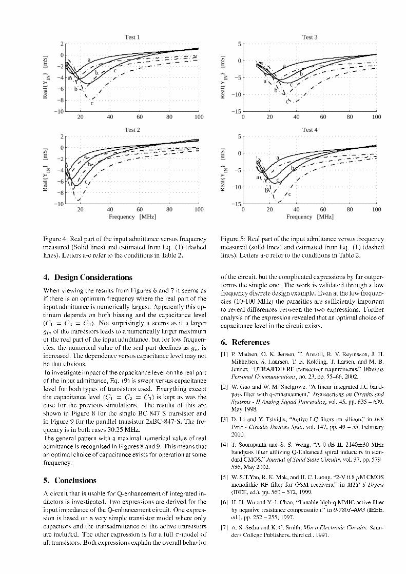
20 40 60 80 100−10
−8
−6
−4
−2
0
2R
ealY
IN
[m
S]
a
b ca
b
c
Test 1
20 40 60 80 100−10
−8
−6
−4
−2
0
2
Frequency [MHz]
Rea
lYIN
[
mS]
ab
c
Test 2
ËIz?h?gx_§ØVUw)_[aj?~eangOf9|?ÆIf 9_T d?~9hUf9avi f fÌa<d9_§?_<gbOhebAÆkgx_[Ðh9_jd9<iG_[a[bOh?gx_[vëksI|? Ìv d9_7b î a<d/v_7bOf i1a<f_[vGÆkg|iÍÐeëÒ î ëkvUa[bO9_[v d9_7b î W_jf f_<gbCat)gx_ÆS_<gVfÌ|f 9_[|d/v f Ì|debV d±^Ian/ _ÖIWÂÝÜ -/6[QONA8ÝXB58)6[QS4)-/.925Z\QSB58)6*+9_jd?_<Ç d9zµf 9_gx_7bOh9 fkbTÆkg|iÍËIz?h?gx_7bTÚ1a<d/v G fCbx__jib)a[bÆWf 9_<gx_mkba<d|7~9f ihUiâÆkgx_[Ðh9_jd9<Ç9_<gx_mf 9_gx_[ajI~eangOfA|?ÆWf 9_ d?~9hUfeavi f fÌa<d9_)kbCdUhUiG_<gO[aj ±angOzU_7bOfS9p~U~eangx_jdUf mf Ukb|7~ef ihUi v?_<~/_jd/v9b|d»e|f »9Ìa[bO d9z¹a<d/vÀf 9_[an~eajj fÌa<d9_ _<?_ëtè uÀí è ¹í èrä î |fWbOh?gS~UgOkbO d9zU 1 f§bx__jibra[b)Æ)a±angOzU_<g |?ÆIf 9_Tf ga<debOkbOfÌ|7gbA _[av9bVfÌ|a§dUhUiG_<gO[aj mangOzU_<gi1a<`U ihUi|?ÆVf 9_Tgx_[ajU~eangOfI|?Æf 9_ d?~9hUfeavi f fÌa<d9_<?hUfeÆO|7g5|7ÇFÆkgx_[Ðh9_jd/j_7b\If 9_±dUhUiG_<gO[ajA?aj h9_µ|?Ƨf 9_gx_[ajV~eangOfWv?_ d9_7bra[b kb d9<gx_[a[bx_[ve7^C9_Tv?_<~/_jd/v?_jd9_C?_<gbOhebI[an~eajj fÌa<d9_ _<?_7i1a<rd/|f/_)f /a<fI|79?Ì|hebn^I| d?_7bOf z9a<f_5 iµ~eajjf?|?Æ/f 9_[an~eajj fÌa<d9_W _<?_|drf 9_Wgx_[aj~eangOf|?ÆVf 9_r d?~9hUfIavi f fÌa<d9_ÐeAë î kb§bxÇ_<~9fI?_<gbOhebC[an~eajj fÌa<d9_ _<?_5ÆO|7gTe|f f ?~/_7b|?Ƨf ga<debOkbOfÌ|7gbhebx_[ve±W?_<gOUf U d9z1_<`9_<~9ff 9_[an~eajj fÌa<d9_± _<?_ëtè u¹í è Êí èrä î kbroU_<~9fWa[brÇa[brf 9_[a[bx_%ÆO|7gmf 9_1~Ugx_<?Ì|heb±bO ih9a<f Ì|debnÊ^C9_1gx_7bOh9 fkbµ|?Æf Ukbµangx_bO/|7Çd» dºËIz?h?gx_ ÆO|7gf 9_bO d9zU _1æ)y)/[Ø 9Ss¹f ga<debOkbOfÌ|7ga<d/v dGËIz?h?gx_GÆO|7gWf 9_~eangaj _If ga<debOkbOfÌ|7g§Ö?`Uæ)y)/[Ø 9SsA[^C9_Ækgx_[Ðh9_jd9<kbC dme|f [a[bx_7b×+I Ö9ÙÈ%$'&?^C9_zU_jd9_<gaj9~ea<f f_<gOdµÇ f 1ari1a<`U i1aj/dUhUiG_<gO[aj/?aj h9_|?ÆVgx_[ajavi f fÌa<d9_kbIgx_[|?z?dUkbx_[v) dËIz?h?gx_7b ra<d/v I?^CUkbIiG_[a<debf /a<fa<d|7~9f i1aj7j/|_|?Æ/[an~eajj fÌa<d9_W_<`UkbOfkbÆO|7g|7~/_<ga<f Ì|dra<f9b|iG_Ækgx_[Ðh9_jd9<U  XB58)9MSÅ)6[QSB58)6p j gxjhU fef /a<fIkbheban/ _ÆO|7gÔt_jdU/a<d9_jiG_jdUfe|?Æ5 dUf_jzga<f_[vm d/vh9jfÌ|7gbCkb d?_7bOf z9a<f_[veI^eÇ|µ_<`?~Ugx_7bbOÌ|debangx_mv?_<gO ?_[vÆO|7gCf 9_ d?~9hUfU iµ~/_[vUa<d9_|?ÆIf 9_Ôt_jdU/a<d9_jiG_jdUf?j gxjhU fSUÉrd9__<`?~Ugx_7bbOÌ|d1kbea[bx_[v1|dam?_<gObO iµ~/ _f ga<debOkbOfÌ|7g§i1|Uv?_Ç9_<gx_|d9 [an~eajj fÌ|7gbra<d/vf 9_µf ga<debavi f fÌa<d9_µ|?ÆTf 9_Gajjf ?_±f ga<debOkbOfÌ|7gbangx_m d9 h/v?_[ve§^C9_|f 9_<g§_<`?~Ugx_7bbOÌ|dGkb)ÆO|7gTamÆth9 ÷ ki1|Uv?_V|?Æaj ?f ga<debOkbOfÌ|7gbnæ|f m_<`?~Ugx_7bbOÌ|debI_<`?~/a< df 9_)|?_<gaj /_j/an?Ì|7g
0 20 40 60 80 100−15
−10
−5
0
5
Rea
lYIN
[
mS
]
ab
ca
b
c
Test 3
0 20 40 60 80 100−15
−10
−5
0
5
Frequency [MHz]
a
b
ca
bc
Test 4
Rea
lYIN
[
mS]
ËIz?h?gx_ÙI?w)_[aj?~eangOf9|?ÆIf 9_T d?~9hUf9avi f fÌa<d9_T?_<gbOhebVÆkgx_[Ðh9_jd9<iG_[a[bOh?gx_[vëtb|? Ìv1 d9_7b î a<d/v1_7bOf i1a<f_[v1Ækg|i Ðe±ëÒ î ëkvUa[bO9_[v d9_7b î W_jf f_<gbWatTgx_ÆS_<gVfÌ|mf 9_[|d/v f Ì|debV d^Ian/ _ÖI|?ÆIf 9_)j gxjhU ft<?hUfUf 9_)[|iµ~/ [a<f_[vr_<`?~Ugx_7bbOÌ|debI9ÆSang5|hUf ~/_<gOÆO|7gOibf 9_±bO iµ~/ _|d9_?W^C9_mÇ|7gOokbT?aj ÌvUa<f_[v±f ?g|h9z?Ga|7ÇÆkgx_[Ðh9_jd9<vkbx<gx_jf_Tv?_7bOz?d_<`/a<iµ~/ _?7W?_jda<f?f 9_§|7ÇPÆkgx_[Ðh9_jd/j_7bmëÒ9nÒ(µÈ%$'& î f 9_m~eanga[bO f 7brangx_bOh9Æ Ï j_jdUf iµ~e|7gOfÌa<dUffÌ|Ggx_<?_[aj5vÆkÆS_<gx_jd9_7bW/_jfÇ__jdf 9_fÇ|_<`?~Ugx_7bbOÌ|debnrËIh?gOf 9_<ga<d/aj ebOkbC|?ÆIf 9_)_<`?~Ugx_7bbOÌ|drgx_<?_[aj _[vrf /a<f/a<dµ|7~9f i1aj?j/|_)|?Æ[an~eajj fÌa<d9_) _<?_U d±f 9_j gxjhU f/_<`UkbOfkbnC àÀ-U]<-/.U-98)/-/6 ! "$#%'&!$(*),+ -/.0+132*45$268799:1;<-/'#=$>,
?: @9@9A1B!C58DFE;G&!$HI$ 6-/A F: J'&!C5%E;'8KL*#%98EM5N8O*&32I(QP RS*ST2IRU+ E<8V=: W98EXE=YFD9: E)Z9+1; [?\"] ^M_=` _8a;ab _=^Ma%cFd9e`$f'cFg*g"h/d] iej ] cFd9aF-/klnm9m/o9o/pq9q9k9r9r9k
k tsUuv=-w8xsUKBA J/E<-nW9/!N0(yA : n%E6: 9+ J/E<8+ =C'z|8mn;~A + 8E3X: + ZY198V=)Z9+1 [,9^Me9d9a;einj ] cFd9aQcFdf5] ^0inh9] j aIe9d9n a8j _8g*aQ06d9e` c/ ] 9d9e` b ^0c9in_8a;a8] d9FW-/A0/o/m9m9q9lFo"pxq9lF87t89
l9 S,C3:68'$&M: W9: F:1;5N0(vV+ : W9xC'z~A + 8E;v-/UM: A : Vn-/ [w: wM3b ^0c9i,5f5] ^0inh9] j a6_8n] in_8a n a8j W-/A0!%m9m,pwo9oR$89EMD%EM7k9r9r9r
&!'B-9-nE<%m89+ K8B!3B!$s-/J6N0(r1FLT0Ck$%rZlFr?>v8/mn;*~A + 8E6D9+ : A : : Jwv H398V==?0m: E<8A3: FDV+ -nE;Q: M+ 8%EvzvB$ [5=ch9^d9e`c c` ] j ej _Qf5] ^0inh9] j anW-/A0nlF=m9m=o99/poFqF87k9r9r9k
o tsU=B! &! 5882*= "88@F8X>,zX8C3D-/J/Nk 4r 63zvB)x-/-/A : + 9: V2IR~A + 8EZ.-nEuvB E=V=: W98E;; [K: U¡ ] _8a8j¢ 0H3H3Hn= £nm9m/oqF*pZo99k899
q9 >,/>,=sDZ8,' #=/z8N8&$D9%A Q9: JF1Y??Mz|V+ : W9X~A + 8E7xJ8+ : W9XE/M:1M+ 8V="Vn-/)m<8+ : -/ [": x¤¥=¦9¤F§ ¨¤9¦F§ ¢ 0H3H3H= £nm9m/k9o9k*p,k9o9o$899
(,/B!/B=/E<Q8 "nzX/B),: + ¡?] ^0i=cv` _inj ^0cFd] i*f5] ^0inh9] j a=$B8D998E;3z6-/A A J96DFA :1M8E;;/+ 9: E"= 89$n

20 40 60 80 100−8
−6
−4
−2
0
2R
ealY
IN
[m
S]
a
b c
Test 1
20 40 60 80 100−8
−6
−4
−2
0
2
Frequency [MHz]
Rea
lYIN
[
mS] a
b c
Test 2
ËIz?h?gx_)ÚIUw)_[aj?~eangOf9|?ÆIf 9_T d?~9hUf9avi f fÌa<d9_§?_<gbOhebAÆkgx_[Ðh9_jd9<iG_[a[bOh?gx_[vëtb|? Ìv1 d9_7b î a<d/v1_7bOf i1a<f_[v1Ækg|i Ðe±ë î ëkvUa[bO9_[v d9_7b î W_jf f_<gbCat)gx_ÆS_<gVfÌ|f 9_[|d/v f Ì|debV d±^Ian/ _ÖI
20 40 60 80 100−10
−5
0
5
Rea
lYIN
[
mS
]
ab
c
Test 3
20 40 60 80 100−10
−5
0
5
Frequency [MHz]
ab c
Test 4
Rea
lYIN
[
mS]
ËIz?h?gx_ Iw)_[aj9~eangOf|?ÆVf 9_r d?~9hUfIavi f fÌa<d9_r?_<gbOhebCÆS_[Ðh9_jd9<iG_[a[bOh?gx_[vëtb|? Ìv1 d9_7b î a<d/v1_7bOf i1a<f_[v1Ækg|i Ðe±ë î ëkvUa[bO9_[v d9_7b î W_jf f_<gbCat)gx_ÆS_<gVfÌ|f 9_[|d/v f Ì|debV d±^Ian/ _ÖI
0 50 100 150 200 250 300−5
−4
−3
−2
−1
0
a
b
c
Transistor: BC−847−S
Capacitance [pF]
Rea
lYIN
[
mS]
ËIz?h?gx_ /±w)_[ajW~eangOfT|?Ærf 9_G d?~9hUfTavi f fÌa<d9_G?_<gbOheb[an~eaj[ fÌa<d9_G _<?_këtè uÊí è Kí èrä î iG_[a[bOh?gx_[vë î a<d/v_7bOf i1a<f_[vÆkg|iÍÐeë î ëtb|? Ìv d9_7b î ÆO|7gWf 9_æ)y)/[Ø 9Ssf ga<debOkbOfÌ|7gOQW_jfÌf_<gbWatTgx_ÆS_<gAfÌ|f 9_[|d/v f Ì|debV d^Ian/ _ÖI
0 50 100 150 200 250 300−10
−8
−6
−4
−2
0
a
b
c
Transistor: 2xBC−847−S
Capacitance [pF]
Rea
lYIN
[
mS]
ËIz?h?gx_rw)_[aj5~eangOf|?ÆTf 9_µ d?~9hUfWavi f fÌa<d9_µ?_<gbOhebr[an~eajjÌfÌa<d9_G _<?_§ëtè uÊí è í èrä î iG_[a[bOh?gx_[vë î a<d/v_7bOf i1a<f_[vÆkg|iÕÐeAë î GW_jf f_<gbatgx_ÆS_<gAfÌ|f 9_[|d/v f Ì|debA dµ^Ian/ _ÖI îëtb|? Ìv± d9_7b î ÆO|7g5f 9_Ö?`Uæ)y)/[Ø 9Ssµf ga<debOkbOfÌ|7gOGW_jf f_<gbWatgx_ÆS_<gfÌ|mf 9_[|d/v f Ì|debV d^Ian/ _ÖI

PhD Thesis R04-1026, March 3, 2005.Texas Instruments Denmark A/S & RISC group AaU
Simulation of EVM Due to Circuit Imperfections in UMTS/FDD Transmitters
P. Madsen
The Nordic Matlab Conference 2003COMSOL, Copenhagen, Denmark, pp. 179 - 184, October 2003.
PAGE 97


!"# $%&'()* %+," - ./10324 .5*%+6 "7&*+
89;:=<?>A@CBD9FEGIHKJML)NPORQPSUTCVXWZY\[^]_Q`OaNcbcdAe^fAghOjiRelknmUVFocgFdApqYrOts
u_v^w=xKyzn|rFw=x~U=Frw xKFh ~r
c Bjt:F>Fj^ RDr\rtla RnKjRD RC l r¡ntX¢_ £ Ma \Rj C l h ¤D^¥^a Kr§¦\¨©` ^ tn K jM^ RD¡¦jª¡C«M¬I¨Pj® ¯\°M°( j±RD ²"K¥; j nr^¤" a"^ j³D\U¡Da ´\a £ ²" j_µX¡nt©¶`a t`¬R j· µ©¶M¬=¸n¦K¨©r§DlKl7D ²r^K¥M j¹µ©¶M¬? D l U ¤Dl³¥^a KrºU D¤²§Dt§ =«M¬I¨P nr^¤" ºUjn jIR »K"nKjRK^ ¤ KK¥_Dt¢¼l§»n tK ^ £ Kr tK¤ £ jR¦½¨\¾ ½ D ²r^¹^ ¤" KIt» nK¤U tKr^ ^j a½ ½¬I¿©¨©À©¿MÁM¦rÂK^ ¥nK¤Ã j¹^ ¤" Kr§l£ ÄaCR £ ²C¤tt^Rl¤Pj"D ² thK^ ¤ Kr§¦Å`ÆÈÇ Et:hÉA@ÊCFaËnÉAEÌhÍy ÎFÏͧÐÐRÎ\ÑCÒFÐjxtÍÓaÔMÎFÐKÕ?ÓÑ¡xKÎ;~\xtÍ~FÓ½ÖDÍ×w=DØFyz Ð7ÑÐz ÐjvFÙ;rÎhÒÓFRÙ¹xjÓ©uÌ×Ú"u7xKÎ;~CÛÜZÝ_Þ¹Ù;xtßhÐ_ÐRwIÐKÍÏ\Ðj~XjÝÙFÐDÓ§ÐÓÑ¡xKÎ;~\xtÍ~FÓMhÖ^ÖnÐKÍÙ\yÏhÙFÐKÍ_~\xKÑ¡x"ÍxKÑйÖDÍw=DØFyz ÐÑÐz ÐKFÙ;rÎFÐDÓÑ Ù;xKÎ(y^Ó×xtßhxKyzxtØ;z Ð=Õy Ñ ÙÑ¡\~\xKÒPà ÓßhÐKÍÓy¡rÎXÓhÖÚÞ;Üá©ÝÙFÐÎFÐKÕâÓÑ¡xKÎ;~\xtÍ~FÓXxRz¡ÓCy Î\Ñ Í\~rFÐUÎFÐKÕâÓn;ÐRy¡ãXjxKÑ y¡rÎXÓ©hÖ\Ñ ÍxKÎXÓvw3y Ñ ÑÐKÍ;ÐKͧÖDÍw=xKÎFÐhZä"ÎFÐ(ÓFRÙåÓn;ÐRy¡ãXjxKÑ y¡rÎcy^Ó×uAÍnÍDÍæÐRÑ¡DÍMÜåxRÏhÎ\y Ñ ;~hоçuæÜéèÔ;ÕÙ\yRÙ=y^Ó"x¹wIÐjxjÓhͧнÖDÍCxRz zÑ ÙFÐÑ ÍxKÎXÓw3y Ñ ÑÐKÍ_Ï\ÐRÎFÐKÍxKÑÐj~½ÐKÍnÍDÍÓÑ Ù;xKÑUxRÖ^ÖnÐRÑ©Ñ ÙFÐ×~hÐDÓy ͧÐj~ÓyÏhÎ;xRzlÝ©3w=xK\ÐÑ ÙFоÓÒXÓÑÐRw)~hÐDÓyÏhÎhÖMxÛÜZÝ_Þ7Ñ ÍxKÎXÓvw3y Ñ ÑÐKÍPy ÑFy^ÓAÎFÐÐDÓÓxtÍÒÑ¡\Î;DÕâÙ;DÕq~ryÖ^ÖnÐKͧÐRÎ\Ñ\Ry ͧR\y Ñ\y w=v;ÐKͧÖnÐRÑ y¡rÎXÓFy Î;ê;FÐRÎFÐAuæÜáÝÙFÐz y ÑÐKÍxKÑ hͧÐjrÎ\Ñ¡xKy ÎXÓFw=xKÎhÒy ÎrßhÐDÓÑ yÏFxKÑ y¡rÎXÓhÖAuæÜ6ÔhÕÙFÐKͧйÓrwIÐjrw¾ØFy ÎFÐDÓMÓ§ÐKßhÐKÍxRzÐÖ^ÖnÐRÑ^Ó¹ë§ìKí§Ô©ÕÙ\yz оrÑ ÙFÐKÍÓM\ͧÐDÓ§ÐRÎ\ÑÓy ÎFÏ\z нÐÖ^ÖnÐRÑ^Óy ÎÓn;ÐjvRy¡ãXÓÒXÓÑÐRwÓaÔtz y \Ð_RÙ;xKÎ\ÎFÐzRy w¾;ÐKͧÖnÐRÑ y¡rÎXÓPë î\íFÖDÍFÛÜZÝ_ÞDÍMFÙ;xjӧоÐKÍnÍDÍÓÖDÍ"rÑ ÙFÐKÍÓÒXÓÑÐRwÓ½ë¡ïríðÎ(xKÎ;xRz ÒXÓy^Ó"hÖÙ;DÕ'ÐjxRRÙZhÖÑ ÙFÐDÓ§Ð3XxtÍxKwIÐRÑÐKÍÓ"y Î;ê;FÐRÎFÐ3uæÜ6ÔPÕÙFÐRÎwIÐjxjÓhͧÐj~(xjÓ\ͧÐDÓ§KÍy Ø;Ðj~7y ÎcÑ ÙFÐÓn;ÐRy¡ãXjxKÑ y¡rÎXÓ3ë ñFí§ÔAÙ;xjÓÎ;rÑØ;ÐÐRÎÖr\Î;~;ÔUxKÎ;~cÓFRÙ(\Î;DÕz Ðj~hÏ\оy^ÓÎFÐÐDÓÓxtÍÒ(Ñ¡w=xK\ÐxMØh;~hÏ\ÐRÑFÖDÍAxÑ ÍxKÎXÓw3y Ñ ÑÐKÍUÖDÍPÛÜZÝ_Þ\ò¡ó©ÌÌqÙ;xKÎ;~\vÓ§ÐRÑ^ÓtðÎxKÎ;xRz ÒXÓy^ÓaÔXy ÎFz ;~ry ÎFÏ=xKÎ;xRz Ò\Ñ yjxRzPy ÎrßhÐDÓÑ yÏFxKÑ y¡rÎXÓaÔÓy w3FzxKÑ y¡rÎXÓ¾xKÎ;~cwIÐjxjÓhͧÐRwIÐRÎ\Ñ^Ó½hÖ×KÍy Ñ yjxRzÐKÍnÍDÍÓ×Ñ Ù;xKÑw3yÏhÙ\Ñ\xt\;ÐjxtÍ`y Î×xMÛÜZÝ_Þ\ò¡ó©ÌÌ6Ñ ÍxKÎXÓw3y Ñ ÑÐKÍ`y^Ó`\ͧÐDÓ§ÐRÎ\ÑÐj~ÙFÐKͧÐhôÆÃõ ËöUE>A÷Mø9FùC:\9;BD9FEa>AaËnÉAEÈ>AE@qúIû(<ÝÙFÐ3Óy w3FzxKÑ y¡rÎÓÒXÓÑÐRw*y^ÓCyz z XÓÑ ÍxKÑÐj~Iy Î7ó©yÏhhͧÐ7ìDÝÙFÐw=\~rFzxKÑ¡DÍÏ\ÐRÎFÐKÍxKÑÐDÓxÑÐDÓÑUÓyÏhÎ;xRz`xjÓCÓn;ÐRy¡ãXÐj~½ÖDÍÑÐDÓÑ^ÓhÖAÛÜZÝ_Þ\ò¡ó©ÌÌüÙ;xKÎ;~FÓ§ÐRÑ^Óë ñFíAÝÙ\y^ÓÓyÏhÎ;xRz;y^ÓMÖnÐÐj~½Ñ¡3xKÎuæÜýjxRz RFzxKÑ¡DͧÔKÕÙFÐKͧÐMy ÑFy^ÓUÑ ÙFÐ_ͧÐÖnÐKͧÐRÎFÐÖDÍ`Ñ ÙFÐuæÜjxRz RFzxKÑ y¡rÎXÓaÔAxKÎ;~ÐKþhXFÓ§Ðj~7Ñ¡cÓrwIÐ=ÐKÍnÍDÍÑ Ù;xKÑ_w=xKÒ(Ø;Ð
ÿ "!
# $ % &' (!)*&+ ( , - .*(/,01 &32*46587, 7 -06 &92*465:7,,06; &3 (< =.*7, 7 ,0!
>-? @ ?BADCEFGHIKJCL)*&'M0 # 7/,0 N.*0$7 ( ;,03 0 MOPQR!S ; =T/( 7/UV,, V -- =+ )*W-<.$.%3&--0 .1X0,Y-,0" DO ZQR!\[3 \ V.,0X-0M &.+.9 &M- ]^ &_"`! `Ma; # + (M/< b; U7 &-/K!X(c.6 # (* &- # ( 7 " &(&N7 ; M7,0$9-0V]6 &*c &7 &-/' &3- ',0! &.=.d- &+7,,' &^ ,0# (M7/9MM0 .( NK e]^&-T.+ 7 &f,00 ( 7, (M7/$.3 &BM ; M&--0 .g! S - ]^ &3 &c &^- *$KV*. ,0+-03Rgf,0 9Y !)*&.N- .,06 %;- &%V,, V .-0 g!)*&3M0 1$ .N V9(-< # &-,^-0h -/0 1iKj h^k # ( &-=3 # $ ,0%,N &67, M<# W%;-, ;--01- -0,Y-,06;=
l mn.oqp+rts=n.oqpNuwvx"n.oqp iq k
<K]^& ' & l - V 7/ c.d,0610,Y-,0^ &3- ,67, # WB;-, ;--0!)*&7, # WX;-, ;--0M # ,< 6 $]% # gy/7 $M & M 7, # z &-* 7 - "%a # 7/cR VK,| 7XiK~ k zb;-, ;--0-z; U0 ( fB- 7, UW # $q 1 2*465 .*R V V$T/7/$qR(61(]^ &%+- ~z,]^&7 &%. # $ ,03M & M 7, 1;=
mn.oqp+rts=n.oqp ,n( ~ oqpNux"n.oqpq Nn( ~ oqp i` k
>-? >-?B'6A3HG FGHIKJCL2*465V,, V .U6M/06 65)cX < -$ ,| # V KzR 9 &. # # -0 - ,0U)*W-<.$ z]^&7 &

Ñ ÒhFyjxRz z Ò¾D;ÐKÍxKÑÐDÓxKÑK;ÝÙFÐC\ÍhÐDÓÓhÖPjrÎrßhÐKÍÑ y ÎFÏÑ ÙFÐÓyÏhÎ;xRz¡ÓUÑ¡_xKÎ;~ÖlhÍÑ ÙFÐKÍ`w=xKÎ\y FFzxKÑ y¡rÎXÓUhÖ©Ñ ÙFÐÓyÏhÎ;xRzhy ÎÑ ÙFÐ7xKÎ;xRzhÏÑ ÍxKÎXÓw3y Ñ ÑÐKÍRÙ;xKy Îy Î\Ñ Í\~rFÐDÓÐKÍnÍDÍÓaÔAÐRy Ñ ÙFÐKÍÑ ÙhÍrFÏhÙ3~ry^ÓÑ¡DÍÑ y¡rÎIDÍMx~\~ry Ñ y¡rÎIhÖA\ÎFÕxKÎ\ÑÐj~¹XDÕÐKͧÔryn ÐhÎ;ry^Ó§ÐhDð½ÓÓ\w3y ÎFÏÑ Ù;xKÑhxÓyÏhÎ;xRz^Ô aÔRÐr;xRzjÑ¡ ©;z XÓxKÎ=ÐKÍnÍDÍÖl\ÎFRÑ y¡rÎ aÔ\y^ÓÖnÐj~½Ñ¡¾Ñ ÙFÐÝþ;v^ÑÐDÓÑÐKͧÔ\ÕÐw=xKÒDØFÑ¡xKy Î3ÐDÓÑ y w=xKÑÐDÓMhÖAÑ ÙFÐÐKÍnÍrÎFÐjrXÓ^òÃÓyÏhÎ;xRz¡Ó xKÎ;~ Ö^Írw(| "! $#% '&)(*+#-, çlïrè ". $#% '*/ 0+#-, çñFèvUyÖUÑ ÙFÐ×ÓyÏhÎ;xRzXy^Ó_zDÕ XxjÓÓMãXz ÑÐKͧÐj~¾xKÎ;~©|21 3"! 45". t6åy Ñ Ù798;: ~hÐRÎ;rÑ y ÎFÏxtßhÐKÍxRÏhy ÎFϹrßhÐKÍUrÎFÐMÑ y wIÐÖ^ÍxKwIÐrÔRuæÜ ç^xjÓ~hÐjã;ÎFÐj~y Îë ñFílèÔw=xKÒ¹Ø;ÐÖr\Î;~"ØFÒP|
uæÜ<>= 7?"! A@B ". A@C:7 @ @ :ED%FG%GH çIhèÌhÍy ÎFÏIxKÎ3uæÜ ÑÐDÓÑlÔFÑ ÙFÐÝþ3ÑÐDÓÑÐKÍCrÎFz Ò3\Î;DÕ×Ó1 tð¹jDÍ~ry ÎFÏ7Ñ¡âë ñFíÑ ÙFÐ3ͧÐÖnÐKͧÐRÎFÐÓyÏhÎ;xRz1 ½ÓÙ;rFz~7Ø;ÐÐDÓÑ y w=xKÑÐj~7Ö^Írw&Ñ Ù\y^Ó¹ÓyÏhÎ;xRzlIÝÙFоÜZðÝKJðML ÓÒXÓÑÐRwýy^ÓÓy w¾;z y¡ãXÐj~"jrw¾XxtͧÐj~CÑ¡"Ñ Ù\y^Ót1 Py^Ó`Ñ¡xK\ÐRÎ×~ry ͧÐRÑz ÒÖ^ÍrwÑ ÙFÐw=\~rFzxKÑ¡DÍxKÎ;~3jrw¾XxtͧÐj~¹Ñ¡N1 t4nÑ`y^ÓMy w¾XDÍÑ¡xKÎ\ÑÑ Ù;xKÑ©Ñ ÙFÐ"FÙ;xjÓ§ÐxKÎ;~½Ñ y wIÐ×ÓÒ\ÎFRÙhÍrÎ\yPOjxKÑ y¡rιy^Ó_w=xKy Î\Ñ¡xKy ÎFÐj~Ø;ÐRÑÕÐÐRÎ¹Ñ ÙFÐCÑÕ¾ÓyÏhÎ;xRz¡ÓtuæÜ)y^ÓUjxRz RFzxKÑÐj~"Ö^ÍrwÃrÎFÐÓxKw¾;z ÐChÖ©ÐKßhÐKÍÒRÙ\y P-LCÐjvÖDͧÐAuæÜ!y^Ó©jxRz RFzxKÑÐj~;ÔØXrÑ ÙQ1 PxKÎ;~R1 PxtͧÐ_ãXz ÑÐKͧÐj~Õy Ñ ÙÑ ÙFÐ3FFz¡Ó§ÐÓÙ;xtFy ÎFÏãXz ÑÐKÍ3ë ñFíÝÙ\y^ÓÙ;xjÓÑ ÙFÐ=ÐÖ^ÖnÐRÑÑ Ù;xKÑ;rÎFz Òy Î;v¡ØXxKÎ;~"ÐKÍnÍDÍPjrÎ\Ñ Íy Øh\Ñ y¡rÎXÓPhÖPxtͧÐy ÎFz ;~hÐj~y ÎuæÜájó©hÍÑ ÙFÐKÍw=DͧÐrÔjÖ^ͧÐrFÐRÎFKÒhÔRÑ y w3y ÎFÏXÔjFÙ;xjÓ§ÐxKÎ;~¾xKw=v;z y Ñ ;~hйhÖÑ ÙFоÓyÏhÎ;xRz¡Ó_w=xKÒ3Ø;Ð×x~TS§XÓÑÐj~=Ó3Ñ ÙFнÓw=xRz z ÐDÓÑXFÓÓy Ø;z ÐCuæÜýy^ÓDØFÑ¡xKy ÎFÐj~XÝÙFÐÜZðÝKJðMLZÓy w3FzxKÑ y¡rÎÑ¡\hzjXÓ§ÐDÓ`xÑ Íy¡xRzrxKÎ;~ÐKÍnÍDÍ©xtXv\Í\xRRٽѡ½w=xK\Ð"Ñ ÙFÐ"Ñ y wIйx~TS§XÓÑ wIÐRÎ\Ñ^Ót`ÝÙ\y^Óy^Ó~\rÎFÐCØFÒÓÙ\yÖlÑ y ÎFÏÑ ÙFÐÓxKw¾;z y ÎFÏCÑ y wIÐhÖ1 `y Îjrw¾XxtÍy^ÓrÎÕy Ñ Ù1 aÔDxKÎ;~"Ñ ÙFÐRιjxRz RFzxKÑÐMuæÜáKÝÙ\y^ÓPwIÐjxKÎXÓ`Ñ Ù;xKÑ\Ñ ÙFÐMͧÐDÓvhz \Ñ y¡rÎ7ÖDÍÑ y wIÐIhÖ^Ö§Ó§ÐRÑ^Ó"~hÐK;ÐRÎ;~FÓCrÎ7Ñ ÙFÐIÓxKw¾;z y ÎFÏÖ^ͧÐjvrFÐRÎFKÒ\Xó`DÍÐjxRRÙ¾ÑÐDÓÑÐj~×Ñ y wIйhÖ^Ö§Ó§ÐRÑXÑ ÙFйÓyÏhÎ;xRz;y^Ó~\DÕÎÓxKw¾;z Ðj~Ñ¡rÎFÐ=ÓxKw¾;z о;ÐKÍRÙ\y ZxKÎ;~x~TS§XÓÑ wIÐRÎ\Ñ^ÓxtͧÐw=x~hÐ(ÓcÑ Ù;xKÑQ1 3xKÎ;~U1% ½Ù;xjÓ×Ñ ÙFÐÓxKwIÐ(xtßhÐKÍxRÏ\Ðj~FÙ;xjÓ§ÐrÔjxKÎ;~MV\rÑFÜéÐjxKξÞ2r;xtͧÐxKw¾;z y Ñ ;~hÐhWÆÈÇ"X ùC9;:%YK9;FaËnÉAECB¾TZ>A[â9FEC9;:F>At97úIû(<ÝÙ\y^Ó`Ó§ÐRÑ y¡rÎy ÎrßhÐDÓÑ yÏFxKÑÐDÓX~ryÖ^ÖnÐKͧÐRÎ\ÑjRy ͧR\y Ñy w¾;ÐKͧÖnÐRÑ y¡rÎXÓKà ÓÐÖ^ÖnÐRÑ^ÓMrÎ3uæÜárðÃÑ ÒhFyjxRz`xt\\Í\xRRٽѡ¾hXvljrÎrßhÐKÍÓy¡rÎy νÛÜZÝ_Þ3Ñ ÍxKÎXÓw3y Ñ ÑÐKÍÓUy^Óyz z XÓÑ ÍxKÑÐj~y νó©yÏhhͧÐî©nÑ©xRz¡Óyz z XÓÑ ÍxKÑÐDÓ3w=FÓÑhÖ×Ñ ÙFÐcRy ͧR\y Ñ"y w¾;ÐKͧÖnÐRÑ y¡rÎXÓ×Ñ Ù;xKѹxtͧÐjrÎXÓy¡~hÐKͧÐj~"y Î½Ñ Ù\y^ÓPXxt;ÐKÍ\] ^-]`_+a+bdcegf'h iPjkml2noqp+psrnjÖ;Ñ ÙFÐR^ò6ÓyÏhÎ;xRz¡ÓUxtͧÐMjrÎrßhÐKÍÑÐj~Ñ¡MAÕy Ñ Ù¹~ryÖ^ÖnÐKͧÐRÎ\ÑhxKw=v;z y Ñ ;~hÐ3ÕÐRyÏhÙ\Ñ^ÓaÔPÑ ÙFÐ=~ryÖ^ÖnÐKͧÐRÎFнy ÎÕÐRyÏhÙ\Ñw=xKÒ7Ø;ÐIÐKþ;v\ͧÐDÓÓ§Ðj~ØFÒqtüxKÎ;~q Aw=xKÒ¹Ø;ÐÐKþh\ͧÐDÓÓ§Ðj~"ØFÒP| uvt '&)(*+#-, K '*/ 0+#-, 5çwhè
ó©yÏhhͧÐî`|U\Íy ÎFRy XxRz;hXvljrÎrßhÐKÍÓy¡rξxt\\Í\xRRÙ¾y ÎIÛÜZÝ_ÞÑ ÍxKÎXÓw3y Ñ ÑÐKÍÓAÕy Ñ Ù3ÓrhͧÐDÓhÖ`uæÜýy Î;~ryjxKÑÐj~XÝÙFÐ=jrw¾;z ÐKþ7ØXxjÓ§ÐKØXxKÎ;~ͧÐK\ͧÐDÓ§ÐRÎ\Ñ¡xKÑ y¡rÎy^Ó×DØFÑ¡xKy ÎFÐj~=ØFÒ~\DÕÎ;vljrÎrßhÐKÍÓy¡rÎxjÓ~hÐDÓ§KÍy Ø;Ðj~y ξÞXÐRÑ y¡rνî`|1 u9t x5 çzy\èÝÙ\y^ÓXÑ ÍxKÎXÓw3y Ñ ÑÐKÍ;ÐKÍnÍDÍ;Öl\ÎFRÑ y¡rÎCy^ÓXy w¾;z ÐRwIÐRÎ\ÑÐj~_y Î"ÜZðÝXvJðMLÝÙFÐ_xKw¾;z y Ñ ;~hÐhÖ^Ö§Ó§ÐRÑR\Í\~rFÐDÓ;ÐKÍnÍDÍÓFy ÎØXrÑ ÙFÙ;xjÓ§ÐxKÎ;~XDÕÐKÍnÑ"xt\;ÐjxtÍÓ×Ñ Ù;xKÑCÑ ÙFÐxKw¾;z y Ñ ;~hÐ7ÐKÍnÍDÍÓ½xtͧÐw=FÓÑCÓyÏhÎ\y¡ãXjxKÎ\Ñnð×~TS§XÓÑ y ÎFÏ(ÖDÍÐr;xRz_xtßhÐKÍxRÏ\оXDÕÐKÍxKÎ;~×xjÓÓ\w3y ÎFÏÑ Ù;xKÑ|7 A@C:q7 A@C:½ÔDxKξxKÎ;xRz Ò\Ñ y¡vjxRz;ÐDÓÑ y w=xKÑÐ"hÖ`uæÜýw=xKÒ¹Ø;ÐÖr\Î;~"ØFÒP|
uæÜ ð>~ #qd #t @ F t? F DFG%GH
ç+DèÝÙFÐMÐÖ^ÖnÐRÑDy^Ó`wIÐjxjÓhͧÐj~CXÓy ÎFÏxCÓy w¾;z ÐCÓ§ÐRÑ hÕÙFÐKͧРxKÎ;~ CxtͧÐ×jrÎrßhÐKÍÑÐj~½Ñ¡=xKÎ;xRzhÏ=xKÎ;~3ÖnÐÐj~=~ry ͧÐRÑz ÒIÑ¡xKÎ=ðÎhÍy Ñ^Ó=ÜåÞU-w%hðÃÝþ;v^ÑÐDÓÑÐKÍÝÙFоӧÐRÑ h7Ï\ÐRÎFÐKÍxKÑÐDÓxKÎ=uæÜhÖMxtØXr\ÑPîó©yÏhhͧоï=ÓÙ;DÕ×ÓMuæÜ ð unÑPy^Ó
−1.5 −1 −0.5 0 0.5 1 1.50
1
2
3
4
5
6
7
8
9
I/Q amplitude offset [dB]
EV
MA [%
]
ó©yÏhhͧнïX|MÞ©hz y¡~Iz y ÎFÐDÓCxtͧоÓy w3FzxKÑÐj~3ßhxRz FÐDÓaÔ;Ry ͧz ÐDÓCxtͧÐÐDÓÑ y w=xKÑÐj~¹Ö^ÍrwÃu4X'xKÎ;~×~\rÑ^ÓxtͧÐCwIÐjxjÓhͧÐj~ßhxRz FÐDÓtÓ§ÐÐRÎIÑ Ù;xKÑXØXrÑ Ù3Ñ ÙFÐÜZðÝKJðML Óy w3FzxKÑ y¡rÎXÓMxKÎ;~½Ñ ÙFÐ×xKÎ;xvz Ò\Ñ yjxRzXxt\\Írþ\y w=xKÑ y¡rÎy Î×u4X'ÐDÓÑ y w=xKÑÐCuæÜ ÕÐz zl\] ]g_+a+b?Km%rnoqp+psrnjÝÙFÐKͧÐ×w=xKÒØ;Ð3xKÎ(hÖ^Ö§Ó§ÐRÑUy Î7Ñ ÙFÐ×FÙ;xjÓ§Ð3hÖ_Ñ ÙFÐq^òÃXxtÍÑ^ÓtÝÙ\y^ÓPw=xKÒØ;Ð_ͧÐK\ͧÐDÓ§ÐRÎ\ÑÐj~CØFÒ×xFÙ;xjÓ§ÐChÖ^Ö§Ó§ÐRÑhy Î¹Ñ ÙFÐÓy ÎFÏ\z Ð

Ñ¡rÎFÐÓyÏhÎ;xRz¡ÓPÑ Ù;xKÑ;xtͧÐXÓ§Ðj~"Ñ¡hXvljrÎrßhÐKÍÑDÑ ÙFÐ"ÓyÏhÎ;xRzlrÝÙFÐhXvljrÎrßhÐKÍÑÐj~ÓyÏhÎ;xRz\w=xKÒ¹Ø;ÐÐKþh\ͧÐDÓÓ§Ðj~"ØFÒP| '&)(* #-,A # çz\è '*/ 0 #-,A4 #6áÙFÐRÎ1 `y^ÓU~\DÕÎ;vljrÎrßhÐKÍÑÐj~xjÓU~hÐDÓ§KÍy Ø;Ðj~Cy ιÞXÐRÑ y¡rÎîXÔÑ ÙFÐjrw¾;z ÐKþØXxjÓ§ÐKØXxKÎ;~¹ÓyÏhÎ;xRzhØ;ÐjrwIÐDÓK|
1 '&)(* # '*/ 0 # çì \è5 '*/ 0 # '&)(* #ðξxKÎ;xRz Ò\Ñ yjxRz\ÐKþh\ͧÐDÓÓy¡rÎ×ÖDÍPuæÜ?w=xKÒØ;ÐÖr\Î;~Ö^Írwu4Xì ©¹xtßhy ÎFϽxt\;z yÐj~×xFÙ;xjÓ§ÐÓÙ\yÖlÑ©hÖ @ Ñ¡¹Ñ ÙFÐu^òjxtÍnÍyÐKÍÓy ÎXÓÑÐjx~3hÖ xKÑUrÎFz ÒIrÎFÐjxtÍnÍyÐKͧÔDÎ;×FÙ;xjӧйhÖ^ÖvÓ§ÐRÑUÓÙ;rFz~Ø;Ð"ÎFÐÐDÓÓxtÍÒ½y Î¾Ñ ÙFÐ"uæÜ jxRz RFzxKÑ y¡rÎXÓt©ÝÙFÐÐKþh\ͧÐDÓÓy¡rÎXÓPjrÎ\Ñ¡xKy Î¹Ñ ÙFÐ"xtßhÐKÍxRÏ\ÐhÖ©\Í\~rFRÑ^ÓUhÖmçÑèPxKÎ;~×çÑèÔ`Øh\Ñ_yÖÑ ÙFÐKÒcxtͧÐ3w3\Ñ ;xRz z Ò\ÎFjDÍnͧÐzxKÑÐj~;Ô`Ñ ÙFÐ=xtßhÐKÍvxRÏ\Ð=hÖÑ ÙFо\Í\~rFRÑ^Óy^ÓMOÐKÍX=ÝÙFнFÙ;xjÓ§Ð=hÖ^Ö§Ó§ÐRÑ^ÓjxKXÓ§ÐRÙ;xKÎFÏ\ÐDÓ¹y ÎâxKw¾;z y Ñ ;~hÐhâÛ½Óy ÎFÏZÑ ÙFÐ(DFÑ y w=xRzCxKw¾;z y Ñ ;~hÐͧÐRÏhFzxKÑ y¡rΩÔKuæÜýw=xKÒ¹Ø;ÐÖr\Î;~xKÎ;xRz Ò\Ñ yjxRz z ÒØFÒP|uæÜ F &)(* # @ DFG%GH çì\ìKè
nÎ=\ÍxRRÑ yÐ½Ñ ÙFоxKw¾;z y Ñ ;~hоx~TS§XÓÑ wIÐRÎ\Ñ^ÓrÎFz Ò7jxKXӧнw3y¡vÎ;DÍCy w¾\ÍrßhÐRwIÐRÎ\Ñ^ÓMy ÎuæÜ 3ÝÙFоÜZðÝKJðML Óy w=vFzxKÑ y¡rÎchÖCÑ ÙFÐIÑ ÍxKÎXÓw3y Ñ ÑÐKÍÐKÍnÍDÍÖl\ÎFRÑ y¡rÎXÓ"y w¾;z ÐRwIÐRÎ\Ñ^Óu4X ì ©cÜéÐjxjÓXÓnͧÐRwIÐRÎ\Ñ^Ó¹xtͧÐjrÎ;~rFRÑÐj~7XÓy ÎFÏZx vuñ\ñXï\ï"L6ÓyÏhÎ;xRzXÏ\ÐRÎFÐKÍxKÑ¡DÍPÑ¡×hXvljrÎrßhÐKÍÑhÑ ÙFÐB^òÈÓyÏhÎ;xRz¡ÓÑ¡éìD IÚMOrÔ`ÕÙ\yRÙÑ ÙFÐRÎy^Ó"ÖnÐj~=Ñ¡=Ñ ÙFнÝþ;v^ÑÐDÓÑÐK͹ÝÙFÐFÙ;xjÓ§Ð~ryÖ^ÖnÐKͧÐRÎFÐy^ÓMÏ\ÐRÎFÐKÍxKÑÐj~¹XÓy ÎFÏ3xØh\yz Ñ¡v^y Î3Öl\ÎFRÑ y¡rÎy Î v^uñ\ñXï\ï"LAÝÙFÐ(uæÜhÖ×Ñ ÙFÐéÓ§ÐRÑ h6y^Ó=xt\\ÍrþâîquæÜ y^ÓIÓÙ;DÕÎZy Îéó©yÏhhͧÐñ`áÝÙFÐ7wIÐjxjÓhͧÐj~
−10 −5 0 5 100
1
2
3
4
5
6
7
8
9
I/Q phase offset [deg.]
EV
MP
IQ [%
]
ó©yÏhhͧÐñP|MÞ©hz y¡~Iz y ÎFÐDÓCxtͧоÓy w3FzxKÑÐj~3ßhxRz FÐDÓaÔ;Ry ͧz ÐDÓCxtͧÐÐDÓÑ y w=xKÑÐj~¹Ö^ÍrwÃu4ì\ìCxKÎ;~¹~\rÑ^ÓxtͧÐCwIÐjxjÓhͧÐj~ßhxRz FÐDÓtuæÜ ÑÐRÎ;~FÓ"Ñ¡Ø;Ð=Ów=xRz z ÐKÍ"Ñ Ù;xKÎcÓy w3FzxKÑÐj~xKÎ;~7ÐDÓvÑ y w=xKÑÐj~X¹DÕÐKßhÐKÍXÑ ÙFÐC~ryÖ^ÖnÐKͧÐRÎFÐy^ÓÓ×Ów=xRz zrÑ Ù;xKÑhy Ñ\w=xKÒØ;Ð=ÐKþh;zxKy ÎFÐj~=ØFÒ(Ñ¡hz ÐKÍxKÎFÐDÓ"y ÎÑ ÙFÐ3FÙ;xjÓ§Ð=hÖ^Ö§Ó§ÐRÑ_y ÎÑ ÙFÐÓyÏhÎ;xRzFÏ\ÐRÎFÐKÍxKÑ¡DÍ
\] \]`Km%rniPrnÝÙFÐjxtÍnÍyÐKÍÓaÔͧÐK\ͧÐDÓ§ÐRÎ\ÑÐj~ØFÒ&)(*+#-,A PxKÎ;~Q*/ 0+#-, aÔw=xKÒ½Ø;Ð"jrßhÐKͧÐj~¹Õy Ñ Ù½FÙ;xjÓ§Ð"Î;ry^Ó§Ðh×DÍw=xRz z Ò½Ñ ÙFÐjxtÍnÍy¡vÐKÍÓ×xtͧÐ7DÍyÏhy Î;xKÑÐj~Ö^Írw?Ñ ÙFÐÓxKwIÐÓrhͧÐhÝÙFÐ3FÙ;xjÓ§ÐÎ;ry^Ó§ÐCy Î½Ñ ÙFÐjxtÍnÍyÐKÍÓUw=xKÒ×Ñ ÙFÐKͧÐÖDͧÐ_Ø;Ð"~hÐDÓ§KÍy Ø;Ðj~"ØFÒ×Ñ ÙFÐÓxKwIÐ_Î;ry^Ó§Ð_Öl\ÎFRÑ y¡rÎ4 UxjÓ©yz z XÓÑ ÍxKÑÐj~Cy Îó©yÏhhͧÐ_î©DÝÙFÐͧÐDÓFz Ñ y ÎFϹhXvljrÎrßhÐKÍÑÐj~ÓyÏhÎ;xRz^Ô- aÔØ;ÐjrwIÐDÓK| '&)(*+#-,K4 çìKî\è '*/ 0+#-,K4 ÝÙFÐ"~\DÕÎ×jrÎrßhÐKÍÑÐj~"jrw¾;z ÐKþØXxjÓ§ÐKØXxKÎ;~ͧÐK\ͧÐDÓ§ÐRÎ\Ñ¡xKÑ y¡rÎy^ÓÖr\Î;~Ñ¡Ø;Ð\|1 '&)(*4 4 '*/ 04 çìïrè5A '*/ 04 4 '&)(*4 ¹xtßhy ÎFϹxt\;z yÐj~Ñ ÙFÐÓxKwIÐMFÙ;xjÓ§ÐCÓÙ\yÖlÑ\Ñ¡BUxKÎ;~×ÔRÑ ÙFÐCxtßFvÐKÍxRÏ\ÐXDÕÐKÍAy^ÓÎ;rÑ©RÙ;xKÎFÏ\Ðj~X©ð½ÓÓ\w3y ÎFÏ×Ñ Ù;xKÑK74 q:y^Ó2OÐKÍ;ÔKxjrÎXÓÑ¡xKÎ\ÑFÙ;xjÓ§Ð_hÖ^Ö§Ó§ÐRÑjÕyz zjÎ;rÑjw3y Î\y w3yPOÐuæÜ6ÔxKÎ;~¾xKÎIxKÎ;xRz Ò\Ñ yjxRz;ÐKþh\ͧÐDÓÓy¡rξÖDÍAuæÜ6ÔFç^xjÓÓ\w3y ÎFÏ×Ñ Ù;xKÑçÑèXxKÎ;~B×çÑèXxtͧÐ_w3\Ñ ;xRz z Ò\ÎFjDÍnͧÐzxKÑÐj~hèhjxKÎØ;Ð~hÐKÍy ßhÐj~©|uæÜ ! #q#7d&)(*4 M: DFG%GH çìtñFè
ó`DÍMxMOÐKͽwIÐjxKνFÙ;xjÓ§ÐÎ;ry^ӧйÖl\ÎFRÑ y¡rÎ"4 Õy Ñ Ù7Ów=xRz z;ÐjxK"Ñ¡"xtßhÐKÍxRÏ\Ð_ßhxRz FÐDÓaÔ"7d&)(*4 M:éw=xKÒØ;ÐMxt\\Írþ;vy w=xKÑÐj~ØFÒ½Ñ ÙFÐ"jFÓy ÎFÐhÖPÑ ÙFÐuV\rÑXÜéÐjxKξÞ2r;xtͧйçPVÜåÞXèßhxRz FÐ_hÖ4 aÔRÕÙ\yRÙy^ÓXÎ;DÍw=xRz z ÒÓn;ÐRy¡ãXÐj~XDÛÎ;~hÐKÍ;Ñ ÙFÐDÓ§ÐRy ͧR\wÓÑ¡xKÎFÐDÓPu4XUìtñ×w=xKÒ¹Ø;ÐÐKþh\ͧÐDÓÓ§Ðj~"ØFÒP|uæÜ #q##%$| D%FG%GH çì)Ihè
vÕÙFÐKͧÐ&y^ÓMÑ ÙFÐVÜåÞ(hÖ'4 tu4X×ì)I¾y^ÓCÐr;xRz©Ñ¡IÐKþ;v\ͧÐDÓÓy¡rÎIì\ìAy Î3ë¡ïríru4X`ìïy^Ó`y w¾;z ÐRwIÐRÎ\ÑÐj~My ÎÜZðÝKJðMLXÓy ÎFÏÍxKÎ;~\rwqFÙ;xjÓ§Ð_Î;ry^Ó§ÐMÖDÍ4 t\ÝÙFÐDØFÑ¡xKy ÎFÐj~CÎ;ry^Ó§ÐÓn;ÐRÑ Í\wüy^Óê©xKÑXxKÎ;~ÏFhÐDÓUÖ^ÍrwüÌ(ZÑ¡Ñ ÙFÐÓxKw¾;z y ÎFÏÖ^ͧÐjvrFÐRÎFKÒhÔhØh\Ñ~rFйѡIÑ ÙFоãXz ÑÐKÍy ÎFÏIy ÎÑ ÙFÐ×uæÜ wIÐjxjÓhͧÐjvwIÐRÎ\ÑlÔDrÎFz Ò¹y Î;v¡ØXxKÎ;~FÙ;xjÓ§ÐÎ;ry^Ó§Ð"x~\~FÓUÑ¡uæÜ \ÝÙ\y^Óy^Ó"jrw¾;ÐRÎXÓxKÑÐj~¾ØFÒw3Fz Ñ y ;z Ò\y ÎFÏIÑ ÙFÐ×FÙ;xjӧнÖl\ÎFRÑ y¡rÎIØFÒÑ ÙFÐÓAr;xtͧÐhÖÑ ÙFÐ(rßhÐKÍvÓxKw¾;z y ÎFÏÍxKÑ y¡X6ÌhÍy ÎFÏwIÐjxvÓhͧÐRwIÐRÎ\Ñ^ÓÑ ÙFÐ^ò ÓyÏhÎ;xRz¡ÓxtͧнÖnÐj~IÑ¡IÑ ÙFÐ3ÓyÏhÎ;xRzUÏ\ÐRÎFÐKÍvxKÑ¡DÍ"ÕÙ\yRÙjrÎrßhÐKÍÑ^ÓÑ ÙFÐIÓyÏhÎ;xRzAÑ¡åìD IÚMOIxKÎ;~7x~\~FÓÎ;ry^Ó§ÐhhÝÙFÐ VÜåÞ3Î;ry^Ó§ÐCÐKÍnÍDÍPy^ÓPͧÐjx~Ö^ÍrwÃÑ ÙFÐCÝþ;v^ÑÐDÓÑÐKÍuæÜ y^Ó=ÓÙ;DÕÎéy Îåó©yÏhhͧРIXÃÚ\\~éxRÏrͧÐÐRwIÐRÎ\Ñy^ÓxRRÙ\yÐKßhÐj~Ø;ÐRÑÕÐÐRιwIÐjxjÓhͧÐj~;ÔKÑ ÙFÐjDͧÐRÑ yjxRzFxKÎ;~×Óy w3FzxKÑÐj~ͧÐDÓFz Ñ^Ót\] )]g_egf2n+*)psn+,j.-*)n0/kmn+12,%354Mnrf2612rnÝÙFÐCRy ͧR\y Ñ^ÓPy Î¹Ñ ÙFÐÑ ÍxKÎXÓw3y Ñ ÑÐKÍ`w=xKÒ×RÙ;xKÎFÏ\ÐMRÙ;xtÍxRRÑÐKÍy^ÓvÑ yDÓCÓyÏhÎ\y¡ãXjxKÎ\Ñz Ò3rßhÐKÍÖ^ͧÐrFÐRÎFKÒ\XÝÙ\y^ÓwIÐjxKÎXÓÑ Ù;xKÑ`xKw=v;z y Ñ ;~hÐ=xKÎ;~FÙ;xjÓ§Ð3ͧÐDÓnXrÎXÓ§Ð3w=xKÒRÙ;xKÎFÏ\Ð3ÖD͹~ryÖ^ÖnÐKͧÐRÎ\ÑXxtÍÑ^ÓChÖÑ ÙFнÓyÏhÎ;xRzPxjÓyz z XÓÑ ÍxKÑÐj~¾y ÎIó©yÏhhͧÐwX'ÐKͧÐÑ ÙFÐw=xRÏhÎ\y Ñ ;~hÐhÖFÑ ÙFÐͧÐDÓnXrÎXÓ§ÐRÙ;xKÎFÏ\ÐDÓFØFÒMt57rßhÐKÍ;Ñ ÙFÐÓyÏFvÎ;xRznà ÓØXxKÎ;~hÕy¡~rÑ Ù©ÔUÕÙ\yRÙwIÐjxKÎXÓÑ Ù;xKÑ~ryÖ^ÖnÐKͧÐRÎ\ÑXxtÍÑ^Ó¹hÖÑ ÙFÐ×ÓyÏhÎ;xRzXÕyz zXØ;ÐÐKþhXFÓ§Ðj~¹Ñ¡3~ryÖ^ÖnÐKͧÐRÎ\ÑXÏFxKy Î`mÖUÑ ÙFÐRy ÍvR\y Ñ;Ù;xjÓ_xjrÎXÓÑ¡xKÎ\Ñ;ÏrÍrh¾~hÐzxKÒ¾ÖDÍxRz zXÖ^ͧÐrFÐRÎFRyÐDÓaÔRÑ ÙFÐFÙ;xjӧнÓÙ;rFz~3~hÐK;ÐRÎ;~3rÎIÖ^ͧÐrFÐRÎFKÒ¾y Îx¹z y ÎFÐjxtÍw=xKÎ\ÎFÐKÍ

0 1 2 3 4 50
1
2
3
4
5
6
7
8
9
RMS phase noise [deg.]
EV
MP
N [%
]
ó©yÏhhͧÐI©|MÞ©hz y¡~Iz y ÎFÐDÓCxtͧоÓy w3FzxKÑÐj~3ßhxRz FÐDÓaÔ;Ry ͧz ÐDÓCxtͧÐÐDÓÑ y w=xKÑÐj~¹Ö^ÍrwÃu4ì)I×xKÎ;~¹~\rÑ^ÓxtͧÐCwIÐjxjÓhͧÐj~ßhxRz FÐDÓt
ó©yÏhhͧÐgw©|Cz z XÓÑ ÍxKÑ y¡rÎZhÖÖ^ͧÐrFÐRÎFKÒ7ͧÐDÓnXrÎXÓ§ÐDÓtâÞ©hz y¡~z y ÎFÐDÓͧÐK\ͧÐDÓ§ÐRÎ\Ñx×Î;rÎ;v^y¡~hÐjxRz©Í§ÐDÓnXrÎXӧоxKÎ;~~\xjÓÙFÐj~=z y ÎFÐDÓxKÎ×y¡~hÐjxRzhͧÐDÓnXrÎXÓ§Ðh
xjÓAyz z XÓÑ ÍxKÑÐj~ØFÒ×Ñ ÙFÐ~\xjÓÙFÐj~¹z y ÎFÐh%Ö`Ñ Ù\y^ÓAy^ÓÎ;rÑFÑ ÙFÐjxjÓ§ÐrÔÖlhÍÑ ÙFÐKÍUÐKÍnÍDÍÓUÕyz z\Ø;Ð"x~\~hÐj~Ñ¡Ñ ÙFÐÓyÏhÎ;xRzló©yz ÑÐKÍÓÕy Ñ Ù7x¹Î;xtÍnÍDÕ ØXxKÎ;~hÕy¡~rÑ ÙIjrw¾XxtͧÐj~½Ñ¡3Ñ ÙFоÓyÏFvÎ;xRzXxtͧÐÏF\\~¹ÐKþ;xKw¾;z ÐDÓAhÖURy ͧR\y Ñ^ÓAÕÙFÐKͧÐCÎ;rÎ;v^y¡~hÐjxRz\Ö^ͧÐjvrFÐRÎFKÒͧÐDÓnXrÎXÓ§ÐDÓw=xKÒjxKXÓ§Ð=ÓyÏhÎ\y¡ãXjxKÎ\ÑuæÜáXuæÜ~rFÐCÑ¡y w¾;ÐKͧÖnÐRÑ;ãXz ÑÐKÍy ÎFÏw=xKÒ¹Ø;ÐÐKþh\ͧÐDÓÓ§Ðj~"ØFÒë î\í|uæÜ ó `t 90 Q D%FG%GH çì)whè
ÕÙFÐKͧÐ`t6y^ÓÑ ÙFÐMVÜåÞw=xRÏhÎ\y Ñ ;~hÐÐKÍnÍDÍÑ¡3Ñ ÙFÐVÜåÞw=xRÏhÎ\y Ñ ;~hÐy Î¾Ñ ÙFÐCØXxKÎ;~¾çty νó©yÏhhͧÐwhèÔDxKÎ;~ y^ÓCÑ ÙFÐqVÜåÞFÙ;xjӧнÐKÍnÍDͧÔ;jrw¾XxtͧÐj~¾Ñ¡=Ñ ÙFйFÙ;xjӧнÖl\ÎFjvÑ y¡rÎ¾Ñ Ù;xKÑ©Ï\ÐRÎFÐKÍxKÑÐDÓAÑ ÙFйÓw=xRz z ÐDÓÑ2VÜåÞIFÙ;xjÓ§Ð"ÐKÍnÍDÍ©ÝÙFÐVÜåÞ7ßhxRz FÐDÓ_xtͧйrÎFz Ò3Ñ¡×Ø;ÐjxRz RFzxKÑÐj~½Õy Ñ Ù\y Î3Ñ ÙFÐ"ØXxKÎ;~hRhFyÐj~ØFÒ×Ñ ÙFÐÓyÏhÎ;xRzlÖx×jrw¾;z ÐKþÖ^ͧÐrFÐRÎFKҾͧÐDÓnXrÎXӧнhÖx¾ãXz ÑÐKÍy^ÓC\Î;DÕΩÔu4Xì)w×w=xKÒ½Ø;ÐXÓ§Ðj~×Ñ¡¾ÐDÓÑ y w=xKÑÐ"uæÜáDÝ©×ÑÐDÓÑ`Ñ Ù\y^ÓÑ ÙFÐͧÐDÓnXrÎXӧйhÖMxØXxKÎ;~×XxjÓÓCãXz ÑÐKÍÕy Ñ Ù7x¹ÐRÎ\Ñ Í§ÐÖ^ͧÐrFÐRÎFKÒhÖï"IÜ MO½ÕxjÓCwIÐjxjÓhͧÐj~3XÓy ÎFÏxKÎÞ©v¡XxtÍxKwIÐRÑÐKÍ_ÑÐDÓÑÓ§ÐRÑnð ÜZðÝKJðMLâÍr\Ñ y ÎFÐÑ Ù;xKÑU~hÐKÍy ßhÐDÓ`táxKÎ;~ Ö^ÍrwüÑ ÙFÐCwIÐjxjÓhͧÐj~ @ ßhxRz FÐDÓPy^ÓAw=x~hÐhrðÎ;rÑ ÙFÐKÍ`ÜZðÝXvJðML(Ír\Ñ y ÎFÐÑ Ù;xKÑFÓy w3FzxKÑÐDÓXÑ ÙFÐãXz ÑÐKÍ©XÓy ÎFÏxw=\~rFzxKÑÐj~ÓyÏhÎ;xRzhy^ÓxRz¡Ów=x~hÐhrðqÖnÐKÕ6y w¾XDÍÑ¡xKÎ\ÑrÎ;rÑÐDÓArÎ¹Ñ ÙFÐÓy w=vFzxKÑ y¡rÎXÓMxtͧÐ"\ͧÐDÓ§ÐRÎ\ÑÐj~×ÙFÐKͧÐ\|èÝÙFйãXz ÑÐKÍy ÎFϾy^Ó~\rÎFÐ"y ÎÑ ÙFÐÖ^ͧÐrFÐRÎFKÒ¹~\rw=xKy Î`DÝÙFÐ"ÓyÏhÎ;xRz\y^ÓUͧÐK\ͧÐDÓ§ÐRÎ\ÑÐj~"y Î×y Ñà ÓhXvljrÎrßhÐKÍÑÐj~MÖDÍw7Ôtyn ÐCxjÓ`Ñ ÙFÐMó`rhÍyÐKÍXÑ ÍxKÎXÓ§ÖDÍwühÖm t+èÝÙFÐ×wIÐjxjÓhͧÐj~=ãXz ÑÐKÍMͧÐDÓnXrÎXӧйy^ÓCXÓ§Ðj~;ÔFØh\ÑUy ÑAy^Ó"hÖ^ÖvÓ§ÐRÑÓÑ ÙFÐ7ÐRÎ\Ñ Í§Ð7Ö^ͧÐrFÐRÎFKÒ(y^Ó¾xKѾì cÜ MOy ÎXÓÑÐjx~ZhÖ
ï"=Ü MOhNhÖMÑ ÙFÐIÓyÏhÎ;xRzPy^ÓhÖ^Ö§Ó§ÐRÑxRjDÍ~ry ÎFÏ\z Ò\B++èð Ù\yÏhÙFÐKÍAÓxKw¾;z ÐÖ^ͧÐrFÐRÎFKÒy Î×Ñ ÙFÐ"ãXz ÑÐKÍPͧÐDÓnXrÎXÓ§Ðy^ÓDØXvÑ¡xKy ÎFÐj~×ØFÒ=ÐDÓÑ y w=xKÑ y ÎFÏIx×Ó§ÐRÑUhÖjhÐÖlãXRyÐRÎ\Ñ^ÓÖDÍÑ ÙFÐ×ãXz ÑÐKͧÔXÓy ÎFÏ¹Ñ ÙFÐCÜZðÝKJðMLåÖl\ÎFRÑ y¡rÎ)æó2Vu4ÞhhÝ©hÏ\ÐRÑ ÙFÐKÍÕy Ñ ÙxKÎ7ÐKþ\ÑÐRÎ;~hÐj~¾Ö^ͧÐrFÐRÎFKÒ=xKþ\y^ÓaÔ;Ñ ÙFÐDӧоxtͧнxt\;z yÐj~3Ñ¡Ró2Vu4ÞÑ¡¹ÖDÍw xKνÐDÓÑ y w=xKÑÐ"hÖ`Ñ ÙFÐãXz ÑÐKÍPͧÐDÓnXrÎXÓ§ÐhÑ¡CÑ ÙFÐ_~hÐDÓy ͧÐj~"ÓxKw¾;z ÐÖ^ͧÐrFÐRÎFKÒ\næ¹è\ÝÙFÐ_ãXz ÑÐKͧÐj~"ÓyÏhÎ;xRzy^Ójrw¾;ÐRÎXÓxKÑÐj~"ÖDÍPÑ ÙFÐCÏrÍrh½~hÐzxKÒ½xKÎ;~"FÙ;xjÓ§ÐhÖ^Ö§Ó§ÐRÑ\y ÎÑ ÙFйãXz ÑÐKÍ_Ñ¡½w=xKy Î\Ñ¡xKy Î=ÓÒ\ÎFRÙhÍrÎ\y^ÓxKÑ y¡rÎ``ÝÙFÐjrw¾;ÐRÎXÓxvÑ y¡rξy^Ó_ÐDÓÑ y w=xKÑÐj~¾Ö^Írw¼Ñ ÙFйӧzD;ÐxKÎ;~½jrÎXÓÑ¡xKÎ\Ñ`hÖxãFÍÓÑDÍ~hÐKÍ"Öl\ÎFRÑ y¡rΩÔ`ã;Ñ ÑÐj~7Ñ¡7Ñ ÙFÐ=ãXz ÑÐKÍKà ÓFÙ;xjӧнͧÐDÓnXrÎXӧоy ÎÑ ÙFÐͧÐz ÐKßhxKÎ\ÑhØXxKÎ;~XÓy ÎFÏ äBJó2nÝhÝÙFÐÐÖ^ÖnÐRÑ^Ó¾hÖ×ãXz ÑÐKÍy ÎFÏåxtͧÐ(xRz¡ÓZwIÐjxjÓhͧÐj~XáÝÙFÐ7ÑÐDÓÑÓyÏhÎ;xRzCy^Ó¾jrÎrßhÐKÍÑÐj~(Ñ¡x3XÓy ÎFÏ v^uñ\ñXï\ï"L'xKÎ;~ZÖnÐj~Ñ ÙhÍrFÏhÙÑ ÙFÐ3ãXz ÑÐKͧÔUxRÖlÑÐKÍÕÙ\yRÙ7uæÜy^Ó"wIÐjxjÓhͧÐj~X×Ý©Ó§ÐÐ¾Ñ ÙFоÐÖ^ÖnÐRÑhÖxKÎ7y ÎFKͧÐjxjÓy ÎFÏ\z Ò=ØXx~=RÙ;xKÎ\ÎFÐz^ÔPÓ§ÐKßhÐKÍxRzßhxRz FÐDÓ`hÖmUxtͧÐ_ÑÐDÓÑÐj~XrÝÙFÐͧÐDÓFz Ñ y ÎFÏCuæÜ ó xtͧÐCÓÙ;DÕÎy Î"ó©yÏhhͧÐy©rð6~ryÖ^ÖnÐKͧÐRÎFÐUØ;ÐRÑÕÐÐRÎu4XPì)wxKÎ;~Ñ ÙFÐÓy w3;v
377 378 379 380 381 382 3830
2
4
6
8
10
12
14
16
fc [MHz]
EV
MF [%
]
ó©yÏhhͧÐy`|Þ©hz y¡~3z y ÎFÐDÓCxtͧÐ×Óy w3FzxKÑÐj~½ØFÒ3ÜZðÝKJðMLÔ\Ry Ívz ÐDÓ×xtͧÐ=ÐDÓÑ y w=xKÑÐj~(XÓy ÎFÏÜZðÝKJðML xKÎ;~u4Xáì)w;ÔxKÎ;~~\rÑ^ÓxtͧÐwIÐjxjÓhͧÐj~ßhxRz FÐDÓtzxKÑ y¡rÎXÓUy^ÓÓ§ÐÐRÎ×ÐKßhÐRÎ×ÖDÍ`w=\~hÐKÍxKÑÐMuæÜáÞ;y ÎFÐÑ ÙFÐÓy w=vFzxKÑ y¡rÎ"XÓ§ÐDÓ`ÐDÓÑ y w=xKÑÐDÓUhÖFÑ ÙFÐãXz ÑÐKÍXͧÐDÓnXrÎXÓ§ÐrÔKx_jrw¾;z ÐRÑÐã;ÑXjxKÎ×Î;rÑ\Ø;ÐÐKþh;ÐRÑÐj~X\] ]iPe`i 1qoqp+psrnjQnj Mnn+1CKm%rnu612l! "61'iPjkml2nÝÙFйÛÜZÝ_ÞÓyÏhÎ;xRz`jrÎ\Ñ¡xKy ÎXÓ_ØXrÑ ÙxKw¾;z y Ñ ;~hйxKÎ;~½FÙ;xjÓ§Ðy ÎFÖDÍw=xKÑ y¡rÎ`ÝÙFÐ×hXvljrÎrßhÐKÍÓy¡rξ\ÍhÐj~rhͧÐyz z XÓÑ ÍxKÑÐj~y Î7ó©yÏhhͧнîw=xKy Î\Ñ¡xKy ÎXÓÑ ÙFÐ3~hÐDÓy ͧÐj~xKw¾;z y Ñ ;~hÐ×y ÎFÖDÍw=xvÑ y¡rÎ(Ñ Ù;rFÏhÙ;r\ÑUÑ ÙFÐIÐRÎ\Ñ y ͧÐ3hXvljrÎrßhÐKÍÓy¡rΩÔFØh\Ñy ÎZÓrwIÐjxjÓ§ÐDÓ¹x~hßhxKÎ\Ñ¡xRÏ\ÐDÓw=xKÒØ;Ð=ÏFxKy ÎFÐj~yÖÑ ÙFÐ=xKw¾;z y Ñ ;~hоy Î;vÖDÍw=xKÑ y¡rνy^ÓMxt\;z yÐj~¾xKÑ|KÔ\xjÓÑ Ù\y^ÓxRz zDÕ×ÓÑ ÙFÐ"FÙ;xjÓ§Ð"y Î;vÖDÍw=xKÑ y¡rÎÑ¡"Ø;ÐhXvljrÎrßhÐKÍÑÐj~XÓy ÎFÏ\ÍhÐj~rhͧÐDÓXÑ Ù;xKÑhͧÐjvr\y ͧÐ=jrÎXÓÑ¡xKÎ\Ñ_ÐRÎrßhÐzD;ÐIxKÑQR(ÝÙ\y^Ó¹jxKÎ(Ø;ÐxRRÙ\yÐKßhÐj~XÓy ÎFÏXhzxtÍCw=\~rFzxKÑ y¡rÎ`½ÝÙFоÖl\ÎFRÑ y¡rÎ;xRz y Ñ ÒhÖx½XhzxtÍw=\~rFzxKÑ¡DÍAy^Ó_yz z XÓÑ ÍxKÑÐj~×y ÎIó©yÏhhͧÐFUÝÙFйxKw¾;z y Ñ ;~hÐhÖÑ ÙFÐÓyÏhÎ;xRzjy^ÓXͧÐK\ͧÐDÓ§ÐRÎ\ÑÐj~_ØFÒt UxKÎ;~Ñ ÙFÐFÙ;xjÓ§ÐAØFÒ$# tnÎZÑ Ù\y^Ó¹w=\~rFzxKÑ¡DÍÑ ÙFÐKͧÐy^Ó¾xIÍy^ÓZÑ Ù;xKÑMFÙ;xjÓ§ÐxKÎ;~cxKw=v;z y Ñ ;~hÐ=y ÎFÖDÍw=xKÑ y¡rÎ(Ø;ÐjrwIÐI\ÎXÓÒ\ÎFRÙhÍrÎ\yPOÐj~y ÎZÑ y wIÐhÝÙ\y^ÓAy^ÓAyz z XÓÑ ÍxKÑÐj~ØFÒ×Ñ ÙFÐÑ y wIÐ"~hÐzxKÒ%3y νó©yÏhhͧÐMFhÝÙFÐ

ÿ-9,7M # <K7, f R # ( 7 # M+ & # M0 (!
$ - M% & %;9W # $q,0^;=
m1n.oqp rMn.oTp ,n 'n.oqpqp $n( ~ oqp iq kuMn.oTpq cn 'n.oqpqpq cn( ~ oqp
-06 &97, # W6;-, ;--0%- .
l m1n.oqp+rMn.oTpn( /n 'n.oqpqpcuwv+q Nn 'n.oqpqpqp iq kw& \7, 2*465wz*X7 &-M Vb7 & <R _; ]6/ " &V0 . (,0_- c-0B &/( 7/- .N $]6,0! T &'/( 7/9- .7 &-,03; z/ &+Kj h ( =K7 =M1;9 -01, n.oqp rMn.o'p ,n 'n.o+pqpMn.oTp ,n 'n.oqpqp iq k n.oqp rMn.o'pq cn 'n.o+pqpMn.oTpq cn 'n.oqpqp i` k(3.B/ &-3 &b ( R0 # -0 &-$] # &-,b-0M -07 &-V]^ &b V! S 7, V$^7/V z &1 # -03 ( *0/7 ,,$N]^& ^ & # &-,^ ( 7 ,,$g!)*&37 &- 7/^ ]^ -;637, # .+;,<]6/ \ # . b 6 # -0M ( 6 # &-,B ( (!S &- &- *&-$]^V& z V. .' # /7,< ,<K$]^ &z]^&7 &" -0 7,$+ &-* &;--0]^0 &" &% ( UK7 l n.oqp .+( N &-M &-*N &1/( (< 7/'- K! S # ( ^ &U ( # $]6 ]^ $ & / ;6 M f,01; &%Y ( 7, -0 7 ,0%;/ 32*465 .7, 7 ,0!\)*&B ( 6K7 b & / B0 # -01 &9 . 7, # # ( $= &9- .z/]^&7 &1]^ Ma%- 7, W # $q 6 2*465 7, # 7,,0^-03- f (V K! 1 ( f VU7 &VW # $q N.c & ,< 9 ,06& !)*&3/.(/7 = V6. .z6 ,01 5 S )"! S 6!lm1n.oqp .+ ,0;M7, 7 Mn.oqp -0 'n.oqp K &UM0 ,0+/( 7/'- .z/-09 & &K &9RM<# $% Mn.oqp 7, # ,0X 'n.oqp !\)*&BY- _R # + $]%d $ # .= Mn.o$#&% '"(dp z/]^& % .* d-0 '"( . &+ V9; ]6/ R # $g!2*W # ( V .97, -0 7 ,0 "V 8 ' & &-$]^B ÿ)!^)*& # &-,% (M V.(/,0XX &B- c zT]^& U.67, f (,0V
$! P+*-,/.! S # -0% (M M.^ ## ,0M "f 17, ,0 # Y z]^&7 &X f VV7, -< =f ^.'a-$]^M-0V 7/7, ,0 N Mn.oqp !')*& Vb. ._ 7 &f,0b;w&K R # $ \ &0 f R % Mn.oqp ;/ '7, f R ^6 &9- 0 M T!'5\,,,0V-0B ,02*465 &-$]^M ÿ0!)*&UV,, V # &-/06'2*465 =;-
−40 −20 0 20 400
1
2
3
4
5
6
7
8
9
Time delay [ns]E
VM
T [%
]13254768:9;=<?>3@7A 2CBDA 2 E?9FHG8:90I:@J6E$B0KLF:2 M)6?A5GN 2C@JEOF32 E-PRQ"SOTU"Q/VGE$BB@JNWF"G8:9XMY9GF:68:9B/Z7G[A 6?9F]\^_ \7`:ION a2WF=2WF"F:6KM)2 N N59BDI 8b@JMcN a?9MY9GF:68:9B-BGNCGd6OF:2 E?4efO\hg?ihj8:9Fb9[EN59B+2 Ek>O9l[N 2C@JEnm3d=N a?9ho$NpK?9l@JMY9FDfJ62 N594?@@BO\qprtsYuwvyxYz0X| ?~]S"a?9)G2 M-2 N anN a?9/@J8j8:9Fb9[EN59BF@IG8X2WFNC@+K?9)GK?A 9NC@)MhG9G/KJ6$B749[NHI:@J8e"/P\7S3@hB@N a2WF02 N2WF0E?9l9FFG8LNC@-E$@a$@BJ25IWI9[8:9[EN7l@JEN 82 KJ6N 2C@JEOF=@7IOe"/Pl@JM)K2 E?97\QFF:6M)2 E?4/N a$GN?N a?9[8:9G8:9Xn9IWI9l[NWF"@Jj?9[8bGN 2 E?4/@JEN a?9-F:254?TE$G[AWdN a?90: /l@JEN 82 KJ6NC@J8OlG6OFb9FHN a?9e"/P9j8:9FFb9BKLH<
e"/P W D¡ ¢ W )£¥¤ ?W ¤ £ ¦7§¨¨$© ª g«¬T$-a?9[8:9$2WFHGE-2 EN59[49[8$9fJ6$G[ANC@D@J8$K?9[N5/99[EY«pGE$B\JS"a?9l@JM)K2 E?9Be"/Pd=e"/P®d"MhGLkK?9+9j8:9FFb9BKL&9G[l[a2 E$BJ2 Z72CBJ6$G[Al@JEN 82 KJ6N 2C@JE/KLH<e"/P®¯° ± W D¡ ¢± W )£¥¤ ?W ¤ £ ¦7§¨¨$© ª gg¬TH-a?9[8:9<
± W ²´³µ ¶· Wb¸ ª g ^ ¬¢± W ²´³µ ¶· ¢ Wb¸ ª g7m?¬`:I"G[A AON a?9Dl@JEN 82 KJ6NC@J8F NC@e"/P j8b@BJ6?l9XM)6N 6$G[A A L6E$Tl@J88:9A5GN59B09[88b@J8$I 6E?l[N 2C@JEOFdN a?9G]Z79[8bG[49@7IN a?9[2 8?j8b@BJ6?l[NWF

xtͧÐuOÐKÍ×xKÎ;~©| 7d"! @ ". @ : ç¡îIhè7?"! @ ".4 @ :
ÝÙFÐ7ÐKþh\ͧÐDÓÓy¡rÎZÖDÍ7 "! A@`3".4 A@ :)w=xKÒcØ;Ðy ÎXÓ§ÐKÍÑÐj~y Î\Ñ¡u4X;î\î½xKÎ;~;7 1 @C:qw=rßhÐj~y ÎXÓy¡~hÐÑ ÙFÐͧÐDÓFz Ñ y ÎFÏ(Ó\w½ÝÙFоjrÎ\ÑÐRÎ\ÑhÖÑ ÙFÐIÓ\w&w=xKÒͧÐK;zxRÐj~ØFÒ½Ñ ÙFÐÓAr;xtͧÐ"hÖPu4X;îUìxKÎ;~¹uæÜ ( w=xKÒ×Ø;Ð"ÐKþh\ͧÐDÓÓ§Ðj~ØFÒP|uæÜ ( ~
uæÜ @ ç¡îwhè
u4cîwͧÐr\y ͧÐDÓÑ Ù;xKÑCÑ ÙFÐÐKÍnÍD͹Öl\ÎFRÑ y¡rÎXÓ×xtͧÐ7w3\Ñ ;xRz z Ò\ÎFjDÍnͧÐzxKÑÐj~XcÝÙ\y^Ó½xjÓÓ\w¾FÑ y¡rÎy^Ó×y ÎrßhÐDÓÑ yÏFxKÑÐj~y ÎZÑ ÙFÐÖhz zDÕy ÎFÏ©DÝÙFÐMÜZðÝKJðMLâÓy w3FzxKÑ y¡rÎXÓ`\ͧÐDÓ§ÐRÎ\ÑÐj~Ó¹ÖnxtÍrÎFz Ò3xt\;z yÐj~×rÎFÐ"y w¾;ÐKͧÖnÐRÑ y¡rνxKÑXÑ ÙFÐ"Ñ y wIÐh2¹ÐKþ\Ñ`Óy w3;vzxKÑ y¡rÎXÓ_xtͧÐjrÎ;~rFRÑÐj~¹ÕÙFÐKͧÐÓ§ÐKßhÐKÍxRzFy w¾;ÐKͧÖnÐRÑ y¡rÎXÓDXvÐKÍxKÑоrÎÑ ÙFÐIÓxKwIÐ3ÓyÏhÎ;xRz^Ô`xKÎ;~Iy Î7Ñ Ù\y^ÓÕxKÒx~\~7Ó§ÐKßhÐKÍxRzÐKÍnÍDÍÓ×Ñ¡ZÑ ÙFÐcÓxKwIÐÓyÏhÎ;xRzlÈÝÙFÐjrw¾ØFy ÎFÐj~éÓy w3FzxKÑÐj~uæÜ6ÔjuæÜ (CÞ Ôjy^ÓjxRz RFzxKÑÐj~¹Ö^Írw Ñ Ù\y^Ó_ÓyÏhÎ;xRzlFÝ©×KͧÐjvxKÑÐ×x¹ßhxRz y¡~¾jrw¾XxtÍy^ÓrΩÔruæÜ Ö^Írw'ÐjxRRÙIy w¾;ÐKͧÖnÐRÑ y¡rÎy^ÓCjxRz RFzxKÑÐj~=xKÎ;~3Ñ ÙFнjrw¾ØFy ÎFÐj~½uæÜ6ÔFuæÜ (R ÔXy^ÓCÐDÓvÑ y w=xKÑÐj~3Ö^Írw'u4XîwX'(Crw¾ØFy Î;xKÑ y¡rÎXÓhÖy w¾;ÐKͧÖnÐRÑ y¡rÎXÓxtͧÐ"z y^ÓÑÐj~×y νݩxtØ;z Ð3ìD;ÝÙFÐQVCÐDÓFz Ñ y ÎFÏ×uæÜ Ö^Írw Ñ ÙFÐy Î;vÝ©xtØ;z оìr| (Crw¾ØFy Î;xKÑ y¡rÎXÓAhÖAÓrhͧÐDÓhÖ`uæÜáÝ©ÐDÓÑ ì î ï ñ \Î\y Ñt © I© I© I ìD % ~-L
ï; %ï; %ï; %wX % ~hÐRÏ©4 ìD I ìD I ï; îI VÜåÞ=~hÐRÏ© ï-y% ï-y% ï-y' Ü MO% ìKî© î ìKî© î ìKî© î/î'F ñ ÎXÓ
~ry ßhy¡~r;xRzPy w¾;ÐKͧÖnÐRÑ y¡rÎXÓxtͧÐ=ÓÙ;DÕÎ7y ÎÝ©xtØ;z оî7Ñ¡hÏ\ÐRÑ ÙFÐKÍÕy Ñ Ù=Ñ ÙFÐ×jrw¾ØFy ÎFÐj~½uæÜánÑUy^Ó"Ó§ÐÐRÎ=Ñ Ù;xKÑPÑ ÙFÐ×ÐDÓÑ y w=xKÑÐDÓÝ©xtØ;z Ð(î`|uæÜ DÍyÏhy Î;xKÑÐj~ZÖ^Írw ÐjxRRÙâjrÎ\Ñ Íy Øh\Ñ¡D͹ѡ\vÏ\ÐRÑ ÙFÐKÍUÕy Ñ Ù×Ñ ÙFÐjrw¾ØFy ÎFÐj~"uæÜáRuæÜ (Mu y^ÓÐDÓÑ y w=xKÑÐj~XÓy ÎFÏIu4Xîw=xKÎ;~IuæÜ (CÞ y^ÓÓy w3FzxKÑÐj~Xð¹z zUÑ ÙFо~\xKÑ¡xxtͧÐCy Îë=íÝ©ÐDÓÑ ì î ï ñ
uæÜ ð î© % î© % î© % IX yhñuæÜ î© whî î© whî î© whî IX î;ïuæÜ î© I î© I wX IuæÜ ó î©ìï î©ìï IX %uæÜ Ý î© ï- î© ï- î© ï- IX îhñuæÜ (Mu IX w%wIX îIIX hñ ìKî© î\îuæÜ (CÞ wX % IX î%y/ñ` % ìï; î%y
w=x~hйÖ^Írw u4XMîwIxtͧÐXxtÍÑ yRFzxtͧz Ò3y Î;xRRhÍxKÑйxjÓÓ\rÎxjÓ_ãXz ÑÐKÍy ÎFÏ×y^Óy Î\Ñ Í\~rFÐj~Ñ¡hÏ\ÐRÑ ÙFÐKÍAÕy Ñ Ù½FÙ;xjÓ§ÐÎ;ry^Ó§Ðh'nÎÑ ÙFÐDÓ§Ð7jxjÓ§ÐDÓ3xIͧÐzxKÑ y ßhÐ7ÐKÍnÍDÍ×hÖ¹xt\\Írþ\y w=xKÑÐz ÒUy y^ÓÓ§ÐÐRÎ`ð¹z Ñ Ù;rFÏhÙ=ÏF\\~¾ÖDÍxKÎ=y Î\y Ñ y¡xRzUÏhFÐDÓÓ§ÐDÓMy ÑUw3XÓÑ`Ø;Ð
jrÎFz ;~hÐj~Ñ Ù;xKÑFu4Xhîwy^ÓUÎ;rÑ;xKÎ×ÐKþ;xRRÑFÐKþh\ͧÐDÓÓy¡rÎ`hÞ;y w=vFzxKÑ y¡rÎXÓ×DÍwIÐjxjÓhͧÐRwIÐRÎ\Ñ^Ó×ÓÙ;rFz~xRz ÕxKÒXÓØ;Ð=w=x~hÐ=Ñ¡ØXxRR×h½Ñ ÙFÐÐDÓÑ y w=xKÑÐDÓt Æ ÉAECF÷nÊCBjËnÉAEÝÙ\y^ÓXxt;ÐKÍCÙ;xjÓ~hÐDÓ§KÍy Ø;Ðj~ÐÖ^ÖDÍÑ^ÓÑ¡(Óy w3FzxKÑÐ3uæÜy ÎÛÜZÝ_Þ\ò¡ó©ÌÌåÙ;xKÎ;~FÓ§ÐRÑ^ÓFy Î"ÜZðÝKJðMLÝÙhͧÐÐAw=\~rFz ÐDÓ;ÕÐKͧÐy w¾;z ÐRwIÐRÎ\ÑÐj~×y ÎIÜZðÝKJðMLÔFrÎFÐÑ Ù;xKÑPÏ\ÐRÎFÐKÍxKÑÐDÓMxw=\~\vFzxKÑÐj~cÓyÏhÎ;xRz^ÔrÎFÐIÑ Ù;xKÑÓy w3FzxKÑÐDÓRy ͧR\y ÑMÐKÍnÍDÍÓy ÎÑ ÙFÐÑ ÍxKÎXÓw3y Ñ ÑÐKÍKà Ó©xKÎ;xRzhÏCRy ͧR\y Ñ^Ó©xKÎ;~rÎFÐÑ Ù;xKÑDjxRz RFzxKÑÐDÓ;uæÜáÞ;y w3FzxKÑÐj~éRy ͧR\y Ñ"ÐKÍnÍDÍÓ½y ÎFz ;~hÐj~U^òýxKw¾;z y Ñ ;~hÐxKÎ;~FÙ;xjÓ§ÐCy w¾ØXxRzxKÎFÐrÔtFÙ;xjÓ§ÐCÎ;ry^Ó§ÐrÔRÎ;rÎ;v^y¡~hÐjxRzrÑ ÍxKÎXÓ§ÖnÐKÍUÖl\ÎFjvÑ y¡rÎXÓxKÎ;~~hÐzxKÒXÓCØ;ÐRÑÕÐÐRÎFÙ;xjÓ§ÐIxKÎ;~xKw¾;z y Ñ ;~hнy ÎFÖDÍvw=xKÑ y¡rÎ`ð¹z zUÑ ÙFÐ3Óy w3FzxKÑ y¡rÎXÓCÕÐKͧйØXxRR\Ðj~3hØFÒ=wIÐjxvÓhͧÐRwIÐRÎ\Ñ^Ó¹jrÎ;~rFRÑÐj~Õy Ñ ÙcÑ ÙFÐÓxKwIÐ(ÓyÏhÎ;xRzlUnÑCjrFz~Ø;ÐjrÎFz ;~hÐj~"Ñ Ù;xKÑ;Ñ ÙFÐÐDÓÑ y w=xKÑÐDÓAw=x~hÐXÓy ÎFϹÜZðÝKJðMLw=xKÑRÙFÐj~=Ñ ÙFÐ3wIÐjxjÓhͧÐj~IͧÐDÓFz Ñ^ÓtIó©y Î;xRz z ÒxKÎÐKþh\ͧÐDÓÓy¡rÎÑ Ù;xKÑPÐDÓÑ y w=xKÑÐDÓ_Ñ ÙFÐuæÜ jrw¾ØFy ÎFÐj~½Ö^Írw!Ó§ÐKßhÐKÍxRz©ÐKÍnÍDÍÓÕxjÓ\ͧÐDÓ§ÐRÎ\ÑÐj~XÝÙFÐ=ÐKþh\ͧÐDÓÓy¡rÎÕxjÓ×ßhÐKÍy¡ãXÐj~7Ñ ÙhÍrFÏhÙÓy w3FzxKÑ y¡rÎXÓMXÓy ÎFÏ3Ñ ÙFÐ3ÓxKwIйÜZðÝKJðMLüÓÒXÓÑÐRwQnÑUÕxjÓÖr\Î;~MÑ Ù;xKÑDÑ ÙFÐ_ÐKþh\ͧÐDÓÓy¡rΩÔÕÙFÐRÎXÓ§Ðj~"rÎ"ÐKÍÑ¡xKy Î"jrw¾ØFy¡vÎ;xKÑ y¡rÎXÓPhÖ;y w¾;ÐKͧÖnÐRÑ y¡rÎXÓaÔaÐDÓÑ y w=xKÑÐj~uæÜ&Õy Ñ Ù¹xKÎÐKÍnÍDÍÑ Ù;xKÑUÕxjÓCxt\\Írþ\y w=xKÑÐz ÒCy7Ô\ͧÐzxKÑ y ßhÐÑ¡3Ñ ÙFоÓy w3FzxKÑÐj~uæÜáÝÙFÐ_ÐKþh\ͧÐDÓÓy¡rÎy^Ó©Ñ ÙFÐKͧÐÖDͧÐAØ;ÐDÓÑFÓ\y ÑÐj~ÖDÍXy Î\y Ñ y¡xRzÏhFÐDÓÓ§ÐDÓaÔxKÎ;~cÓÙ;rFz~xRz ÕxKÒXÓØ;Ð=RÙFÐR\Ðj~ØFÒwIÐjxjÓhͧÐjvwIÐRÎ\Ñ^ÓDÍÓy w3FzxKÑ y¡rÎXÓtÆ ø9%YK9;:\9FEC;9;B 3ÀA¦ ³ "¦j"jC¦ tn rº¡¿MD ²r^PK¥;¥¡ Rl;® ^ ¥¡ aM°;( a §;¤ £ tK¤"¤" t K^²r^ ¤¹ ¤r la £ ²ªlrªAj¤RR tADK jt§^ ²½j ¤ £ ³j aKº "!$#&%('*)"#"+-,/.º 1002 t¦ 33°"¦2\ ¤" jDljt^¥^^º©¿"¦2CK ¤¹º©ÁM¦F¿R ^º$4¦F¯\l jnj^ºÂM¦t¨©DK¤tºR¿"¦RD^ j^ºjjCÂM¦a= ºª¡¤r ;K¥`n¢^¥XjC ¥;´h ; D§n ^^ K`K¤"X nrl a »P^²r^ ¤D^¥lt^¤j aKº _ 56'('('87"9 : ;6<=?>A@/B C="DFEAGIHJ>A=1B KGºR\¦ALMANO LMPºQD§^²R 1000r¦ LSQa¦ ÀA¦ \ 3j=ª¦ °C§l¢MTarº*µX¡nt»a tC¤R j½ ¤R jjCjDtlMR^ t^ K" UPR³ ;Z^²r^ ¤¹º *'V!$W!2'*)"XYI#"Z&51)(D*!2'&XX'VYIDrº»jK¡¦LA[Dºa\¦\/LA[ O /LPºt¬§l 3]]2 t¦ /^Ltl_4Mjn K_F§^ j^ `hnbana ¹·cLA4F¸lº ¨\a ³ t`¡Da ´\ t K¹KnKR¾ a aKUj ¢Mt^Äd\rlAa±R j¤· «Mµ`¸CnR 7 nr^¤"^ Kcjla aj KZ· ¯\°M°¸3Nr¦ 1]2 »R¦ MD¦ t¦ ]Dº *Qje3]]LD¦F¿P» £ Mh¢M¢M¢¦ LRK\¦ t^r¦ N^Ltlf4Mjn KRF§^ j^ ½nbana A·cLA4F¸lº2¨\a t¡Da ´\ t KKnKRnR a aKXj ¢Mt^ÄdD¡ltR jj¤RR K×· ¯\°M°¸J3Nr¦ 32 L»R¦ Nr¦ LD¦ ]Dº _¬§l g3]]LD¦P¿P» ³ £ _h¢M¢M¢¦ LRK\¦ t^r¦

PhD Thesis R04-1026, March 3, 2005.Texas Instruments Denmark A/S & RISC group AaU
An RF CMOS Differential Negative Resistance for Q-enhancement
P. Madsen, T. Larsen, J. H. Mikkelsen and J. C. Lindof
The 7th International Conference on Solid State and Integrated Circuit Technology (ICSICT)Beijing, China, pp. 1256 - 1259, October 2004.
PAGE 105


! #"$%&'%()*)+,&.-/10%32541768&.-9:
;<>=,?A@CBEDF<HG1IKJ LNMNO1PQ=SRT<HGVUW@K=XDF<HGTLQMCYK@>GZV[\P\] ^E@C@K=_B`?ba cc<C]dDF<HGTLNMQ@>GTBVYe<HGfDg*h\=iajDik ad@>GUla GTBP\m_IO1<>nT@ND,oSGfDik =ipqr<HGkjDs<HGqt@K=icVuwvyx I @>GTB`z+oFxfg^=_Pp\|M>u@H] RfPQ=i^`~VGa [\<>=XDia k \M>s<HGqt@K=ic L
Wjqt@>a]SH|Eqt@CBTM k]jM hqaS1tcEPq! @>pE\ BcfMd_C]_tk aS NPqVXSCCOlhajDf|f@K|T<>=T|=F<QDF<HGkjD@+BamjmS<>=F<HGk ad@H]QVy<HGhT@>GEC<Hqr<HGkNHa =FHpa ka qt|T] <Hqr<HGk<NB`a G@`Dikd@>GTB@K=_BVqr<Hkd@H]T]@>E<>=FMN1 E,qg*?AVx|=_PC<QDXDKuBamjmS<>=F<HGk ad@H],NPGTBpEHkd@>GEC<P\my1 qtx%ajD`PQREkd@>a GE<NB@>k%`ZV\OlhajDV@H] ]PQD`k hE<rHa =FHpa k kdP!NPq|T<HGfD_@>k<miPQ=V@=F<QDiajD_kd@>GEC<`P\ml@K||=_Pna qt@>k<C] ¡\¢\£1OlhE<VBamjmS<>=F<HGk ad@H]\=F<N@HHkd@>GEC<w@>kk hajD`mj=F<N¤pE<HGE>ajD`<N¤pa [\@H] <HGkkdP¥|E¦TfuVG%@>GT@H] k aN@H]l<>n\|=F<QD_DiadPGmiPQ=,k hE<`BamjmS<>=F<HGk ad@H]E@CBqa k kd@>GEC<+ajD B\<>=ia [\<NB@>GTBNPq|f@K=F<NB`a k hqr<N@NDip\=F<Hqr<HGkjD @>GTBDia qpE]@>k adPGfDK1§7hE<HGGTP|fPQV<>=ajD*@K|f|T] a<NBkdPk hE<`Ha =FHpa kyMQk hE<Dia qpE]@>k adPGfD @>GTB<QDik a qt@>k<QD qt@>kHhk hE<qr<N@NDip\=F<NBB@>kd@`V<C] ]y ZPQV<>[\<>= `hE<HGDip\||T] r@>GTBREad@NDia GE^r@K=F<@K||T] a<NBTMk hE<<QDik a qt@>k<QD*RT<CNPqr<PQ|Ek a qajDik a`ha] <k hE<Dia qpE]@Ck adPGfDl@>GTBVqr<N@NDip\=F<Hqr<HGkjDlDik a] ]Eqt@>c<w@^EPPB`qt@>kHh¨©«ªX¬1SH®f¯Cy°¬xTfDik<HqPG±Hha |±ajD@r|=_PqajDia GE^#V@>bkdPADih\=ia Gc#z+¦.Ha =FHpa kjDa GtC<C] ] pE]@K=Wk<C] <>|EhTPGE<QDeME@H] ]PQ`a GE^hT@>GTBEDF<HkjDWkdPDip\||fPQ=ikDF<>[\<>=_@H]GE<>²Dikd@>GTB@K=_BED] a c<lsw7@>GTBr~V?bOWx,TxThT@K=S|&³f] k<>=XDw@K=F<=F<N¤pa =F<NBba GBa =F<CHkVNPG[\<>=XDiadPGb=F<CC<Ha [\<>=XD@>GTB±k =_@>GfDiqa k k<>=XDmiPQ=~V?bOWxµ´F¥>¶FMR\pk*DipEHh%³f] k<>=XD`@K=F<GTPk [\<>=i!V<C] ]la q|T] <Hqr<HGk<NB`a k hPGTyHha |w|f@NDXDia [\<+NPq|fPGE<HGkjDeM>@NDk hE<>`=F<N¤pa =F< =F<QD_PGT@>kdPQ=XD`a k hVha^\hµ@>GTBw]PEDXDF<QDa GPGTyHha |`a GTBpEHkdPQ=XD1] a qa k\k hE<@HHha<>[E@KRT] <8a GtPGTyHha |U gµ=F<QD_PGT@>kdPQ=XDK Vy<HGhT@>GEC<Hqr<HGkEajD@w|fPQ|fpE]@K=wV@>&kdP«NPq|T<HGfD_@>k<miPQ=·k hajDKxf<>[\<>=_@H]a q|T] <Hqr<HGkd@>k adPGfDP\m`Vy<HGhT@>GEC<NB«U g¸=F<QD_PGT@>kdPQ=XD@K=F<=F<>|fPQ=ik<NBf&?APEDik@K=F<BamimS<>=F<HGk ad@H]Ea q|T] <Hqr<HGkd@>k adPGfD`a k h|fPEDia k a [\<wmS<C<NBQRf@HHc1MPQ|T<>=_@>k a GE^RT<HkV<C<HG¥+`ZVw@>GTB``ZV\lnT@>q|T] <QD,P\m,DipEHh@K=F<*|=F<QDF<HGk<NBa G&´ TME¡M¹E¶_,ZPQV<>[\<>=WD_P\] pk adPGfD `hE<>=F<VPGE<wk =_@>GfDiajDikdPQ=lajD pfDF<NBkdP\^<Hk hE<>=,`a k h=F<N@HHk a [\<NPq|fPGE<HGkjD,@K=F<`@H]dD_P`=F<>|fPQ=ik<NB´d¡EMQ¶_OlhajD |f@K|T<>=|=F<QDF<HGkjD+@>Gz+¦%g*?AVx«a q|T] <Hqr<HGkd@>k adPGP\m @BamimS<>=F<HGk ad@H]B\<QDia^\Gwk hT@>kpfDF< =F<N@HHk a [\<WNPq|fPGE<HGkjD1@NDV<C] ]\@NDk =_@>GTDiajDikdPQ=XDKOlhE< Ha =FHpa kNajDfa q|T] <Hqr<HGk<NBWa GV@ qr<Hkd@H]N]@>E<>=f1 E+,q¥W|fP\] g*?AVx|=_P\C<QDXDKºT©»V° ¼S¼i½CH½C¬1y°\¾®1¿°SS¬1C½OlhE<a q|T] <Hqr<HGk<NB!Vy<HGhT@>GEC<Hqr<HGklHa =FHpa k ajDDihTPQ`G&a G%¦1a^Ep\=F<r¥QOlhE<VBamjmS<>=F<HGk ad@H]f@CBqa k kd@>GEC<`P\m,a Gk<>=F<QDikyMÀÁKÂVÃMajD*^<HGT<>=_@>k<NB«RT<HkV<C<HG#Ä I @>GTB%Ä L ±Vy<HGhT@>GEC<Hqr<HGk PGE] &=F<N¤pa =F<QDk hT@>k*@GE<H^E@>k a [\<NPGTBpEHkd@>GEC<ajDw|=F<QDF<HGkyMfR\pk k hE<Ha =FHpa k*@H]dD_P^<HGE<>=_@>k<QD@BamjmS<>=F<HGk ad@H]1=F<N@HHkd@>GEC<k hT@>ka GTÅTpE<HGEC<QD*k hE<C<HGk =F<mj=F<N¤pE<HGE>P\mk hE<`Vy<HGhT@>GEC<NB·U g±kd@>GcÆ I @>GTB Æ L kdP\^<Hk hE<>=W`a k h«Ç I M1Ç L @>GTBtÇwÈ^<HGE<>=_@>k<`k hE<BamimS<>=F<HGk ad@H]@CBqa k kd@>GEC<\ Æ È@>GTB Æ7É @K=F<miPQ=*REad@NDia GE^r|Ep\=S|fPEDF<QDPGE] \M>`ha] <*k hE<*a GTBpEHkdPQ=fajDpfDF<NB`miPQ=fREad@NDia GE^ Æ I @>GTB Æ L \OlhE<a GTBpEHkdPQ= qt@>tNPG[\<HGa<HGk] RT<`|f@K=ikP\mlk hE<U g7kd@>Gcra Gk<HGTB\<NB
¦1a^\p\=F<¥fVy<HGhT@>GEC<Hqr<HGkHa =FHpa kS\OlhE<wBPk k<NB`RfPnqt@K=icfD,k hE<NPq|fPGE<HGkjD,a GEC] pTB\<NBPGk hE<`Hha | Æ ÈQM Æ7É M\Ê I MÊ L MÇ É @K=F<GTPk|f@K=ik1P\mk hE<w@HHk a [\<·Ha =FHpa kyMHR\pkTk hE<>@K=F<·GE<C<NB\<NBVmiPQ=REad@NDia GE^@>GTBDikd@KREa] ajD_@>k adPG
miPQ=,Vy<HGhT@>GEC<Hqr<HGkyM_R\pk\a k\ajDGTPk\a GEC] pTB\<NBwPGVk hE<+Hha |xTa qpT]@>k adPGfDa GTBaN@>k<*k hT@>k Æ È@>GTB Æ7É @K=F<*|fPk<HGk ad@H] ] `pGfDikd@KRT] <\O1PD_P\] [\<k hajD Ê I MÊ L @>GTBÇ É @K=F<w@CBB\<NB`kdPVk hE<·Ha =FHpa kSu8BajDF>=F<Hk<]PQmj=F<N¤pE<HGE>V[\<>=XDiadPGP\m1k hE<·Vy<HGhT@>GEC<Hqr<HGk\Ha =iHpa kTa G¦1a^\p\=F<¥*ajDla G[\<QDik a^E@>k<NBwa G«´¢\¶_TZV<>=F<k hE<VDia q|T] <VDiqt@H] ]Dia^\GT@H]\=F<>|=F<QDF<HGkd@>k adPG1MNDihTPQ`Ga G¦1a^\p\=F<·fMCajDpfDF<NBVkdPB\<QDF>=ia RT<<N@HHh%k =_@>GfDiajDikdPQ=i%OlhajDVk =_@>GfDiajDikdPQ=w=F<>|=F<QDF<HGkd@>k adPG%] <N@CBED`kdP&k hE<Diqt@H] ]Dia^\GT@H]Bad@H^=_@>q²miPQ=+BamjmS<>=F<HGk ad@H]1PQ|T<>=_@>k adPGtP\mk hE<<HGk a =F<Ha =FHpa k1DihTPQ`Ga G¦1a^\p\=F<w¡r´¢\¶_
¦1a^\p\=F<WxTa q|T] <k =_@>GfDiajDikdPQ= =F<>|=F<QDF<HGkd@>k adPGpfDF<NBa G#´¢\¶_*ËPk aC<k hT@>kk hE<k =_@>GfDw@CBqa k kd@>GEC<V=_@>k hE<>=+k hT@>G«k hE<k =_@>GfD·NPGTBpENkd@>GEC<ajDpfDF<NBf
uVGVa q|T<NB@>GEC<+@>GT@H] fDiajD,PG`k hajDlDiqt@H] ]EDia^\GT@H]Bad@H^=_@>qÌ] <N@CBEDkdPk hE<·miP\] ]PQ`a GE^<>n\|=F<QDXDiadPGmiPQ=ÀÁKÂVô¢\¶X
ÀÁKÂVÃÍ ÎÏ+ÐwÑÌÏ*É Ñ ÎÏ I ÑÌÏ L ÑÌÏ ÈÒyÓ Ñ8ÔHÕ Ñ.ÖØ× ¥>Ù

¦1a^\p\=F<V¡fxTqt@H] ]1Dia^\GT@H]1Bad@H^=_@>q¸=F<>|=F<QDF<HGk a GE^Vk hE<`BamjmS<>=F<HGk ad@H]PQ|T<>=_@>k adPG`P\mTk hE<Wa q|T] <Hqr<HGk<NB·Vy<HGhT@>GEC<Hqr<HGkQHa =FHpa kf´¢\¶_EMs @>GTBx«a GTBaN@>k<`k hE<]P\N@>k adPGtP\mWV@>k<Ms`=_@>a G@>GTBx1Pp\=FC<P\mÆ I @>GTB Æ L
`hE<>=F<Ó Í Ï Ï È ÑÌÏ·ÑÌÏ × ÙÔ Í Ï
Ï È ÑÌÏ·ÑÌÏ × ¡ÙÖ Í I Ï I Ó Ñ L Ï L Ô × ¹EÙ
~Dia GE^tk hE<k =_@>GfDiajDikdPQ=*=F<>|=F<QDF<HGkd@>k adPGra G¦1a^\p\=F<«PG Æ I Æ7É Mk hE<a q|T<NB@>GEC<QDa GW¤EDK × ¥Hj¹EÙ@K=F<·<>n\|=F<QDXDF<NBwREÏ I Í Î Ç I
Ï I × \ÙÏ L Í Î Ç L
Ï L × ¢\ÙÏ È Í Î ÇwÈ × ÙÏ*É Í Ï L × QÙÏ+Ð Í Ï I × ÙÏ Í Ï L Ï É Ï É Ê L × ¥>ÙÏ Í Ï I Ï È Ï È Ê I × ¥¥>Ù
OlhajD@H] ]PQDmiPQ=V<QDik a qt@>k adPG±P\mVBamjmS<>=F<HGk ad@H]la q|T<NB@>GEC<tmj=_PqDF<HkjDP\mNPq|fPGE<HGkB@>kd@«`a k hTPpkk hE<«GE<C<NBbmiPQ=Dia qpE]@>k adPGfDK¦1p\=ik hE<>=·qtPQ=F<DFV<C<>|1DVP\m·N@K|f@HHa kd@>GEC<r¤paHcE] #DihTPQ²k hE<PQ|fk a qt@H]EHhTPaC<·miPQ=@`DF<C] <CHk<NBVk =_@>GfDiajDikdPQ=+´¢\¶_¦1a^\p\=F<·¹rDihTPQDW@wBa<·|EhTPkdPP\mk hE<·a q|T] <Hqr<HGk<NBHa =FHpa kSTOlhE<BamjmS<>=F<HGk ad@H],@CBqa k kd@>GEC<ajD·qr<N@NDip\=F<NBt@>kk hE<z+¦#|f@CBED+qt@K=ic<NBÄ I @>GTBbÄ L 7xTp\||T] b[\P\] kd@H^<ajD@K||T] a<NB#@>k+k hE<|f@CB&qt@K=ic<NB @>GTBREad@ND*[\P\] kd@H^<VajD@K||T] a<NB@>kk hE<`|f@CBqt@K=ic<NB ÁlO1@KRT] <¥+] ajDikjDlk hE<`DiaC<QD P\mk hE<a q|T] <Hqr<HGk<NBVNPq|fPGE<HGkjDK
O1@KRT] <¥oSq|T] <Hqr<HGk<NB`NPq|fPGE<HGkjDKgPq|fPGE<HGkjD xTaC<Ç I MÇwÈ 1 |E¦Ç L 1 w|E¦Ç É ¥>V|E¦
Æ I M Æ L 1 ETMd¥C¡`,qÆ ÈQM Æ7É 1 ETM ¹¥>`,qÊ I MÊ L M 1 `cf£
¦1a^\p\=F<·¹f;1hTPkdPP\mk hE<wa q|T] <Hqr<HGk<NBBa<\f¦PQ=*Diqqr<Hk =ikVP¥Q E!|E¦µN@K|f@HHa kdPQ=XD@K=F<«NPqREa GE<NB«kdP#miPQ=iqÇ L MW`ha] <<Ha^\hk¥Q E!|E¦7N@K|f@HHa kdPQ=XD`|T]@HC<NB&a G#kVP#^=_Pp\|1D@K=F<NPqREa GE<NB!kdPmiPQ=iq Ç É
OlhE< k =_@HC<QD1] <N@CBa GE^·mj=_Pqk hE<*Vy<HGhT@>GEC<Hqr<HGkCHa =FHpa kQkdPk hE< z+¦|f@CBEDhT@K[\<Dia^\Gad³fN@>Gk|f@K=_@NDia k aQDKOlhE< |f@K=_@NDia k aQD,@K=F<+<QDik a qt@>k<NBmj=_Pq|=_P\C<QDXD*B@>kd@VDip\||T] a<NBREk hE<VmiPpGTB@K=i1OlhE<·=F<QDiajDikd@>GEC<P\m·@k =_@HC<ajDw<QDik a qt@>k<NBkdP«1 !£ @>GTBk hE<N@K|f@HHa kd@>GEC<kdPk hE<Dip\R1Dik =_@>k<ajDl<QDik a qt@>k<NBVkdPmy¦TT©! Xy°¿«S½CW¬1®!"T°¿¯1¾y°¬1u] ]*k hE<tNPq|fPGE<HGkjDwpfDF<NB!a G#k hE<Ha =FHpa k*V<>=F<ta q|T] <Hqr<HGk<NBa GTBa [\adBpT@H] ] a GkVP|fPQ=ik1k<QDik,³Tnk p\=F<QDW@>GTBk hE<Ha =Wx1d|f@K=_@>qr<Hk<>=XDqr<N@NDip\=F<NB«PGTyV@HmS<>=ixThpGk @>GTB&DF<>=ia<QD|f@K=_@NDia k aQD`P\m+k hE<k<QDik³Tnk p\=F<QDlV<>=F<VB\<Ny<HqRT<NBB\<NB``a k hr@wNPqREa GT@>k adPGP\mPQ|T<HG|f@CBB\<Ny<HqRT<NBBa GE^@>GTBtDik<>|A¥`a Gtk hE<¹!Dik<>|!B\<Ny<HqRT<NBBa GE^fMNRfPk hB\<QDF>=ia RT<NBa G%´ ¶_ ;@NDXDia [\<NPq|fPGE<HGkjD V<>=F<Vqr<N@NDip\=F<NB`a k hTPpkREad@NDia GE^1OlhE<B\<Ny<HqRT<NBB\<NB·x1d|f@K=_@>qr<Hk<>=XDV<>=F<+NPG[\<>=ik<NBkdP@CBqa k kd@>GEC<QDmiPQ=pfDF<wa Gk hE<`<QDik a qt@>k<QDWP\m Ï I Ï a GW¤EDK × ¥¥>ÙXO1@KRT] <V] ajDikjDk hE<QDF<@CBqa k kd@>GEC<QDmiPQ=DF<C] <CHk<NBVmj=F<N¤pE<HGEHa<QDK
O1@KRT] <·?±<N@NDip\=F<NB@CBqa k kd@>GEC<QD*´ qtx1¶_gPq|fPGE<HGk ¥`ZV `ZV ¡`ZV I M# L 1 %$*¥ a ¥Q %$1¹E\a 1 ¢&$¢\\a È 1¥'$*¥ a 1 ¡$1¹E\a 1 $\\a%( I M#%( L 1 ¹ 1 ¹ 1 ¹
OlhE<+miPpGTBQ=iwhT@ND|=_P[\adB\<NB·@B\<QDia^\GVca kEmiPQ=1k hE<+uB\[\@>GEC<NBs<NDia^\GxTfDik<Hq × uVsxfÙ,mj=_Pq¸u^\a] <HGkyMQ`haHhajDlpfDF<NBVkdPDia qpE]@>k<RfPk h#z+¦.@>GTB&sg²PQ|T<>=_@>k adPGbP\mwk hE<!Vy<HGhT@>GEC<Hqr<HGkWHa =FHpa kS)wGTPQV] <NB\^<«P\mVk hE<«sg [\P\] kd@H^<QD@>k I @>GTB L a G±¦1a^\p\=F<A¥ajD`GE<CC<QDXD_@K=i!kdP=F<C>=F<N@>k<k hE<REad@NDia GE^!NPGTBa k adPGfDwP\mk hE<k =_@>GTDiajDikdPQ=XDKuVk*D_Pqr<|fPa Gk,a GE>=F<N@NDia GE^tk hE<k =_@>GfDNPGTBpEHkd@>GEC<a Gk hE<r@HHk a [\<k =_@>GfDiajDikdPQ=XD·GTP]PGE^<>=+a GE>=F<N@NDF<QD·k hE<qt@H^\Ga k pTB\<P\mk hE<`BamjmS<>=F<HGk ad@H]\GE<H^E@>k a [\<@CBqa k kd@>GEC<´¢\¶_oSGk hE<·a q|T] <Hqr<HGk<NB

Ha =FHpa kEk hajD|fPa Gkf@K||T<N@K=XD`hE<HGk hE<wHa =FHpa kEajDREad@NDF<NB`a k h@K|f|=_Pna qt@>k<C] #1 *s@>kd@!@K=F<t|=F<QDF<HGk<NB&miPQ=C<>=_P#[\P\] k·PQ|T<>=i@>k adPG!@>GTBk hajD+REad@NDia GE^|fPa GkSVxTa qpE]@>k<NBsg|f@K=_@>qr<Hk<>=XD@K=F<] ajDik<NB·a G`O1@KRT] <+¡TsVp\=ia GE^·k hE< z+¦tDia qpE]@>k adPGfD@H] ]N|f@NDXDia [\<*NPqt
O1@KRT] <`¡foSGEC] pTB\<NB·REad@NDia GE^V|fPa GkjDK?±<N@NDip\=iqr<HGk Á I M L´ ¶ ´ ¶ ´ qu¶ ´ ¶
@ R 1 1 ¡ ¥Q
|fPGE<HGkjDWV<>=F<`=F<>|=F<QDF<HGk<NB`a k hrqr<N@NDip\=F<NB@>GTBrB\<Ny<HqRT<NBB\<NBx1d|f@K=_@>qr<Hk<>=XDK+oFB\<N@H]NPq|fPGE<HGkjDWV<>=F<pfDF<NBkdPDia qpE]@>k<k hE<|f@K=_@NDia k aQDfa G·k hE< k =_@HC<QDf] <N@CBa GE^kdP·Ä I @>GTB·Ä L OlhE<*Dia qpE]@>k adPGfDa GTBaN@>k<NBk hT@>kx1d|f@K=_@>qr<Hk<>=XDWV<>=F<DF<HGfDia k a [\<kdPhTPQÌk hE<VREad@ND_a GE^tGE<HkVPQ=ict]P@CB\<NB Æ È@>GTB Æ7É `OlhE<]P@CBP\mlRfPk hrREad@NDia GE^@>GTBDip\||T] GE<HkVPQ=icfDlV<>=F<·k hE<>=F<CmiPQ=F<qr<N@NDip\=F<NB@>GTBa GEC] pTB\<NBa Gk hE<VDia qpE]@>k adPGfDKOlhE<*k =_@>GfDiajDikdPQ=XDV<>=F<+qr<N@NDip\=F<NBw`a k h^=_PpGTB\<NBwD_Pp\=FC<QDaS <\\a GNPqqtPG&D_Pp\=FC< × gxfÙ·NPGT³f^\p\=_@>k adPG Æ Èr@>GTB Æ7É @K=F<rNPGT³f^\p\=F<NB] a c<k hT@>k,a Gtk hE<Ha =FHpa kyMR\pk@H] ]|fPQ=ikjDPG Æ I @>GTB Æ L@K=F<·@>kEsgb|fPk<HGk ad@H]dDBamjmS<>=F<HGkk hT@>Gk hE<+R\pE] cOlhajD,qr<N@>GfDk hT@>kk hE<k h\=F<QDihTP\]B%[\P\] kd@H^< × Ù`qt@>ba GE>=F<N@NDF<!@>GTB!|f@K=_@NDia k aQDkdPR\pE] cqt@>HhT@>GE^<M<>[\<HGk hTPpE^\h<N¤pa [\@H] <HGkf[\P\] kd@H^<`BQ=_PQ|1DW@K=F<@K||T] a<NBt@H>=_PEDXD+k hE<k =_@>GfDiajDikdPQ=´jQ¶_`OlhE<V|f@K=_@>qr<Hk<>=XD*a G«¦1a^\p\=F<@K=F<·<QDik a qt@>k<NBVmj=_Pq gxqr<N@NDip\=F<Hqr<HGkjDeMKR\pk Æ I @>GTB Æ L @K=F<PQ|T<>=_@>k<NBa GNPqqtPG`BQ=_@>a G × g*sÙ1NPGT³f^\p\=_@>k adPGCoSG`k hE<+gx<QD_k a qt@>k<QDeMQk hE<·|f@K=_@NDia k aQD mj=_Pq ^E@>k<·kdPR\pE] cr@K=F<·a GEC] pTB\<NBa G Ï MR\pka G!g*s NPGT³f^\p\=_@>k adPGrk hE<>!`a] ]RT<a GEC] pTB\<NBra G Ï ¦1p\=ik hE<>=WqtPQ=F<Vk hE<<QDik a qt@>k<NB Ï a GEC] pTB\<QD |f@K=_@NDia k aQD+mj=_Pq D_Pp\=FC<kdP!R\pE] cboSG#g*s NPGT³f^\p\=_@>k adPG Ï a GEC] pTB\<QD`|f@K=_@NDia k aQDmj=_PqBQ=_@>a GkdPVR\pE] cOlhajDqr<N@>GfD,k hT@>kT<QDik a qt@>k<QD,Rf@NDF<NBPGB@>kd@+qr<N@CDip\=F<NBPG@·k =_@>GfDiajDikdPQ=a GgxNPGT³f^\p\=_@>k adPG`a] ]ThT@K[\<VD_Pqr<w<>=i=_PQ=FMC<>[\<HGamk hE<qr<N@NDip\=F<Hqr<HGkjD@K=F<+|T<>=FmS<CHkSOlhE<VREad@NDia GE^|fPa GkjDP\m k hE<k =_@>GfDiajDikdPQ=XD+V<>=F<B\<>=ia [\<NBmj=_Pq k hE<B@>kd@+a GO1@KRT] <`¡TEwGE] PGE<wDF<Hk1P\m,B@>kd@ajDpfDF<NBmiPQ=,<N@HHh|f@>a =lP\mk =_@>GfDiajDikdPQ=XDKOlhE<Wk =_@>GfDiajDikdPQ=1pfDF<NB`miPQ= Æ I @>GTB Æ L V@NDDip\||T] a<NB`a k h&¥Q Ì@>GTBVk hE<·^E@>k<·[\P\] kd@H^<·V@ND @CBeFpfDik<NBVkdPNPq|T<HGfD_@>k<miPQ=,k hE<a GE>=F<N@NDia GE^ O1@KRT] <·¹] ajDikjDlk =_@>GfDiajDikdPQ=|f@K=_@>qr<Hk<>=XD,miPQ=DF<C] <CHk<NBmj=F<N¤pE<HGEHa<QD@NDlB\<>=ia [\<NBVmj=_Pq¸k hE<qr<N@NDip\=F<NBB@>kd@
O1@KRT] <·¹O=_@>GfDiajDikdPQ=|f@K=_@>qr<Hk<>=XD,mj=_Pq qr<N@NDip\=F<Hqr<HGkRfgPq|fPGE<HGk ¥`ZV `ZV ¡`ZV
Ï I M Ï L £ ¥ F¢\\a ¥Hj¹E\a ¥>Ey \aÏ I M Ï L £ Sy\¹E\a K¥>\a S ¢\\aÏ I M Ï L £ ¡Q¹EEK¥ \a ,¥>Ey\a ¥K¹EEK¥NQ\a I M L ´ qtx1¶ ¹EEy1 a ¹EEy1 \a ¹EEi¡T \aÏ ÈM Ï É £ K¥>EFQ\a S¢i¡ \a i¡\yE¢\\aÏ ÈQM Ï É £ ¥H¢\EK¥>\a QEK¥>\a ¢\EFQ\a
E©V½C_¯1¾Sx1d|f@K=_@>qr<Hk<>=XDV<>=F<qr<N@NDip\=F<NB#@>GTB±Dia qpE]@>k<NBb@>kwÄ I @>GTBbÄ La G%¦1a^\p\=F<b¥Q!¦1a^\p\=F<QD%@>GTB&¢#DihTPQ k hE<rqt@H^\Ga k pTB\<QD`P\m·k hE<Dia qpE]@>k<NB·@>GTB+k hE<lqr<N@NDip\=F<NB·@>GTBB\<Ny<HqRT<NBB\<NB+x1d|f@K=_@>qr<Hk<>=XDK
0 0.5 1 1.5 2 2.5 3−1
−0.5
0
0.5
Frequency [GHz]
|S11
| [dB
]
: a,Sim.: a,Meas.: b,Sim.: b,Meas.
0 0.5 1 1.5 2 2.5 3−1
−0.5
0
0.5
Frequency [GHz]
|S22
| [dB
]
: a,Sim.: a,Meas.: b,Sim.: b,Meas.
¦1a^\p\=F<`1T?A@H^\Ga k pTB\<·P\mx ¥¥·@>GTBxf1E?±<N@NDK1@>GTBxTa q!Ta GTBadN@>k<·qr<N@NDip\=F<NB@>GTBDia qpE]@>k<NBB@>kd@*=F<QDS|T<CHk a [\<C] `<HGE<>=_@H] ] @·^EPPBwqt@>kHhajDWDF<C<HGRT<HkV<C<HGqr<N@NDip\=F<NBV@>GTBDia qtpE]@>k<NBx1d|f@K=_@>qr<Hk<>=XDK\OlhajD,a GTBaN@>k<QDk hT@>kEk hE<`B\<QDia^\Gca kEqtPB<C]dD*k hE<k =_@>GfDiajDikdPQ=XD*V<C] ]y+ZPQV<>[\<>=W@B\<>[\ad@>k adPG1M<>n\|=F<QDXDF<NBREGTPkHhE<QDa G x ¥¥1@>GTB xff@>GTB«@^<HGE<>=_@H]a GE>=F<N@NDF<a G x ¥>@>GTB xf,¥ M@K||T<N@K=XD·@>klES\?±ZV\VOlhE<GTPkHhE<QD*a G x ¥¥@>GTB xfNB\<>|T<HGTBVPGk hE<+REad@NDia GE^GE<HkVPQ=icOlhE<wBamjmS<>=F<HGk ad@H]@CBqa k kd@>GEC< × ÀÁKÂVÃCÙajDN@H] HpE]@>k<NBwRENPG[\<>=ikda GE^k hE<wx1d|f@K=_@>qr<Hk<>=XDkdP d|f@K=_@>qr<Hk<>=XDeMC`haHh@K=F<pfDF<NBVa G
ÀÁKÂVÃÍ IeI LeL I_L L>I IeI Ñ LeL Ñ I_L Ñ L>I × ¥>ÙOlhE<+qr<N@NDip\=F<NBV@>GTBDia qpE]@>k<NBBamjmS<>=F<HGk ad@H]\@CBqa k kd@>GEC<*ajDNPqt|f@K=F<NBtkdP«<QDik a qt@>k<QD`mj=_Pq W¤EDK × ¥HK¥¥>ÙXOlhE<rBamjmS<>=F<HGk ad@H],NPGTBpEHkd@>GEC<+ajDWDihTPQ`Ga G¦1a^\p\=F< OlhE<*BamjmS<>=F<HGk ad@H]>=F<N@HHkd@>GEC<lajDf=F<>|=F<QDF<HGk<NBWREV@>G`<N¤pa [\@H] <HGkNN@C|f@HHa kd@>GEC<MN@H] HpE]@>k<NBmiPQ=*@H] ]mj=F<N¤pE<HGEHa<QDK,W¤pa [\@H] <HGk1N@K|f@HNa kd@>GEC<miPQ=Wk hE<Dia qpE]@>k<NBTMqr<N@NDip\=F<NB@>GTB<QDik a qt@>k<NB=F<N@HHkd@>GEC<ajDWDihTPQ`Ga G¦1a^\p\=F<VEu ^EPPBqt@>kHhajDDF<C<HGRT<HkV<C<HGk hE<`qr<N@NDip\=F<NB@>GTBrDia qpE]@>k<NBBamjmS<>=F<HGk ad@H]+@CBqa k kd@>GEC<\±OlhajDa GTBaN@>k<QDk hT@>k+k hE<!B\<>[\ad@>k adPGfDPQR1DF<>=F[\<NBa G&k hE<x1d|f@K=_@>qr<Hk<>=XD`@K=F<rNPqqtPG!qtPB\<|EhE<HGTPqt<HGT@%=S=_PQ=XD`p\|#kdP% @K=F<!DF<C<HG%a G#k hE<tNPGTBpEHkd@>GEC<r<QDik adqt@>k<NB«mj=_Pq W¤EDK × ¥HK¥¥>Ù+@>GTB«<>[\<HG!VPQ=XDF<r<>=S=_PQ=XDw@K=F<tDF<C<HG&a Gk hE<<N¤pa [\@H] <HGk,N@K|f@HHa kd@>GEC<\Vx1Pqr<P\m*k hajD·<>=S=_PQ=@K||T<N@K=XDWRT<NN@>pfDF<Wk hE<+@HHk a [\< k =_@>GfDiajDikdPQ=V@ND1qr<N@NDip\=F<NBa GVgxNPGT³f^\p\=_@>k adPG
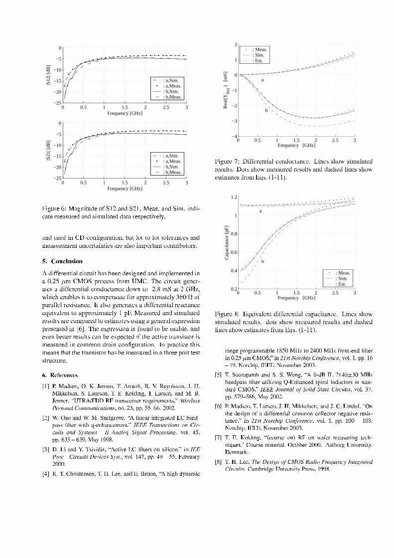
0 0.5 1 1.5 2 2.5 3−25
−20
−15
−10
−5
0
Frequency [GHz]
|S12
| [dB
]
: a,Sim.: a,Meas.: b,Sim.: b,Meas.
0 0.5 1 1.5 2 2.5 3−25
−20
−15
−10
−5
0
Frequency [GHz]
|S21
| [dB
]
: a,Sim.: a,Meas.: b,Sim.: b,Meas.
¦1a^\p\=F<w¢1f?A@H^\Ga k pTB\<·P\mx ¥>@>GTBxf,¥QT?±<N@NDK1@>GTBxTa q!Ta GTBadN@>k<qr<N@NDip\=F<NB@>GTBDia qpE]@>k<NBB@>kd@*=F<QDS|T<CHk a [\<C]
@>GTBrpfDF<NBa G!g*s²NPGT³f^\p\=_@>k adPG1MR\pk]PkkdPt]Pk,kdP\] <>=_@>GEC<QD@>GTBqr<N@NDip\=F<Hqr<HGk\pGEC<>=ikd@>a Gk a<QD@K=F<`@H]dD_PVa q|fPQ=ikd@>GkENPGk =ia R\pkdPQ=XDK ©w¬1H¾ ¯_°¬uÌBamjmS<>=F<HGk ad@H]\Ha =FHpa kEhT@NDRT<C<HGB\<QDia^\GE<NB@>GTBVa q|T] <Hqr<HGk<NBwa G@t1 E!,q(g*?AVx±|=_P\C<QDXDVmj=_Pq ~V?±g`OlhE<Ha =FHpa k*^<HGE<>=i@>k<QDw@BamjmS<>=F<HGk ad@H]NPGTBpEHkd@>GEC<BPQ`GtkdP«y1 qtx#@>k!`ZVM`haHh<HGT@KRT] <QDa k1kdPNPq|T<HGfD_@>k<·miPQ= @K||=_Pna qt@>k<C] ¡\¢\£.P\m|f@K=_@H] ] <C]E=F<QDiajDikd@>GEC<\oSk@H]dD_P^<HGE<>=_@>k<QDW@VBamjmS<>=F<HGk ad@H]=F<N@HHkd@>GEC<<N¤pa [\@H] <HGkkdP@K||=_Pna qt@>k<C] #¥`|E¦T?±<N@NDip\=F<NBt@>GTBDia qpE]@>k<NB=F<QDipE] kjD@K=F<+NPq|f@K=F<NBkdP`<QDik a qt@>k<QDpfDia GE^@*^<HGE<>=_@H]<>n\|=F<QDXDiadPG|=F<QDF<HGk<NBa G%´¢¶_lOlhE<<>n\|=F<QDXDiadPGajD+miPpGTBkdPRT<`pfD_@KRT] <ME@>GTB<>[\<HGRT<Hk k<>==F<QDipE] kjD N@>GRT<`<>n\|T<CHk<NBVamk hE<V@HHk a [\<·k =_@>GfDiajDikdPQ=lajDqr<N@NDip\=F<NBta G%NPqqtPG!BQ=_@>a G&NPGT³f^\p\=_@>k adPGoSG«|=_@HHk aC<k hajDqr<N@>GfDk hT@>k\k hE<+k =_@>GfDiajDikdPQ=hT@NDRT<+qr<N@NDip\=F<NB·a G@*k h\=F<C<*|fPQ=ik\k<QDikDik =ipEHk p\=F<\
!"$#&%')(*+,!"$!"$#.-)/021 354617#98:&;8<!>=?"?@7AB35"$#C+;D2E@ F?F?!G7!"$#&H)I&>JLKA!"$#9-)MN;(<35G L@ "O #C-)I&,KA!"$#.>"PQR+,!"?"!>K#CS>T-C8N/VU WXXY8NW1 KB>"$Z!@ [?!>KVK!\LJ?@ K!0]!"?17A# ^_*` abc b>dAde bad,fLg?h ci.fLjj*k5g ` lh m ` fLg?d#L" 3 5no#qp?p5r?r5s$t?t#n?u?u?n$
nPvw xy3z>"vwQH$"!G O5KB3q[?!5#;S6/|G @ "!q,KN@ "?1 !O5KB>1 !zI.~$>"p$qA*G 1 !>Ky@ 1 \7!"? >"Z!0]!"?17# ^PCC|?ah?g?dAhlqm ` fLg?dfLgQi&` aAlqk?` m dh?g?qLd>m b>jdw*62<g?h c f5 ` ?g?h c e a6f?lqb>dAd>` g?$#'[35G6<r #p?pLt?oLrst?oL #5>=P>?
o?X2IC@>".;-@ [?@ L@7A#.S6/yZ1 @ [?!]I.G 1 !>KA35"@ G @ Zq35"$# ^@ "Ce a6f?l'&i&` a6lqk?` m dN'b>q` lqb>d<qLd>m # [35G6), #p?p2szr?r #$W;!>~?KJ ,K=n?u?u?u$
(*L-)LK@71 !"$!"$# -)LD2?I.!!5#$>"2MNLRKJ?J?"$#S6/?@ OLzL=?" >02@ Z
0 0.5 1 1.5 2 2.5 3−4
−3
−2
−1
0
1
2
a
b
Frequency [GHz]
Rea
l(YIN
d )
[mS]
: Meas.: Sim.: Est.
¦1a^\p\=F< ·sVamjmS<>=F<HGk ad@H]NPGTBpEHkd@>GEC<\Ula GE<QD`DihTPQDia qpE]@>k<NB=F<QDipE] kjDKlsPkjD+DihTPQ8qr<N@NDip\=F<NB=F<QDipE] kjD+@>GTBB@NDihE<NB] a GE<QD+DihTPQ<QDik a qt@>k<QDlmj=_Pq¸W¤EDK × ¥HK¥¥>ÙX
0 0.5 1 1.5 2 2.5 30.2
0.4
0.6
0.8
1
1.2
a
b
Frequency [GHz]
Cap
acita
nce
[pF]
: Meas.: Sim.: Est.
¦1a^\p\=F<«TVW¤pa [\@H] <HGk BamjmS<>=F<HGk ad@H]lN@K|f@HHa kd@>GEC<\rUla GE<QDDihTPQDia qpE]@>k<NBt=F<QDipE] kjDK«BPkjDDihTPQ qr<N@NDip\=F<NBt=F<QDipE] kjDV@>GTB!B@NDihE<NB] a GE<QDWDihTPQ<QDik a qt@>k<QDlmj=_Pq¸W¤EDK × ¥HK¥¥>ÙX
KB>"O?!p?KB3LO5KB>020,~G !5r?u]EDy1 3'nLu?u]EDy47KB35"?1 7!"]G 1 !>K@ "yu$ n?rC0%yH;# ^&@ "$qd>m5 fa6l>¡ ` ¢Pi.fLg7£Lbab>glqbq#5[35G6#p?p tsP> #5¤*3qKZ?@ p#5¥6MCMCM#¤*3q[?!0'~ !>K.n?u?uo
r-)CH3?3qKB,p$>"?1 w>"H)CH)v35"O #NS6/¦u7LRY¥6In;,u §]oLuEDy~$>"5p$qAG 1 !>KNJ?1 @ G @ @ "Oz¨y MC"? >"Z!6p@ KB>G9@ "LJZ1 3qKAV@ "P1 >" ,K%yH;# ^'CCª©fk?ag?h cf £zfc ` m h m bi&` a6lqk?` m d#9[35G6)oL #p?p5r??5s r Lt#?>='n?u?u?n$
t?L !"$# -)?I&,KA!"$# +LD2?E@ F?F?!G7!"$#>"2+LIC@ "354B#S%"1 !]?!5@ OL"354]L@ 4 4!>K!"?1 @ >G&Zq3502035"EZq35G G !Z1 3qK"!O>1 @ [?!2K!5@7B1 >"Z!5# ^@ "w$qd>m fa6l>¡ ` ¢Yi.fLg7£Lbab>glqbq#V[35G6#p?p>u?us>uo#¤*3qKZ?@ p#5¥6MCMCM#¤*3q[?!0'~ !>K.n?u?uo
-)NMNV(<35G L@ "O #2Sq« Zq35JLKA!35"¬8NWY35">4!>Kz0]!qqJLK@ "O1 !Z "?@ \LJ!5, ^'<35JLKA!*0>1 !>K@ >G7#%Z1 3q~ !>K<n?u?u?u$2/*>G ~$3qKOT"?@ [?!>KA@ 1 =5#Xy!"?0,KF
L-)D2I.!!5#; ¡ b'b>d>` ?gf £zi)®¯<]°&h? ` f±)ab²k?b>glA2g m bB ah m b>i&` a6lqk?` m d;<>0'~?K@ ?O?!<T"?@ [?!>KA@ 1 =*K!5AA#>?

PhD Thesis R04-1026, March 3, 2005.Texas Instruments Denmark A/S & RISC group AaU
An RF CMOS Q-enhanced LC Resonator
P. Madsen, T. Larsen, J. H. Mikkelsen and J. C. Lindof
Accepted at the 22th NorChip ConferenceOslo, Norway, pp ?? ,November 2004.
PAGE 111


!
"$#&%('*),+.-/#10$243657),098;:=<,>@?=),)7%A+;'*BDC.CE#1>D-/#10GFH3657#10.-(IKJG%ABD-/LMBD),0NOBD0.+.<=P42Q),0.+SRG<7%AT.#10UNO)7%A-/#10GFV6WYX1Z4[=\D]&[@^ _@`baOWc]b^d[feQWc]ba(Zg_@hQikjmlfnoipZcq r&s/_@t&uEZY]AvQw.\xl&yzvH |Hd[@s~]6noyEV7\DAn4ipZcq r&s/_@t$]b |HWY_[@ ^ 1da(ZYqDHAa(Zcv,(hAs~a ZoZY` vHh
T.-/Lg%A)7ALA1 ,g74ko~,1DY$Y b A ~bHb ¡pcHYbDYpY17DYYb m¢K£ & ¢ ¢44DY1 1E¤$¥mYAbH1oY K¦§¨ Hb©M74@A Hª«A.¬&bo®¯¥¬~°4± ²K³Q´gµ¶AYbY ·4 4 D4b QHb ¸ &¥dAo4b@A Qp~ 14 ¹mA¥·/ 1Y « &¥dAo4b@A ºY b A ~bMµ«¶1¥ ,1@Hpo 4DQpcHYbDY £~o~7~1Y1 pHb ¸Y~»1¥m4 D4b ¼½4D 14 / 1Y « ¯ AOY b 1¥ ~b¹ 7¹m~·/ 1HQAo4b@A¾km¢E¿k²K³Q´. p A.Yg QA Y¹m¢G ADYg~AA A7oY1Db¢/DcÀ1HY1¾cµÁfÂÄà 0.Lg%H<,+.ÅGALMBD<,0Æ mWc]bÇ1ZY]AÈoWcaOWc]b^7Wc]1Zgr1q W/[$vbW/[@tH]£sHÉGÇbtHÇ1 Æ s~]1mÈcÇb ËʹyÄ_xW/[Ìs~]1ZY^s/_[7`&[@ ]Atp^ ÇAWqs/ÍQ Æ ]AvH`AÈc^s/_[,^ Ç1ZY^&`&[@`1Zcq q OZg_xWZg|HZYqZgr1q W ]¯[@^ZY]AvAZg_xvyEÎzÏl£b_ÌsHÈoW/[[xW/[gKl&WY|HWY_ÌZcq7 aº1q WcaOWc]b^ZY^ s~]&[ksHÉÆ mWc]bÇ1ZY]AÈoWovpʹyÐ_xW/[Ìs~]1ZY^s/_[7Ç1Zg|HW½r1WoWc]º_xWY&s/_@^Wovp ]O^ ÇAWq ^WY_ÌZo^ `H_xWpÑxÒon/Ó&nHÔbn4Õ1ÖÌbeÉdÉDWY_xWc]b^ ZcqH aº1q WcaOWc]b^ZY^ s~]&[=Í$ÇAWY_xWkZG]AWctAZo^ |HW½È4s~]AvH`AÈc^ZY]AÈoWd[7ÈY_xW4ZY^Wov`&[@ ]At&sA[@ ^ |HWGÉDWoWov~r&ZcÈch$r1Wc^ÍWoWc]^ÍsË^ _ÌZY]&[@d[@^s/_[pZg_xW(a(sA[@^.È4s~a a(s~]ÐÑxÒon=Ó&n7Ô~ÖÌ«×Qs/ÍWY|HWY_xn¹[Ìsbq `b^ s~]&[EÍ$ÇAWY_xWpZ[@ ]Atbq W^ _ÌZY]&[@d[@^s/_d[E`&[xWov ^sHtbWc^ ÇAWY_Í$ ^ Ç _xW4ZcÈ4^ |HWQÈ4s~aº&s~]AWc]b^d[7Ç1Zg|HWQZcq[Ìsºr1WoWc]º_xWY&s/_@^WovÑ Ó1nHÕ1ÖÌV7Çbd[¹&Zg1WY_b_xW/[xWc]b^d[kZºvHÉdÉDWY_xWc]b^ Zcq Æ mWc]bÇ1ZY]AÈoWovOʹyS_xW/[Ìs~]1ZY^s/_.Í$ÇAWY_xW^ ÇAW]AWctAZY^ |HW½È4s~]AvH`AÈc^ZY]AÈoW.d[tbWc]AWY_ÌZY^WovpÍ$ ^ Ç(ZkvHÉdÉDWY_xWc]b^ ZcqAÈc _xÈc`b ^^ Ç1ZY^&`&[xW/[7r&s~^ Ç^ _ÌZY]&[@d[@^s/_[ZY]Avp_xW4ZcÈc^ |HWkÈ4s~aº&s~]AWc]b^d[g1V7ÇAW$Èc _@Èc`b ^¹Ç1Z4[½r1WoWc] aº1q WcaOWc]b^Wov( ]£ZOØbdaOWc^Zcq7qZYAWY_xn,[@ ]Atbq W&sHq HnÙ ÓAØÚ=aÛyEÎzÏlºb_ÌsHÈoW/[[gܹ R J.#ËÝ9ÞÌ#10.J.),0GA#1+UßË#1-/<,0.),LM<7%V7ÇAWk_xW/[Ìs~]1ZY^s/_7d[G[@Ç1s/Í$] ] 6tH`H_xW(Ò/,\D^d[.Zk&Zg_ÌZcq q Woq1ʹy;^ZY]bhÍ$ ^ Çp^ `b]AW4Zgr1q W Æ ÉDZcÈc^s/_,ZY]AvQÈoWc]b^ _xWGÉd_xWoàH`AWc]AÈYb4V7ÇAWGÈoWc]b^ _xWGÉd_xW4àH`AWc]AÈY$d[,È4s~]b^ _ÌsHq q Wov½rAZ½[xÍ$ ^ÈcÇAWov|HZg_ÌZcÈc^s/_6r&ZY]bh6ncÈ4s~aº&sA[xWovsHÉ7áA|HWk|HZg_ÌZcÈc^s/_[g&V7ÇAW$|HZg_ÌZcÈc^s/_[¹Zg_xWk aº1q WcaOWc]b^WovZ4[,&ZY _[sHÉ]b67VE[fâDã u ^s$ã uxäoå ~iQq q/^ ÇAW¹67VE[Zg_xW Ù ÓAØGÚ=aUqs~]At.rH`b^/^ ÇAWc _Í$vH^ ÇO ]AÈY_xW4Z4[xW/[EÉd_Ìs~aæÒ Ù Ú=aâDã u ZY]Av(ã cå s~|HWY_Ó Ù nHÕ Ù ZY]Avç/Ù Ú=aÄ^s Òcè Ù Ú=a¨âDãé.ZY]AvQã uxäcå HV7ÇAW67VE[=Zg_xW¹rAZ4[xWovZY^H^ ÇAWtAZY^W/[Í$ ^ Ç(Ó6 ØêëZY]Avº^ ÇAWQ|HZg_ÌZcÈc^s/_,r&ZY]bhºd[.È4s~]b^ _ÌsHq q WovprA eQy|HsHq ^ZctbW/[Zgb1q Wov^sËv~_ÌZY ]£ZY]Av£[Ìs~`H_xÈoW(sHɽW4ZcÈcÇË67VS^ ÇH_Ìs~`AtHÇìí¹î,ï u ìí¹î,ï7ð kV7ÇAW/[xW|HsHq ^ZctbW/[GZg_xWWc ^ ÇAWY_ Ù s/_GÓ6 Ø êñZY]AvÉ@s/_xÈoW/[7W4ZcÈcǺ67V¸ ]b^sp ]~|HWY_[@s~]Qa(sHvbW$s/_¹ÍW4ZYh ZcÈoÈc`ba `AqZY^ s~]a(sHvbW_xW/[D1WoÈc^ |HWoq b4V7ÇAW.qZg_@tbW/[@^bÈ4Zg&ZcÈc ^ZY]AÈoWd[7s/rA^ZY ]AWov½ ]Q ]1|HWY_[@s~]a(sHvbWHV7ÇAWk ]AvH`AÈc^s/_=d[.Zk^Zgb1WovQ1qZY]AWY_[DA _ÌZcq6vbWY|HÈoWÍ$ ^ Ç É@s~`H_,Í$ ]AvH ]At1[7ZY]Av [@ba aOWc^ _@ºZg_Ìs~`b]AvQ^ ÇAW½^ZgbA ]At&s~ ]b^D\D^,d[G aº1q WcaOWc]b^Wov ]¡^ ÇAW^ÍsO^s/KaOWc^Zcq=qZYAWY_[½ZY]AvOb_Ìs~|HvbW/[rAZ4[EÉ@s/_7r&s~^ Ç ^ ÇAWQ|HZg_ÌZcÈc^s/_,r&ZY]bh(ZY]Avº^ ÇAW Æ mWc]bÇ1ZY]AÈoWcaOWc]b^&Èc _@Èc`b ^D~V7ÇAW,rAZ4[6|HsHq ^ZctbW7d[fZgb1q WovkZY^/^ ÇAW¹^ZgbA ]AtE&s~ ]b^mngÍ$ÇAWY_xW7 ^d[fvbWoÈ4s~`H1q WovErAk^Ís½]b67V¡È4Zg&ZcÈc ^s/_[6È4s~]1á&tH`H_xWov. ]$ ]~|HWY_[@s~]a(sHvbWâDã uMu ZY]AvKã uÌYå ½V7ÇAWQ]AWctAZY^ |HWÈ4s~]AvH`AÈc^ZY]AÈoW$d[GtbWc]AWY_@ZY^WovrA ã uÌò nHã uxó n~ô uMu n~ô uÌ ZY]Avºô uÌò n/Í$Çbq W$ã u ð n~ã uÌõ n/ö u nö ZY]Av¡ô uxó Zg_xW`&[xWovOÉ@s/_7rAZ4[@ ]At(ZY]Av([@^ZgrAq d[ÌZY^ s~]wGWoÉDWY_^s
6tH`H_xW£Ò~Q\Daº1q WcaOWc]b^Wov¡Ê¹yÄ_xW/[Ìs~]1ZY^s/_kÍ$ ^ Ǹ^ `b]AW4Zgr1q W ÈoWc]b^ _xWÉd_xWoàH`AWc]AÈYpZY]Av Æ ÑØ1n1èHÖ¹É@s/_.ZpvbWc^ZYq WovOvbW/[xÈY_@ A^ s~](sHɹ^ Çbd[.Èc _xÈc`b ^DEiÛvHW$AÇ1s~^ssHÉ^ ÇAW½ aº1q WcaOWc]b^WovÈc _xÈc`b ^Ad[[@Ç1s/Í$]Q ]6tH`H_xWGÓ6÷¹ÂÄø )7%A)7ALM<7%¡ùO),0.Cl1 a `AqZY^ s~]&[Mn6Í$ÇAWY_xWQa(sHvbWoq[GÉd_Ìs~a^ ÇAWvbW/[@tH]¡hb ^7Zg_xW`&[xWov( ]^ ÇAW½|HZg_ÌZcÈc^s/_6r&ZY]bh6ncW/[@^ a(ZY^W/[=^ ÇAW.`Hb1WY_fÉd_xWoàH`AWc]AÈY$q a ^&sHÉ6^ ÇAW_xW/[Ìs~]1ZY^s/_.[@tH]bá&È4ZY]b^q OÇbtHÇAWY_¹^ Ç1ZY]OaOW4Z4[@`H_xWov6V7ÇAWa(ZY^ÈcÇOd[àH`b ^W(tAsbsHvËZY^^ ÇAW(qs/ÍWY_$Éd_xWoàH`AWc]AÈYq a ^Di]«ZY]1Zcq &[@d[sHÉ$ZvHÉdÉDWY_xWc]b^ ZcqE|HZg_ÌZcÈc^s/_rH`bq v«Í$ ^ Ç;Ô~Ó Ù X Ù ÓAØÚ=aú]b67VE[p ]AvHÈ4ZY^W/[º^ Ç1ZY^½^ ÇAWvbW/[@tH]zhb ^½`b]AvbWY_xW/[@^ a(ZY^W¡^ ÇAWÈ4Zg&ZcÈc ^ZY]AÈoWK ]ÍW4ZYh¸ZcÈoÈc`ba `AqZY^ s~](a(sHvbW [@tH]bá&È4ZY]b^q bû9Çbq Wº^ Çbd[kÈ4ZY]WYX11qZY ]¡^ ÇAWs/r6[xWY_x|HWovr1WcÇ1Zg|Hs~`H_xnb ^7Zcq[Ìs aº1q W/[.^ Ç1ZY^faOW4Z4[@`H_xWovvAZY^Zk]AWoWov^sQr1W$`&[xWovºÉ@s/_7^ ÇAW|HZg_ÌZcÈc^s/_[,^s s/rA^ZY ] ZcÈoÈc`H_ÌZY^W$W/[Ì^ a(ZY^W/[sHÉk^ ÇAW¡Éd_xWoàH`AWc]AÈY¸Éd_Ìs~aú[@ a `AqZY^ s~]&[g«]AÉ@s/_@^ `b]1ZY^Woq ^ ÇAWQ|HZg_ÌZcÈc^s/_,r&ZY]bhº`&[xWovº ]O^ ÇAWk_xW/[Ìs~]1ZY^s/_7Ç1Z4[]1s~^&r1WoWc] aº1q W4aOWc]b^Wov(Z4[GZ[@^ZY]AvADZcqs~]AWp[@^ _@`AÈc^ `H_xW~nAZY]AvOÈ4ZY]O^ ÇAWY_xWoÉ@s/_xW$]1s~^6r1WaOW4Z4[@`H_xWov69\D]&[@^W4Zcv£aOW4Z4[@`H_xWov«vAZY^ZKÉd_Ìs~aæ^ ÇAW¸Ô~Ó Ù X Ù ÓAØËÚ=a

6tH`H_xWGÓAeW.AÇ1s~^sQsHÉ^ ÇAWG aº1q WcaOWc]b^Wovk_xW/[Ìs~]b^s/_@|HZg_ÌZcÈc^s/_.d[k`&[xWov¡^sOb_Ìs~|HvbWQ_Ìs~`AtHÇKW/[@^ a(ZY^W/[$sHÉE^ ÇAWº|HZg_ÌZcÈc^s/_r&ZY]bh¡V7ÇAWO|HZg_ÌZcÈc^s/_[Zg_xW ÇbtHÇ1 Æ vbWY|HÈoW/[gKV7Çbd[$aOW4ZY]&[k^ Ç1ZY^^ ÇAW$_xW4Zcq6&Zg_@^=sHÉ7^ ÇAWaOW4Z4[@`H_xWovº aº1WovAZY]AÈoW$d[½[@a(Zcq qfÈ4s~aº&Zg_xWov^s^ ÇAW$ a(ZctH ]1Zg_@p&Zg_@^DfwGWoqZY^ |HWp[@a(Zcq q6WY_D_Ìs/_[7 ] ^ ÇAW$aOW4Z4[@`H_xW4aOWc]b^d[a(ZY^ ÇAWY_xWoÉ@s/_xW^ _ÌZY]&[xqZY^WE^sqZg_@tbWEWY_D_Ìs/_[6 ]Q^ ÇAW.W/[@^ a(ZY^W/[sHÉ&^ ÇAW¹_xW4Zcq/&Zg_@^bsHÉ&^ ÇAWE aº1WovAZY]AÈoWH~Ïk]Aq $aOW4Z4[@`H_xWcaOWc]b^d[fs~]$^ ÇAWÔ~Ó Ù X Ù ÓAØGÚ=a |HZg_ÌZcÈc^s/_xngÍ$ÇAWY_xWE^ ÇAW_xW4Zcq/&Zg_@^~d[=qZg_@tbWY_6^ Ç1ZY] WY_ÌsZg_xWZcÈoÈoWYA^Wov6V7ÇAW$vbW4mWcaºr1WovbvbWovpZY]Av Zg|HWY_ÌZctbWovl6&Zg_ÌZYaOWc^WY_[Éd_Ìs~aÄ^ ÇAW/[xW.aOW4Z4[@`H_xWcaOWc]b^d[=Zg_xW.`&[xWov^sk_xWYb_xW/[xWc]b^H^ ÇAWG|HZg_ÌZcÈc^s/_[ ]Q^ ÇAW½[@ a `AqZY^ s~]&[6b_xW/[xWc]b^Wovk ]Q^ Çbd[&Zg1WY_@~V7ÇAW.|HZg_ÌZcÈc^s/_&r&ZY]bhd[,vH |HvbWov$ ]p^Ís[xWoÈc^ s~]&[gbl&WoÈc^ s~]KÒE ]AÈoq `AvbW/[^ _ÌZY]&[@d[@^s/_[¹ã u^sQãEÍ$Çbq W½[xWoÈc^ s~]QÓk ]AÈoq `AvbW/[^ _ÌZY]&[@d[@^s/_[=ãé.ZY]Avpã uxä ~V7ÇAWvHÉdÉDWY_xWc]b^ Zcq~È4Zg&ZcÈc ^ZY]AÈoW.sHÉf[xWoÈc^ s~]¡Òd[=W/[@^ a(ZY^Wov$^s(ÒcØbèkÉm ] ]~|HWY_[@s~]Qa(sHvbW$ZY]Av ç/Ù Ém¡ ]ºÍW4ZYh ZcÈoÈc`ba `AqZY^ s~]Qa(sHvbWHAV7ÇAWWoàH`b |HZcq Wc]b^=È4Zg&ZcÈc ^ZY]AÈoW/[½Zg_xWºW/[@^ a(ZY^Wov¡^s¯Ò Ù ZY]Av ç ¡Ém«É@s/_[xWoÈc^ s~]Ó6¹ÂÄà 0.+.ÅGALM<7%V7ÇAWG ]AvH`AÈc^s/_fd[ZY] aº&s/_@^ZY]b^H&Zg_@^&sHÉ^ ÇAWkvHÉdÉDWY_xWc]b^ ZcqHʹy¯^ZY]bhZY]Av ] ^ ÇAWkb_xW/[xWc]b^Wov aº1q WcaOWc]b^ZY^ s~]p ^d[EZcq[Ìs aº&s/_@^ZY]b^&É@s/_^ ÇAW¡rAZ4[@ ]At69\D^Gd[O[@`AÉmá&ÈcWc]b^.^s£hb]1s/Í^ ÇAWK ]AvH`AÈc^s/_ [QÓA&s/_@^ÈcÇ1Zg_ÌZcÈc^WY_@d[@^ È/[=ZY^ ò ZY]Av ó É@s/_=[@ a `AqZY^ s~]psHÉ&^ ÇAWE_xW/[Ìs~]1ZY^s/_ [vHÉdÉDWY_xWc]b^ Zcq, aº1WovAZY]AÈoWHOV6s£[@ a `AqZY^W ^ ÇAWOWoÉdÉDWoÈc^d[$^ ÇAW¡[@`Hb1q ]AWc^Ís/_@h a tHÇb^Ç1Zg|HWps~]O^ ÇAW_xW/[Ìs~]1ZY^s/_l6&Zg_ÌZYaOWc^WY_[.ZpÔH&s/_@^_xWYb_xW/[xWc]b^ZY^ s~] d[E_xWoàH`b _xWov6iñÔH&s/_@^6a(ZY r1W_xWYb_xW/[xWc]b^WovrA[@ X aº1WovAZY]AÈoW/[=Z4[,q q `&[@^ _ÌZY^WovQ ]6tH`H_xWkÔ1
6tH`H_xWkÔ&&ÔH&s/_@^H_xWYb_xW/[xWc]b^ZY^ s~]QÍ$ ^ ÇO[@ Xp aº1WovAZY]AÈoW/[g\D](^ ÇAW [@ a `AqZY^ s~]&[ ò d[GtH]1s/_xWov ^sK[@ aº1q Ém¡qZY^WY_.W/[@^ a(ZY^W/[sHÉ^ ÇAWkáA|HW._xWca(ZY ]b ]At$ aº1WovAZY]AÈoW/[g/V7ÇAW/[xWkZg_xW½W/[@^ a(ZY^WovpÉd_Ìs~aaOW4Z4[@`H_xWcaOWc]b^d[½sHÉE^Ís(^W/[@^E[@^ _@`AÈc^ `H_xW/[=s~]AWºÍ$ÇAWY_xWp^ ÇAW ]AvH`AÈ4^s/_7d[Es/1Wc]6n~Z4[.[@Ç1s/Í$] ] 6tH`H_xW½Õ1Z/nHZY]Av s~]AWkÍ$ÇAWY_xWk^ ÇAWk^Zg d[
[@Ç1s/_@^Wov¡Z4[k[@Ç1s/Í ]¡6tH`H_xWQÕHr&GV7ÇAWpWoàH`b |HZcq Wc]b^,ÔH&s/_@^&_xWYb_xW4[xWc]b^ZY^ s~]&[7Zg_xW$[@Ç1s/Í$]p ]p6tH`H_xW/[=ÕAÈkZY]Avpv6
6tH`H_xWGÕf&ZkZY]Avr=A^W/[@^[@^ _@`AÈc^ `H_xW/[,Í$ ^ Ç s/1Wc]ZY]Avº[@Ç1s/_@^WovrAZ4[&s~ ]b^d[¹_xW/[D1WoÈc |HWoq b,ÈpZY]AvOv=V7ÇAWc _7_xW/[D1WoÈc^ |HWpÔH&s/_@^6WoàH`b |HZoq Wc]b^d[g½s~^ ÇQ ]AvH`AÈc^s/_6^W/[@^6[@^ _@`AÈc^ `H_xW/[=Zg_xWE aº1q WcaOWc]b^Wovs~]pZ½[@ ]Atbq WGqs~^âdqs~^EÒ å 6s~`H_¹ÈcÇb 6[¹ÍWY_xWkaOW4Z4[@`H_xWovºZY]Avp^ ÇAWl6&Zg_ÌZYaOWc^WY_[¹Zg_xWZg|HWY_ÌZctbWov ZcÉm^WY_vbW4mWcaºr1WovbvH ]At6fV7ÇAWWoàH`b |HZcq Wc]b^¹&Zg_ÌZYaOWc^WY_[Zg_xW£È4Zcq Èc`AqZY^Wov;ZY]Avz`&[xWovÐÉ@s/_ W/[@^ a(ZY^W/[(sHÉp^ ÇAWË_xWoq WY|HZY]b^½ a(1WovAZY]AÈoW/[,Z4[[@Ç1s/Í$]p ]p¹à1[g1âMÒ å ^sâmØ å
u
uMu uÌ âMÒ å
M Yu âdÓ å
ó
Yu uÌ âDÔ å ð
uMu uÌ uMu uÌ
âÕ å õ
M Yu M Yu
âmØ åÍ$ÇAWY_xW½^ ÇAW!¹&Zg_ÌZYaOWc^WY_[Mn4s/rA^ZY ]AWovpÉd_Ìs~a ^ ÇAW½^W/[@^f[@^ _@`AÈc^ `H_xW/[= ]6tH`H_xW/[=Õ1Z½ZY]AvQÕHrn/Zg_xWGa(Zg_@hbWovQÍ$ ^ Ç#" ZY]Av%$_xW/[D1WoÈc^ |HWoq bV7ÇAW$^W/[@^,[@^ _@`AÈc^ `H_xW$ ] 6tH`H_xW$Õ1Zkd[ aº1q WcaOWc]b^Wovºs~] ^ ÇH_xWoWvHÉ@ÉDWY_xWc]b^&qs~^d[¹ ]AÈoq `AvH ]AtQ^ ÇAW$s~]AWkÍ$ ^ Ǻ^ ÇAW½_xW/[Ìs~]1ZY^s/_¹âdqs~^fÔ å &V7Çbd[a(ZY(r1WQ`&[xWov(^sºb_Ìs~|HvbWpZY]s~|HWY_x|HWYÍ sHÉ^ ÇAW_xWY1W4ZY^ZgrAq ^ ¡sHÉ^ ÇAW$vAZY^ZkÉd_Ìs~aÛqs~^Ò/6V6Zgr1q WOÒ½q d[@^d[¹^ ÇAW$vHÉdÉDWY_xWc]b^ Zcqb ]AvH`AÈc^ZY]AÈoW~n& n¹vHÉdÉDWY_xWc]b^ Zcq¹È4s~]AvH`AÈc^ZY]AÈoW~n('#)@nZY]AvË^ ÇAW Æ ÉDZcÈc^s/_QZ4[QaOW4Zo[@`H_xWov(É@s/_ ]AvH`AÈc^s/_[EÉd_Ìs~a ^ ÇAWpvHÉdÉDWY_xWc]b^qs~^d[gGV7ÇAW Æ d[GÈ4Zcq Èc`1qZY^WovÉ@s/_+*-, /.021 Î¯× `&[@ ]At(Ñ bÖ
3
54 *-, & '#) âmè å
V6Zgr1q W£Ò~kίW4Z4[@`H_xWovKvHÉdÉDWY_xWc]b^ Zcq Æ n & ZY]Av6'#)EÉ@s/_½^ ÇAW(ÔH&s/_@^ ]AvH`AÈc^s/_@ qs~^ Æ & Ñ ]A×QÖ '#)7Ñ a(l6ÖÒ 6 è Ø& Ó6ÒÓ 6 Õ Ø& Ø Ó6ÒÔ 6 è Ø& è ÓV7ÇAW$|HZcq `AW/[¹sHÉ= ]AvH`AÈc^ZY]AÈoW½vHÉdÉDWY_,Í$ ^ Ç Ù Óp]A×UÍ$Çbq Wk^ ÇAW$|HZcq `AWsHÉ^ ÇAWkÈ4s~]AvH`AÈc^ZY]AÈoWEvHÉdÉDWY_=Í$ ^ Ç Ù Òa(l=7  Ý9ÞÌ#10.J.),0GA#8Ä#10.LV7ÇAW Æ mWc]bÇ1ZY]AÈoWcaOWc]b^.Èc _xÈc`b ^½d[([@ a `AqZY^WovÐZY]Av«aOW4Z4[@`H_xWov« ][@^ZY]AvADZcqs~]AWpÈ4s~]1á&tH`H_ÌZY^ s~]OÍ$ ^ Ç¡^ ÇAW [ÌZYaOWQrAZ4[@ ]At¡È4s~]AvH ^ s~]&[

Z4[ ^ ÇAWK_xW/[Ìs~]1ZY^s/_@ V_ÌZY]&[@d[@^s/_[ Zg_xW«[@ a `AqZY^Wov¯`&[@ ]At¯^ ÇAW¸vbW4[@tH]Ohb ^=Í$Çbq W$_xW/[@d[@^s/_[.ZY]Av(á1XbWov È4Zg&ZcÈc ^s/_[.Zg_xW$_xWYb_xW/[xWc]b^WovÍ$ ^ Ç¡vbW4mWcaºr1WovbvbWovÓA&s/_@^fl6&Zg_ÌZYaOWc^WY_[¹aOW4Z4[@`H_xWovOs~]K[@^ZY]AvAZcqs~]AWp aº1q WcaOWc]b^ZY^ s~]&[GsHÉE^ ÇAW/[xWºÈ4s~aº&s~]AWc]b^d[g$V6s¡|HWY_@Ém¡^ ÇAWÆ mWc]bÇ1ZY]AÈoWcaOWc]b^HÈc _xÈc`b ^mnc^ ÇAW½vHW½ÍZ4[,a(s~`b]b^WovQs~]Zy oV7ÇAW[@`Hb1q (ZY]AvOÈ4s~]b^ _ÌsHq6|HsHq ^ZctbW/[EÍWY_xWpZgb1q Wovº^ ÇH_Ìs~`AtHǺ^ Çbd[y ^s¡Wc]&[@`H_xWov _xWY1W4ZY^Zgr1q WqsbZcv1[gV7ÇAW Æ mWc]bÇ1ZY]AÈoWcaOWc]b^fÈc _xÈc`b ^=d[É@s~`b]AvQ^sQr1WQ[xWc]&[@ ^ |HW½^sQb_Ìs/rA ]At6AV6sWY|HZcq `1ZY^W½^ ÇAWG_xWY1W4ZY^ZgrAq ^ sHÉ&^ ÇAWEaOW4Z4[@`H_xWcaOWc]b^d[Mng^ ÇAW.Èc _xÈc`b ^bd[faOW4Z4[@`H_xWovZE]b`baºr1WY_sHÉ^ aOW/[gQV7ÇAWp^W/[@^[@Ç1s~`Aq v(^ Çb`&[Eb_Ìs~|HvbWp|HWY_@[@ a qZg_$[xWc^d[ksHÉ.l6&Zg_ÌZYaOWc^WY_[frH`b^& ]&[@^W4ZcvºZ½|HZg_@ZY]AÈoWksHÉf`Hº^sÒGv-Ðd[s/r6[xWY_x|HWov6i^.Ò/ ç ÓAØ$× ^ Çbd[^ _ÌZY]&[xqZY^W/[¹^sOZ$|HZg_@ZY^ s~]OsHÉkÒ/ Óºa(l( ]O^ ÇAWvHÉdÉDWY_xWc]b^ ZcqÈ4s~]AvH`AÈc^ZY]AÈoWQZY]Av(Ó Ù Ém¸ ]¡^ ÇAWpWoàH`b |HZcq Wc]b^fÈ4Zg&ZcÈ4 ^ZY]AÈoWHËV7ÇAWY_xW d[]1sËÍZY«sHɽ^Woq q ]AtÉZY]H£sHɽ^ ÇAWOaOW4Z4[@`H_xWov[xWc^d[QsHÉkl6&Zg_ÌZYaOWc^WY_[GÇ1Zg|HW WY_D_Ìs/_[gOi]¸W/[@^ a(ZY^W d[$^ ÇAWY_xWoÉ@s/_xWs/rA^ZY ]AWov rAKZg|HWY_ÌZctH ]At ^ ÇAWpaOW4Z4[@`H_xWov¡ZY]Av(vbW4mWcaºr1WovbvbWov([xWc^d[sHÉ=l6&Zg_ÌZYaOWc^WY_[g/V7ÇAW.&Zg_ÌZ4[@ ^ ÈE_xW/[@d[@^ZY]AÈoWkZY]AvQÈ4Zg&ZcÈc ^ZY]AÈoW½sHÉ^ ÇAWp^ _ÌZcÈoW/[Gq W4ZcvH ]At(Éd_Ìs~a ^ ÇAWÈc _xÈc`b ^=^sO^ ÇAWQ&Zcv[@^ _@`AÈc^ `H_xW/[GZg_xWW/[@^ a(ZY^WovË^s9Ò ZY]Av;Ò Ù Ém¯_xW/[D1WoÈc^ |HWoq r&Z4[xWov£s~]Ëb_ÌsHÈoW/[[vAZY^Z~HV7ÇAW/[xW.W/[@^ a(ZY^W/[7Zg_xWk[@`HrA^ _ÌZcÈc^Wov$Éd_Ìs~aÄ^ ÇAW.aOW4Z4[@`H_xWovvAZY^Z^sW/[@^ a(ZY^Wº^ ÇAW(ZYa(s~`b]b^¹sHÉ Æ mWc]bÇ1ZY]AÈoWcaOWc]b^,vbWoq |HWY_xWov(^sK^ ÇAWʹy¯^ZY]bhbV7ÇAWG_xW/[@`Aq ^ ]AtQvHÉdÉDWY_xWc]b^ ZcqbÈ4s~]AvH`AÈc^ZY]AÈoWGZY]AvpWoàH`b |HZoq Wc]b^1È4Zg&ZcÈc ^ZY]AÈoW½Zg_xW[@Ç1s/Í$]Q ]p6tH`H_xWkØ&
1.4 1.5 1.6 1.7 1.8 1.9 2 2.1 2.2−2
−1.8
−1.6
−1.4
−1.2
Frequency [GHz]
Gd [
mS]
: Meas.: Sim.
1.4 1.5 1.6 1.7 1.8 1.9 2 2.1 2.21.02
1.04
1.06
1.08
1.1
1.12
Frequency [GHz]
Equ
ival
ent c
apac
itanc
e [p
F]
: Meas.: Sim.
! "# $ %&(' ) *+,)-$ %&".% +% ($0/-'1 24356$ !7389 7 ;:=<?>'1/@A%B'1 ! %$ %&1CD '1 '1"E?FHG I J%B$/-% $ %& <LKM =2A/=2N292 "#-+$ '1O2QPR) 9! '12J/=2NSI N&!72N2' R".BB2&!UT+/-$N$".V2S<W J:=< X=Y EZR[\.! %&=2R' $//N'1]^<9_< `"AT7242N&a ) 9! H%B'1 ! %$ %&1CbPR) 9! %&' RcU,d22N&U'10 ) A! M&G I M%B$/-% $ %& <->M) 2 "#-+$&!AI =2! '# )O2-'1@"A$%)A ) 4SI N&!#".BB2&!.! $D O$(PR ) Q ) (N$ (' ^ %&$ eJ! 0'/N' D <fMgihEj-k=lbmnboplMqEr9sqt uso>M) R2N /QO2N&!J'2 "# $0 ) R*+,)-$ %&". % % 2H$]-+/-$ !&!6'E %& !vxwpw&CyvxwVz=Cb ) 6` +/-'1H/=2N$ '1a' ) ! %'1$ !a".BB2".2J' ) 9I $N%'1V2S<7 ) +
"A'11CH ) E2 "# $ '1O2J %& ! ) "#/ &! $ %&1CM"# -0$ ! N'1 !%B$/-% $ %&y' O ) N%&=2@=2 "A$&!R'#:=< `JC|,.$ ! `4,9=2/ &% I & e#$ !E:+/-'1T+/-$N$".".BB2".2H' ) A2// e N%&.'19 ) 4~^y<OKM 4 ) #*+,)-$ %&".% +% ) =2V'1-$'1^PB2b".BB2&!J'140! "A'1&!J'14~^y$ ! ) y".BB2".2P/ B$&!J2N$I N= ".=2S<1>M) y! $O2N&!J Q ) (' '=PR J$' D $ &!JPR )4I $N%'12N&% '16:y PB$Q%&%"# $ '1"A' !$ !RI $N%'1@2N&% '1YR 1I V2'1"A' ! <9>M) #=2V'1-$'10 )O2J'1/ N$=2'1U#"#!6N$ .%& ,&G %$e<0>M) Q=2V'1-$'1PB2R2// &!APR )6Y< #C-QSMPB2y_< -XR$ !4 @%B'1O2".&!O< |Q" W <=>M) "A !R' ) T+/-$N$".V2H$2)-'=PR4 =2H$ !4c< W -'1%)42y2N& A ) "A !=2y' HTH::$ !ATOYYA$b$//N'1]^<:=< c.ZR[\ < >M) 2 "# $&!Q,&G %$eQ' ^ )2b-'1%)Q! V2b,N'1"i ) 0".BB2&!,&G %$e<E>M) ,&G %$eU' ) A-'1%)a2Q'1 !E' D AB+/ B$ D #'1I (4" D ' ".BB2".2S<Q>M) ! %&=2 ) &'10$]/=22@ 0 -+%&%N%=2@ Q ) R2 "# $ '1O2S<
1.4 1.5 1.6 1.7 1.8 1.9 2 2.1 2.2−16
−14
−12
−10
−8
−6
−4
Frequency [GHz]
|S11
| [dB
]
: Sim.: Meas.
1.4 1.5 1.6 1.7 1.8 1.9 2 2.1 2.2−16
−14
−12
−10
−8
−6
−4
Frequency [GHz]
|S22
| [dB
]
: Sim.: Meas.
0 y Hy$ O O y=V1-$1O ¡M =¢=NH £# ¤$&9= ¤ S #¥Q1(¢=NHS¦ N=1¦ bN$¦ N¤ONH ^£.BB&Q§¢-$N$£.VS ¨M R ¤ ¢ £# $ &(© ª&#«¬$ «B¤§ ¤$&J,N1£i©-1 J £# ¤$&Q$ £.BB&Q§¢-$N$£.V$ QB1£#¢-$&R Q R® ¨M (N1@1Q ( ¤ B1-§ $ &Ry¢.#¯ (£A 1¨M J ¤B1 $ &B¤§ ¤$&a,N1£L 9NQ (£.BB&E§¢-$N$£.V1 ¤ °a¦ $°¯ ¯¯£A &¨M (N1B$Q &1-1 © $±¢ ¤$ &JBM¢N1©-§ 7 &$ =S ?¨M 6B1 $ &9 £# ¤$&;17 9=V§1-$1£A$ =^ £ 0B1 $ & £# ¤$&J1 ² §,-$ &£. $ B1 $ &Q£.BB£. 1VM1¤1= ¨M B1 $ &£.BB&14 =V1-$1Q$¢¢N1±^ ¯ E£Ad£A¤ ¤ R -$UªR-$B$a© $±-§¢ &&R,N1£x y£.BB£.^ - ² §,-$ &£.B $ 1M1.¤1³- M¨M J £# $ &1´ µa¶· ¸1¹Hºb»p´ $^ ,&¼ $°4ºAM$±¢=N&©°½ ¾¿
µa¶· ¸1¹Hºb»0ÀÂÁÃRÄbÅÆd· ÇLÄ ºº È#É º Ⱥ6ÊJÊ Ë ¾Ì´ §(ªR 9º ÈJ .& A,&¼ $°E$ aÁÃR AB1 B§$ & O¨M (B$ & @ (¢-$N¤ ¤ &¤ =V1-$1@H OMÍ&N4$

1.4 1.5 1.6 1.7 1.8 1.9 2 2.1 2.2−4.5
−4
−3.5
−3
−2.5
−2
Frequency [GHz]
|S12
| [dB
]
: Sim.: Meas.
1.4 1.5 1.6 1.7 1.8 1.9 2 2.1 2.2−4.5
−4
−3.5
−3
−2.5
−2
Frequency [GHz]
|S21
| [dB
]
: Sim.: Meas.
yc^ !y' ^TH:$Y$ !TH:$YJ' - ) y=2V'1-$'1O% % <KM =2/=2N2 "# $&!=2 2S<Q'12y/=2N2ySI N=2'1I b2N$I N-2N2' ^".BB2&!QT+/-$N$".V2S< ) %& H,&G %$e<&>M) *;%'1O%B$ D =2 "A$&!'1" FHG< O2b/ %&&! D ep<> D 0YQ 22y2 "# $&!Q$ !".B&+2&!A%B'1 $ !."#!.I =2'10' ) PR )=2 "A$&!*d%'1V2S<=>M) (2 "# $&!*d%'1O2 D B2N&!'1 ) y ! %$ %&".BB2&!.'1A'10:PR) ) J".BB2&!.*i%'1H2 D B2N&!A'1 ) 0 ! %$ %&".BB2&!Q'1Q'1^`-<> D Y^^T- "# $&! 2 "6< ($ !J".BB2&! ".BB2S< 0%B'1 $ !"#!QI =2b'1y$ !=2 4* %'1<
2 "6< v 2 "6< ".BB2S< v ".BB2S<:$cc X=c :$cc| `:BX=Y : ` :BX=YY cOX:BX=cY Y|OX :BX=c_ :$YY22N&A )-$@ ) 2 "# $ '1=2 "A$=2PR ) 6`;[\4' ) ".BB2".2S<2y ) "A$ A%B'1 D '1b' ) J! + %&=2 #* %'1< gÂr9lbm0tuk=slbm>M)2b/-$/ @%B'1"#/-$=2H2 "# $ '14$ !J".BB2".2b' (! + =*+,)-$ %&&!KH6$C$'1/ N$ 0$^:$cc|(+:BX=c_;[\ <Q$#".BB2&!a'1U%B$/-% '1V2pC@ ! %'1V2pC@=22'1V2J$ !EI $+%'1V2$6O2N&!7 ; ) U2 "# $ '1^<' 2R' ) =2NE%B'1"#/-'+ 2@P".BB2&!( =2O2 % =2 "#/ ".&!'1Q'1 ) '12M )-$4 ) (& %&(% % <-FHI Q )-'1 )Q )2$//N'%)J22NO2 I '#".BB2".N'1V2y$ !#/N' %&=22' N$ %&=2pC ) %& R,&G %$eJ2y=2 "A$&!PR ) A`;[\ <@KH=22y%&%N%$e"# ) D 4%&%&/ D J'1"A' 2b$// %B$ '1O2 D '1H ) J) )-+*=2V'1-$'1C =22%&%N%$e.".B$O2 )-$ ) Q .N$ J)-B2' D 0 %BB2N&!J'J%B'1"#/ O2V$'1@ ) 0=2 J$^ %&+$ =2b Q ) (%& (,&G %$e< gihEjSjOq j-m0t j-k "!$#&%(')+*)-,/.0#&%/12%43(,/5"6 798 *;:<5>=@?BA6 C ,/5;)-8DC ,<E 5"798 )-E 5+.FHGJIK)-,/./L
M );NONQP6 E 5"8SRC E TVU/LW5",<TK)-,/X+5"YV5",<EW= Z\[/]B^<_<`O^/a;b c d9_<`ed9_0fQc ]Wa;g<c b `^<_<h
1.75 1.8 1.85 1.9
0
0.1
0.2
0.3
0.4
Frequency [GHz]
Gt [m
S]
: Meas.: Sim.
1.75 1.8 1.85 1.9−2
−1
0
1
2
Frequency [GHz]
Imag
(Y(2
π f)
) [m
S]
: Meas.: Sim.
®-7¥ ¤R £# $ &a 4 a=V1-$1 ¨1¢@i 1 $ &1´B©-1 1£EB$ & ¡M =y$J £# ¤$ 1O$ ¥Q1HS¦ N&Q N$¦ N¤ONH ^£.BB&Q§¢-$N$£.VS
j>k>l-m n"opleqrBrst<uKv w>x\jKy x<t<uKv(zDWw<|+n"lOl-y t<x(9~/>B>/K9<<<9V<9K&- <K/
/$ 4S -/$ D ~< WOQB" ~<H¡ "¢£ ; ¤0 r ¥S¥zDWw<|\qQ¦Qy W|;§<y m le¨n"©;y |+n"lej>k>l-m ª K~/>B /«K<//V<K(¬"<¢B® ¢ <¯<¯<¯
±° <@/D²<¢BW (@<³\<H+> -/´ 9µ¢B®<® 4B²< ¶9² 9<K-· ¢ - ¶<<¢ 9¶9¢ -·\· < > ¯V ³¸ ¯<¯ ³¸p¹B¢ ºW / "¢ ¯ p» · ±¼½ ¤Q p¾(¿ l-m9ÀewKW|"Á/y ¦Hw9t Ã+n>Wn"t/|+n>>~/>B +< K>ÄÅ>¢ "²< (>Æ ´S´S´ ;ÄÅ;~< · /"¢ <¯<¯ K
@ ½ <>¢ - ² -/&½ ½ @DZ ¶KÈB ¯ º µÉÆB ¯KÊ ¯& ³¸ -/ Op "¢®< ¸" ¶0˺ ´S ² - + < ¢ S / ®/" >¢£e - º/ ¢ ±¼½ ¤DÌ"w/§/ t<uKvKwBÃDj/w/v y ÍjKm uKm n¦Qy W|;§<y m l";~/>B;9«K;<+<«<9K9/ &-<¯<¯<
$Î &" @< ¢£ KÏ+<³\ Ð<Ð<"W -/ Ï+/<S / >¹£ ¼ ²/ > ¶ >¹ V ¹ ¹ "¢ D; ·\· ;> +" >¢ "¶ ~<¢ > W£º - +> ¤J zDWw<|+n+n"ÍKy t<x<l±wBà ¾(¿ l-mÀewKW|"Á/y ÂѦHw9t Ã+n>Wn"t/|+n>Ò Ó ¶ ~< "Ô ;<;< -¯<¯ -¯ />ÄÅ>¢ "²< (>Æ ´S´S´ +ÄÅ;~< · /"¢ <¯<¯ K
$Î &" @/ ¢£ KÏ+/³\ Ð<Ð<"W -/ Ï+K<S / >¹£4B Ó¬ ±¼½0 ¹ ¹ "¢ "¶ ~<p¢ > W - p¹ >¢QÕ/ºW ² - + · W ¤Ö wÅ×<nHÂ@§9×/v y lØÁ<n"Íy t4ÙS²/e«9 ²Æ "¢ K K 4È ¹ "¢ + V½ > ½ -/ Æ "¶9¢ D ¢ "®< >4+"² > 9¶ +Æ e Æ D <¯<¯ ( ¼ " >/"¢BÒ µÈ" Ú ¶ Ô
« ³\> ° ¢ ®(O<>Ç&;µe/ - -/ ¬(;³\;Ó + (<j/w/v y Í\jKm uKm nÈÛHu<ÍKy w¥St<xKy t/n+n>£y t<xÏ- ²Ç& -/\½ O K ¯