aalborg universitet influence of a cooled ceiling on
TRANSCRIPT
Aalborg Universitet
Influence of a Cooled Ceiling on Indoor Air Quality in a Displacement Ventilated RoomExamined by Means of Computational Fluid Dynamics
Brohus, Henrik
Publication date:1999
Document VersionPublisher's PDF, also known as Version of record
Link to publication from Aalborg University
Citation for published version (APA):Brohus, H. (1999). Influence of a Cooled Ceiling on Indoor Air Quality in a Displacement Ventilated RoomExamined by Means of Computational Fluid Dynamics. Dept. of Building Technology and Structural Engineering,Aalborg University. Indoor Environmental Engineering Vol. R9920 No. 98
General rightsCopyright and moral rights for the publications made accessible in the public portal are retained by the authors and/or other copyright ownersand it is a condition of accessing publications that users recognise and abide by the legal requirements associated with these rights.
- Users may download and print one copy of any publication from the public portal for the purpose of private study or research. - You may not further distribute the material or use it for any profit-making activity or commercial gain - You may freely distribute the URL identifying the publication in the public portal -
Take down policyIf you believe that this document breaches copyright please contact us at [email protected] providing details, and we will remove access tothe work immediately and investigate your claim.
Downloaded from vbn.aau.dk on: April 02, 2022

Influence of a Cooled ~ ~V .... .t:
Ceiling on Indoor Air bJl "<) :I: yst
Quality in a /r Displacement Ventilated
Temp.
Room Examined by Wall
Air
t1 1::
Means of Computational bJl ·o ·o :I: :I:
Fluid Dynan1ics _.........._ Temp. Com1.
Henril< Brohus
m E c 0 0 ~ .r::.
~ c u '- 0 0 2 (j) (!) c ' c:0
.r::. [/) l[)
iD E Q_ 0
0 Q_ o::>
Ol 9"> 0:: or-c
1- c ·;::: 0 Q) z c > Q) w 0 c > :;:::; cx:i Ol 2:
:J m ro c ..0 m w 0 ·;::: or-m .....,
0 [/) m 0 ,..._ c 0:: or-
0 4- ..... ' Q) 0 <( "<;j
z E [/) or-
c Ol c Q) 0 c 0 c
!....... ..... Q) :J > u
Q) Q) u ' c c w Q) c 0... u Q) ..... 0 ..... Q)
cu 0 '- Q) u 4-0 0... c Q)
0.. u 0 3': .s c u (f)

The Indoor Environmental Engineering papers are issued for early dissemination of research results from the Indoor Environmental Engineering Group at the Department of Building Technology and Structural Engineering , Aalborg University. These papers are generally submitted to scientific meetings, conferences or journals and should therefore not be widely distributed. Whenever possible , reference should be given to the final publications (proceedings , journals, etc.) and not to the Indoor Environmental Engineering papers .
Printed at Aa lborg University

Influence of a Cooled
Ceiling on Indoor Air ~
Quality in a
Displacement Ventilated
Room Examined by
Means of Computational
Fluid Dynamics
Henrik Brohus
C() 0')
0 z
!..... Q) 0. ro
0...
Ol c ·c (]) (]) c Ol c w m c (])
E c 0 '--
"> c w '--0 0
"D ~
m E c 0 0 ~ ..c
.:£. c u '-- 0 0 2 U5 <D c I
ui (")
..c LO
<D E ci 0 0 Q_
CO 0::: -9' '" 1- c
0 z c > w 0
> :;:::; CO ::J
::2 ..0 CJ) CJ)
0 ·c (;) '" 0
0::: 0 f'-.
'" '+-- '-- -+ 0 <( (/) Ol c (]) c 0 c
"D (]) ::J m u ' m c c u ~ 2 (]) m "D '+--CL c (])
0 5: c 0 (J)


INFLUENCE OF A COOLED CEILING ON INDOOR AIR QUALITY IN A DISPLACEMENT VENTILATED ROOM EXAMINED BY MEANS OF
COMPUTATIONAL FLUID DYNAMICS
Hemik Brohus
Dept. of Building Technology and Structural Engineering, Aalborg University, Denmark Fax +45 9814 8243 E-mail [email protected]
ABSTRACT The influence of a cooled ceiling on
the air quality in a displacement ventilated room is examined by means of CFD. The objective of the study is to examine how the flow field in a displacement ventilated room is influenced when a cooled ceiling removes a major part of the total heat I9ad, and in particular to examine the effect on the contaminant distribution and the indoor air quality.
The simulations shovy that the inclusion of a cooled ceiling has a significant impact on the flow field but only a minor influence on the personal exposure in this study.
KEYWORDS Displacement Ventilation, Cooled
Ceiling, Air Quality, CFD, Breathing Zone.
INTRODUCTION During the last two decades the
displacement principle has gained increasing popularity for ventilation of non-industrial buildings like offices, assembly halls, and educational facilities, especially in Germany and the Scandinavian countries.
The main reason for applying the displacement p1inciple is the possibility of removing excess heat in an energy efficient way and at the same time obtaining a high ventilation effectiveness (Mundt, 1996).
When the heat load is high, i.e. above 40 - 50 W/m2
, the vertical temperature gradient will usually exceed the limit of thermal comfort and the adjacent zone close
to the inlet device may occupy a significant part of the floor area. In this case displacement ventilation can be combined with a cooled ceiling which may extent the range of application up to a heat load of approximately lOO W/m2 (Fitzner, 1996).
When the cooled ceiling is applied the room air in close contact with the ceiling will be cooled and an unstable layer of cold air in the upper part of the room is created. At the same time radiation heat transfer will cool the surrounding surfaces and thus cause a descending air flow along the walls. Both effects of the cooled ceiling cause an increased mixing of the room air.
The purpose of the work presented in this paper is to perform a numerical case study of the influence of a cooled ceiling on the indoor air quality in a displacement ventilated room.
METHODS The geometry of the displacement
ventilated room used in the numerical case study is shown in Figure 1. Two different cases are defined in Table 1.
Table l. Definition of test cases. CSP C s· I dP = omputer 1mu ate erson Parameter Case I Case II Air chang~ rate (h-1
) 0.8 2.1 Person simulator (W) 50 50 Point heat source (W) 225 675 CSP (W) 20.25 20.25 Total convective load 295.25 745.25 Loadper area (W/m~..) 12 31

The CSP is a heated cuboid with a height of 1.7 m and a surface area of 1.62 m2
. The heat transfer boundary condition is a convective heat flux of 25 W/m2 which corresponds to an activity level of a person standing relaxed. The personal exposure of the CSP is simulated by means of the contaminant concentration in the nearest cell along the body in a height of 1.5 m (Brohus and Nielsen, 1996).
Two different contaminant sources are applied. First, a warm point contaminant source simulated by a small transparent volume source located above the point heat source in a height of 2 m above the floor. Secondly, a passive planar source in shape of constant emission from the floor is applied.
The steady-state, three-dimensional, non-isothermal flow field is simulated by means of a numerical solution of the continuity equation, the Navier-Stokes equations and the energy equation.
Turbulence is modelled by means of the k-E turbulence model. Standard wall functions are applied on all surfaces (Brohus, 1997). For discretisation of the flow domain the Finite Volume Method and the SIMPLE algorithm are applied (Patankar, 1980).
Simulation of a cooled ceiling A cooled ceiling may be implemented
in the CFD simulations in different ways, e.g. by means of: 1. Full scale measurements (prescribed heat flux or surface temperatures in CFD), 2. Conjugate heat transfer including radiation modelling, and 3. CFD combined with building dynamic simulation.
The three suggested ways of simulating a cooled ceiling are relatively demanding and cumbersome. In this study another and more simple approach is used in order to get an overview of the influence _of a cooled ceiling on the flow field and the indoor air quality.
Figure 1. Geometry of the CFD simulated displacement ventilated room. Only one half of the symmetric room is simulated. The subcooled air is supplied through the inlet device (1) and exhausted through openings in the ceiling (2). The heat load is generated by person simulators (3), a point heat source (4), and the Computer Simulated Person (5).
2

A conceptual model for the overall influence of a cooled ceiling is illustrated in Figure 2.
~V I
Temp.
Wall Air
Figure 2. Conceptual model for~the overall influence of a cooled ceiling (CC) on the flow field in a displacement ventilated room (DV). Yst is the stnrtification height.
Usually, in a displacement ventilated room the stratified flow field in the room is separated in a lower, cleaner part and an upper, more contaminated part. A ve1tical temperature gradient prevails on the surfaces as well as in the room air where the slope of the air temperature exceeds the slope of the surface temperature. The two temperature profiles cross around the stratificatjon height, Yst. and cause an ascending air current below Yst and a descending air current above Yst· When a cooled ceiling is applied the radiation heat transfer will cool the surrounding surfaces and a new vertical temperature distribution is created, see Figure 2. Here, the surface temperature is below the room air temperature for the entire height.
In order to cover the effects of the cooled ceiling in a simple way in the CFD simulations it is assumed that the convective part of the heat removed by the ceiling can be prescribed as an outward heat flux at the ceiling. The radiant heat removal is distributed to the surrounding surfaces
3
according to the radiation shape factors and then prescribed as an outward heat flux at the respective surfaces.
If the relative cooling capacity of the cooled ceiling is termed We, we get
<P Heat = cp Vent + <P CC (1)
<Pcc (J) = --
c <P Heat
where
<PHeat <Pvent =
<Pcc =
(2)
Total convective heat load (W) Heat load removed by the ventilation system (W) Heat load removed by the cooled ceiling (W) Relative cooling capacity of the cooled ceiling (n.d.)
The heat load removed by the ceiling is separated in a convective part, <Pcc.con, and a radiative part, <Pcc.Rad· If it is assumed that each part contribute with 50%, we have
Q> CC,Con = cp CC,Rad = 0.5 . cp CC (3)
As mentioned previously the radiative part is distributed to the surfaces according the shape factor between the cooled ceiling and the actual surface, i.e. for a surface i
L Fee-; = 1 and Let>; =et> cc.Rad (5)
where
cf>; Outward heat flux prescribed at surface i (W)
cf>cc.Rad = Heat load removed by CC by means of radiation (W)
F cc-; Radiation shape factor between CC and surface i (n.d.)
Thus the total convective heat balance reads
<P Heat = ( 1- (J)c )<P Vent + (6)
where the second term on the right side is prescribed as an outward heat flux at the ceiling and the last term is prescribed as outward heat fluxes at the respective surrounding surfaces. The heat load removed by the ventilation system is easily found when the temperature difference between the supply air and the exhaust air is known together with the air flow rate.
The radiation boundary condition in the simulations is prescribed as mentioned above when the cooled ceil.ing is applied, while the case where We = 0 is based on fullscale measurement (Brohus, 1997). Here, the heat flux is prescribed at the walls (one value below Yst and another value above Yst) and surface temperatures are prescribed for the floor and the ceiling.
For the simulations including the cooled ceiling the supply air temperature is chosen in order to obtain a return air temperature of 25°C.
RESULTS In Figure 3 the flow field in Case I is
presented for the relative cooling capacity of the cooled ceiling We = 0 and We = 1, respectively.
Figures 4 and 5 show the dimensionless contaminant concentration distribution in the symmetry plane for the flow fields shown in Figure 3.
The personal exposure of the CSP is summarised in Figure 6 for two different orientations relative to the inlet device. Here, the exposure versus relative cooling capacity of the cooled ceiling, We, is shown for Case I and Case II.
The computational grid comprises 82,764 control volumes for the results presented in the paper. In order to test grid
4
independence a finer grid with 261,000 control volumes has been applied and no significant differences due to grid size was found.
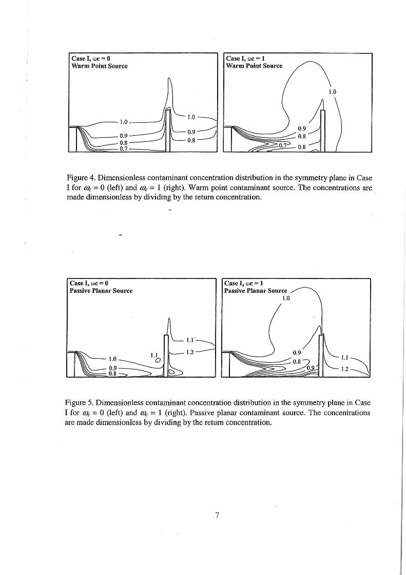
DISCUSSION The flow field in Figure 3 for We = 0
shows a typical displacement ventilation case where the subcooled air enters the room and spreads out radially along the floor due to buoyancy. The main flow direction is horizontal due to the stratification, only close to sources of momentum like the CSP and the walls significant vertical flow is found.
In case of a cooled ceiling with We = 1 we see a different flow pattern. Now, the supply air is almost isothermal and the local flow looks like a typical wall jet assisted by the descending convection currents created along the walls. Due to the removal of heat at the surfaces an increased mixing of the room air takes place and the dominant flow direction is not horizontal anymore. The general velocity level is significantly increased which corresponds well with the measurements reported by Fitzner (1996).
If the contaminant distribution in Figures 4 and 5 are observed significant influence of the cooled ceiling on the contaminant transport in the displacement ventilated room is found. The supply air flow, ranging from a strong buoyant flow to almost isothermal conditions, is also found to influence the air quality experienced by the CSP in the present work.
In Figure 5 the floor is the source of contamination. Here, the results show how the unpolluted air from the inlet device is gradually more and more polluted during the flow throughout the floor. When We = 1 the contaminant transport is highly influenced by the descending currents along the walls.
If the concentration distribution close to the breathing zone is examined a significant influence of the orientation of the person is found. This fact is caused by the combined influence of the entrainment and transport of air along the CSP and the effect

of the CSP acting as an obstacle to the flow field.
The personal exposure of the CSP is presented in Figure 6. It is found that the dimensionless exposure ranges between 0.6 - 0.8 in case of the warm point contaminant source, while in case of the passive planar source the exposure is close to 1.
The effect of me in this numerical case study is relatively weak. Depending on the CSP 01ientation We may both cause an improved as well as a deteriorated indoor air quality.
Measurements by Fitzner and Kri.ihne (1995) show a significant effect at We - 0.6 where the stratified displacement ventilation flow changes into mixing flow. One reason for the discrepancy between the measurements and the present numerical case study may be that the CFD simulation encounters some difficulties in the creation of the significant concentration step-profile in case of me ~ 0, see Figure 2. Another reason for differences may be due to local flow phenomena in the numerical simulations. For instance, the flow from the inlet device which is found to affect the local concentration distribution around the CSP highly.
The influence of the cooled ceiling is modelled in a simple and relatively coarse way in this study. However, the simplified approach represent an easy way to perferm a preliminary examination of the overall influence of a cooled ceiling in an early phase of the design proced1,.1re.
5
REFERENCES Brohus, H. (1997) Personal Exposure to Contaminant Sources in Ventilated Rooms, Ph.D.-thesis, ISSN 0902-7953 R9741, Aalborg University, Dept. of Building Technology and Structural Engineering, Aalborg, Denmark.
Brohus, H. and Nielsen, P. V. (1996) CFD Models of Persons Evaluated by Full-Scale Wind Channel Experiments, Proceedings of Roomvent '96, Vol.2, pp.l37 - 144, Y okohama, Japan,.
Fitzner, K. (1996) Displacement Ventilation and Cooled Ceilings, Results of Laboratory Tests and Practical Installations, Proceedings of Indoor Air '96, Vol. 1, pp. 41-50, Nagoya, Japan.
Fitzner, K. and Kri.ihne, H. (1995) Displacement Flow and Cooled Ceiling, Proceedings of Healthy Buildings '95, Vol. 3, pp. 1187- 1193, Milan, Italy.
Mundt, E. (1996) The Performance of Displacement Ventilation Systems Experimental and Theoretical Studies, Ph.D.-thesis, ISSN 0284 - 141X, ISRN KTH/IT/M--38--SE, Bulletin no 38, Building Services Engineering, Royal Institute of Technology, Stockholm, Sweden.
Patankar, S.V. (1980), Numerical Heat Transfer and Fluid Flow, ISBN 0-89116-522-3, Hemisphere Publishing Corporation.

Case I, We = 0
; : . .
Case I, We= 1
i Reference vector 0.3 rn/s
Figure 3. Vector plots of flow field in Case I for a relative cooling capacity of the cooled ceiling U\: = 0 (top) and We = 1 (bottom). Results from the symmetry plane (z = 0 m) and a horizontal plane 0.1 m above the floor (y = 0.1 m) are shown.
6
Case I, we= 0 Warm Point Source
----- 1.0 ----
'---- 0.9 --o.s---0.7
1.0-----.__
0.9~ 0.8
Case I, we= 1 Warm Point Source
Figure 4. Dimensionless contaminant concentration distribution in the symmetry plane in Case I for me= 0 (left) and me= 1 (right). Warm point contaminant source. The concentrations are made dimensionless by dividing by the return concentration.
Case I, we= 0 Passive Planar Source
Case I, we= 1 Passive Planar Source
1.0
Figure 5. Dimensionless contaminant concentration distribution in the symmetry plane in Case I for me = 0 (left) and me = 1 (right). Passive planar contaminant source. The concentrations are made dimensionless by dividing by the return concentration.
7

1.0
,-.,. 0. 8 -cl d '-' 0.6 ~ r/.1
& 0.4 >< ~ 0.2
CSP Orientation 1
Warm Point Source CSP Orientation 1
-o-Case I
-o-Case II
0.0 +---f----1---f----+---1
0.0 OJ 0.4 0.6 0.8 w c (n.d.)
1.0
1.0
,-.,. 0.8 -cl d '-" 0.6 ~ ::s 8. 0.4
&j 0 .2
Passive Planar Source CSP Orientation 1
-o-Case I
-o-Case II
0.0 +---+---f--i---1-----i
0.0 0.2 0.4 0.6 0.8 1.0 w c (n.d.)
1.0
CSP Orientation 2
Warm Point Source CSP Orientation 2
-o-Case I
-a-Case II
0.0 -1--+--+---+---f---f
0.0 0.2 0.4 0.6 0.8 w c (n.d.)
1.0
1.0
~ 0.8 5 ~ 0.6 r/.1
& 0.4 &j
0.2
Passive Planar Source CSP Orientation 2
-o-Case I
-o-Case II
0.0 +---t--t---t---t----f
0.0 0.2 0.4 0.6 0.8 1.0 w c (n.d.)
Figure 6. Dimensionless personal exposure of the Computer Simulated Person (CSP) versus relative cooling capacity of the cooled ceiling, ale, in case of the warm point source (top) and the passive planar source (bottom). The personal exposure corresponds to the contaminant concentration in the nearest cell along the CSP in a height of 1.5 m. The concentrations are made dimensionless by dividing by the return concentration.
8


l l I
RECENT PAPERS ON INDOOR ENVIRONMENTAL ENGINEERING
PAPER NO. 83: L. Davidson, P.V. Nielsen : A Study of Laminar Backward-Facing Step Flow. ISSN 1395-7953 R9802.
PAPER NO. 84: P.V. Nielsen : Ail11ow in a World Exposition Pavilion Studied by Scale-Model Experiments and Computational Fluid Dynamics. ISSN 1395-7953 R9825.
PAPER NO. 85 : P.V. Nielsen: Stratified Flow in a Room with Displacement Ventilation and Wall-Mounted Air Terminal Devices. ISSN 1395-7953 R9826 .
PAPER NO. 86 : P.V. Nielsen : The Selection of Turbulence Models for Prediction of Room Aililow. ISSN 1395-7953 R9828.
PAPER NO. 87 : K. Svidt, G. Zhang , B. Bjerg : CFO Simulation of Air Velocity Distribution in Occupied Livestock Buildings . ISSN 1395-7953 R9831 .
PAPER NO. 88 : P. V. Nielsen , T. Tryggvason : Computational Fluid Dynamics and Building Energy Peliormance Simulation. ISSN 1395-7953 R9832 .
PAPER NO. 89: K. Svidt, B. Bjerg, S. Morsing , G. Zhang: Modelling of Air Flow through a Slatted Floor by CFO. ISSN 1395-7953 R9833.
PAPER NO. 90 : J.R. Nielsen , P.V. Nielsen , K. Svidt: The Influence of Furniture on Air Velocity in a Roem- An Isothermal Case . ISSN 1395-7953 R9843.
PAPER NO. 91 : P. Lengweiler, J.S. Stn.?Jm , H. Takai , P. Ravn , P.V. Nielsen , A. Maser: Oust Load on Suliaces in Animal Buildings: An Experimental Measuring Method. ISSN 1395-7953 R9844.
PAPER NO. 92 : P. Lengweiler, P.V. Nielsen, A. Maser, P. Heiselberg, H. Takai: Deposition and Resuspension of PaJ1icles: Which Parameters are lmpol1ant? ISSN 1395-7953 R9845.
PAPER NO. 93: C. Topp , P.V. Nielsen , P. Heiselberg , L.E. Sparks , E. M. Howmd, M. Mason : Experiments on Evaporative Emissions in Ventilated Rooms. ISSN 1395-7953 R9835.
PAPER NO. 94 : L. Davidson, P.V. Nielsen: A Study of Low-Reynolds Number Effects in Backward-Facing Step Flow using Large Eddy Simulations. ISSN 1395-7953 R9834.
PAPER NO. 95: A. Nielsen : VRML Programs for Room Ventilation Applications. ISSN 1395-7953 R9846.
PAPER NO. 96: E. Bj0rn , P.V. Nielsen : CFO Simulations of Contaminant Transpo11 between Two Breathing Persons. ISSN 1395-7953 R9809.
PAPER NO. 97: C. Topp , P.V. Nielsen , P. Heiselberg : Modelling Emission from Building Materials with Computational Fluid Dynamics . . ISSN 1395-7953 R99 15.
PAPER NO. 98 : H. Brohus: Influence of a Cooled Ceiling on lndoo1 Air Quality in a Displacement Ventilated Room Examined by Means of Computational Fluid Dynamics. ISSN 1395-7953 R9920.
Complete list of papers: http:ll iee.civil.auc.dk/i6/publ!iee./1tm/

ISSN 1395-7953 R9920
Dept. of Building Technology and Structural Engineering
Aalborg University, September 1999
Sohngaardsholmsvej 57 , DK-9000 Aalborg , Denmark
Phone: +45 9635 8080 Fax: +45 9814 8243
http://iee .civil .auc.dk