aalborg universitet a numerical matrix-based method in
TRANSCRIPT
Aalborg Universitet
A Numerical Matrix-Based method in Harmonic Studies in Wind Power Plants
Dowlatabadi, Mohammadkazem Bakhshizadeh; Hjerrild, Jesper; Kocewiak, ukasz Hubert;Hesselbæk, Bo; Blaabjerg, Frede; Bak, Claus Leth; Wang, Xiongfei; Silva, Filipe Miguel FariadaPublished in:Proceedings of 15th Wind Integration Workshop 2016
Publication date:2016
Document VersionPublisher's PDF, also known as Version of record
Link to publication from Aalborg University
Citation for published version (APA):Dowlatabadi, M. B., Hjerrild, J., Kocewiak, . H., Hesselbæk, B., Blaabjerg, F., Bak, C. L., Wang, X., & Silva, F. M.F. D. (2016). A Numerical Matrix-Based method in Harmonic Studies in Wind Power Plants. In Proceedings of15th Wind Integration Workshop 2016 Energynautics.
General rightsCopyright and moral rights for the publications made accessible in the public portal are retained by the authors and/or other copyright ownersand it is a condition of accessing publications that users recognise and abide by the legal requirements associated with these rights.
- Users may download and print one copy of any publication from the public portal for the purpose of private study or research. - You may not further distribute the material or use it for any profit-making activity or commercial gain - You may freely distribute the URL identifying the publication in the public portal -
Take down policyIf you believe that this document breaches copyright please contact us at [email protected] providing details, and we will remove access tothe work immediately and investigate your claim.

This paper was presented at the 15th Wind Integration Workshop and published in the workshop's proceedings.
A Numerical Matrix-Based method in Harmonic
Studies in Wind Power Plants
Mohammad Kazem Bakhshizadeh, Jesper Hjerrild,
Łukasz Kocewiak, Bo Hesselbæk Electrical System Analysis
DONG Energy Wind Power A/S
Fredericia, Denmark
Email: {modow, jeshj, lukko, bohes }@dongenergy.dk
Frede Blaabjerg, Claus Leth Bak,
Xiongfei Wang, Filipe Faria da Silva Department of Energy Technology
Aalborg University
Aalborg, Denmark
Email: {fbl, clb, xwa, ffs}@et.aau.dk
Abstract— In the low frequency range, there are some
couplings between the positive- and negative-sequence small-
signal impedances of the power converter due to the nonlinear
and low bandwidth control loops such as the synchronization
loop. In this paper, a new numerical method which also
considers these couplings will be presented. The numerical
data are advantageous to the parametric differential
equations, because analysing the high order and complex
transfer functions is very difficult, and finally one uses the
numerical evaluation methods. This paper proposes a
numerical matrix-based method, which is not only able to deal
with those mentioned numerical data, but also it is able to
consider all couplings between the positive and negative
sequences.
Keywords-Harmonic propagation; Harmonic stability;
Resonance; Wind power plant; Wind Turbine Generator.
I. INTRODUCTION
Harmonic emission is inherent to power electronic devices in modern wind power plants [1]–[3]. Even though the power electronic converters offer more efficiency and controllability, they may trigger the parallel and series resonances in the power system [4]. They may also interact with each other or with passive network elements and this might lead to instability [5], [6]. Therefore, the stable and proper operation of the windfarm must be verified for different situations in the design phase using the harmonic analysis methods.
The effects of the outer control loops such as the synchronization and power control loop cannot be neglected in the low frequency range (i.e. around the fundamental frequency). It has been shown that due to the PLL effect there are some couplings between the frequency components [7], [8]. This phenomenon is very important in grids connected via long cables, where the resonances are located at lower frequencies, and if it is neglected it may result in wrong evaluation of system stability. The situation is even worse when the grid and the high voltage grid connection system assets are unbalanced, for instance due to the asymmetrical displacement of the conductors in flat formation underground transmission cables, where there will be more couplings between the frequency components and
consequently finding an analytic solution is very difficult [9], [10].
In this paper a new numerical matrix-based method will be presented that can easily consider all couplings in the impedance model of a power converter. The other advantage is that it uses numerical data instead of very complicated analytic expressions. For instance, the authors in [9] did not show the final expression of the impedance of an unbalanced current controller due to its length. Moreover, the parameters, structure and control of power converters are sometimes confidential, and therefore, the frequency response is only available as a numerical lookup table based on some measurements. Also for some passive elements the numerical representation is less complicated e.g. the grid impedance or the impedance of a long cable [11]. In addition to all above mentioned reasons, finally the numerical evaluation methods such as the Nyquist plot are used for stability assessment. Thus, using numerical data is advantageous.
II. THE PROPOSED METHOD
This method introduces the matrix frequency response definition for all components (active and passive), which can be filled in using the theoretical equations (for the components whose transfer functions are known), the simulation or the experimental data as written in (1). Each column is the frequency spectrum of the response to a sinusoidal excitation.
𝐻 = 𝑅𝑒𝑠𝑝𝑜𝑛𝑠𝑒
𝜔1𝜔2⋮𝜔𝑛
{[
𝐻11(𝑗𝜔) 𝐻12(𝑗𝜔) ⋯ 𝐻1𝑛(𝑗𝜔)
𝐻21(𝑗𝜔) 𝐻22(𝑗𝜔) ⋯ 𝐻2𝑛(𝑗𝜔)⋮ ⋮ ⋱ ⋮
𝐻𝑛1(𝑗𝜔) 𝐻𝑛2(𝑗𝜔) ⋯ 𝐻𝑛𝑛(𝑗𝜔)
]
⏟
𝜔1 𝜔2 ⋯ 𝜔𝑛𝐸𝑥𝑐𝑖𝑡𝑎𝑡𝑖𝑜𝑛
(1)
where Hij is the frequency component of the response at ω=ωi to a sinusoidal excitation with a frequency at ω=ωj. For a Linear-Time-Invariant (LTI) system there is only one response at the same frequency of the excitation, therefore,
This project is supported in part by DONG Energy Wind Power and in part by Innovation Fund Denmark.

the matrix frequency response can be written as (2), in which off-diagonal elements are zero.
𝐻𝐿𝑇𝐼 = 𝑅𝑒𝑠𝑝𝑜𝑛𝑠𝑒
𝜔1𝜔2⋮𝜔𝑛
{[
𝐻(𝑗𝜔1) 0 ⋯ 0
0 𝐻(𝑗𝜔2) ⋯ 0⋮ ⋮ ⋱ ⋮0 0 ⋯ 𝐻(𝑗𝜔𝑛)
]
⏟
𝜔1 𝜔2 ⋯ 𝜔𝑛𝐸𝑥𝑐𝑖𝑡𝑎𝑡𝑖𝑜𝑛
(2)
Fig. 1 (a) shows a balanced current controlled converter, which is considered in this paper. Fig. 1 (b) shows the current control strategy in the dq domain and Fig. 1 (c) is a simple Synchronous Reference Frame PLL (SRF-PLL), which is used in this paper. The admittance matrix of this converter in the sequence domain has been obtained in [7], and as it has been mentioned in [9] that the negative sequence component is in fact the complex conjugate of a positive sequence quantity with the negated frequency. Therefore, the new small-signal admittance matrix is (4).
𝑍𝑛𝑒𝑔(𝑗𝜔) = (𝑍𝑝𝑜𝑠(−𝑗𝜔))∗ (3)
𝑌𝑃𝑁 = [𝑌𝑝(𝑠) (𝐽𝑝(−𝑠 − 2𝑗𝜔1))
∗
𝐽𝑃(𝑠) (𝑌𝑝(−𝑠 − 2𝑗𝜔1))∗] (4)
𝑌𝑝(𝑠)
=1 − 𝑉𝑑𝑐𝑇𝐹𝑃𝐿𝐿(𝑠 − 𝑗𝜔1) (𝐶𝑑𝑞 + 𝐼𝑑𝑞𝐻𝑖(𝑠 − 𝑗𝜔1))
𝐿𝑠 + 𝑉𝑑𝑐𝐻𝑖(𝑠 − 𝑗𝜔1)
(5)
𝐽𝑝(𝑠) =𝑉𝑑𝑐𝑇𝐹𝑃𝐿𝐿(𝑠 − 𝑗𝜔1) (𝐶𝑑𝑞
∗ + 𝐼𝑑𝑞∗ 𝐻𝑖(𝑠 − 𝑗𝜔1))
𝐿(𝑠 − 2𝑗𝜔1) + 𝑉𝑑𝑐𝐻𝑖(𝑠 − 𝑗𝜔1) (6)
where Hi(s)=Kp+Ki/s is a Proportional-Integral (PI) regulator transfer function for both d and q current components, TFPLL(s) is the PLL transfer function, Cdq are the steady state values of the duty ratios in the dq domain, and Idq are the current setpoints in the dq domain.
Fig. 2 shows the self-admittance term (YP(s)) and the coupling admittance term (JP(s)) as a function of frequency for a converter with the parameters listed in Table I. It can be seen that in the low frequency range, the coupling term, which is caused by the PLL, is not negligible.
Fig. 3 shows the small-signal admittance matrix for a balanced converter as shown in Fig. 1, which is linearized around the operating point listed in Table I. The horizontal axis is the excitation frequency, the vertical axis is the response frequency and the color intensity shows the response magnitude. The negative frequency is to model the negative sequence component. It must be noted that the admittance matrix is a complex matrix, however for the sake of simplicity; only the magnitude is shown here. It can clearly be seen that there are some couplings between the positive- and negative-sequence admittances. For instance in
PLLCurrent
Controldqabc
PWM
Idqr
θPLL
dqabc
GridZg(s)=sLg+RgsL
θPLL
idqcdq
Vdc
PCC
vabciabc
(a)
Hi(s)
Hi(s)
+
+
cd
cq
Idr
Iqr
id
iq
HPLL(s) dqabc
vdqθPLL
vabc
(b) (c) Fig. 1. A current controlled three-phase converter. (a) Connection to the grid.
(b) Current controllers in the dq frame. (c) A SRF-PLL block.
TABLE I. THE PARAMETERS OF THE CONSIDERED CONVERTER
Symbol Description Value
Vg Grid line-ground peak voltage 90 V
f1 Grid frequency 50 Hz
Lg Grid inductance 3 mH
Rg Grid equivalent resistance 0.5 Ω
Vdc Inverter dc voltage 300 V
Idr d channel current reference 7 A
Iqr q channel current reference 0 A
Kp Proportional gain of the current controller 0.01
Ki Integrator gain of current controller 3
BWPLL Bandwidth of PLL (Stable) 50 Hz
(Unstable) 70 Hz
fs Sampling frequency 5 kHz
fsw Switching frequency 5 kHz
Fig.2. Self- and coupling-admittances of the converter as a function of
frequency.
Fig. 3. Admittance matrix of the converter.

response to a 350-Hz-positive-sequence voltage perturbation, the converter current also has a 250-Hz-negative-sequence current.
A. How to Fill in the Admittance Matrix
In the previous section, it is shown that if the analytic expressions for the elements are available then the matrix can be simply filled in by calculating the expression at different frequencies; however, the analytic equations are not always available. Then, for each frequency excitation the frequency spectrum of the measured response must be extracted and be put in the corresponding location in the admittance matrix. The measurements can be obtained using by either simulating the element in a circuit simulator or experiments. Fig. 4 shows the current response of a power converter to a positive-sequence perturbation at 450 Hz, which is obtained by experiments on a low power prototype of current controlled inverter. By doing the Fourier analysis it can be seen that there is a positive-sequence current at 450 Hz and a negative-sequence current at 350 Hz.
B. Dependency on the operating point
One may ask that if the considered system is nonlinear and if small signal linearization technique is used it is only valid around the operating point. In other words, if the operating point (i.e. the output power of the converter) is changed then these models are not valid any longer. Fortunately, the small-signal admittance of the power converter changes linearly when there is a change in the operating point. From (5) and (6) it can be seen that the small-signal admittance is a linear function of the output current Idq and the converter duty ratio Cdq, which has a linear relationship with the PCC voltage. Fig. 5 verifies the linear behavior for the considered current controller. By knowing that dependency on the operating point is linear, the admittance of the converter at different operating points can be derived by
𝑌(𝑉𝑑𝑞 + ∆𝑉𝑑𝑞 , 𝐼𝑑𝑞 + ∆𝐼𝑑𝑞)
= 𝑌(𝑉𝑑𝑞 , 𝐼𝑑𝑞) +𝜕𝑌
𝜕𝑉𝑑𝑞∆𝑉𝑑𝑞
+𝜕𝑌
𝜕𝐼𝑑𝑞∆𝐼𝑑𝑞
(7)
The partial derivatives in (7) can easily be found by the procedure illustrated in Fig. 6. For instance, by repeating the simulation for another current set point while all other quantities (PCC voltage, current control parameters and etc.) are kept constant, the rate of the change in the admittance to
a change in the current 𝜕𝑌
𝜕𝐼𝑑𝑞 can be found.
III. SIMULATION RESULTS
This section shows how the admittance matrix can be utilized for the harmonic studies including the harmonic emission and stability studies.
A. Harmonic emission studies
The admittance/impedance matrices can simply be used like normal admittances/impedances to find the harmonics at the PCC voltage or the injected current (see Fig. 7). The PCC voltage can be found by calculating the voltage
(a)
(b)
Fig. 4. Experimental results of the Current response to a voltage perturbation at 450 Hz. (a) Current waveform in time domain. (b)
Frequency components of the output current in a phasor diagram.
(a)
(b)
Fig. 5. The linear relationship between the small-signal admittances and the operating point. (a) The admittance changes linearly by a change in the current set point. (b) The admittance changes linearly by a change in the PCC voltage.
Run without perturbation
Set fp=fpiStartRun at the
operating pointChange rated
current
Change PCC voltagei=i+1Finished?end
Yes
Fig.6. A flowchart showing how to fill in the admittance matrix.
GridZg(s)=sLg+RgsL
Vdc
PCC
Background
Harmonic
Fig. 7. Harmonic emission studies.
division between the grid impedance and converter admittance as
𝑉𝑃𝐶𝐶 =𝑍𝐶
𝑍𝑔 + 𝑍𝑐𝑉𝑔 (8)
The same can be done using matrix impedances
[𝑉𝑃𝐶𝐶] = [𝑍𝑐][𝑍𝑔 + 𝑍𝑐]−1[𝑉𝑔] (9)
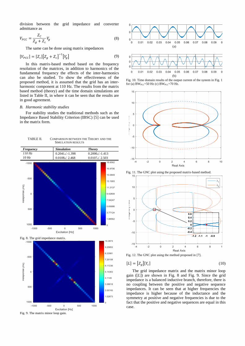
In this matrix-based method based on the frequency resolution of the matrices, in addition to harmonics of the fundamental frequency the effects of the inter-harmonics can also be studied. To show the effectiveness of the proposed method, it is assumed that the grid has an inter-harmonic component at 110 Hz. The results from the matrix based method (theory) and the time domain simulations are listed in Table II, in where it can be seen that the results are in good agreement.
B. Harmonic stability studies
For stability studies the traditional methods such as the Impedance Based Stability Criterion (IBSC) [5] can be used in the matrix form.
[𝐿] = [𝑍𝑔][𝑌𝑐] (10)
The grid impedance matrix and the matrix minor loop gain ([L]) are shown in Fig. 8 and Fig. 9. Since the grid impedance is a balanced inductive branch, therefore, there is no coupling between the positive and negative sequence impedances. It can be seen that at higher frequencies the impedance is higher because of the inductance and the symmetry at positive and negative frequencies is due to the fact that the positive and negative sequences are equal in this case.
TABLE II. COMPARISON BETWEEN THE THEORY AND THE
SIMULATION RESULTS
Frequency Simulation Theory
110 Hz 0.2041-1.398 0.2000-1.413
10 Hz 0.0108 2.468 0.0107 2.503
Fig. 8. The grid impedance matrix.
Fig. 9. The matrix minor loop gain.
(a)
(b)
Fig. 10. Time domain results of the output current of the system in Fig. 1 for (a) BWPLL=50 Hz (c) BWPLL=70 Hz.
Fig. 11. The GNC plot using the proposed matrix-based method.
Fig. 12. The GNC plot using the method proposed in [7].

The minor loop gain in this case is a matrix; therefore the Generalized Nyquist Criterion (GNC) should be used [12], which is indeed the plot of the eigenvalues of [L]. Fig. 11 shows the GNC plot of the matrix minor loop gain for a PLL bandwidth of 70 Hz. It can be seen that it encircles the critical point and the time domain simulations as shown in Fig. 10 also verify that for this PLL bandwidth the system is unstable. The interesting point is that this figure is almost the same as the results obtained in [7], in which the matrix method has not been used (see Fig. 12).
IV. CONCLUSION
In this paper, a numerical matrix-based method for harmonic studies is proposed. The method is able to deal with the couplings between the positive and negative sequence impedances. This happens when the low frequency outer loop dynamics such as the PLL and dc link control are considered and/or the transmission network is unbalanced. This method can be used in both harmonic propagation and stability studies. Because this method uses matrix notation with a desired frequency resolution, even the effects of the inter-harmonics can be considered. The results of the stability evaluation is almost the same as the results obtained in the previous works [7], but if the imbalance is considered the previous methods cannot find the solution due to the increased number of couplings but this method is able to find the solution since it uses matrix notations. The application of this method for the unbalanced systems is the future work of the authors.
REFERENCES
[1] P. Brogan, “The stability of multiple, high power, active front end voltage sourced converters when connected to wind farm collector systems,” Proc. EPE Wind Energy Chapter Semin. 2010.
[2] Ł. Kocewiak, S. Chaudhary, and B. Hesselbæk, “Harmonic Mitigation Methods in Large Offshore Wind Power Plants,” in The 12th International Workshop on Large-Scale Integration of Wind
Power into Power Systems as well as Transmission Networks for Offshore Wind Farms, 2013, pp. 443–448.
[3] Ł. H. Kocewiak, J. Hjerrild, and C. L. Bak, “Wind turbine converter control interaction with complex wind farm systems,” IET Renew. Power Gener., vol. 7, no. 4, pp. 380–389, Jul. 2013.
[4] Z. Shuai, D. Liu, J. Shen, C. Tu, Y. Cheng, and A. Luo, “Series and Parallel Resonance Problem of Wideband Frequency Harmonic and Its Elimination Strategy,” IEEE Trans. Power Electron., vol. 29, no. 4, pp. 1941–1952, Apr. 2014.
[5] J. Sun, “Impedance-based stability criterion for grid-connected inverters,” IEEE Trans .Power Electron., vol. 26, no. 11, pp. 3075-3078, Nov. 2011.
[6] X. Wang, F. Blaabjerg, and W. Wu, “Modeling and Analysis of Harmonic Stability in an AC Power-Electronics-Based Power System,” IEEE Trans. Power Electron., vol. 29, no. 12, pp. 6421-6432, Dec. 2014.
[7] M. K. Bakhshizadeh, X. Wang, F. Blaabjerg, J. Hjerrild, L. Kocewiak, C. L. Bak, and B. Hesselbek, “Couplings in Phase Domain Impedance Modelling of Grid-Connected Converters,” IEEE Trans. Power Electron., vol. 31, no. 10, pp. 6792 – 6796, Oct. 2016.
[8] A. Rygg, M. Molinas, Z. Chen, and xu cai, “A modified sequence domain impedance definition and its equivalence to the dq-domain impedance definition for the stability analysis of AC power electronic systems,” IEEE J. Emerg. Sel. Top. Power Electron., vol.PP, no.99, pp.1-1.
[9] M. K. Bakhshizadeh, J. Hjerrild, L. Kocewiak, B. Hesselbaek, X. Wang, F. Blaabjerg, and C. L. Bak, “Small-signal model of a decoupled double synchronous reference frame current controller,” in 2016 IEEE 17th Workshop on Control and Modeling for Power Electronics (COMPEL), 2016, pp. 1–6.
[10] C. F. Jensen, Ł. H. Kocewiak, Z. Emin, "Amplification of Harmonic Background Distortion in Wind Power Plants with Long High Voltage Connections," CIGRE Biennial Session, CIGRÉ, 21-26 August 2016, Paris, France, C4-112.
[11] M. K. Bakhshizadeh, F. Blaabjerg, C. Leth Bak, F. Faria da Silva, J. Hjerrild, K. Lukasz, B. Hesselbaek, and T. Sørensen, “Harmonic Modelling, Propagation and Mitigation for Large Wind Power Plants Connected via Long HVAC Cables: Review and Outlook of Current Research,” in IEEE ENERGYCON 2016, pp. 1-6.
[12] B. Wen, D. Boroyevich, R. Burgos, P. Mattavelli, and Z. Shen, “Analysis of D-Q Small-Signal Impedance of Grid-Tied Inverters,” IEEE Trans. Power Electron., vol. 31, no. 1, pp. 675–687, Jan. 2016.