a4 storm - schwarzeschwarze.com/2014 manuals/2014 a4 storm/a4 storm ops pub... · 2014-07-08 ·...
TRANSCRIPT

© 2014 Alamo Group Inc. $0.00
Sweeper
A4 STORM
Schwarze Industries, Inc.1055 Jordan RoadHuntsville, AL 35811-93101-800-879-7933Email: [email protected]: www.schwarze.com
Published 09/13 Version 1.0, 09/13
OPERATOR’S MANUAL
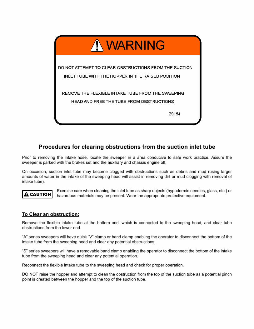
Procedures for clearing obstructions from the suction inlet tube
Prior to removing the intake hose, locate the sweeper in a area conducive to safe work practice. Assure thesweeper is parked with the brakes set and the auxiliary and chassis engine off.
On occasion, suction inlet tube may become clogged with obstructions such as debris and mud (using largeramounts of water in the intake of the sweeping head will assist in removing dirt or mud clogging with removal ofintake tube).
Exercise care when cleaning the inlet tube as sharp objects (hypodermic needles, glass, etc.) orhazardous materials may be present. Wear the appropriate protective equipment.
To Clear an obstruction:
Remove the flexible intake tube at the bottom end, which is connected to the sweeping head, and clear tubeobstructions from the lower end.
“A” series sweepers will have quick “V” clamp or band clamp enabling the operator to disconnect the bottom of theintake tube from the sweeping head and clear any potential obstructions.
“S” series sweepers will have a removable band clamp enabling the operator to disconnect the bottom of the intaketube from the sweeping head and clear any potential operation.
Reconnect the flexible intake tube to the sweeping head and check for proper operation.
DO NOT raise the hopper and attempt to clean the obstruction from the top of the suction tube as a potential pinchpoint is created between the hopper and the top of the suction tube.

A4 StormInformation Sheet
DELIVERY DATE __________________________
COMPANY NAME __________________________
ADDRESS __________________________
CITY __________________________
STATE _____________ZIP__________
PHONE (_____)____________________
CHASSIS TYPE _________________________
CHASSIS SERIAL NO. _________________________
SWEEPER SERIAL NUMBER _________________________
POWER MODULE ENGINE TYPE _________________________
POWER MODULE ENGINE SERIAL NO. _________________________
HYDRAULIC PUMP TYPE _________________________
BEACON TYPE _________________________
GUTTER BROOM MOTOR TYPE _________________________
PRESSURIZED WATER SYSTEM PUMP TYPE _________________________
JOB NO. _________________________
Delivery Record File Copy.
Remove This Page Prior ToDelivery To Customer.
MANUFACTURED BY:
Schwarze Industries, Inc.1055 Jordan RoadHuntsville, AL 35811-93101-800-879-7933Email: [email protected]: http://schwarze.com
SOLD AND SERVICED BY:

A4 StormInformation Sheet
DELIVERY DATE __________________________
COMPANY NAME __________________________
ADDRESS __________________________
CITY __________________________
STATE ________________ZIP_______
PHONE (_____) ___________________
CHASSIS TYPE _________________________
CHASSIS SERIAL NO. _________________________
SWEEPER SERIAL NUMBER _________________________
POWER MODULE ENGINE TYPE _________________________
POWER MODULE ENGINE SERIAL NO. _________________________
HYDRAULIC PUMP TYPE _________________________
BEACON TYPE _________________________
GUTTER BROOM MOTOR TYPE _________________________
PRESSURIZED WATER SYSTEM PUMP TYPE _________________________
JOB NO. _________________________
IMPORTANTCUSTOMER
INFORMATION
It is important that allwarranty forms for thechassis, sweeper, andauxiliary engine be filled outand sent to the appropriatecomponent manufacturer.Failure to do so may resultin costly delay or denialshould a warranty claim bemade.
MANUFACTURED BY:
Schwarze Industries, Inc.1055 Jordan RoadHuntsville, AL 35811-93101-800-879-7933Email: [email protected]: http://schwarze.com
SOLD AND SERVICED BY:
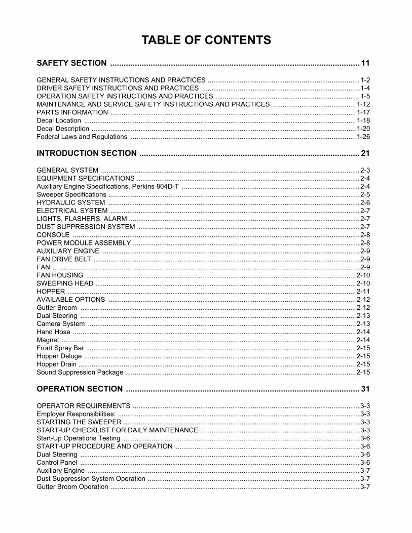
TABLE OF CONTENTS
SAFETY SECTION ............................................................................................................... 11
GENERAL SAFETY INSTRUCTIONS AND PRACTICES .................................................................................1-2DRIVER SAFETY INSTRUCTIONS AND PRACTICES ....................................................................................1-4OPERATION SAFETY INSTRUCTIONS AND PRACTICES .............................................................................1-5MAINTENANCE AND SERVICE SAFETY INSTRUCTIONS AND PRACTICES ............................................1-12PARTS INFORMATION ...................................................................................................................................1-17Decal Location .................................................................................................................................................1-18Decal Description .............................................................................................................................................1-20Federal Laws and Regulations ........................................................................................................................1-26
INTRODUCTION SECTION .................................................................................................. 21
GENERAL SYSTEM ..........................................................................................................................................2-3EQUIPMENT SPECIFICATIONS .......................................................................................................................2-4Auxiliary Engine Specifications, Perkins 804D-T ...............................................................................................2-4Sweeper Specifications ......................................................................................................................................2-5HYDRAULIC SYSTEM ......................................................................................................................................2-6ELECTRICAL SYSTEM .....................................................................................................................................2-7LIGHTS, FLASHERS, ALARM ...........................................................................................................................2-7DUST SUPPRESSION SYSTEM ......................................................................................................................2-7CONSOLE .........................................................................................................................................................2-8POWER MODULE ASSEMBLY .........................................................................................................................2-8AUXILIARY ENGINE .........................................................................................................................................2-9FAN DRIVE BELT ..............................................................................................................................................2-9FAN ....................................................................................................................................................................2-9FAN HOUSING ................................................................................................................................................2-10SWEEPING HEAD ...........................................................................................................................................2-10HOPPER ..........................................................................................................................................................2-11AVAILABLE OPTIONS ....................................................................................................................................2-12Gutter Broom ...................................................................................................................................................2-12Dual Steering ...................................................................................................................................................2-13Camera System ...............................................................................................................................................2-13Hand Hose .......................................................................................................................................................2-14Magnet .............................................................................................................................................................2-14Front Spray Bar ................................................................................................................................................2-15Hopper Deluge .................................................................................................................................................2-15Hopper Drain ....................................................................................................................................................2-15Sound Suppression Package ...........................................................................................................................2-15
OPERATION SECTION ........................................................................................................ 31
OPERATOR REQUIREMENTS .........................................................................................................................3-3Employer Responsibilities: .................................................................................................................................3-3STARTING THE SWEEPER ..............................................................................................................................3-3START-UP CHECKLIST FOR DAILY MAINTENANCE .....................................................................................3-3Start-Up Operations Testing ..............................................................................................................................3-6START-UP PROCEDURE AND OPERATION ..................................................................................................3-6Dual Steering .....................................................................................................................................................3-6Control Panel .....................................................................................................................................................3-6Auxiliary Engine .................................................................................................................................................3-7Dust Suppression System Operation .................................................................................................................3-7Gutter Broom Operation .....................................................................................................................................3-7

Hand Hose Operation ........................................................................................................................................3-8Magnet Operation ..............................................................................................................................................3-8Camera System Operation ................................................................................................................................3-8SWEEPING ........................................................................................................................................................3-9Sweeping Condition Control ..............................................................................................................................3-9SHUTTING DOWN THE SWEEPER ...............................................................................................................3-10DUMPING THE HOPPER ................................................................................................................................3-10END OF SHIFT CLEANUP / MAINTENANCE .................................................................................................3-11QUICK REFERENCE OPERATING GUIDELINE ............................................................................................3-12SWEEPING ACCESSORIES ...........................................................................................................................3-13TROUBLESHOOTING GUIDE ........................................................................................................................3-14Sweeper ...........................................................................................................................................................3-14Sweeper Engine ...............................................................................................................................................3-15Automatic Shutdown System ...........................................................................................................................3-15Dust Suppression System ................................................................................................................................3-15Other Symptoms ..............................................................................................................................................3-16Hydraulic System .............................................................................................................................................3-16Gutter Broom ...................................................................................................................................................3-17
MAINTENANCE SECTION ................................................................................................... 41
PARTS INFORMATION .....................................................................................................................................4-2GENERAL MAINTENANCE ...............................................................................................................................4-2Maintenance Logs ..............................................................................................................................................4-2Maintenance Schedules .....................................................................................................................................4-3CLEANING .........................................................................................................................................................4-4SWEEPER FLUID MAINTENANCE ..................................................................................................................4-4Auxiliary Engine Oil ............................................................................................................................................4-4Auxiliary Engine Cooling System .......................................................................................................................4-4Hydraulic System ...............................................................................................................................................4-5LUBRICATION SCHEDULE ..............................................................................................................................4-5FILTERS ............................................................................................................................................................4-6Auxiliary Engine Filters ......................................................................................................................................4-6Hydraulic Tank Filters ........................................................................................................................................4-6SEALS ...............................................................................................................................................................4-7Seal Replacement ..............................................................................................................................................4-7HOPPER ............................................................................................................................................................4-7AUXILIARY ENGINE .........................................................................................................................................4-8DRIVETRAIN COMPONENT MAINTENANCE ..................................................................................................4-8Drive Belt Tension Adjustment ...........................................................................................................................4-8Drive Belt Replacement .....................................................................................................................................4-9Fan Shaft Bearing Lubrication .........................................................................................................................4-10Fan Shaft Bearing Replacement ......................................................................................................................4-11FAN HOUSING ................................................................................................................................................4-12Fan Housing Check .........................................................................................................................................4-12Fan Replacement .............................................................................................................................................4-13Fan Housing Liner Replacement .....................................................................................................................4-15SWEEPING HEAD ...........................................................................................................................................4-16Skid Plate Adjustment / Replacement ..............................................................................................................4-16Sweeping Head Tension Spring Adjustment ...................................................................................................4-17Sweeping Head Flap Check/Replacement ......................................................................................................4-18Sweeping Head Hose Replacement ................................................................................................................4-20Sweeping Head Hose Rotation ........................................................................................................................4-20GUTTER BROOM ............................................................................................................................................4-20Gutter Broom Pattern Check ............................................................................................................................4-20Gutter Broom Tilt Adjustment ...........................................................................................................................4-21Gutter Broom Extension Spring Adjustment ....................................................................................................4-22

Gutter Broom Cylinder Adjustment / Replacement ..........................................................................................4-23Gutter Broom Motor Replacement ...................................................................................................................4-24Gutter Broom Tilt Cylinder Replacement .........................................................................................................4-25Gutter Broom Bristles Replacement ................................................................................................................4-25HYDRAULIC SYSTEM MAINTENANCE .........................................................................................................4-26Hydraulic Tank Fill-Up ......................................................................................................................................4-26Draining the Hydraulic Tank .............................................................................................................................4-27Hydraulic Fluid Change ....................................................................................................................................4-27Hydraulic Suction Strainer ...............................................................................................................................4-28Hydraulic Return Filter .....................................................................................................................................4-28Hydraulic System Pressure Check/Adjustment ...............................................................................................4-29Gutter Broom Hydraulic Adjustment ................................................................................................................4-30DUST SUPPRESSION SYSTEM MAINTENANCE .........................................................................................4-31Water Reservoir Refill ......................................................................................................................................4-31Water Manifold Solenoid Cleaning ...................................................................................................................4-32‘Y’ Strainer Cleaning/Replacement ..................................................................................................................4-33Water Pump Maintenance ...............................................................................................................................4-33Water Pump Pressure Check ..........................................................................................................................4-34Water Nozzle Cleaning/Replacement ..............................................................................................................4-34Dust Suppression System Winterizing .............................................................................................................4-35


Safety Section 1-1
© 2014 Alamo Group Inc.
SAFETY SECTION

SAFETYS
AF
ET
Y
GENERAL SAFETY INSTRUCTIONS AND PRACTICES
A careful operator is the best operator. Safety is of primary importance to the manufacturer and should be tothe owner/operator. Most accidents can be avoided by being aware of your equipment, your surroundings, andobserving certain precautions. The first section of this manual includes a list of Safety Messages that, iffollowed, will help protect the operator and bystanders from injury or death. Read and understand these SafetyMessages before assembling, operating or servicing this Implement. This equipment should only be operatedby those persons who have read the manual, who are responsible and trained, and who know how to do soresponsibly.
The Safety Alert Symbol combined with a Signal Word, as seen below, is used throughout thismanual and on decals which are attached to the equipment. The Safety Alert Symbol means:“ATTENTION! BECOME ALERT! YOUR SAFETY IS INVOLVED!” The Symbol and Signal Wordare intended to warn the owner/operator of impending hazards and the degree of possible injuryfaced when operating this equipment.
Indicates an imminently hazardous situation that, if not avoided, WILL result in DEATH ORVERY SERIOUS INJURY.
Indicates an imminently hazardous situation that, if not avoided, COULD result in DEATHOR SERIOUS INJURY.
Indicates an imminently hazardous situation that, if not avoided, MAY result in MINORINJURY.
Identifies special instructions or procedures that, if not strictly observed, could result indamage to, or destruction of the machine, attachments or the environment.
NOTE: Identifies points of particular interest for more efficient and convenient operation or repair.(SG-1)
Practice all usual and customary safe working precautions and above all---remember safety isup to YOU. Only YOU can prevent serious injury or death from unsafe practices.
READ, UNDERSTAND, and FOLLOW the following Safety Messages. Serious injury ordeath may occur unless care is taken to follow the warnings and instructions stated in theSafety Messages. Always use good common sense to avoid hazards. (SG-2)
Si no lee ingles, pida ayuda a alguien que si lo lea para que le traduzca lasmedidas de seguridad. (SG-3)
A4 Storm 09/13 Safety Section 1-2
© 2014 Alamo Group Inc.

SAFETYS
AF
ET
Y
Never operate the Sweeper until you have read and completelyunderstand this Manual, the Truck Operator’s Manual, the AuxiliaryEngine Operator’s manual, and each of the Safety Messages found inthese Manuals and those affixed to the Sweeper and its components.Learn how to stop the Sweeper’s engines suddenly in an emergency.Never allow inexperienced or untrained personnel to operate the Truckand Sweeper without supervision. Make sure the operator has fully readand understood the manuals prior to operation. (SWG-4)
In addition to the design and configuration of this Sweeper, including Safety Signs and Safety Equipment,hazard control and accident prevention are dependent upon the awareness, concern, prudence, and propertraining of personnel involved in the operation, transport, maintenance, and storage of the machine. Referalso to Safety Messages and operation instruction in each of the appropriate sections of the Truck andAuxiliary Engine Manuals. Pay close attention to the Safety Signs affixed to the Sweeper. (SWG-5)
Always maintain the safety decals in good readable condition. If the decals are missing,damaged, or unreadable, obtain and install replacement decals immediately. Consult yourauthorized sales representative for decal replacements. (SWS-1)
All Safety Shields, Guards and other Protective Safety devices should be used andmaintained in good working condition. All safety devices should be inspected carefully atleast daily for missing or broken components. NEVER REMOVE PROTECTIVE SHIELDSAND GUARDS! NEVER MODIFY OR CUT PROTECTIVE SHIELDS OR GUARDS!When shields or guards are removed to access areas for maintenance, they must bereplaced and be in good condition before operating. Missing, broken, or worn shields,guards, and other protective devices must be replaced at once and prior to operation toreduce the possibility of injury or death from thrown objects, entanglement, or contact. (SWS-2)
The Sweeper must be equipped with a fire extinguisher, rated for all fires, in an accessibleand visible area. The fire extinguisher should be inspected routinely by a certified inspectorfor operational use and replaced as needed. Never obstruct access to the fire extinguisher.(SWS-6)
A4 Storm 09/13 Safety Section 1-3
© 2014 Alamo Group Inc.

SAFETYS
AF
ET
Y
DRIVER SAFETY INSTRUCTIONS AND PRACTICES
Repeated or substantial breathing of hazardous dusts, includingcrystalline silica, could cause fatal or serious respiratory disease includingsilicosis. Concrete, masonry, many types of rock, and various othermaterials contain silica sand. California lists respirable crystalline silica asa substance known to cause cancer. Operation of this equipment undercertain conditions may generate airborne dust particles that could containcrystalline silica. In those conditions, personal protective equipmentincluding an appropriate respirator must be used. If excessive dust isgenerated, a dust collection or suppression system should also be usedduring operation. (SG-41)
The operator of the Sweeper must be trained in the operation and safe use of this machine.The operator must read and completely understand the operator’s manuals of the Sweeper,Truck and Auxiliary engine manufacturers. New operators should be trained in an openarea clear of obstructions before operating on public roadways. If operation of the entireSweeper unit (Truck, Auxiliary engine, and Sweeping Components) is not completelyunderstood, consult your authorized sales representative for a detailed explanation. Neverallow an untrained or unqualified driver to operate the Sweeper. (SWD-01)
The Sweeper driver must meet the requirements and possess a Motor Vehicle License asdetermined by the state in which the Sweeper is operated if used on public roadways.Contact your local State Department of Public Safety office for special licensingrequirements to operate the Sweeper in your area. (SWD-2)
NEVER use drugs or alcohol immediately before or while driving oroperating the Sweeper. Drugs and alcohol will affect an operator’salertness and coordination and therefore affect the operator’s ability tooperate the Sweeper safely. Before operating the Sweeper,an operator on prescription or over-the-counter medicationmust consult a medical professional regarding any sideeffects of the medication that would hinder their ability tooperate the Sweeper safely. NEVER knowingly allow anyoneto operate this Sweeper when their alertness or coordinationis impaired. Serious injury or death to the operator or otherscould result if the operator is under the influence of drugs oralcohol. (SWD-3)
A4 Storm 09/13 Safety Section 1-4
© 2014 Alamo Group Inc.

SAFETYS
AF
ET
Y
OPERATION SAFETY INSTRUCTIONS AND PRACTICES
Always wear OSHA approved Personal Protective Equipment (PPE) while operating,servicing, repairing, and/or cleaning the Sweeper. PPE is designed to provide bodilyprotection during such activities.
Personal Protective Equipment includes:
• Protective Eye Wear• Steel Toed Safety Footwear• Gloves• Hearing Protection• Close Fitted Clothing• Hard Hat-When working around a raised hopper.• Respirator-Depending on conditions and material being swept or cleaned.Specialized protective equipment may be required if dangerous or hazardous material is being swept by orcleaned from the Sweeper. (SWD-4)
Prolonged operation of the Sweeper may cause operator boredom and/or fatigue affectingthe safe operation of the Sweeper. It is recommended that the operator take scheduledwork breaks to help prevent these potentially impaired operating conditions. If possible,completely shut down the Sweeper, exit the cab and move around stretching your arms andlegs. Never operate the Sweeper in a fatigued or bored mental state that impairs properand safe Sweeper operation. (SWD-5)
PROLONGED EXPOSURE TO LOUD NOISE MAY CAUSEPERMANENT HEARING LOSS! Sweeper operation can often benoisy enough to cause permanent hearing loss. We recommend thatyou always wear hearing protection if the noise in the Operator’sposition exceeds 80db. Noise over 85db over an extended period oftime will cause severe hearing loss. Noise over 90db adjacent to theOperator over an extended period of time will cause permanent or totalhearing loss. Note: Hearing loss from loud noise [from sweepers,chain saws, radios, and other such sources close to the ear] iscumulative over a lifetime without hope of natural recovery. (SWD-6)
Do not operate, or perform maintenance to, the Sweeper while wearing loose fittingclothing. Entanglement of loose clothing with the rotating elements can result in seriousinjury or death. Stay clear of all rotating elements at all times. (SWD-7)
Use both hands for support when getting on and off the Sweeper. Use handholds andsteps on the Sweeper for support when boarding the Sweeper. Never use the Sweepercontrol levers for support when boarding the sweeper. (SWO-1)
A4 Storm 09/13 Safety Section 1-5
© 2014 Alamo Group Inc.

SAFETYS
AF
ET
Y
Use available Sweeper handholds and steps to exit the Sweeper. Make sure you havesolid footing before stepping down. Be careful of your step and use extra caution whenmud, ice, snow, or other matter has accumulated on the steps or handrails. Never rush toexit or jump off the Sweeper. (SWO-2)
Do not attempt to mount the Sweeper or Truck while the machine is moving.Never attempt to mount a runaway Sweeper. Serious injury or death mayoccur from being run over by a moving Sweeper. (SWO-3)
BEFORE leaving the Truck’s seat, always engage the parking brake and/or set the Truck’stransmission in parking gear, stop the engine, remove the key, and wait for all moving partsto stop. Never dismount a Truck that is moving or while the Truck and Auxiliary enginesare running. Operate the Sweeper controls from the Truck seat only. (SWO-4)
Always wear a seat belt while driving the Sweeper during operation andtransport. Serious injury or even death could result from fall ing out of theTruck or from being involved in a collision. (SWO-5)
Start the Truck and Auxiliary engine only when seated and belted in theTruck’s operator seat. Operate the Sweeper controls only while properlyseated with the seat belt secured around you. Inadvertent movement of theTruck and/or Sweeper components may cause serious injury or death to theoperator and passersby. Read the Truck and Auxiliary Engine operator ’smanuals for proper starting instructions. (SWO-6)
Use the right side steering only for sweeping, and never while exceeding 15 MPH. Fortravel, the Sweeper must be driven from the LEFT side, unless sweeper is only equippedwith right side steering and controls. If the Sweeper is to be operated from the right handside, make sure the Sweeper’s mirrors are aligned for visibility from the right hand sidesteering position. (SWO-37)
Sweep only in conditions where you have clear visibility of the area being swept in daylightor with adequate artificial lighting. Never sweep in darkness of foggy conditions where youcannot clearly see at least 50 feet in front and to the sides of the Sweeper. Make sure thatyou can clearly see and identify passersby, steep slopes, ditches, drop-offs, overheadobstructions, power lines, oversized debris and foreign objects. If you are unable to seethese types of items, discontinue sweeping until visibility improves. (SWO-8)
A4 Storm 09/13 Safety Section 1-6
© 2014 Alamo Group Inc.

SAFETYS
AF
ET
Y
Transport the Sweeper only at safe speeds. Serious accidents and injuries can result fromdriving this Sweeper at unsafe speeds. Become familiar with the driving characteristics ofthe Truck and how it handles before operating or transporting on streets and highways.Make sure the Truck’s steering, brakes, and wheels are in good condition and operateproperly.
Before transporting the Sweeper determine the safe transport speeds for you and the machine. Make sureyou abide by the following rules:
• Test the Sweeper at a slow speed and increase the speed slowly. Apply the brakes smoothly to determinethe stopping characteristics of the Truck equipped with the Sweeper. As you increase the speed of theTruck, the stopping distance increases. Determine the maximum safe transport speed for you and theSweeper. When driving down a hill or on wet or rain slick roads, the braking distance increases: useextreme care and reduce your speed. Do not operate the Sweeper with weak or faulty brakes.
• Obey all traffic laws and regulations. Never exceed the posted speed limit.
• The Sweeper has a high center of gravity that may be further increased when carrying a loaded hopperand/or a full water tank. Use extreme caution when transporting at highway speeds. Slow down for sharpcorners to avoid tipping or turning the Sweeper over.
• Only transport the Sweeper at the speeds determined as safe and which allow for proper control of themachine while driving and stopping during an emergency.
• When operating in traffic, use the Sweeper’s directional indicator or signal lights to indicate yourmovement. Always use the Sweeper’s flashing signal lights and other equipped warning features to alertmotorist of your presence and slow moving speed when sweeping in traffic. Be Aware of Traffic AroundYou and Watch Out for the Other Guy. (SWO-9)
When transporting the Sweeper between locations, follow all local traffic laws andregulations. Disengage all Sweeper controls, raise all sweeping components, gutterbrooms, sweeper heads, make sure the hopper is completely lowered, and disengage allwarning signals prior to entering vehicle traffic. (SWO-10)
Before starting to sweep, the sweeping components must be engaged and operating at therated speed before moving forward. Sweeping debris before the Sweeper has reached itsrated operation speed may result in debris binding between the sweeping components orobstruction in the suction tubes. (SWO-11)
Do not exceed the rated operating speed for the Truck and Auxiliary engines. Excessiveoperating speeds can cause engine and Sweeper component failures resulting in possibleserious injury or death. (SWO-12)
A4 Storm 09/13 Safety Section 1-7
© 2014 Alamo Group Inc.

SAFETYS
AF
ET
Y
Sweep at a speed that allows you to safely operate and control the Sweeper. Safesweeping speed depends on street condition and the type and amount of debris beingcollected. Normal ground speed range is between 1 and 3 mph. Slow down for corners,curbs, parked cars, protruding signs and other obstacles. Use slow traveling speedswhen operating on or near steep slopes, ditches, drop-offs, overhead obstructions, powerlines, or when debris and foreign objects are to be avoided. (SWO-13)
KEEP AWAY FROM ROTATING ELEMENTS including the Sweeper gutter brooms andsweeping head to prevent entanglement and possible serious injury or death. Be awarethat rotating elements can pull bystanders into the Sweeper. (SWO-14)
Never reach outside the Truck cab to pick up a foreign item or to clear an obstacle such asa tree limb or road sign impeding passage. Stop the Sweeper, shut down all sweepingcomponents, wait for all moving parts to come to a complete stop, and then exit the cab tohandle objects that are hindering Sweeper operation and passage. (SWO-15)
Do not operate the Sweeper if excessive vibration or noise exists. Shutdown the Sweeping components and the Truck and Auxiliary engines.Inspect the Sweeper to determine the source of the vibration or noise. Ifbrooms are loose, damaged, or missing, replace them immediately. Do notoperate the Sweeper until all necessary repairs have been performed and theSweeper operates smoothly. Operating the Sweeper with excessive vibrationcan result in component failure and broken objects being thrown outward athigh velocities. To reduce the possibil ity of property damage, serious injury,or even death, never operate the Sweeper with missing or damagedcomponents . (SWO-16)
Never attempt to sweep debris that is too large for the Sweeper to pick up (oversizedobjects such as broken limbs and discarded tires). Such objects may plug the sweepingcomponents and cause serious mechanical damage to the Sweeper. If possible, carefullyplace such objects out of the Sweeper and traffic path until properly removed by anothermeans. (SWO-17)
Objects such as wire, cable, rope, and chain can become entangled in the rotating parts ofthe sweeping components causing mechanical damage. Entangled items caught in thebrooms can sling outward possibly injuring or entangling the operator or passersby. Anyobjects that might become entangled in a sweeping component and those which could plugthe suction tubes should be removed from the area before beginning to sweep. (SWO-18)
A4 Storm 09/13 Safety Section 1-8
© 2014 Alamo Group Inc.

SAFETYS
AF
ET
Y
Piled debris and water puddles left behind the Sweeper might pose a driving hazard tovehicle traffic colliding with the debris or losing traction on the material. It is recommendedto post warning signs alerting drivers of the Sweeper’s presence and the need to reducevehicle speed. If such hazards are left behind following the Sweeper’s passage, the areashould be swept a second time and any remaining hazards removed by an alternativemethod. (SWO-19)
Air enters the fan housing inlet with great force. Caution should be used when the powermodule is running and the hopper is raised. To avoid being pulled into the fan, do not wearloose clothes or position yourself or allow others near the fan housing inlet. Possible injuryor death could occur from being pulled into the fan. (SWO-21)
KEEP AWAY FROM SUCTION ELEMENTS including the suction head and suction hosesto prevent being drawn into the Sweeper and possible serious injury or death. Keep itemsthat might be drawn into the Sweeper head such as tools and replacement parts clear ofthe Sweeper before starting operation. (SWO-22)
Use extreme caution when dumping contents of the Sweeper. Be aware ofbystanders and animals in the area. Select a dump site on level ground andclear of overhead obstructions that could be hit when raising the hopper.
Serious injury or death to the operator, bystanders and animals could occur if precautions arenot taken when dumping the contents of the hopper.
• When positioning the truck at the dump station, choose an accessible location only on level ground.Raising the hopper on unlevel ground increases the possibility of tipping.
• Make sure the area is clear of ground and overhead obstructions.
• Never raise the hopper bin unless you can clearly see all overhead structures. Make sure you stay clear ofall utility lines.
• Do not dump the hopper over a pit area where the ground may cave in or is unstable.
• Make sure the outriggers contact solid stable ground before raising the hopper.
• Stay in the cab of the sweeper with the windows rolled up when dumping the hopper.
• Use care when positioning the Sweeper to the dump station. Your vision, especially to the side and rear ofthe Sweeper may be reduced by the size of the Sweeper. Use side and rear view mirrors to aid vision. Ifyou cannot see the dump site clearly, stop the Truck and examine the area. If necessary, requestassistance to guide you while backing the Truck into position.
• If the hopper will be in the raised position for more time than is normally required to dump, or if someoneis going to get under the hopper for repair, maintenance, cleaning or any other reason, secure the safetyprop into position.
• Never drive the Sweeper with the hopper in the raised position. Traveling with the hopperin the raised position increases the chances of coll iding with overhead obstructions. Inaddition, the center of gravity of the Sweeper is higher with a raised hopper, making theunit more prone to tipping over. (SWO-23)
A4 Storm 09/13 Safety Section 1-9
© 2014 Alamo Group Inc.
SAFETYS
AF
ET
Y
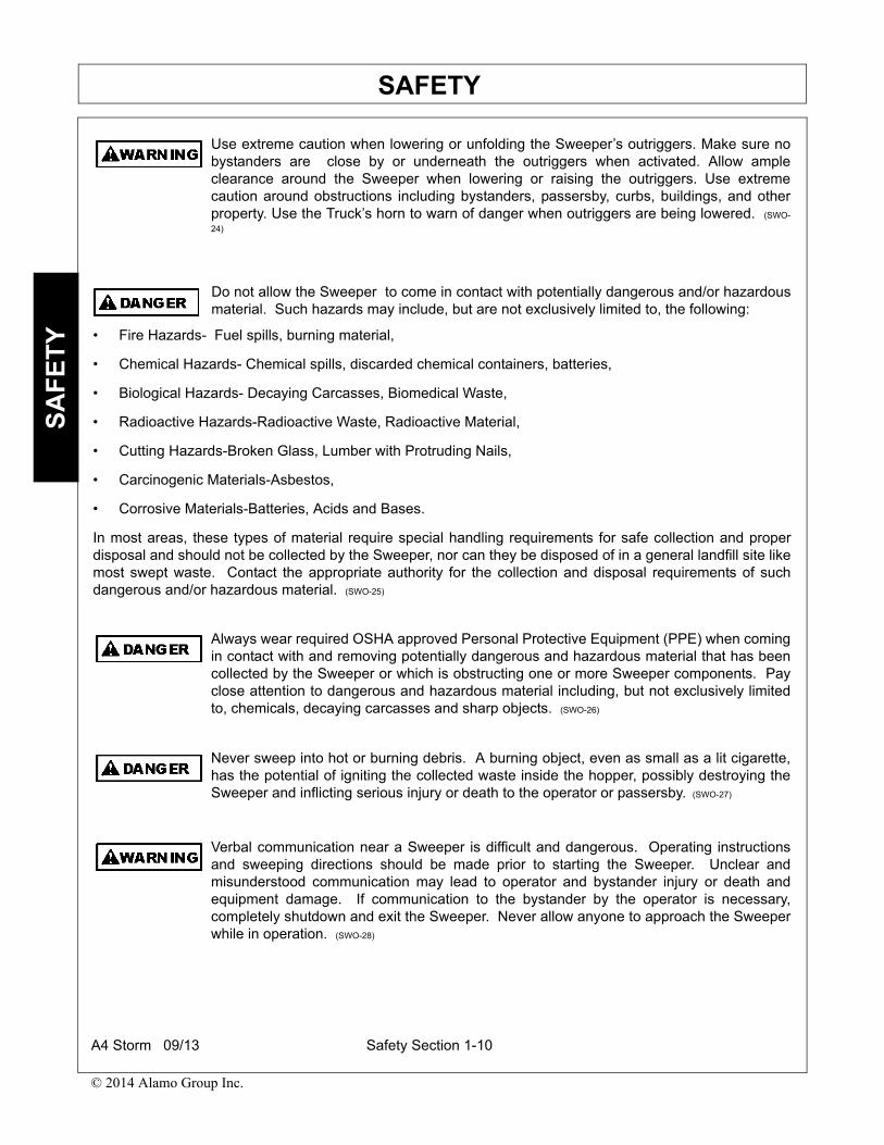
Use extreme caution when lowering or unfolding the Sweeper’s outriggers. Make sure nobystanders are close by or underneath the outriggers when activated. Allow ampleclearance around the Sweeper when lowering or raising the outriggers. Use extremecaution around obstructions including bystanders, passersby, curbs, buildings, and otherproperty. Use the Truck’s horn to warn of danger when outriggers are being lowered. (SWO-
24)
Do not allow the Sweeper to come in contact with potentially dangerous and/or hazardousmaterial. Such hazards may include, but are not exclusively limited to, the following:
• Fire Hazards- Fuel spills, burning material,
• Chemical Hazards- Chemical spills, discarded chemical containers, batteries,
• Biological Hazards- Decaying Carcasses, Biomedical Waste,
• Radioactive Hazards-Radioactive Waste, Radioactive Material,
• Cutting Hazards-Broken Glass, Lumber with Protruding Nails,
• Carcinogenic Materials-Asbestos,
• Corrosive Materials-Batteries, Acids and Bases.
In most areas, these types of material require special handling requirements for safe collection and properdisposal and should not be collected by the Sweeper, nor can they be disposed of in a general landfill site likemost swept waste. Contact the appropriate authority for the collection and disposal requirements of suchdangerous and/or hazardous material. (SWO-25)
Always wear required OSHA approved Personal Protective Equipment (PPE) when comingin contact with and removing potentially dangerous and hazardous material that has beencollected by the Sweeper or which is obstructing one or more Sweeper components. Payclose attention to dangerous and hazardous material including, but not exclusively limitedto, chemicals, decaying carcasses and sharp objects. (SWO-26)
Never sweep into hot or burning debris. A burning object, even as small as a lit cigarette,has the potential of igniting the collected waste inside the hopper, possibly destroying theSweeper and inflicting serious injury or death to the operator or passersby. (SWO-27)
Verbal communication near a Sweeper is difficult and dangerous. Operating instructionsand sweeping directions should be made prior to starting the Sweeper. Unclear andmisunderstood communication may lead to operator and bystander injury or death andequipment damage. If communication to the bystander by the operator is necessary,completely shutdown and exit the Sweeper. Never allow anyone to approach the Sweeperwhile in operation. (SWO-28)
A4 Storm 09/13 Safety Section 1-10
© 2014 Alamo Group Inc.

SAFETYS
AF
ET
Y
Never allow children to play on, under, or around the Sweeper nor allow children to operateSweeper controls. Children can slip or fall off the Sweeper and be injured or killed.Children can cause the Sweeper components to shift or fall crushing themselves or others.(SWO-29)
Allow Sweeper passengers only in situations where their presence is involved in thesweeping operation (operator training, supervision, maintenance inspection). Never carrypassengers whose presence distracts from the safe operation or transport of the Sweeper.Passengers must be seated securely and belted in the cab’s passenger seat. Never allowany person to ride on any other location of the Sweeper during operation or transport.(SWO-30)
Extreme caution should be used by the Sweeper operator when operating near passersby.Stop sweeping if anyone comes within 25 feet of the Sweeper to prevent possible passerbyinjury or death from being struck from a thrown object, entanglement with the brooms, orrun over. (SWO-31)
Under certain conditions, the Sweeper’s brooms are capable of propelling objects up to 25feet. Be extremely careful when sweeping large dense objects, such as gravel or brokenglass, that might become propelled and cause bodily injury to passersby or damage toproperty such as windows and vehicles. (SWO-32)
Make sure that no bystander, animal or obstruction such as a vehicle,building, or street sign are behind the Sweeper when backing up. The designof the Sweeper impairs operator rear vision when backing. Use extremecaution to ensure that the Sweeper is not backed into the path of pedestrianor vehicle traffic. Serious injury or death and property damage could resultfrom running into, being crushed by, or run over by a Sweeper. (SWO-33)
Make sure no bystanders or animals are within 25 feet of the Sweeper whendumping contents from or cleaning the hopper. Hopper contents, which mayexceed several thousand pounds, could fall and crush a bystander or ananimal resulting in possible injury or death. (SWO-34)
Do not operate the sweeper or start the auxiliary engine if the fan exhaust hose is removed,damaged or improperly installed on the outlet tube or sweeper head. The fan can throwobjects resulting in bodily injury to the operator or bystanders. (SWO-35)
Do not operate the sweeper or start the auxiliary engine with the sweeper broom coveropen or missing. The broom can throw objects or entanglement in the rotating broom canresult in bodily injures. (SWO-36)
Stay clear of hopper when it is being dumped. Make sure that no coworkers or bystandersare near the hopper when it is being raised or lowered. Serious injury could result fromentanglement with the hopper dump mechanism. (SWO-39)
A4 Storm 09/13 Safety Section 1-11
© 2014 Alamo Group Inc.

SAFETYS
AF
ET
Y
MAINTENANCE AND SERVICE SAFETY INSTRUCTIONS AND PRACTICES
If the sweeper is powered by CNG or other petroleum gas products, the sweeper must bestored outside or in a properly ventilated building to prevent the build up of escaping gas.Accumulated gas can be ignited by a spark causing an explosion. (SWO-40)
Avoid body contact with collected debris in the hopper. Use protective clothing includinggloves and eye protection when servicing or working in or around hopper. Collecteddebris in the hopper can cut or puncture resulting in serious bodily injuries and thetransmittal of diseases. (SWO-42)
Use extreme caution when operating the Sweeper in traffic. To alert motorist of theSweeper’s presence, the Sweeper is equipped with warning signals, flashing lights, and abuilt-in arrow board. Optional electrical lights, flashers and a warning bar light, strobe, orbeacon may be positioned on top of the cab. Use all equipped warning signals to alertmotorist and pedestrians of the Sweeper’s presence and relatively slow speed. Seriousinjury or death and property damage may occur if a vehicle collides with the Sweeper. (SWS-3)
Before starting a sweeping operation, make sure all the warning signal lights areconnected, visible and working. Routinely inspect the Sweeper’s headlights, brake lights,backup lights, and turn signal lights for operational condition. Immediately repair non-functioning lighting. Always follow all local traffic regulations while operating the Sweeper.(SWS-4)
Always turn on all safety lights and flashers when you operate the Sweeper. It isrecommended that you preset the beacon/strobe light switches to ON, so lights go onwhenever the auxiliary engine is ON and lights go OFF whenever the auxiliary engine isturned OFF. This presetting action has the additional benefit of alerting the operator if theauxiliary engine is inadvertently left ON. (SWS-5)
Periodically inspect all moving parts for wear and replace whennecessary with authorized service parts. Look for loose fasteners, wornor broken parts, and leaky or loose fittings. Make sure all pins havecotter pins and washers. Serious injury may occur from not maintainingthis Sweeper in good working order. (SWM-1)
A4 Storm 09/13 Safety Section 1-12
© 2014 Alamo Group Inc.

SAFETYS
AF
ET
Y
Inspect the entire Sweeper before each use. Accidents may occur or damage to theSweeper may result if the Sweeper is not maintained in good mechanical working order.
• Check for loose bolts, worn or broken parts, pinched hydraulic hoses, and leaky or loose fittings.
• Make sure all pins are secure and safety pins equipped.
• Make sure replacement parts (gutter broom heads) are the correct size and properly installed.
• Make sure all fluid levels are full and replenish as necessary.
• Make sure fuel, oil, and coolant caps are replaced and tightened.
• Make sure that the water tank cap is replaced.
• Check tire condition for tread wear and tire pressure at the rated PSI.
• Make sure that all safety shields and guards are attached and in good condition.
• Make sure all scheduled maintenance is up to date. (SWM-2)
Do not modify or alter this Sweeper. Do not permit anyone to modify or alter this Sweeper,any of its components or any Sweeper function. (SWM-3)
Use extreme care when climbing onto the Sweeper to perform repairs, maintenance, andcleaning. Use proper stands and ladders to access areas that cannot be reached fromground level. Slipping and falling off the Sweeper can cause serious injury or death. (SWM-4)
Never attempt to repair, lubricate, adjust, clean, remove obstructions or perform any othertype of service to any Sweeper component while the Sweeper is in motion or while theTruck and Auxiliary engine is running. Completely shut down the sweeping componentsand the Truck engine and wait for all motion to come to a complete stop and remove keysbefore servicing the Sweeper. Remove keys from both engines before working on thesweeper. (SWM-5)
Never leave the Sweeper unattended while the hopper bin is in the raised position.Accidental operation of the lifting lever or a hydraulic failure may cause a sudden drop ofthe unit which could result in injury or death by crushing. If the hopper must be raised for apurpose other than the time required to normally dump, or if someone is going to get underthe hopper for any reason, always secure the hopper safety prop into position. (SWM-6)
Never crawl under the hopper bin while the hopper is in the raised position unless properlysecured with the safety prop in position. Accidental operation of a lifting lever or hydraulicfailure may cause a sudden drop of the unit with injury or death by crushing. (SWM-7)
A4 Storm 09/13 Safety Section 1-13
© 2014 Alamo Group Inc.

SAFETYS
AF
ET
Y
Use proper protective equipment (gloves, safety eyewear, face shield, arm protection,possible respirator or particle mask) when handling gutter and sweeper brooms duringreplacement, adjustment, and maintenance. Broom bristles, which are sharp and coarse,could inflict puncture and stab wounds to the hands, arms, and/or eyes if proper protectiveequipment is not worn. (SWM-8)
Never crawl under any raised Sweeper component (gutter broom, sweeper head,suctionhead, hopper bin) unless the component is securely supported or blocked up and hydraulicpressure relieved. Accidental operation of the lifting lever or hydraulic failure may cause asudden drop of the unit with possible injury or death by crushing. (SWM-9)
Never remove the Sweeper exhaust head hose to perform repairs or maintenance while theSweeper is operating. Objects propelled from an open hose at a high velocity could causeserious injury or death. Always shut down the Truck and Auxiliary engine completely andwait for all motion to come to a complete stop before working on any Sweeper component.(SWM-10)
Escaping pressurized hydraulic oil generated by hydraulic pumps has the potential to inflictserious injury and possible death. Never attempt to repair a pump or hose or tighten aconnection while the system is pressurized. Always shut down the Truck and Auxiliaryengine and relieve hydraulic oil pressure before performing any repairs to the hydraulicsystem. (SWM-11)
Hydraulic pressure must be relieved from the Sweeper’s hydraulic circuit prior to doing anymaintenance or repair work and when the Sweeper is parked at the end of the day. Placethe Sweeper’s gutter brooms, sweeper broom, suction head, and outriggers on the groundor securely blocked up with the safety pins installed. Make sure the hopper bin is loweredonto the chassis or secured in the raised position with the safety prop in position. Turn offthe Truck and Auxiliary engine then engage the hydraulic remote cylinders several times torelieve hydraulic pressure prior to performing any maintenance or repair work. (SWM-12)
Water pressure generated by the high pressure water pump has the potential to inflictserious injury and death. Never attempt to repair a pump or hose or tighten a connectionwhile the system is pressurized. Always shut down the Truck and Auxiliary engine andrelieve water pressure by activating the system before performing any repairs to the highpressure water system. (SWM-13)
NEVER work on or near any engine component that has generated heat until it has cooleddown. Use extra caution around the exhaust manifold near the water valve and the turbocharger manifold tubes. NEVER check or replenish the fluid levels of the Truck andAuxiliary engine coolant or hydraulic circuit oil levels until sufficient time has passed (up to2 hours) to allow the system to cool down. Contact with a hot engine component oroperating fluid may result in serious injury from burns, scalding and possible death. (SWM-14)
A4 Storm 09/13 Safety Section 1-14
© 2014 Alamo Group Inc.

SAFETYS
AF
ET
Y
Never remove debris from or unclog jams in the suction hoses, gutter brooms, pickupbrooms, and all other areas of the Sweeper until both the Truck and Auxiliary Engine havebeen completely shutdown, all sweeping components have come to a complete stop andare lowered to ground level and hydraulic pressure relieved. Always wear PPE whenremoving collected material from the Sweeper. Serious injury or death may occur if any ofthese precautions are not followed when removing plugged or jammed sweepingcomponents. (SWM-15)
Use extreme caution when working in confined areas of the hopper bin or water tank for anextended period of time. Confined work areas may pose a danger because of the physicalconstraints imposed on the body. Routinely exit the confine to stretch and correct postureto prevent physical stress imposed on the body before bodily injury occurs. (SWM-16)
Use extreme caution when entering confined areas of the hopper bin to perform repairs,maintenance, and cleaning. Depending on any hazardous contents and/or fumescontained within the hopper bin, specialized Personal Protective Equipment such as aspecialized respirator, artificial oxygen source, and protective body suit may be required.Always use the buddy system when hazardous or oxygen depleting material is containedwithin the hopper. Never enter an enclosed area without Personal Protective Equipment ifcontents are unknown, possible injury and death may result if required precautions are nottaken. (SWM-17)
Use extreme caution when refueling the Sweeper, fuel is highly flammable and explosive ifnot handled safely. Always follow these precautions to reduce the dangers involved inrefueling:
• Completely shut down the Truck and Auxiliary Engines before refueling.
• Do Not refuel while smoking or near an open flame.
• Do Not store Sweeper with fuel in the tank in a building where fumes can reach an ignition source.
• To prevent a fire and explosion caused by static electric discharge while filling the tank, use a plastic fun-
nel. Avoid using a funnel that has a metal screen or filter.
• Avoid spilling fuel. Fuel is corrosive and can damage plastic and painted surfaces. Clean up spilled fuel
immediately.
• Store fuel and all oils at a site protected from moisture, dirt, and other contaminants. (SWM-18)
Never run the Truck or Auxiliary engine in a closed building or without adequate ventilation.The exhaust fumes can be hazardous and deadly to your health. If it is necessary to runthe Truck engine in an enclosed area, remove the exhaust fumes from the area to theoutdoors with an exhaust pipe extension. If you do not have an exhaust pipe extension, orif it is not possible to use one (Sweeping within a building), open doors and circulateoutside air into the area. (SWM-19)
A4 Storm 09/13 Safety Section 1-15
© 2014 Alamo Group Inc.

SAFETYS
AF
ET
Y
Engine Exhaust, some of its constituents, and certain vehicle components contain or emitchemicals known to the state of California to cause cancer and birth defects or otherreproductive harm. (SWM-20)
Do not operate this Sweeper with hydraulic oil or fuel leaking. Oil andfuel are dangerous and their presence could present a hazard. Do notcheck for leaks with your hand! Use a piece of heavy paper orcardboard. High-pressure oil streams from breaks in the line couldpenetrate the skin and cause tissue damage including gangrene. If oildoes penetrate the skin, have the injury treated immediately by aphysician knowledgeable and skilled in this procedure. (SWM-21)
Always read carefully and comply fully with the manufacturer’sinstructions when handling fuels, oils, solvents, cleansers, and anyother chemical agent. (SWM-22)
Battery posts, terminals and related accessories contain lead and lead compounds,chemicals known to the state of California to cause cancer and birth defects or otherreproductive harm. Wash Hands after handling. (SWM-23)
Avoid contact with hot surfaces on the bottom of the skid shoes. Use gloves and eyeprotection when servicing hot components. Contact with a hot surface can cause seriousinjury from burns or scalding. (SWM-24)
Remove the negative battery cable from the battery before performing any maintenance onthe electrical system to prevent an accidental circuit shorting and sparks. Sparks can resultin wiring damage, fire or personal injury. (SWM-25)
Use caution when working around the hopper doors. Do not let the doors fall uncontrolledonto bystanders or coworkers. Use the door locks to hold the doors open while cleaning orperforming maintenance in or around the hopper. (SWM-26)
Before conducting maintenance on the sweeper stop the truck, place the transmission inpark and set the parking brake. Turn the Truck engine and the auxiliary engine off andremove the keys to prevent inadvertent or accidental starting of the engines. Unexpectedengine start up or truck movement can result in serious bodily injuries or death. (SWM-27)
Do not inspect or approach the sweeper fans while they are rotating. Serious bodily injuryincluding dismemberment can result. Shut down the Truck engine and wait for all rotatingmotion to stop completely before attempting to inspect or perform maintenance on or nearthe fans. (SWM-28)
A4 Storm 09/13 Safety Section 1-16
© 2014 Alamo Group Inc.

SAFETYS
AF
ET
Y
PARTS INFORMATION
PARTS INFORMATIONSchwarze Sweepers use balanced and matched system components for broom carriers, brooms, suctionheads, and other components. These parts are made and tested to Schwarze specifications. Non-genuine or“will fit" parts do not consistently meet these specifications. The use of non-genuine or “will fit” parts mayreduce Sweeper performance, void Sweeper warranties, and present a safety hazard. Use genuine SchwarzeSweeper parts for economy and safety. (SWG-06)
SEE YOUR LOCAL SCHWARZE DEALER
A4 Storm 09/13 Safety Section 1-17
© 2014 Alamo Group Inc.

SAFETYS
AF
ET
Y
Decal LocationNOTE: Schwarze supplies safety decals on this product to promote safe operation. Damage to the decals mayoccur while in shipping, use, or reconditioning. Schwarze cares about the safety of its customers, operators,and bystanders, and will replace the safety decals on this product in the field, free of charge (Some shippingand handling charges may apply). Contact your Schwarze dealer to order replacement decals.
A4 Storm 09/13 Safety Section 1-18
© 2014 Alamo Group Inc.

SAFETYS
AF
ET
Y
ITEM PART NO. QTY TYPE DESCRIPTION
1. 20340 2 REFLECTOR Amber Reflector
2. 23258 4 CAUTION Keep Off, No Step
3. 22560 1 WARNING Do Not Remove Hose With Engine Running
4. 22527 2 CAUTION Spinning Broom
5. 29635 2 CAUTION Open Only When Cool
6. 22536 6 WARNING Hand Warning Symbol
7. 29634 1 DANGER No Smoking
8. 22528 1 CAUTION No Step
9. 29410 1 INSTRUCT Fan Inlet
10. 22531 2 INSTRUCT Drain Water
11. 22563 2 WARNING Do Not Work with Hopper in Dump Position
12. 22891 2 WARNING Fan Hazard
13. 29154 1 WARNING Suction Tube
14. 22533 1 INSTRUCT Use Only Tellus 68
15. 29628 2 WARNING Do Not Use Hands to Check Oil Leak
16. 28879 2 WARNING Do Not Operate without Guards
17. 22529 1 CAUTION Before Unloading Instructions
18. 22530 1 WARNING Sweeping Speed
19. 23182 1 WARNING Read Manual
20. 29298 1 INSTRUCT Starting Procedures
21. 29636 1 PELIGRO Get Manual Translated
22. 29637 1 WARNING Remove Keys before Maintenance
23. 29639 1 INSTRUCT Use Genuine Schwarze Parts
24. 60668 1 INSTRUCT Use Low Sulfur Diesel
A4 Storm 09/13 Safety Section 1-19
© 2014 Alamo Group Inc.

SAFETYS
AF
ET
Y
Decal Description
A4 Storm 09/13 Safety Section 1-20
© 2014 Alamo Group Inc.

SAFETYS
AF
ET
Y
A4 Storm 09/13 Safety Section 1-21
© 2014 Alamo Group Inc.

SAFETYS
AF
ET
Y
A4 Storm 09/13 Safety Section 1-22
© 2014 Alamo Group Inc.

SAFETYS
AF
ET
Y
A4 Storm 09/13 Safety Section 1-23
© 2014 Alamo Group Inc.

SAFETYS
AF
ET
Y
A4 Storm 09/13 Safety Section 1-24
© 2014 Alamo Group Inc.

SAFETYS
AF
ET
Y
A4 Storm 09/13 Safety Section 1-25
© 2014 Alamo Group Inc.

SAFETYS
AF
ET
Y
Federal Laws and Regulations
This section is intended to explain in broad terms the concept and effect of federal laws and regulations concerningemployer and employee equipment operators. This section is not intended as a legal interpretation of the law andshould not be considered as such.Employer-Employee Operator RegulationsU.S. Public Law 91-596 (The Williams-Steiger Occupational and Health Act of 1970) OSHA
This Act Seeks:“...to assure so far as possible every working man and woman in the nation safe and healthful workingconditions and to preserve our human resources...”
DUTIESSec. 5 (a) Each employer-(1) shall furnish to each of his employees employment and a place of employment which are free fromrecognized hazards that are causing or are likely to cause death or serious physical harm to his employees;(2) shall comply with occupational safety and health standards promulgated under this Act.(b) Each employee shall comply with occupational safety and health standards and all rules, regulations andorders issued pursuant to this Act which are applicable to his own actions and conduct.
OSHA RegulationsOSHA regulations state in part: “At the time of initial assignment and at least annually thereafter, the employershall instruct every employee in the safe operation and servicing of all equipment with which the employee is,or will be involved.
Employer Responsibilities:To ensure employee safety during Truck and Patcher operation, it is the employer’s responsibility to:1. Train the employee in the proper and safe operation of the Truck and Patcher.2. Require that the employee read and fully understand the Truck and Patcher Operator’s manual.3. Permit only qualified and properly trained employees to operate the Truck and Patcher.4. Maintain the Truck and Patcher in a safe operational condition and maintain all shields and guards on the
equipment.5. Ensure the Truck is equipped with a functional seat belt and require that the employee operator securely fasten
the safety belt at all times.6. Provide the required tools to maintain the Truck and Patcher in a good safe working condition and provide the
necessary support devices to secure the equipment safely while performing repairs and service.OSHA 1910.147(c)(1) Energy Control Program
The employer shall establish a program consisting of energy control procedures, employee training andperiodic inspections to ensure that before any employee performs any servicing or maintenance on a machineor equipment where the unexpected energizing, startup or release of stored energy could occur and causeinjury, the machine or equipment shall be isolated from the energy source and rendered inoperative.
OSHA 1926.417 Lockout and Tagging(a) Controls. Controls that are to be deactivated during the course of work on energized or de-energizedequipment or circuits shall be tagged.(b) Equipment and Circuits. Equipment or circuits that are de-energized shall be rendered inoperative andshall have tags attached at all points where such equipment or circuits can be energized.
OSHA 1926.600(a)(3)(ii)Whenever the equipment is parked, the parking brake shall be set. Equipment parked on inclines shall havethe wheels chocked and the parking brake set.
Employee’s Responsibilities:Remove the truck keys and keep them in your pocket before performing any service, maintenance, cleaning or beforeany person enters into equipment hopper. The Truck engine controls must be shut off and prevented from accidentalactivation.1. Follow all safety rules and regulations.2. Use all safety equipment as prescribed in Operator’s Manual.3. Report any unsafe conditions.4. Be aware of and protect the safety of coworkers or others in vicinity.
A4 Storm 09/13 Safety Section 1-26
© 2014 Alamo Group Inc.

Introduction Section 2-1
© 2014 Alamo Group Inc.
INTRODUCTION SECTION

INTRODUCTIONIN
TR
OD
UC
TIO
N
We are pleased to have you as an Schwarze customer. Your Sweeper has been carefully designed with careand built with quality materials by skilled workers to give maximum service with minimum down time. Thismanual is provided to give you the necessary operating and maintenance instructions for keeping yoursweeper in top operating condition. Careful use and timely service saves extensive repairs and costlydowntime losses. Please read this manual thoroughly. Understand what each control is for and how to use it.
Safety is of primary importance to the owner/operator and to the manufacturer. Observe all safety precautionsdecaled on the machine and noted throughout the manual for safe operation of implement. If any assistance oradditional information is needed, contact your authorized Schwarze dealer. The owner/operator/dealer shouldknow and understand the Safety Messages before assembly and be aware of the hazards of operating thiscutter during assembly, use, and maintenance. The Safety Alert Symbol combined with a Signal Word, as seenbelow, is intended to warn the owner/operator of impending hazards and the degree of possible injury facedwhen operating this machine.
Indicates an imminently hazardous situation that, if not avoided, WILL result in DEATH ORVERY SERIOUS INJURY.
Indicates an imminently hazardous situation that, if not avoided, COULD result in DEATHOR SERIOUS INJURY.
Indicates an imminently hazardous situation that, if not avoided, MAY result in MINORINJURY.
Identifies special instructions or procedures that, if not strictly observed, could result indamage to, or destruction of the machine, attachments or the environment.
Your new Schwarze A4 Storm Sweeper incorporates the very latest in sweeper manufacturing technology. Thissweeper was designed to clean surfaces with a high rate of efficiency and minimize operational cost. A singlefan is used to create both the air pressure and the suction which power the sweeping function. This volume ofair, which is pumped at high velocity into the sweeper pickup head, provides its superior sweepingperformance. This sweeper use a ‘Closed Loop’ or ‘Regenerative Air’ system to accomplish debris pickup. Partof the fan’s forced air may be vented out of the fan housing, which provides increased performance overcompetitive models. You will find this design is much more dependable and requires less maintenance thanthat of broom models.
To obtain the best use of the sweeper’s equipment, we strongly recommend that the operator be required tothoroughly read, understand and follow all of the applicable information in this Manual prior to and during theoperation of this sweeper. Daily cleaning and strict adherence to other unit’s routine maintenance schedulesare major factors in keeping your unit in like-new condition. Ensuring that service personnel and operatorsbecome familiar with the information unique to this make and model of sweeper will greatly contribute to cost-effective operation and many years of quality service.
Our goal at Schwarze Industries is always, 100% customer satisfaction. We’re confident you’ll find this newsweeper to be the best built on the market, and it’s backed by a company with a service commitment that’ssecond to none. If you need help, don’t hesitate to call. Many ideas for improvements to previous models havecome from users in the field. If you have an idea or suggestion on how we might make our product even better,please let us know by calling toll free, 1-800-879-7933.
A4 Storm 09/13 Introduction Section 2-2
© 2014 Alamo Group Inc.
INTRODUCTIONIN
TR
OD
UC
TIO
N
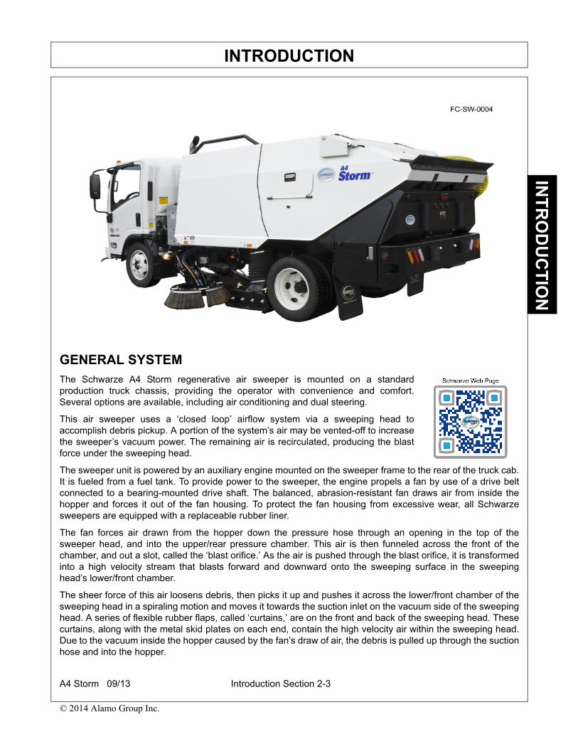
GENERAL SYSTEMThe Schwarze A4 Storm regenerative air sweeper is mounted on a standardproduction truck chassis, providing the operator with convenience and comfort.Several options are available, including air conditioning and dual steering.
This air sweeper uses a ‘closed loop’ airflow system via a sweeping head toaccomplish debris pickup. A portion of the system’s air may be vented-off to increasethe sweeper’s vacuum power. The remaining air is recirculated, producing the blastforce under the sweeping head.
The sweeper unit is powered by an auxiliary engine mounted on the sweeper frame to the rear of the truck cab.It is fueled from a fuel tank. To provide power to the sweeper, the engine propels a fan by use of a drive beltconnected to a bearing-mounted drive shaft. The balanced, abrasion-resistant fan draws air from inside thehopper and forces it out of the fan housing. To protect the fan housing from excessive wear, all Schwarzesweepers are equipped with a replaceable rubber liner.
The fan forces air drawn from the hopper down the pressure hose through an opening in the top of thesweeper head, and into the upper/rear pressure chamber. This air is then funneled across the front of thechamber, and out a slot, called the ‘blast orifice.’ As the air is pushed through the blast orifice, it is transformedinto a high velocity stream that blasts forward and downward onto the sweeping surface in the sweepinghead’s lower/front chamber.
The sheer force of this air loosens debris, then picks it up and pushes it across the lower/front chamber of thesweeping head in a spiraling motion and moves it towards the suction inlet on the vacuum side of the sweepinghead. A series of flexible rubber flaps, called ‘curtains,’ are on the front and back of the sweeping head. Thesecurtains, along with the metal skid plates on each end, contain the high velocity air within the sweeping head.Due to the vacuum inside the hopper caused by the fan’s draw of air, the debris is pulled up through the suctionhose and into the hopper.
A4 Storm 09/13 Introduction Section 2-3
© 2014 Alamo Group Inc.

INTRODUCTIONIN
TR
OD
UC
TIO
N
Once inside the hopper, a number of strategically placed water nozzles may be used to decrease the amountof airborne dust. As the dust comes in contact with the water spray, it becomes heavier. The dust and debris-laden air slows down when entering the large volume of the hopper, so heavier objects fall to the hopperbottom. The air is then drawn through a screen in the top of the hopper which removes any remaining lighterobjects. Only fine particles of dust remain to be pulled through the screen and into the dust separator in thefront of the hopper. As air is pulled from the dust separator by the fan, it develops a spiraling action andcentrifugal force throws the remaining fine dust against the walls of the separator, returning it through slots tothe hopper bottom. The fan then draws the cleaned air from the dust separator back into the fan housing andthe cycle begins again.
For your convenience and safety, the Schwarze A4 Storm sweeper is controlled via a console located in thetruck cab. The console allows for remote operation of the hydraulic, dust suppression, and lighting systems, aswell as the sweeper’s auxiliary engine.
Your new Schwarze A4 Storm sweeper may also be factory equipped with a number of options. In addition,some options may be added to the sweeper after leaving the factory. For more details about the manyavailable options, contact a Schwarze Industries sales representative at 1-800-879-7933.
EQUIPMENT SPECIFICATIONS
Auxiliary Engine Specifications, Perkins 804D-TThe Standard Auxiliary Engine is a Model 804D-33T, 74 HP, 4 cylinder
Make ..................................................................... Perkins DieselModel ........................................................................... 840D-33THorsepower..................................................74 HP @ 2600 RPMDisplacement-L (cu. in.) .................................................3.3 (201)Type .................................................................... In-Line, 4-CycleNumber of Cylinders .................................................................. 4Bore and Stroke-in. (mm)......................... 3.70 x 4.72 (94 x 120)Aspiration .................................................. Turbo-Charged DieselTorque ......................................................195 ft-lb. @ 1600 RPMCompression Ratio ............................................................ 19.0:1
Aux. Drive........... Engine Mounted, Hydraulic Pump Gear DrivenCooling ............................................................................... LiquidAlternator........................................................................... 12 VoltSafety Shutdown ............Oil Pressure, Water Temp, Water LevelAir Filter ..................................................2-Stage with PrecleanerOil Filter ............................................................Full Flow Spin-OnLength-in. (mm) ............................................................30.9 (784)Width-in. (mm)..............................................................25.5 (649)Height-in. (mm).............................................................30.3 (769)Weight (dry)-lb. (kg)..................................................584 (265 kg)
A4 Storm 09/13 Introduction Section 2-4
© 2014 Alamo Group Inc.

INTRODUCTIONIN
TR
OD
UC
TIO
N
Sweeper Specifications
Sweeping Path:Sweeping Head Only ............................................80” (2032 mm)Sweeping Head and One Gutter Broom .............100” (2540 mm)Sweeping Head and Two Gutter Brooms............120” (3048 mm)
Sweeper Body:Construction...........................Welded 10-Gauge Steel Plate with
with a 3/16 Steel Hopper FloorSafety Prop ..................................................................Dual Steel
Chassis:Mount on various chassis to meet requirements
Hopper:Volumetric Capacity .....................................4.3 cu. yds. (3.3 m3)Construction..................................................................10 GaugeType of Dumping........................................................... HydraulicInspection Doors ...................... One on Each Side of the HopperType and Location of Controls ..............................Electric/In CabDumping Height ....................................................67” (1701 mm)Dump Angle ............................................................................88°Interior Coating .................................................. Durable CoatingExterior Coating ............................... Sealer/Primer/Polyurethane
Blower System:Type ..............................................................Closed-Face RadialDrive........................ Direct via 3V 8-Groove, Banded Power BeltConstruction.............................................................Hardox SteelBalance ......................................................1.5 Grams on 2 SidesDiameter .................................................................30” (762 mm)Housing Liner........................................... Bolt-In Corded RubberMounting ...............................Two Regreasable Sealed BearingsVacuum Enhancer................................. For Heavy/Light Material
Sweeping Head:Type ............................Dual Chambered, Full Width Blast OrificeOperating Direction ....................................Forward and ReverseSuspension ...................................... Adjustable Spring BalancedLength ...................................................................80” (2032 mm)Pressure Hose Diameter.........................................12” (305 mm)Suction Hose Diameter ...........................................12” (305 mm)Hose Construction ..................................................3/8” (9.5 mm)
Wire-Reinforced Molded RubberHead Area...............................................2080 sq in (13419 cm2)Controls............................................. Hydraulic Raise and LowerSkids .......................................... Double Wide Tungsten CarbideConstruction......................................................................... Steel
Electrical System:Voltage .............................................................................. 12 VoltBattery............................................................2 at 750 CCA EachSweeper Engine Alternator .......................................80 AmperesCircuit Breakers ................................................. Resettable Type
Dust Control System:Type...................................................High Pressure/Low VolumeCapacity ...............................................130 Gallons (492.1 liters)Tank Construction.................................................... PolyethyleneFilter ...............................................200 Mesh Screen, CleanableFill Diameter ......................................................... 2.5” (63.5 mm)Fill Hose ........................................................ 25 Feet (7620 mm)Controls ................................................................Electric, In CabNozzles............................................................. 2 on Each Broom
4 Around Suction Head4 Inside Hopper
Gutter Brooms:Type..............................................................Vertical Steel DiggerLocation.................... Right and Left, Forward of Sweeping HeadDiameter................................................................. 39” (991 mm)Drive .............................................................................. HydraulicSuspension...............................................Torque-Sensing SpringWear Adjustment.......................................................... AutomaticPressure ........................................................................... ManualSpeed .................................................... Variable, Non-ReversingSegments ..............................................4 Each Side, DisposableTilt Angle Adjustment ........................... Hyd with In-Cab Controls
Hydraulic System:Type..................................................... Fixed Displacement GearDrive ...........................................................................Direct GearMaximum Pressure .......................................2500 PSI (173 bar.)Reservoir ...............................................................16 Ga (60.6 L)Filter ............................................................... 10-Micron Spin-OnProtection ...................................................Pressure Relief ValveControls .............................................................Electro-Hydraulic
80 Mesh
PaintOne coat of sealer/primer and 2 coats of DuPont Imron Elitepolyurethane in standard white color
A4 Storm 09/13 Introduction Section 2-5
© 2014 Alamo Group Inc.

INTRODUCTIONIN
TR
OD
UC
TIO
N
HYDRAULIC SYSTEM
Hydraulic fluid is pulled from the reservoir into themechanically driver hydraulic pump mounted on theauxiliary engine. The pump passes the pressurizedhydraulic fluid into the manifold, mounted above theleft-hand-side water reservoir. Directional valvesattached to the side of the manifold are operatedelectrically from the sweeper’s in-cab console.These directional valves are used to channel fluidflow to the various sweeper functions (hopperdumping, the raising and lowering of the sweeperhead, and gutter broom operation).
An optional 12-volt auxiliary pump may be added.Because the pump is powered by the truck engine’s12 volt battery, it can be used to dump the hopper orraise the sweeping head without running thesweeper engine.
HYDRAULIC MANIFOLD
AUXILIARY HYDRAULIC PUMP
A4 Storm 09/13 Introduction Section 2-6
© 2014 Alamo Group Inc.
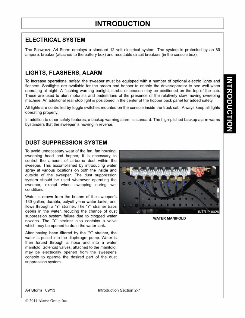
INTRODUCTIONIN
TR
OD
UC
TIO
N
ELECTRICAL SYSTEM
The Schwarze A4 Storm employs a standard 12 volt electrical system. The system is protected by an 80ampere. breaker (attached to the battery box) and resettable circuit breakers (in the console box).
LIGHTS, FLASHERS, ALARMTo increase operational safety, the sweeper must be equipped with a number of optional electric lights andflashers. Spotlights are available for the broom and hopper to enable the driver/operator to see well whenoperating at night. A flashing warning barlight, strobe or beacon may be positioned on the top of the cab.These are used to alert motorists and pedestrians of the presence of the relatively slow moving sweepingmachine. An additional rear stop light is positioned in the center of the hopper back panel for added safety.
All lights are controlled by toggle switches mounted on the console inside the truck cab. Always keep all lightsoperating properly.
In addition to other safety features, a backup warning alarm is standard. The high-pitched backup alarm warnsbystanders that the sweeper is moving in reverse.
DUST SUPPRESSION SYSTEMTo avoid unnecessary wear of the fan, fan housing,sweeping head and hopper, it is necessary tocontrol the amount of airborne dust within thesweeper. This accomplished by introducing waterspray at various locations on both the inside andoutside of the sweeper. The dust suppressionsystem should be used whenever operating thesweeper, except when sweeping during wetconditions.
Water is drawn from the bottom of the sweeper’s130 gallon, durable, polyethylene water tanks, andflows through a “Y” strainer. The “Y” strainer trapsdebris in the water, reducing the chance of dustsuppression system failure due to clogged waternozzles. The “Y” strainer also contains a valvewhich may be opened to drain the water tank.
After having been filtered by the “Y” strainer, thewater is pulled into the diaphragm pump. Water isthen forced through a hose and into a watermanifold. Solenoid valves, attached to the manifold,may be electrically opened from the sweeper’sconsole to operate the desired part of the dustsuppression system.
WATER MANIFOLD
A4 Storm 09/13 Introduction Section 2-7
© 2014 Alamo Group Inc.
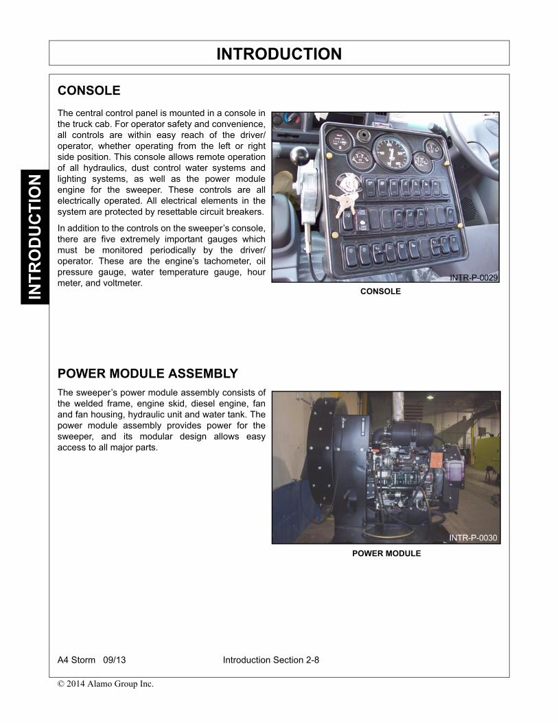
INTRODUCTIONIN
TR
OD
UC
TIO
N
CONSOLE
The central control panel is mounted in a console inthe truck cab. For operator safety and convenience,all controls are within easy reach of the driver/operator, whether operating from the left or rightside position. This console allows remote operationof all hydraulics, dust control water systems andlighting systems, as well as the power moduleengine for the sweeper. These controls are allelectrically operated. All electrical elements in thesystem are protected by resettable circuit breakers.
In addition to the controls on the sweeper’s console,there are five extremely important gauges whichmust be monitored periodically by the driver/operator. These are the engine’s tachometer, oilpressure gauge, water temperature gauge, hourmeter, and voltmeter.
POWER MODULE ASSEMBLYThe sweeper’s power module assembly consists ofthe welded frame, engine skid, diesel engine, fanand fan housing, hydraulic unit and water tank. Thepower module assembly provides power for thesweeper, and its modular design allows easyaccess to all major parts.
CONSOLE
POWER MODULE
A4 Storm 09/13 Introduction Section 2-8
© 2014 Alamo Group Inc.

INTRODUCTIONIN
TR
OD
UC
TIO
N
AUXILIARY ENGINE
The sweeper engine, which is diesel-powered, is mounted on an adjustable frame tray called the engine skid,and is normally fueled by the truck’s main fuel tank. Power produced by the engine is transmitted to the fan bya drive belt. For safety and convenience, all controls and gauges for the sweeper engine are located inside thecab on the central console.
For detailed information on the sweeper’s engine, consult the engine’s Owner’s Manual which is attachedseparately.
FAN DRIVE BELTThe fan is connected to the rear of the power module engine by an eight-groove drive belt. This belt is loopedaround the drive pulley on the power module engine and the pulley on the fan shaft. For safety, it is protectedby a metal belt guard.
FANThe Schwarze-exclusive Whisper Wheel™ is acentrifugal, backward curving fan. This uniquedesign results in reduced fan noise and requiresless auxiliary engine horsepower to operate. Thefan produces the air pressure and vacuum requiredfor the sweeper to operate. It is a balanced,reinforced, abrasion-resistant fan on a bearing-mounted drive shaft. Construction is of heavy steel.The fan is propelled by the power module engine,and is located within the fan housing attached to therear of the power module.
Air enters the fan housing inlet with great force. Caution should be used when the powermodule is running and the hopper is up. To avoid being pulled into the fan, do not wear looseclothes or position yourself near the fan housing inlet.
WHISPER WHEEL ™ FAN
A4 Storm 09/13 Introduction Section 2-9
© 2014 Alamo Group Inc.

INTRODUCTIONIN
TR
OD
UC
TIO
N
FAN HOUSING
The fan housing is mounted to the rear of the powermodule. Because of the sand blast effect of theairborne material traveling through the dustseparation chamber and into the fan housing, theinside of the fan housing is protected by a bolt-onreplaceable rubber liner.
A sweeping condition air bleeder, located in back ofthe fan housing, just above the rubber exhausthose. The bleeder is a damper door operated by anelectric actuator. A switch on the control panelconsole mounted in the truck cab operates theactuator. During normal operating conditions, thebleeder door is closed and air from the fan is forcedinto the sweeper head.
In sweeping conditions where there areconcentrations of leaves or other light debris, theforce of the blast orifice air pushing against the rearside of the front curtain prevents light debris fromentering the head. By opening the bleeder door, airfrom the fan is diverted away from the sweepinghead’s pressure chamber and exhausted out of thesweeper. The air flow pressure is decreased in thepressure chamber and blast orifice, which relievespressure against the rear side of the main curtain.This allows light debris to push under the maincurtain and into the sweeper head.
SWEEPING HEADThe sweeping head is the actual ‘sweepingcomponent’ of the air sweeper. It is attached to theunderside of the frame by a set of drag arms,tension springs and hydraulic cylinders mounted onboth sides of the sweeping head. The hydrauliccylinders and tension springs control the verticalmovement of the head. A switch mounted on thecontrol console in the truck cab operates the liftcylinders.
CONSOLE
SWEEPING HEAD
A4 Storm 09/13 Introduction Section 2-10
© 2014 Alamo Group Inc.

INTRODUCTIONIN
TR
OD
UC
TIO
N
The sweeping head is connected to the fan housing and hopper inlet tube by two hoses: one on the pressureside and one on the vacuum side. On the pressure side, the hose is connected from the fan housing to thepressure inlet tube on the head. One end of the vacuum hose is connected to the suction inlet tube on the headand the other end to the transition ring which seals against the hopper inlet tube when the hopper is in thelowered position. Both hoses are held in place by metal band clamps located on the top and bottom of eachhose.
The sweeping head is designed so the air pressure from the fan will produce the maximum cleaningperformance. The fan forces air from the hopper down the pressure hose, and into the upper/rear pressurechamber of the sweeping head. This air is then funneled across the front of the chamber, and out a slot calledthe ‘blast orifice’. As the air is pushed through the blast orifice, it is transformed into a high velocity air streamthat is channeled forward and downward onto the sweeping surface in the sweeping head’s lower/frontchamber. The force of this air loosens debris and pushes it toward the suction inlet, which is located on theright side of the head. Skid plates at each end, plus a series of flexible rubber flaps in both front and rear,contain the powerful air stream beneath the sweeping head. As the debris-laden air nears the suction inlet, thevacuum in the hopper created by the fan pulls the debris out of the sweeping head and up through the suctionhose.
HOPPERThe sweeper’s hopper is designed to contain thedebris picked up by the sweeping head. It isconstructed of heavy gauge steel for years oftrouble-free service. The hopper is mounted to aheavy duty frame which is fastened to the truck’schassis. This provides a stable base to mount thehydraulic cylinders used to raise the hopper into thedump position. A door on each side of the hopper,often called an inspection door, provides easyaccess to clean the hopper after dumping. Thesedoors can also be used to directly place objects intothe hopper that are too large to be picked up by thesweeping head. A door has been installed on top ofthe hopper to provide easy access for cleaning thehopper’s intake screen. HOPPER RAISED
A4 Storm 09/13 Introduction Section 2-11
© 2014 Alamo Group Inc.

INTRODUCTIONIN
TR
OD
UC
TIO
N
AVAILABLE OPTIONS
The following sections detail option that may be installed on your particular sweeper.
• Gutter Brooms
• Gutter Broom Power Tilt
• Gutter Broom Extension Override (GEO)
• Dual Steering
• Camera System
• Hand Hose
• Magnet
• High Volume Wash down
• Additional Water Tank
• Front Spray Bar
• Hopper Deluge
• Hopper Drain
• Sound Suppression Package
• Load Weight Indicator
NOTE: Availability of options may change without notice. Please consult your Schwarze dealer for a list ofcurrently available options.
Gutter BroomThe Schwarze A4 Storm rotating hydraulic gutterbrooms have been designed to dig debris loosefrom the gutter or similar areas and direct it across,and in front of, the sweeping head where it can bepicked up. The optional gutter brooms are mountedunder the chassis to the rear of the truck cab onboth the left and/or right sides of the sweeper. Theyare suspended from the frame on a hydraulically-controlled arm which is operated from the controlconsole inside the truck cab. The hydraulic motorswhich turn the brooms’ bristles are mounted insidethe disc that spins on the end of each arm. Whennot in use, the gutter brooms are hydraulically heldand locked into position under the truck, up and offthe pavement. This unique design enables thesweeper to have the largest possible sweepingwidth, and at the same time, provides maximumground clearance and minimum width when thegutter brooms are in the travel position.
GUTTER BROOM
A4 Storm 09/13 Introduction Section 2-12
© 2014 Alamo Group Inc.

INTRODUCTIONIN
TR
OD
UC
TIO
N
Dual SteeringDual steering is an option which allows the operatorof the sweeper to drive from the left or right handside of the truck. Major components relative tovehicle operation - such as the steering wheel withself-canceling turn signals, the brake pedal and theaccelerator - are duplicated on both sides. Drivingfrom the right hand side gives an operator bettercontrol of the sweeper while sweeping areas on theright side of the truck.
Camera SystemThe optional camera system may be used to increase an operator’s field of vision. A camera is mounted belowthe right water reservoir just behind the gutter broom. The camera is mounted to point forward and down. Thisangle allows observation of the gutter broom’s operation as well as provides a view of approaching curb lineobstacles. A second camera, mounted at the rear of the hopper, views what is directly to the rear of thesweeper. When the sweeper is shifted into reverse, the picture on the dash-mounted monitor automaticallyswitches to the rear view. Both cameras provide a wide field of vision.
DUAL STEERING
REAR CAMERA CAMERA MONITOR
A4 Storm 09/13 Introduction Section 2-13
© 2014 Alamo Group Inc.
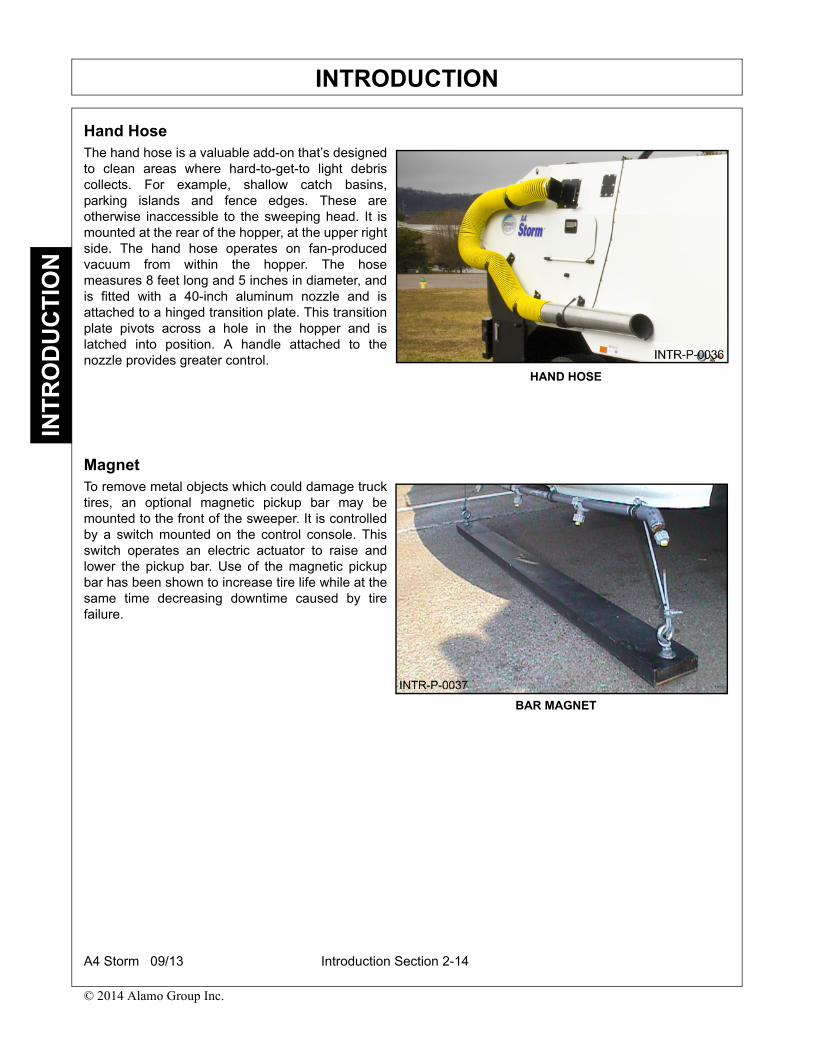
INTRODUCTIONIN
TR
OD
UC
TIO
N
Hand HoseThe hand hose is a valuable add-on that’s designedto clean areas where hard-to-get-to light debriscollects. For example, shallow catch basins,parking islands and fence edges. These areotherwise inaccessible to the sweeping head. It ismounted at the rear of the hopper, at the upper rightside. The hand hose operates on fan-producedvacuum from within the hopper. The hosemeasures 8 feet long and 5 inches in diameter, andis fitted with a 40-inch aluminum nozzle and isattached to a hinged transition plate. This transitionplate pivots across a hole in the hopper and islatched into position. A handle attached to thenozzle provides greater control.
MagnetTo remove metal objects which could damage trucktires, an optional magnetic pickup bar may bemounted to the front of the sweeper. It is controlledby a switch mounted on the control console. Thisswitch operates an electric actuator to raise andlower the pickup bar. Use of the magnetic pickupbar has been shown to increase tire life while at thesame time decreasing downtime caused by tirefailure.
HAND HOSE
BAR MAGNET
A4 Storm 09/13 Introduction Section 2-14
© 2014 Alamo Group Inc.

INTRODUCTIONIN
TR
OD
UC
TIO
N
Front Spray BarA front spray bar is available and may be added tothe sweeper’s dust suppression system to increasedramatically the amount of water that may beapplied to the sweeping surface. The spray bar,mounted to the front bumper, employs 7 spraynozzles whose overlapping patterns are used tothoroughly and evenly dampen the area in front ofthe sweeper to reduce airborne dust. The spray baris operated by a switch located on the in-cabconsole.
Hopper DelugeA tube protruding from the outer skin on the side of the hopper is connected to two large water nozzlespositioned inside the hopper. A 2-1/2” fire hose, supplied with the hopper deluge system, may be attached toboth the tube and a fire hydrant. When the hydrant is opened, the inside of the hopper is washed with amassive amount of pressurized water. This ‘deluge’ blasts free most dirt and stubborn grime adhering to theinside of the hopper and hopper screen, simplifying and shortening the sweeper’s cleanup.
Hopper DrainAlthough certain instances may require that liquid picked up by the sweeper be removed to a specified dumpsite. Often, it would be preferable to return any unwanted liquid, such as rain water, to the sweeping surface toreduce load weight/mass and permit longer sweeping between dumping intervals. An optional drain located atthe front of the hopper offers the capability of draining liquid from the hopper while the sweeper is operating.This allows the sweeper to be operated in a business-as-usual fashion even during wet weather.
Sound Suppression PackageA sound package, which uses sound deadening material applied to the inside of the hopper shroudsurrounding the auxiliary engine compartment, is used to lower the sweeper’s noise level rating. This option isof special consideration is cases where the sweeper is being used in residential areas.
FRONT SPRAY BAR
A4 Storm 09/13 Introduction Section 2-15
© 2014 Alamo Group Inc.

INTRODUCTIONIN
TR
OD
UC
TIO
N
Customer AssistanceSchwarze Industries is noted for its commitment to customer satisfaction. In addition to many AuthorizedDealers located throughout the country. Schwarze Industries also maintains a fully stocked factory servicecenter in Huntsville, Alabama. In the event you need parts or service, call your nearest Authorized Dealer.Their name and number can be found on the Sweeper Information Sheet, located in the front of this manual.
In the unlikely event that your local dealer is unable to provide the assistance you require, call us at our homeoffice in Huntsville, Alabama. We have a state-of-the-art fabrication and production facility and a completeservice and refurbishing center with an inventory of over $500,000 in spare parts. In most cases, same dayshipping and overnight delivery is available.
To speak with our parts team representatives, call 1-800-879-7934. To assure prompt delivery and processingof your parts order, please have the following information ready before calling:
• Type and serial numbers for the chassis, power module engine and the sweeping unit. (This information is
also located on the Sweeper Information Sheet in the front of this manual).
• The part number(s), description(s) and the quantity desired. (Please indicate any relevant particulars such
as whether the part is for the right or left, front or rear)
• Shipping instructions: Tell us how you want you order shipped (e.g., next day air, second day air, truck,
freight, etc.). When left unspecified, orders are shipped UPS. Truck freight is used when weight restrictions
apply.
Every effort is made to ship all in-stock parts on the same day the order is placed when received before 12:00noon Central Time. Orders received after noon are shipped on the following business day.
For customer convenience, orders may be faxed to the Schwarze factory 24 hours per day. The partsdepartment’s fax number is 1-256-851-1199
Schwarze Warranty InformationWhen a Schwarze A4 STORM is purchased, it is important that all warranty forms for the chassis, sweeper,and auxiliary engine be filled out and sent to the appropriate component manufacturer. Failure to do so mayresult in costly delay or denial should a warranty claim be made.
Warranty claims are handled by our parts department, Before any warranted parts may be returned forwarranty credit, however, authorization by a Schwarze representative must first be obtained. Also, once theauthorization has been granted, the defective part MUST be returned to us. This policy allows for efficient partsshipping and account crediting.
For your convenience, we accept MasterCard and Visa. If credit card payment is not used, orders will beshipped C.O.D. unless prior arrangements have been made with our accounting department.
Once received, shipments should be examined immediately. Any shortage or damage should be noted on thefreight bill or express receipt BEFORE the parts are accepted from the carrier. Immediate notification to us ofsuch shortage or damage is also required.
If you still have questions with the service or operation of your sweeper after consulting the maintenance andtroubleshooting sections of this manual, call us toll-free and we will provide you with additional instruction.
At Schwarze Industries we are truly committed to your complete satisfaction with our products and services. Ifyou have any suggestions, please call our toll-free number: 1-800-879-7933. We are only a toll-free phone callaway.
A4 Storm 09/13 Introduction Section 2-16
© 2014 Alamo Group Inc.

Operation Section 3-1
OPERATION SECTION

OPERATIONO
PE
RA
TIO
N
SCHWARZE A4 STORM SWEEPEROPERATION INSTRUCTIONS
The Schwarze A4 Storm is manufactured with quality material by skilled workers.
It is the operator’s responsibility to be knowledgeable of all potential operating hazards and to take everyreasonable precaution to ensure oneself, others, animals, and property are not injured or damaged by theSweeper.
This section of the Operator’s Manual is designed to familiarize, instruct, and educate safe and propersweeper use to the operator. Pictures contained in this section are intended to be used as a visual aid to assistin explaining the operation of the sweeper. The operator must be familiar with the sweeper operation and allassociated safety practices before operating the sweeper. Proper operation of the sweeper, as detailed in thismanual, will help ensure years of safe and satisfactory use of the sweeper.
READ, UNDERSTAND, and FOLLOW the following Safety Messages. Serious injury ordeath may occur unless care is taken to follow the warnings and instructions stated in theSafety Messages. Always use good common sense to avoid hazards. (SG-2)
Si no lee ingles, pida ayuda a alguien que si lo lea para que le traduzca lasmedidas de seguridad. (SG-3)
A4 Storm 09/13 Operation Section 3-2
© 2014 Alamo Group Inc.
OPERATIONO
PE
RA
TIO
N
1. OPERATOR REQUIREMENTS
Safe operation of the sweeper is the responsibility of a qualified operator. A qualified operator has read andunderstands the Sweeper and Operator’s Manuals and is experienced in sweeper operation and all associatedsafety practices. If any part of the operation and safe use of this equipment is not completely understood,consult an authorized dealer for a complete explanation.
If the operator cannot read the manuals for themselves or does not completely understand the operation of theequipment, it is the responsibility of the supervisor to read and explain the manuals, safety practices, andoperating instructions to the operator.
1.1 Employer Responsibilities:
1. Train the employee in the proper and safe operation of the Truck and Sweeper.
2. Require that the employee read and fully understand the Truck and Sweeper Operator’s Manual.
3. Permit only qualified and properly trained employees to operate the Truck and Sweeper.
4. Maintain the Truck and Sweeper in a safe operational condition and maintain all shields and guards on theequipment,
5. Ensure the Truck is equipped with a functional seat belt and require that the employee operator securelyfasten the safety belt at all times.
6. Forbid the employee operator to carry additional riders on the Truck or Sweeper.
7. Provide the required tools to maintain the Truck and Sweeper in a good safe working condition and providethe necessary support devices to secure the equipment safely while performing repairs and service.
8. Require that the employee operator stop sweeping if bystanders or passersby come within 25 yards.
Child Labor under 16 Years of Age.
Some regulations specify that no one under the age of 16 may operate power machinery. It is yourresponsibility to know what these regulations are in your own area or situation. (Refer to U.S. Dept. of Labor,Employment Standard Administration, Wage & Home Division, Child Labor Bulletin #102.
2. STARTING THE SWEEPER
Before operating the Schwarze A4, ensure the unit’s equipment is working properly and that you are preparedfor sweeping operations by (1) completing the Start-Up Checklist and (2) testing sweeper operations.
3. START-UP CHECKLIST FOR DAILY MAINTENANCE
The following PRE-OPERATION Inspection sheet names specific items and areas deserving special attentionwhen you inspect the sweeper. It is not a complete list however, so you should always complete a PRE-TRIPinspection as required by U.S. Department of Transportation (DOT) regulations.
We suggest that you remove the master copy from this manual and make copies that can be used for regularinspections, and the completed forms can be compiled in a notebook to give you a comprehensive inspectionrecord of your sweeper.
A4 Storm 09/13 Operation Section 3-3
© 2014 Alamo Group Inc.

OPERATIONO
PE
RA
TIO
N
SWEEPER PRE-OPERATION Inspection
Sweeper ID#:_____________________ Make:_________________________
Date:____________________________ Shift: _________________________
Before conducting the inspection, make sure the truck engine is off, allmovement has stopped and the truck is in park with the parking brakeengaged. Make sure the Truck is parked on level ground and all movement ofsweeper has stopped
Operator’s Signature:______________________________________________________________
Item Condition at Start of Shift
Specific Comments if not O.K.
Visually inspect for general condition
Check the auxiliary engine’s oil level
Check the auxiliary engine’s radiator fluid level
Check the hydraulic tank fluid level and fill as needed
Inspect the hydraulic system for leaks and faulty lines
Check the water reservoir’s water level and fill as needed
Clean the ‘Y’ strainer
Check the sweeping head’s flaps for wear
Check the gutter broom pattern
Review daily maintenance records
Be sure all lubrication schedules are current
Check the operation of the dust suppression system
DO NOT OPERATE an UNSAFE SWEEPER
A4 Storm 09/13 Operation Section 3-4
© 2014 Alamo Group Inc.

OPERATIONO
PE
RA
TIO
N
TRUCK PRE-OPERATION Inspection
Truck ID#:_______________________ Make:_________________________
Date:____________________________ Shift: _________________________
Before conducting the inspection, make sure the truck engine is off, allmovement has stopped and the truck is in park with the parking brakeengaged. Make sure the Truck is parked on level ground.
Operator’s Signature:______________________________________________________________
Item Condition at Start of Shift
Specific Comments if not O.K.
Inspect the rims and wheel nuts
Check the tires for wear, damage, and pressure
Inspect and check the braking system
Inspect and check the steering system
Inspect the suspension system
Inspect the exhaust system
Check the fuel level
Check the chassis engine oil and radiator fluid levels
Inspect the engine air cleaners
Check the transmission fluid level
Check the battery
Inspect all engine drive belts for wear
Check the windshield washer fluid level
Check operation of all lights and beacons
Adjust the mirrors
Verify that all emergency equipment is present
DO NOT OPERATE an UNSAFE SWEEPER
A4 Storm 09/13 Operation Section 3-5
© 2014 Alamo Group Inc.
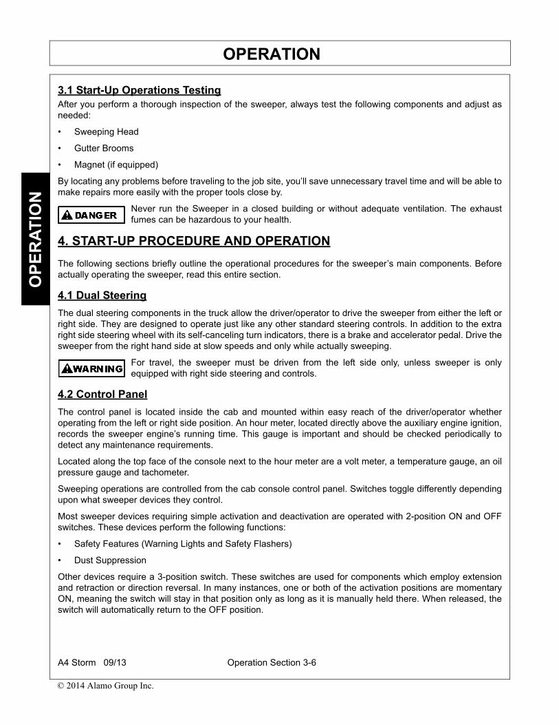
OPERATIONO
PE
RA
TIO
N
3.1 Start-Up Operations TestingAfter you perform a thorough inspection of the sweeper, always test the following components and adjust asneeded:
• Sweeping Head
• Gutter Brooms
• Magnet (if equipped)
By locating any problems before traveling to the job site, you’ll save unnecessary travel time and will be able tomake repairs more easily with the proper tools close by.
Never run the Sweeper in a closed building or without adequate ventilation. The exhaustfumes can be hazardous to your health.
4. START-UP PROCEDURE AND OPERATION
The following sections briefly outline the operational procedures for the sweeper’s main components. Beforeactually operating the sweeper, read this entire section.
4.1 Dual Steering
The dual steering components in the truck allow the driver/operator to drive the sweeper from either the left orright side. They are designed to operate just like any other standard steering controls. In addition to the extraright side steering wheel with its self-canceling turn indicators, there is a brake and accelerator pedal. Drive thesweeper from the right hand side at slow speeds and only while actually sweeping.
For travel, the sweeper must be driven from the left side only, unless sweeper is onlyequipped with right side steering and controls.
4.2 Control Panel
The control panel is located inside the cab and mounted within easy reach of the driver/operator whetheroperating from the left or right side position. An hour meter, located directly above the auxiliary engine ignition,records the sweeper engine’s running time. This gauge is important and should be checked periodically todetect any maintenance requirements.
Located along the top face of the console next to the hour meter are a volt meter, a temperature gauge, an oilpressure gauge and tachometer.
Sweeping operations are controlled from the cab console control panel. Switches toggle differently dependingupon what sweeper devices they control.
Most sweeper devices requiring simple activation and deactivation are operated with 2-position ON and OFFswitches. These devices perform the following functions:
• Safety Features (Warning Lights and Safety Flashers)
• Dust Suppression
Other devices require a 3-position switch. These switches are used for components which employ extensionand retraction or direction reversal. In many instances, one or both of the activation positions are momentaryON, meaning the switch will stay in that position only as long as it is manually held there. When released, theswitch will automatically return to the OFF position.
A4 Storm 09/13 Operation Section 3-6
© 2014 Alamo Group Inc.

OPERATIONO
PE
RA
TIO
N
4.3 Auxiliary EngineAlways check the auxiliary engine’s oil and coolant level before its first startup of the day. Follow themaintenance procedures outlined in ‘Maintenance Section’, as well as the maintenance procedures required inthe auxiliary engine manufacturer’s owner’s manual.
Look at the control panel to make certain that all switches are turned off.
Exception: If the optional beacon/strobe light switches are pre-set to ON, the lights will automatically flashwhen the auxiliary engine ignition switch is turned to ON.
Start the engine with the throttle in the idle position. The Schwarze A4 Storm sweepers are equipped with asafety shutdown system that will automatically shut the auxiliary engine off in the event of high coolanttemperature of low oil pressure.
Let the engine run for several minutes (until it warms up) before operating the sweeper.
Before starting the engine in a confined area, verify that proper outlet exhaust ventilationequipment is installed. Always use safety approved fuel storage and piping.
4.4 Dust Suppression System Operation
NOTE: When using a hydrant as a fill source, before actually filling the sweeper’s water reservoir allow thewater to run for a short period of time in order to flush out any sediment which may be trapped in the water line.
Using excess water to wet down leaves and other light debris tends to make them stick to the pavement.Sometimes neither the blast orifice nor the vacuum suction can remove such wet, lightweight debris.
Turn on the auxiliary engine. Toggle ON the console switch which controls the water pump motor. Toggle ONthe switches controlling the water functions desired.
NOTE: The sweeper head and hopper switch should always be ‘ON’ when sweeping, except during rainyconditions. Switches for the gutter brooms, spray bar and other water nozzles can be turned ‘ON’ and ‘OFF’ asneeded.
Turn the water console switches ‘ON’ and ‘OFF’ as the conditions change. The amount of time required toempty the water reservoirs depends on the number of switches in use and length of time they are used.
4.5 Gutter Broom Operation
Each gutter broom is controlled by a switch mounted on the control panel console. It operates in threepositions: ‘UP’, ‘OFF’ and ‘RUN’. To run and lower the gutter broom, push the switch down to the ‘RUN’position. The switch will stay in the run position until it is returned to the ‘OFF’ position. The broom will lowerand rotate while staying in contact with the sweeping surface. To raise the broom, push the switch to the ‘UP’position and hold it until the gutter broom has been retracted. This switch position uses a spring-loadedmomentary contact which will return to the ‘OFF’ position when released. To prevent damage to the hydraulicsystem when gutter broom is ‘UP’, the switch MUST return to ‘OFF’ position.
The side-to-side tilt of the broom disc can be manipulated to fit the pitch of the sweeping surface. This iscontrolled by a small turnbuckle within the broom arm. By manually adjusting the turnbuckle, the broom disccan be tilted to fit most sweeping surfaces. The turnbuckle may be replaced with an optional hydraulic tiltcylinder. By operating a MOM/OFF/MOM switch located on the console in the cab, the cylinder may beextended for retracted, which in turn, modifies the broom disc tilt. (The gutter broom tilt will only work when thegutter broom is running).
A4 Storm 09/13 Operation Section 3-7
© 2014 Alamo Group Inc.

OPERATIONO
PE
RA
TIO
N
To extend the life of the gutter broom bristles, we recommend they only be used when sweeping curbs. If theunit is equipped with dual steering, use the right hand side steering position when the right gutter broom isoperated.
When driving to or from job sites, or when the gutter broom is not in use, raise the gutter broom to the storedposition. Always store the gutter broom before traveling to provide the maximum ground clearance for safetransport.
For travel, the sweeper must be driven from the left side only, unless sweeper is onlyequipped with right side steering and controls.
4.6 Hand Hose Operation
The optional hand hose consists of a flexible hose with an aluminum nozzle on one end. It is mounted on ahinged transition plate on the right side of the hopper. To use the hand hose, release the rubber straps whichhold the hose to the side of the hopper. Open the hopper transition cover plate by turning the latch handle andswinging the cover plate back away from the hopper. Now the hand hose transition plate may be swung acrossthe opening in the hopper. Lock the hose plate in place by turning the latch handle.
If a very heavy concentration of debris requires removal, a block-off plate is needed to provide the desiredsuction. It is used to restrict the suction inlet, which increases the suction to the hand hose. Raise the hopperapproximately 1 inch and place the block-off plate between the suction inlet tube and hopper intake tube. Oncethe plate is in place, lower the hopper.
When using the hand hose in or around standing water, never hold the nozzle completely under the water’ssurface. Doing so will draw water up into the nozzle until the water pressure is equal to the suction within thehopper. When this occurs, the fan cannot draw air through the fan inlet and all suction is lost.
4.7 Magnet Operation
To engage the magnet, locate the console switch marked ‘MAGNET’. The sweeper ignition switch must beturned to the ‘ON’ position. Push up on this momentary switch to lower the magnet, holding it in the ‘UP’position for a few moments to be sure the magnet is fully lowered. The magnet will automatically stop theproper distance from the ground. Begin sweeping. When the magnet is no longer required, push down on themagnet switch, holding it in place until the magnet is fully raised. Objects picked up by the magnet must bemanually removed.
4.8 Camera System Operation
For camera system operation, see Camera System manufacturer’s manual included with Sweeper’s ManualSet.
A4 Storm 09/13 Operation Section 3-8
© 2014 Alamo Group Inc.
OPERATIONO
PE
RA
TIO
N
5. SWEEPING
To begin sweeping, start the auxiliary engine and set the throttle to the desired RPMs. Always use the lowestpossible throttle position to accomplish a desired sweeping task. Turn on the switch that controls the head andhopper water and any other part(s) of the dust suppression desired. Turn on all warning lights and beacons thatwill be used while sweeping.
A switch on the control console operates the sweeping head hydraulic cylinders. This switch has threepositions: ‘MOMENTARY ON/OFF/MOMENTARY ON’. To lower the sweeping head, push the switch into the‘DOWN’ position and hold it until the sweeping head is lowered. Release the switch. This switch uses a spring-loaded momentary contact which will return to ‘OFF’ position when released.
Drive the sweeper 1 to 15 MPH depending on maneuverability and the amount of debris to be picked up. Avoidsweeping over large sticks, pieces of cardboard or wood. These will clog the intake tube or damage the intakehose. When using the gutter broom, watch for large amounts of wire which may become tangled in the broom.Such objects should be picked up by hand and placed into the hopper through the side inspection doors.Beware of sweeping too closely to a curb-line or of catching the head runners in large holes. Catching a runnermay twist, warp or otherwise damage the pickup head, which is an expensive replacement item.
To raise the sweeping head, hold the switch in the ‘UP’ position. The sweeping head must be fully raised toprovide maximum ground clearance before traveling. Always check to ensure that the sweeping head iscompletely raised. This switch uses a spring-loaded momentary contact which will return to the ‘OFF’ positionwhen released.
Slow down for corners, parked cars and when near protruding posts and other solidobstacles that could cause damage to the sweeper or truck.
5.1 Sweeping Condition Control
A sweeping condition switch, labeled ‘LIGHT/HEAVY’ is located on the console. This switch controls a damperinside the fan housing which may be used to direct all of the airflow down the pressure hose and into the head,or to divert a portion of the airflow to an exhaust located directly beneath the fan housing.
For normal sweeping of curb and gutter streets, the damper door should be in the ‘HEAVY’ or just slightly openposition. This directs all or most of the airflow to the sweeping head, producing maximum blast in the sweepinghead’s blast orifice.
When sweeping leaves or other light material, the damper door should be in the ‘LIGHT’ position, allowingsome of the airflow to be exhausted. This decreases the volume of airflow through the blast orifice, reducingthe air pressure exerted against the rear of the front curtain and permits debris to pass beneath the frontcurtain more easily.
It is possible to sweep both light and heavy material in one pass. This is accomplished by opening and closingthe damper as you sweep. By practicing this method, you will become proficient with the various types ofmaterial.
A4 Storm 09/13 Operation Section 3-9
© 2014 Alamo Group Inc.

OPERATIONO
PE
RA
TIO
N
6. SHUTTING DOWN THE SWEEPER
When you are finished sweeping, set the sweeper engine throttle to idle. If the gutter brooms are being used,hold the gutter broom switches in the ‘UP’ position until the gutter brooms are fully retracted. Raise thesweeping head completely to provide the maximum ground clearance. Turn ‘OFF’ the dust suppressionsystem. The sweeper warning and flashing lights should be turned ‘OFF’ before traveling. Turn the sweeperengine key counterclockwise to the ‘OFF’ position to shut down the engine.
7. DUMPING THE HOPPER
For travel, the sweeper must be driven from the left side only, unless sweeper is onlyequipped with right side steering and controls.
Dump the hopper when it is full, or after you have finished sweeping for the day. Always dump on level groundand never attempt to dump over an open pit or dock. Back the sweeper up to a landfill, dumpster or othersuitable dumping area. Before raising the hopper, check for overhead clearance restrictions, put the truck in‘PARK’ and engage the emergency brake.
Always follow safe dumping practices.
To raise the hopper, push the switch into the position, the door will open first and then the hopper will raise,continue holding the switch until the hopper is completely raised.
If the hopper is raised for longer than the time required to dump, place the safety stops onthe dump cylinders. This applies whether the sweeper is being washed our, or for any othertime requiring that someone is in the ‘pinch area’.
Before lowering the hopper, remove the safetystops if used, and make certain the area under thehopper is clear. Hold the dump switch in the‘DOWN’ position to lower the hopper. This switchuses a spring-loaded momentary contact which willreturn to the ‘OFF’ position when released.
A4 Storm 09/13 Operation Section 3-10
© 2014 Alamo Group Inc.

OPERATIONO
PE
RA
TIO
N
8. END OF SHIFT CLEANUP / MAINTENANCE
Your new sweeper has been quality engineered to provide years of dependable service. By following theprocedures in this section, you will maximize the life of your sweeper by minimizing rust and part abrasion.
End of shift cleanup is a major factor in keeping your unit in like-new condition. Generally, a high volume ofwater cleans best; using a fire hose with a high-velocity nozzle is the quickest and simplest cleaning method.Other slower cleaning methods include the optional high volume wisdom nozzle or regular garden hose.
Exercise caution when cleaning moving mechanisms.
Before you begin this operation, verify that:
• The truck is out of gear
• The parking brake is engaged
NOTE: NEVER work under a raised hopper without placing the safety props into position. Allow at least half anhour at the end of a day’s sweeping to properly clean the unit.
1. While engines cool down at fast idle, toggle the following switches:
• Door: OPEN
• Hopper: UP
The rear door opens and the hopper raises.
2. On the cab console control panel, toggle the following switches:
• Left gutter broom: RUN
• Right gutter broom: RUN
The brooms drop and extend to their normal operating position.
3. After the brooms are lowered to the sweeping surface, toggle the following switches:
• Left gutter broom: OFF
• Right gutter broom: OFF
Do NOT raise the brooms.
4. Thoroughly hose down the brooms, center dirt deflector, sweeping head and hopper.
5. While the hopper is raised, wash the inside of the sweeping head’s suction hose.
6. On the cab console control panel, toggle these switches in the following sequence:
• Left gutter broom: UP
• Right gutter broom: UP
The gutter brooms retract to their travel positions.
7. Toggle the following switches:
• Door: CLOSE
• Hopper: DOWN
The rear door closes and the hopper lowers.
A4 Storm 09/13 Operation Section 3-11
© 2014 Alamo Group Inc.

OPERATIONO
PE
RA
TIO
N
8. Turn the auxiliary engine OFF.
9. Hose down the unit to completely rinse away all dirt and dust.
When you rinse off the auxiliary engine, do NOT spray water directly into the pre-cleaner.
10. Clean away debris that may have become wound around the gutter brooms.
11. Lubricate all daily lubrication points (See Section 4.4. ‘LUBRICATION SCHEDULES’)
12. Check the odometer and hour meter and perform any other needed lubrication.
13. In freezing weather, perform the following:
• Check both engines to make sure they contain enough environmentally safe antifreeze to safe guardagainst freezing before the next sweeping operation.
• Winterize the dust suppression system (See Section ‘DUST SUPPRESSION SYSTEMWINTERIZING’).
14. Inspect the sweeper for loose hardware, oil leaks, burned-out bulbs or fuses, tire wear and inflation, and soon. Adjust and repair, as needed.
9. QUICK REFERENCE OPERATING GUIDELINE
1. Check the truck engine and sweeper engine for the correct crankcase oil and coolant levels.
2. Fill the water storage tank.
3. Start the truck engine and check the control panel for the correct switch settings.
4. Crank the sweeper engine.
5. Before sweeping, let the engine warm up to operating temperature.
6. Turn on the water flow valves.
7. Turn ‘ON’ all warning lights and flashers
8. Lower the sweeping head to the pavement.
9. Throttle to desired sweeping RPMs.
10. Activate the dust suppression system.
11. If the gutter broom is to be used, turn it on.
12. Put the truck in gear and begin sweeping.
13. Avoid surface obstacles.
A4 Storm 09/13 Operation Section 3-12
© 2014 Alamo Group Inc.

OPERATIONO
PE
RA
TIO
N
10. SWEEPING ACCESSORIES
When operating the sweeper, you should carry along the following emergency equipment, as well as handtools to aid in removal of debris. The following is a suggested list which can be adapted to suit your specificneeds:
• Shovel
• Rake/Hoe
• Heavy Push Broom
• Tool Box and Tools
• Water Hose (to fill water tank)
• 2 to 5-Ton Hydraulic Bottle Jack
• Gas Can, 3-5 Gallon
• Backpack Blower (oil/gas mix)
• 2 Cycle Oil (Backpack)
• Quart Oil (sweeper/truck engine)
• Flashlight
• Safety Flares
• Spare Tire
• 2 to 3 Cans of Tire Puncture Repair
• Jumper Cable
• Fire Extinguisher
A4 Storm 09/13 Operation Section 3-13
© 2014 Alamo Group Inc.

OPERATIONO
PE
RA
TIO
N
11. TROUBLESHOOTING GUIDE
11.1 Sweeper
Problem Possible Cause Remedy
Loss of Vacuum- Sweeping too fast Slow downSweeper Not Picking Up Sweeper engine throttle position Throttle sweeper engine up
too lowHead not fully lowered Lower head completelyWorn flaps or skid plates out of a. Adjust side plateadjustment b. Replace flapsFaulty seal (fan, intake or door) Replace SealsTorn hose(s) Replace hose(s)Improper head spring tension Adjust head spring tensionBent or uneven drag arms Straighten or replace drag armBlast orifice too wide Be sure orifice is roughly ‘3/4’
Check for blockage in openingBlocked intake inlet Remove hose and clean debris
from intake inletBlocked screen Remove blockageBlocked intake tube Remove blockageLoose drive belt Tighten beltLow auxiliary engine RPM Seek serviceFan housing exhaust door bleeder Reset exhaust door bleederset wrongWorn Fan Replace fanFan not located properly within Adjust fan or back platefan housingHoles in hopper or fan housing Repair holesBlast orifice distance to sweeping Adjust skidsincorrect
Excessive Runner Wear- Improper head spring tension Adjust head spring tensionHead Not Gliding Properly Bent or uneven drag arms Straighten or replace drag arms
Improper side plate adjustment Adjust side platesBent head channel Straighten or replace head channel
Head Drifting Down Leaking sweeping head cylinder seal Rework sealsP. O. check valve stuck open Replace or clean
A4 Storm 09/13 Operation Section 3-14
© 2014 Alamo Group Inc.

OPERATIONO
PE
RA
TIO
N
Unusual Noise or Vibration Worn bearings Replace bearing(s)Fan out of balance Clean debris, rebalance or replace
fanFan shifted within housing Reposition fanLoose drive belt Tighten drive beltLoose bolts Tighten boltsFan blades worn or broken Replace fanEngine Locate, determine problem, repairLoose shaft bearing bolts Tighten bolts
11.2 Sweeper Engine
Problem Possible Cause Remedy
Sweeper Engine will not Dead Battery Charge or replace batteryStart Bad starter solenoid Replace solenoid
No power to console Find break in wire, reconnect,check breaker
No power to shutdown solenoid Check engine module wiringNo fuel Fill fuel systemImproper starting procedure Consult engine owner’s manualLoose battery connector Tighten connector
11.3 Automatic Shutdown System
For Troubleshooting the automatic shutdown system, see the Hewitt Troubleshooting Manual
11.4 Dust Suppression System
No Water Exiting Pump Out of water Refill tankSuction line clogged Clean ‘Y’ strainerAir leak in line Tighten plumbing
One Spray Nozzle Clogged strainer at nozzle Clean or replace nozzle strainerNot Working Crimped or clogged water line Uncrimp or unclog line
Nozzle valve not on Switch nozzle valve on
Only One Nozzle Clogged stainer at nozzle Clean ‘Y’ and then clean or replaceWill Come On nozzle strainer
No water Refill water systemWiring on solenoid Check power wire and ground,
repair as neededBad solenoid Replace solenoid
A4 Storm 09/13 Operation Section 3-15
© 2014 Alamo Group Inc.

OPERATIONO
PE
RA
TIO
N
Low Pressure Worn nozzle Replace with nozzle of proper sizeAir leak in inlet plumbing Disassemble, reseal and
reassembleRelief setting too low Adjust relief valve on pump.
Reference 414.5 for adjustment instructions
11.5 Other Symptoms
See Water Pump Manual.
11.6 Hydraulic System
Extreme Heat, Unusual Reservoir cap is not vented Replace cap with ventedNoise, Poor Performance equivalentfrom Pump Dirty Hydraulic oil Remove filters and clean or
replace; change oilLow oil level Check oil and fill as needed.Bad pump Repair or replace pumpBad hydraulic motor Rebuild or replace motorRestriction in the return filter Replace filter and hydraulic oil
if needed
Hydraulic System Will Mechanical pump not being Engine must be operating;Not Operate powered determine reason pump is not
being driven and repair accordinglyDirectional valve faulty or has Check electrical components orpoor ground replace valve
Major leak in hydraulic system Repair leakHydraulic pump pressure too low Adjust pump pressure (relief valve
in manifold)Leaking cylinders seals Replace seals or seek service
A4 Storm 09/13 Operation Section 3-16
© 2014 Alamo Group Inc.

OPERATIONO
PE
RA
TIO
N
11.7 Gutter Broom
Broom Disc Spins too Slow Sweeper engine throttle position Throttle up; sweeper engine speed is too slow
Fluid viscosity is too high for Replace with lighter weight oiloperating temperatureOutside temperature low Run auxiliary engine longer before
using gutter broom to warm up hydraulic oil
Broom hydraulic motor is bad Rebuild or replace motorToo much down pressure Adjust down pressure
Broom Hits Frame Inner broom cylinder stroke is Screw rod end toward cylinder totoo short lengthen strokeSpring tension too light Adjust spring tension
Debris Trails Between Improper broom head adjustment Adjust broom head tiltBroom Disc and Side of Broom arm with optional GEO Adjust GEOSweeping Head extended too far
Broom bristles worn Replace Bristles
Broom Disc Stalls in Heavy Pressure to broom motor too low Adjust relief pressureDebris Motor or pump seal leaking Seek service
Too much down pressure Adjust
Broom Flings Debris Broom disc tilt angle adjusted Adjust broom disc tilt angleBack Into Gutter too flat
Broom Flings Debris Tilt angle of broom head too great Adjust broom headAcross Street Center flap worn or damaged Replace
Broom Spins But Will The inside of the cylinder’s hydraulic Clear blockageNot Extend/Retract hose or fitting is blocked
Directional valve malfunctioning Check directional valve. Replaceif needed.
Lock valve not functioning Clean or replace
Broom Operates But Switch or directional valve wire Check wiring.Will Not Lift loose or bad connection
Block solenoid valve Replace valveLeaking cylinder seals (fluid loss Replace sealsout of port)Mechanical bind Check broom hardware for binds
A4 Storm 09/13 Operation Section 3-17
© 2014 Alamo Group Inc.

OPERATIONO
PE
RA
TIO
N
Broom Spins But Will Solenoid valve’s electrical circuit Complete circuitNot Lower incomplete
Bad solenoid valve cartridge Replace cartridge(Lock Valve)Mechanical bind Check broom hardware for binds
Broom Raises But Leaks Solenoid valve stuck open Clean valve or replaceDown Immediately (Lock Valve)
Leaking cylinder seals (fluid loss out Replace sealsof port vent)
Broom Operates But Disc Bad broom motor Service or replace motorDoes Not Spin Directional valve not operating Repair or replace directional valve
Broom Drops But Will Directional valve’s electrical circuit Complete circuitNot Otherwise Operate is incomplete
Directional valve ports blocked Seek serviceBad pump or motor Service or replace pimp or motor
Broom Will Not Drop or Tripped circuit breaker Reset circuit breakerOtherwise Operate Bad Switch Replace switch
Directional valve wiring bad Check directional valve wiringcircuit
A4 Storm 09/13 Operation Section 3-18
© 2014 Alamo Group Inc.

Maintenance Section 4-1
© 2014 Alamo Group Inc.
MAINTENANCE SECTION
MAINTENANCEM
AIN
TE
NA
NC
E
1. PARTS INFORMATIONSchwarze sweepers are carefully designed and built with quality materials and should be maintained usingquality parts. These parts are made and tested to Schwarze specifications. Non-genuine “will fit” parts do notconsistently meet these specifications. The use of “will fit” parts may reduce the sweepers performance, voidwarranties, and present a safety hazard. Use genuine Schwarze sweeper parts for economy and safety.
2. GENERAL MAINTENANCEIn this part of the Schwarze A4 Storm manual, we include checking, adjustment and/or replacementprocedures for all major sweep systems and devices.
For some systems and devices, such as daily examination of the ‘Y’ strainer, maintenance is regular andongoing. For others, we include a beginning statement to tell you when adjustment or replacement isnecessary. For example, when water flow is restricted at the right or left gutter broom, the dust suppressionsystem nozzles should be cleaned or replaced.
For many components, we also include a table of maintenance task and identify the section(s) of the manual toaccess for related procedures.
2.1 Maintenance LogsTo help you keep your Schwarze A4 Storm in top operating condition, we have provided Sweeper and TruckPre-Operation Inspection Sheets to be used before every sweeper operation. These forms can be found in thebeginning of the Operation Section of this Operator’s Manual. Please make copies and store them in a file tokeep them accessible and clean.
You complete each form by:
• Recording the sweeper identification number• Recording the date• Checking off inspection/maintenance tasks• Signing your name
Additionally, each form has a Comments Section for:
• Providing detailed information on a listed item• Noting information about items not listed• Noting additional concerns• Specifying a needed replacement part• Recording the date a replacement part is ordered
The completed forms can be complied in a notebook. Over time this will come to represent a comprehensiveinspection maintenance record for your sweeper.
A4 Storm 09/13 Maintenance Section 4-2
© 2014 Alamo Group Inc.
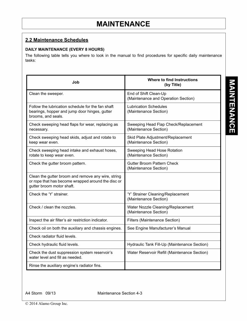
MAINTENANCEM
AIN
TE
NA
NC
E
2.2 Maintenance Schedules
DAILY MAINTENANCE (EVERY 8 HOURS)
The following table tells you where to look in the manual to find procedures for specific daily maintenancetasks:
JobWhere to find Instructions
(by Title)
Clean the sweeper. End of Shift Clean-Up (Maintenance and Operation Section)
Follow the lubrication schedule for the fan shaft bearings, hopper and jump door hinges, gutter brooms, and seals.
Lubrication Schedules (Maintenance Section)
Check sweeping head flaps for wear, replacing as necessary.
Sweeping Head Flap Check/Replacement(Maintenance Section)
Check sweeping head skids, adjust and rotate to keep wear even.
Skid Plate Adjustment/Replacement(Maintenance Section)
Check sweeping head intake and exhaust hoses, rotate to keep wear even.
Sweeping Head Hose Rotation(Maintenance Section)
Check the gutter broom pattern. Gutter Broom Pattern Check(Maintenance Section)
Clean the gutter broom and remove any wire, string or rope that has become wrapped around the disc or gutter broom motor shaft.
Check the ‘Y’ strainer. ‘Y’ Strainer Cleaning/Replacement(Maintenance Section)
Check / clean the nozzles. Water Nozzle Cleaning/Replacement(Maintenance Section)
Inspect the air filter’s air restriction indicator. Filters (Maintenance Section)
Check oil on both the auxiliary and chassis engines. See Engine Manufacturer’s Manual
Check radiator fluid levels.
Check hydraulic fluid levels. Hydraulic Tank Fill-Up (Maintenance Section)
Check the dust suppression system reservoir’s water level and fill as needed.
Water Reservoir Refill (Maintenance Section)
Rinse the auxiliary engine’s radiator fins.
A4 Storm 09/13 Maintenance Section 4-3
© 2014 Alamo Group Inc.

MAINTENANCEM
AIN
TE
NA
NC
E
OCCASSIONAL MAINTENANCE
The following table tells you where to look in the manual to find procedures for specific occasional maintenancetasks:
3. CLEANINGCleaning is an important part of any maintenance program because it extends the life of the sweeper byreducing rust and abrasion.
For a general description of cleaning procedures see Operation Section of Manual, ‘END OF SHIFT CLEAN-UP / MAINTENANCE.’
4. SWEEPER FLUID MAINTENANCE
4.1 Auxiliary Engine Oil Refer to your auxiliary engine Owner’s Manual for the manufacturer’s suggested oil type and oil changeschedule. To drain the engine oil pan, use the engine oil drain hose. This hose, which resembles the hydraulichoses, runs from the center of the oil pan, out the right side of the engine skid and is usually looped around tothe front of the engine skid for storage. By unscrewing and removing the JIC plug in the end of the hose, the oilmay be drained into a container. Be sure to dispose of the used oil properly, recycling it if possible.
4.2 Auxiliary Engine Cooling SystemRefer to your auxiliary engine Owner’s Manual for cooling system care and maintenance. When replacing yourengine’s coolant, be sure to dispose of the old coolant properly.
Job Where to find Instructions
(by Title)
Check fan and fan housing liner for wear. Fan Housing Check (Maintenance Section)
Check fan drive belt for wear and tension. Drive Belt Tension Adjustment(Maintenance Section)
Replace the gutter broom bristles when they become worn to approximately 8 inches in length.
Gutter Broom Bristles Replacement(Maintenance Section)
Winterize the dust suppression system. Dust Suppression System Winterizing(Maintenance Section)
A4 Storm 09/13 Maintenance Section 4-4
© 2014 Alamo Group Inc.

MAINTENANCEM
AIN
TE
NA
NC
E
4.3 Hydraulic System
The hydraulic oil level should be maintained suchthat it is kept at the full mark as measured with thehopper down. Check by using the sight level gauge,which is located on the left side of the reservoir.Change the hydraulic oil and filter after the first 500hours of operation, then every 2000 hoursthereafter.
If the hydraulic fluid becomes cloudy, water hascontaminated the system and the hydraulic fluidneeds to be changed (after determining the sourceof the water contamination and correcting it). If thesweeping unit is operated in particularly dustyconditions, the hydraulic filters will need to bechanged more often.
For detailed maintenance procedures of thehydraulic system, See Section “HYDRAULICSYSTEM MAINTENANCE.’
5. LUBRICATION SCHEDULERefer to the following table for correct sweeper lubrication.
Item Frequency Lubricant
1. Dump Door Hinges Monthly Grease with lithium-based grease.
2. Hopper/Frame Hinge Monthly Grease with lithium-based grease.
3. Gutter Broom Arm U-Joint 120 Hours of Operation
Grease with lithium-based grease.
4. Fan Shaft Bearings 250 Hours of Operation
Grease with lithium-based grease, one pump from a hand-operated gun. DO NOT OVER-GREASE OR USE A POWER GUN
5. Fan Seal, Intake Seal, and Rear Door Seal
As Required Lubricate with a rubber protectant or grease to prevent drying and loss of resilience.
A4 Storm 09/13 Maintenance Section 4-5
© 2014 Alamo Group Inc.

MAINTENANCEM
AIN
TE
NA
NC
E
6. FILTERS
Because of the dusty conditions under which a sweeper operates, filters are considered a priority maintenanceitem. Failure to properly follow filter change schedules may result in poor performance or costly componentreplacement.
6.1 Auxiliary Engine FiltersThe auxiliary engine has three filters: a fuel filter, anoil filter and a dual element air filter. At a minimum,all filters should be changed according to the enginemanufacturer’s warranty recommendations. Werecommend that the aux. engine service dailymaintenance recommendations be followed.
The air filter has a built-in air restriction indicator.When the air filter becomes clogged and needsservice, a window on the air restriction indicatorchanges color. Depending upon the type of airrestriction indicator used, this color change may befrom clear to red, clear to yellow or yellow to red.The air restriction indicator is normally located on ornear the auxiliary engine’s air filter canister oroptionally by remote in the truck cab on the console.
Do not clean air filter with high pressure air.
Clean or change the air filter only when the air restriction indictor’s ‘Need to Service’window has changed colors. Serious engine damage can occur as a result of air cleanerover-servicing.
For air filter change and service information, please see the Owner’s Manual for the auxiliary engine.
6.2 Hydraulic Tank FiltersThe hydraulic tank employs two filters, a suction and a return, to remove foreign particles from the hydraulic oilthat might cause failure in the hydraulic system’s components. For detailed maintenance procedures on thesetwo filters, See Section, ‘HYDRAULIC SUCTION STRAINER / REPLACEMENT’ and Section, ‘HydraulicReturn Filter.’
Dust Suppression System Filter
Water filter maintenance is an important part in keeping the sweeper’s water system functioning properly. TheY strainer should be emptied and its strainer screen flushed and cleaned daily. However, the frequency of filtercleaning varies and largely depends on the purity of the fill source’s water.
For detailed maintenance procedures on the ‘Y’ strainer filter, See Section, ‘Y Strainer Cleaning/Replacement.’
THE AIR FILTER’S AIR RESTRICTION INDICATOR
A4 Storm 09/13 Maintenance Section 4-6
© 2014 Alamo Group Inc.

MAINTENANCEM
AIN
TE
NA
NC
E
7. SEALS
It is important that the sweeper’s seals on the fan housing be kept in the best condition possible. These includethe seals on the suction hose inlet, around the hopper’s inspection door opening and on the rear door. Pickuppower is vacuum-dependent, so a tight seal can make a significant difference in pickup ability. Maintainresilience by keeping the seals well lubricated with a good grade of petroleum-based jelly or grease.
Lubrication of the side inspection door seals is unnecessary.
For longer seal life, when the sweeper is parked for an extended period of time, leave the dump door and allinspection doors open and raise the hopper several inches so their seals can regain their shape.
Eventually the seals will become worn or non-resilient and must be replaced.
7.1 Seal Replacement1. Use a gasket scraper, putty knife or screwdriver to remove the seal from its sweeper component. Get the
metal surface as clean as possible. Be sure it is free of all dirt, old glue, and seal material.
2. Liberally apply a coat of weather-strip-type adhesive onto the new seal and body component. Allow theadhesive to set up for several minutes (follow the adhesive manufacturer’s instructions) and then put thenew seal in place.
8. HOPPERThe hopper is one of the central components of the A4 Storm sweeper. To ensure the longest possible usefullifetime, it is extremely important to clean it after each shift and to let it air dry with the hopper up wheneverpossible.
FAN SEAL INTAKE SEAL
A4 Storm 09/13 Maintenance Section 4-7
© 2014 Alamo Group Inc.

MAINTENANCEM
AIN
TE
NA
NC
E
9. AUXILIARY ENGINE
The auxiliary engine is equipped with a Hewittelectronic shutdown.
For more information, see the HewittTroubleshooting Section of the Manual.
10. DRIVETRAIN COMPONENT MAINTENANCEThe following sections deal with adjustments, replacement and lubrication of mechanical portions of thedrivetrain.
10.1 Drive Belt Tension AdjustmentOn the rear of the auxiliary engine is the belt whichdrives the fan shaft. Check the belt tensionperiodically. This is accomplished by pressing downon the belt halfway between the two pulleys. With50-75 lbs. of pressure (the approximate equivalentof very firm pressure from on it from your thumb),the belt should deflect about 1/4” - 3/8”. An averagebelt, over the course of its life, will stretch slightlyand the belt will need adjustment. This will beespecially true during the first 50-75 hours ofoperation.
Adjustment:
The auxiliary engine, along with its engine skid, canbe moved in the direction of the fan shaft (to loosenor remove the belt) or away from the fan shaft (totighten the belt).
1. Remove the belt guard.
2. Loosen (Do Not Remove) the bolt which holdseach of the four outer corners of the engine skidto the top of the power module platform.
3. Locate the threaded rods known as jackscrews.
HEWITT ENGINE SHUTDOWN
WITH 30 LBS OF PRESSURETHE BELT SHOULD DEFLECT 1/2”
A4 Storm 09/13 Maintenance Section 4-8
© 2014 Alamo Group Inc.
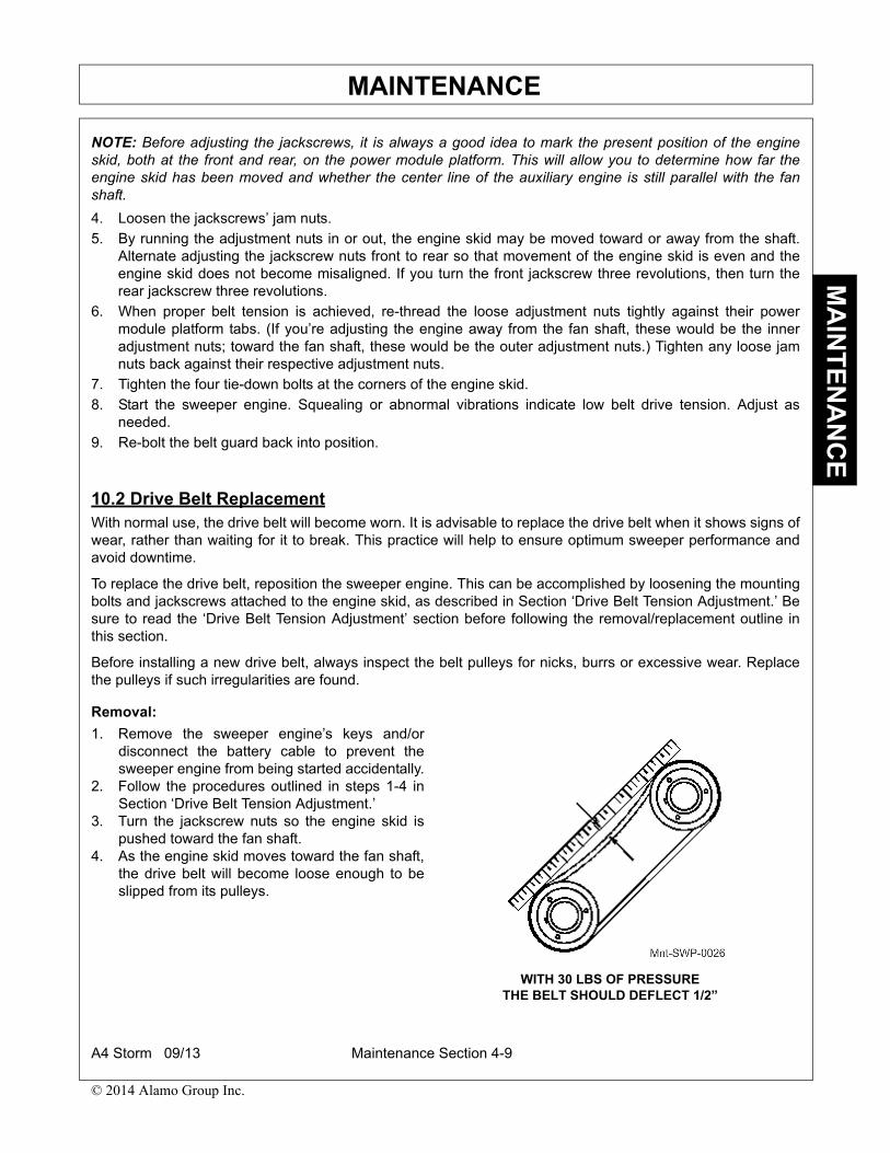
MAINTENANCEM
AIN
TE
NA
NC
E
NOTE: Before adjusting the jackscrews, it is always a good idea to mark the present position of the engineskid, both at the front and rear, on the power module platform. This will allow you to determine how far theengine skid has been moved and whether the center line of the auxiliary engine is still parallel with the fanshaft.
4. Loosen the jackscrews’ jam nuts.
5. By running the adjustment nuts in or out, the engine skid may be moved toward or away from the shaft.Alternate adjusting the jackscrew nuts front to rear so that movement of the engine skid is even and theengine skid does not become misaligned. If you turn the front jackscrew three revolutions, then turn therear jackscrew three revolutions.
6. When proper belt tension is achieved, re-thread the loose adjustment nuts tightly against their powermodule platform tabs. (If you’re adjusting the engine away from the fan shaft, these would be the inneradjustment nuts; toward the fan shaft, these would be the outer adjustment nuts.) Tighten any loose jamnuts back against their respective adjustment nuts.
7. Tighten the four tie-down bolts at the corners of the engine skid.
8. Start the sweeper engine. Squealing or abnormal vibrations indicate low belt drive tension. Adjust asneeded.
9. Re-bolt the belt guard back into position.
10.2 Drive Belt ReplacementWith normal use, the drive belt will become worn. It is advisable to replace the drive belt when it shows signs ofwear, rather than waiting for it to break. This practice will help to ensure optimum sweeper performance andavoid downtime.
To replace the drive belt, reposition the sweeper engine. This can be accomplished by loosening the mountingbolts and jackscrews attached to the engine skid, as described in Section ‘Drive Belt Tension Adjustment.’ Besure to read the ‘Drive Belt Tension Adjustment’ section before following the removal/replacement outline inthis section.
Before installing a new drive belt, always inspect the belt pulleys for nicks, burrs or excessive wear. Replacethe pulleys if such irregularities are found.
Removal:
1. Remove the sweeper engine’s keys and/ordisconnect the battery cable to prevent thesweeper engine from being started accidentally.
2. Follow the procedures outlined in steps 1-4 inSection ‘Drive Belt Tension Adjustment.’
3. Turn the jackscrew nuts so the engine skid ispushed toward the fan shaft.
4. As the engine skid moves toward the fan shaft,the drive belt will become loose enough to beslipped from its pulleys.
WITH 30 LBS OF PRESSURETHE BELT SHOULD DEFLECT 1/2”
A4 Storm 09/13 Maintenance Section 4-9
© 2014 Alamo Group Inc.
MAINTENANCEM
AIN
TE
NA
NC
E
Replacement:
1. Inspect the pulley grooves for burrs and other irregularities that may cause abnormal belt wear. Correct asrequired.
2. Slip the replacement belt into position.3. Tighten the jackscrew nuts so the engine skid is pulled away from the fan shaft.4. Continue to tighten until the belt has 1/2” deflection between the pulleys using 30 lbs. of pressure (roughly
the equivalent of pressing down on the belt with your thumb).5. Check the alignment of the pulleys, using a string or straight edge, from the face of one pulley to the face of
the other. This will allow you to determine whether the pulleys are in line with each other.
NOTE: For slight misalignment, the pulleys may be repositioned on their respective shafts. If greateradjustment is needed than pulley repositioning can achieve, the entire engine/engine skid assembly mustbe moved to obtain alignment. The slotted tie-down holes of the engine skid allow a limited amount offorward-back movement.
6. Once proper pulley alignment is achieved, run the jam nuts back against their respective jackscrew nuts.7. Tighten the four tie-down bolts at the corners of the engine skid.
NOTE: Once the hour tie-down bolts have been tightened, release the tension on the jackscrews.
8. Start the sweeper engine. Squealing or abnormal vibrations indicate low belt drive tension. Adjust asneeded.
9. Re-bolt the belt guard back into position.
10.3 Fan Shaft Bearing LubricationThe two pre-lubricated bearings on the fan shaft should be re-lubricated after 250 hours of operation (check thesweeper engine’s hour meter and the lubrication chart). Use a lithium-based grease conforming to NLGINumber 2 consistency. It must be free from chemical impurities such as free acid and free alkali, as well asphysical impurities such as dust, rust, metal and other abrasive particles. This light-viscosity, low-torque greaseis selected because of its water-insoluble rust inhibitors and operating temperatures that make it chemicallyand mechanically stable. Its normal operating temperature range of -30° to +200° Fahrenheit is ideal forsweeper operations. However, it can operate intermittently at temperatures of up to +250° Fahrenheit,providing maximum bearing protection.
Always use a hand-operated grease gun to grease the bearing. Use only one pump of grease or until a smallbead forms around the bearing seal. This bead acts as an indicator of adequate lubrication and provides aprotective seal which prevents foreign material from entering the bearing where it would damage the races.There is generally a slight rise in operating temperature (10-30° Fahrenheit) after re-lubricating the bearing.This temperature rise will continue until the grease stabilizes in the bearing chamber.
Lubrication:
Do NOT get loose clothing, jewelry, etc., caught in rotating equipment.
1. Prior to lubricating, run the auxiliary engine in order to heat up the old grease. When the bearing greasehas warmed, turn the auxiliary engine off and remove the keys.
2. Using a hand-operated grease gun, slowly apply one pump of grease to the bearing (equivalent toapproximately 1/4 ounce of grease) or until a slight bead forms around the bearing seals.
NOTE: Never use more than one pump of grease, and do not grease the bearings more often than every 250hours of operation. Over-greasing the bearing will cause the bearing to overheat and fail.
Lubrication should never differ from the prescribed procedure or schedule. Bearing life isshortened by over-lubrication - either by greasing too frequently or too excessively.
A4 Storm 09/13 Maintenance Section 4-10
© 2014 Alamo Group Inc.

MAINTENANCEM
AIN
TE
NA
NC
E
10.4 Fan Shaft Bearing Replacement
With proper lubrication, and under normal operating conditions, the bearings should last approximately 2500hours (check the auxiliary engine’s hour meter). Premature bearing failure is often due to improper lubricationprocedures. If bearing replacement is occurring more frequently than normal, you should review the bearinglubrication procedure outlined in this manual.
Bearing failure is accompanied by abnormal noise, vibration and/or the slinging of grease caused by rupturedbearing seals. Worn bearings should be replaced immediately to prevent damage to other sweepercomponents. The severing of the fan shaft, during the fan shaft bearing removal procedures necessitates areplacement fan shaft. Usually, accompanying drive belts, pulleys and bushings are also replaced. Thisensures proper performance and eliminates repetitive maintenance and downtime.
Disassembly:
1. Raise the hopper and place safety chocks over the dump cylinders.
2. Lock out the sweeper to prevent accidental starting of the sweeper engine.
3. Remove the bolts and washers from around the fan housing backing plate.
4. Pull the backing plate free and place in a secure location.
5. Remove the 3 bolts from the fan bushing.
6. Chase the threaded holes in the bushing with a bottoming tap.
7. Insert two of the removed bolts in the threaded holes in the bushing.
8. Tighten the bolts evenly, alternating from one to the other. This will push the fan off of the fan bushing.
9. Use a gear puller to remove the fan bushing from the fan shaft, if necessary.
10. Remove the fan and place in secure location.
11. Remove hydraulic lines attached to hydraulic tank. Plug and cap all openings.
12. Remove bolts holding tank to power module and remove hydraulic tank.
13. Remove shaft guard.
14. Relieve belt tension by following steps 1 through 3 ‘Removal’ in Section ‘Drive Belt Replacement’
15. Remove cover plate from bearing side of fan housing.
16. Unbolt fan shaft bearings from power module and remove fan shaft, bearings, pulley and belt as anassembly.
17. Loosen lock collars on fan shaft bearings.
18. Using emery cloth, clean up fan end of the fan shaft.
19. Measure from the fan end of the fan shaft to the bearing face and note this measurement.
20. Remove bearings from shaft. It is likely that the fan bearings will be unable to be removed from the fanshaft. If this is the case, cut the shaft to remove the pulley and bushing.
21. The pulley bushing removal is the same as the fan bushing removal in steps 5-9.
22. Inspect the pulley, bushing and belt for wear and replace if necessary.
Replacement:
1. Assemble the bearings, pulley, bushing and belt onto the fan shaft.
2. Slide the rear bearing onto the shaft to the measurement taken earlier and lock to the fan shaft.
3. Lock the front bearing to the fan shaft, flush with the end of the shaft.
4. Assemble the pulley and bushing loosely onto the shaft to allow alignment with the lower pulley.
5. Ensure bearing mounts are clean and free of foreign material and place fan shaft assembly onto thebearing mounts.
6. Center bolts in slots of bearing mounts and tighten.
A4 Storm 09/13 Maintenance Section 4-11
© 2014 Alamo Group Inc.

MAINTENANCEM
AIN
TE
NA
NC
E
7. Install deflector and bearing backing plate.
8. Slide belt over bottom pulley.
9. Tension belt and align pulleys, tightening the upper pulley bushing when proper alignment is achieved.
10. Inspect fan housing liner and replace with new one if cords are showing. Check elevator bolts for wear andreplace if worn. Genuine Schwarze replacement liner kits are pre-punched and come with hardwareneeded to install.
11. Install fan, following steps outlined under ‘REPLACEMENT’ in ‘Fan Replacement’ Section of the Manual.
12. Replace hydraulic tank and replace hydraulic lines removed.
13. Reconnect batteries.
14. Remove safety props, lower hopper and check sweeper for proper operation.
11. FAN HOUSINGThe fan housing directs the flow of air from the fanto the sweeping head. To provide the maximumperformance from the fan, the fan housing and drivecomponents should be checked for wear regularly.When signs of wear occur on a component, replaceit as soon as possible.
11.1 Fan Housing CheckWhen air is drawn from the hopper into the fan housing, a small amount of fine dust is also pulled into the fanchamber. This fine dust wears the fan blades, fan housing liner, and the heads of the fan housing liner bolts.Over a period of time, the sandblasting effect of this dust will cause enough wear to these components thatthey must be replaced. Failure to replace them is dangerous and can be very costly, since a worn fan blade canbreak and damage the inside of the fan housing. Worn liner bolts may allow the fan housing liner to sag andcause damage to the fan as well as to its shaft and bearings. A worn liner permits the abrasive effect of theairstream to reach the walls of the fan housing, which is an expensive replacement item.
Inspection:
1. Raise the hopper and place safety stops over the dump cylinders.2. Remove the keys from the ignition and disconnect the battery cable to prevent the engine from accidentally
starting.3. Remove the back plate.4. Using a flashlight, inspect the fan blades, fan bushing, fan housing liner bolts and the fan housing liner for
wear.5. If no excess wear or abnormal wear is evident, replace the back plate, remove safety props, and reconnect
the battery cables.
FAN HOUSING
A4 Storm 09/13 Maintenance Section 4-12
© 2014 Alamo Group Inc.

MAINTENANCEM
AIN
TE
NA
NC
E
11.2 Fan ReplacementIf a worn fan is causing reduced sweeping efficiency, it should be replaced promptly. The fan shaft bearingshave a life expectancy of roughly 2500 hours. When a fan replacement becomes necessary near the end of thebearing’s life expectancy, the bearings should likewise be replaced. Replacing both components will eliminatethe need to perform two, identical labor operations, and avoid downtime in close succession.
Exceptions to fan/bearing replacement:
• If you sweep in extremely sandy conditions, or do not use the sweeper’s water system, you may have toreplace fans more often than bearings.
• If the proper bearing lubrication procedures aren’t followed, you may have to replace bearings more oftenthan fans.
Disassembly:
1. Raise the hopper and place the safety stopsover the dump cylinders.
2. Remove the engine’s keys and disconnect thebattery cables to prevent the engine from beingaccidentally started.
3. Remove the 5/16” lock nuts and washers fromaround the back cover plate and lift it off.
4. Remove the 3/8” bolts and lock washers fromthe fan’s bushing.
5. Reinsert two 3/8” bolts into the tapped holes ofthe bushing. Tighten these bolts evenly. This willpush the fan off the bushing.
6. Use a gear puller to remove the bushing fromthe fan shaft.
7. Remove the fan from the fan shaft and fanhousing.
8. While the fan is out, check the rubber liner insidethe fan housing. If signs of excessive wear areapparent, replace the liner. Failure to replace therelatively inexpensive liner could result in havingto replace the more expensive fan housing later.
FAN BUSHING REMOVAL
A4 Storm 09/13 Maintenance Section 4-13
© 2014 Alamo Group Inc.
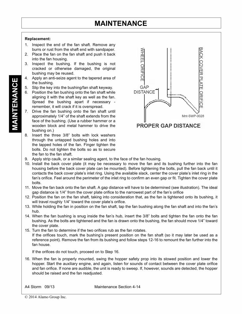
MAINTENANCEM
AIN
TE
NA
NC
E
Replacement:
1. Inspect the end of the fan shaft. Remove anyburrs or rust from the shaft end with sandpaper.
2. Place the fan on the fan shaft and push it backinto the fan housing.
3. Inspect the bushing. If the bushing is notcracked or otherwise damaged, the originalbushing may be reused.
4. Apply an anti-seize agent to the tapered area ofthe bushing.
5. Slip the key into the bushing/fan shaft keyway.6. Position the fan bushing onto the fan shaft while
aligning it with the shaft key as well as the fan.Spread the bushing apart if necessary -remember, it will crack if it is overspread.
7. Drive the fan bushing onto the fan shaft untilapproximately 1/4” of the shaft extends from theface of the bushing. (Use a rubber hammer or awooden block and metal hammer to drive thebushing on.)
8. Insert the three 3/8” bolts with lock washersthrough the untapped bushing holes and intothe tapped holes of the fan. Finger tighten thebolts. Do not tighten the bolts so as to securethe fan to the fan shaft.
9. Apply strip caulk, or a similar sealing agent, to the face of the fan housing.10. Install the back cover plate (it may be necessary to move the fan and its bushing further into the fan
housing before the back cover plate can be mounted). Before tightening the bolts, pull the fan back until itcontacts the back cover plate’s inlet ring. Using the available slack, center the cover plate’s inlet ring in thefan’s orifice. Feel around the perimeter of the inlet ring to confirm an even gap or fit. Tighten the cover platebolts.
11. Move the fan back onto the fan shaft. A gap distance will have to be determined (see illustration). The idealgap distance is 1/4” from the cover plate orifice to the narrowest part of the fan’s orifice
12. Position the fan on the fan shaft, taking into consideration that, as the fan is tightened onto its bushing, itwill travel roughly 1/4” toward the cover plate’s orifice.
13. While holding the fan in position on the fan shaft, tap the fan bushing along the fan shaft and into the fan’shub.
14. When the fan bushing is snug inside the fan’s hub, insert the 3/8” bolts and tighten the fan onto the fanbushing. As the bolts are tightened and the fan is drawn onto the bushing, the fan should move 1/4” towardthe cover plate.
15. Turn the fan to determine if the two orifices rub as the fan rotates. If the orifices touch, mark the bushing’s present position on the fan shaft (so it may later be used as areference point). Remove the fan from its bushing and follow steps 12-16 to remount the fan further into thefan house.
If the orifices do not touch, proceed on to Step 16.
16. When the fan is properly mounted, swing the hopper safety prop into its stowed position and lower thehopper. Start the auxiliary engine, and again, listen for sounds of contact between the cover plate orificeand fan orifice. If none are audible, the unit is ready to sweep. If, however, sounds are detected, the hoppershould be raised and the fan readjusted.
A4 Storm 09/13 Maintenance Section 4-14
© 2014 Alamo Group Inc.
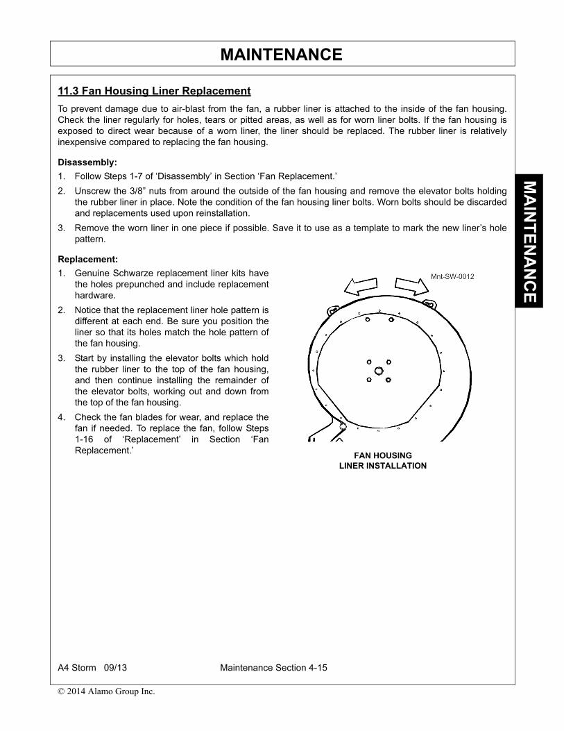
MAINTENANCEM
AIN
TE
NA
NC
E
11.3 Fan Housing Liner Replacement
To prevent damage due to air-blast from the fan, a rubber liner is attached to the inside of the fan housing.Check the liner regularly for holes, tears or pitted areas, as well as for worn liner bolts. If the fan housing isexposed to direct wear because of a worn liner, the liner should be replaced. The rubber liner is relativelyinexpensive compared to replacing the fan housing.
Disassembly:
1. Follow Steps 1-7 of ‘Disassembly’ in Section ‘Fan Replacement.’
2. Unscrew the 3/8” nuts from around the outside of the fan housing and remove the elevator bolts holdingthe rubber liner in place. Note the condition of the fan housing liner bolts. Worn bolts should be discardedand replacements used upon reinstallation.
3. Remove the worn liner in one piece if possible. Save it to use as a template to mark the new liner’s holepattern.
Replacement:
1. Genuine Schwarze replacement liner kits havethe holes prepunched and include replacementhardware.
2. Notice that the replacement liner hole pattern isdifferent at each end. Be sure you position theliner so that its holes match the hole pattern ofthe fan housing.
3. Start by installing the elevator bolts which holdthe rubber liner to the top of the fan housing,and then continue installing the remainder ofthe elevator bolts, working out and down fromthe top of the fan housing.
4. Check the fan blades for wear, and replace thefan if needed. To replace the fan, follow Steps1-16 of ‘Replacement’ in Section ‘FanReplacement.’
FAN HOUSINGLINER INSTALLATION
A4 Storm 09/13 Maintenance Section 4-15
© 2014 Alamo Group Inc.

MAINTENANCEM
AIN
TE
NA
NC
E
12. SWEEPING HEAD
The sweeping head is dependent upon forced airand vacuum to achieve debris pickup. Withoutproper maintenance and replacement of parts dueto normal wear, the sweeping head cannot providethe desired sweeping results.
12.1 Skid Plate Adjustment / ReplacementThe skid plate on the Schwarze A4’s sweepinghead is designed for durability and low maintenanceTungsten carbide inserts in the runners ensure along life to a part that must, by the nature of its job,endure extreme punishment. Replace the skid platewhen its runner is 80% worn through.
Removal / Replacement:
1. Locate the skid plates on either side of thesweeping head. Note that studs, welded to thesweeping head, protrude through slots in theskid plates. The skid plates are held in placeagainst the head by the nuts and washers onthese studs.
2. With the sweeping head raised, remove theskid plate’s nuts and washers and set themaside for later use.
3. Pull the old skid from the side of the sweeping head and replace it with the new skid plate.
4. Remount the nuts and washers that were removed earlier. Screw them down against the skid plate, but donot tighten them until the new skid plate is in the proper position.
Remember: Whenever skid plate adjustment is necessary, the blast orifice must remain 1-1/2” to 2” from thesweeping surface. Less than 1-1/2”, and the air stream becomes choked down. More than 2” and the blastvelocity of the air striking the sweeping surface is lost.
Never adjust the skid plates to extend the life of the flaps. When the flaps can no longer maintain a satisfactoryseal, they should be replaced. Adjusting the skid plates may affect the sweeping efficiency due to the change inblast orifice-to-ground distance.
STANDARD SWEEPING HEADSKID PLATE
A4 Storm 09/13 Maintenance Section 4-16
© 2014 Alamo Group Inc.

MAINTENANCEM
AIN
TE
NA
NC
E
Adjustment:
Do not adjust the skid plates so far up that the head’s blast orifice is less than 2” from thesweeping surface.
1. Raise the sweeping head and locate the skid plates on either side.
2. Loosen the 5/8” nuts on each of the sweeping head skid plates.
3. Slide each skid plate up or down its slots to achieve the required blast orifice-to-sweeping surfacedistance.
4. Retighten the 5/8” nuts on each sweeping head skid plate.
5. Lower the sweeping head and make sure that the skids are riding flat on the sweeping surface. Adjust asneeded.
Standard Sweeping Head Seasonal Adjustments
The sweeping head’s orientation to the sweeping surface may be manipulated by using some creative skidplate adjustments designed to maximize performance in various seasonal conditions. By adjusting the leadingends of the skid plates further up than their trailing ends, the pickup head can be set to minimize frontal area.This is often preferable during heavy cleanup periods, such as in the Spring cleanup season. Adjustment in thismanner provides a faster channel of air/debris mixture and less distance that the debris must move.
Just as making the frontal area shorter increases heavy sweeping performance, making the frontal area tallerincreases sweeping performance in lighter debris. This adjustment may be accomplished by performing theopposite of the above procedure, i.e., adjust the skid plates’ trailing ends up more than their leading ends. Thisis especially helpful during the Fall when leaves must be swept.
Please note that these adjustments should be made only under extreme conditions. In all other times, thenormally recommended adjustments will usually suffice. Prolonged usage with the above adjustments willrequire flap replacement when readjustment to normal conditions is made.
12.2 Sweeping Head Tension Spring AdjustmentNear the four corners of the sweeping head are thesweeper head tension springs. These help thesweeping head ‘float’ by relieving some of its weightfrom the sweeping surface. If the springs areadjusted correctly, by grasping the front corner ofthe sweeping head with your hand, you should beable to move it slightly with roughly 40 lbs. ofupward lift. Although operator preference varies,this is normally the optimal setting. Less tensionshortens runner life. More tension creates apossibility that the head may bounce on irregularsurfaces, which will break the suction seal.
1 OF 4 SWEEPING HEADTENSION SPRINGS
A4 Storm 09/13 Maintenance Section 4-17
© 2014 Alamo Group Inc.

MAINTENANCEM
AIN
TE
NA
NC
E
Fine Adjustment:
1. Locate the eye bolt that connects the head spring to the frame.
2. Loosen or tighten the nut on the end of each eye bolt to raise or lower the head.
Coarse Adjustment:
1. Raise the sweeping head.
2. Unhook the chains from the springs or remove the 5/16” bolts that hold the spring chains to each side ofthe head.
3. Increase or decrease the number of chain links between the head retainers and the ends of the headsprings as needed.
NOTE: If adjusting the head spring tension does not correct the problem of excessive runner wear, the problemmay be caused by bent or uneven drag arms.
12.3 Sweeping Head Flap Check/Replacement
Inspection:
The sweeping head is dependent upon forced air movement to provide proper sweeping results. The flapsunderneath the sweeping head must maintain the air stream as it moves across the head to the vacuum tube.
When new, the sweeping head flaps will extend past the bottom of the skid plate. With use, they will wear untilthey hang straight down and lose contact with the ground. When this occurs, it is time to replace the flaps.
Do not attempt to extend the life of the flaps by adjusting the skid plates. The head’s blastorifice must never be less than 2” from the sweeping surface.
Standard Sweeping Head Only Sweeping Head Removal:
1. With the sweeping head raised, unhook the chains from the springs or remove the 5/16” bolts that hold thespring chains to each side of the head.
2. Lower the sweeping head and loosen the lower hose clamps on each side of the sweeping head.
3. Remove the lower ends of the intake and exhaust hoses.
4. Remove the 3/8” bolts that hold the sweeping head lift cylinder chains to each side of the sweeping head.
5. Disconnect the water hoses which run down the drag arm from the hose barb of the first in-line spraynozzle on the sweeping head, and the hose barb of the intake tube.
6. Remove the water nozzle from the intake tube.
7. Remove the 7/8” drag arm bolts.
8. Unbolt the gutter brooms’ center drag flap from the front of the head.
9. Slide the sweeping head out from underneath the truck and flip it over.
A4 Storm 09/13 Maintenance Section 4-18
© 2014 Alamo Group Inc.

MAINTENANCEM
AIN
TE
NA
NC
E
Flap Replacement:
On the underside of the head, there are four flaps ofdiffering sizes. The positioning of each flap isdesigned to produce the maximum performancefrom the sweeping head. To ensure proper flapplacement, replace one flap at a time.
1. Remove the 1/4” bolts which hold the metalbacking strips and the flap to the sweepinghead.
2. Use the worn flap as a template by placing it ontop of its proper replacement and mark theends and holes with spray paint.
NOTE: Genuine Schwarze replacement parts haveholes prepunched and all hardware required.
The small intake flap will need replacing less oftenthan the other sweeping head flaps. However, whenreplacing it, follow the same flap replacementprocedures.
Check the rubber flaps that are corded, and be surethey are not turned front-to-back. The cords shouldbe on the rear side of the flap.
1. Cut the new flap to length with a utility knife,and drill or punch the mounting holes.
2. Install the new flap and metal strips using theoriginal hardware.
While the sweeping head is upside down, check theblast orifice for objects or blockage in the openingand clean as needed. Check the blast orificeopening for damage or deformity from impact ofobjects on the sweeping surface. The blast orificeopening should be approximately 3/4”.
Reinstalling The Sweeping Head:
Turn the sweeping head upright and replace it under the truck in the reverse order used in the ‘StandardSweeping Head Only Sweeping Head Removal’ section outlined previously. With the sweeping head raised,the skid plates may be adjusted (See Section ‘Skid Plate Adjustment/Replacement’) to provide the proper blastorifice-to sweeping surface distance of 1-1/2” to 2”. Even with the sweeping head adjusted to the proper height,the new flaps will still hang below the bottom of the runners on the skid plates. Lower the sweeping head ontoa level surface and check the skid plate adjustment. If the skid plate adjustment seems correct, start thesweeper and check the head flaps for proper sealing and adequate pickup.
A4 Storm 09/13 Maintenance Section 4-19
© 2014 Alamo Group Inc.

MAINTENANCEM
AIN
TE
NA
NC
E
12.4 Sweeping Head Hose Replacement
1. Unscrew the band clamps at the top and bottom of the hose to be removed.
NOTE: If the hose has been on for an extended period, it may take some manual wiggling to get it loose.Insertion of a screwdriver between the hose and the housing will help.
2. Once loose, slide off the hose, and replace it with a new one.
3. Put the band clamps back in place and tighten them.
12.5 Sweeping Head Hose RotationThe high pressure air stream will wear the insides of the sweeping head’s hoses. To extend the life of the intakeand exhaust hoses, periodically (3 or 4 times a year) rotate each hose 1/4 turn. A torn intake or exhaust hosewill cause a decrease of vacuum power. Torn hoses may be temporarily repaired with duct tape untilreplacements can be installed.
1. Loosen the hose clamp on both ends of the hose.
2. Turn the hose 1/4 turn and retighten the clamps.
13. GUTTER BROOMThe following sections deal with adjustments and replacement of mechanical portions of the gutter broom. Forthe gutter broom hydraulic system maintenance, follow the procedures outlined for the gutter broom in Section‘Maintenance Schedules’ and in Section ‘Sweeper Fluid Maintenance.’
13.1 Gutter Broom Pattern CheckA broom pattern is the pattern of marks left on asweeping surface after the sweeper has passedover it. You should check this pattern to verify thefollowing conditions:
• That the broom is reaching the sweepingsurface
• That the left-broom pattern is a 9-to-1 o’clockcontact
• That the right-broom pattern is an 11-to-3o’clock contact.
Before you begin this procedure, you shouldunderstand how 3-position toggle switches areoperated from the cab console. See Section‘Control Panel’ in the ‘OPERATION SECTION’ ofthis manual.
A4 Storm 09/13 Maintenance Section 4-20
© 2014 Alamo Group Inc.

MAINTENANCEM
AIN
TE
NA
NC
E
Inspection:
1. Move the sweeper to a flat asphalt or concrete sweeping surface and start the auxiliary engine.2. On the cab console control panel, toggle the gutter broom switch to RUN.3. Allow the broom to run in contact with the sweeping surface for a minute or so.4. On the cab console control panel, toggle the gutter broom switch to OFF.5. On the cab console control panel, toggle the gutter broom switch to UP.6. Reverse the sweeper several feet to expose the surface just swept.7. Turn off the truck engine and set the parking brake.8. Get out of the cab and inspect the broom pattern (the worn area on the sweeping surface). The left-broom
pattern should be a 9-to-1 o’clock contact with the surface. The right-broom pattern should be a 11-to-3o’clock contact with the surface. If either pattern is irregular, the corresponding gutter broom needsadjustment. Follow the procedures outlined in Section, ‘Gutter Broom Tilt Adjustment’ and/or Section,‘Gutter Broom Down Pressure Adjustment.’
13.2 Gutter Broom Tilt AdjustmentA gutter may be so deep that the broom cannot reach the surface. In this case, broom-to-surface contact canbe improved by adjusting one or both axis (the side-to-side and forward/rearward tilt) of the gutter broom.
If the gutter broom is not throwing debris into the sweeping head path, broom pattern can be improved byadjusting one or both axis (the side-to-side and forward/rearward tilt) of the gutter broom.
NOTE: To prevent gaps in the overall broompattern, through which debris can pass, always besure the gutter broom pattern overlaps the path ofthe head.
CAUTION: Do not adjust the skid plates so far upthat the head’s blast orifice is less than 2” from thesweeping surface.
Forward / Rearward Tilt
Forward/rearward tilt is controlled by a turnbuckle running between the broom arm mounting bracket and thetop of the broom motor mount.l This turnbuckle must be adjusted manually.
Adjustment:
1. With the auxiliary engine stopped, turn the auxiliary engine key switch to ON, but do NOT start the engine.Toggle the gutter broom cab console control switch to RUN.
2. Locate the large turnbuckle located between the gutter broom mounting bracket and the gutter broommotor mount.
3. Loosen the jam nut on the turnbuckle.
4. Insert a large screwdriver or wrench into the center of the turnbuckle to use as leverage.
5. Choose one:
• To lower the nose of the gutter broom disc, lengthen the turnbuckle by turning the center clockwise.• To raise the nose of the gutter broom disc, shorten the turnbuckle by turning the center
counterclockwise.6. Run the jam nuts tight against the turnbuckle to lock the readjustment.
A4 Storm 09/13 Maintenance Section 4-21
© 2014 Alamo Group Inc.
MAINTENANCEM
AIN
TE
NA
NC
E
Side-To-Side Tilt
Side-to-side tilt is controlled by the broom arm’s small turnbuckle running between the pivot (connecting thebroom arm to one side of the broom motor mount) and the rear of the broom arm. This turnbuckle must beadjusted manually.
The gutter broom should be extended to its normal operating position and stopped beforeperforming the side-to-side tilt adjustment. NEVER manually adjust the gutter broom whileits disc is rotating.
Adjustment:
1. Start the auxiliary engine by following the procedures outlined in INTRODUCTION SECTION, ‘AuxiliaryEngine Start-Up.’
2. Run the gutter broom to its extended sweeping position following the procedures outlined inINTRODUCTION SECTION, ‘Gutter Broom Operation.’
3. Toggle the gutter broom switch to the center neutral position to stop gutter broom disc rotation.4. Locate the small turnbuckle located in the gutter broom arm.5. Loosen the jam nut on the turnbuckle.6. Insert a large screw driver or wrench into the center of the turnbuckle to use as leverage.7. Choose one:
• To increase the tilt of the gutter broom disc, lengthen the turnbuckle by turning the center clockwise.• To decrease the tilt of the gutter broom disc, shorten the turnbuckle by turning the center
counterclockwise.8. Run the jam nuts tight against the turnbuckle to lock the readjustment.
NOTE: An optional feature, Hyd, broom tilt, allows control of the gutter broom disc angle with a switch-activated cylinder that replaces the small turnbuckle.
Extension or retraction of the cylinder on the gutter broom arm causes the broom disc to tilt. (This only workswhen Gutter Broom is running.)
13.3 Gutter Broom Extension Spring AdjustmentThe gutter broom extension spring controls the gutter broom arm extension speed and travel. Located to theoutside of the gutter broom arm, this spring is connected to the gutter broom mounting bracket by a chain atone end. The spring’s other end is attached to a large eyebolt fastened to the gutter broom motor mount.
To start a sweeping operation, the extension spring extends the broom to its working position. When the broomis retracted, however, the tightening spring works in combination with the upward and inward pull of thecylinder to raise the gutter broom arm off the sweeping surface.
The gutter broom extension spring may need adjustment when:
• The broom doesn’t fully extend during operation• Travel speed is too slow
You control the gutter broom arm extension speed and travel by adjusting:
• Extension spring tension• Attitude of the chain
Never adjust the extension spring when the gutter broom is running.
A4 Storm 09/13 Maintenance Section 4-22
© 2014 Alamo Group Inc.

MAINTENANCEM
AIN
TE
NA
NC
E
Adjustment:
1. With the broom in the up position, locate the extension spring.2. Locate the row of slots in the gutter broom mounting bracket’s outer plate.3. Perform one of the following to change the attitude of the chain:
• To DECREASE chain attitude, move the chain to a slot closer to the outer plate.• To INCREASE chain attitude, move the chain to a slot further away from the outer plate.
4. Perform one of the following to adjust extension spring tension:• To INCREASE tension, remove links from the chain and/or adjust the eyebolt on the gutter broom
motor mount.• To DECREASE tension, add links to the chain and/or adjust the eyebolt on the gutter broom motor
mount.
13.4 Gutter Broom Cylinder Adjustment / ReplacementNOTE: Do not attempt to adjust or replace the gutter broom cylinder while the broom is running.
Before you begin these procedures, you should understand how 3-position toggle switchesare operated from the cab console. See ‘OPERATION SECTION’, ‘Control Panel.’
Adjustment:
1. With the auxiliary engine stopped, turn the auxiliary engine key switch to ON, but do NOT start the engine.Toggle the gutter broom cab console control switch to RUN.
2. When the gutter broom is extended to its normal operating position, turn it OFF. 3. Locate the rod end on the cylinder’s extension rod.4. Screw the jam nut away from the cylinder’s rod end.5. Grasp the painted portion of the rod with a pair of channel-lock pliers.6. Choose one:
• To increase the inward and upward distance the gutter broom will travel when retracted, adjust the rodend to shorten the cylinder.
• To decrease the inward and upward distance the gutter broom will travel when retracted, adjust the rodend to lengthen the cylinder.
7. Run the jam nut tight against the cylinder’s rod end to lock the readjustment.
Replacement:
1. Start the auxiliary engine and run the gutter broom.2. When the gutter broom is extended to its normal operating position, turn it OFF. 3. Turn the auxiliary engine key switch back ON, but do NOT start the engine.4. Move the gutter broom control switch up and down several times. Doing so relieves any back pressure in
the cylinder, making removal easier.5. Disconnect the hydraulic hose from the cylinder.6. Remove and set aside hydraulic fittings from the cylinder ports.7. Remove the bolt at the rod end of the cylinder and set it aside.8. Remove the bolt at the base of the cylinder and set it aside.9. Pull the cylinder from the broom arm.10. Unscrew the rod end and jam nuts from the cylinder to be replaced.11. Attach the rod end and jam nuts just removed to the new cylinder.l12. Position the new cylinder on the broom and bolt it into place.13. Taking care to placer the vented plug in the butt-end port, attach the previously set aside hydraulic fitting to
the new cylinder.14. Reattach the hose to the rod and fitting.
A4 Storm 09/13 Maintenance Section 4-23
© 2014 Alamo Group Inc.

MAINTENANCEM
AIN
TE
NA
NC
E
13.5 Gutter Broom Motor Replacement
Do NOT attempt to replace the gutter broom motor while the auxiliary engine is on.
Disassembly:
1. With the gutter broom in the raised position, remove a gutter broom segment and set it aside.
2. Reaching under the gutter broom, loosen the large nut at the end of the gutter broom motor shaft until thegap between the nut and the shaft is about 1/4 inch.
A larger gap could allow the gutter broom disc to fall off the shaft, trapping and injuring yourhand.
3. Insert a pry bar between the gutter broom motor mount and the gutter broom disc, and pry the disc fromthe motor mount.
NOTE: You may have to tap on the gutter broom disc with a hammer before the disc will move freely on theshaft.
4. Position a floor jack under the gutter broom disc to raise the disc above the gutter broom motor shaft nut.
5. Remove the gutter broom motor shaft nut and set it aside.
6. Let down the jack.
7. Remove the gutter broom disc from the gutter broom motor shaft and set it aside.
8. Note which hydraulic hose is attached to which gutter broom-motor port. (Label Hoses)
9. Remove the two gutter broom motor hoses and set them aside.
10. Remove the four gutter broom motor mounting bolts and set them aside.
11. Remove the old gutter broom motor.
12. Remove hydraulic fittings from the old gutter broom motor
Replacement:
1. Install the new gutter broom motor onto the gutter broom motor mount.
2. Taking care to attach hydraulic hoses to the correct ports, reconnect hydraulic fittings.
3. Use the floor jack to raise the gutter broom disc while positioning it under the gutter broom motor.
4. Locate the key in the keyway of the motor shaft.
5. Raise the gutter broom disc into position, aligning the key with the broom disc keyway.
6. When the gutter broom disc is in correct position, screw the gutter broom motor shaft nut onto the end ofthe shaft.
7. Tighten the gutter broom motor shaft nut.
8. Replace the missing gutter broom segment.
9. Turn the auxiliary engine ON.
10. Turn the gutter broom ON.
11. Check the gutter broom pattern and adjust as needed following the procedures outlined in Section, ‘GutterBroom Pattern Check’ and Section, ‘Gutter Broom Tilt Adjustment.’
A4 Storm 09/13 Maintenance Section 4-24
© 2014 Alamo Group Inc.

MAINTENANCEM
AIN
TE
NA
NC
E
13.6 Gutter Broom Tilt Cylinder Replacement
Disassembly:
1. Start the auxiliary engine and toggle the gutter broom cab console control switch to RUN.
2. When the gutter broom is lowered, turn it OFF.
3. Locate the cylinder bolted to the pivot.
4. Remove the two bolts at either end of the cylinder and set them aside.
NOTE: At the pivot end, it may be necessary to manually wiggle the broom disc to rock the pivot so youcan work the bolt loose.
5. Disconnect the two hoses from the cylinder.
Replacement:
1. Connect the two hoses to the replacement cylinder.
2. Use the two bolts (previously set aside) to install the replacement cylinder.
13.7 Gutter Broom Bristles ReplacementGutter broom bristles should be replaced when they are worn to approximately 8 inches in length. When gutterbroom bristles are allowed to wear shorter then 8 inches, the bristles gradually become too stiff and loose theirability to flick debris.
Gutter broom bristle replacement options vary. Bristle segment bases may be fabricated from wood, aluminum,or plastic; their bristles, available in a variety of different gauges and lengths, may be fabricated from metal orplastic.
1. With the gutter broom in the raised position, locate the most accessible gutter broom bristle segments.
2. Remove the three bolts that hold the first gutter broom bristle segment to the gutter broom disc, and setthem aside.
3. Depending upon the type of replacement gutter broom bristle segment you use, choose one of thefollowing to secure the segment to the gutter broom disc:
• Position the first replacement gutter broom bristle segment and replace the three bolts holding it to thegutter broom disc.
• Press all attachment nuts into place on the bottom the gutter broom-bristle segment base. Position itunder the gutter broom disc, then bolt it in place.
4. Repeat steps 2 and 3 for other accessible gutter broom bristle segments.
5. Start the auxiliary engine.
6. On the cab console control panel, toggle the gutter broom switch to RUN.
7. Stop and raise the disc when other gutter broom bristle segments are accessible for replacement.
8. Repeat steps 2 through 6 to expose and replace all gutter broom bristle segments needing replacement.
A4 Storm 09/13 Maintenance Section 4-25
© 2014 Alamo Group Inc.
MAINTENANCEM
AIN
TE
NA
NC
E
14. HYDRAULIC SYSTEM MAINTENANCE
NOTE: The tank may be isolated from the rest of the system by use of a valve, located next to the hydraulictank in the system supply line. If, for some reason, the hydraulic system needs to be opened, the valve may beclosed and the draining of the tank for system maintenance purposes will be unnecessary.
We recommend the maintenance listed in the following table.
14.1 Hydraulic Tank Fill-Up
Fill-Up:
1. Locate the hydraulic tank on the left side of the sweeper between the power module uprights.
2. Examine the hydraulic fluid sight-level gauge located on the side of the tank. The hydraulic fluid within theglass face of the gauge allows you to determine whether the tank needs filling.
NOTE: The fluid level should register at or about the high mark.
3. If the tank needs filling, locate the fill opening on top of the hydraulic tank.
4. Remove the cap.
5. Use a funnel to fill the hydraulic reservoir to the desired level with one of the following:
• Shell Tellus 68 hydraulic fluid• Citgo 68 hydraulic fluid• An equivalent 22-weight (SAE) fluid
NOTE: 30-weight (SAE) fluid is required for any system operating with an ambient fluid temperaturegreater than 100ºF.
6. Replace the cap.
Maintenance Frequency Section/Title Reference
Check hydraulic system pressure and adjust as necessary.
As needed Hydraulic System Pressure Check/Adjustment
Change the hydraulic fluid and filters.
After the first 500 hours andthereafter every 2,000 hours
Hydraulic Fluid Change
Check hydraulic fluid level. Daily Hydraulic Tank Fill-Up
A4 Storm 09/13 Maintenance Section 4-26
© 2014 Alamo Group Inc.

MAINTENANCEM
AIN
TE
NA
NC
E
14.2 Draining the Hydraulic Tank
Tank Draining:
1. Locate the drain hose attached to the bottom of the hydraulic tank. This drain hose exits the bottom of thetank, and is usually stored between the uprights and engine, or run down the back of the power modulebeside the fan house.
2. Place a 25 gallon capacity container on the ground, positioning it below the drain.
3. Remove the JIC plug from the end of the drain hose.
4. Allow all the fluid to drain.
5. Reattach the JIC plug to the end of the drain hose.
14.3 Hydraulic Fluid Change
Hydraulic Fluid Should Be Changed When:
• Maintenance records show that the new sweeper has completed its first 500 hours of operation• Thereafter, maintenance records should show that the sweeper has been operated 2,000 hours since its
last hydraulic fluid change. • If the hydraulic fluid becomes cloudy, water has contaminated the system. It should be changed and
flushed.
NOTE: If the hydraulic oil contains water, be sure to determine the source of the water contamination beforechanging and flushing the hydraulic oil.
Fluid Change:
1. Drain the hydraulic tank by following the procedures outlined in Section, ‘Draining the Hydraulic Tank.’
2. Refill the hydraulic tank with one of the following;
• Shell Tellus 68 hydraulic fluid• Citgo 68 hydraulic fluid• An equivalent 20-weight (SAE) fluid.
NOTE: 30-weight (SAE) fluid is required for any system operating with an ambient fluid temperaturegreater than 100ºF.
3. Choose one:
• If you intend to reuse the hydraulic fluid just drained, filter it.• If you do not intend to reuse the hydraulic fluid just drained, transfer it to a closed container approved
by local, state and federal environmental agencies and deliver it to the appropriate disposal site.
A4 Storm 09/13 Maintenance Section 4-27
© 2014 Alamo Group Inc.

MAINTENANCEM
AIN
TE
NA
NC
E
14.4 Hydraulic Suction Strainer
NOTE: Replace or clean the suction filter after the first 500 hours of operation, then every 2000 hoursthereafter.
Replacement:
1. Drain the hydraulic tank following the procedures outlined in Section, ‘Draining the Hydraulic Tank.’
2. Locate the suction filter. Its large bushing-like head may be seen protruding from the suction line’s tankflange located near the bottom of the hydraulic tank.
3. Remove the suction hose and its fittings from the center of the strainer.
4. Unscrew the strainer from the hydraulic tank.
5. Examine the suction strainer.
6. Choose one:
• If the strainer is clogged, clean it with an approved cleaning solvent.• If the strainer is damaged, replace it with an S-5 strainer.
7. Screw the cleaned or replacement strainer into the tank.
8. Reattach the hose and its fittings to the center of the strainer.
14.5 Hydraulic Return FilterNOTE: Change the return filter after the first 500 hours of operation, then every 2000 hours thereafter.
Replacement:
1. Locate the return filter.
2. Unscrew the old canister from the filter head.
3. Fasten the replacement filter canister to thefilter head.
HYDRAULIC RETURN FILTER
A4 Storm 09/13 Maintenance Section 4-28
© 2014 Alamo Group Inc.

MAINTENANCEM
AIN
TE
NA
NC
E
14.6 Hydraulic System Pressure Check/Adjustment
The hydraulic system runs at a MAXIMUM relief hydraulic pressure of 2500 PSI. Only when the hydraulicsystem is under maximum load, such as when the head is against the upstops and continues to be raised, willthe system reach this PSI. Normally, the operating hydraulic pressure falls well below this.
Hydraulic Pump Pressure Check
When hydraulic cylinders and hydraulic motors will not function properly, there may be a hydraulic pumppressure problem. Before making any adjustments, always check the electric and hydraulic systems for looseconnections. Check the hydraulic fittings and hoses for leaks. Also, check the fluid for contamination andproper fill level. Increasing the pump pressure due to loose fittings, leaking hoses, contaminated fluid or aclogged filter can cause damage to the pump and other sweeper components. If, after making all possiblehydraulic checks, you still believe there is a problem with low fluid pressure from the pump, two people caneasily verify the pump’s fluid pressure. The procedure is as follows:
Pressure Verification:
1. Use a gauge to check the pump’s output pressure. A convenient test nipple, located on the pressure portfittings of the hydraulic manifold, has been provided for easy pressure testing. Attach a pressure gauge(able to measure at least 3000PSI) to the test nipple.
2. Start the auxiliary engine and throttle up to approximately 2000 RPMs.
3. Have a helper hold the gutter broom switch in the ‘raise’ position and continue to hold the switch in thisposition even after the gutter broom is fully raised.
4. Check the pressure gauge; it should read 2400 PSI while the switch is being held on. When the switch isreleased, the pressure gauge reading should change to about 800 PSI.
5. If the pressure gauge reading is considerably different, you may need to adjust the manifold’s pressurerelief valve.
PRESSURE TEST NIPPLE
PRESSURE GAUGEATTACHED TO
PRESSURE NIPPLEPRESSUREGAUGE
A4 Storm 09/13 Maintenance Section 4-29
© 2014 Alamo Group Inc.
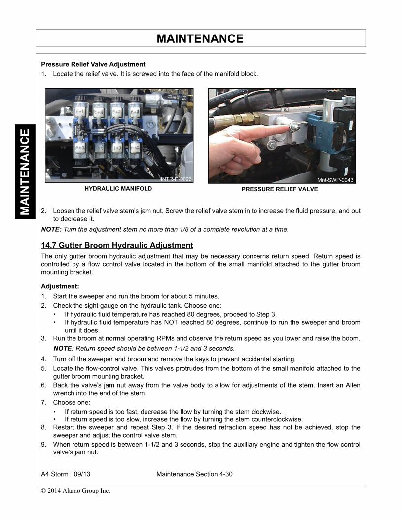
MAINTENANCEM
AIN
TE
NA
NC
E
Pressure Relief Valve Adjustment
1. Locate the relief valve. It is screwed into the face of the manifold block.
2. Loosen the relief valve stem’s jam nut. Screw the relief valve stem in to increase the fluid pressure, and outto decrease it.
NOTE: Turn the adjustment stem no more than 1/8 of a complete revolution at a time.
14.7 Gutter Broom Hydraulic AdjustmentThe only gutter broom hydraulic adjustment that may be necessary concerns return speed. Return speed iscontrolled by a flow control valve located in the bottom of the small manifold attached to the gutter broommounting bracket.
Adjustment:
1. Start the sweeper and run the broom for about 5 minutes.
2. Check the sight gauge on the hydraulic tank. Choose one:
• If hydraulic fluid temperature has reached 80 degrees, proceed to Step 3.• If hydraulic fluid temperature has NOT reached 80 degrees, continue to run the sweeper and broom
until it does.3. Run the broom at normal operating RPMs and observe the return speed as you lower and raise the boom.
NOTE: Return speed should be between 1-1/2 and 3 seconds.
4. Turn off the sweeper and broom and remove the keys to prevent accidental starting.
5. Locate the flow-control valve. This valves protrudes from the bottom of the small manifold attached to thegutter broom mounting bracket.
6. Back the valve’s jam nut away from the valve body to allow for adjustments of the stem. Insert an Allenwrench into the end of the stem.
7. Choose one:
• If return speed is too fast, decrease the flow by turning the stem clockwise.• If return speed is too slow, increase the flow by turning the stem counterclockwise.
8. Restart the sweeper and repeat Step 3. If the desired retraction speed has not be achieved, stop thesweeper and adjust the control valve stem.
9. When return speed is between 1-1/2 and 3 seconds, stop the auxiliary engine and tighten the flow controlvalve’s jam nut.
HYDRAULIC MANIFOLD PRESSURE RELIEF VALVE
A4 Storm 09/13 Maintenance Section 4-30
© 2014 Alamo Group Inc.

MAINTENANCEM
AIN
TE
NA
NC
E
15. DUST SUPPRESSION SYSTEM MAINTENANCE
For dust suppression during sweeping operations, water flows from the two 65-gallon reservoirs and throughthe ‘Y’ strainer and the hydraulically-driven water pump. Then, it goes through the water manifold and hoses tothe spray nozzles.
Depending upon where dust suppression is needed, water may be directed from the sweeper console to any orall of the following:
• The nozzles in the front spray bar• Gutter broom dual-body spray nozzles• Hopper nozzles on the intake tube• Nozzles placed at the four corners of the head
Water being drawn from the water reservoir to the water pump passes through the Y strainer screen, trappingand preventing debris from reaching the rest of the dust suppression system. Because the Y strainer trapsdebris that could clog spray nozzles, it must be cleaned daily.
We recommend the maintenance listed in the following table:
15.1 Water Reservoir RefillTo refill the water reservoir, use the 25-foot hose, stowed in the tool box on the sweeper.
Replacement:
1. Turn on the hydrant and allow the water to run for a short interval so any rust and/or sediment trapped inthe water line can be cleared.
An uncleared water line can introduce debris to the sweeper’s water system, necessitatingfurther cleaning and exposing the sweeper to possible damage.
2. Remove the 2-1/2” hydrant hose from its storage rack beneath the right side of the water reservoir tray andattach its end to the hydrant. The opposing hose end is attached to the pipe feeding the air-gapped fillopening of the reservoir.
3. Allow the reservoir to fill until water gushes from its overflow.
Maintenance Frequency Section/Title Reference
Clean the ‘Y’ Strainer. Daily ‘Y’ Strainer Cleaning, ‘Y’ Strainer Replacement
Inspect and clean the nozzle.s Daily Water Nozzle Cleaning Replacement
Winterize the system. As needed Dust Suppression System Winterizing
A4 Storm 09/13 Maintenance Section 4-31
© 2014 Alamo Group Inc.
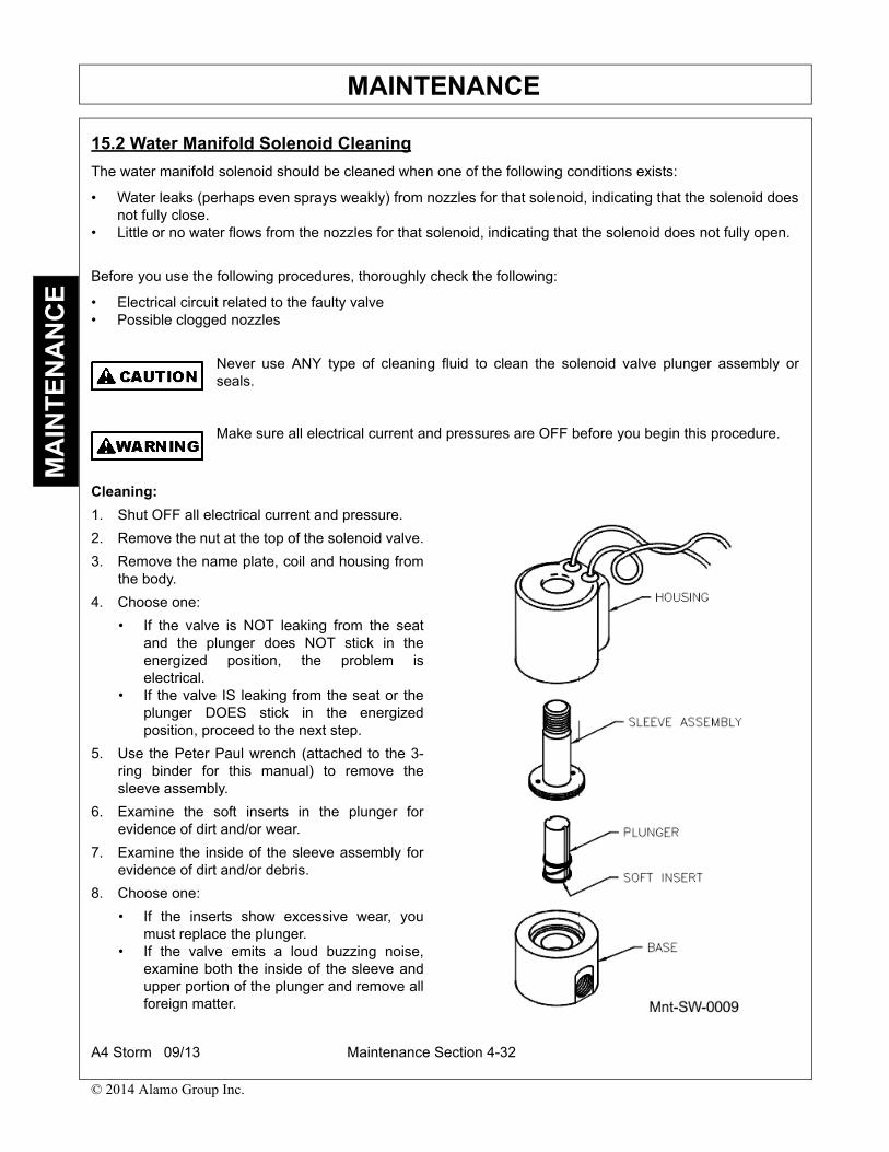
MAINTENANCEM
AIN
TE
NA
NC
E
15.2 Water Manifold Solenoid Cleaning
The water manifold solenoid should be cleaned when one of the following conditions exists:
• Water leaks (perhaps even sprays weakly) from nozzles for that solenoid, indicating that the solenoid doesnot fully close.
• Little or no water flows from the nozzles for that solenoid, indicating that the solenoid does not fully open.
Before you use the following procedures, thoroughly check the following:
• Electrical circuit related to the faulty valve• Possible clogged nozzles
Never use ANY type of cleaning fluid to clean the solenoid valve plunger assembly orseals.
Make sure all electrical current and pressures are OFF before you begin this procedure.
Cleaning:
1. Shut OFF all electrical current and pressure.
2. Remove the nut at the top of the solenoid valve.
3. Remove the name plate, coil and housing fromthe body.
4. Choose one:
• If the valve is NOT leaking from the seatand the plunger does NOT stick in theenergized position, the problem iselectrical.
• If the valve IS leaking from the seat or theplunger DOES stick in the energizedposition, proceed to the next step.
5. Use the Peter Paul wrench (attached to the 3-ring binder for this manual) to remove thesleeve assembly.
6. Examine the soft inserts in the plunger forevidence of dirt and/or wear.
7. Examine the inside of the sleeve assembly forevidence of dirt and/or debris.
8. Choose one:
• If the inserts show excessive wear, youmust replace the plunger.
• If the valve emits a loud buzzing noise,examine both the inside of the sleeve andupper portion of the plunger and remove allforeign matter.
A4 Storm 09/13 Maintenance Section 4-32
© 2014 Alamo Group Inc.

MAINTENANCEM
AIN
TE
NA
NC
E
Be very careful not to damage the sleeve seat or plunger face. If you mar either surface,you must replace the entire sleeve and plunder assembly.
If you must remove the entire valve assembly from the line, be very careful that no foreignmatter gets into the valve. During reconnection, pipe-thread chips in either the seat or thesoft inserts will cause valve malfunction.
Order replacement parts bearing the valve number, voltage, and frequency specified on thename plate.
9. After cleaning or replacing parts, verify that both the flange seal and the return spring are in place.
10. Loosely screw the sleeve assembly into the body.
Do NOT connect the valve to the electrical circuit.
11. Before you tighten the sleeve assembly to the body, choose one:
• If the valve has a sleeve port, cap the port and apply pressure to the port leading to the body chamber.• If the media is air or gas, apply water to the joint and watch for air bubbles.
12. Reattach the name plate, coil, and housing to the body.
13. Carefully tighten the nut at the top of the solenoid valve.
Excessive tightening of the nut can cause unnecessary strain on either the sleeveassembly or the coil under the housing.
14. Restart electrical current and pressure.
15.3 ‘Y’ Strainer Cleaning/ReplacementThe dust suppression system ‘Y’ strainer should be replaced when you notice damage during strainer cleaning.
Cleaning/Replacement:
NOTE: Cleaning the ‘Y’ strainer requires opening the ‘Y’ strainer housing. This procedure should be done atthe end of the work shift when the reservoir’s water level will be at its lowest.
1. Unscrew the bottom of the ‘Y’ strainer.
2. After the water flow stops, remove the screen from inside the ‘Y’ strainer housing and examine.
3. Choose one:
• Remove any debris inside the ‘Y’ strainer and rinse the cylindrical screen.• If the strainer is damaged, replace it.
4. Slip the screen back into position
5. Reassemble the ‘Y’ strainer housing.
15.4 Water Pump MaintenanceThe water pump is a 5-stage diaphragm with a 3.4 (GPM) output at 50 PSI. Because the pump is mountedbelow the reservoir, it does not need priming.
The only maintenance required is a monthly check of the water pump pressure to ensure proper dustsuppression and water pump life.
Turn OFF the auxiliary engine before you work on the water pump.
A4 Storm 09/13 Maintenance Section 4-33
© 2014 Alamo Group Inc.

MAINTENANCEM
AIN
TE
NA
NC
E
15.5 Water Pump Pressure Check
Pressure Verification:
1. Use a gauge to check the pump’s output pressure.
2. Open the boiler drain.
3. Turn the console control panel switch, which operates the water pump, to the ON position.
4. Be sure all the console control panel switches operating the sweeper’s water functions are in the OFFposition.
5. Read the gauge and choose one:
• If the gauge reads roughly 50 PSI, no adjustment is needed.• If the pressure gauge reading is considerably different from 50 PSI, you may need to adjust the water
pump’s relief valve. Pressure that is jet too high can cause premature water pump failure.
6. Locate the relief valve adjustment on the front of the water pump.
7. Turn the hexed stem of the relief valve to adjust the water system pressure.
8. When the water pressure is roughly 50 PSI, pressure has been set.
15.6 Water Nozzle Cleaning/ReplacementA dust suppression system nozzle needs cleaning when it is clogged and water flow is restricted.
Due to dusty conditions encountered during sweeping operations, dirt and debris particles entering the dustsuppression system are sometimes small enough to pass through the ‘Y’ strainer. These particles can build upwithin a nozzle’s openings, restricting water flow. When this occurs, the nozzle must be cleaned or replaced.
Cleaning/Replacement:
1. Unscrew the nozzle retainer cap and set itaside.
2. Remove the spray tip and strainer.
3. Wash the strainer and examine it.
4. Choose one:
• If washing the strainer has removed all particlesor debris, set aside the (now clean) strainer.
• If the strainer can no longer be thoroughlycleaned, it needs to be replaced.
5. Wash the spray tip and examine it.
6. Choose one:
• If the spray-tip opening is clogged, insert asmall-gauge wire into the spray-tip openingto clear any debris lodged inside.
• If the spray tip is damaged, it needs to bereplaced.
7. Reassemble the nozzle, replacing anydamaged parts as necessary.
8. Unscrew the bottom of the ‘Y’ strainer housingto drain the water reservoir(s).
9. After the water flow stops, reassemble the ‘Y’strainer housing.
WATER NOZZLEDISASSEMLBY
A4 Storm 09/13 Maintenance Section 4-34
© 2014 Alamo Group Inc.

MAINTENANCEM
AIN
TE
NA
NC
E
15.7 Dust Suppression System Winterizing
You must winterize whether or not you will use your sweeper during freezing temperatures. In either case,winterizing your Schwarze A4 Sweeper will help keep it in top operating condition, extending its length ofservice.
Failure to winterize the dust suppression system could result in damage to your sweeper.
Choose one:
• If your sweeper’s dust suppression system will be operated during freezing temperatures, complete thefirst procedure.
• If your sweeper’s dust suppression system will NOT be operated for several weeks when freezingtemperatures are expected, complete the second procedure.
System Winterization:
If antifreeze is to be used to protect the sweeper’s water system, it is imperative that it bean environmentally safe antifreeze. Common non-biodegradable antifreeze should NEVERbe used in the water system.
1. Following the antifreeze manufacturer’s instructions, add environmentally safe antifreeze to the water bypouring it through the air-gap opening in the top of the reservoir.
2. Turn Auxiliary Engine key switch to the ‘ON’ position. (Starting the engine is not required.)
3. Turn ON the Water pump.
4. Turn ON all cab console control panel switches controlling water manifold solenoids.
5. Leave switches ON until the antifreeze/water mixture flows from the spray nozzles.
6. Turn OFF all cab console control panel switches controlling water manifold solenoids.
7. Turn the auxiliary engine key switch OFF.
System Draining:
1. Unscrew the bottom of the ‘Y’ strainer housing to drain the water reservoir(s).
2. After the water flow stops, reassemble the ‘Y’ strainer housing.
3. Turn ON all cab console control panel switches controlling water manifold solenoids.
4. Connect high-pressure air to the air valve stem located near the water pump.
5. When lines have emptied, turn OFF all console control panel switches controlling water manifoldsolenoids.
6. Open the cock drain on the bottom of the water manifold.
A4 Storm 09/13 Maintenance Section 4-35
© 2014 Alamo Group Inc.


A4 Storm 09/13 Version 1.0 09/13Printed U.S.A
A4 STORMSWEEPER