a3 super ii - hobbyeagle · [email protected] 6 connection a3 super supports a standard...
TRANSCRIPT
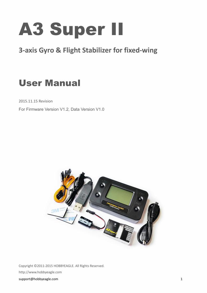
A3 Super II 3-axis Gyro & Flight Stabilizer for fixed-wing
User Manual
2015.11.15 Revision
For Firmware Version V1.2, Data Version V1.0
Copyright ©2011-2015 HOBBYEAGLE. All Rights Reserved.
http://www.hobbyeagle.com

Package Contents
Main Controller × 1
The main controller has a built-in 32-bit MCU and a MEMs sensor consist of a
3-axis gyroscope and a 3-axis accelerometer. There are up to 7 input channels and
5 output channels. It also has a 4-pin data interface for connecting the program
card and PC. A RGB LED is used to display the operation state. The main controller
is small in size and light in weight, it can be attached flat or upright, and even
upside down under the plane.
Program Card × 1 (Optional)
The program card is used to setup the controller more quickly
and easily, especially in the field. The card has a white backlit
LCD screen and supports both Chinese and English languages.
The firmware of the card can be upgraded online and it can be
also used for other products from HOBBYEAGLE.
Receiver Cable × 3
Cables used to connect the main controller and the receiver. Including male to male
power lead 15cm × 1, combined signal lead 15cm × 2.
USB Adapter × 1
This adapter is used to connect to PC.
3M Double-sided Tapes × 2
The double-sided tapes are used to attach the controller on the fuselage.
Voltage Protector × 1
This capacitor is used to secure working voltage level for the controller and only used when
needed.
Package Contents .......................................................................................................................................... 2
Installation .................................................................................................................................................... 5
Connection .................................................................................................................................................... 6
Standard Receiver .......................................................................................................................................... 6
Futaba S.Bus / S.Bus 2 .................................................................................................................................... 6
Flight Modes ................................................................................................................................................. 8
Gyro Off Mode ............................................................................................................................................... 8
Normal Mode ................................................................................................................................................ 8
3D AVCS Mode............................................................................................................................................... 8
Auto-balance Mode ....................................................................................................................................... 8
Auto-hover Mode .......................................................................................................................................... 8
User Defined Mode ........................................................................................................................................ 8
Stick Control Modes ...................................................................................................................................... 9
Manual Mode (MM) ...................................................................................................................................... 9
Auto Mode (RR/AR) ....................................................................................................................................... 9
Wing Type ....................................................................................................................................................10
LED Descriptions ..........................................................................................................................................11
Gyro Direction ..............................................................................................................................................11
Confirm the gyro direction on Aileron ...........................................................................................................12
Confirm the gyro direction on Elevator .........................................................................................................12
Confirm the gyro direction on Rudder ...........................................................................................................12
Quick Start ...................................................................................................................................................13
Config Software............................................................................................................................................14
Software and USB Driver Installation ............................................................................................................14
GUI ...............................................................................................................................................................14
Main Menu ...................................................................................................................................................15
Language ......................................................................................................................................................15
Connection Wizard .......................................................................................................................................16
Read .............................................................................................................................................................17

Write ............................................................................................................................................................17
Firmware Update ..........................................................................................................................................17
Basic Settings ................................................................................................................................................19
Wing Type ....................................................................................................................................................20
Mounting ......................................................................................................................................................20
Gain ..............................................................................................................................................................20
Radio ............................................................................................................................................................21
Level Offset ..................................................................................................................................................22
Hover Offset .................................................................................................................................................23
Debug Mode .................................................................................................................................................23
Program Card ...............................................................................................................................................24
Buttons .........................................................................................................................................................24
Connection ...................................................................................................................................................24
Language ......................................................................................................................................................25
Menu Operation ...........................................................................................................................................25
Option Selection ...........................................................................................................................................25
Value Modification .......................................................................................................................................25
*Voltage Protector .......................................................................................................................................26
Specifications ...............................................................................................................................................26
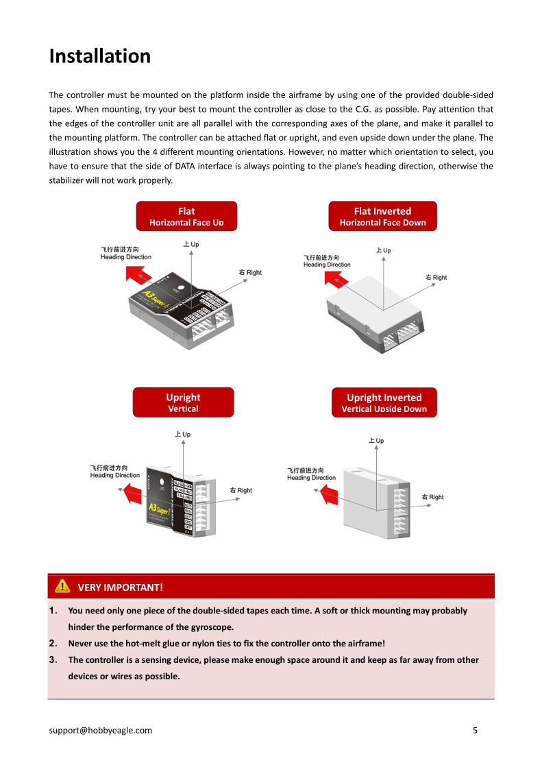
Installation
The controller must be mounted on the platform inside the airframe by using one of the provided double-sided tapes. When mounting, try your best to mount the controller as close to the C.G. as possible. Pay attention that the edges of the controller unit are all parallel with the corresponding axes of the plane, and make it parallel to the mounting platform. The controller can be attached flat or upright, and even upside down under the plane. The illustration shows you the 4 different mounting orientations. However, no matter which orientation to select, you have to ensure that the side of DATA interface is always pointing to the plane’s heading direction, otherwise the stabilizer will not work properly.
VERY IMPORTANT!
1. You need only one piece of the double-sided tapes each time. A soft or thick mounting may probably
hinder the performance of the gyroscope.
2. Never use the hot-melt glue or nylon ties to fix the controller onto the airframe!
3. The controller is a sensing device, please make enough space around it and keep as far away from other
devices or wires as possible.
Flat Horizontal Face Up
Flat Inverted Horizontal Face Down
Upright Vertical
Upright Inverted Vertical Upside Down

Connection
A3 Super supports a standard receiver or a Futaba’s S.Bus receiver. You don’t need to connect all of the 7 input
channels, just connect those you want to use. The controller will detect the input signal for each channel and
enable or disable the correlation functions automatically. For example, if the input [AIL2] is connected, the dual
aileron control system will be activated by the controller. It’s recommended that you should at least connect the
channels for [AIL], [ELE], [RUD] and [MOD].
Standard Receiver
Futaba S.Bus / S.Bus 2
When using a Futaba’s S.Bus receiver, you can make a single-line connection between the receiver and the
controller. Just plug the male to male lead into the input [S.Bus/MOD] and from the receiver’s s.bus output pin. In
this case, you don’t need to connect other inputs of the controller anymore. As the S.Bus is a single-line solution
all channels are transmitted via one single line, in order to make the controller distinguish the input signals for
each channel correctly, you have to tell it the channel mapping on your transmitter by using the program card or
the config software. A3 Super supports a maximum of 16 channels when using S.Bus solution.

VERY IMPORTANT!
1. Please respect the polarities for the plugs going to the controller. The orange signal line must always be on
the top and the brown on the bottom.
2. Check all the connectors and make sure that all of them are firmly connected to the pins.
3. If both [AIL] and [AIL2] are connected, the dual aileron control function will be activated. The [OUT1] and
[OUT4] are used to connect the 2 aileron servos. If the input [AIL2] is not connected, the controller will
switch to single aileron input mode. In this case, you can still plug the 2 aileron servos into [OUT1] and
[OUT4], just as using a Y-cable on the aileron. It’s quite the same as when using the dual elevator.
4. Please refer to the manual of your radio to find the right way to assign a 3-position switch for flight mode
control, and a knob or slide lever for remote master gain control.
5. You have to reboot the controller after you change the receiver type to make the new setting take effect.
Port Description
Inputs
AIL For aileron control
ELE For elevator control
RUD For rudder control
AIL2 For aileron 2 control
ELE2 For elevator 2 control
GAIN For remote master gain control
S.Bus/MOD For flight mode switch or Futaba’s S.Bus input. It’s also the power supply interface of the
controller.
Outputs
OUT1 To aileron servo
OUT2 To elevator servo
OUT3 To rudder servo
OUT4 To the second aileron servo
OUT5 To the second elevator servo
Others
DATA To the program card and the PC
Flight Modes
A3 Super provides 6 different flight modes.
Gyro Off Mode
Choose this mode to disable the gyros for all channels. The plane will be completely under the control of the radio.
The plane will go back to its previous performance when operating it in this mode. Usually it is only used to test.
Normal Mode
Normal mode is the most basic application of the gyro. In this mode, the gyro will sense angular velocity on each
axis and make a momentary reaction. The normal mode is suitable for all types of fixed-wings, it can effectively
improve the stability of your plane specially on a windy day.
3D AVCS Mode
The AVCS mode is an advanced application of the gyro. By adding an integral algorithm to the gyros, the controller
will try to lock the plane to its previous attitude if there is no command sent from the transmitter in a flight. This
mode can effectively help you to accomplish such hard actions as hover and knife edge. But this mode is designed
especially for the 3D planes, it’s not suitable for the planes those not designed for 3D flight.
Auto-balance Mode
The auto-balance mode is designed for the new beginners or the FPV applications. When operating in this mode,
the controller will command the plane to maintain level flight automatically when you release the sticks. When
switch it to this mode from any other modes in an emergency, the plane will recover to the level flight
automatically, which we call “one-click rescue”.
Auto-hover Mode
The auto-hover mode is another form of the self balance ability of the controller. The only difference is that the
correction from the gyro will be applied to both pitch and yaw axes, to keep the plane always vertical. When
switch to this mode, the plane will lift its nose and start to hover automatically, which we call “one-click hover”.
User Defined Mode
This mode allows you to select different mode for each axis, from normal , 3D or gyro off mode.

Stick Control Modes
A3 Super provides 2 different control modes for the sticks, including Manual Mode and Automatic Mode. The
default is Manual Mode when you first get it.
Manual Mode (MM)
When manual mode is chosen, the sticks are used to control the surfaces directly as usual. That is, there is no
rotation rate or tilt angle locking and limitation when you move the sticks. All the servos will be completely under
the control of the radio. It’s more obvious to the users because you can see the servos move following the sticks as
you expected. The plane will maintain its original control behavior when operating it in this mode.
Auto Mode (RR/AR)
When using this mode, the controller will take over the control of all servos. The sticks are used to control the
rotation rate (RR) on each axis when flying in normal or 3D mode, or the tilt angle rate (AR) on each axis when
flying in auto-balance or auto-hover mode. The max rotation rate and max tilt angle can be set in the program
card or the config software. In this mode, the controller will handle the position of the surfaces based on the
actual rotation rate or tilt angle of the plane intelligently. This is why the movement of the servo will become
different from the manual mode.
Flight Mode Stick Control Mode
Manual Mode Auto Mode
Gyro Off Mode MM MM
Normal Mode MM RR
3D AVCS Mode MM RR
Auto-balance Mode MM AR
Auto-hover Mode MM AR
User Defined Mode Depends on the flight mode of each axis
MM: Stick controls the servo directly.
RR: Stick controls the rotation rate on each axis.
AR: Stick controls the tilt angle rate on each axis.
* Whatever the setting of control mode is, the stick is always used to control the servo directly when operating in gyro off mode or the gyro of the corresponding axis has been disabled.
When operating in Auto Mode, the range of movement of the servos will become larger than before
when moving the sticks, this is normal because a rotation rate or tilt angle set point has been applied
to the outputs by the gyro.

Wing Type
A3 Super supports a standard wing type of the fixed-wing, including 1AIL+1ELE, 1AIL+2ELE, 2AIL+1ELE, 2AIL+2ELE,
and a delta-wing or V-tail mixing. Connect the servos following the illustration below.

NEVER use the delta-wing and V-tail mixing functions on your transmitter, all you need is to choose
a single 4-channel fixed-wing model type on your radio at any time.
LED Descriptions
Flight Mode
Solid Red Gyro off Mode, or the gyros has been disabled on all channels
Solid Blue Normal Mode
Solid Violet 3D AVCS Mode
Solid White Auto-balance Mode
Solid Green Auto-hover Mode
Solid Yellow User Defined Mode
Power On
White, 2 seconds Ready to start initialization, don’t move the plane!
White, Fast Flashing, 2 seconds Power-on gyro calibration, don’t move the plane!
Red, Fast Flashing Initialization failed, please reboot the controller.
Operating
White, Fast Flashing, 1 sec Stick centering
… … … Green, Flashing, 6 seconds Auto level calibrating or auto hover calibrating
…… …… Red, Slow Flashing No signal input, you must get AIL, ELE and RUD connected
Red, Rapid Flashing Sensor failure, please contact us.
Gyro Direction
It’s extremely important to make sure that the gyro reacts in the correct direction on all axes before
flight, otherwise it could lead to losing control or even crash after takeoff!

Confirm the gyro direction on Aileron
Quickly move the right wing downward around the roll axis, the right aileron surface should flap down and the left flap up as shown below.
Confirm the gyro direction on Elevator
Quickly move the nose of the plane downward around the pitch axis, the elevator surface should flap up as shown below.
Confirm the gyro direction on Rudder
Quickly move the nose of the plane to the left around the yaw axis, the rudder surface should flap right as shown below.
Quick Start
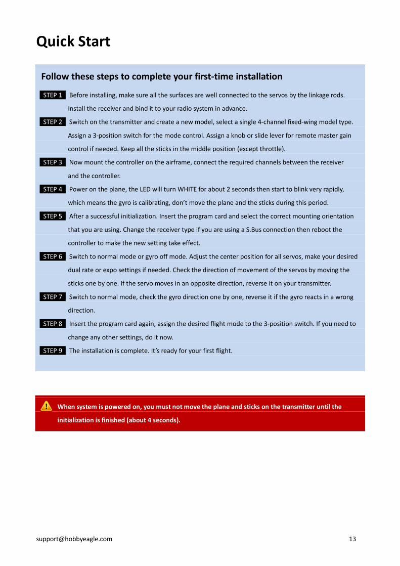
Follow these steps to complete your first-time installation
STEP 1 Before installing, make sure all the surfaces are well connected to the servos by the linkage rods.
Install the receiver and bind it to your radio system in advance.
STEP 2 Switch on the transmitter and create a new model, select a single 4-channel fixed-wing model type.
Assign a 3-position switch for the mode control. Assign a knob or slide lever for remote master gain
control if needed. Keep all the sticks in the middle position (except throttle).
STEP 3 Now mount the controller on the airframe, connect the required channels between the receiver
and the controller.
STEP 4 Power on the plane, the LED will turn WHITE for about 2 seconds then start to blink very rapidly,
which means the gyro is calibrating, don’t move the plane and the sticks during this period.
STEP 5 After a successful initialization. Insert the program card and select the correct mounting orientation
that you are using. Change the receiver type if you are using a S.Bus connection then reboot the
controller to make the new setting take effect.
STEP 6 Switch to normal mode or gyro off mode. Adjust the center position for all servos, make your desired
dual rate or expo settings if needed. Check the direction of movement of the servos by moving the
sticks one by one. If the servo moves in an opposite direction, reverse it on your transmitter.
STEP 7 Switch to normal mode, check the gyro direction one by one, reverse it if the gyro reacts in a wrong
direction.
STEP 8 Insert the program card again, assign the desired flight mode to the 3-position switch. If you need to
change any other settings, do it now.
STEP 9 The installation is complete. It’s ready for your first flight.
When system is powered on, you must not move the plane and sticks on the transmitter until the
initialization is finished (about 4 seconds).

Config Software
Software and USB Driver Installation
Please download the USB driver and the config software from our website
www.hobbyeagle.com. Run the setup.exe and follow the instructions to complete installation.
After setup, you will then get an icon on your desktop, as shown to the right.
VERY IMPORTANT!
1. The software only supports Win XP, Win 7 and Win 8.
2. If you are using Win XP, you have to install the Microsoft .NET Framework 2.0 before installing the software.
The framework can be downloaded from our website or the Microsoft’s website.
GUI

Main Menu
Click the icon on the title bar to open the main menu. The main menu contains all functions.
Menu Description
简体中文/English Select language between English and Chinese.
Select Port Open the connection wizard.
Read Read settings from the controller.
Write Write settings into the controller.
Open Config File Load settings from a file.
Save Config As Save current settings to a file.
Restore Factory Settings Reset the controller to the default settings.
Firmware Update Open the firmware update wizard.
About View the version and copyright informations.
Language
You can select the language from the main menu. You need to restart the software after change the language.

Connection Wizard
STEP 1 Click “Select Port” from the main menu to open the Connection Wizard.
STEP 2 Plug in the USB adapter to the USB port on your PC, make sure you have installed the USB driver.
STEP 3 Click “Next”, the available ports will appear in the list, just select the correct one.
STEP 4 Click “OK” to back to the main form, now you can find the status of the port displayed on the left of the
status bar.
1 2
3

Read
After selecting the port, connect the controller to the USB adapter and wait until the initialization is done. Click
“Read” to read the settings to the software from the controller. After a successful reading, you can see the current
firmware version and data version of the controller in the lower-right corner of the form.
VERY IMPORTANT!
1. If you are going to connect the controller to the PC while the plane is power off, please disconnect all of the
servos to prevent the fact that the USB port or the controller is demolished by an excessive current.
2. Please wait until the initialization is finished before you operating the software.
3. The firmware version number of the program card and the config software are corresponding to the Data
Version that the controller is using. That means you don’t need to upgrade the program card or the
software if the data version number doesn’t change even if you have upgraded the firmware of the
controller.
Write
After making your change of the settings, click “Write” to save the modified settings into the controller. The new
settings will take effect immediately.
Firmware Update
VERY IMPORTANT!
1. Disconnect all of the servos from the controller and power off the plane before starting update. It is very
important to confirm that you have disconnected the power at the beginning, otherwise the update
procedure won’t work in the next steps.
2. Both the controller and the program card can be upgraded online using the update wizard.
3. The update wizard needs to get the available firmware list from the server, please make sure your computer
is connected to the internet.
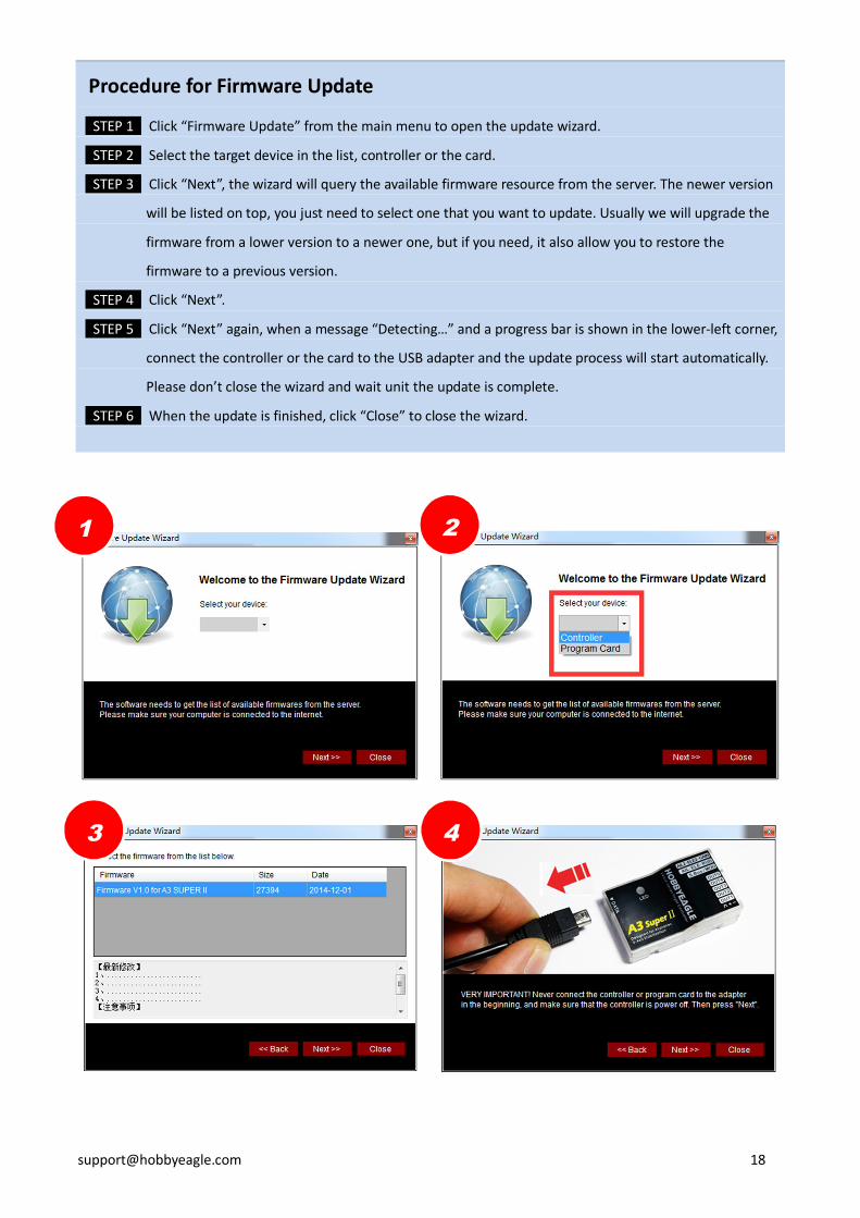
Procedure for Firmware Update
STEP 1 Click “Firmware Update” from the main menu to open the update wizard.
STEP 2 Select the target device in the list, controller or the card.
STEP 3 Click “Next”, the wizard will query the available firmware resource from the server. The newer version
will be listed on top, you just need to select one that you want to update. Usually we will upgrade the
firmware from a lower version to a newer one, but if you need, it also allow you to restore the
firmware to a previous version.
STEP 4 Click “Next”.
STEP 5 Click “Next” again, when a message “Detecting…” and a progress bar is shown in the lower-left corner,
connect the controller or the card to the USB adapter and the update process will start automatically.
Please don’t close the wizard and wait unit the update is complete.
STEP 6 When the update is finished, click “Close” to close the wizard.
1 2
3 4

Basic Settings
Flight Mode By using a 3-position switch, you can change the flight mode in flight, here you can assign your
desired flight mode for each position of the switch. If the input [MOD] is not connected, system will always
default to the mode that has been assigned to Position-1.
User Mode Select different flight mode separately for aileron, elevator and rudder.
Response Rate A3 Super uses a high sensitivity and high precision MEMs sensor, you need to try your best to
reduce the influence caused by vibration during installation. This option give you another way to filter the noise by
software. The default setting is Normal, usually it will be suitable for most planes. However, if you have made
effective measures to reduce the vibration, you can try a faster response rate setting to get a better performance.
On the contrary, you should use a slower rate when the controller is working in a high vibration situation.
Servo Frequency It’s used to select the working frequency for the servos. To optimize the performance of the
controller, the rule is the higher the better! But please note that analog servos usually tolerate only 50Hz. Digital
servos usually allow higher frequencies, but this has to be verified in the manual of your servos. If you don’t know
what the maximum frequency tolerated by your servos is, please leave this option to its default setting.
A higher working frequency can lead to failure of your servos!
Travel Limit This function is used to limit the maximum travel range for the servos. The max limit is determined
by the maximum possible control travel of the mechanism. The limits can be adjusted from 0 to 100%, the default
setting is 100%, corresponding to a pulse width from 1020uS to 2020uS. After setting a limit, the range of
movement of the servos will be limited within the safety range. The setting for aileron channel will be applied to
OUT1 and OUT4. The setting for elevator channel will be applied to OUT2 and OUT5. The setting for rudder will be
applied to OUT3.
Gyros Here you can reverse the gyro or turn off the gyro separately for each channel.
5 6
Wing Type
Select your wing type, see Page 10.
Mounting
Select the mouting orientation of the controller, see Page 5.
Gain
This tab is used to setup the gain for each flight mode. The gain is affected by many factors there is no standard
answer to that how much it should be. You need to fine-tune to get the best result. The plane will be oscillating in
the corresponding direction if the gain is set too high, this is a result of over amplification of the gyros, this rapid
back and forth movement can make the plane hard to control. But if the gain is too low, the plane will likely to be
hard to control. We suggest you start your first flight with a lower gain setting and then increase them gradually.
You can also use the remote master gain channel to get a more convenient way to adjust the gain when in a flight.
Gain Rate In order to meet more needs, A3 Super provides 3-level (Small, Medium and Large) gain level for
each flight mode. You can choose a larger level when the current gain is still not large enough, even when it has
been set to the maximum. However it is recommended to use as small level as possible to improve the precision
of gain adjustment.
VERY IMPORTANT!
1. A3 Super is aimed at all types of fixed-wing airplanes. Usually the default gain settings are ready to go.
However, sometimes you still have to adjust the settings manually according to your plane to get the best
flying experience.
2. To get the best performance in auto-hover mode, try to use the maximum gain for auto-hover mode.
3. The Auto-balance or Auto-hover gain will be affected by the Normal Gain. Before adjusting the balance or
hover gain, you need to get the appropriate normal gain setting first.

Radio
All parameters related to the radio system can be setup within this tab.
Control Mode Choose the stick control mode, see Page 9.
Receiver Type Choose the receiver type, remember to reboot the controller after change the type.
Rotation Rate Choose the max rotation rate of the plane. This setting will only take effect when the stick
control mode is set to Auto Mode. Also see Page 9 for more details about stick control mode.
Max Tilt Angle Choose the max tilt angle of the plane. The setting will only take effect when the stick control
model is set to Auto Mode. Also see Page 9 for more details about stick control mode.
Stick Deadband The dead band is the range around the very center of the sticks at where the controller will not
react. Some transmitters have the problem that when the sticks are brought back after an input, they are not
exactly at the same center position as before which may generate a deviation on the corresponding function,
although the sticks seems to be in the middle. This parameter can be adjusted between 0% and 10%, the default
setting is 5%. You can set it higher if it is difficult to find the stick center position even the stick centering function
has been applied already. The dead band setting is for all channels.
S..Bus Channels When you are using a S.Bus connection, you need to tell the controller that which channel is
using for aileron, or elevator and so on. The controller should be told with the channel mapping before it can work
properly. For example, if you are using channel 5 for the flight mode switch function, you have to select CH5 to the
input [MOD]. If you are using channel 6 for the second aileron, you have to select CH6 to the input [AIL2]. Select
“None” to tell the controller that you don’t want to use this channel.
Stick Centering Stick centering is used to calibrate and re-learn the new center position of the sticks. Usually, in
the first flight, you need to make a little trim to make the plane flying properly. Once the trims are set on your
transmitter. You need to land the plane and perform a stick centering so the controller can re-learn the new
adjustments that were just made. The stick centering is only for channels of aileron, elevator, rudder, aileron2 and
elevator2, the mode and gain channels will be ignored when calibrating. And for those channels unconnected, the
controller will skip them automatically. Stick centering needs only 1 second, while calibrating, the LED will blink
WHITE rapidly.
Power-on Automatic Stick Centering A3 Super will perform a stick centering automatically every time it starts, so you can change the trims anytime you
need, the new center positions will be re-learned and saved in the next time it starts. Remember to keep all sticks
(except throttle) in their middle position before power on the controller, and don’t move them during
initialization.
Perform a centering by toggling the switch To prevent misoperation in the flight, this function has been cancelled in F/W V1.2. Restart the controller to
make the new center positions learned and saved if you change the trimming settings.
VERY IMPORTANT!
1. If the servos drift to one side slowly when switching to 3D mode, you have to perform a stick centering.
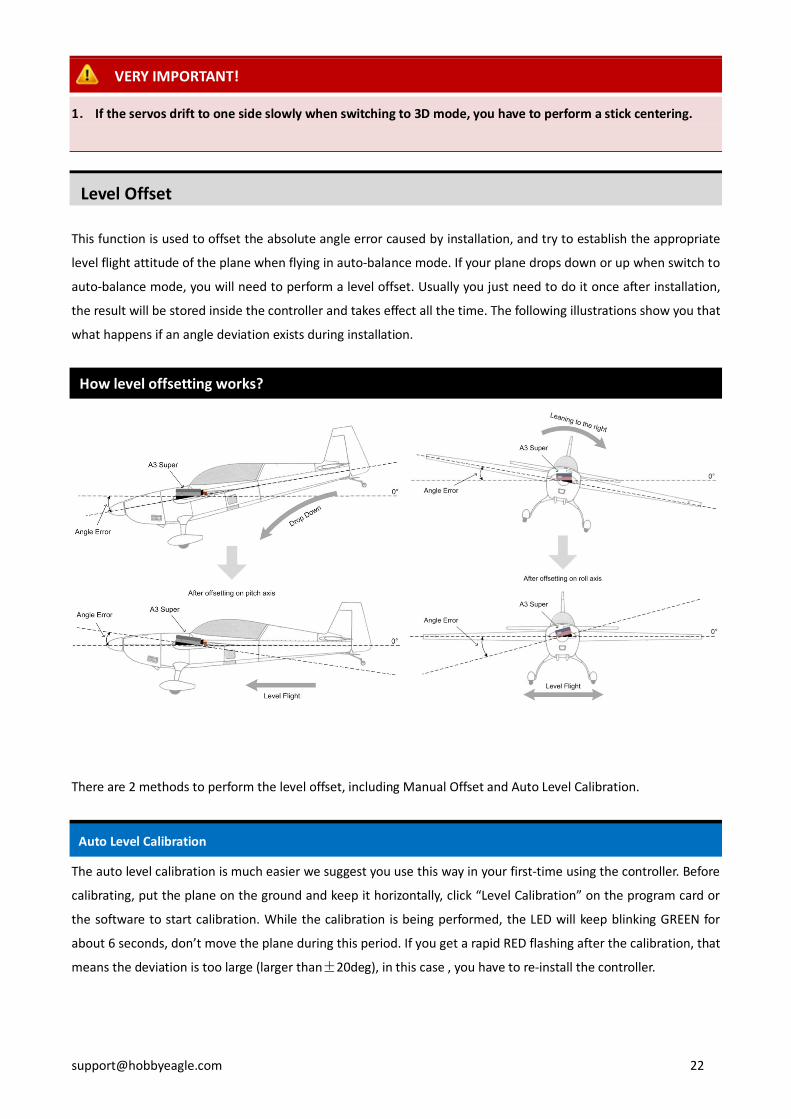
Level Offset
This function is used to offset the absolute angle error caused by installation, and try to establish the appropriate
level flight attitude of the plane when flying in auto-balance mode. If your plane drops down or up when switch to
auto-balance mode, you will need to perform a level offset. Usually you just need to do it once after installation,
the result will be stored inside the controller and takes effect all the time. The following illustrations show you that
what happens if an angle deviation exists during installation.
How level offsetting works?
There are 2 methods to perform the level offset, including Manual Offset and Auto Level Calibration.
Auto Level Calibration
The auto level calibration is much easier we suggest you use this way in your first-time using the controller. Before
calibrating, put the plane on the ground and keep it horizontally, click “Level Calibration” on the program card or
the software to start calibration. While the calibration is being performed, the LED will keep blinking GREEN for
about 6 seconds, don’t move the plane during this period. If you get a rapid RED flashing after the calibration, that
means the deviation is too large (larger than±20deg), in this case , you have to re-install the controller.
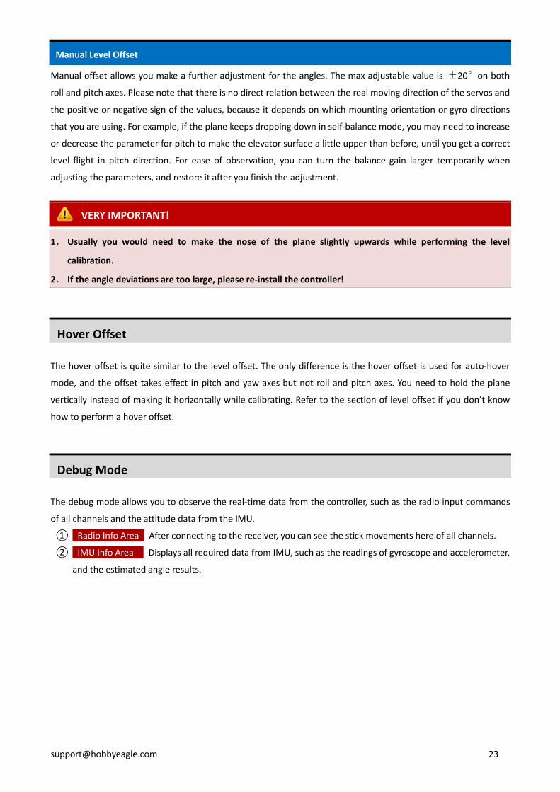
Manual Level Offset
Manual offset allows you make a further adjustment for the angles. The max adjustable value is ±20°on both
roll and pitch axes. Please note that there is no direct relation between the real moving direction of the servos and
the positive or negative sign of the values, because it depends on which mounting orientation or gyro directions
that you are using. For example, if the plane keeps dropping down in self-balance mode, you may need to increase
or decrease the parameter for pitch to make the elevator surface a little upper than before, until you get a correct
level flight in pitch direction. For ease of observation, you can turn the balance gain larger temporarily when
adjusting the parameters, and restore it after you finish the adjustment.
VERY IMPORTANT!
1. Usually you would need to make the nose of the plane slightly upwards while performing the level
calibration.
2. If the angle deviations are too large, please re-install the controller!
Hover Offset
The hover offset is quite similar to the level offset. The only difference is the hover offset is used for auto-hover
mode, and the offset takes effect in pitch and yaw axes but not roll and pitch axes. You need to hold the plane
vertically instead of making it horizontally while calibrating. Refer to the section of level offset if you don’t know
how to perform a hover offset.
Debug Mode
The debug mode allows you to observe the real-time data from the controller, such as the radio input commands
of all channels and the attitude data from the IMU.
① Radio Info Area After connecting to the receiver, you can see the stick movements here of all channels.
② IMU Info Area Displays all required data from IMU, such as the readings of gyroscope and accelerometer,
and the estimated angle results.
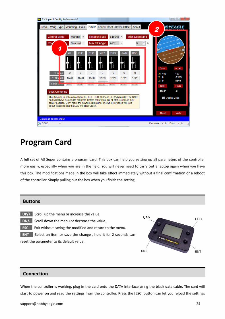
Program Card
A full set of A3 Super contains a program card. This box can help you setting up all parameters of the controller
more easily, especially when you are in the field. You will never need to carry out a laptop again when you have
this box. The modifications made in the box will take effect immediately without a final confirmation or a reboot
of the controller. Simply pulling out the box when you finish the setting.
Buttons
UP/+ Scroll up the menu or increase the value.
DN/- Scroll down the menu or decrease the value.
ESC Exit without saving the modified and return to the menu.
ENT Select an item or save the change , hold it for 2 seconds can
reset the parameter to its default value.
Connection
When the controller is working, plug in the card onto the DATA interface using the black data cable. The card will
start to power on and read the settings from the controller. Press the [ESC] button can let you reload the settings
1
2
again, after a reloading, the current data will be overwritten.
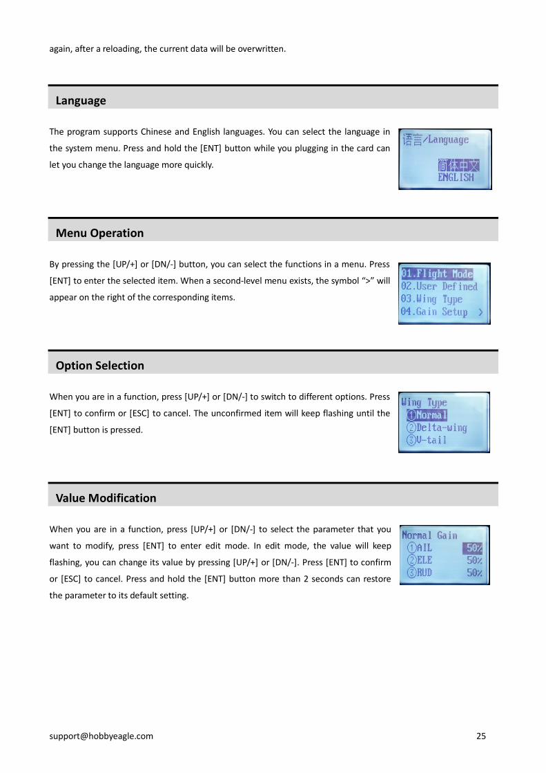
Language
The program supports Chinese and English languages. You can select the language in
the system menu. Press and hold the [ENT] button while you plugging in the card can
let you change the language more quickly.
Menu Operation
By pressing the [UP/+] or [DN/-] button, you can select the functions in a menu. Press
[ENT] to enter the selected item. When a second-level menu exists, the symbol “>” will
appear on the right of the corresponding items.
Option Selection
When you are in a function, press [UP/+] or [DN/-] to switch to different options. Press
[ENT] to confirm or [ESC] to cancel. The unconfirmed item will keep flashing until the
[ENT] button is pressed.
Value Modification
When you are in a function, press [UP/+] or [DN/-] to select the parameter that you
want to modify, press [ENT] to enter edit mode. In edit mode, the value will keep
flashing, you can change its value by pressing [UP/+] or [DN/-]. Press [ENT] to confirm
or [ESC] to cancel. Press and hold the [ENT] button more than 2 seconds can restore
the parameter to its default setting.

*Voltage Protector
After installing the gyro, the servos will move more frequently than before, it is
highly recommended that a reliable UBEC or ESC be used to provide sufficient
working current for the servos on the plane, otherwise the gyro may become
unstable by an occasional voltage drop. A large capacitor (3300uF/16V) can be used
to get a more stable and secure voltage level. You just need to simply plug it into
any open slot of the gyro or the receiver.
Specifications
Main Controller 32-bit MCU
Sensor 3-axis gyroscope and 3-axis accelerometer
Gyroscope Scale Range ±2000dps
Accelerometer Scale Range ±4g
Input Signal Standard PPM with center point 1520uS, or S.Bus serial data
Output Signal PWM max frequency 333Hz, 1520±500uS
Input Voltage 4.8V~8.4V
Operating Temp -10℃~50℃
Size 43×27×14mm
Weight 10g (excluding wires)