a1000 submersible level transducer proven performance in high solids environments · 2016-09-23 ·...
TRANSCRIPT

A1000 SUBMERSIBLE
PROVEN PERFORMANCE
IN HIGH-SOLIDS
LEVEL TRANSDUCER:
ENVIRONMENTS.

The A1000/157GSC Submersible LevelTransducer/Transmitter is a proven performer in high-solids environments,including sewage lift station wet wells and sludge sumps. It is equally effective inclean water level monitoring applications.The submersible system’s rugged simplicityeliminates the cost, clogging and com-plexity of other types of level sensing.
The A1000 senses liquid level excur-sions over a factory-calibrated, customer-specified range. It provides a signal totelemeter or record liquid level, or to senseflow rate in flumes, weirs and rivers.
Calibrated to the specific gravity of theliquid in which it operates, the transducermeasures the head-pressure imposed on itsbottom diaphragm face by the height ofthe liquid above it and translates theinformation into an electronic signal.
The 2-5/8'' diameter Teflon-faced orViton-faced diaphragm and state-of-the-artprecision pressure transducer mechanismare located in the lower assembly. Mountedat a fixed, submerged level, the lowerassembly has a type 316 stainless steel body.
The enclosed upper assembly housessystem signal conditioning, protectiveelectronics, the job connections terminalblock, and the expansion bag of the sealedbreathing system, a vital system whichnegates the effects of changes in atmos-pheric pressure and protects the sensorfrom environmental contaminants.
The connecting cable between theupper and lower assemblies has a1/2'' polyurethane jacket, a 3-conductorshielded AWG #16 cable, and anintegral rigid breather tube that is part ofthe sealed breathing system.
Advantages of the system include:• Solid-state electronics for accuracy,
reliability and economy.• Little or no maintenance required.• Sealed breathing system that protects
electronics from corrosive gases.• Rigid breather tube that cannot be
pinched as a result of installation, assuring barometric compensation.
• Integral transient protection.• High proof pressure that allows system
to withstand inadvertently excessivepressures on the sensing element.
• Seven pressure ranges (spannable downto 15% of element range).
• Easy field repair with stock parts.• Field calibration possible in most
applications.• Many options are available, including
level indication, special housing andenvironmental conditioning equipment.
S TA B L E , R E L I A B L E , S I M P L E
A1000 SUBMERSIBLE LEVEL TRANSDUCER
A1000 Features In Brief• 316 stainless steel construction with
PVC and Buna-N isolation ringsand 2-5/8'' Teflon®-coated or Viton®
coated Buna-N diaphragm.• Easy-to-run 1/2'' cable with integral
breather tube.• Sealed breather system.• Analog output.• Provides 1-5 VDC or 4-20 mADC
outputs.• Pressure range: 0-1, 0-5, 0-15, 0-30,
0-75, 0-150, 0-300 PSI.• Factory-calibrated, with field recali-
bration available.• Available in several standard cable
lengths. Custom lengths up to 1000' available by special order.
• Intrinsically safe when used withoptional IS1 Intrinsic Safety Barrier.
• Electronics are electrically isolatedfrom sensed media.
Teflon is a registered trademark of DuPont.
2

3
MOUNTING AND MEDIA The lower assembly is generally eitherpipe-mounted (1'' NPT) or suspendedwith a stainless steel cable in a verticalposition in the sump or reservoir to be sensed. Although it can be specifiedand furnished for any other mounting attitude, cable mounting is recommended
for easiest serviceability.The sensed media can be any type
compatible with the lower assemblyand cable materials (316 stainless steel,Teflon, PVC, Nitrile and urethane), but itmust be of a constant specific gravity.
CABLE SUSPENSIONMOUNTING KIT
LOWER ASSEMBLY DIMENSIONS
UPPER ASSEMBLYDIMENSIONS
Kit includes 2' long 1-inch NPT Type 316SS pipe with coupling, bolt, cable clampsand other hardware shown
P/N 601418-01
1/8-inch diameter, 7x19 SS cable; orderthe desired number of feet. Clamps are inKit P/N 601440-XX
Cable mounting is the preferred method for easeof serviceability.
The Pressure Range Table shows maximum full-scale ratings of the six standard elements. Note the highproof pressures shown. Each range can be furnished with a “Feet-of-Water” calibration to any desiredvalue from the maximum shown to as little as 15% of that figure.
ALTERNATECABLEMOUNTING
OPENSLOTFORCABLE
PRESSURE RANGE TABLEPRESSURE
RANGERANGES
PSIGPRESSURE/LEVELS
FT/WATER IN./WATERMAX. PRESS.
PSIG1.05.0
15.030.075.0
150.0
0 to 10 to 5
0 to 150 to 300 to 75
0 to 150
2.3111.5534.6569.3
173.25346.5
27.72138.6416.0832.0
2079.04158.0
2050
150150150225
TOP VIEW

4
THREE MODELS TO MATCH YOUR
ELECTRICAL SPECIFICATIONS
ELECTRICAL CONNECTIONS

5
STANDARD OPTIONS
Model 157GSCDLoop-powered, 4-20 mADC, 2-wire.Requires from 16 to 40 VDC loop powerto drive up to a 0-1400 ohm resistive load (meter, controller, circuitresistance, etc.). See the Table for looppower/load driving relationships. Transientprotection is provided, including a 3-element gas tube arrestor.
Model 157GSCI120 VAC-powered with a 10 VA currentdraw. Provides a 4-20 mADC outputsignal to drive a 0 to 1000 ohm resistiveload. Signal output loop is powered by thisunit at approximately 33 VDC. Thismodel includes a Manual Mode Switch
Model 157GSCE12 VDC-powered unit provides a precise1-5 VDC output signal capable ofdriving a 100 ohm or higher resistanceload. Supply voltage variations areaccommodated over a 10.5 to 30 VDC
range; with a 30 mADC maximum current draw. This model is well-suited tobattery operation. Varistor/resistor/diodetransient protection is provided.
1200 OHMS1000 OHMS800 OHMS600 OHMS400 OHMS200 OHMS
1400 OHMS – (MAXIMUM LOOP RESISTANCE)
5 10 2015 25 30 35 40
OPERATINGRANGE
LOOP SUPPLY VOLTAGE
MA
XIM
UM
DC
VO
LTA
GE
and Pot as well as a 0-1 mA or 0-1.999VDC attenuable drive circuit for anoptional digital panel meter or relatedcontrol. Transient protection is providedon both the 120 VAC power and the 4-20mADC output signal circuits.
USFilter Control Systems products can becustomized to meet your requirements.Many options are available. Please talk toyour USF Control Systems representativefor recommendations and price quotes.
Choose A Stainless Steel Upper Assembly.The housing of the upper assembly is furnished in Type 304 welded stainlesssteel under this option. The front door is hinged and gasketed. Nominal dimen-sions are generally similar to the basicmolded polyester housing.
Directly Connect The A1000 To A PipeOr Vessel By Converting It To An A3000.Convert the A1000 submersible leveltransducer into a submersible pressuretransducer that can be mounted on a pipe or vessel, giving the application theconvenience of a standard gauge-typepressure transducer with the survivabilityof a submersible. Used extensively in valvevaults that may occasionally be floodeddue to environmental conditions. Standard
connections include 3/4'' and 2'' femaleNPT.
Increase Safety To Your System ByAdding An Intrinsic Safety Barrier.The A1000 submersible level transducersystem is rendered intrinsically safe throughthe use of an IS1 barrier. See page 9 of this brochure for further informationregarding the use of IS1 barriers.
Add Convenience And ServiceabilityWith A Digital Panel Meter.The A1000 submersible level transducerupper electronics assembly is providedwith a 3.5 digit LCD level readout.
Improve Reliability In Damp Environments With ThermostaticallyControlled Condensation Protection.The A1000 submersible level transducerupper electronics assembly is providedwith an integral heater and high tempera-ture cut-out thermoswitch to protectinternal electronics from damage due tocondensation.

6
SUGGESTED SPECIFICATIONS For Model 157GSCDThe liquid level of the ______________shall be sensed by a USFilter ControlSystems Bulletin A1000, Model 157GSCDSubmersible Level Transducer. The transducer shall be a 4-20 mADC, 2-wire,16 to 40 VDC loop-powered type with its output signal directly proportional to the measured level excursion over a factory-calibrated range of zero to ___ feetof water.
For Model 157GSCEThe liquid level of the ______________shall be sensed by a USFilter ControlSystems Bulletin A1000, Model 157GSCESubmersible Level Transducer. The transducer shall be a 3-wire type to operate from a supply voltage of
For All ModelsThe Transducer shall be of the solid-statehead-pressure sensing type, suitable forcontinuous submergence and operationand shall be installed in accordance withmanufacturer’s instructions. The bottomdiaphragm face of the sensor shall beinstalled (recommend 6") ______ inchesabove the floor at elevation _________.The sensor shall be mounted in a locationand as shown on the job plans.
The transducer housing shall be fabricated of type 316 stainless steel with a bottom diaphragm 2-5/8'' diameter ofheavy-duty, limp, foul-free, molded Teflonbonded to a synthetic rubber back/seal.
A hydraulic fill liquid behind thediaphragm shall transmit the sensed pressure to a solid-state variable-capacitance transducer element to convertthe sensed pressure to a correspondingelectrical value. The sensed media shallexert its pressure against the diaphragmwhich flexes minutely so as to vary theproximity between an internal ceramicdiaphragm and a ceramic substrate to vary the capacitance of an electrical field
created between the two surfaces. A stable,hybrid, operational amplifier assemblyshall be incorporated in the transducer toexcite and demodulate the sensing mech-anism. The transducer shall incorporatelaser-trimmed temperature compensationand high-quality components and con-struction to provide a precise, reliable, stable output signal directly proportionalto the sensed pressure over a factory-calibrated range.
The transducer element shall incorporatehigh over-pressure protection and bedesigned to withstand intermittent over-pressures five times the full scalerange being sensed. Metallic diaphragmsshall not be acceptable in that they aresubject to damage or distortion. Sensingprinciples employing LVDTs, resistive or pneumatic elements shall not beacceptable.
The transducer/transmitter shall includeeasily accessible offset and span adjustmentsin the upper assembly. Span shall beadjustable from 100% down to 15% ofthe sensor range. Fine and coarse adjust-ments for both span and offset shall be
10.5 to 30 VDC and produce a 1-5 VDCinstrumentation signal in direct proportionto the measured level excursion over a factory-calibrated range of zero to ___ feetof water.
For Model 157GSCIThe liquid level of the _____________shall be sensed by a USFilter ControlSystems Bulletin A1000, Model 157GSCISubmersible Level Transducer. Thetransducer shall be a 4-wire type to operate on 120 VAC incoming power andproduce a 4-20 mADC instrumentationsignal into a 0-1,000 ohm load in directproportion to the measured level excursionover a factory-calibrated range of zero to___ feet of water.
SPECIFIED DESIRED CABLE LENGTHTO UPPER ASSEMBLY/TRANSMITTERENCLOSURE.
1'' NPT THREADED CONNECTION
3/4'' OR 2'' NPT THREADEDCONNECTION
11''
41/2''
SUBMERSIBLE LEVEL/PRESSURETRANSDUCER HOUSING (TYPE 316STAINLESS STEEL) WITH WATERTIGHTELECTRONICS/BREATHER CABLE TOTRANSDUCER SIGNAL CONDITIONING/TRANSMITTER MODULE AND SEALEDBREATHER BAG ASSEMBLY MOUNTEDIN AN ''ABOVE GRADE'' JUNCTIONBOX, OR CONTROL PANEL.
A3000

SUGGESTED SPECIFICATIONS (CONTINUED)
– OPTIONS
7
temperature changes and altitude as wellas prevent fouling from moisture andother corrosive elements.
The transducer assembly shall beinstalled where directed by theEngineer and connected with other system elements and placed in successfuloperation. It shall be provided with inputpower and output signal transient protection, associated control elements asspecified herein and in accordance withmanufacturer’s instructions.
provided, using 25-turn potentiometers.Offset and span adjustments shall be non-interactive, for ease of calibration.
The internal pressure of the lower transducer assembly shall be relieved toatmospheric pressure through a heavy-duty urethane jacketed hose/cable assembly with rigid breather tube and aslack PVC bellows mounted in theNEMA 3X fiberglass upper assembly. Thesealed breather system shall compensatefor variations in barometric pressure andexpansion and contraction of air due to
Safe Wiring BarrierProvide an intrinsically safe barrierbetween the upper and lower assemblies(or ahead of the entire transducer in thecase of the 157GSCD). The barrier shallrender the level sensing system suitable foruse in Class 1, Division 1, Groups A, B, Cand D, Class 2, Division 1, Groups E, Fand G, and Class 3, Division 1 hazardouslocations.
Digital Indicating Meter (LCD)Furnish a 3.5 digit digital panel meterwith a .5'' high numeric LCD display calibrated in “feet and tenths of a foot,”“inches of water” or other engineering
units as desired. The meter shall provide a 0-1999 count range produced by a 4-20 mADC signal. Lesser values shall be produced by an attenuated signal.Mount on the front hinged door of theupper assembly with a weatherproof clearpolycarbonate cover over the meter.
Condensation-ProtectiveHeater/ThermostatFurnish a 120 VAC powered resistorheater element and a sealed thermostat tokeep the internal temperature of the upperassembly above the dew point to preventproblems associated with condensation.
“A1000”SUBMERSIBLELEVEL SENSOR
CONTROLLER
Sewage or Stormwater Wet Well
SUGGESTED SPECIFICATIONS (CONTINUED)
– MOUNTING METHODS (SELECT ONE)
A. 1'' Pipe Mounting ClampsThe sensor shall be mounted using a vertical 1'' pipe (supplied by the contractor) and secured in place byUSFilter Control Systems Model 9GCL3 Type 304 stainless steel mounting clamps or equivalent.
B. Cable Suspension Mounting KitThe sensor shall be suspension-mountedusing a USFilter Control Systems cablesuspension mounting kit or equivalent,consisting of a 2' long 1-inch NPTType 316 stainless steel pipe with coupling, bolt, cable clamps andhardware along with the required length of 1/8 inch diameter 7 x 19stainless steel cable.

8
PERFORMANCE SPECIFICATIONS Type of TransducerHydrostatic head-pressure-sensing typemounted at a fixed elevation in an open(vented to atmosphere) sump or tank.
The height of water above the bottomdiaphragm imposes a pressure on the bottom limp interface diaphragm. Thispressure is transmitted by an internal oil fill to a gauge pressure type variable-capacitance transducer which converts the pressure to a directly proportionalelectrical signal. The power supply to thetransducer is supplied and regulated by anelectronics assembly in the upper housingwhich also accepts the output signal of thelower assembly transducer and providesspanning and offsetting as well as transientprotection and job connections.
Basic FunctionConverts water level excursions over a calibrated range to corresponding proportional electronic process controlsignal.
Pressure RangesSee Pressure Range Table, page 3.
Pressure OverloadSee Pressure Range Table, page 3.
Span AdjustmentsCoarse and fine. From 100% to 15% of range. Non-interactive with offsetadjustments. NOTE: Span is the algebraicdifference between zero level and the full-scale calibrated range of the transducer.
Offset AdjustmentsCoarse and fine. From 0 to 75% of range.Non-interactive with span adjustments.
Accuracy±0.3% best straight line of full span. Thistypical value includes combined effects oflinearity, hysteresis and repeatability.
Temperature RangeStorage: -20 to +80 degrees C (-4 to +176degrees F). Operation: 0 to +70 degrees C(+32 to +158 degrees F).
Temperature ErrorLess than 1/2 of 1% span over a 0 to 50degrees C (+32 to +122 degrees F) range.
Relative Humidity0-95%, non-condensing.
Stability over 1 year (typical)±1/2 of 1% of full span.
Job ConnectionsClamp type barriers terminals for AWG #14-22.
Media CompatibilityAny media compatible with #316 SS,PVC, Teflon, synthetic rubber and urethane and with a specific gravity of 1.0 or other constant. Refer specialrequirements to the factory.
Mounting AttitudeThe A1000 is factory-calibrated as a standard for use in the vertical position. Itcan be furnished calibrated for operationin any other desired attitude.
RepairableAll key parts of this transducer/transmittercan be repaired or replaced at the Factory.Easily field repaired.
9
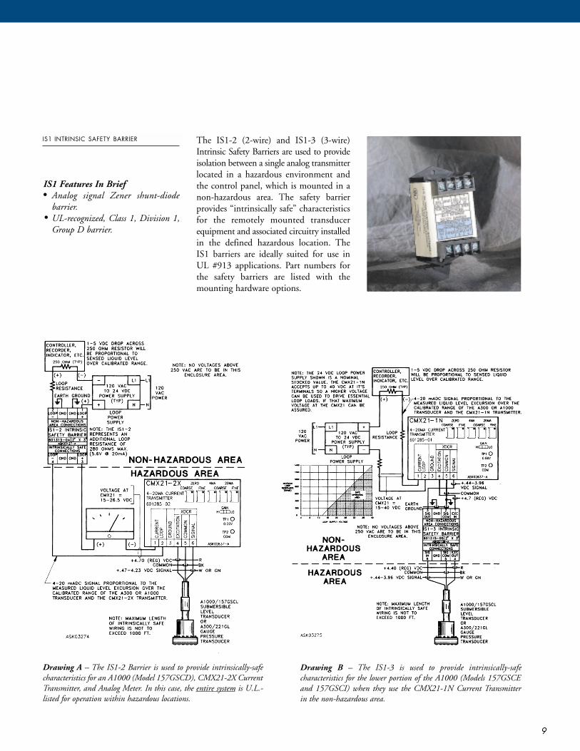
IS1 INTRINSIC SAFETY BARRIER The IS1-2 (2-wire) and IS1-3 (3-wire)Intrinsic Safety Barriers are used to provideisolation between a single analog transmitterlocated in a hazardous environment andthe control panel, which is mounted in anon-hazardous area. The safety barrierprovides “intrinsically safe” characteristicsfor the remotely mounted transducerequipment and associated circuitry installedin the defined hazardous location. TheIS1 barriers are ideally suited for use inUL #913 applications. Part numbers forthe safety barriers are listed with themounting hardware options.
Drawing A – The IS1-2 Barrier is used to provide intrinsically-safecharacteristics for an A1000 (Model 157GSCD), CMX21-2X CurrentTransmitter, and Analog Meter. In this case, the entire system is U.L.-listed for operation within hazardous locations.
Drawing B – The IS1-3 is used to provide intrinsically-safe characteristics for the lower portion of the A1000 (Models 157GSCEand 157GSCI) when they use the CMX21-1N Current Transmitter in the non-hazardous area.
IS1 Features In Brief• Analog signal Zener shunt-diode
barrier.• UL-recognized, Class 1, Division 1,
Group D barrier.

10
M O D E L S E L E C T I O N G U I D E
UPPER ASS’Y TYPED E I LBULLETINBULLETIN LOWER ASSEMBLY TYPE
XXX
X
X
XXXXXXXXXXXX
XXXXXXXXX
X
XXX
XXX
X
X
XXXXXXXXXXXX
XXXXXXXX5
X5
X
XXX
XXXXX
X
XXXXXXXXXXXX
XXXXXXXX5
X5
XXXXXX
XXX
X
X
XXXXXXXX
XXXXXX
XX
X
XXX
A1000A3000A3000MODEL
157GSCCODE
D
E
I
L1
CODE1.0n.n2
CODE1.05.015.030.075.0150.0300.0CODEnn3
CODE20304060nn
CODE01020304051112
2-5/8'' exposed Teflon diaphragmNPT port adaptor diaphragm cover – 3/4''NPT port adaptor diaphragm cover – 2.0''PRODUCT DESCRIPTIONSubmersible level transducerUPPER ASSEMBLYPower supply: 16-40 VDC, loop-powered, 2-wire typeOutlet signal: 4-20 mADCPower supply: 12 VDC, 3-wire typeOutlet signal: 1-5 VDCPower supply: 120 VAC, 4-wire typeOutlet signal: 4-20 mADCNo upper assembly Power supply: Regulated 6.25 VDC, 3-wire type
Output signal: 0-5 VDC not scaledSPECIFIC GRAVITY OF SENSED MEDIAWaterEnter specific gravity for fluid other than waterPRESSURE RANGE0-1 PSIG, 2.31 ft. water, 20 PSIG maximum pressure0-5 PSIG, 11.55 ft. water, 50 PSIG maximum pressure0-15 PSIG, 34.65 ft. water, 150 PSIG maximum pressure0-30 PSIG, 69.3 ft. water, 150 PSIG maximum pressure0-75 PSIG, 173.25 ft. water, 150 PSIG maximum pressure0-150 PSIG, 346.5 ft. water, 225 PSIG maximum pressure0-300 PSIG, 693 ft. water, 300 PSIG maximum pressureCALIBRATION RANGEFactory calibrated range in “Feet-of-water”CABLE LENGTH4
20 feet30 feet40 feet60 feetCustom length, contact factoryOPTIONS3.5 digit LCD display w/viewing windowCondensation protection heater and thermoswitch, 25WFreeze protection heater and thermoswitch, 100WBreather kitTCB terminal connection box w/breather kitIS1-2 intrinsic safety barrier, 4-20 mA output6
IS1-3 intrinsic safety barrier, 1-5 V output7
MOUNTING HARDWARE SELECTIONB100 9G CL3 stainless steel pipe mount clampsCable suspension mount fixtureCable suspension mount stainless steel cable (specify # of feet)
Order by Model Number, according to the following template, or by Part Number, according to the chart on the next page.
A _ _ _ _ – 157 GSC _ – _._ – _ _._ – _ _ _ – _ _ _ (_ _)–(_ _)–(_ _)Bulletin # Model # Specific Press. Calibration Cable Opt. 1 Opt. 2 Opt. 3
Upper Assembly Gravity Range Range (Ft.) Length
NOTES:1. Breather Kit option required. Also requires regulated 6.25 VDC source. Output not scaled.2. Contact factory for chemical compatibility of materials.3. Must fall within selected Pressure Range. Confirm that cable length is consistent with calibration range.4. Greater than 60 feet, consult factory.5. Requires 120 VAC service.6. Used when upper assembly mounted in hazardous area. Devices shipped loose for mounting in monitoring panel.
CMX21 analog signal conditioner module is potted.7. Mounted in upper assembly and used when upper assembly mounted in non-hazardous area.
PART NUMBERDESCRIPTION
11
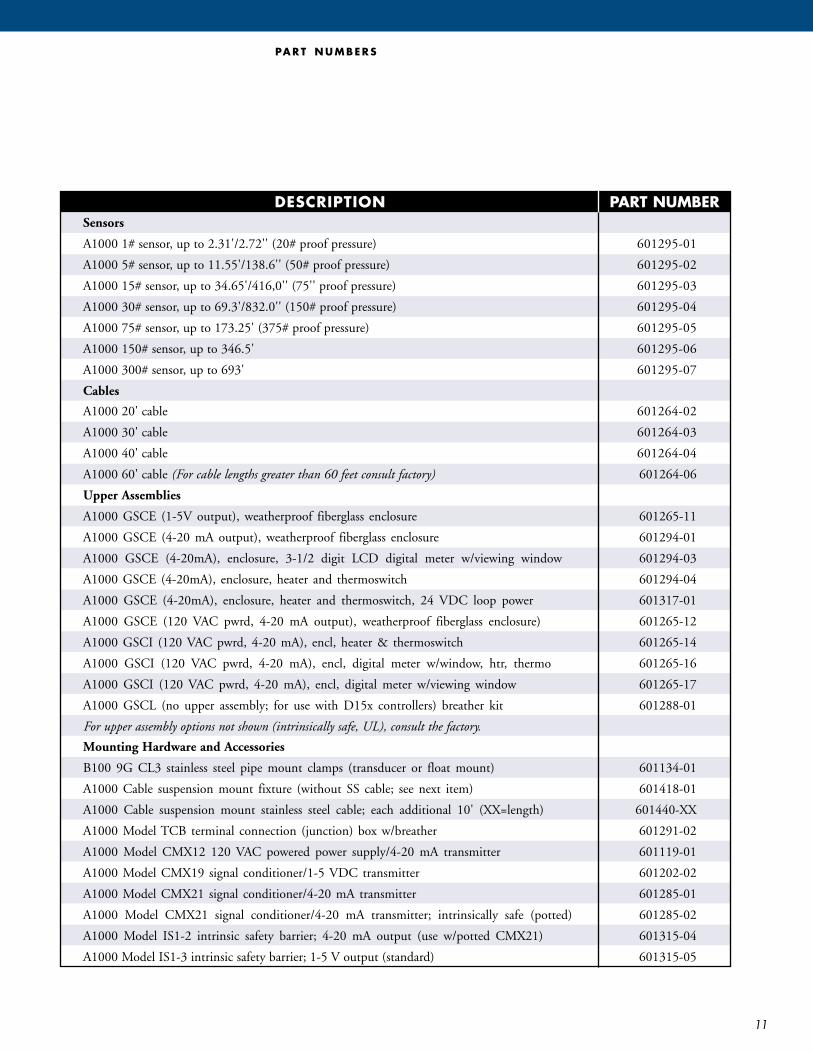
Sensors
A1000 1# sensor, up to 2.31'/2.72'' (20# proof pressure) 601295-01
A1000 5# sensor, up to 11.55'/138.6'' (50# proof pressure) 601295-02
A1000 15# sensor, up to 34.65'/416,0'' (75'' proof pressure) 601295-03
A1000 30# sensor, up to 69.3'/832.0'' (150# proof pressure) 601295-04
A1000 75# sensor, up to 173.25' (375# proof pressure) 601295-05
A1000 150# sensor, up to 346.5' 601295-06
A1000 300# sensor, up to 693' 601295-07
Cables
A1000 20' cable 601264-02
A1000 30' cable 601264-03
A1000 40' cable 601264-04
A1000 60' cable (For cable lengths greater than 60 feet consult factory) 601264-06
Upper Assemblies
A1000 GSCE (1-5V output), weatherproof fiberglass enclosure 601265-11
A1000 GSCE (4-20 mA output), weatherproof fiberglass enclosure 601294-01
A1000 GSCE (4-20mA), enclosure, 3-1/2 digit LCD digital meter w/viewing window 601294-03
A1000 GSCE (4-20mA), enclosure, heater and thermoswitch 601294-04
A1000 GSCE (4-20mA), enclosure, heater and thermoswitch, 24 VDC loop power 601317-01
A1000 GSCE (120 VAC pwrd, 4-20 mA output), weatherproof fiberglass enclosure) 601265-12
A1000 GSCI (120 VAC pwrd, 4-20 mA), encl, heater & thermoswitch 601265-14
A1000 GSCI (120 VAC pwrd, 4-20 mA), encl, digital meter w/window, htr, thermo 601265-16
A1000 GSCI (120 VAC pwrd, 4-20 mA), encl, digital meter w/viewing window 601265-17
A1000 GSCL (no upper assembly; for use with D15x controllers) breather kit 601288-01
For upper assembly options not shown (intrinsically safe, UL), consult the factory.
Mounting Hardware and Accessories
B100 9G CL3 stainless steel pipe mount clamps (transducer or float mount) 601134-01
A1000 Cable suspension mount fixture (without SS cable; see next item) 601418-01
A1000 Cable suspension mount stainless steel cable; each additional 10' (XX=length) 601440-XX
A1000 Model TCB terminal connection (junction) box w/breather 601291-02
A1000 Model CMX12 120 VAC powered power supply/4-20 mA transmitter 601119-01
A1000 Model CMX19 signal conditioner/1-5 VDC transmitter 601202-02
A1000 Model CMX21 signal conditioner/4-20 mA transmitter 601285-01
A1000 Model CMX21 signal conditioner/4-20 mA transmitter; intrinsically safe (potted) 601285-02
A1000 Model IS1-2 intrinsic safety barrier; 4-20 mA output (use w/potted CMX21) 601315-04
A1000 Model IS1-3 intrinsic safety barrier; 1-5 V output (standard) 601315-05
PA R T N U M B E R S

Control Systems1239 Willow Lake BoulevardVadnais Heights, MN 55110
800.224.9474 phone651.766.2700 phone
651.766.2701 fax
To find out more about how to put USFilter to work for you,
contact us at
For more information, visit our web site at
www.controlsystems.usfilter.com© 2001 USFilter
C O M P L E T E C O N T R O L C A PA B I L I T I E S
USFilter Control Systems offers a single,high-quality source for everything fromsimple level sensors to telemetry systemsto complex system control engineeringand software. Based in St. Paul, MN,USFilter Control Systems is part ofUnited States Filter Corporation, theleading global provider of industrial,municipal and residential water andwastewater treatment systems, productsand services.
As a major manufacturer/integratorwith an extensive selection of specializedproduct lines in the areas of SCADA andtelemetry, power equipment integration,automation and measurement, USFilterControl Systems is uniquely positionedto provide cost-effective, comprehensivesolutions for water, wastewater, and processcontrol and telemetry applications. Ourproducts and services encompass the following:• Complete design and engineering
services• Field services, including training and
troubleshooting
• Autocon SCADA systems• Consolidated Electric SCADA systems• Microcat control and telemetry
products• Remote terminal units and central
control units• Control and monitoring software• Process control and communications
computers• I/O boards, modems and power
supplies• Power equipment integration• Programmable logic controller systems• Programmable process controllers• Controllers and controller/alternators• Tank pump control systems• Pressure/level controllers• Pump flow and performance
monitoring• Flow switches and float switches• Intrinsic safety barriers• Level transducers and level sensors• Pressure transducers
CS-157GSC-BR-0101

CONTROL SYSTEMS 1239 WILLOW LAKE BOULEVARD VADNAIS HEIGHTS, MINNESOTA 55110 651 – 766 – 2700 Fax: 651 – 766 – 2701 www.control systems.usfilter.com
Product SpecificationCMX12 DC Power Supply/V-I Converter Module
The CMX12 Power Supply /V-I Converter Module is designed to interface with A300 and A1000 pressure transducers. It supplies power to the transducer and as the pressure varies with the liquid level the CMX12 receives a voltage signal and converts it to a powered 4-20mA signal. The CMX12 also can be connected to 0-1mA analog panel meter or a 0-1.999 VDC digital panel meter. The CMX12 has an Auto/Manual switch and a Manual simulate adjustment potentiometer, which can be used to simulate a voltage input, for calibrating and testing the current loop and related equipment. Part Number Description Application Notes6011190001 CMX12 Power Supply/V-I
Transmitter 157GCSI Upper Assembly
Specifications Physical Dimensions: 3”x 3 ½” x 1 ¾” Mounting: 3” Snaptrack Electrical Power Requirements: 120 VAC (+/- 10%) Onboard Transient protection provided.
Environmental Temperature Range Storage: -20 to 80 C (-4 to 176 degrees F) Operation: 0 to 70 C (32 to 158 degrees F) Temperature Error: Less than 1/2 of 1% span over a 0 to 50 C (32 to 122 degrees F) range. Relative Humidity: 0 – 95%, non-condensing.
CMX12_PS_Rev_C .doc

Product Specification CMX12 DC Power Supply/V-I Converter Module
Electrical Output Accuracy: +/-0.3% best straight line of full span. This typical value includes combined effects of linearity, hysteresis and repeatability 32 VDC Power Supply Out Typically used as a Current Loop Supply with maximum current loop
impedance of 1000 ohms. 12 VDC Power Supply Out. Typically used to power a CMX19 signal conditioner. @ 150mA max Terminal Description and Normal Operation Terminals Clamp Type. 14 - 22 AWG Terminal 1 L1 120VAC; 1/4 Amp Slo-Blo Onboard fuse
Transient protection: 130VAC Varistor surge arrestor
Terminal 2 N Neutral. Terminal 3 12 VDC Regulated output power Terminal 4 12 VDC Common. Terminal 5 1 –5VDC Analog input signal Terminal 6 Plus (+) output for a 4-20mA output (32VDC Loop Supply Voltage) Terminal 7 (-) 4 –20mA Loop Common Terminal 8 32 VDC output to supply.z Terminal 9 & 10 Meter output for 0-1mA or 0 –1.999 VDC. Selectable by a jumper. (J1) J1 Jumper Meter Output Selection: 0-1 mA analog or 0-1.999 VDC digital meter J2 Jumper Input Selection: 1 –5VDC or 4-20mA.
When using the CMX19 the jumper is set for 1-5VDC. Auto/ Manual Switch
In the Auto position the incoming signal comes from the transducer on Terminal 5. In the Manual position, the Manual Simulate Pot can be turned to simulate a signal. In either position, the output signal can be measured between Terminals 9 and 10.
© Copyright, 2002, USFilter Control Systems, Inc., All Rights Reserved
Page 2 of 3
CMX12_PS_Rev_C .doc

Product Specification CMX12 DC Power Supply/V-I Converter Module
CMX12_PS_Rev_C .doc
© Copyright, 2002, USFilter Control Systems, Inc., All Rights Reserved
Page 3 of 3
Testing Procedures Level/Pressure Simulation When the CMX12 is used with an A1000 transducer, flipping Auto/Manual (A/M) switch to the Manual position (M) and turning the Manual Simulate potentiometer with a small screwdriver can simulate the input signal (level/pressure). Rotating it clockwise will increase the output level. Ensure that the Auto/Manual switch is returned to the Auto (A) position when simulation is complete.

CONTROL SYSTEMS 1239 WILLOW LAKE BOULEVARD VADNAIS HEIGHTS, MINNESOTA 55110 651 – 766 – 2700 Fax: 651 – 766 – 2701 www.control systems.usfilter.com
Product SpecificationCMX19 Signal Conditioner/1-5VDC Transmitter
The CMX19 is a 12VDC powered signal conditioner module that supplies 6.25 VDC to a submersible transducer. It monitors the transducer output as the head-pressure varies with the changes in the liquid level. The CMX19 provides a scaled 1-5 VDC proportional analog output signal capable of driving a 100 ohm load such as controller or recorder. This module is well suited for battery operation and transient protection is provided which include varistors, resistors and diodes. Part Number Description Application Notes60120220001 CMX19 1-5 VDC out,
Transducer Excitation 8.25 VDC Obsolete –Replacement Part Only
60120220002 CMX19 1-5 VDC out, Transducer Excitation 6.25 VDC
Used in USFCS 157GSCE and 157GSCI Upper Assembly
Specifications Environmental Temperature Range Storage: -20 to 80 C (-4 to 176 degrees F) Operation: 0 to 70 C (32 to 158 degrees F) Temperature Error Less than 1/2 of 1% span over a 0 to 50 C (32 to 122 degrees F) range. Relative Humidity 0 – 95%, non-condensing. Physical Dimensions: 3”x 3 ½” x 1” Mounting: 3” Snaptrack Electrical Output Accuracy: +/-0.3% best straight line of full span. This typical value includes combined effects of linearity, hysteresis and repeatability Power Requirements: 10.5 to 30.0 VDC
CMX19_PS_Rev_B.doc

Product Specification CMX19 Signal Conditioner/1-5VDC Transmitter
Terminal Description and Normal Operation Terminals Clamp Type. 14 - 22 AWG wire Terminal 1 10.5 to 30.0 VDC Input Power Terminal 2 Power Supply Common
This is the same point on the board as Terminal 5 and the test point TP1. Terminal 3 1 to 5 VDC Output to Control Equipment
1 VDC is the zero pressure output voltage and 5 VDC is the full-scale span output voltage.
Terminal 4 Pressure Element Excitation Voltage Output (Red wire)
This is 6.25 +/-0.2 VDC. Terminal 5 Pressure Element Voltage Common (Black wire)
This is the same as Terminal 2 and test point TP1. Terminal 6 Pressure Element Input Signal (White wire)
This should be approximately 0.5 VDC at zero. Terminal 7 Shield tie point . No connection. Calibration/Testing Procedures The transducer is factory calibrated per customer specifications. Therefore user adjustments are normally not required. However, if re-calibration is necessary, the transducer can be re-calibrated within its range with a voltmeter and a small screwdriver. All adjustments and measurements are made on the CMX19 module. If the CMX19 is being calibrated in the field place the controls in “hand” or “off’” position to eliminate unwanted pump start/stops and alarms. Locate test points TP1, TP2, TP3 and adjustment pots - SPAN (fine and coarse), OFFSET (fine and coarse) and OUTPUT offset on the CMX19 board. Note: Clockwise rotation of the adjustments will increase the voltage. 1. Verify supply voltage between Terminal 1 (+) and Terminal 2 (common). It should be between
10.5 VDC and 30VDC. 2. Apply minimum pressure or level to the transducer. 3. Measure voltage between TP1 (common) and TP2 (+). Voltage should be 0.00 VDC. If not,
adjust the course and fine OFFSET pots.
© Copyright, 2002, USFilter Control Systems, Inc., All Rights Reserved
Page 2 of 3
CMX19_PS_Rev_B.doc

Product Specification CMX19 Signal Conditioner/1-5VDC Transmitter
CMX19_PS_Rev_B.doc
© Copyright, 2002, USFilter Control Systems, Inc., All Rights Reserved
Page 3 of 3
4. Measure voltage between TP1 (common) and TP3 (+). It should read 1.00 VDC. If not, adjust
the OUTPUT offset pot. 5. Apply maximum pressure or level to the transducer. 6. Measure voltage between TP1 (common) and TP3 (+). Voltage should be 5.00 VDC. If not,
adjust the course and fine SPAN pots. 7. To verify proper calibration repeat steps 3 through 6. If the voltages are correct then no further
adjustments are required and the transducer is calibrated.

CONTROL SYSTEMS 1239 WILLOW LAKE BOULEVARD VADNAIS HEIGHTS, MINNESOTA 55110 651 – 766 – 2700 Fax: 651 – 766 – 2701 www.control systems.usfilter.com
Product SpecificationCMX21 Signal Conditioner/4-20mA Transmitter
The CMX21 is a loop powered, 4 - 20mA, 2-wire, DC signal conditioner module that supplies 4.5 VDC to a transducer. It monitors the transducer output as the head-pressure varies with the liquid level and provides a 4-20mA output signal to a 0 – 1400 ohm resistive load; such as a Controller, Recorder and/or Meter. Part Number Description Application Notes6012850001 CMX21 Signal Conditioner/
4-20mA Transmitter Used in USFCS 157GSCD
1
6012850002 CMX21 Signal Conditioner/ 4-20mA Transmitter
Intrinsically Safe (potted) UL Rating File #E138857 YNE Class
2
Notes: 1. Requires 15-40 VDC power and provides transient protection, which includes a three-element
gas tube. 2. Requires 15-26.5 VDC power and Terminal 3 is not connected. Specifications Environmental Temperature Range Storage: -20 to 80 C (-4 to 176 degrees F) Operation: 0 to 70 C (32 to 158 degrees F) Temperature Error Less than 1/2 of 1% span over a 0 to 50 C (32 to 122 degrees F) range. Relative Humidity 0 – 95%, non-condensing. Physical Dimensions: 3”x 3 ½” x 1” Mounting: PN 6012850001 CMX21 Signal Conditioner is mounted on a 3” Snaptrack. PN 6012850002 is Intrinsically Safe and potted. It is mounted directly to a panel with 6-32 screws. Electrical Output Accuracy: +/-0.3% best straight line of full span. This typical value includes combined effects of linearity, hysteresis and repeatability
CMX21_PS_Rev_B .doc

Product Specification CMX21 Signal Conditioner/4-20mA Transmitter
Power Requirements: 15 to 40.0 VDC for CMX-21 Part Number 6012850001 The loop resistance determines the power requirements. 40 VDC is the maximum loop voltage and the maximum loop resistance is 1400 ohms. The greater the loop resistance the more voltage is needed. Terminal Description and Normal Operation Terminals Clamp Type: 14 - 22 AWG wire. Terminal 1 15 to 40.0 VDC Input Power
15 to 26.5 VDC Input Power for Intrinsically Safe CMX-21. See Note 2 Terminal 2 Power Loop Return
Power Loop Return for the 4 to 20mA signal. Polarization not required. Terminal 3 Ground
Connect to a good earth ground for lightning protection. If using an Intrinsically Safe Barrier. Do not connect to ground.
Terminal 4 Pressure Element Excitation Voltage Output (Red wire)
This should be approximately 4.5 +/-0.2 VDC. Terminal 5 Pressure Element Voltage Common (Black wire)
This is the same as Test Point TP2. Terminal 6 Pressure Element Input Signal (White wire)
This should be approximately 0.4 VDC at zero pressure
© Copyright, 2002, USFilter Control Systems, Inc., All Rights Reserved
Page 2 of 3
CMX21_PS_Rev_B .doc

Product Specification CMX21 Signal Conditioner/4-20mA Transmitter
CMX21_PS_Rev_B .doc
© Copyright, 2002, USFilter Control Systems, Inc., All Rights Reserved
Page 3 of 3
Calibration/Testing Procedures The transducer is factory calibrated per the customer specifications. Therefore user adjustments are normally not required. However, if re-calibration is necessary, the transducer can be re-calibrated within its range with a voltmeter and a small screwdriver. All adjustments and measurements are made on the CMX21 module. If the CMX21 is being calibrated in the field, place the controls in “hand” or “off’” position to eliminate unwanted pump start/stops and alarms. Locate test points TP1, TP2, TP3, TP4 and adjustment pots - 4mA pot, 20mA (fine and coarse), and ZERO (fine and coarse) on the CMX21 board. 1. Apply minimum pressure or level to the transducer. 2. Measure voltage between TP1 (common) and TP2 (+). Voltage should be 0.00 VDC. If not,
adjust the course and fine ZERO pots. Insert an ammeter in the current loop. (+TP3 and -TP4 on newer boards) Turn the 4mA adjustment pot until the meter reads 4.00mA. 1. Apply maximum pressure or level to the transducer. 2. With the ammeter in the current loop, turn the 20mA pots (fine and coarse) until the meter
reads 20mA. 3. Repeat the steps to verify proper calibration. Note: If a system is to be adjusted over a small portion of the transducer range, the GAIN jumper may need to be placed in the HI position. Trouble Shooting Loop Resistance Check The loop resistance can be measured with an ohmmeter. 1. Disconnect the power supply from the loop and jumper the two wires together. 2. Disconnect the loop wires from the CMX21. 3. With the ohm meter measure the resistance between the loop wires. When the test is complete, reconnect the power supply wires and the CMX21 wires.

CONTROL SYSTEMS1239 WILLOW LAKE BOULEVARDVADNAIS HEIGHTS, MINNESOTA 55110651 – 766 – 2700 Fax: 651 – 766 – 2701www.control systems.usfilter.com
Product SpecificationTP11/TP12/TP14/TP15
Transient Protection Products
tp11_15_PS_Rev_B .doc
Part Number Description Application Notes6011920001 TP11 Unpowered Voice-Grade
Phone LineSuppresses line transients onunpowered voice-gradetelephone circuits.
6011920002 TP12 Transient Protector 2-Wire 4-20mA Current Loop
Suppresses line transients on 2-wire current loop circuits.
6011920004 TP14 Transient Protector 3-Wire orPotentiometric
Suppresses line transients on 3-wire circuits or potentiometricsensors.
6011920005 TP15 Transient Protector 4-20mA, 2-Wire DC Circuit
Suppresses line transients on 2-wire current loop circuits withexternal power supply.
Specifications
Physical: All ModelsDimensions: 3”x 2.75”x 1”Mounting: 3” Snaptrack
Electrical: All ModelsPower Requirements: No power required.
Environmental: All ModelsTemperature Range Storage: -20 to 80 C (-4 to 176 degrees F)Operation: 0 to 70 C (32 to 158 degrees F)
Relative Humidity: 0 – 95%, non-condensing.
TP11 Transient Protector Unpowered Voice-Grade Phone Line
The TP11 Transient Protector is a three-stage surge suppression device, which can effectivelyattenuate most transients. It is designed for use in unpowered voice-grade telephone circuits. Thefirst stage consists of a rugged gas tube arrestor connected across the signal lines and ground. Thisstage is designed to suppress transients greater than 150 to 300 volts. The second stage consists oftwo varistors each connected between a signal line and ground. This stage is designed to suppressany transients less than 150 to 300 volts and clamp them to 22 VDC. The third stage consists of twospecial purpose, high-speed zener diodes, which suppress any remaining transients to 12 VDC.Four 25 ohm, 5-watt resistors, are connected between the stages to dissipate the potential energy ofthe transients.

Product Specification TP11/TP12/TP14/TP15Transient Protection Products
tp11_15_PS_Rev_B .doc© Copyright, 2002, USFilter Control Systems, Inc., All Rights Reserved
Page 2 of 3
TP12 Transient Protector 2-Wire 4-20mA Current Loop
The TP12 Transient Protector is a three-stage surge suppression device, which can effectivelyattenuate most transients. It is designed for use on 4-20mA current loop circuits. The first stageconsists of a rugged gas tube arrestor connected across the signal lines and ground. This stage isdesigned to suppress transients greater than 150 to 300 volts. The second stage consists of twovaristors each connected between a signal line and ground. This stage is designed to suppress anytransients less than 150 to 300 VDC and clamp them to 56 VDC. The third stage consists of twospecial purpose, high-speed zener diodes that suppress any remaining transient to 51 VDC. Four 25ohm, 5 watt resistors are connected between the stages to dissipate the potential energy of thetransients.
TP14 Transient Protector 3-Wire or Potentiometric
The TP14 Transient Protector is a three-stage surge suppression device, which can effectivelyattenuate most transients. It is designed for use in potentiometric or 3-wire circuits. In either case,the circuit would consist of a power supply, signal and signal return (common) connections. Thefirst stage consists of a rugged gas tube arrestor connected across the signal and power lines toground. This stage is designed to suppress transients greater than 150 to 300 volts. The second stageconsists of two varistors connected from the signal line and power supply line to ground. This stageis designed to suppress any transients less than 150 to 300 volts and clamp them to 39 VDC. Thethird stage consists of two special purpose, high speed zener diodes. These diodes suppress anyremaining transients on the signal line to 12 VDC and to 30 VDC on the power supply line. Four 25ohm, 5 watt resistors are connected between the stages to dissipate the potential energy of thetransients.

Product Specification TP11/TP12/TP14/TP15Transient Protection Products
tp11_15_PS_Rev_B .doc© Copyright, 2002, USFilter Control Systems, Inc., All Rights Reserved
Page 3 of 3
TP15 Transient Protector 4-20mA, 2-Wire DC Circuit
The TP15 Transient Protector is a three-stage surge suppression device, which can effectivelyattenuate most transients. It is designed for use in 4-20mA loops with a local power supply. The firststage consists of a rugged gas tube arrestor connected across the signal lines and ground. This stageis designed to suppress any transients greater than 150 to 300 volts. The second stage consists of avaristor connected between the signal return and ground. This stage is designed to suppress anytransients less than 150 to 300 volts and clamp them to 22 volts. The third stage consists of twospecial purpose, high-speed zener diodes that suppress any remaining transient to 12 volts. Four 25ohm, 5 watt resistors are connected between stages to dissipate the potential energy of thetransients. A 1 amp fuse is also included to protect the power supply.


DATA SHEET
IS1 INTRINSIC SAFETY BARRIER
The IS1 Intrinsic Safety Barrier is a specially engineered analog signal Zenershunt-diode barrier that is used between asingle USFilter analog transmitter (such asour A1000, A1200 or A3000) located in ahazardous environment and its associatedpump controllers, signal conditioners orother equipment.
The IS1 Barrier provides “intrinsicallysafe” characteristics within the transducerequipment and associated circuitry installedin the defined hazardous location, thusmaking the transducers suitable for operation within sewage lift station wetwells, stormwater-handling pump stations(which might inadvertently receive combustible liquids or produce com-bustible gasses), and many process applications.
The IS1 is made in 2-wire (IS1-2) and3-wire (IS1-3) versions to be used in 4-20 mADC, 2-wire and 1-5 VDC, 3-wiretransducer systems, respectively. It has been tested and is listed by UnderwritersLaboratory, Inc., as Process Control Equipment (QUZW). The transducer andsignal conditioning system elements foruse with the IS1 Barriers are UL-listedunder Intrinsically Safe Equipment andSystems (OERX).
The IS1-2 Barrier is designed to makeits associated transducers and circuitrysuited for Class 1, Division 1 or 2, Groups C and D; Class II, Division 1 or 2,Groups E, F and G; and Class III hazardouslocations as defined by the NationalElectrical Code (NEC). The IS1-3 Barrieris suited for use with those locations, aswell as Class I, Division 1 or 2, Groups Aand B.
The IS1 barriers are ideally suited forapplications requiring compliance withUL913 procedures pertaining to electricalcontrol panels with intrinsically safeextensions to hazardous areas.
IS1 PRODUCT SPECIFICATIONSCable Lengths: Interconnecting cable inthe hazardous area is not to exceed 1000 ft.Maximum Safe Area Voltage: 250 VACMaximum Operating Voltage (IS1-2):26.5 VDCMaximum Operating Voltage (IS1-3):6.5 VDCOutside Dimensions: 4'' H x 2'' W x 2-1/4'' D
IS1 TYPICAL SPECIFICATIONSThe transducers shall interface to the control circuitry via an intrinsically safebarrier. The barrier shall provide anintrinsically safe interface for analog-signal-producing devices located in ahazardous area rated Class I, Group A, B,C, and D, and Class II, Groups E, F, andG. The intrinsic safety barrier, the level/pressure transducer, and all relevant circuit elements shall be UL-listed.
Model IS1-2 intrinsic safety barrier; 4-20 mA output (use w/potted CMX21) 601315-04
Model IS1-3 intrinsic safety barrier; 1-5 V output (standard) 601315-05
DESCRIPTION PART NO.
The NEC Handbook defines hazardous locations by Class,Division and Group as follows:Class I Locations – Are those inwhich flammable gasses or vaporsare or may be present in the air inquantities sufficient to produceexplosive or ignitable mixtures.Class II Locations – Are thosewhich are hazardous because ofthe presence of combustible dust.Class III Locations – Are thosewhich are hazardous because ofthe presence of easily ignitablefibers or flyings, but in which suchfibers or flyings are not likely to bein suspension in air in quantitiessufficient to produce ignitablemixtures.Division 1 – Locations in whichhazardous concentrations in the airexist continuously, intermittently,or periodically under normal operating conditions.Division 2 – Locations in whichhazardous concentrations are handled, processed, or used butare normally confined withinclosed containers or closed systemsfrom which they can escape only in case of accidental ruptureor breakdown.Group A – Atmospheres contain-ing acetylene.Group B – Atmospheres contain-ing hydrogen, or gasses or vaporsof equivalent hazard, such as manufactured gas.Group C – Atmospheres contain-ing ethyl-ether vapors, ethylene,or cyclopropane.Group D – Atmospheres contain-ing gasoline, hexane, naphtha,benzine, butane, propane, alcohol,acetone, benzol, lacquer solventvapors, or natural gas.Group E – Atmospheres contain-ing metal dust, including alumi-num, magnesium, and their com-mercial alloys, and other metals ofsimilarly hazardous characteristics.Group F – Atmospheres contain-ing carbon black, coal, or coke dust.Group G – Atmospheres contain-ing flour, starch, or grain dusts.
NEC DEFINITION OF HAZARDOUS LOCATIONS
CS-IS1-DS-1200
DATA SHEET
IS1 INTRINSIC SAFETY BARRIER
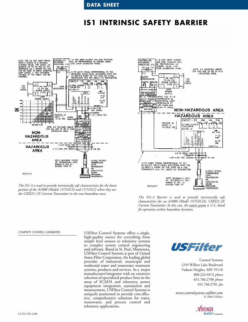
The IS1-2 Barrier is used to provide intrinsically safe characteristics for an A1000 (Model 157GSCD), CMX21-2XCurrent Transmitter. In this case, the entire system is U.L.-listedfor operation within hazardous locations.
The IS1-3 is used to provide intrinsically safe characteristics for the lowerportion of the A1000 (Models 157GSCD and 157GSCI) when they usethe CMX21-1N Current Transmitter in the non-hazardous area.
USFilter Control Systems offers a single,high-quality source for everything fromsimple level sensors to telemetry systemsto complex system control engineeringand software. Based in St. Paul, Minnesota,USFilter Control Systems is part of UnitedStates Filter Corporation, the leading globalprovider of industrial, municipal and residential water and wastewater treatmentsystems, products and services. As a majormanufacturer/integrator with an extensiveselection of specialized product lines in theareas of SCADA and telemetry, powerequipment integration, automation andmeasurement, USFilter Control Systems isuniquely positioned to provide cost-effec-tive, comprehensive solutions for water,wastewater, and process control andtelemetry applications.
COMPLETE CONTROL CAPABILITIES
Control Systems1239 Willow Lake BoulevardVadnais Heights, MN 55110
800.224.9474 phone651.766.2700 phone
651.766.2701 fax
www.controlsystems.usfilter.com© 2000 USFilter