a x-&i underwater ia acoustic source for the infrasonic ... · x-&i underwater ia acoustic...
TRANSCRIPT

NRL Report 7967
AX-&i iA Underwater Acoustic Source for the
Infrasonic and Low-Audio-Frequency Range(USRD Type J13 Transducer)
A. MARK YOUNG
C1 Standards BranchUnderwater Sound Reference Division
30 December 1975
NAVAL RESEARCH LABORATORYUnderwater Sound Reference Division
P. 0. Box 8337, Orlando, Fla. 32806
Approved ror public release: distribution unlimited.

UNCLASSIFIED
SECURITY CLASSIFICATION OF THIS PAGE (47Wen Data Entered)
REPORT DOCUMENTATION PAGE READ INSTRUCTIONSBEFORE COMPLETING FORM
t REPORT UMB R j2. GOVT ACCESSION No. 3. RECIPIENT'S CATALOG NUMBER
NRL ft ,7 94. TITLE ( SuhtItie) ,. TYPE OF REPORT & PERIOD COVERED
AN UNDERWATER ACOUSTIC SOURCE FOR THE Final rep _rt,on one part
INFRASONIC AND LOW-AUDIO-FREQUENCY RANGE of thd prc6tlm.(US TYPE J13 TRANS ) 6. PERFORMING ORG. REPORT NUMBER
7. AUTHOR(&) 1S. CON'r.!,'Z Jt OR GRANT NUMBER(O)
SA. Mark Young
9. PERFORMING ORGANIZATION NAME AND ADDRESS - 10. PROGRAM ELEMENT. PROJECT, TASK/N~vl Reearc Labratoy <l -- AREA A WORK UNIT NUMBERSNxava1 Research LaboratoryUnderwater Sound Referenc- Division NRL Sp2-3D,P.O. Box 8337, Orlando, Fla. 32806 ProjectRF -121 4O3-440 2"
It. CONTROLLING OFFICE NAME AND ADDRESS 12. REPORT DAt. _
Department of the Navy j/ 3 b "i:975/Office of Naval Research 13. NUMBER OF PAGES
Arlington, Va. 22217 ii + 1914. MONITORING AGENCY NAME & ADDRESS(i different from Controlling Office) I5. SECURITY CLASS. (of this report)
t7 I -! / / - '/' / .1 Unclassified
- ISa. DECL ASSI FICATION/DOWNGRADINGSCP EDULE
16. DISTRIBUTION STATEMENT (of this Report)
i,
Approved for public release; distribution unlimited.
17. DISTRIBUTION STATEMENT (of the abstract entered In Block 20, It different from Report)
IS. SUPPLEMENTARY NOTES
19. KEY WORDS (Continue on reverse aide It necessary and Identify by block number)
Electrodynamic acoustic transducerLow-audio-frequency transducerTransducer designTr nsducer construction
\Underwater acoustic transducer20 BTRACT (Continue on reverse eide it necee.ay and Identify by block number)
-i" An electrodynamically driven underwater sound source with an acousticoutput of 1.349 W has been developed. Adapted in various configurationsincluding as many as nine driving units, this transducer fulfills asubstantial portion of the needs for low-audio-frequency underwater soundsources.
DD IFORM 3 1473 EDITION OF I NOV 65 IS OBSOLETEJAN 7 SIN 0102-014-6601 1 i UNCLASSIFIEDSECURITY CLASSIFICATION OF THIS PAGE ("en Date Entered)

Contents
Introduction ....... .. ............................. 1
Design Considerations ..... ... ........................ 2
Construction ....... .. ............................. 4
Analysis ........ .. ............................... 7
Conclusions ..... .. .. ............................. 11
Acknowledgments ..... ... ........................... 11
References ...... ... .............................. 11
Appendix A. Determination of Values for Elements of the J13Equivalent Circuit .... ................... .12
Figures
I,
1. USRD electrodynamic transducers types J9, Jll, and J13 ... ...... 1
2. Summary of design considerations ....... ................. 5
3. Sectional view of USRD type J13 transducer ...... ............ 6
4. Equivalent circuit for USRD type J13 transducer,classical analogy ......... ........................... 7
5. Equivalent circuit for USRD type J13 transducer,mobility analogy ............ ......................... 8
6. Equivalent circuit for USRD type J13 transducer, mobility] dnalogy for clectronic circuit analysis by time-sharing
computer program .......... ............................ 9
7. Comparison of USRD type J13 transmitting current responsedata obtained by measurement with results from equivalentcircuit calculations ........... ....................... 10
Table
I. Some operating characteristics of USRD type J9, Jll,and J13 transducers ........... ....................... 2
ii

AN UNDERWATER ACOUSTIC SOURCE FOR THE
INFRASONIC AND LOW-AUDIO-FREQUENCY RANGE ,
(USR) Type J13 TRANSDUCER)
Introduction
About twenty years ago, the Underwater Sound Reference Divisiondeveloped the first in a series of broadband, electrodynamically drivensound sources for the audio-frequency range, the USRD type J9 transducer,which was intended primarily for use as a calibration source. Withinless than ten years after the J9 was introduced, the requirements for amore powerful sound projector prompted development of a somewhat largertransducer designated USRD type Jll. Ever since the time they weredeveloped, both of these transducers have been used extensively inlaboratory and ocean applications.
Growing interest in at-sea calibration during the late 1960's andearly 1970's stimulated development of the USRD type J13 infrasonic andlow-audio frequency transducer, which is capable of radiating more powerat lower frequencies than either of the two predecessors. Although thedesigns of the J9, Jll, and J13 transducers are based on the same oper-ating principles, unique features of the J13 provide significantlygreater power and adaptability. The three transducers are comparedbriefly in Fig. 1 and Table 1.
:1 --Iri •i
Fig. 1. USRD electrodynamic transducers types J9,Jll, and J13 (left to right).
.!1

Table 1. Some operating characteristics of USRD trans-ducers types J9, Jill, and J13.
4 USRD Frcq Max electr Max acoust Weighttransducer range input power output power in air
type (kHz) (W) (W) (kg)
J9 0.04-20 20 0.013 9
Jll 0.02-12 200 0.269 46
J13 0.01-3 250 1.349 55
Design Considerations
The primary design goals for the J13 transducer were:
a. Maximum useful bandwidth in the infrasonic and low-audiofrequency range.
b. Maximum acoustic output for the smallest possible size andlightest weight.
The parameters affecting these goals are best understood by inspectionof the fundamental equations for an electrodynamically driven piston atthe end of a long tube.
The bandwidth in which the transducer may provide a flat response isbounded on the low end by the frequency 0 at which the total mass MT
resonates with the total system compliance CT so thatTT
The upper limit of this band is that frequency above which the diaphragmno longer moves as a piston; that is, the phase across the diaphragm faceis no lonyer constant. This frequency is a function of the geometricalshape and dimensions of the diaphragm and of the material from which itis made.
Equations describing the output acoustic pressure from a circularpiston at the end of a long tube in terms of electrical input parametersand as a function of frequency have been developed by Sims and others[1,2,3]. For a piston operating above the resonance frequency w0 ' thetransmitting current response measured at a distance of one meter may be
represented by
-p (B )2POcORORR
i n[RR2 + (WMd + XR) 2] (2)
2

where p is the acoustic pressure at one meter, i is the driving current,B is the flux density in the gap of the magnet, I is the length of theconducting coil interacting with B, p0 is the density of water, c0 is thespeed of sound in water, R is the directivity factor, RR is the series
radiation resistance, w, is the angular frequency, Md is the mass of the
diaphragm, and XR is the series radiation reactance.
Equation (2) may be rewritten as the acoustic pressure at one meter:
p = Bki 2 0 0aROR 2 (3)147[RR + (WMd + XR)
Relative effects of the design parameters become evident upon inspec-tion of the preceding equations: bandwidth can be increased by reducingthe resonance frequency and increasing the stiffness-to-mass ratio ofI:he diaphragm; the acoustic output can be increased by increasing theforce factor Bki and decreasing the total effective mass. It is readilyapparent that some of these requirements are contradictory: the firstgoal suggests that the total mass be increased, but the second goalrequires that the mass be decreased.
The flux density in the gap of the magnet is determined primarily bythe type of magnetic material used and the ratio of its volume to thatof the gap. The maximum length of coil conductor (more correctly themaximum product of k and i) is limited by the volume of the gap and themaximum allowable input electrical power, which is largely controlledby the rate of heat dissipation from hne driving coil.
The total mass is comprised of the diaphragm mass and the massreactance due to the water load, the latter being a function of thediaphragm radius a and the medium; therefore, a large portion of thetotal mass (in many cases the largest portion) is fixed when the diaphragmradius is chosen and becomes unavailable as a parameter to be compromised
by design.
For a source whose size is small in comparison with a wavelength, inthe propagating medium, it can be shown that the radiated acoustic poweris determined by the radiation resistance acting on, and the volumevelocity generated by, the source [4]. Radiation resistance, like radia-tion reactance, depends upon the diaphragm radius and the medium, and itis also directly proportional to the square of the frequency; therefore,to maintain a constant output with decreasing frequency, the volumevelocity must increase at the same rate that the radiation resistancedecreases. From the definition of volume velocity as the product of theradiator surface area and the velocity of that surface, it is seen thatthe surface displacement is inversely proportional to the square of thefrequency and that there is a minimum frequency at which the maximumacoustic output occurs. This frequency is determined by the maximum
3

allowable displacement of the diaphragm and is computed from
W = 2(pr/$p0) /a, (4)
where p is the sound pressure measured at distance r when using maximumelectrical input, and C is the maximum allowable root mean square dis-placement of a diaphragm whose radius is a. At lower frequencies, thesound pressure generated is proportional to the radiation resistance andis, therefore, decreasing at 12 dB per octave.
Opposing requirements are also found at the periphery of the piston.The high radiation impedance of the medium acting on the piston requiresmaintaining high acoustic impedance in the vicinity of the diaphragm;any areas of low acoustic impedance permit power to be "shunted" past thepiston. Thus, the piston suspension must be mechanically compliant tomaintain the low resonance frequency and allow for large piston displace-ment, but must present a high acoustic impedance to the surrounding medium.
A further design consideration related to the resonance frequency and,therefore, to the output at low frequencies, is the depth-compensation orpressure-release system. A most effective pressure release for highlycompliant systems is provided by a gas compensation system; however, suchsystems are prone to performance problems. In Eq. (1)' the total mass MT
is the sum of the diaphragm mass and the mass reactance of the water load,and the total compliance CT is the effective net compliances of the dia-
phragm suspension and the volumes contained in the compensation system.The diaphragm mass, radiation mass, and suspension compliance are allindependent of the ambient hydrostatic pressure. If it is assumed tha.there is a rigid-walled chamber behind the piston, however, the compli-aceof the gas system is given by
C = P0V0/yp2 , (5)
where p0 and V, are the initial gas pressure and volume, respectively,
y is the ratio of the specific heats of the gas at the two pressures,and p is the pressure at the operating depth. Equations (1) and (5) showthat the resonance frequency is proportional to depth; this effect can beminimized for a given maximum operating depth, but it cannot be eliminated.
The maximum operating depth attainable with this type of compensationis determined by the residual volume behind the piston and the totalavailable volume of compensation gas.
Figure 2 graphically summarizes the major design considerations that
have been discussed.
Construction
The USRD type J13 transducer represents the end product of a series
4

(I AI
Pt q~,c -1Ifllls fc 1.4eecy
Fig. 2. summary of design considerations.
of design compromises between the many contradictory requirements out-lined in the preceding discussion. Figure 3 shows the most importantfeatures of the J13 referred to in the functional description that follows.
Flux density in the gap of the magnet is generated by one 3.6-kgAlnico 5-7 magnet and three Ainco copper-plated magnetic iron pole pieces.Spurious resonences in the mgnet ass.:mbly are damped by filling voidswith a matrix of lead shot and epoxi cement. The magnet is charged bypassing a momentary 220-;, dc current through the charging coil encapsu-lated in the surrounding ..poxy matrix. The one-piece piston and coilform (10-cm diam) carrzJ 212 -urns of AWG-30 copper wire and is suspendedfrom a single neoprene ircums-4rential seal. In spite of natural rubber'smany desirable mechanical prctierties, this seal is made of neoprene be-cause of its superior durability under the operating conditions of thehigh-temperature environment. Mechanical compliance of this seal wasincreased toward that of natural rubber by means of convclutions moldedin the seal body. The piston (voice) coil is centered in the gap of themaqnet by the center guide pin and Teflon bushing assembly, which servesalso to counteract the buoyant force acting on the air-backed conicalpiston section. Front and rear mechanical stops prevent the piston fromexceeding its maximum allowable displacement. The magnet gap and front
* cavity are filled with castor oil, which acts as a coupling medium tothe water and provides the high acoustic impedance required at theperiphery of the piston. The neoprene acoustic window provides a water-tight seal for the oil-filled cavity.
Changes in hydrostatic pressure acting on the piston are compensatedby a passive pneumatic system, the heart of which is an elastic bag madeof a butyl rubber compound whose permeability to water is very low. Asthe operating depth increases, the bag is compressed by the water headand increases air pressure behind the piston for compensation to depthsof about 22 m.
5

1 2 3 4 5 6
1 5
15L I_ 7)_
• II,
. '~
Fig. 3. Sectional view of USRD type J13 transducer: (1) rear mechanicalstop, (2) corrugated neoprene acoustic window, (3) piston and coil form,(4) front mechanical stop, (5) oil-filled front cavity, (6) outer polepiece, (7) center guide pin and Teflon bushing assembly, (8) driving coil,(9) inner front pole piece, (10) oil flow holes, (11) neoprene circumferen-tial seal, (12) lead-epoxy potting compound, (13) Alnico 5-7 magnet, (14)charging coil, (15) back pole piece, (16) waterproof electrical connector,(17) air filling valve, (18) compliant butyl rubber pressure-compensationbag, and (19) housing back plate.
(4 fon mchnialstp,(5 olfile fon cviy,(6 ote 6l

CIS* 104 4f
Az Y,
clsia anloy A is th ptnae, A 1" is th seal
- , 4W' , A-1A'-
area, ;,nd A2 is the area of the case.
The maximum acoustic output of the device is limited by the maximumallowable electrical input to the coil, which has been determined experi-
. mentally to be 250 W for continuous operation at frequencies above that~at which the output is limited by displacement of the piston.
) Perhaps the most important secondary design feature of the J13 trans-
H H
ducer is its modular element construction that provides unique adaptabilityto various housings and configurations. Among the successful adaptationsthat have been made to date are its use in two deeper-submergence systemsand in a three-element planar array [5]. Its use in even larger arrayshas been proposed [6).
'j Analysis
The equivalent mechano-acoustical circuit shown in Fig. 4 was developedfrom the various masses, compliances, resistances, and radiation impedancesassociated with the transducer; the electrical portion of the circuit is
~omitted for the sake of clarity. With the masses of the piston and trans-
l ducer case expressed in acoustical units, it is easy to see that the' forces applied across each transformer are equal but opposite in phase.
The transformer ratio 1: (A + AI1) is obtained because the force impressed
I on piston area A is equal in amplitude and phase to the force on the seal
H '
area AV permitting transformers 1:A and :A1 that couple these portions
of the circuit to be combined. The compliances of the piston and sealair cavities are coupled together by the air slit between them; these com-
1 pliances are coupled to the compensation cavity by their respective passages.
The currents U c , Ub , and U represent the volume velocities associated
with case, back, and piston radiation, respectively; u1 and u2 are linear
area ~n ~2is he reaof he ase

velocities; Bki represents the force generated by the current-carryingcoil moving in the magnetic gap.
Inspection of the equivalent circuit shows the importance of having alarge case mass relative to that of the piston and the necessity for main-taining high acoustic impedance at the oil-filled slit and flow holes.
Several of the circuit elements are depth dependent. The compliancesof the piston cavity C, compensation cavity C2, and seal cavity C de-
21 3crease as hydrostatic pressure increases, while the water mass in the com-pensation cavity increases with depth.
Among the simplifying assumptions made in the derivation of the equiva-lent circuit were, for example, the omission of all the effects of acousticpressure in the water upon various parts of the transducer and the trans-formers necessary to couple two volume velocities to the compensation bagcompliance and water mass. Also, the motion of the diaphragm was con-sidered to be only that of a rigid piston.
The circuit in Fig. 4 is based on the classical or impedance analogy(voltage analogous to pressure, current analogous to volume velocity),which is inconvenient for the analytical description of a magnetic trans-ducer. A more convenient version of the equivalent circuit for detailedanalysis is the mobility analogy (voltage analogous to volume velocity,current analogous to pressure) shown in Fig. 5, wherein the electricalelements have been included and the transformers have been removed. Theelectroacoustical "turns ratio" N is determined by the transduction prin-ciple used and the dimensions of the radiators involved. The denominator
SA---- SVV-, N 2/R R¢
22
'He L - "
2 'C N IRp
~B~ 2 c M/N
0
2P
02 2 N MC/Atat I 2/,,, MHA, N,
Fig. 5. Equivalent circuit for USRD type J13 transducer,
mobility analogy; N2 = (B£) 2 /[A 2 - (A + AI)] 2.
I ....
N N
'IT
01 9 8/0
2 2 5 N 2CR 8
I 'jJ j .V 4 N
.9. NC Ol 11 zCkl-% , " k., l .
4- 1 I - i M"",A- --84 1 86"/ k 11
M N2
-. I : /
% ~MR/N
:15
. i 816 -I
'0
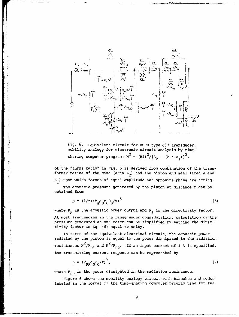
SFig. 6. Equivalent circuit for USRD type J13 transducer,mobility analogy for electronic circuit analysis by time-
N2 ~ 2 .
sharing computer program; N 2 = (B£) /[A 2 - (A 9. A ) 1
,, of the "turns ratio" in Fig. 5 is derived from combination of the trans-' . former ratios of the case (area A2 ) and the piston and seal (area A and
829: 2
A 1I ) upon which forces of equal amplitude but opposite phase are acting.The acoustic pressure generated by the piston at distance r can be
obtained from
sa = (p/r) (P P0 cR(/ (6)
Swhere P A is the acoustic power output and R a is the directivity factor.At most frequencies in the range under consideratin, calculation of thepressure generated at one meter can be simplified by setting the direc-
tivity factor in Eq, (6) equal to unity.A1 In terms of the equivalent electrical circuit, the acoustic power
T c i sgradiated by the piston is equal to the power dissipated in the radiationresistances N2/RR and N2/RR2' If an input current of 1 A is specified,
the transmitting current response can be represented byp = (PRRPCOc/,a) (7)
where PRR is the power dissipated in the radiation resistance.
Figure 6 shows the mobility analogy circuit with branches and nodeslabeled in the format of the time-sharing computer program used for the
2 2

electronic circuit analysis. The dashed line shown between branches 5and 6 represents the compressed metal-fiber acoustic resistors used ateach end of the magnet passage to damp the resonance of the hcle and
pistoA cavity.
Values for the elements of the circuit were obtained by either directmeasurement, calculation from measurements of motional impedances of thetransducer under various loading conditions, or were computed . Thevalues used and their derivations are outlined in Appendix A.
Because power dissipated in a branch can be selected as an output ofthe analysis program, the power dissipated in branches 26 and 28 representsthe acoustic power radiated from the piston; and the power dissipated inbranches 9, 11, 15, and 17 represents the acoustic power associated withthe back and case radiation.
The transmitting current response obtained from the power dissipatedin the radiation resistance branches and Eq. (7) is compared with themeasured response of the transducer in Fig. 7. The apparent discrepanciesbetween the measured and calculated results seen in these curves arelargely attributable to the effects of the simplifying assumptions madein the circuit derivation and to the difficulties in assigning accuratevalues to some of the circuit elements. For example, resolution of thevalues obtained from the motional impedance measurements made at very lowfrequencies is, at best, only fair; and it is difficult, if not impos-sible, to measure or calculate values for the compensation cavity-compensation bag compliance combination under actual operating conditions.The positive slope of the curve for values measured between 1500 and3000 Hz is caused by flexural resonances in the piston that would not beaccounted for by calculated values because of the earlier assumption thatthe diaphragm moves as a rigid piston.
170 L
t60
'o150
'40
.._____ __. ___ ______ ____ _____, ____ _____ ___ 5S001 005 01 05 1 0 50
Feqency fn kHZ
Fig. 7. Comparison of USRD type J13 transmitting
current response data obtained by measurements(solid-line curve) with results from the equiva-lent circuit calculations (dashed-line curve).
10

Conclusions
The USRD type J13 transducer, which is based on an old transductionprinciple, is a unique and adaptable underwater acoustic source. The J13radiator, adapted in various configurations, fulfills a substantial por-tion of the underwater acoustic community's needs for low-audio-frequencysources. This transducer has been consistently in high demand since thetime of its development.
Acknowledgments
As is often the case in developing new hardware, it is difficult tosingle out any particularly deserving individual. The basic patent onthis transducer is held by R. J. Kieser, J. R. Bass, and J. E. Donovan.Others who have made significant contributions include G. D. Hugus, L. E.Ivey, and S. H. Kaz ' ir. Continuing design improvement has been pursuedby Mr. Hugus and the author.
References
(1] C. C. Sims, "High-Fidelity Underwater Sound Transducers," Proc., IRE 47, 866 (1959).
(2] L. L. Beranek, Acoustics (McGraw-Hill, New York, 1954), pp. 188-189.
Ii [3] L. E. Kinsler and A. R. Frey, Fundamentals of Acoustics (Wiley andSons, New York, 1962), 2nd ad., Chap. 10.
[4] E. Skudrzyk, The Foundations of Acoustics (Springer-Verlag, New York,1971), pp. 348-354.
[5] I. D. Groves, "Twenty Years of Underwater Electroacoustic Standards,"NRL Report 7735, 21 Feb 1974, pp. 120-131 [AD-776 214].
(61 A. M. Young, "Proposal for the Development of a High-Power, Low-Frequency Underwater Acoustic Source," NRL Memorandum Report 2897,1 Nov 1974 [AD-AOOO 657].
(7] Reference (2], pp. 128-139.
.1
i11

Appendix A
Determination of Values for Elements of the J13 Equivalent Circuit
General Considerations
Figure 6 of this report shows the branches and nodes of the J13equivalent circuit in the notational format of the time-sharing computer
program used for the electronic circuit analysis. All temperature- and
pressure-dependent variables were computed for the temperature 200C and
th- pressure equivalent to 15 m depth (150 kPa). In all cases, the symbol"a" refers to the radius of the circuldr aperture or surface under con-sideration.
Turns Ratios
The electromechanical "turns ratio" is BZ, where B is the magnetic
flux density in the magnet gap and 9 is the length of the current-carryingconductor interacting with B. The nominal value of B for the magnet
assembly is 1.2 Wb/i and the nominal value for 9 is 66 m, which give aturns ratio value of 79.2 Wb/m. Results of repeated measurements of Bwere between 78.5 and 80.0 Wb/m, which indicates that the nominal valuesare reasonably representative of the mean value.
The electroacoustical "turns ratio" is calculated from
N = Bk/[A 2 - (A + A1)],
where A is the cross-section'l area of the piston, A1 is the area of the
circumferential seal-suspension member, and A2 is the cross-sectiopal2 -3 2
area of the case. Substitution of the nominal dimensions A = 8.107x10 m3 2 -2 2
A, 4.560x10 m , and A 2 3.767xi0 m , gives
3 3N = 3.168x10 Wb/m
Branches 1 and 2, Blocked Electrical Impedance
Range of electrical impedance measurements for blocked mechanical
motion:
R: 24.5 R at 10 Hz to 104.0 Q at 3.0 kHz
L: 0.0 H at 10 Hz to 2.7x10 - H at 3.0 kHz
Branch 3, Acoustic Resistance of Air Slit between Piston and Seal Cavities
RSA = 12n£/t 3w,
12

where n is the viscosity coefficient for air, Z is the width of the slit,t is the slit opening, and w is the mean circumference of the slit.
R l.lOxlo6 kg/m4s'SA
2N2/RsL = 9.n 1
Branch 4, Acoustic Compliance of Seal Cavity
• where C3 pVo/ p2 '
where p0 is the initial cavity pressure, V is the initial cavity volume,
p is the pressure at operating depth, and y is the ratio of specificheats for air.
-11 5C3 = 6.67xi0 m /Ni3
N2 -4N C3 = 6.69x10 H
Branch 5, Acoustic Mass of the Magnet Passageway
2M p = p0 (k + 2£')/ira
where p0 is the density of the air, Z is the passage length, ' is the
end correction for the passage, and a is the radius of the passage.
M = 3.37x10² kg/m4
p
M IN = 3.35x10 - 5 F
Branch 6, Acoustic Resistance of the Magnet Passage
The acoustic resistance of the magnet passage is unimportant becauseits equivalent electrical resistance is shunted by the equivalent electri-cal resistance of the compressed metal fiber acoustic resistors at eachend of the passage. The equivalent electrical resistance was determinedfrom the difference in motional impedances measured with and without theresistors in the passage, yielding
N 2/R = 5.0 Q.
13

Branch 7, Acoustic Compliance of the Piston Cavity
C1 = PeV0/Yp2 2.87xi -10 m /N
C 2 -3N2/C 1 = 2.88xi0 H
Branch 8, Acoustic Compliance of the Compensation Cavity
Although it is clearly not a rigid chamber, the compensation cavityC2 is treated as if it were; closure to the water is effected by the
rubber compensation bag. Unlike the piston and seal cavity compliances,the volume is allowed to decrease with increasing hydrostatic pressure.
2 = 4.02x0-9 n 5/N
2 -
N2C = 4.04xi0-2 H2
Branch 9, Radiation Resistance, Back Radiation-2
Back radiation is transmitted through two 1.905xl0 -m-diam holes inthe rear of the case, mechanically in parallel.
Ri0 2 9 4R = 0.504 P c/iTa = 1.326xi0 kg/m s,
where c is the speed of sound in water.
N 2/RRI = 7.57xi0- 3
Branch 10, "Radiation Compliance," Back Radiation
For two 1.905xi0 -m-diam holes, mechanically in parallel,
C~L = 5.44a3 /p0c2 = 1.042xi -1 5 m 5/N
N l 2 1.049xi0- 8 H
Branch 11, Radiation Resistance, Back Radiation
For two 1.905xlO -m-diam holes, mechanically in parallel,
2 9 4R 2 = Pc/fla = 2.631xi0 kg/m s
N 2/R'2 = 3.816xi0 -3
14
--- --- --

Branch 12, Radiation Mass, Back Radiation
For two 1.905xl0-2-m-diam holes mechanically in parallel,
R = 0.1952p 0/a = 4.098x10 kg/r
,2 -%'/N 2= 4.082x10- F
Branch 13, Acoustic Mass of Water in Compensation Bag Housing
MWA = (V - PoV0/Pd)/(a 2 2
where V is the volume of the housing, p0 is the initial pressure, V0 isV c 02
the volume of the bag, pd is the pressure at operating depth, and ua is
the cross-sectional area of the housing.
3 /4A = 6.89x10 kg/rn
2 -4MWA /N =" 6.86x10 F
Branch 14, Acoustic Mass of the Case
M =M/A,2CA m
2where M is the measured mass of the case and A is the cross-sectional
marea of the case.
= 3.88xlo kg/m4
CA ISMCA/N
2 = 3.86xi0 - F
A Branch 15, Radiation Resistance, Case Radiation
2 7 4RR;2 = 0c/" = 3.984xi0 kg/m s
2N /RR2" = 0.252_ a
15

Branch 16, Radiation Compliance, Case Radiation
i, 5.44a3/P2 = 3.174x0 12 M5N
2 -0
N 2/CI = 3.187xi0 -5 HRi
Branch 17, Radiation Resistance, Case Radiation
2 7 4R, = 0.504poc/ra 2.008x kg/m s
2N /R"l = 0.500 S
Ri
Branch 18, Radiation Mass, Case Radiation
M = 0.1952PO/a = 1.783xi03 kg/m4
2 04
M/N 2 = 1.776xl0 - 4 F
Branch 19, Acoustic Compliance of the Compensation Bag
This is difficult, if not impossible, to measure or 2alculate. Values-6 2ranging from 10 to 10 H were substituted in the circ-ait to arrive at
the value 7.OxlO H. In effect, this says the bag is zonsiderably morecompliant than either of the closed cavities, but les& compliant than thecompensation chamber.
Branch 20, Acoustic Mass of Air Flow Holes in Outer Pole Piece
For eight holes, mechanically in parallel,
MA = 8Pok/wa2 = 3.019xi03 kg/m 4
where Z is the length of the holes.
SHA/IN 2 = 3.007xi0- 4 F
Branch 21, Acoustic Resistance of Air Flow Holes in Outer Pole Piece
For eight holes, mechanically in parallel,
/8RHA = [Po/8(2a2)] (2 l) (/a + 2)],
where w is the angular frequency, p is the kinematic coefficient ofviscosity, and £ is the length of the hole.
16
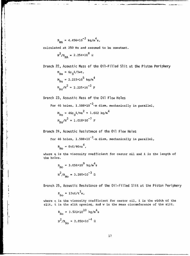
RA = 4.456x10- 2 kg/m4 s,HA
calculated at 250 Hz and assumed to be constant.
2 8N /RHA = 2.254x0 Q
QA
Branch 22, Acoustic Mass of the Oil-Filled Slit at the Piston Periphery
M = 6P £/5wt,so 0
Mso = 2.233xi05 kg/m4
2 -2M /N 2.225xi0 FSo
Branch 23, Acoustic Mass of the Oil Flow Holes
-3For 46 holes, 1.588xlO- .m diam, mechanically in parallel,
2 4M 46p 0£/a = 1.022 kg/Ho 0
2 -7: M /N = l.018xlO FHo
Branch 24, Acoustic Resistance of the Oil Flow Holes
-3_For 46 holes, 1.588xlO --m diam, mechanically in parallel,
R 0 = 8n£/46na4Ho
where n is the viscosity coefficient for castor oil and k is the length ofthe holes.
RHo = 3.056xi09 kg/m4 s
N2/RHo = 3.285xi0- 3
Branch 25, Acoustic Resistance of the Oil-Filled Slit at the Piston Periphery
3RSo = l2n/t w,
where n is the viscosity coefficient for castor oil, Z is the width of theslit, t is the slit opening, and w is the mean circumference of the slit.
R = 3.523x10 kg/m4 sso
2 -4N /Rs = 2.850xi0 -4
17

Branch 26, Radiation Resistance, Piston Radiation
2 8 4RR2 = P0c/ia = 1.829x10 kg/m s
2 -2N /RR2 = 5.489xi0 -
Branch 27, "Radiation Compliance," Piston Radiation
3 _-14 5CRI 0.544a /p0c = 3.123x0
- m /N
2 -7N /CRl = 3.135x10 - H
Branch 28, Radiation Resistance, Piston Radiation
R 9.219x1o 7 kg/m4sR
N N2/R RI : 0.109 Q
I.
Branch 29, Radiation Mass, Piston Radiation
MR = 0.1952pO/a = 3.700xi03 kg/m4
2 -4M /N = 3.686xi0 FR
Branch 30, Acoustic Mass of the Diaphragm
This is measured statically and from "added mass" technique in whichthe shift in the frequency of mechanical resonance caused by a known massis used to determine the unknown mass.
2 2Md = M/(ra
where M is the measured mass.m
Md = 1.375xi03 kg/m4
2 -4M dIN = 1.370x10 F
Branch 31, Mechanical Resistance of Diaphragm Suspension and Guide Bushing
The electrical equivalent is derived from motional impedance of magnet-diaphragm assembly measured in a vacuum.
(BZ) 2/R 73 Q
18

Branch 32, Mechanical Compliance of Suspension-Seal Assembly
Actual value used is the combination of suspension-seal assembly and
oil-filled front piston cavity compliances. Electrical equivalent isderived from measured motion impedance.
2(BX) C = 0.619 H
1
V
'19