a web application for design and sign system using …
TRANSCRIPT

A WEB APPLICATION FOR DESIGN AND SIGN SYSTEM USING ASP.NET
A Paper
Submitted to the Graduate Faculty
of the
North Dakota State University
of Agriculture and Applied Science
By
Sri Lalitha Nuthulapati
In Partial Fulfillment of the Requirements
for the Degree of
MASTER OF SCIENCE
Major Program:
Software Engineering
May 2016
Fargo, North Dakota

North Dakota State University
Graduate School
Title
A WEB APPLICATION FOR DESIGN AND SIGN SYSTEM USING ASP.NET
By
SRI LALITHA NUTHULAPATI
The Supervisory Committee certifies that this disquisition complies with North Dakota
State University’s regulations and meets the accepted standards for the degree of
MASTER OF SCIENCE
SUPERVISORY COMMITTEE:
Dr. Kendall Nygard
Chair
Dr. Kenneth Magel
Dr. Limin Zhang
Approved:
8/3/16 Dr. Kendall Nygard
Date Department Chair

iii
ABSTRACT
Design and Sign System is a web application which aims to improvise the user interface,
work management along with existing database of a legacy application that allows administration
team to maintain day-to-day activities of graphic services. Proposed solution is implemented using
ASP.Net as front end and SQL Server for data management. The entire project is categorized into
four modules.
Project Module allow team to create new/ modify existing project(s) with required
information. Resource Module provides the information on resources availability. Designer
Module has the ability to create, modify and delete designers. Reports Module provides the ability
to track down the reports such as capacity and resource utilization.
In closure, project goal is to provide the team of graphic services with a better user friendly
interface and navigations allowing them to maintain and carry out their day-to-day activities in an
easiest way without much effort.

iv
ACKNOWLEDGEMENTS
The successful completion of any task would be incomplete without mentioning the people
who made it possible, with continuous guidance and encouragement crowns all the efforts with
success.
My Sincere thanks to Dr. Kendall Nygard, for being my advisor and continuous support
throughout my Master’s degree. Thanks to Mr. Nathan Green for providing me an opportunity to
carry out the project work.
Thanks to Stephanie, Carole Huber, and Annette Sprague for their support and service
during my academic period at NDSU.
Very special thanks to the departments TRIO, CCAST, Student Government, NDSA,
General Education Committee, Computer Science Department, and TLMC for providing me an
opportunity to work in different roles at NDSU.
Albeit the title “Acknowledgement” cannot represent my true feelings, I feel very much
thankful to my Mother, Grand Parents, Brother, NDSU and to all the people who helped me in
making this endeavor a reality.
.

v
TABLE OF CONTENTS
ABSTRACT ................................................................................................................................... iii
ACKNOWLEDGMENTS ............................................................................................................ iv
LIST OF TABLES ....................................................................................................................... viii
LIST OF FIGURES ...................................................................................................................... ix
LIST OF ABBREVIATIONS ........................................................................................................ x
CHAPTER 1. INTRODUCTION ................................................................................................... 1
1.1. Project Aims and Objectives ................................................................................... 2
1.2. Background of Project ............................................................................................ 2
1.3. Operation Environment ........................................................................................... 3
CHAPTER 2. SYSTEM ANALYSIS ............................................................................................. 4
2.1. Software Requirement Specification ........................................................................... 4
2.1.1. General Description ...................................................................................... 4
2.1.2. Problem Statement ........................................................................................ 4
2.1.3. System Objectives ......................................................................................... 5
2.1.4. Non Functional Requirements ...................................................................... 5
2.1.5. Functional Requirements .............................................................................. 6
2.1.5.1. Login .............................................................................................. 6
2.1.5.2. Add Project .................................................................................... 6
2.1.5.3. All Projects..................................................................................... 6
2.1.5.4. Add Designer ................................................................................. 7
2.1.5.5. All Designers ................................................................................. 7
2.1.5.6. Add Resource ................................................................................. 7
2.1.5.7. All Resources ................................................................................. 7
2.1.5.8. Reports ........................................................................................... 8

vi
2.1.6. Software Requirements ................................................................................. 8
2.1.7. Hardware Requirements................................................................................ 8
2.2. Legacy vs Proposed ..................................................................................................... 9
2.3. Software Tools Used .................................................................................................... 9
2.3.1. Front End ...................................................................................................... 9
2.3.2. Back End ..................................................................................................... 12
CHAPTER 3. SYSTEM DESIGN ................................................................................................ 13
3.1. Database Design......................................................................................................... 13
3.1.1. Designer Table Design ................................................................................ 13
3.1.2. Resources Table Design .............................................................................. 13
3.1.3. Project Table Design ................................................................................... 14
3.1.4. Used Resources Table Design .................................................................... 14
3.2. UML Diagrams .......................................................................................................... 15
3.2.1. Use Case Diagram for Design and Sign System ......................................... 15
3.2.2. Class Diagram for Design and Sign System ............................................... 16
3.2.3. Sequence Diagram for Design and Sign System ........................................ 17
CHAPTER 4. SYSTEM IMPLEMENTATION ........................................................................... 18
4.1. Module Description ................................................................................................... 19
4.1.1. Admin Module ............................................................................................ 19
4.2. Output Screens ........................................................................................................... 20
4.2.1. Login Screen .............................................................................................. 20
4.2.2. Add Project ................................................................................................. 21
4.2.3. All Projects.................................................................................................. 21
4.2.4. Add Designer .............................................................................................. 22
4.2.5. All Designers .............................................................................................. 22

vii
4.2.6. Add Resource .............................................................................................. 23
4.2.7. All Resources .............................................................................................. 23
4.2.8. Resource Utilization.................................................................................... 24
4.2.9. Capacity Utilization .................................................................................... 24
CHAPTER 5. SYSTEM TESTING .............................................................................................. 25
5.1. Unit Testing ............................................................................................................... 25
5.1.1. Test for Admin/Users Login Form ............................................................. 25
5.1.2. Test for Project Module .............................................................................. 25
5.1.3. Test for Designer Module ........................................................................... 26
5.1.4. Test for Resources Module ......................................................................... 26
5.1.5. Test for Reports Module ............................................................................. 27
5.2. Integration Testing ..................................................................................................... 27
CHAPTER 6. CONCLUSION...................................................................................................... 28
6.1. Conclusion ................................................................................................................. 28
6.2. Future Scope .............................................................................................................. 28
REFERENCES ............................................................................................................................. 29
APPENDIX A.SAMPLE CODE .................................................................................................. 32
A.1. Code for Project Module ........................................................................................... 32
A.2. Code for Designer Module ........................................................................................ 41
A.3. Code for Resource Module ....................................................................................... 48

viii
LIST OF TABLES
Table Page
1. Operation Environment for the Design and Sign System.…………………….…………..3
2. Comparison of Legacy System vs Proposed System..………………………………….....9
3. Schema for Designer Table………………………………………………………………13
4. Schema for Resources Table ….…………………………………………………………13
5. Schema for Project Table.………………………………………………………………..14
6. Schema for Used Resources Table……………………………………………................14

ix
LIST OF FIGURES
Figure Page
1. Use Case Diagram for Design and Sign System ………………………..……………….15
2. Class Diagram for Design and Sign System …...……………………..………...……….16
3. Sequence Diagram for Design and Sign System….……………………..………………17
4. Admin Module for Design and Sign System ….…………………………..…………….19
5. Login Page …….…………………………………………………..…………………….20
6. Successful Login Page …...…..…………………………………………….....................20
7. New Project Page …………………………….……………………………………….....21
8. List of All Projects ………..………..……………………………………..…………..…21
9. New Designer Page …...………………………..…………………….………………….22
10. List of Designers ……………………………...…..…..…………………………………22
11. New Resource Page ………………………….…………………………….……………23
12. List of All Resources ………………………………………………….………………...23
13. Resources Availability Report …………………………………….…….…………..…..24
14. Capacity Utilization Report …………………………………….……………………….24

x
LIST OF ABBREVIATIONS
OS ......................................................Operating System
UI .......................................................User Interface
SRS ....................................................Software Requirement Specification
HTML ................................................Hyper Text Markup Language
CSS ....................................................Cascading Style Sheet
JS ........................................................Java Script
UML ...................................................Unified Modeling Language
ANSI ..................................................American National Standards Institute
SQL ....................................................Structured Query Language

1
CHAPTER 1. INTRODUCTION
Design and Sign System, is a web application, that is developed for the Graphics & Services
Department to maintain the day to day activities, used to track resources and projects ordered.
Graphics & Services provides the poster print services as per the customer needs. The legacy
application that is currently being used by the department is not easy to maintain and project data
is captured with necessary and unnecessary fields on the screen and very difficult to track the
resources that are available and used from the inventory management system. The legacy
application is developed in Classic ASP and data is stored in MS Access.
The Design and Sign System is a proposed application, that is usually tied up with a
relational database to manage the data captured via user interface. Front end of the application is
developed using ASP.NET Web Forms. The entire functionality of the system is analyzed and
divided into modules and each of them is integrated with a unified interface. The modules in the
project are classified as follows:
Project – Creating the projects that are ordered by the customer as unique project, which
captures all the necessary information needed to print the poster as requested.
Resource – The resources that are managed in the inventory can be captured using the
resource screen and can track the list of available vs used, that helps the store recorder to order the
resources when needed.
Designer – Has the ability to add or modify or delete the users of the system and can assign
roles to access the system.
Reports – Tracks the resources availability vs resources used from the inventory
management system.

2
This chapter gives an overview about the aim, objectives, background and operation
environment of the system.
1.1. Project Aims & Objectives
The project aims and objectives will be accomplished after completion of this project is
discussed in below subchapters:
UI re-design with user friendly interface and easy navigations
Upgrade Database from MS Access to SQL Server 2014
Create easy and better UI Navigation for end users
Project Module
Designer Module
Resources Module
Reports Module – Generate reports to track down the work progress
1.2. Background of Project
Design and Sign is a web application which refers to graphic services work management. It
is used by the graphic services team to manage the projects received from students using a
computerized system where he/ she can record various project related information like create,
modify projects, resources and designers.
Project Module helps the administrator to collect the information about the project from the
student which would allow them track/ assign the number of projects using the application along
with providing detailed description about projects. With the help of Design and Sign application, it
is easy to track the status of various projects at any given instinct.
Design Module allows users to add the new designers and has the ability to assign the
designer a role such as User, Guest and Administrator and allow them to access the system. In other

3
words, the system has restricted the designer to access the system based on roles. For example,
Admin designer such as Manager, Primary Admin has access to all the screens in the system.
Resource Module tracks down the inventory availability information such as quantity, cost
and so on. In addition, report module is also included in Design and Sign System. If end user of the
system is admin/ manager, the user is able to generate different kinds of reports like lists of
productivity reports, capacity and resource utilization reports.
All these modules help the end-users of the system to manage system with more efficient
and accessible way as compared to the legacy application.
1.3. Operation Environment
Table 1. Operation Environment for the Design and Sign System
PROCESSOR
Intel Core Processor
OPERATING SYSTEM
WINDOWS7 Or Higher
MEMORY
1GB RAM Or More
HARD DISK SPACE
Minimum 30 GB for Database Usage for future
DATABASE
SQL Server 2014
TECHNICAL SKILLS JavaScript, CSS, HTML, ASP.NET
IDE Visual Studio 2013
WEB SERVER IIS 7.0
4
CHAPTER 2. SYSTEM ANALYSIS
In this chapter, we will discuss and analyze the development process of Design and Sign
System including software requirement specification (SRS) and comparison between legacy and
proposed system. The functional and non-functional requirements are included in SRS that provides
complete description and overview of system requirement before the development is carried out.
Besides that, legacy vs proposed provides a view of how the proposed system will be more efficient
than the legacy one.
2.1. Software Requirement Specification
2.1.1. General Description
Design and Sign System is a web application system which helps end-user to manage the
department daily activity in electronic format that diminishes some of the risks such as improvement
in the screen with necessary fields, enhanced UI and screen navigation. It can help end user
accessing the system to manage the graphic projects more effectively and time-saving.
2.1.2. Problem Statement
Below is the list of problems with legacy application: The application is developed using
classic ASP using MS Access which is very poor in design and performance. The legacy application
is not easily manageable to maintain day-to-day activities of the project.
Difficult to track project status – When there is no proper data capture and validation of the
system, there exists a difficulty in searching for records, if the graphic projects are large in
number(s).
Unused fields – Unused fields in the screens consumes more space and ambiguity for the
end user to provide the input in fields listed on form.

5
Poor Performance – Access to data access for various projects is slow and the UI design is
poor which create more complexity to end-user.
Cost consuming – Due to poor performance, sometimes the work is managed using paper
which will increase the cost as well as re-work to input the information in design and sign system.
2.1.3. System Objectives
Improvement in UI and performance - The system is established to handle with the current
issues and problems of design and sign system. The system has the ability to add project, resource,
designers and user inputs are validated at any given scenario.
Save cost – With the proposed system, the data is maintained in a centralized database to
access the project status.
Save time – End user of the system is able to search/ edit project by using few clicks of
mouse and few search options within stipulated time.
Reports – Admin users able to track and manage the work.
2.1.4. Non Functional Requirements
Efficiency Requirement - When a design and sign system will be implemented the end user
will easily access the projects such as searching, designer’s management and resource tracking will
be become easier.
Reliability Requirement - The system should accurately perform creation, modification,
deletion of a project, input validation, report generation, cost calculation and project status.
Usability Requirement - The system is designed in a user friendly environment, so staff of
graphics department can perform various tasks easily.
Implementation Requirements – On Implementation, the entire system uses ASP.Net,
HTML, CSS, JavaScript in front end and the backend is maintained using SQL Server.

6
2.1.5. Functional Requirements
2.1.5.1 Login
The login screen allows the user to login into system. It is required to enter userid and
password before the user(s) is allowed to enter the system. The userid and password credentials are
validated against the database and access is provided to system assuming credentials are valid.
Otherwise invalid credentials do not provide system access to the user.
2.1.5.2. Add Project
This screen allows the user to add the projects in system.
System must be able to validate the user inputs for corresponding fields
Mandatory fields like Project type, project description are provided to create a
project
System must be able to allow resource addition while creating a project
Duplicate order feature allows the project to create with existing information with
unique id.
2.1.5.3. All Projects
This screen lists all the projects that are added to the system.
Display all the projects that are entered in the system.
Display the list of columns such as Project ID, Project, Customer Name, Assigned
To, Status, and Next Due Date of the project information.

7
2.1.5.4. Add Designer
This screen allows user to add designers to the system. Designers are the users who interact
with the system such as users, guests and administrator.
System must be able to validate the user inputs for the corresponding fields
Access level of the user is assigned while adding the new user to the system by the
administrator.
2.1.5.5. All Designers
This screens display all the designers irrespective of their roles assigned in the system.
System must be able to allow the administrator to change the access level
Edit feature allows the administrator to change the role of the designer
Delete feature allows the administrator to delete the designer from the system
2.1.5.6. Add Resource
This screen allows user to track down the inventory management by department that are
being used as resources to develop the project.
System must be able to add new resources to the system such as Resource Name,
Cost, and Quantity so on.
System must be able to validate the user inputs for corresponding fields
2.1.5.7. All Resources
This screen displays all resources with required information in the system.
System must be able to allow the administrator to perform edit/delete action
Edit feature allows administrator to modify the resource related information
Delete feature allows administrator to delete the resource from the system
8
2.1.5.8. Reports
This screen displays the list of reports that are helpful to track down the work progress by
administrator or manager. System must allow access to reports to the end users of the system such
as administrator or manager but not for others
Resource Availability Report - Displays the resources in a graphical bar representation i.e.
availability vs resources used from the resources table using sql query.
Capacity Utilization Report - Display the work capacity of designers in a graphical bar
representation on projects assigned vs project completed from the project table using sql query.
2.1.6. Software Requirements
Development tools and Programming language- ASP.Net is used to develop the web forms
using C# code and HTML CSS Style Sheets. Java Script is used for input validation.
Operating System - Windows 7 is used as operating system as it is firm and provisions more
features along with user friendly
Database SQL Server - SQL Server 2014 is used as database as it easy to maintain and
retrieve records by simple queries, stored procedures, functions which are flexible to write and
understand.
2.1.7. Hardware Requirements
Intel core i5 is used as a processor as it is fast, reliable and stable to run PC for longtime.
RAM 1 GB is used as it will provide fast writing and reading abilities and in turn support in
processing the applications faster.

9
2.2. Legacy vs Proposed
Table 2. Comparison of Legacy System vs Proposed System
Legacy System
Proposed System
Developed in Classic ASP using MS Access as
database
Developed in ASP.Net Web Application using SQL Server 2014
UI Design of the screens are poor Improved UI design and Navigation of screens in the system
Interaction with the screens in the system are
ambiguous due to unused fields
Unused fields are removed on screens, which makes easy interaction with the system
Doesn’t not have an organized content in the
application.
Organized content on screens with necessary information and divided the entire work into four modules
Doesn’t have a proper structure to track down the
inventory management in the department
Resource module with add/edit/delete actions are provided to track down the inventory
Unable to track down the work and monitor due
to partial data
Data is centralized and able to track down the work progress by using Reports module
2.3. Software Tools Used
The entire project is divided in two parts the front end and the back end. The front end is
designed using of HTML, ASP.NET, CSS, Java script. The back end is designed using SQL Server
which is used to design the databases
2.3.1. Front End
HTML or Hyper Text Markup Language is the main markup language for creating web
pages and additional information also displayed in a web browser that is embedded in ASP.NET
Pages. The Master pages are designed using HTML and are written using the tags enclosed in angle
brackets (like <html>), within the asp.net page content. The headings, images display and the
alignment of menu with box like structure on left hand side of the menu are designed using HTML
tags like <img></img>, <h1></h1>, <block></block>. The first tag in a pair is the start tag, and

10
the second tag is the end tag. The text can be added between the tags to display as required. The
web browser read HTML documents and interpret the tags and displays only the text written
between the tags. Using HTML elements, we have designed a blocks for the module on left side of
the menu. We have inserted the images and objects using HTML to create user friendly forms and
organized the web content in a way that the page has headings, paragraphs, lists, links, quotes and
other items. HTML can also embed the scripts written in languages such as JavaScript to validate
the controls of web pages.
CSS- Cascading Style Sheets is a style sheet language that enhances the User Interface and
formatting of a document written in a markup language. It is primarily focused on document content
presentation in a web page such as the page layout, background, themes, colors, and fonts. This
provide more flexibility, ease of identification of the content on web page and reusability of format
across the website with consistent look, and reduce re-work on design. We have developed the
common styles for heading, bullets, images, layouts and so on and all are documented in a style.css
file, which we can link up the style sheet in any asp.net page across the project. For example, the
class “Heading-1A” is the style that can be applied for the headings on each and every page. We
have defined a custom grid style that suits for our user interface needs.
JavaScript (JS) is a dynamic programming language and prototype-based scripting
language, that allow client-side as well as server-side scripts to interacting with the end user or
system, control the browser, communicate asynchronously, and validate the document content that
is displayed. It is a multi-paradigm language, supporting object-oriented and functional
programming styles. On the client side, JavaScript was traditionally implemented as to validate the
client data before submission of form data to the server, which eventually saves the time and right
data is submitted that meets the specification. For example, we have written a validation using java

11
script to check whether the input given by the user must always be a decimal number for the Project
Cost and it cannot accept characters in the text box control. Using regular expression, we have
validated the text box control to accept only decimals but not any alphabetic or special characters
using java script function.
ASP.NET is a is a development framework that is helpful to build web pages and web sites
with HTML, CSS, JavaScript and server side scripting. ASP.NET is part of the .NET Framework,
and have access to classes in the .NET Framework and can either in visual basic or C#.
The Web Forms framework is very popular and easy to build the web pages and can develop
the web application in rapid application development (RAD) environment by the developers. A web
application can be easily designed by the developers, without having much expertise in HTML,
CSS and JavaScript.
Below are the list of features using Web Forms:
A rich collection of controls for data access and data display
Allows customization as per the needs and can modify the properties and styles of
controls that display on web page
An Event model is handled very well for the web form controls on client side as well
as server side
Automatic protection of data between HTTP requests, which makes it easy for a
programmer to build the client applications for the stateless web.
Web Forms works well for small teams and our project needs because it has the large
number of components available for rapid application development. The components are tightly
integrated and usually require less code than ASP.NET MVC applications. Therefore, Web Forms

12
is not subjected to rapid application development but many complex commercial apps and app
frameworks are built using Web Forms.
2.3.2. Back End
SQL Server is a Microsoft product that is used to manage and store information. It is also
called as Relational Database Management System. SQL stands for Structured Query Language.
According to ANSI (American National Standards Institute), it is the standard language for
relational database management systems. A Database is a logical object that has a collective
organized information that can be easily accessed, managed and updated. The data is stored in the
form of rows and columns called Tables.
SQL statements are used to perform tasks such as update data on a database, or retrieve data
from a database. The standard SQL commands such as "Select", "Insert", "Update", "Delete",
"Create", and "Drop" are used to query against the database.
SQL Server 2014 is a powerful and reliable free data management system which delivers a
rich and reliable data store for lightweight web sites and desktop applications.

13
CHAPTER 3. SYSTEM DESIGN
3.1. Database Design
Below are the tables designed in database to maintain the application information.
3.1.1. Designer Table Design
Table 3. Schema for Designer Table
3.1.2. Resources Table Design
Table 4. Schema for Resources Table
Field Data type Default Key Properties
DesignerID Int Not Null Primary Key Identity(1,1)
UserName Varchar(300) Null
Password Varchar(100) Null
Name Varchar(400) Null
AccessLevel Varchar(100) Null
Field Data type Default Key Properties
MaterialID Int Not Null Primary Key Identity(1,1)
Name Varchar(500) Not Null
Description Varchar(700) Not Null
Location Varchar(100) Null
Quantity Int Null
Manufacturer Varchar(500) Null
PartNumber Varchar(100) Null
Notes Varchar(600) Null
Cost Decimal(18,2) Not Null
TotalCost Decimal(18,2) Not Null
14
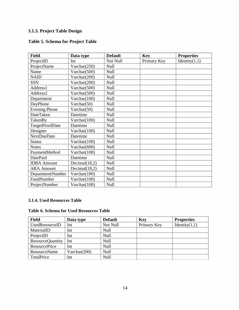
3.1.3. Project Table Design
Table 5. Schema for Project Table
3.1.4. Used Resources Table
Table 6. Schema for Used Resources Table
Field Data type Default Key Properties
ProjectID Int Not Null Primary Key Identity(1,1)
ProjectName Varchar(250) Null
Name Varchar(500) Null
NAID Varchar(200) Null
SSN Varchar(200) Null
Address1 Varchar(500) Null
Address2 Varchar(500) Null
Department Varchar(100) Null
DayPhone Varchar(50) Null
Evening Phone Varchar(50) Null
DateTaken Datetime Null
TakenBy Varchar(100) Null
TargetProofDate Datetime Null
Designer Varchar(100) Null
NextDueDate Datetime Null
Status Varchar(100) Null
Notes Varchar(600) Null
PaymentMethod Varchar(100) Null
DatePaid Datetime Null
IDBA Amount Decimal(18,2) Null
ARA Amount Decimal(18,2) Null
DepartmentNumber Varchar(100) Null
FundNumber Varchar(100) Null
ProjectNumber Varchar(100) Null
Field Data type Default Key Properties
UsedResourceID Int Not Null Primary Key Identity(1,1)
MaterialID Int Null
ProjectID Int Null
ResourceQuantity Int Null
ResourcePrice Int Null
ResourceName Varchar(200) Null
TotalPrice Int Null
15
3.2. UML Diagrams
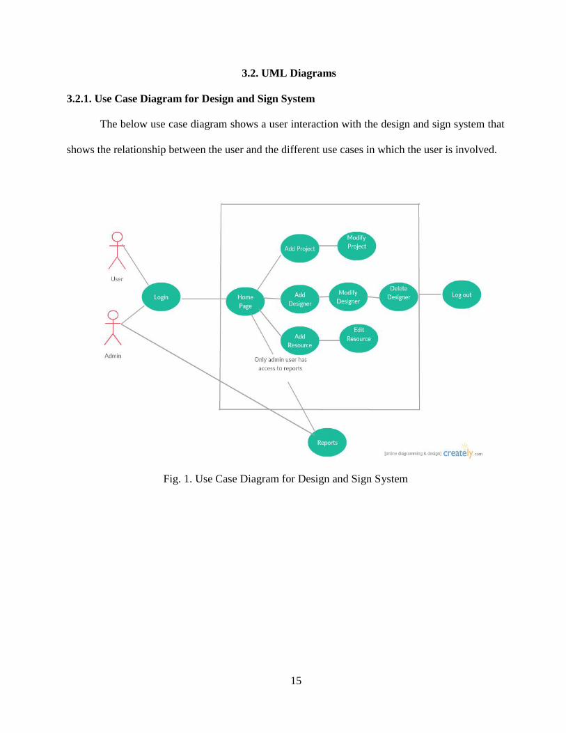
3.2.1. Use Case Diagram for Design and Sign System
The below use case diagram shows a user interaction with the design and sign system that
shows the relationship between the user and the different use cases in which the user is involved.
Fig. 1. Use Case Diagram for Design and Sign System

16
3.2.2. Class Diagram for Design and Sign System
The below class diagram shows the structure of a design and sign system, system’s classes
their attributes, operations and the relationship among objects.
Fig. 2. Class Diagram for Design and Sign System

17
3.2.3. Sequence Diagram for Design and Sign System
The below sequence diagrams shows the flow of logic with in a design and sign system
Fig. 3. Sequence Diagram for Design and Sign System

18
CHAPTER 4. SYSTEM IMPLEMENTATION
To achieve the goals and acceptance from a customer, we followed a standard methodology
called incremental build model to implement the system. The incremental build model is a method
of software development where the application is categorized into modules and a small component
of the module functionality is implemented where the functionality is designed, implemented and
tested incrementally until the module is finished and satisfies all the requirements. This model
combines the elements of the waterfall model with the iterative philosophy of prototyping.
The application work is categorized into modules, each of which is designed and built
separately. Each functionality is delivered to the client when it is completed. This allows us to track
down the behavior of the functionality that meets the customer expectations or not and avoids the
long development time.
The release to customer is referred as “increments”, in each increment we have provided
more functionality in the module to the customers. After the first increment, the module is ready
for the customer with small functionality implementation.
Based on customer acceptance rate on the functionality tested and feedback was taken from
the customer, a plan is developed for the next increments, and changes are made accordingly and
communicated to the development team as well as the client to track the implementation progress.
This process continues, with increments being delivered until all the modules are successfully
delivered.
After each iteration, regression testing is conducted because to identify the bugs before we
delivered the application to the customer and it saves time and cost of the project.

19
4.1. Module Description
The legacy application has carried out all the tasks in the form of hyperlinks provided in the
home page without any organized manner which is not easy to use by the end users of the system.
In order to overcome that, we have categorized the entire tasks into three modules and provided an
extra module called “Reports” to track the down the resources and project status.
In project module, we grouped all the tasks related to the project such as new project, current
projects, all projects, closed projects.
In Designer module, we grouped all the tasks such as new designer, active designers, all
designers and has provided the features such as modify/delete the designers.
In Resource module, we grouped the tasks on resource inventory management such as
addition, modification, deletion of resources and listed all resources.
In Reports module, all the reports related to the project are grouped here.
4.1.1. Admin Module
Fig. 4. Admin Module for Design and Sign System
The above modules contain various features like add/modify/deletion of project, designer,
resources and report generation.
Login
Project Designer Resource Reports
20
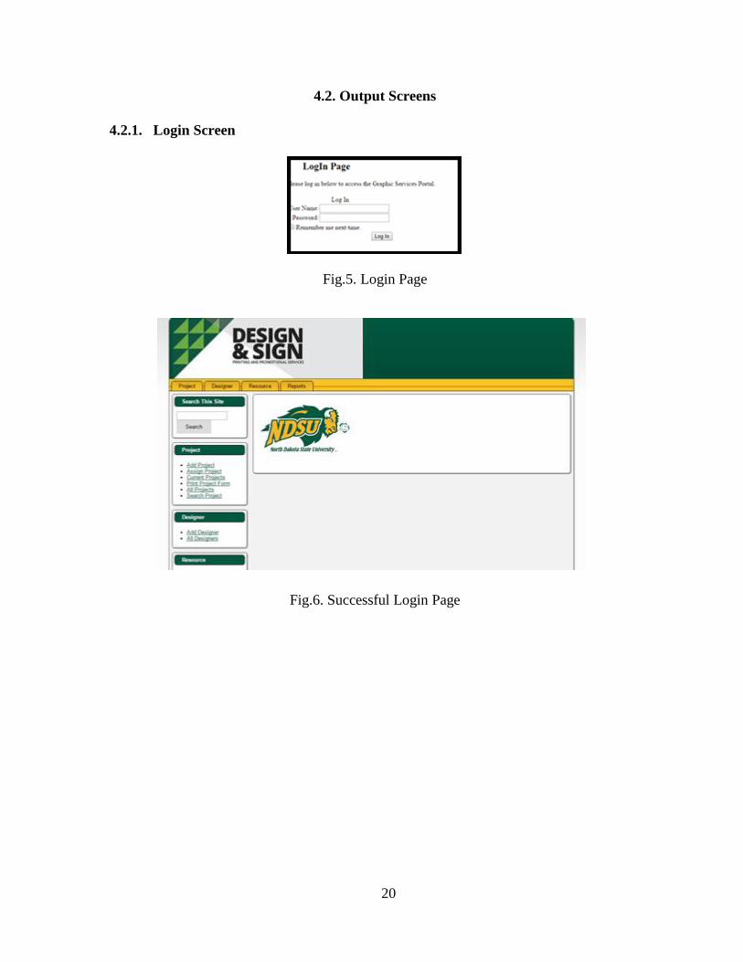
4.2. Output Screens
4.2.1. Login Screen
Fig.5. Login Page
Fig.6. Successful Login Page

21
4.2.2. Add Project
Fig.7. New Project Page
4.2.3. All Projects
Fig.8. List of All Projects

22
4.2.4. Add Designer
Fig.9. New Designer Page
4.2.5. All Designers
Fig.10. List of Designers

23
4.2.6. Add Resource
Fig.11. New Resource Page
4.2.7. All Resources
Fig.12. List of All Resources

24
4.2.8. Resources Utilization
Fig.13. Resources Availability Report
4.2.9. Capacity Utilization
Fig.14. Capacity Utilization Report
25
CHAPTER 5. SYSTEM TESTING
The goal of system testing is to test the whole system in the context of software requirements
specification. It tests the design, behavior of the functionality, out of scope test scenarios as well as
the believed minimum expectations of the customer. Entire project went through two levels of
testing: Unit Testing and Integration Testing.
5.1. Unit Testing
Unit testing will take place within the build phase of the project. After building each
component to meet design specification, the developer is responsible for development of component
and will conduct testing of his/ her own tasks based on design document to confirm that it functions
properly as an individual unit. Unit testing was conducted on each and every module.
5.1.1. Test for Admin/Users Login Form
Login form allows to login users with two type of roles i.e. Admin or Users. We input the
username, password and role of the user if validated as correct input then user able to successfully
login to the system with default page. Otherwise, redirected back to the login page and shown an
error message on the screen that provided credentials are invalid and re-enter again.
5.1.2. Test for Project Module
In this module, the admin can add project details by providing the all mandatory input fields
with required validations and then details are added to the database successfully. Otherwise, the
project form shows the error message on the screen if the required input field values are not
validated properly and cannot submit the data.
It also contains modify and delete buttons if user click on edit button, data will be modified
to the specific project database and if the admin clicks on delete button the specific project data will
be deleted.

26
5.1.3. Test for Designer Module
In this module, the admin can add new designer by providing the all mandatory input fields
with required validations and then details are added to the database successfully. Otherwise, the
designer form shows the error message on the screen if the required input field values are not
validated properly and designer cannot access the system.
It also contains modify and delete buttons if user click on modify button, the designer role
can be updated successfully in the database and if the admin clicks on delete button the specific
designer data will be deleted and cannot access the system.
5.1.4. Test for Resource Module
In this module, the admin can add new resource to the system and has the ability to track
the list of available resources, by providing the all mandatory input fields with required validations
and then resource details are added to the database successfully. Otherwise, the resource form shows
the error message on the screen if the required input field values are not validated properly and
resource cannot be added to the database.
Resource form has the ability to calculate automatically the total cost of all the specific
resources by providing each resource cost.
It also contains modify and delete buttons if user click on modify button, the resource can
be updated successfully in the database and if the admin clicks on delete button the specific resource
data will be deleted from the database.

27
5.1.5. Test for Reports Module
Resource/Capacity Utilization – Reports like resource/capacity utilization displays the list
of resources in a graphical bar representation, as part of testing, we have to test the graph showing
the actual numbers on resources availability vs resources used. This can be validated with the
backend data using sql queries.
5.2. Integration Testing
Integration testing is also referred as String testing which is one of the phases in software
testing. The primary objective of String test is to ensure the software modules/ components function
as per business rule interacted very well with related functions of the screens when combined
together because output regenerated from one module can be considered as an input for other
modules ensuring end-to-end functional flow works according to business requirement. In addition,
it also ensures data sharing between multiple inter connected components/ modules through
Synchronous and Asynchronous are meet the customer requirements. In closure, the integration
testing is carried out after unit testing.
28
CHAPTER 6. CONCLUSION
6.1. Conclusion
This web application provides an improvised version of design and sign system in terms of
user interface, database upgrade as well as the organized content on screens that capture necessary
information, which will benefit the end users of the system.
It makes entire work easy to use and navigate through the screens where the end users can
perform actions such as create, modify and delete the modules named projects, designers and
resources. Also, it can generate reports to track the project status as well as work progress.
6.2. Future Work
There is a scope for future work in the proposed system such as Login authentication for
all the students can be provided as well as validated using NDSU Students Active Directory via
LDAP Connection, which makes entire system online that meets student needs/requests in the
best way possible to create projects as well as to track project status.
29
REFERENCES
[1] "Systems analysis," in Wikipedia, Wikimedia Foundation, 2016. [Online]. Available:
https://en.wikipedia.org/wiki/Systems_analysis. Accessed: Jun. 15, 2016.
[2] "Systems design," in Wikipedia, Wikimedia Foundation, 2016. [Online]. Available:
https://en.wikipedia.org/wiki/Systems_design. Accessed: Jun. 15, 2016.
[3] "Software requirements specification," in Wikipedia, Wikimedia Foundation, 2016.
[Online]. Available: https://en.wikipedia.org/wiki/Software_requirements_specification.
Accessed: Jun. 15, 2016.
[4] "Functional requirement," in Wikipedia, Wikimedia Foundation, 2016. [Online]. Available:
https://en.wikipedia.org/wiki/Functional_requirement. Accessed: Jun. 15, 2016.
[5] "Non-functional requirement," in Wikipedia, Wikimedia Foundation, 2016. [Online].
Available: https://en.wikipedia.org/wiki/Non-functional_requirement. Accessed: Jun. 15,
2016.
[6] "Use case diagram," in Wikipedia, Wikimedia Foundation, 2016. [Online]. Available:
https://en.wikipedia.org/wiki/Use_Case_Diagram. Accessed: Jun. 15, 2016.
[7] "User story," in Wikipedia, Wikimedia Foundation, 2016. [Online]. Available:
https://en.wikipedia.org/wiki/User_story. Accessed: Jun. 15, 2016.
[8] "Unified modeling language," in Wikipedia, Wikimedia Foundation, 2016. [Online].
Available: https://en.wikipedia.org/wiki/Unified_Modeling_Language. Accessed: Jun. 15,
2016.
[9] "UML 2 class diagrams: An agile introduction," 2004. [Online]. Available:
http://agilemodeling.com/artifacts/classDiagram.htm. Accessed: Jun. 15, 2016.

30
[10] "Sequence diagram," in Wikipedia, Wikimedia Foundation, 2016. [Online]. Available:
https://en.wikipedia.org/wiki/Sequence_diagram. Accessed: Jun. 15, 2016.
[11] "Activity diagram," in Wikipedia, Wikimedia Foundation, 2016. [Online]. Available:
https://en.wikipedia.org/wiki/Activity_diagram. Accessed: Jun. 15, 2016.
[12] "Integration testing," in Wikipedia, Wikimedia Foundation, 2016. [Online]. Available:
https://en.wikipedia.org/wiki/Integration_testing. Accessed: Jun. 15, 2016.
[13] "Unit testing," in Wikipedia, Wikimedia Foundation, 2016. [Online]. Available:
https://en.wikipedia.org/wiki/Unit_testing. Accessed: Jun. 15, 2016.
[14] "Software development methodologies," 2016. [Online]. Available:
http://www.itinfo.am/eng/software-development-methodologies/. Accessed: Jun. 15, 2016.
[15] "Incremental build model," in Wikipedia, Wikimedia Foundation, 2016. [Online]. Available:
https://en.wikipedia.org/wiki/Incremental_build_model. Accessed: Jun. 15, 2016.
[16] "SDLC - Iterative model," in www.tutorialspoint.com, www.tutorialspoint.com, 2016.
[Online]. Available: http://www.tutorialspoint.com/sdlc/sdlc_iterative_model.htm.
Accessed: Jun. 15, 2016.
[17] "CSS backgrounds," in www.w3schools.com. [Online]. Available:
http://www.w3schools.com/css/css_background.asp. Accessed: Jun. 15, 2016.
[18] I. Sommerville, Software engineering >INTERNATIONAL EDITION <, 9th ed. Harlow:
Pearson Education (US), 2010.
[19] "Incremental build model," in Wikipedia, Wikimedia Foundation, 2016. [Online]. Available:
https://en.wikipedia.org/wiki/Incremental_build_model. Accessed: Jun. 15, 2016.
[20] Microsoft, "ASP.NET overview," 2016. [Online]. Available: https://msdn.microsoft.com/en-
us/library/4w3ex9c2.aspx. Accessed: Jun. 15, 2016.

31
[21] "ASP.NET," in Wikipedia, Wikimedia Foundation, 2016. [Online]. Available:
https://en.wikipedia.org/wiki/ASP.NET. Accessed: Jun. 15, 2016.
[22] "ASP.NET Tutorial," www.tutorialspoint.com, 2016. [Online]. Available:
http://www.tutorialspoint.com/asp.net/. Accessed: Jun. 15, 2016.
[23] "SDLC - Iterative model," www.tutorialspoint.com, 2016. [Online]. Available:
http://www.tutorialspoint.com/sdlc/sdlc_iterative_model.htm. Accessed: Jun. 15, 2016.
[24] "Software development methodologies," 2016. [Online]. Available:
http://www.itinfo.am/eng/software-development-methodologies/. Accessed: Jun. 15, 2016.
[25] "SQL INSERT INTO statement,". [Online]. Available:
http://www.w3schools.com/sql/sql_insert.asp. Accessed: Jun. 15, 2016.
[26] "Introduction to HTML,". [Online]. Available:
http://www.w3schools.com/html/html_intro.asp. Accessed: Jun. 15, 2016.
[27] "JavaScript data,". [Online]. Available: http://www.w3schools.com/js/js_datatypes.asp.
Accessed: Jun. 15, 2016.
[28] "CSS backgrounds,". [Online]. Available:
http://www.w3schools.com/css/css_background.asp. Accessed: Jun. 15, 2016.
[29] "JavaScript data,". [Online]. Available: http://www.w3schools.com/js/js_datatypes.asp.
Accessed: Jun. 15, 2016.
[30] "SQL INSERT INTO statement,". [Online]. Available:
http://www.w3schools.com/sql/sql_insert.asp. Accessed: Jun. 15, 2016.

32
APPENDIX A. SAMPLE CODE
A.1. Code for Project Module
On submit click, the below code helps to create a new project with the required input
fields and validate some of the fields on the project screen and able to successfully store the data
in a database.
<%@ Page Title="" Language="C#" MasterPageFile="~/MasterPage.master" AutoEventWireup="true" CodeBehind="AddProjects.aspx.cs" Inherits="Graphics.Test" %>
<asp:Content ID="Content1" ContentPlaceHolderID="Head" runat="server">
<link rel="stylesheet" href="NDSUButton.css" />
</asp:Content>
<asp:Content ID="Content2" ContentPlaceHolderID="Content" runat="server">
<form id="form1" runat="server">
<link rel="stylesheet" href="NDSUButton.css" />
<h1>New Project</h1>
<div>
<asp:Button ID="btnDuplicate" CssClass="ndsubutton" runat="server" Text="Duplicate Order" />
<table id="tblDept" runat="server">
<tr>
<td>
<asp:Label ID="lblPrjType" runat="server" Text="Project Type *"></asp:Label>
</td>
<td>
<asp:DropDownList ID="ddlPrjType" runat="server" Width="174px">
<asp:ListItem>Department Charge</asp:ListItem>
<asp:ListItem>Personal/Quick Print</asp:ListItem>
<asp:ListItem>Student Org/AR Group</asp:ListItem>
</asp:DropDownList>

33
</td>
</tr>
<tr>
<td>
<asp:Label ID="lblPrjDesc" runat="server" Text="Project Description *"></asp:Label>
</td>
<td>
<asp:TextBox ID="txtPrjDesc" runat="server" Width="174px"></asp:TextBox>
<asp:RequiredFieldValidator ID="RFVPrjName" runat="server" ErrorMessage="Project Name is Required" ControlToValidate="txtPrjDesc"></asp:RequiredFieldValidator><br />
</td>
</tr>
<tr>
<td>
<asp:Label ID="lblCName" runat="server" Text="Customer's Name"></asp:Label>
</td>
<td>
<asp:TextBox ID="txtCName" runat="server" Width="174px"></asp:TextBox>
<asp:RequiredFieldValidator ID="rfvCName" runat="server" ErrorMessage="Project Name is Required" ControlToValidate="txtCName"></asp:RequiredFieldValidator><br />
</td>
</tr>
<tr>
<td>
<asp:Label ID="lblCAddress" runat="server" Text="Campus Address"></asp:Label>
</td>
34
<td>
<asp:TextBox ID="txtCAddress" runat="server" Width="174px"></asp:TextBox><br />
</td>
</tr>
<tr>
<td>
<asp:Label ID="lblDptName" runat="server" Text="Department Name"></asp:Label>
</td>
<td>
<asp:TextBox ID="txtDptName" runat="server" Width="174px"></asp:TextBox>
<asp:RequiredFieldValidator ID="RFVDept" runat="server" ErrorMessage="Department is Required" ControlToValidate="txtDptName"></asp:RequiredFieldValidator><br />
</td>
</tr>
<tr>
<td>
<asp:Label ID="lblDptNo" runat="server" Text="Department Number"></asp:Label>
</td>
<td>
<asp:TextBox ID="txtDptNo" runat="server" Width="174px"></asp:TextBox><br />
</td>
</tr>
<tr>
<td>
<asp:Label ID="lblFund" runat="server" Text="Fund Number"></asp:Label>

35
</td>
<td>
<asp:TextBox ID="txtFund" runat="server" Width="174px"></asp:TextBox><br />
</td>
</tr>
<tr>
<td>
<asp:Label ID="lblCntNo" runat="server" Text="Contact No."></asp:Label>
</td>
<td>
<asp:TextBox ID="txtCntNo" runat="server" Width="174px"></asp:TextBox><br />
</td>
</tr>
<tr>
<td>
<asp:Label ID="lblDateOrdered" runat="server" Text="Date Ordered"></asp:Label>
</td>
<td>
<asp:TextBox ID="txtDateOrdered" runat="server" Width="174px"></asp:TextBox><br />
</td>
</tr>
<tr>
<td>
<asp:Label ID="lblOrderedBy" runat="server" Text="Ordered By"></asp:Label>
</td>

36
<td>
<asp:TextBox ID="txtOrderedBy" runat="server" Width="174px"></asp:TextBox><br />
</td>
</tr>
<tr>
<td>
<asp:Label ID="lblDesigner" runat="server" Text="Designer"></asp:Label>
</td>
<td>
<asp:DropDownList ID="txtDesigner" runat="server" Width="174px">
<asp:ListItem>Nathan Green</asp:ListItem>
<asp:ListItem>Sri Lalitha</asp:ListItem>
<asp:ListItem>Test Admin</asp:ListItem>
</asp:DropDownList>
<br />
</td>
</tr>
<tr>
<td>
<asp:Label ID="lblPStatus" runat="server" Text="Status"></asp:Label>
</td>
<td>
<asp:DropDownList ID="ddlStatus" runat="server" Width="174px">
<asp:ListItem>Paid</asp:ListItem>
<asp:ListItem>No Payment</asp:ListItem>
</asp:DropDownList><br />

37
</td>
</tr>
<tr>
<td>
<asp:Label ID="lblUrgent" runat="server" Text="Urgent"></asp:Label>
</td>
<td>
<asp:DropDownList ID="ddlUrgent" runat="server" Width="174px">
<asp:ListItem>Yes</asp:ListItem>
<asp:ListItem>No</asp:ListItem>
</asp:DropDownList><br />
</td>
</tr>
<tr>
<td>
<asp:Label ID="lblNotes" runat="server" Text="Notes"></asp:Label>
</td>
<td>
<asp:TextBox ID="txtNotes" runat="server" TextMode="MultiLine" Height="57px" Width="174px"></asp:TextBox><br />
</td>
</tr>
<tr>
<td>
<asp:Label ID="lblRes" runat="server" Text="Resources: No Resources used on this project"></asp:Label>
</td>
<td>
38
<asp:HyperLink ID="hlRes" runat="server" Text="Add a resource"></asp:HyperLink>
<br />
</td>
<td></td>
</tr>
<tr>
<td>
<asp:Label ID="lblAmt" runat="server" Text="Total Amount"></asp:Label>
</td>
<td>
<asp:TextBox ID="txtAmt" runat="server" Width="174px"></asp:TextBox><br />
</td>
</tr>
<tr>
<td>
<asp:Button ID="btnSubmit" CssClass="ndsubutton" runat="server" Text="Add Project" OnClick="btnSubmit_Click" /><br />
</td>
</tr>
<tr>
<td>
<asp:Label ID="lblStatus" runat="server" Text="" Visible="false"></asp:Label>
</td>
</tr>
</table>

39
</div>
</form>
</asp:Content>
<asp:Content ID="Content3" ContentPlaceHolderID="Footer" runat="server">
</asp:Content>
<asp:Content ID="Content4" ContentPlaceHolderID="AfterBody" runat="server">
</asp:Content>
using System;
using System.Collections.Generic;
using System.Linq;
using System.Web;
using System.Web.UI;
using System.Web.UI.WebControls;
using System.Data;
using System.Data.SqlClient;
using System.Data.Sql;
using System.Configuration;
namespace Graphics
{
public partial class Test : System.Web.UI.Page
{
protected void Page_Load(object sender, EventArgs e)
{
if (!IsPostBack)
{
}

40
}
protected void btnSubmit_Click(object sender, EventArgs e)
{
string strconn = ConfigurationManager.ConnectionStrings["Conn"].ToString();
SqlConnection conn = new SqlConnection(strconn);
conn.Open();
string query = "InsertProject";
SqlCommand cmd = new SqlCommand(query, conn);
cmd.CommandType = CommandType.StoredProcedure;
SqlDataAdapter adp = new SqlDataAdapter(cmd);
cmd.Parameters.AddWithValue("@ProjectName", txtProjName.Text.ToString());
// cmd.Parameters.AddWithValue("@Name", txtCustName.Text.ToString());
//cmd.Parameters.AddWithValue("@NAID", txtCustNAID.Text.ToString());
// cmd.Parameters.AddWithValue("@SSN", txtCustSSN.Text.ToString());
cmd.Parameters.AddWithValue("@Address1", txtAddr.Text.ToString());
//cmd.Parameters.AddWithValue("@Address2", txtAddr2.Text.ToString());
cmd.Parameters.AddWithValue("@Department", txtDept.Text.ToString());
cmd.Parameters.AddWithValue("@DayPhone", txtDayPhn.Text.ToString());
//cmd.Parameters.AddWithValue("@EveningPhone", txtEvePhn.Text.ToString());
cmd.Parameters.AddWithValue("@DateTaken", DateTime.Now);
//cmd.Parameters.AddWithValue("@TakenBy", txtCustName.Text.ToString());
//cmd.Parameters.AddWithValue("@TargetProofDate", txtProfDate.Text.ToString());
//cmd.Parameters.AddWithValue("@Designer", txtCustName.Text.ToString());
cmd.Parameters.AddWithValue("@NextDueDate", DateTime.Now);
//cmd.Parameters.AddWithValue("@Status", txtCustName.Text.ToString());
cmd.Parameters.AddWithValue("@Notes", txtNotes.Text.ToString());
cmd.Parameters.AddWithValue("@PaymentMethod", ddlPay.SelectedValue.ToString());
41
cmd.Parameters.AddWithValue("@DatePaid", DateTime.Now);
cmd.Parameters.AddWithValue("@IDBAmount", txtFund.Text.ToString());
cmd.Parameters.AddWithValue("@ARAmount", txtFund.Text.ToString());
cmd.Parameters.AddWithValue("@DepartmentNumber", txtDept2.Text.ToString());
cmd.Parameters.AddWithValue("@FundNumber", txtFund.Text.ToString());
//cmd.Parameters.AddWithValue("@ProjectNumber", txtProject.Text.ToString());
cmd.ExecuteNonQuery();
lblStatus.Visible = true;
lblStatus.Text = "New Project Added Successfully";
}
A.2. Code for Designer Module
On click on Add Designer button, the below code helps to create the new designers that use
the system with required input fields and validation.
<%@ Page Title="" Language="C#" MasterPageFile="~/MasterPage.master" AutoEventWireup="true" EnableEventValidation="false" CodeBehind="AllDesigner.aspx.cs" Inherits="Graphics.AllDesigner" %>
<asp:Content ID="Content1" ContentPlaceHolderID="Head" runat="server">
</asp:Content>
<asp:Content ID="Content2" ContentPlaceHolderID="Content" runat="server">
<form id="form1" runat="server">
<link rel="stylesheet" href="style.css" />
<h1>All Designers</h1>
<div>
<asp:GridView ID="gvDesigner" runat="server" AutoGenerateColumns="false"
ShowFooter="true" GridLines="None" CssClass="mGrid" AlternatingRowStyle-CssClass="alt" PagerStyle-CssClass="pgr"
OnRowCommand="gvDesigner_RowCommand"
OnRowDeleting="gvDesigner_RowDeleting"
OnRowUpdating="gvDesigner_RowUpdating"

42
OnRowCancelingEdit="gvDesigner_RowCancelingEdit"
OnRowEditing="gvDesigner_RowEditing" ViewStateMode="Enabled" EnableViewState="true">
<Columns>
<asp:TemplateField HeaderText="ID">
<ItemTemplate>
<asp:Label ID="lblID" runat="server" Text='<%#DataBinder.Eval(Container.DataItem,"DesignerID") %>'></asp:Label>
</ItemTemplate>
<EditItemTemplate>
<asp:Label ID="lblEditID" runat="server" Text='<%#DataBinder.Eval(Container.DataItem, "DesignerID") %>'> </asp:Label>
</EditItemTemplate>
</asp:TemplateField>
<asp:TemplateField HeaderText="Designer Name">
<ItemTemplate>
<asp:Label ID="lblDesigner" runat="server" Text='<%#DataBinder.Eval(Container.DataItem,"Name") %>'></asp:Label>
</ItemTemplate>
<EditItemTemplate>
<asp:TextBox ID="txtEditDesigner" runat="server" Text='<%#DataBinder.Eval(Container.DataItem, "Name") %>'></asp:TextBox>
</EditItemTemplate>
</asp:TemplateField>
<asp:TemplateField HeaderText="User Name">
<ItemTemplate>
<asp:Label ID="lblUserName" runat="server" Text='<%#DataBinder.Eval(Container.DataItem,"UserName") %>'></asp:Label>
</ItemTemplate>
<EditItemTemplate>
43
<asp:TextBox ID="txtEditUserName" runat="server" Text='<%#DataBinder.Eval(Container.DataItem, "UserName") %>'></asp:TextBox>
</EditItemTemplate>
</asp:TemplateField>
<asp:TemplateField HeaderText="Access Level">
<ItemTemplate>
<asp:Label ID="lblALevel" runat="server" Text='<%#DataBinder.Eval(Container.DataItem,"AccessLevel") %>'></asp:Label>
</ItemTemplate>
<EditItemTemplate>
<asp:TextBox ID="txtALevel" runat="server" Text='<%#DataBinder.Eval(Container.DataItem, "AccessLevel") %>'></asp:TextBox>
</EditItemTemplate>
</asp:TemplateField>
<asp:TemplateField HeaderText="Action">
<ItemTemplate>
<asp:ImageButton ID="imgbtnEdit" runat="server" CommandName="Edit" ImageUrl="~/Images/untitled.png" CausesValidation="true" Height="12px" Width="12px" />
<asp:ImageButton ID="imgbtnDelete" runat="server" CommandName="Delete" ImageUrl="~/Images/delete.png" CausesValidation="true" Height="12px" Width="12px" />
</ItemTemplate>
<EditItemTemplate>
<asp:ImageButton ID="imgbtnUpdate" runat="server" CommandName="Update" ImageUrl="~/Images/untitled.png" CausesValidation="true" Height="12px" Width="12px" />
<asp:ImageButton ID="imgbtnCancel" runat="server" CommandName="Cancel" ImageUrl="~/Images/delete.png" CausesValidation="true" Height="12px" Width="12px" />
</EditItemTemplate>
<FooterTemplate>
</FooterTemplate>
</asp:TemplateField>

44
</Columns>
</asp:GridView>
</div>
</form>
</asp:Content>
<asp:Content ID="Content3" ContentPlaceHolderID="Footer" runat="server">
</asp:Content>
<asp:Content ID="Content4" ContentPlaceHolderID="AfterBody" runat="server">
</asp:Content>
using System;
using System.Collections.Generic;
using System.Linq;
using System.Web;
using System.Web.UI;
using System.Web.UI.WebControls;
using System.Data;
using System.Data.Sql;
using System.Data.SqlClient;
using System.Configuration;
namespace Graphics
{
public partial class AllDesigner : System.Web.UI.Page
{
protected void Page_Load(object sender, EventArgs e)
{
if (!IsPostBack)

45
{
LoadData();
}
}
public void LoadData()
{
DataSet ds = new DataSet();
DataTable dt = new DataTable();
string strconn = ConfigurationManager.ConnectionStrings["Conn"].ToString();
SqlConnection conn = new SqlConnection(strconn);
conn.Open();
String query = "select DesignerID,Name,UserName,AccessLevel from Designers";
SqlCommand cmd = new SqlCommand(query, conn);
SqlDataAdapter adp = new SqlDataAdapter(cmd);
adp.Fill(ds);
cmd.ExecuteNonQuery();
dt = ds.Tables[0];
// if (dt.Rows.Count > 0)
//{
gvDesigner.DataSource = dt;
gvDesigner.DataBind();
//}
conn.Close();
}
protected void gvDesigner_RowEditing(object sender, GridViewEditEventArgs e)

46
{
gvDesigner.EditIndex = e.NewEditIndex;
LoadData();
}
protected void gvDesigner_RowUpdating(object sender, GridViewUpdateEventArgs e)
{
string strconn = ConfigurationManager.ConnectionStrings["Conn"].ToString();
SqlConnection conn = new SqlConnection(strconn);
Label lblEditID = (Label)gvDesigner.Rows[e.RowIndex].FindControl("lblEditID");
TextBox txtEditDesigner = (TextBox)gvDesigner.Rows[e.RowIndex].FindControl("txtEditDesigner");
TextBox txtEditUserName = (TextBox)gvDesigner.Rows[e.RowIndex].FindControl("txtEditUserName");
TextBox txtALvl = (TextBox)gvDesigner.Rows[e.RowIndex].FindControl("txtALevel");
conn.Open();
string cmdstr = "update Designers set name=@name,username=@username,accesslevel=@accesslevel where designerid=@designerid";
SqlCommand cmd = new SqlCommand(cmdstr, conn);
cmd.Parameters.AddWithValue("@name", txtEditDesigner.Text);
cmd.Parameters.AddWithValue("@username", txtEditUserName.Text);

47
cmd.Parameters.AddWithValue("@accesslevel", txtALvl.Text);
cmd.Parameters.AddWithValue("@designerid", lblEditID.Text);
cmd.ExecuteNonQuery();
conn.Close();
gvDesigner.EditIndex = -1;
LoadData();
}
protected void gvDesigner_RowCancelingEdit(object sender, GridViewCancelEditEventArgs e)
{
gvDesigner.EditIndex = -1;
LoadData();
}
protected void gvDesigner_RowDeleting(object sender, GridViewDeleteEventArgs e)
{
string strconn = ConfigurationManager.ConnectionStrings["Conn"].ToString();
SqlConnection conn = new SqlConnection(strconn);
conn.Open();
Label lblDesId = (Label)gvDesigner.Rows[e.RowIndex].FindControl("lblID");
string cmdstr = "delete from Designers where DesignerID=@DesignerID";
SqlCommand cmd = new SqlCommand(cmdstr, conn);
cmd.Parameters.AddWithValue("@DesignerID", lblDesId.Text);
cmd.ExecuteNonQuery();
conn.Close();
LoadData();
}))

48
A.3. Code for Resource Module
On click on add resource button, the below code helps to add the resources that are used in
the project with required input fields and validation on the resource screen.
<%@ Page Title="" Language="C#" MasterPageFile="~/MasterPage.master" AutoEventWireup="true" CodeBehind="AddResources.aspx.cs" Inherits="Graphics.AddResources" %>
<asp:Content ID="Content1" ContentPlaceHolderID="Head" runat="server">
</asp:Content>
<asp:Content ID="Content2" ContentPlaceHolderID="Content" runat="server">
<form id="form1" runat="server">
<link rel="stylesheet" href="NDSUButton.css" />
<h1>New Resource</h1>
<script type="text/javascript">
function txtOnKeyPress(txtTotal) {
if (txt1 != 'undefined') {
var txt1 = document.getElementById('<%=txtQty.ClientID%>');
var txt2 = document.getElementById('<%=txtCost.ClientID%>');
var txt3 = txt1 + txt2;
}
}
</script>
<div>
<table>
<tr>
<td>
<asp:Label ID="lblResName" runat="server" Text="Resource Name"></asp:Label>
</td>

49
<td>
<asp:TextBox ID="txtResName" runat="server" Width="174px"></asp:TextBox>
<asp:RequiredFieldValidator ID="RFVResName" runat="server" ErrorMessage="Resource Name is Required" ControlToValidate="txtResName"></asp:RequiredFieldValidator><br />
</td>
</tr>
<tr>
<td>
<asp:Label ID="lblQty" runat="server" Text="Quantity"></asp:Label>
</td>
<td>
<asp:TextBox ID="txtQty" runat="server" Width="174px"></asp:TextBox>
<asp:RequiredFieldValidator ID="RFVQty" runat="server" ErrorMessage="Quantity is Required" ControlToValidate="txtQty"></asp:RequiredFieldValidator><br />
<asp:RegularExpressionValidator ID="RegExQty" runat="server" ValidationExpression="((\d+)+(\.\d+))$"
ErrorMessage="Please enter valid decimal/integer number with any decimal places." ControlToValidate="txtQty" />
</td>
</tr>
<tr>
<td>
<asp:Label ID="lblDes" runat="server" Text="Description"></asp:Label>
</td>
<td>

50
<asp:TextBox ID="txtDes" runat="server" TextMode="MultiLine" Width="174px" Height="60px"></asp:TextBox>
<asp:RequiredFieldValidator ID="RFVDes" runat="server" ErrorMessage="Description is Required" ControlToValidate="txtDes"></asp:RequiredFieldValidator><br />
</td>
</tr>
<tr>
<td>
<asp:Label ID="lblMfr" runat="server" Text="Manufacturer"></asp:Label>
</td>
<td>
<asp:TextBox ID="txtMfr" runat="server" Width="174px"></asp:TextBox><br />
</td>
</tr>
<tr>
<td>
<asp:Label ID="lblPartNum" runat="server" Text="Part Number"></asp:Label>
</td>
<td>
<asp:TextBox ID="txtPartNum" runat="server" Width="174px"></asp:TextBox><br />
</td>
</tr>
<tr>
<td>
<asp:Label ID="lblCost" runat="server" Text="Cost(each)"></asp:Label>
</td>

51
<td>
<asp:ScriptManager ID="ScriptManager2" runat="server">
</asp:ScriptManager>
<asp:UpdatePanel ID="UpdatePanel1" runat="server">
<ContentTemplate>
<asp:TextBox ID="txtCost" runat="server" Width="174px" AutoPostBack="True" OnTextChanged="txtCost_TextChanged"></asp:TextBox>
<br />
<asp:TextBox ID="txtTotal" runat="server" Width="174px" Enabled="false"></asp:TextBox>
<asp:RequiredFieldValidator ID="RFVCost" runat="server" ErrorMessage="Cost is Required" ControlToValidate="txtCost"></asp:RequiredFieldValidator><br />
<asp:RegularExpressionValidator ID="RegCost" runat="server" ValidationExpression="((\d+)+(\.\d+))$"
ErrorMessage="Please enter valid decimal/integer number with any decimal places." ControlToValidate="txtCost" />
</ContentTemplate>
</asp:UpdatePanel>
</td>
</tr>
<tr>
<td>
<asp:Label ID="lblLoc" runat="server" Text="Location"></asp:Label>
</td>
<td>
<asp:TextBox ID="txtLoc" runat="server" Width="174px"></asp:TextBox><br />
</td>
</tr>
<tr>

52
<td>
<asp:Label ID="lblNotes" runat="server" Text="Notes"></asp:Label>
</td>
<td>
<asp:TextBox ID="txtNotes" runat="server" TextMode="MultiLine" Width="174px" Height="60px"></asp:TextBox><br />
</td>
</tr>
<tr>
<td>
<asp:Button ID="btnSubmit" CssClass="ndsubutton" runat="server" Text="Add Resource" OnClick="btnSubmit_Click" />
</td>
</tr>
<tr>
<td>
<asp:Label ID="lblStatus" runat="server" Text="" Visible="false"></asp:Label>
</td>
</tr>
</table>
</div>
</form>
</asp:Content>
<asp:Content ID="Content3" ContentPlaceHolderID="Footer" runat="server">
</asp:Content>
<asp:Content ID="Content4" ContentPlaceHolderID="AfterBody" runat="server">
</asp:Content>

53
using System;
using System.Collections.Generic;
using System.Linq;
using System.Web;
using System.Web.UI;
using System.Web.UI.WebControls;
using System.Data;
using System.Data.SqlClient;
using System.Data.Sql;
using System.Configuration;
using System.Text;
namespace Graphics
{
public partial class AddResources : System.Web.UI.Page
{
protected void Page_Load(object sender, EventArgs e)
{
if(!IsPostBack)
{
}
}
protected void btnSubmit_Click(object sender, EventArgs e)
{
string strconn = ConfigurationManager.ConnectionStrings["Conn"].ToString();
SqlConnection conn = new SqlConnection(strconn);
conn.Open();
string query = "InsertResource";

54
SqlCommand cmd = new SqlCommand(query, conn);
cmd.CommandType = CommandType.StoredProcedure;
SqlDataAdapter adp = new SqlDataAdapter(cmd);
cmd.Parameters.AddWithValue("@Name", txtResName.Text.ToString());
cmd.Parameters.AddWithValue("@Description", txtDes.Text.ToString());
cmd.Parameters.AddWithValue("@Location", txtLoc.Text.ToString());
cmd.Parameters.AddWithValue("@Quantity", Convert.ToDecimal(txtQty.Text));
cmd.Parameters.AddWithValue("@Manufacturer", txtMfr.Text.ToString());
cmd.Parameters.AddWithValue("@PartNumber", txtPartNum.Text.ToString());
cmd.Parameters.AddWithValue("@Notes", txtNotes.Text.ToString());
cmd.Parameters.AddWithValue("@Cost", Convert.ToDecimal(txtCost.Text));
string total = txtTotal.Text;
cmd.Parameters.AddWithValue("@TotalCost", Convert.ToDecimal(total.Substring(6)));
cmd.ExecuteNonQuery();
lblStatus.Visible = true;
lblStatus.Font.Bold = true;
lblStatus.Text = "New Resource Added Successfully";
lblStatus.ForeColor = System.Drawing.Color.Red;
Clear();
}
public void Clear()
{
txtResName.Text = "";
txtQty.Text = "";
txtDes.Text = "";
txtMfr.Text = "";
txtPartNum.Text = "";

55
txtCost.Text = "";
txtTotal.Text = "";
txtLoc.Text = "";
txtNotes.Text = "";
}
protected void txtCost_TextChanged(object sender, EventArgs e)
{
decimal Total = (Convert.ToDecimal(txtCost.Text) * Convert.ToDecimal(txtQty.Text));
txtTotal.Text += "Total:"+ Convert.ToString(Total);
}
}
}