a vk pr 2009 0139 gb mpower geko uk version df 2009-10-150dpi
DESCRIPTION
GEATRANSCRIPT

Air Treatment
GEA MPower - Geko
Fan Coil Units | Data & Facts
Effective use of air distribution and capacity

Table of Contents GEA MPower-Geko Fan Coil Unit
2 PR-2009-0139-GB • Subject to modifications • Status 10/2009
Sizes .......................................................................................................... 1.2
Fan Coil Unit Components ......................................................................... 2
Unit Selection ............................................................................................... 3
Unit Description ........................................................................................... 4
Recirculating Air Unit Cooling and Heating .............................................. 6Accessories/Valves .............................................................................................. 7
Recirculating Air Unit Cooling and Heating .............................................. 8Accessories/Valves .............................................................................................. 9
Recirculating Air Unit Heating .................................................................. 10Accessories/Valves ............................................................................................ 11
Recirculating Air Unit Heating .................................................................. 12Accessories/Valves ............................................................................................ 13
Pressure Drop in Heat Exchanger, Warm and Chilled Water ................ 14
Power and Current Consumption ............................................................. 15
Capacity Overview for Different Operating Points Size 1....................... 16Overview of Acoustic Data for Different Operating Points, Size 1 ...................... 17
Capacity Overview for Different Operating Points Size 2....................... 18Overview of Acoustic Data for Different Operating Points, Size 2 ...................... 19
Capacity Overview for Different Operating Points Size 3....................... 20Overview of Acoustic Data for Different Operating Points, Size 3 ...................... 21
Capacity Overview for Different Operating Points Size 4 ...................... 22Overview of Acoustic Data for Different Operating Points, Size 4 ...................... 23
Samples for Capacity Definition .............................................................. 24
Installation Samples .................................................................................. 28
Dimensions of Basic Units ....................................................................... 29
Dimensions of Accessories ...................................................................... 31
Overview of ValvesSelection Tables.................................................................................................. 33
Valve Actuators .................................................................................................. 34
Valve Bodies ...................................................................................................... 35
Shut-off Valves ................................................................................................... 36
Ball Traps ........................................................................................................... 37
Control via Thermostat / Speed Switches / Control by Others ............. 38
Control System GEA MATRIX .................................................................. 40
Product Type Code .................................................................................... 51
Copyright note
Disclosing, copying, distributing or taking any action in reliance on the contents of this document is strictly prohibited without express prior consent. Violations entail liability for any damages or other liability arising. All rights in relation to patents, utility patents or design patents are reserved.
1.1

Fan Coil Unit Components GEA MPower-Geko Fan Coil Unit
1 PR-2009-0139-GB • Subject to modifications • Status 10/2009
1) Sound level measured at unit casing, modular unit, capacity stage 1, filter class G2, without external pressure, without accessories. For other acoustic data refer to „Sample for capacity definition“, page 24 to page 27.
2) Capacity data apply for the following input parameters: WWP 82/71°C, tL1 = +20 °C; CWP 6/12 °C, tL1 = 23 °C, 50 % r.h.For other input parameters - please contact your GEA office!
Size Width Air volume flow Sound power level 1)
[mm] [m3/h] [dB(A)] [kW]
1
2
3
4
Heating capacity QH
Cooling capacity QK
•
•
975 515-1215 29-48 5,4-17,32,0-4,1
1275 685-1555 32-53 7,1-22,33,0-5,9
1575 805-2020 27-47 9,3-29,73,0-7,0
1775 1000-2460 30-51 10,9-35,54,0-8,5
1.2

Fan Coil Unit Components GEA MPower-Geko Fan Coil Unit
2 PR-2009-0139-GB • Subject to modifications • Status 10/2009
Fig. 1: Unit components (depending on unit model)
Pos. 1: Basic casing
Pos. 2: Fixing bracket
Pos. 3: Heat exchanger
Pos. 4: Fan
Pos. 5: Condensate tray
Pos. 6: Condensate pump
Pos. 7: Service panel
Pos. 8: Filter cover
Pos. 9: Filter element
Pos. 10: Electric switch box
Pos. 11: Contact protection
GEA participates in the EUROVENT certification programme.The certified products are accordingly listed by the EUROVENT.

GEA MPower-Geko Fan Coil Unit Unit Selection
PR-2009-0139-GB • Subject to modifications • Status 10/2009 3
Unit Description 4
Recirculat-ing air
Cooling and Heating 4-Pipe Chilled and Warm Water 6
Cooling or Heating 2-Pipe Chilled or Warm Water 8
Heating 2-Pipe Warm Water 10
Cooling 2-Pipe Chilled Warm Water 12
Technical Data, Dimensions and Specification ofAccessories 14
Valves 33
GEA MATRIX Control System/Thermostat Switches 38
4 Rohrreihen Kühlen, 2-Leiter-System
50 60 70 1009080 200
150
450
400
350
300
250
900
800
700
600
500
1000
1500
0,5
3,53,0
2,5
2,0
1,5
1,00,90,80,70,6
8,07,06,0
5,04,54,0
15
109,0
25
20
30
Dru
ckve
rlu
stD
p [
kPa]
2000
65
4
7
12
3
Druckverluste im Wärmetauscher
GEA Top-Geko • ˜nderungen vorbehalten • Stand 08/00 (D) 25
Abb. 25.3
Wasservolumenstrom VW [l/h]

Unit Description GEA MPower-Geko Fan Coil Unit
4 PR-2009-0139-GB • Subject to modifications • Status 10/2009
Fig. 2
Fig. 3
Fig. 4
Fig. 5
Fig. 6
Basic unit Basic units as modular and compact modelsHeating/cooling/filtering/ with 2/4-pipe system. Ceiling mounting, single skin panel construction made of galvanized sheet steel with internal acoustic and thermal insulation (electrical and valve equipment depending on functions and requirements).
Basic unit + sound attenuator + intake plenum Compact basic unit with air intake sound attenuator and air intake box, acoustic and thermal insulation of inner panels
Thermoelectric valves Modulating valves Valves2 and 3-way valves with actuators for2-point, 230/24 V~ 50/60 Hz3-point, 230/24 V~ 50/60 Hz continuous 24 V~,control signal 0-10 Vmounted and wired by factory
Electric equipment Electric equipmentTerminal boxSteel sheet electrical control box (depending on unit model, function and requirements)
MATRIX Control SystemSpeed and thermostat switches Control systemsaccording to unit model, valves, internal and external electronic components

GEA MPower-Geko Fan Coil Unit Unit Description
PR-2009-0139-GB • Subject to modifications • Status 10/2009 5
Fig. 7
Fig. 8
Fig. 9
Fig. 10
Heat exchangerfor warm/chilled water(2-pipe system)
Heat exchangerfor warm/chilled water(4-pipe system)
Copper pipes with drawn aluminium fins, supplied with ½" connection, internal thread, air vent and drain screwsmax. inlet temperature 90 °Cmax. operating pressure 16 bar
Centrifugal fan 230 V~ 50/60 Hz Centrifugal fan with low noise maintenance-free sleeve bearings, high pressure stability, protection type IP00, insulation class BType and fan number depend on unit size and selection
Condensate pump (optional) Filter As an option, forming condensate can be drained using a condensate pump. High operational safety through contact-free sensors.Regenerative filter hose onclip-on frame, filter quality G2 (EN 779) or G3 (EN 779)
Fixing and connecting bracket Fixing and connecting bracket provides different possibilities for ceiling mounting and connecting the unit and itsadd-on modules.

Recirculating Air Unit Heating and Cooling GEA MPower-Geko Fan Coil Unit4-Pipe Chilled and Warm Water
6 PR-2009-0139-GB • Subject to modifications • Status 10/2009
Sizes 1 to 4
Des
ign
Spee
d st
ages
Air
flow
rate
**Capacity stage 1 Capacity stage 2
Soun
d po
wer
air
inta
ke**
Soun
d po
wer
air
disc
harg
e**
Soun
d po
wer
cas
ing*
*
Size
Coo
ling
capa
city
Pres
sure
dro
p
Hea
ting
capa
city
Pres
sure
dro
p
Coo
ling
capa
city
Pres
sure
dro
p
Hea
ting
capa
city
Pres
sure
dro
p
QK ΔpK QH ΔpH QK ΔpK QH ΔpH[m3/h] kW kPa kW kPa kW kPa kW kPa dB(A) dB(A) dB(A)
Mod
ular
(G)
1 515 2,1 9,0 4,5* 12,7 2,0 3,3 5,4* 16,6 40 41 29
1Terminal box (select sheet steel electric switch box with GEA MATRIX)
2 685 2,6 12,7 5,1* 12,7 2,4 4,7 6,3* 16,6 44 46 34
3 915 3,1 17,9 5,7* 12,7 2,9 6,7 7,1* 16,6 52 54 41
4 1080 3,4 21,0 6,1* 12,7 3,2 8,0 7,5* 16,6 56 58 45
5 1215 3,6 23,9 6,4* 12,7 3,4 9,1 7,9* 16,7 58 62 48
1 685 3,0 22,1 6,0* 17,0 3,0 9,1 7,1* 22,4 42 45 32
22 930 3,7 32,7 6,9* 17,0 3,7 13,4 8,2* 22,5 50 53 40
3 1115 4,2 40,1 7,4* 17,1 4,1 16,4 8,8* 22,5 54 58 44
4 1295 4,6 47,6 7,8* 17,1 4,6 19,7 9,4* 22,5 58 62 48
5 1555 5,0* 53,8 8,4* 17,1 5,0 23,6 10,1* 22,6 63 67 53 Speed combination
1 815 3,6 13,1 7,2* 21,4 3,1 1,9 9,4* 24,6 38 38 27
3
A 1-2-3
2 1150 4,6 20,6 8,4* 21,5 4,1 3,3 11,3* 24,6 44 45 33 B 2-3-4
3 1380 5,2 25,4 9,0* 21,5 4,7 4,2 12,3* 24,6 48 49 37 C 3-4-5
4 1670 5,9 31,7 9,6* 21,5 5,3 5,3 13,3* 24,7 52 54 42 E 1-3-5
5 2020 6,5 38,6 10,2* 21,6 6,0 6,5 14,4* 24,7 57 60 47 H 1-2-3-4-5
1 1000 4,4 20,2 8,2* 23,6 4,0 3,4 10,9* 26,1 40 43 30
42 1380 5,5 30,6 9,4* 23,7 5,1 5,2 12,8* 26,1 47 50 37
3 1730 6,3 39,4 10,3* 23,8 5,9 6,8 14,2* 26,1 52 55 42Sheet steel electric switch box withterminal strip or for integrated control4 2065 7,1 48,1 10,9* 23,8 6,6 8,4 15,2* 26,1 57 60 47
5 2460 7,6* 51,6 11,5* 23,8 7,2 10,0 16,3* 26,2 62 64 51
Com
pact
(M)
1 515 2,1 9,0 4,5* 12,7 2,0 3,3 5,4* 16,6 40 41 29
12 680 2,5 12,6 5,1* 12,7 2,4 4,7 6,3* 16,6 44 46 34
3 905 3,1 17,6 5,7* 12,7 2,9 6,6 7,0* 16,6 52 54 41
4 1065 3,3 20,7 6,1* 12,7 3,2 7,8 7,5* 16,6 56 58 45
5 1190 3,6 23,3 6,3* 12,7 3,4 8,9 7,8* 16,7 58 62 48
1 685 3,0 22,1 6,0* 17,0 3,0 9,1 7,1* 22,4 42 45 32
22 925 3,7 32,5 6,8* 17,0 2,8 7,8 8,2* 22,5 50 53 40 Speed combination
3 1105 4,1 39,7 7,3* 17,1 4,1 16,2 8,8* 22,5 54 58 44 K 1-2-3
4 1275 4,5 46,8 7,8* 17,1 4,5 19,2 9,4* 22,5 58 62 48 L 2-3-4
5 1515 4,9* 53,8 8,3* 17,1 5,0 23,0 10,0* 22,6 63 67 53 M 3-4-5
1 805 3,6 12,9 7,2* 21,4 3,0 1,9 9,3* 24,6 38 38 27
3
O 1-3-5
2 1135 4,6 20,3 8,4* 21,5 4,0 3,2 11,2* 24,6 44 45 33 R 1-2-3-4-5
3 1360 5,1 25,0 8,9* 21,5 4,6 4,1 12,2* 24,6 48 49 37
4 1635 5,8 31,0 9,5* 21,5 5,3 5,2 13,2* 24,7 52 54 42
5 1965 6,5 38,1 10,1* 21,6 5,9 6,3 14,3* 24,7 57 60 47
1 1000 4,4 20,2 8,2* 23,6 4,0 3,3 10,9* 26,1 40 43 30
42 1365 5,5 30,2 9,4* 23,7 5,0 5,1 12,6* 26,1 47 50 37
3 1700 6,2 38,6 10,2* 23,8 5,8 6,6 14,1* 26,1 52 55 42
4 2015 6,9 46,8 10,8* 23,8 6,5 8,1 15,1* 26,1 57 60 47
5 2375 7,5* 51,6 11,4* 23,8 7,1 9,8 16,1* 26,1 62 64 51
1 2Capacity stage
Medium connection - front connection side, facing discharge
Ceilingleft 3
right 4
Condensate linewith drainage 0with condensate pump *** 1
• • • •
G M • U W W .Ordercode
Data apply to basic units with filter class G2, without accessories and external pressure. Refer to table on page 24 for other operating points.* Capacity at max. allowed medium flow rate** Air flow rates and sound data for capacity stage 1*** sheet steel electrical control box necessary
Filter
G2 mat filter 2G3 mat filter 3
Motor thermal contact
5-speed motor
Integrated TC 0
External TC 1
WWP 82/71 °CtL1 = +20 °C
CWP 6/12 °C tL1 = +23 °Cϕ1 = 50 % r.h.
GEA MPower-Geko Fan Coil Unit Accessories/Valves Recirculating Air Unit Heating and Cooling
PR-2009-0139-GB • Subject to modifications • Status 10/2009 7
4-Pipe Chilled and Warm Water, Sizes 1 to 4
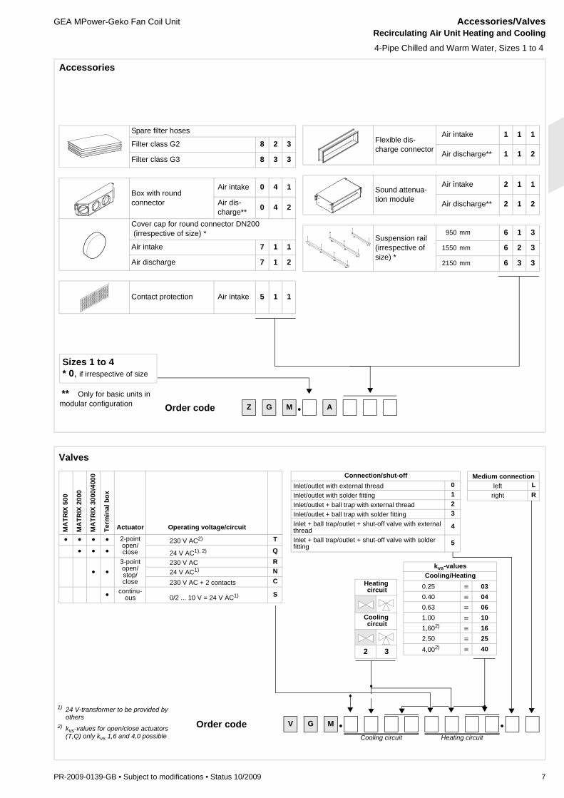
Accessories
Spare filter hoses
Filter class G2 8 2 3
Filter class G3 8 3 3
Box with roundconnector
Air intake 0 4 1
Air dis-charge** 0 4 2
Cover cap for round connector DN200 (irrespective of size) *
Air intake 7 1 1
Air discharge 7 1 2
Contact protection Air intake 5 1 1
Flexible dis-charge connector
Air intake 1 1 1
Air discharge** 1 1 2
Sound attenua-tion module
Air intake 2 1 1
Air discharge** 2 1 2
Suspension rail (irrespective of size) *
950 mm 6 1 3
1550 mm 6 2 3
2150 mm 6 3 3
** Only for basic units in modular configuration
Sizes 1 to 4* 0, if irrespective of size
Z G M • AOrder code
MA
TRIX
500
MA
TRIX
200
0
MA
TRIX
300
0/40
00
Term
inal
box
Actuator Operating voltage/circuit
• • • • 2-point open/close
230 V AC2) T
• • • 24 V AC1), 2) Q
• •3-point open/stop/close
230 V AC R24 V AC1) N230 V AC + 2 contacts C
• continu-ous 0/2 ... 10 V = 24 V AC1) S
V G M • •Order codeCooling circuit Heating circuit
1) 24 V-transformer to be provided by others
2) kvs-values for open/close actuators (T,Q) only kvs 1,6 and 4,0 possible
Connection/shut-offInlet/outlet with external thread 0Inlet/outlet with solder fitting 1Inlet/outlet + ball trap with external thread 2Inlet/outlet + ball trap with solder fitting 3Inlet + ball trap/outlet + shut-off valve with external thread 4
Inlet + ball trap/outlet + shut-off valve with solderfitting 5
Medium connectionleft L
right R
kvs-valuesCooling/Heating
0.25 ≡ 030.40 ≡ 040.63 ≡ 061.00 ≡ 101,602) ≡ 162.50 ≡ 254,002) ≡ 40
Heating circuit
Cooling circuit
2 3
Valves

Recirculating Air Unit Heating or Cooling GEA MPower-Geko Fan Coil Unit2-Pipe Chilled or Warm Water
8 PR-2009-0139-GB • Subject to modifications • Status 10/2009
Sizes 1 to 4
Des
ign
Spee
d st
ages
Air
flow
rate
**Capacity stage 1 Capacity stage 2
Soun
d po
wer
air
inta
ke**
Soun
d po
wer
air
disc
harg
e**
Soun
d po
wer
cas
ing*
*
Size
Coo
ling
capa
city
Pres
sure
dro
p
Hea
ting
capa
city
Pres
sure
dro
p
Coo
ling
capa
city
Pres
sure
dro
p
Hea
ting
capa
city
Pres
sure
dro
p
QK ΔpK QH ΔpH QK ΔpK QH ΔpH[m3/h] kW kPa kW kPa kW kPa kW kPa dB(A) dB(A) dB(A)
Mod
ular
(G)
1 515 2,0 3,3 8,2 12,5 2,1 2,3 8,9 8,5 40 41 29
1Terminal box (select sheet steel electric switch box with GEA MATRIX)
2 685 2,4 4,7 10,2 18,9 2,7 3,5 11,3 13,3 44 46 34
3 915 2,9 6,8 12,5 27,7 3,4 5,2 14,1 20,2 52 54 41
4 1080 3,2 8,1 14,0* 31,7 3,8 6,3 15,8 25,0 56 58 45
5 1215 3,5 9,3 14,9* 31,7 4,1 7,3 17,3 29,6 58 62 48
1 685 3,0 9,1 11,1 27,6 3,3 6,4 12,0 18,7 42 45 32
22 930 3,7 13,5 14,1* 39,1 4,1 9,7 15,5 29,8 50 53 40
3 1115 4,2 16,6 16,0* 39,1 4,8 12,6 18,1* 39,0 54 58 44
4 1295 4,6 19,9 17,4* 39,1 5,3 15,2 20,1* 39,1 58 62 48
5 1555 5,1 24,1 19,3* 39,2 5,9 18,7 22,3* 39,1 63 67 53 Speed combination
1 815 3,1 2,0 13,6 8,1 3,2 1,2 14,3 5,2 38 38 27
3
A 1-2-3
2 1150 4,1 3,3 17,8 13,4 4,6 2,4 19,3 9,2 44 45 33 B 2-3-4
3 1380 4,7 4,2 20,3 17,2 5,3 3,1 22,3 12,0 48 49 37 C 3-4-5
4 1670 5,4 5,4 23,2 22,0 6,2 4,1 26,0 16,0 52 54 42 E 1-3-5
5 2020 6,0 6,6 26,2 27,7 7,0 5,1 29,7 20,5 57 60 47 H 1-2-3-4-5
1 1000 4,0 3,4 16,2 12,1 4,4 2,3 17,6 8,2 40 43 30
42 1380 5,1 5,3 20,9 19,3 5,7 3,8 23,0 13,6 47 50 37
3 1730 5,9 6,9 24,8 26,6 6,7 5,2 27,3 18,6 52 55 42Sheet steel electric switch box withterminal strip or for integrated control4 2065 6,6 8,5 27,8* 30,9 7,6 6,5 31,4 24,1 57 60 47
5 2460 7,3 10,2 30,8* 30,9 8,5 7,9 35,5 30,4 62 64 51
Com
pact
(M)
1 515 2,0 3,3 8,2 12,5 2,1 2,3 8,9 8,5 40 41 29
12 680 2,4 4,7 10,1 18,7 2,7 3,5 11,3 13,3 44 46 34
3 905 2,9 6,7 12,4 27,3 3,4 5,1 14,0 19,9 52 54 41
4 1065 3,2 8,0 13,9* 31,7 3,7 6,2 15,6 24,5 56 58 45
5 1190 3,4 9,1 14,7* 31,7 4,0 7,1 17,1 28,9 58 62 48
1 685 3,0 9,1 11,1 27,6 3,3 6,4 12,0 18,7 42 45 32
22 925 3,7 13,4 14,1* 39,1 4,1 9,6 15,6 30,1 50 53 40 Speed combination
3 1105 4,1 16,4 15,9* 39,1 4,7 12,5 17,8 38,5 54 58 44 K 1-2-3
4 1275 4,5 19,5 17,2* 39,1 5,2 14,8 19,8* 39,0 58 62 48 L 2-3-4
5 1515 5,0 23,4 19,0* 39,2 5,9 18,4 21,9* 39,1 63 67 53 M 3-4-5
1 805 3,1 1,9 13,3 7,8 3,2 1,2 14,1 5,1 38 38 27
3
O 1-3-5
2 1135 4,1 3,2 17,6 13,2 4,5 2,3 19,1 9,0 44 45 33 R 1-2-3-4-5
3 1360 4,7 4,1 20,1 16,8 5,2 3,0 21,9 11,6 48 49 37
4 1635 5,3 5,2 22,9 21,5 6,1 4,0 25,7 15,6 52 54 42
5 1965 5,9 6,4 25,8 26,8 6,8 4,9 29,1 19,7 57 60 47
1 1000 4,0 3,4 16,2 12,1 4,3 2,3 17,5 8,2 40 43 30
42 1365 5,1 5,2 20,7 19,0 5,7 3,8 22,6 13,1 47 50 37
3 1700 5,8 6,7 24,5 26,0 6,6 5,0 26,9 18,1 52 55 42
4 2015 6,5 8,3 27,4* 30,9 7,5 6,3 30,9 23,4 57 60 47
5 2375 7,2 10,0 30,3* 30,9 8,4 7,7 34,6 28,9 62 64 51
1 2Capacity stage
Medium connection - front connection side, facing discharge
Ceilingleft 3
right 4
Condensate linewith drainage 0with condensate pump *** 1
• • • •
G M . U W C .Ordercode
Data apply to basic units with filter class G2, without accessories and external pressure. Refer to table on page 24 for other operating points.* Capacity at max. allowed medium flow rate** Air flow rates and sound data for capacity stage 1*** Sheet steel electrical control box necessary
Filter
G2 mat filter 2G3 mat filter 3
Motor thermal contact
5-speed motor
Integrated TC 0
External TC 1
WWP 82/71 °CtL1 = +20 °C
CWP 6/12 °C tL1 = +23 °Cϕ1 = 50 % r.h.

GEA MPower-Geko Fan Coil Unit Accessories/Valves Recirculating Air Unit Heating or Cooling
PR-2009-0139-GB • Subject to modifications • Status 10/2009 9
2-Pipe Chilled or Warm Water, sizes 1 to 4
Accessories
Spare filter hoses
Filter class G2 8 2 3
Filter class G3 8 3 3
Box with roundconnector
Air intake 0 4 1
Air dis-charge** 0 4 2
Cover cap for round connector DN200(irrespective of size) *
Air intake 7 1 1
Air discharge 7 1 2
Contact protection Air intake 5 1 1
Flexible dis-charge connector
Air intake 1 1 1
Air discharge** 1 1 2
Sound attenua-tion module
Air intake 2 1 1
Air discharge** 2 1 2
Suspension rail (irrespective of size) *
950 mm 6 1 3
1550 mm 6 2 3
2150 mm 6 3 3
** Only for basic units in modular configuration
Sizes 1 to 4* 0, if irrespective of size
Z G M • AOrder code
Valves
MA
TRIX
500
MA
TRIX
200
0
MA
TRIX
300
0/40
00
Term
inal
box
Actuator Operating voltage/circuit
• • • • 2-point open/close
230 V AC2) T• • • 24 V AC1), 2) Q
⟨ • •3-point open/stop/close
230 V AC R24 V AC1) N230 V AC + 2 contacts C
• continu-ous 0/2 ... 10 V = 24 V AC1) S
V G M ⟨ 3 ⟨Order codeCooling/heating circuit
1) 24 V-transformer to be provided by others
2) kvs-values for open/close actuators (T,Q) only kvs 1,6 and 4 possible
Connection/shut-offInlet/outlet with external thread 0Inlet/outlet with solder fitting 1Inlet/outlet + ball trap with external thread 2Inlet/outlet + ball trap with solder fitting 3Inlet + ball trap/outlet + shut-off valve with external thread 4
Inlet + ball trap/outlet + shut-off valve with solder fitting 5
Medium connectionleft L
right R
kvs-valuesCooling/Heating
0.25 ≡ 030.40 ≡ 040.63 ≡ 061.00 ≡ 101,602) ≡ 162,50 ≡ 254.002) ≡ 40
Cooling/heating cir-
cuit
3

Recirculating Air Unit Heating GEA MPower-Geko Fan Coil Unit2-Pipe Warm Water
10 PR-2009-0139-GB • Subject to modifications • Status 10/2009
Sizes 1 to 4
Des
ign
Spee
d st
ages
Air
flow
rate
**Capacity stage 1 Capacity stage 2
Soun
d po
wer
air
inta
ke**
Soun
d po
wer
air
disc
harg
e**
Soun
d po
wer
cas
ing*
*
Size
Coo
ling
capa
city
Pres
sure
dro
p
Hea
ting
capa
city
Pres
sure
dro
p
Coo
ling
capa
city
Pres
sure
dro
p
Hea
ting
capa
city
Pres
sure
dro
p
QK ΔpK QH ΔpH QK ΔpK QH ΔpH[m3/h] kW kPa kW kPa kW kPa kW kPa dB(A) dB(A) dB(A)
Mod
ular
(G)
1 515 - - 8,2 12,5 - - 8,9 8,5 40 41 29
1Terminal box (select sheet steel electric switch box with GEA MATRIX)
2 685 - - 10,2 18,9 - - 11,3 13,3 44 46 34
3 915 - - 12,5 27,7 - - 14,1 20,2 52 54 41
4 1080 - - 14,0* 31,7 - - 15,8 25,0 56 58 45
5 1215 - - 14,9* 31,7 - - 17,3 29,6 58 62 48
1 685 - - 11,1 27,6 - - 12,0 18,7 42 45 32
22 930 - - 14,1* 39,1 - - 15,5 29,8 50 53 40
3 1115 - - 16,0* 39,1 - - 18,1* 39,0 54 58 44
4 1295 - - 17,4* 39,1 - - 20,1* 39,1 58 62 48
5 1555 - - 19,3* 39,2 - - 22,3* 39,1 63 67 53 Speed combination
1 815 - - 13,6 8,1 - - 14,3 5,2 38 38 27
3
A 1-2-3
2 1150 - - 17,8 13,4 - - 19,3 9,2 44 45 33 B 2-3-4
3 1380 - - 20,3 17,2 - - 22,3 12,0 48 49 37 C 3-4-5
4 1670 - - 23,2 22,0 - - 26,0 16,0 52 54 42 E 1-3-5
5 2020 - - 26,2 27,7 - - 29,7 20,5 57 60 47 H 1-2-3-4-5
1 1000 - - 16,2 12,1 - - 17,6 8,2 40 43 30
42 1380 - - 20,9 19,3 - - 23,0 13,6 47 50 37
3 1730 - - 24,8 26,6 - - 27,3 18,6 52 55 42Sheet steel electric switch box withterminal strip or for integrated control4 2065 - - 27,8* 30,9 - - 31,4 24,1 57 60 47
5 2460 - - 30,8* 30,9 - - 35,5 30,4 62 64 51
Com
pact
(M)
1 515 - - 8,2 12,5 - - 8,9 8,5 40 41 29
12 680 - - 10,1 18,7 - - 11,3 13,3 44 46 34
3 905 - - 12,4 27,3 - - 14,0 19,9 52 54 41
4 1065 - - 13,9* 31,7 - - 15,6 24,5 56 58 45
5 1190 - - 14,7* 31,7 - - 17,1 28,9 58 62 48
1 685 - - 11,1 27,6 - - 12,0 18,7 42 45 32
22 925 - - 14,1* 39,1 - - 15,6 30,1 50 53 40 Speed combination
3 1105 - - 15,9* 39,1 - - 17,8 38,5 54 58 44 K 1-2-3
4 1275 - - 17,2* 39,1 - - 19,8* 39,0 58 62 48 L 2-3-4
5 1515 - - 19,0* 39,2 - - 21,9* 39,1 63 67 53 M 3-4-5
1 805 - - 13,3 7,8 - - 14,1 5,1 38 38 27
3
O 1-3-5
2 1135 - - 17,6 13,2 - - 19,1 9,0 44 45 33 R 1-2-3-4-5
3 1360 - - 20,1 16,8 - - 21,9 11,6 48 49 37
4 1635 - - 22,9 21,5 - - 25,7 15,6 52 54 42
5 1965 - - 25,8 26,8 - - 29,1 19,7 57 60 47
1 1000 - - 16,2 12,1 - - 17,5 8,2 40 43 30
42 1365 - - 20,7 19,0 - - 22,6 13,1 47 50 37
3 1700 - - 24,5 26,0 - - 26,9 18,1 52 55 42
4 2015 - - 27,4* 30,9 - - 30,9 23,4 57 60 47
5 2375 - - 30,3* 30,9 - - 34,6 28,9 62 64 51
1 2Capacity stage
Medium connection - front connection side, facing discharge
Ceilingleft 3
right 4
• • • •
G M . U O W . 0Ordercode
Data apply to basic units with filter class G2, without accessories and external pressure. Refer to table on page 24 for other operating points.* Capacity at max. allowed medium flow rate** Air flow rates and sound data for capacity stage 1
Filter
G2 mat filter 2G3 mat filter 3
Motor thermal contact
5-speed motor
Integrated TC 0
External TC 1
WWP 82/71 °CtL1 = +20 °C

GEA MPower-Geko Fan Coil Unit Accessories/Valves Recirculating Air Unit Heating
PR-2009-0139-GB • Subject to modifications • Status 10/2009 11
2-Pipe Warm Water, Sizes 1 to 4
Accessories
Spare filter hoses
Filter class G2 8 2 3
Filter class G3 8 3 3
Box with roundconnector
Air intake 0 4 1
Air dis-charge** 0 4 2
Cover cap for round connector DN200(irrespective of size) *
Air intake 7 1 1
Air discharge 7 1 2
Contact protection Air intake 5 1 1
Flexible dis-charge connector
Air intake 1 1 1
Air discharge** 1 1 2
Sound attenua-tion module
Air intake 2 1 1
Air discharge** 2 1 2
Suspension rail (irrespective of size) *
950 mm 6 1 3
1550 mm 6 2 3
2150 mm 6 3 3
** Only for basic units in modular configuration
Sizes 1 to 4* 0, if irrespective of size
Z G M • AOrder code
MA
TRIX
500
MA
TRIX
200
0
MA
TRIX
300
0/40
00
Term
inal
box
Actuator Operating voltage/circuit
• • • • 2-point open/close
230 V AC2) T
• • • 24 V AC1), 2) Q
⟨ • •3-point open/stop/close
230 V AC R24 V AC1) N230 V AC + 2 contacts C
• continu-ous 0/2 ... 10 V = 24 V AC1) S
V G M • •Order codeHeating circuit
1) 24 V-transformer to be provided by others
2) kvs-values for open/close actuators (T,Q) only kvs 1,6 and 4,0 possible
Connection/shut-offInlet/outlet with external thread 0Inlet/outlet with solder fitting 1Inlet/outlet + ball trap with external thread 2Inlet/outlet + ball trap with solder fitting 3Inlet + ball trap/outlet + shut-off valve with external thread 4
Inlet + ball trap/outlet + shut-off valve with solderfitting 5
Medium connectionleft L
right R
kvs-valuesCooling/Heating
0.25 ≡ 030.40 ≡ 040.63 ≡ 061.00 ≡ 101,602) ≡ 162.50 ≡ 254,002) ≡ 40
Heating cir-cuit
2 3
Valves

Recirculating Air Unit Cooling GEA MPower-Geko Fan Coil Unit2-Pipe Chilled Water
12 PR-2009-0139-GB • Subject to modifications • Status 10/2009
Sizes 1 to 4
Des
ign
Spee
d st
ages
Air
flow
rate
**Capacity stage 1 Capacity stage 2
Soun
d po
wer
air
inta
ke**
Soun
d po
wer
air
disc
harg
e**
Soun
d po
wer
cas
ing*
*
Size
Coo
ling
capa
city
Pres
sure
dro
p
Hea
ting
capa
city
Pres
sure
dro
p
Coo
ling
capa
city
Pres
sure
dro
p
Hea
ting
capa
city
Pres
sure
dro
p
QK ΔpK QH ΔpH QK ΔpK QH ΔpH[m3/h] kW kPa kW kPa kW kPa kW kPa dB(A) dB(A) dB(A)
Mod
ular
(G)
1 515 2,0 3,3 - - 2,1 2,3 - - 40 41 29
1Terminal box (select sheet steel electric switch box with GEA MATRIX)
2 685 2,4 4,7 - - 2,7 3,5 - - 44 46 34
3 915 2,9 6,8 - - 3,4 5,2 - - 52 54 41
4 1080 3,2 8,1 - - 3,8 6,3 - - 56 58 45
5 1215 3,5 9,3 - - 4,1 7,3 - - 58 62 48
1 685 3,0 9,1 - - 3,3 6,4 - - 42 45 32
22 930 3,7 13,5 - - 4,1 9,7 - - 50 53 40
3 1115 4,2 16,6 - - 4,8 12,6 - - 54 58 44
4 1295 4,6 19,9 - - 5,3 15,2 - - 58 62 48
5 1555 5,1 24,1 - - 5,9 18,7 - - 63 67 53 Speed combination
1 815 3,1 2,0 - - 3,2 1,2 - - 38 38 27
3
A 1-2-3
2 1150 4,1 3,3 - - 4,6 2,4 - - 44 45 33 B 2-3-4
3 1380 4,7 4,2 - - 5,3 3,1 - - 48 49 37 C 3-4-5
4 1670 5,4 5,4 - - 6,2 4,1 - - 52 54 42 E 1-3-5
5 2020 6,0 6,6 - - 7,0 5,1 - - 57 60 47 H 1-2-3-4-5
1 1000 4,0 3,4 - - 4,4 2,3 - - 40 43 30
42 1380 5,1 5,3 - - 5,7 3,8 - - 47 50 37
3 1730 5,9 6,9 - - 6,7 5,2 - - 52 55 42Sheet steel electric switch box with terminal strip or for integrated control4 2065 6,6 8,5 - - 7,6 6,5 - - 57 60 47
5 2460 7,3 10,2 - - 8,5 7,9 - - 62 64 51
Com
pact
(M)
1 515 2,0 3,3 - - 2,1 2,3 - - 40 41 29
12 680 2,4 4,7 - - 2,7 3,5 - - 44 46 34
3 905 2,9 6,7 - - 3,4 5,1 - - 52 54 41
4 1065 3,2 8,0 - - 3,7 6,2 - - 56 58 45
5 1190 3,4 9,1 - - 4,0 7,1 - - 58 62 48
1 685 3,0 9,1 - - 3,3 6,4 - - 42 45 32
22 925 3,7 13,4 - - 4,1 9,6 - - 50 53 40 Speed combination
3 1105 4,1 16,4 - - 4,7 12,5 - - 54 58 44 K 1-2-3
4 1275 4,5 19,5 - - 5,2 14,8 - - 58 62 48 L 2-3-4
5 1515 5,0 23,4 - - 5,9 18,4 - - 63 67 53 M 3-4-5
1 805 3,1 1,9 - - 3,2 1,2 - - 38 38 27
3
O 1-3-5
2 1135 4,1 3,2 - - 4,5 2,3 - - 44 45 33 R 1-2-3-4-5
3 1360 4,7 4,1 - - 5,2 3,0 - - 48 49 37
4 1635 5,3 5,2 - - 6,1 4,0 - - 52 54 42
5 1965 5,9 6,4 - - 6,8 4,9 - - 57 60 47
1 1000 4,0 3,4 - - 4,3 2,3 - - 40 43 30
42 1365 5,1 5,2 - - 5,7 3,8 - - 47 50 37
3 1700 5,8 6,7 - - 6,6 5,0 - - 52 55 42
4 2015 6,5 8,3 - - 7,5 6,3 - - 57 60 47
5 2375 7,2 10,0 - - 8,4 7,7 - - 62 64 51
1 2Capacity stage
Medium connection - front connection side, facing discharge
Ceilingleft 3
right 4
Condensate linewith drainage 0with condensate pump *** 1
• • • •
G M . U W O .Ordercode
Data apply to basic units with filter class G2, without accessories and external pressure. Refer to table on page 24 for other operating points.* Capacity at max. allowed medium flow rate** Air flow rates and sound data for capacity stage 1*** sheet steel electrical control box necessary
Filter
G2 mat filter 2G3 mat filter 3
Motor thermal contact
5-speed motor
Integrated TC 0
External TC 1
CWP 6/12 °C tL1 = +23 °Cϕ1 = 50 % r.h.

GEA MPower-Geko Fan Coil Unit Accessories/Valves Recirculating Air Unit Cooling
PR-2009-0139-GB • Subject to modifications • Status 10/2009 13
2-Pipe Chilled Water, Sizes 1 to 4
Accessories
Spare filter hoses
Filter class G2 8 2 3
Filter class G3 8 3 3
Box with round connector
Air intake 0 4 1
Airdisharge** 0 4 2
Cover cap for round connector DN200(irrespective of size) *
Air intake 7 1 1
Air discharge 7 1 2
Contact protection Air intake 5 1 1
Flexible dis-charge connector
Air intake 1 1 1
Air discharge** 1 1 2
Sound attenua-tion module
Air intake 2 1 1
Air discharge** 2 1 2
Suspension rail (irrespective of size) *
950 mm 6 1 3
1550 mm 6 2 3
2150 mm 6 3 3
** Only for basic units in modular configuration
Sizes 1 to 4* 0, if irrespective of size
Z G M • AOrder code
MA
TRIX
500
MA
TRIX
200
0
MA
TRIX
300
0/40
00
Term
inal
box
Actuator Operating voltage/circuit
• • • • 2-point open/close
230 V AC2) T
• • • 24 V AC1), 2) Q
⟨ • •3-point open/stop/close
230 V AC R24 V AC1) N230 V AC + 2 contacts C
• continu-ous 0/2 ... 10 V = 24 V AC1) S
V G M • •Order codeCooling circuit
1) 24 V-transformer to be provided by others
2) kvs-values for open/close actuators (T,Q) only kvs 1,6 and 4,0 possible
Connection/shut-offInlet/outlet with external thread 0Inlet/outlet with solder fitting 1Inlet/outlet + ball trap with external thread 2Inlet/outlet + ball trap with solder fitting 3Inlet + ball trap/outlet + shut-off valve with external thread 4
Inlet + ball trap/outlet + shut-off valve with solderfitting 5
Medium connectionleft L
right R
kvs-valuesCooling/Heating
0.25 ≡ 030.40 ≡ 040.63 ≡ 061.00 ≡ 101,602) ≡ 162.50 ≡ 254,002) ≡ 40
Cooling cir-cuit
2 3
Valves

Pressure Drop in Heat Exchanger, Warm and Chilled Water GEA MPower-Geko Fan Coil Unit
14 PR-2009-0139-GB • Subject to modifications • Status 10/2009
50 60 70 1009080 200
150
450
400
350
300
250
900
800
700
600
500
1000
1500
2000
1/1
2/1
3/1
4/1
1/2
2/2
3/2
4/2
1/1
2/1
3/1
4/1
1/2
2/2
3/2
4/2
50 60 70 1009080 200
150
450
400
350
300
250
900
800
700
600
500
1000
1500
2000
0,5
3,53,0
2,5
2,0
1,5
1,00,90,80,7
0,6
8,07,0
6,0
5,04,54,0
15
109,0
25
20
0,5
3,53,0
2,5
2,0
1,5
1,00,90,80,7
0,6
8,07,0
6,0
5,04,54,0
15
109,0
25
20
50 60 70 1009080 200
150
450
400
350
300
250
900
800
700
600
500
1000
1500
2000
0,5
3,53,0
2,5
2,0
1,5
1,00,90,80,70,6
8,07,0
6,0
5,04,54,0
15
109,0
25
20
BG/LG* BG/LG*
1/1
2/1
3/1
4/1
1/2
2/2
3/2
4/2
BG/LG*
1/1
2/1
3/1
4/1 1/2
2/2
3/2
4/2
BG/LG*
0,5
3,53,0
2,5
2,0
1,5
1,00,90,80,70,6
8,07,0
6,0
5,04,54,0
15
109,0
25
20
50 60 70 1009080 200
150
450
400
350
300
250
900
800
700
600
500
1000
1500
2000
Cooling in 2-pipe system Heating in 2-pipe system
Water flow rate Vw [l/h]• Water flow rate Vw [l/h]
•
Cooling in 4-pipe system
P
ress
ure
drop
[kP
a]
Heating in 4-pipe system
Water flow rate Vw [l/h]• Water flow rate Vw [l/h]
•
* Size = Size, CS = Capacity stage
P
ress
ure
drop
[kP
a]
P
ress
ure
drop
[kP
a]
Pre
ssur
e dr
op [k
Pa]

GEA MPower-Geko Fan Coil Unit Power and Current Consumption
PR-2009-0139-GB • Subject to modifications • Status 10/2009 15
Note: the current table applies for modular units, capacity stage 1 and filter class G2. Power and current consumption decreases in other units variants and/or in case of mounted air side accessories and additional external static pressure drop.
Maximum power and current consumption
Size Speed Air flow rate [m3/h]Motor
Capacity [W] Current [A]
1
1 515 100 0.66
2 685 131 0.74
3 915 184 0.86
4 1080 197 0.91
5 1215 212 0.98
2
1 685 131 0.75
2 930 194 0.90
3 1115 212 0.98
4 1295 233 1.07
5 1555 278 1.32
3
1 815 133 0.78
2 1150 184 0.85
3 1380 221 1.02
4 1670 264 1.22
5 2020 300 1.38
4
1 1000 163 0.85
2 1380 225 1.04
3 1730 264 1.21
4 2065 303 1.38
5 2460 358 1.64

Capacity Overview for Different Operating Points GEA MPower-Geko Fan Coil UnitSize 1
16 PR-2009-0139-GB • Subject to modifications • Status 10/2009
* Capacity at max. allowed medium flow rate
0
20
40
60
80
100
120
140
160
180
0 200 400 600 800 1000 1200 1400
Speed 1
Speed 2
Speed 3
Speed 4
Speed 5
1: Compact basic unit (0 cap), basic unit CS2, air intake sound attenuator, contact protection, discharge plenum (0 cap)
2: Compact basic unit (1 cap), air intake plenum (0 cap), discharge plenum(1 cap)
3: Discharge sound attenuator4: Basic unit filter class G35: Air intake box (1 cap)6: Compact basic unit (2 caps), discharge
plenum (2 caps)7: Air intake box (2 cap)
Air flow rate [m³/h]
Sta
tic p
ress
ure
[Pa]
System Air flow rate
Capacity stage 1 Capacity stage 2Coolingcapacity
Pressure drop
Heatingcapacity
Pressure drop
Cooling capacity
Pressure drop
Heating capacity
Pressure drop
QK ΔpK QH ΔpH QK ΔpK QH ΔpH
[m3/h] [kW] [kPa] [kW] [kPa] [kW] [kPa] [kW] [kPa]
2-pi
pe s
yste
m
1200 3,5 9,2 14,8* 31,7 4,1 7,3 17,4 29,91150 3,4 8,7 14,5* 31,7 4,0 7,0 16,9 28,41100 3,3 8,3 14,2* 31,7 3,8 6,6 16,2 26,31050 3,2 7,9 13,8* 31,7 3,7 6,2 15,7 24,61000 3,1 7,6 13,2 30,8 3,6 5,9 15,1 22,9950 3,0 7,1 12,8 28,9 3,5 5,5 14,5 21,3900 2,9 6,7 12,4 27,1 3,4 5,2 14,0 20,1850 2,8 6,2 11,9 25,3 3,2 4,8 13,5 18,6800 2,7 5,8 11,5 23,5 3,1 4,4 12,7 16,7750 2,6 5,3 11,0 21,7 2,9 4,0 12,2 15,4700 2,5 4,9 10,4 19,5 2,8 3,6 11,4 13,6650 2,3 4,4 9,8 17,5 2,6 3,3 10,8 12,2600 2,2 4,0 9,3 15,8 2,5 2,9 10,2 11,0550 2,1 3,6 8,7 14,0 2,3 2,5 9,4 9,5500 1,9 3,1 8,0 12,0 2,1 2,2 8,7 8,1450 1,8 2,7 7,3 10,2 1,9 1,8 7,9 6,9400 1,6 2,2 6,7 8,5 1,7 1,5 7,1 5,6
4-pi
pe s
yste
m
1200 3,6 23,5 6,4* 12,7 3,5 9,2 7,9* 16,71150 3,5 22,5 6,3* 12,7 3,4 8,7 7,8* 16,71100 3,4 21,5 6,1* 12,7 3,3 8,3 7,6* 16,71050 3,3 20,4 6,0* 12,7 3,2 7,9 7,5* 16,61000 3,2 19,4 5,9* 12,7 3,1 7,6 7,4* 16,6950 3,1 18,3 5,8* 12,7 3,0 7,1 7,2* 16,6900 3,0 17,5 5,7* 12,7 2,9 6,7 7,1* 16,6850 2,9 16,4 5,6* 12,7 2,8 6,2 6,9* 16,6800 2,8 15,3 5,4* 12,7 2,7 5,8 6,7* 16,6750 2,7 14,1 5,3* 12,7 2,6 5,3 6,5* 16,6700 2,6 13,0 5,2* 12,7 2,5 4,9 6,3* 16,6650 2,5 11,9 5,0* 12,7 2,3 4,4 6,1* 16,6600 2,4 11,0 4,8* 12,7 2,2 4,0 5,9* 16,6550 2,2 9,8 4,6* 12,7 2,1 3,6 5,6* 16,6500 2,1 8,6 4,4* 12,7 1,9 3,1 5,3* 16,6450 1,9 7,6 4,2 11,5 1,8 2,7 5,0* 16,6400 1,8 6,4 3,9 10,2 1,6 2,2 4,7* 16,5
•• • •
WWP 82/71 °CtL1 = +20 °C
CWP 6/12 °C tL1 = +23 °CϕL1 = 50 % r.h.
GEA MPower-Geko Fan Coil Unit Overview of Acoustic Data for Different Operating Points Size 1
PR-2009-0139-GB • Subject to modifications • Status 10/2009 17
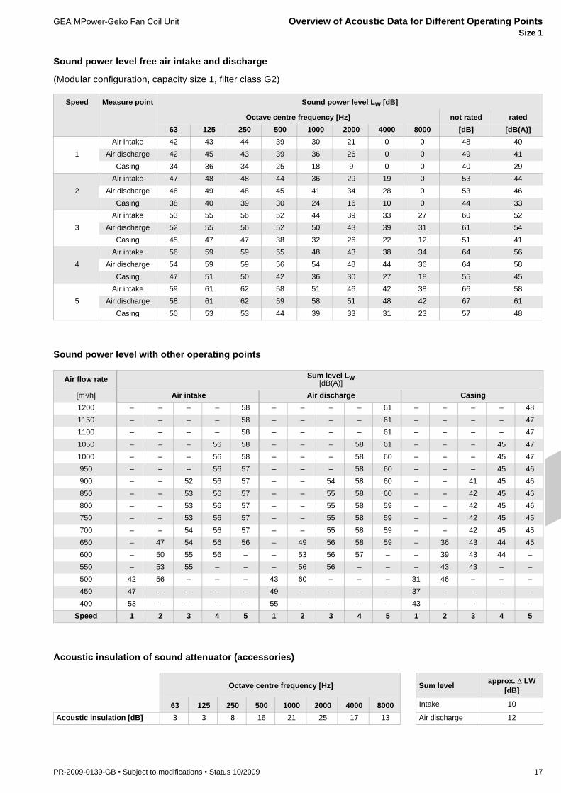
Sound power level free air intake and discharge
(Modular configuration, capacity size 1, filter class G2)
Sound power level with other operating points
Acoustic insulation of sound attenuator (accessories)
Speed Measure point Sound power level LW [dB]
Octave centre frequency [Hz] not rated rated63 125 250 500 1000 2000 4000 8000 [dB] [dB(A)]
1Air intake 42 43 44 39 30 21 0 0 48 40
Air discharge 42 45 43 39 36 26 0 0 49 41Casing 34 36 34 25 18 9 0 0 40 29
2Air intake 47 48 48 44 36 29 19 0 53 44
Air discharge 46 49 48 45 41 34 28 0 53 46Casing 38 40 39 30 24 16 10 0 44 33
3Air intake 53 55 56 52 44 39 33 27 60 52
Air discharge 52 55 56 52 50 43 39 31 61 54Casing 45 47 47 38 32 26 22 12 51 41
4Air intake 56 59 59 55 48 43 38 34 64 56
Air discharge 54 59 59 56 54 48 44 36 64 58Casing 47 51 50 42 36 30 27 18 55 45
5Air intake 59 61 62 58 51 46 42 38 66 58
Air discharge 58 61 62 59 58 51 48 42 67 61Casing 50 53 53 44 39 33 31 23 57 48
Air flow rate Sum level LW [dB(A)]
[m³/h] Air intake Air discharge Casing1200 – – – – 58 – – – – 61 – – – – 481150 – – – – 58 – – – – 61 – – – – 471100 – – – – 58 – – – – 61 – – – – 471050 – – – 56 58 – – – 58 61 – – – 45 471000 – – – 56 58 – – – 58 60 – – – 45 47950 – – – 56 57 – – – 58 60 – – – 45 46900 – – 52 56 57 – – 54 58 60 – – 41 45 46850 – – 53 56 57 – – 55 58 60 – – 42 45 46800 – – 53 56 57 – – 55 58 59 – – 42 45 46750 – – 53 56 57 – – 55 58 59 – – 42 45 45700 – – 54 56 57 – – 55 58 59 – – 42 45 45650 – 47 54 56 56 – 49 56 58 59 – 36 43 44 45600 – 50 55 56 – – 53 56 57 – – 39 43 44 –550 – 53 55 – – – 56 56 – – – 43 43 – –500 42 56 – – – 43 60 – – – 31 46 – – –450 47 – – – – 49 – – – – 37 – – – –400 53 – – – – 55 – – – – 43 – – – –
Speed 1 2 3 4 5 1 2 3 4 5 1 2 3 4 5
Octave centre frequency [Hz] Sum level approx. Δ LW [dB]
63 125 250 500 1000 2000 4000 8000 Intake 10
Acoustic insulation [dB] 3 3 8 16 21 25 17 13 Air discharge 12

Capacity Overview for Different Operating Points GEA MPower-Geko Fan Coil UnitSize 2
18 PR-2009-0139-GB • Subject to modifications • Status 10/2009
* Capacity at max. allowed medium flow rate
Speed 1
Speed 2
Speed 3
Speed 4
Speed 5
1: Contact protection2: Basic unit CS23: Air intake sound attenuator4: Compact basic unit (0 caps),
discharge plenum (0 caps)5: Air intake box (0 caps)6: Discharge sound attenuator7: Compact basic unit (1 cap), discharge
plenum (1 cap)8: Basic unit filter class G39: Air intake box (1 cap)10: Compact basic unit (2 caps),
discharge plenum (2 caps)11: Air intake box (2 caps)
Air flow rate [m³/h]
Sta
tic p
ress
ure
[Pa]
System Air flow rate
Capacity stage 1 Capacity stage 2Cooling
capacityPressure
dropHeating
capacityPressure
dropCooling
capacityPressure
dropHeating
capacityPressure
dropQK ΔpK QH ΔpH QK ΔpK QH ΔpH
[m3/h] [kW] [kPa] [kW] [kPa] [kW] [kPa] [kW] [kPa]
2-pi
pe s
yste
m
1550 5,1 24,0 19,3* 39,2 6,0 19,0 22,5* 39,11500 5,0 23,1 18,9* 39,2 5,9 18,6 22,0* 39,11440 4,9 22,5 18,5* 39,2 5,7 17,6 21,4* 39,11380 4,8 21,4 18,1* 39,2 5,6 16,7 20,8* 39,11320 4,6 20,3 17,6* 39,1 5,4 15,8 20,4* 39,11260 4,5 19,2 17,1* 39,1 5,2 14,8 19,8* 39,01200 4,4 18,1 16,7* 39,1 5,0 13,9 18,9* 39,01140 4,2 17,1 16,2* 39,1 4,8 13,0 18,3* 39,01080 4,1 16,0 15,7* 39,1 4,7 12,2 17,6 37,61020 3,9 14,9 15,1* 39,1 4,5 11,2 17,0 35,3960 3,8 14,1 14,5* 39,1 4,3 10,3 16,0 31,6900 3,6 12,9 13,8* 39,1 4,0 9,3 15,3 29,1840 3,4 11,8 13,2 38,0 3,8 8,4 14,3 25,8780 3,3 10,7 12,4 33,6 3,6 7,7 13,5 23,0720 3,1 9,6 11,7 30,4 3,4 6,9 12,6 20,4660 2,9 8,6 10,9 26,7 3,2 6,0 11,6 17,6600 2,7 7,4 10,1 23,0 2,9 5,2 10,7 15,0
4-pi
pe s
yste
m
1550 5,0* 53,8 8,3* 17,1 5,1 24,0 10,2* 22,61500 4,9* 53,8 8,3* 17,1 5,0 23,1 10,0* 22,61440 4,8* 53,8 8,1* 17,1 4,9 22,5 9,9* 22,61380 4,8 51,2 8,0* 17,1 4,8 21,4 9,7* 22,61320 4,6 48,7 7,9* 17,1 4,6 20,3 9,5* 22,51260 4,5 46,2 7,7* 17,1 4,5 19,2 9,4* 22,51200 4,4 43,7 7,6* 17,1 4,4 18,1 9,3* 22,51140 4,2 41,2 7,4* 17,1 4,2 17,1 9,0* 22,51080 4,1 38,7 7,3* 17,1 4,1 16,0 8,8* 22,51020 4,0 36,7 7,1* 17,1 3,9 14,9 8,6* 22,5960 3,8 34,1 6,9* 17,1 3,8 14,1 8,3* 22,5900 3,6 31,4 6,7* 17,0 3,6 12,9 8,1* 22,4840 3,5 28,8 6,6* 17,0 3,4 11,8 7,9* 22,4780 3,3 26,7 6,3* 17,0 3,3 10,7 7,6* 22,4720 3,1 23,8 6,1* 17,0 3,1 9,6 7,3* 22,4660 2,9 21,0 5,9* 17,0 2,9 8,6 7,0* 22,4600 2,7 18,7 5,6* 17,0 2,7 7,4 6,7* 22,4
•• • •
WWP 82/71 °CtL1 = +20 °C
CWP 6/12 °C tL1 = +23 °CϕL1 = 50 % r.h.

GEA MPower-Geko Fan Coil Unit Overview of Acoustic Data for Different Operating Points Size 2
PR-2009-0139-GB • Subject to modifications • Status 10/2009 19
Sound power level free air intake and discharge
(Modular configuration, capacity size 1, filter class G2)
Sound power level with other operating points
Acoustic insulation of sound attenuator (accessories)
Speed Measure point Sound power level LW [dB]
Octave centre frequency [Hz] not rated rated63 125 250 500 1000 2000 4000 8000 [dB] [dB(A)]
1Air intake 45 48 46 40 35 32 23 0 51 43
Air discharge 44 48 47 44 39 33 25 0 52 45Casing 36 40 37 28 22 17 9 0 43 32
2Air intake 53 56 53 48 43 38 34 26 59 50
Air discharge 51 56 55 52 48 43 39 31 60 53Casing 44 48 45 36 30 25 22 12 51 40
3Air intake 63 60 58 52 47 43 39 35 66 54
Air discharge 57 60 60 56 53 47 45 39 65 58Casing 53 52 50 40 35 30 28 20 57 44
4Air intake 58 63 61 55 52 47 43 40 67 58
Air discharge 59 64 64 59 57 51 49 44 69 62Casing 51 56 54 44 39 34 32 25 59 48
5Air intake 63 68 65 59 57 52 49 46 71 62
Air discharge 62 67 69 64 62 56 54 49 73 67Casing 54 60 58 48 44 38 37 31 63 53
Air flow rate Sum level LW [dB(A)]
[m³/h] Air intake Air discharge Casing1550 – – – – 62 – – – – 67 – – – – 531500 – – – – 62 – – – – 66 – – – – 521440 – – – – 62 – – – – 66 – – – – 521380 – – – – 61 – – – – 65 – – – – 511320 – – – – 61 – – – – 64 – – – – 511260 – – – 58 60 – – – 62 64 – – – 48 501200 – – – 58 60 – – – 61 63 – – – 48 501140 – – – 57 60 – – – 61 63 – – – 47 491080 – – 54 57 59 – – 58 60 62 – – 44 47 481020 – – 55 57 59 – – 58 60 61 – – 44 47 48960 – – 55 57 58 – – 58 60 61 – – 44 46 47900 – 50 55 57 58 – 54 57 59 60 – 40 44 46 47840 – 51 55 57 – – 54 57 59 – – 41 44 46 –780 – 52 55 – – – 54 57 – – – 41 44 – –720 – 53 55 – – – 55 57 – – – 42 44 – –660 46 54 – – – 48 55 – – – 35 42 – – –600 53 – – – – 54 – – – – 42 – – – –
Speed 1 2 3 4 5 1 2 3 4 5 1 2 3 4 5
Octave centre frequency [Hz] Sum level approx. Δ LW [dB]
63 125 250 500 1000 2000 4000 8000 Intake 10
Acoustic insulation [dB] 3 3 8 16 21 25 17 13 Air discharge 12

Capacity Overview for Different Operating Points GEA MPower-Geko Fan Coil UnitSize 3
20 PR-2009-0139-GB • Subject to modifications • Status 10/2009
* Capacity at max. allowed medium flow rate
= for values in sample calculation refer to pages 24 - 27
0
20
40
60
80
100
120
140
160
0 500 1000 1500 2000 2500
Speed 1
Speed 2
Speed 3
Speed 4
Speed 5
1: Contact protection2: Basic unit CS2 intake sound attenuator3: Compact basic unit (0 caps), discharge
plenum (0 caps)4: Air intake box (0 caps)5: Compact basic unit (1 cap), discharge
plenum (1 cap), discharge sound attenuator
6: Basic unit filter class G37: Air intake box (1 cap)8: Compact basic unit (2 caps), discharge
plenum (2 caps)9: Air intake box (2 caps)10: Compact basic unit (3 caps), discharge
plenum (3 caps)11: Air intake box (3 cap)
Air flow rate [m³/h]
Stat
ic p
ress
ure
[Pa]
System Air flow rate
Capacity stage 1 Capacity stage 2Cooling
capacityPressure
dropHeating
capacityPressure
dropCooling
capacityPressure
dropHeating
capacityPressure
dropQK ΔpK QH ΔpH QK ΔpK QH ΔpH
[m3/h] [kW] [kPa] [kW] [kPa] [kW] [kPa] [kW] [kPa]
2-pi
pe s
yste
m
2000 6,0 6,5 26,1 27,4 7,0 5,1 29,9 20,71900 5,8 6,2 25,2 25,8 6,8 4,8 28,7 19,21800 5,7 5,9 24,3 24,1 6,5 4,5 27,5 17,71700 5,4 5,5 23,5 22,5 6,3 4,2 26,6 16,71600 5,2 5,1 22,6 20,9 6,0 3,9 25,5 15,31500 5,0 4,7 21,6 19,4 5,7 3,5 23,9 13,71400 4,8 4,3 20,7 17,8 5,4 3,2 22,7 12,41300 4,5 3,9 19,4 15,8 5,1 2,9 21,5 11,31200 4,3 3,5 18,2 14,0 4,8 2,5 20,0 9,81100 4,0 3,1 17,2 12,6 4,4 2,2 18,8 8,71000 3,7 2,7 15,8 10,8 4,1 1,9 17,2 7,4900 3,4 2,3 14,7 9,4 3,6 1,5 15,7 6,3800 3,0 1,9 13,2 7,7 3,2 1,2 14,1 5,1700 2,7 1,5 11,8 6,3 2,9 1,1 12,6 4,1600 2,3 1,2 10,4 5,0 2,7 0,9 10,9 3,2500 2,1 0,9 8,8 3,7 2,4 0,7 9,2 2,3
4-pi
pe s
yste
m
2000 6,5 38,2 10,2* 21,6 6,0 6,5 14,5* 24,71900 6,4 36,7 10,0* 21,6 5,8 6,2 14,2* 24,71800 6,1 34,5 9,8* 21,5 5,7 5,9 13,9* 24,71700 5,9 32,4 9,7* 21,5 5,4 5,5 13,5* 24,71600 5,7 30,2 9,5* 21,5 5,2 5,1 13,1* 24,71500 5,5 28,0 9,2* 21,5 5,0 4,7 12,9* 24,71400 5,2 25,9 9,0* 21,5 4,8 4,3 12,5* 24,61300 5,0 24,1 8,8* 21,5 4,5 3,9 12,0* 24,61200 4,8 21,8 8,6* 21,5 4,3 3,5 11,5* 24,61100 4,5 19,5 8,2* 21,4 4,0 3,1 11,0* 24,61000 4,2 17,3 7,9* 21,4 3,7 2,7 10,5* 24,6900 3,9 15,1 7,5* 21,4 3,4 2,3 9,9* 24,6800 3,6 12,7 7,1* 21,4 3,0 1,9 9,3* 24,6700 3,2 10,8 6,7* 21,4 2,7 1,5 8,5 23,4600 2,9 8,7 6,2* 21,3 2,3 1,2 7,7 19,3500 2,5 6,7 5,6* 21,3 2,1 0,9 6,8 15,3
•• • •
WWP 82/71 °CtL1 = +20 °C
CWP 6/12 °C tL1 = +23 °Cϕ1 = 50 % r.h.

GEA MPower-Geko Fan Coil Unit Overview of Acoustic Data for Different Operating Points Size 3
PR-2009-0139-GB • Subject to modifications • Status 10/2009 21
Sound power level free air intake and discharge
(Modular configuration, capacity size 1, filter class G2)
Sound power level with other operating points
= for values in sample calculation refer to pages 24 - 27
Acoustic insulation of sound attenuator (accessories)
Speed Measure point Sound power level LW [dB]
Octave centre frequency [Hz] not rated rated63 125 250 500 1000 2000 4000 8000 [dB] [dB(A)]
1Air intake 42 43 42 36 29 0 0 0 47 38
Air discharge 42 42 42 36 33 19 0 0 47 38Casing 34 34 33 22 16 0 0 0 39 27
2Air intake 47 49 48 42 36 27 0 0 53 44
Air discharge 47 48 47 43 40 33 23 0 53 45Casing 39 41 39 29 22 15 5 0 44 33
3Air intake 50 53 52 46 40 33 25 0 57 48
Air discharge 50 52 52 47 44 38 30 0 57 49Casing 42 44 43 33 26 20 13 0 48 37
4Air intake 54 57 57 51 45 38 33 25 61 52
Air discharge 55 57 56 52 49 43 38 29 62 54Casing 47 49 48 38 31 26 21 10 53 42
5Air intake 60 62 61 55 50 44 40 35 66 57
Air discharge 61 62 61 57 54 49 45 38 67 60Casing 52 54 52 43 37 31 28 20 58 47
Air flow rate Sum level LW [dB(A)][m³/h] Air intake Air discharge Casing2000 – – – – 57 – – – – 60 – – – – 471900 – – – – 57 – – – – 59 – – – – 471800 – – – – 57 – – – – 59 – – – – 461700 – – – – 57 – – – – 59 – – – – 461600 – – – 53 57 – – – – 59 – – – 42 461500 – – – 53 57 – – – 55 59 – – – 43 461400 – – – 54 57 – – – 56 59 – – – 43 461300 – – 49 54 57 – – 50 56 59 – – 38 44 461200 – – 50 55 57 – – 52 57 59 – – 39 44 461100 – 45 51 55 57 – 46 53 57 59 – 34 41 45 461000 – 46 53 56 57 – 48 54 58 59 – 36 42 45 46900 – 48 54 56 57 – 50 55 58 59 – 37 43 46 46800 38 50 55 57 – 39 52 57 59 – 27 39 44 46 –700 43 52 57 – – 43 54 58 – – 32 41 46 – –600 47 54 58 – – 48 56 59 – – 37 43 47 – –500 52 56 – – – 53 58 – – – 41 45 – – –
Speed 1 2 3 4 5 1 2 3 4 5 1 2 3 4 5
Octave centre frequency [Hz] Sum level approx. Δ LW [dB]
63 125 250 500 1000 2000 4000 8000 Intake 10
Acoustic insulation [dB] 3 3 8 16 21 25 17 13 Air discharge 12

Capacity Overview for Different Operating Points GEA MPower-Geko Fan Coil UnitSize 4
22 PR-2009-0139-GB • Subject to modifications • Status 10/2009
* Capacity at max. allowed medium flow rate
0
20
40
60
80
100
120
140
160
0 500 1000 1500 2000 2500
Speed 1
Speed 2
Speed 3
Speed 4
Speed 5
Air volume flow [m³/h]
Sta
tic p
ress
ure
[Pa]
1: Contact protection2: Basic unit CS2, intake sound attenuator3: Air intake box (0 caps)4: Compact basic unit (0 cap), basic unit
filter class G3, air intake plenum (1 cap), air discharge plenum (0 cap)
5: Discharge sound attenuator6: Compact basic unit (1 cap), discharge
plenum (1 cap)7: Air intake box (2 caps)8: Compact basic unit (2 caps), discharge
plenum (2 caps)9: Air intake box (3 cap)10: Compact basic unit (3 caps), discharge
plenum (3 caps)
System Air flow rate
Capacity stage 1 Capacity stage 2Cooling capacity
Pressure drop
Heating capacity
Pressure drop
Cooling capacity
Pressure drop
Heating capacity
Pressure drop
QK ΔpK QH ΔpH QK ΔpK QH ΔpH
[m3/h] [kW] [kPa] [kW] [kPa] [kW] [kPa] [kW] [kPa]
2-pi
pe s
yste
m
2400 7,2 9,9 30,4* 30,9 8,5 7,9 35,3 30,12300 7,1 9,6 29,8* 30,9 8,3 7,6 34,2 28,42200 6,9 9,1 29,1* 30,9 8,1 7,2 33,1 26,62100 6,7 8,7 28,4* 30,9 7,8 6,8 31,9 24,82000 6,5 8,2 27,3* 30,9 7,5 6,4 31,0 23,61900 6,3 7,7 26,3 29,7 7,3 5,9 29,9 22,01800 6,1 7,2 25,4 27,9 7,0 5,5 28,7 20,41700 5,8 6,7 24,5 26,0 6,7 5,1 27,1 18,41600 5,6 6,2 23,6 24,2 6,4 4,7 26,1 17,21500 5,4 5,8 22,3 21,8 6,1 4,3 24,8 15,51400 5,1 5,4 21,1 19,7 5,8 3,9 23,4 14,01300 4,9 4,9 20,1 18,0 5,5 3,5 22,0 12,51200 4,6 4,4 18,9 16,1 5,1 3,1 20,5 10,91100 4,3 3,9 17,5 13,9 4,8 2,7 19,0 9,51000 4,0 3,4 16,2 12,1 4,4 2,3 17,6 8,2900 3,7 2,9 14,9 10,3 4,0 2,0 15,9 6,9800 3,3 2,4 13,6 8,8 3,5 1,6 14,3 5,6700 2,9 1,9 12,1 7,0 3,1 1,2 12,7 4,5
4-pi
pe s
yste
m
2400 7,5* 51,6 11,4* 23,8 7,2 9,9 16,3* 26,22300 7,4* 51,6 11,3* 23,8 7,1 9,6 16,0* 26,12200 7,2* 51,6 11,1* 23,8 6,9 9,1 15,8* 26,12100 7,1 49,0 10,9* 23,8 6,7 8,7 15,4* 26,12000 6,9 46,4 10,8* 23,8 6,5 8,2 15,1* 26,11900 6,7 43,8 10,6* 23,8 6,3 7,7 14,8* 26,11800 6,5 41,2 10,4* 23,8 6,1 7,2 14,3* 26,11700 6,2 38,6 10,2* 23,8 5,8 6,7 14,2* 26,11600 6,0 36,0 10,0* 23,7 5,6 6,2 13,8* 26,11500 5,8 33,9 9,7* 23,7 5,4 5,8 13,4* 26,11400 5,6 31,1 9,5* 23,7 5,1 5,4 12,9* 26,11300 5,3 28,4 9,2* 23,7 4,9 4,9 12,4* 26,11200 5,0 25,7 8,9* 23,7 4,6 4,4 12,0* 26,11100 4,7 23,2 8,5* 23,6 4,3 3,9 11,5* 26,11000 4,4 20,2 8,2* 23,6 4,0 3,4 10,9* 26,1900 4,0 17,4 7,8* 23,6 3,7 2,9 10,3* 26,0800 3,7 15,2 7,4* 23,6 3,3 2,4 9,7* 26,0700 3,4 12,6 6,9* 23,5 2,9 1,9 9,0* 26,0
•• • •
WWP 82/71 °CtL1 = +20 °C
CWP 6/12 °C tL1 = +23 °Cϕ1 = 50 % r.h.
GEA MPower-Geko Fan Coil Unit Overview of Acoustic Data for Different Operating Points Size 4
PR-2009-0139-GB • Subject to modifications • Status 10/2009 23
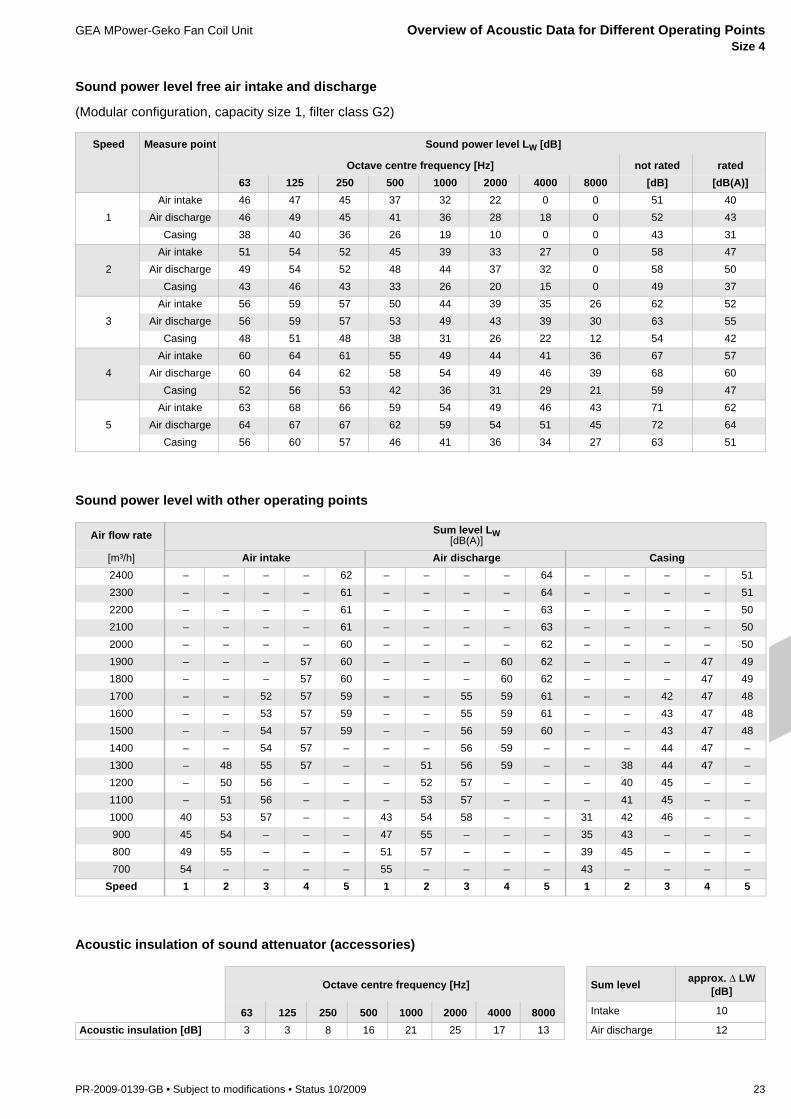
Sound power level free air intake and discharge
(Modular configuration, capacity size 1, filter class G2)
Sound power level with other operating points
Acoustic insulation of sound attenuator (accessories)
Speed Measure point Sound power level LW [dB]
Octave centre frequency [Hz] not rated rated63 125 250 500 1000 2000 4000 8000 [dB] [dB(A)]
1Air intake 46 47 45 37 32 22 0 0 51 40
Air discharge 46 49 45 41 36 28 18 0 52 43Casing 38 40 36 26 19 10 0 0 43 31
2Air intake 51 54 52 45 39 33 27 0 58 47
Air discharge 49 54 52 48 44 37 32 0 58 50Casing 43 46 43 33 26 20 15 0 49 37
3Air intake 56 59 57 50 44 39 35 26 62 52
Air discharge 56 59 57 53 49 43 39 30 63 55Casing 48 51 48 38 31 26 22 12 54 42
4Air intake 60 64 61 55 49 44 41 36 67 57
Air discharge 60 64 62 58 54 49 46 39 68 60Casing 52 56 53 42 36 31 29 21 59 47
5Air intake 63 68 66 59 54 49 46 43 71 62
Air discharge 64 67 67 62 59 54 51 45 72 64Casing 56 60 57 46 41 36 34 27 63 51
Air flow rate Sum level LW [dB(A)]
[m³/h] Air intake Air discharge Casing2400 – – – – 62 – – – – 64 – – – – 512300 – – – – 61 – – – – 64 – – – – 512200 – – – – 61 – – – – 63 – – – – 502100 – – – – 61 – – – – 63 – – – – 502000 – – – – 60 – – – – 62 – – – – 501900 – – – 57 60 – – – 60 62 – – – 47 491800 – – – 57 60 – – – 60 62 – – – 47 491700 – – 52 57 59 – – 55 59 61 – – 42 47 481600 – – 53 57 59 – – 55 59 61 – – 43 47 481500 – – 54 57 59 – – 56 59 60 – – 43 47 481400 – – 54 57 – – – 56 59 – – – 44 47 –1300 – 48 55 57 – – 51 56 59 – – 38 44 47 –1200 – 50 56 – – – 52 57 – – – 40 45 – –1100 – 51 56 – – – 53 57 – – – 41 45 – –1000 40 53 57 – – 43 54 58 – – 31 42 46 – –900 45 54 – – – 47 55 – – – 35 43 – – –800 49 55 – – – 51 57 – – – 39 45 – – –700 54 – – – – 55 – – – – 43 – – – –
Speed 1 2 3 4 5 1 2 3 4 5 1 2 3 4 5
Octave centre frequency [Hz] Sum level approx. Δ LW [dB]
63 125 250 500 1000 2000 4000 8000 Intake 10
Acoustic insulation [dB] 3 3 8 16 21 25 17 13 Air discharge 12

Samples for Capacity Definition GEA MPower-Geko Fan Coil Unit
24 PR-2009-0139-GB • Subject to modifications • Status 10/2009
The tables with capacity data on pages 6 to 12 indicated cooling and heating capacity as well as sound power level of the GEA MPower-Geko of modular configuration with a G2 filter and without mounted air side accessories and/or additional external static pressure.
A different unit configuration and using air side accessories like air intake and dis-charge plenums or sound attenuation modules change internal and external air side resistance. Air ducts and discharges connected by others can increase air side static pressure drop that must be covered by the GEA MPower-Geko. In such a way the air flow rate of the unit decreases which results in reduced cooling and/or heating capac-ity. The sound level emitted in air ducts by others and via unit casing is also influenced by the size of air side resistance.
The diagrams and tables given on pages 14 to 23 make it possible to calculate per-formance data for such operating conditions that are different from "a least complicated situation".
The following sample demonstrates the basic procedure:1: Pre-selection of unit size2: Determination of unit characteristics curve and actual operating point.3: Calculation of actual cooling and/or heating capacity4: If necessary - conversion of calorific output in other air/medium units5: Determination of actual sound power level6: Calculation of expected indoor sound pressure level
Example In an open plan office with a suspended ceiling of size 20 x 10 x 4 m 2 GEA MPower-Gekos in compact configuration are to be installed:
Cooling load: 8 kW at air intake 23°C/50 % r.h. and chilled water 6/12 °C (total indoor cooling load)
Max. sound pressure level: 45 dB(A) as of VDI 2081
Accessories: – 2 discharge cover caps DN200 (only 3 out of 5 connectors should be used)– Air intake sound attenuator– Intake flexible connection
Filter class: G3
External static pressuredrop:
35 Pa at 1000 m³/h (per unit)
1. Pre-selection of unit size Based on the projected air flow rate of around 1000 m³/h and max. allowed sound level unit size 3 in capacity stage 2 and speed 2 is selected. The following preliminary ca-pacity is calculated:
Air flow rate: 1000 m³/h at app. 40 Pa static pressure (refer to unit curve speed 2, page 20)
Cooling capacity: 4,1 kW (refer to table „Overview of capacity for different operating points size 3“ page 20)
Sound power level: 48 dB(A) (refer to table „Sound power level with other operating points“ on page 21)**) Note: In this case only discharge related sound level is considered, because a sound attenuator is pro-vided on the intake side.
2. Determination of unitcurve
In characteristics curve field on page 20 the curve of external static pressure drop is entered. The points of the curve can be calculated using the formuladp2 = dp1 * (V2/V1)².
Example dp1 = 35 PaV1 = 1000 m³/hV2 = 1500 m³/h
dp2 = 35 Pa * (1500/1000)² = 78,8 PaCharacteristics curves of additional unit internal pressure drops (capacity stage 2 and filter class G3) and pressure drops of air side accessories (air intake sound attenuator, compact basic unit with 2 caps) are added up to „unit characteristics curve“ which is a sum of all additional external and internal pressure drops.
GEA MPower-Geko Fan Coil Unit Samples for Capacity Definition
PR-2009-0139-GB • Subject to modifications • Status 10/2009 25
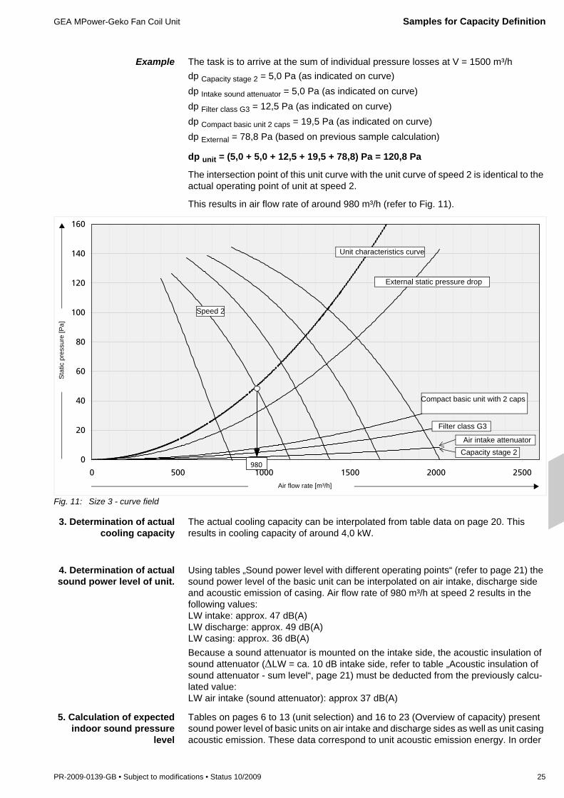
Example The task is to arrive at the sum of individual pressure losses at V = 1500 m³/hdp Capacity stage 2 = 5,0 Pa (as indicated on curve)dp Intake sound attenuator = 5,0 Pa (as indicated on curve)dp Filter class G3 = 12,5 Pa (as indicated on curve)dp Compact basic unit 2 caps = 19,5 Pa (as indicated on curve)dp External = 78,8 Pa (based on previous sample calculation)
dp unit = (5,0 + 5,0 + 12,5 + 19,5 + 78,8) Pa = 120,8 Pa
The intersection point of this unit curve with the unit curve of speed 2 is identical to the actual operating point of unit at speed 2.
This results in air flow rate of around 980 m³/h (refer to Fig. 11).
Fig. 11: Size 3 - curve field
3. Determination of actualcooling capacity
The actual cooling capacity can be interpolated from table data on page 20. This results in cooling capacity of around 4,0 kW.
4. Determination of actualsound power level of unit.
Using tables „Sound power level with different operating points“ (refer to page 21) the sound power level of the basic unit can be interpolated on air intake, discharge side and acoustic emission of casing. Air flow rate of 980 m³/h at speed 2 results in thefollowing values:LW intake: approx. 47 dB(A)LW discharge: approx. 49 dB(A)LW casing: approx. 36 dB(A)Because a sound attenuator is mounted on the intake side, the acoustic insulation of sound attenuator (ΔLW = ca. 10 dB intake side, refer to table „Acoustic insulation of sound attenuator - sum level“, page 21) must be deducted from the previously calcu-lated value:LW air intake (sound attenuator): approx 37 dB(A)
5. Calculation of expectedindoor sound pressure
level
Tables on pages 6 to 13 (unit selection) and 16 to 23 (Overview of capacity) present sound power level of basic units on air intake and discharge sides as well as unit casing acoustic emission. These data correspond to unit acoustic emission energy. In order
0
20
40
60
80
100
120
140
160
0 500 1000 1500 2000 2500980
Compact basic unit with 2 caps
Speed 2
Unit characteristics curve
Air flow rate [m³/h]
Sta
tic p
ress
ure
[Pa]
External static pressure drop
Filter class G3
Air intake attenuatorCapacity stage 2

Samples for Capacity Definition GEA MPower-Geko Fan Coil Unit
26 PR-2009-0139-GB • Subject to modifications • Status 10/2009
to determine actual sound level perceived by human ear at a certain point indoors,different factors need to be considered.
Sound energy emitted in the air ductwork by others is usually absorbed (= reduced) thanks to absorption and reflection process. The manufacturer usually provides infor-mation on certain components, e.g. acoustic insulation of a sound attenuator. Other influencing factors can be e.g. material and form of air ducts, form and number of cross section changes, duct ramifications, etc. As a rule, these can be estimated based on the empirical data of the manufacturer.
Sound energy emitted by unit casing in room direction is usually reduced only by the suspended ceiling. In this case material type and ceiling thickness as well as possibly used addition insulating material of suspended ceiling play a key role (e.g. mineral wool coating).
Supply and exhaust air flow entering and leaving the room through air ducts generates flow noise, that to a great extent depends on the used product (refer to manufacturer specifications). If the difference between sound level before the air duct opening and specific sound level of duct opening amounts to more than 10 dB, the increase of the total level is to be neglected. If the difference is smaller - the level with a higher figure must be increased by the level difference which is calculated according to the following formula:
Δ L = 10 * log (1+10^(L1-L2)/10)
In our example it is assumed that only one duct opening is used for each unit and the specific sound level difference exceeds 10 dB.
In order to define the anticipated indoor sound pressure level - the previously calcu-lated A-rated sound power level is used in connection with a conversiondiagram Fig. 12.
50 100 500 1000 5000200 2000 10000 30000
0,5 1 2 4 5 6 8 10 15 20 30 40 60 70
5
10
15
20
30
0
25
35
24
8
a = 0,03α = 0,05α = 0,1
α = 0,25α = 0,4
50
100
500
1000
5000
200
2000
20
10
5
Ric
htun
gsfa
ktor
Freifeld
gro�e
α = 0,15
Wohnr�ume, B�ros, Hotelzimmer
Konferenzr�ume, Theater
Krankenzimmer , kleine Kirchen
Schulr�umeLeses�le, Fernsehstudios
Rundfunkstudios
gro�e Kirchen
Kaufh�userMusikzimmer
Abstand von der Schallquelle [ m ]
Raumvolumen [ m 3 ]
Abso
rbtio
nsfl�
che
[ m
2 Sab
in ]
Ger�t grenzt an drei Raumfl�chen
Sch
allp
egel
diffe
renz
ΔL
=LW
- LP
[dB]
12
3
Fabrik- u. Schwimmhallen
Ger�t grenzt an zwei Raumfl�chen
Ger�t ist frei in der Mitte einer Fl�che
800
m3
Conversion of sound power level in sound pressure level
Absorption factor αA wall surface that absorbs all sound waves that hit it has an absorption factor of a = 1. The above am values represent the relationship between theactual and ideal absorption performance of a wall. They represent mean values.Absorption surface m2 (Sabin)This is the surface that completely absorbs all sound waves that hit it. It isnot identical to the entire room surface.
Unit is mounted free in the middle of a surface
Unit borders with two indoor surfaces
Free Sou
nd le
vel d
iffer
ence
ΔL
=LW
- LP
[dB
]
Unit borders with three indoor surfaces
Dire
ctio
n co
effic
ient
Room volume [m3]
Radio studios
Residential areas, offices, hotel
School classrooms
Factory halls and swimming pools
Concert halls
Department stores
Conference rooms, theatres
Hospital wards, small churches
Large churches
Reading rooms, TV studios
Abs
orpt
ion
surfa
ce [
m2 S
abin
]
Distance from sound source [m]Fig. 12

GEA MPower-Geko Fan Coil Unit Samples for Capacity Definition
PR-2009-0139-GB • Subject to modifications • Status 10/2009 27
1. Based on the room volume (800 m3), an absorption surface of approx. 100 m2 Sabin is estimated in accordance with the diagram Fig. 12“Homes, offices, hotel rooms, con-ference rooms”.
2. The mean distance to the duct opening is assumed to be approx. 3 m and the direc-tion coefficient to be “2”, Fig. 13. The intersection of the dotted sample lines in the dia-gram Fig. 12 mounts to the sound level difference: ΔL~12 dB.Direction coefficient 2(hemispherical radiation): unit is mounted free in the middle of a surfaceDirection coefficient 4(quarter-spherical radiation): unit borders with two room surfacesDirection coefficient 8(eight-spherical radiation): unit borders with three room surfaces
3. The anticipated A-rated sound pressurelevel LP for a unit is thus:LP = LW – ΔL = 49 dB(A) – 12 dB = 37 dB(A)
Sound level in case of 2 discharge openings increases according to thediagram Fig. 14, by approx. 3 dB.
Thus, the anticipated sound pressure level in the room amounts to:LPges. = LP + 3 dB = 37 dB(A) + 3 dB = 40 dB(A)
The approximate value for increased requirements (large office 45 dB (A) in table Fig. 15) is thus fulfilled.Table „A-sound pressure level“ LP1 as approximate value according to VDI 2081
Fig. 15 * = Mimimum requirements ** = Increased requirements1 Also refer to applicable building regulations, DIN standards and VDI guidelines (e.g. DIN 4109, DIN 1946, VDI 2058)2 Depending on application
2 48
Fig. 13: Direction coefficient
10
21
9
8
7
6
5
4
3
2
1
3 4 5 6 8 10Sou
nd le
vel i
ncre
ase
in d
B
Number of units
Fig. 14: Sound level increase (dB)
Room type A-sound level [dB(A)] Mean reverberation time [s]Apartment * **
(Hotel room) night 35/30 30/25 0.5Residential rooms day 35 30 0.5
AuditoriumsTV studio 30 25 1.5Concert halls 30 25 2.0Operas 30 25 1.5Theatre 35 30 1.0Cinema 40 30 1.0Lecture halls 40 35 1.0Reading rooms 40 35 1.0Seminar rooms 40 35 1.0Classrooms 40 35 1.0
OfficesConference rooms 40 35 1.0Leisure rooms 40 35 0.5Break rooms 40 35 0.5Small offices 40 35 0.5Large offices 50 45 0.5
Church 35 25 3.0Museums 40 35 1.5Service halls 45 40 1.5IT/Telecommunication room 55 40 1.5Laboratories 45 40 2.0Restaurants 40 to 552 1.0Kitchens 45 to 602 1.5Sales rooms 45 to 602 1.0

Installation Samples GEA MPower-Geko Fan Coil UnitOn-Demand Mounting of Intake and Discharge Side Accessories
28 PR-2009-0139-GB • Subject to modifications • Status 10/2009
Modular Version Compact Version
Fig. 16: Modular basic unit without accessories Fig. 17: Compact basic unit without accessories
Fig. 18: Modular unit with air discharge box Fig. 19: Compact unit with air intake box
Fig. 20: Air intake and discharge box Fig. 21: Air intake flexible connection + air intake soundattenuator
Fig. 22: Intake flexible connection + discharge sound attenuator + discharge box
Fig. 23: Air intake box + air intake sound attenuator
Fig. 24: Air intake box + air intake sound attenuator + air discharge sound attenuator + discharge box

GEA MPower-Geko Fan Coil Unit Dimensions of Basic Units
PR-2009-0139-GB • Subject to modifications • Status 10/2009 29
Fig. 25: Dimensions modular unit type
Fig. 26 Fig. 27: Dimensions compact unit type
Recommended service opening for maintenance work on the basic unit
1: Condensate tray2: Service panel3: Filter behind cover strip*) Dimensions of basic unit and service opening
Size b[mm]
bmax[mm]
B[mm]
1 682 1060 12602 982 1360 15603 1282 1660 18604 1432 1810 2010
Dimensions
Please consider that possibly further or larger openings must be provided if accessories are mounted.

Dimensions of Basic Units GEA MPower-Geko Fan Coil Unit
30 PR-2009-0139-GB • Subject to modifications • Status 10/2009
Fig. 28
Fig. 29 Fig. 30
Minimum mounting clearances
Medium connections (warm/chilled water)
2-pipe system heat exchanger CS1 and CS2Connections: 1/2" internal thread
Size Capacity stage
1 2A 190 165
Medium connections (warm/chilled water)
4-pipe system heat exchanger with heating and cooling circuitConnections: 1/2" internal thread
Pos. 1: cooling
Pos. 2: heating
12
Size Capacity stage
1 2A 215 215B 190 165C 30 30D 80 55E 205 230F 255 255
Unit weight and water charge of heat exchanger
Size
Weight1)
[kg] Water charge [l]
Modular type Compact type 2-pipe
4-pipe
Cooling circuit Heating circuit
CS 1 CS 2 CS 1 CS 2 CS 1 CS 21 37 46 1.64 2.10 1.32 1.64 0.32 0.432 45 54 2.26 3.01 1.82 2.26 0.44 0.603 55 66 2.88 3.84 2.31 2.88 0.57 0.764 61 76 3.19 4.25 2.56 3.19 0.63 0.85
1) Max. basic unit weight without accessories

GEA MPower-Geko Fan Coil Unit Accessory Sizes
PR-2009-0139-GB • Subject to modifications • Status 10/2009 31
Fig. 31
Fig. 32
Fig. 33
Fig. 34
Size 1 2 3 4b [mm] 682 982 1282 1482
Octave centre frequency [Hz] Sum level approx. Δ LW [dB]63 125 250 500 1000 2000 4000 8000 Air intake side 10
Acoustic insulation [dB] 3 3 8.0 16 21 25 17 13 Air discharge side 12
Spare filter hoses (1 set = 5 pieces)Quality class G2, G3 (EN 779); regenerative filter medium
Size Order-Nr. Filter quality Filter lengthG2 G3 L
1 ZGM.1A823 ZGM.1A833 approx. 7002 ZGM.2A823 ZGM.2A833 approx. 10003 ZGM.3A823 ZGM.3A833 approx. 13004 ZGM.4A823 ZGM.4A833 approx. 1450
Air intake flexible connector (material class B1)
Air discharge flexible connector(material class B1)
Size Order-Nr. Weight [kg]1 ZGM.1A111 2.92 ZGM.2A111 3.73 ZGM.3A111 4.54 ZGM.4A111 5.4
Size Order-Nr. Weight [kg]1 ZGM.1A112 2.92 ZGM.2A112 3.73 ZGM.3A112 4.54 ZGM.4A112 5.4
Size 4
Size 3
Size 2
Size 1
Air intake box with round connector,insulated (galvanized steel)
Air discharge box with round connector,insulated (galvanized steel)
Cover cap for all sizes(galvanized sheet steel, not insulated)
Size Order-Nr. Weight [kg]1 ZGM.1A041 5.82 ZGM.2A041 7.83 ZGM.3A041 9.94 ZGM.4A041 10.9
Size Order-Nr. Weight [kg]1 ZGM.1A042 5.82 ZGM.2A042 7.83 ZGM.3A042 9.94 ZGM.4A042 10.9
Size Order-Nr. WeightAir intake Air discharge [kg]
1-4 ZGM.0A711 ZGM.0A712 0.3
Air intake sound attenuator (galvanized sheet steel with internal acoustic and thermal insulation)
Air discharge sound attenuator (galvanized sheet steel with internal acoustic and thermal insulation))
Size Order-Nr. Weight [kg]1 ZGM.1A211 16.22 ZGM.2A211 21.63 ZGM.3A211 26.94 ZGM.4A211 30.2
Size Order-Nr. Weight [kg]1 ZGM.1A212 16.22 ZGM.2A212 21.63 ZGM.3A212 26.94 ZGM.4A212 30.2

Accessory Sizes GEA MPower-Geko Fan Coil Unit
32 PR-2009-0139-GB • Subject to modifications • Status 10/2009
In order to minimize the remaining structure borne sound it recommended to use standard spring elements.
Fig. 35
Fig. 36
Fig. 37
Fig. 38
Installation sample:Suspension rail with threaded rods M8+minor parts
Mounting with suspension rail and mounting adapter on one side and threaded rods on the other side.
Mounting length [mm]
Order-Nr. Weight [kg]
950 ZGM.0A613 2.41550 ZGM.0A623 4.02150 ZGM.0A633 5.5
Suspension rail 950 mm Cross section of suspension rail and mounting adapter
Rail length enough for a maximum 1 basic unit and 1 air intake and discharge box.
Suspension rail 1550 mm Rail length enough for a maxi-mum 1 basic unit, 1 sound at-tenuator and 1 air intake and discharge box.
Suspension rail 2150 mm Rail length enough for a maxi-mum 1 basic unit, 1 intake and discharge sound attenuator, 2 sound attenuators and 1 air intake and discharge box.

GEA MPower-Geko Fan Coil Unit Overview of Valves Selection Table
PR-2009-0139-GB • Subject to modifications • Status 10/2009 33
!
The following selection table presents all available valves models with main features and compatible control equipment.
The following symbols are used:„ “ = Valve type compatible with the corresponding control
panel or electric equipment.„–“ = Valve type not compatible with the corresponding control
panel or electrical equipment.
Valve type Function type
Control type
Voltage Compatible control equipment Controls by others MATRIX
500 MATRIX
2000 MATRIX
3000 MATRIX
4000Thermostat
switch
R 3 point (modulat-
ing)
230 V~ –
(only 2-pipe system)
–
N 3 point (modulat-
ing)
24 V~ –
(only 2-pipe system;
transformer by others
necessary)
(Trans-former by
others nec-essary)
(Trans-former by
others nec-essary)
–
C 3 point (modulat-
ing)
(2 floating auxiliary switches)
230 V~ –
(only 2-pipe system)
–
T 2 point (modulat-
ing)
230 V~
Q 2 point (modulat-
ing)
24 V~ –
(Transformer by others
necessary)
(Trans-former by
others nec-essary)
(Trans-former by
others nec-essary)
–
S continu-ous
24 V~(analogue-
signal 0..10 V)
– – – – –
AB AB
AB AB
AB A
B
AB AB
AB AB
AB AB

Overview of Valve Actuators GEA MPower-Geko Fan Coil UnitModulating Actuator 230 V AC / 3-point Operation / opt. 2 Floating Auxiliary Switches /
34 PR-2009-0139-GB • Subject to modifications • Status 10/2009
Fig. 39: For dimensions of continuous and virtually continuous valveactuators refer to table
Fig. 40: Dimensions of thermoelectric valve actuators in mm
Continuous virtually continuous actuators
Plastic motor casing
Floating auxiliary switch:Switch S1 (valve signal 100% open)Switch S2 (valve signal setting settable 0..100%)
Technical data:
Thermoelectric valve actuatorsPlastic actuator casing
Technical data:
A
CB
Function R C N S
Control mode 3-point 3-point 3-point continuous
Order-Nr. ac-tuator (loose) 308 173 312 370 311 947 311 948
Operating voltage
230 V AC50/60 Hz
230 V AC50/60 Hz
24 V AC50/60 Hz
0-10 V/24 V AC50/60Hz
Powerconsumption 7 VA 7 VA 0.7 VA 1.4 VA
Protection IP43 IP43 IP43 IP43
Run time 120 s/50 Hz 150 s/50 Hz 120 s/50 Hz 120s/50 Hz
Operating force [N] 180 180 180 180
Control stroke [mm] 6.5 6.5 6.5 6.5
Max. allowed ambient temp.
60 °C 60 °C 60 °C 60 °C
Cable [m] 2.7 2.7 2.7 2.7
LoadcapacityAuxiliary switch
-max. 5 (1) A/
250 Vmax. 100 mA/
24 V- -
Rated dimensions [mm]
A 100 109 100 100
B 61 85 61 61
C 49 49 49 49
Function T Q
Control mode 2-point 2-point
Order-Nr. actuator 240 5072 240 5073
Operating voltage 230 V AC50/60 Hz
24 V AC50/60 Hz
Power consumption [W] 3 3
Heat up current [A] 0.6 0.7
Rated current [A] 0.014 0.1
Protection type IP44 IP44
Run time (approx.) [min] 2.5 4
Operating force [N] 90 N 90 N
Control stroke [mm] 4 4
Max. ambient temp. 50 °C 50 °C
Connecting cable [m] 1 1
Modulating Actuator 24 V AC and 0-10 V/24 V AC / Thermoelectric Actuator 230 V AC and 24 V AC

GEA MPower-Geko Fan Coil Unit Overview of Valve Bodies Two and Three-Way
PR-2009-0139-GB • Subject to modifications • Status 10/2009 35
Fig. 41: Dimensions of two and three-way valves
Fig. 42: kVS-values for valves with spindle hub 6,5 mm
Fig. 43: kVS-values for valves with spindle stroke 2,5 mm
Two and three-way valves– Brass or red brass valve body– Stainless steel spindle and coneTechnical data:
Three-way valvesValve body with spindle stroke 2,5 mm:
Valve body with spindle stroke 6,5 mm:
Two-way valvesValve body with spindle stroke 2,5 mm:
Valve body with spindle stroke 6,5 mm:
Water flow rate V [l/h]
Pre
ssur
e dr
op Δ
p [k
Pa]
•
Water flow rate V [l/h]
Pre
ssur
e dr
op Δ
p [k
Pa]
•
Rated pressure 16 bar
max. medium temperature 120 °C
max. glycol concentration 50 %
Rated dimen-sions [mm]
a b c d e
Stroke 2,5 mm
G 1/2" AG 3/4" A
5666
4040
34.5 36.6
55
Stroke 6,5 mm
G 1/2" AG 3/4" A
5666
4040
3234
1818
DNkVS A-AB
[m3/h]kVS B-AB
[m3/h]Valve external
threadDpmax[kPa]
Order-Nr. (loose)
15 1.6 1.0 G 1/2" A 200 240 5070
20 4.0 2.5 G 3/4" A 100 240 5078
For suitable thermoelectric valve actuator refer to page 34
DNkVS A-AB
[m3/h]kVS B-AB
[m3/h]Valve external
threadDpmax[kPa]
Order-Nr. (loose)
15 0.25 0.16 G 1/2" A 600 240 5061
15 0.40 0.25 G 1/2" A 600 240 5062
15 0.63 0.40 G 1/2" A 600 240 5063
15 1.00 0.63 G 1/2" A 600 240 5064
20 1.60 1.00 G 1/2" A 300 240 5065
20 2.50 1.60 G 3/4" A 150 240 5066
20 4.00 2.50 G 3/4" A 50 240 5067
For suitable virtually continuous/continuous valve actuators refer to page 34
DNkVS A-AB
[m3/h]Valve external thread
Dpmax[kPa]
Order-Nr. (loose)
15 1.6 G 1/2" A 300 240 5068
20 4.0 G 3/4" A 100 240 5141
For suitable thermoelectric valve actuator refer to page 34
DNkVS A-AB
[m3/h]Valve external thread
Dpmax[kPa]
Order-Nr. (loose)
15 0.25 G 1/2" A 600 240 5054
15 0.40 G 1/2" A 600 240 5055
15 0.63 G 1/2" A 600 240 5056
15 1.00 G 1/2" A 600 240 5057
20 1.60 G 1/2" A 300 240 5058
20 2.50 G 3/4" A 150 240 5059
20 4.00 G 3/4" A 50 240 5060
For suitable virtually continuous/continuous valve actuators refer to page 34
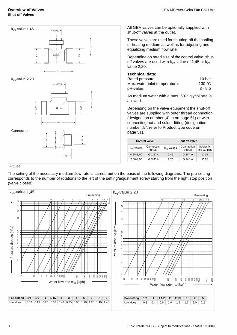
Overview of Valves GEA MPower-Geko Fan Coil UnitShut-off Valves
36 PR-2009-0139-GB • Subject to modifications • Status 10/2009
The setting of the necessary medium flow rate is carried out on the basis of the following diagrams. The pre-setting corresponds to the number of rotations to the left of the setting/adjustment screw starting from the right stop position (valve closed).
All GEA valves can be optionally supplied with shut-off valves at the outlet.
These valves are used for shutting-off the cooling or heating medium as well as for adjusting and equalizing medium flow rate.
Depending on rated size of the control valve, shut-off valves are used with kvs-value of 1,45 or kvs-value 2,20.
Technical data:Rated pressure: 10 barMax. water inlet temperature: 130 °CpH-value: 8 - 9,5
As medium water with a max. 50% glycol rate is allowed.
Depending on the valve equipment the shut-off valves are supplied with outer thread connection (designation number „4“ in on page 51) or with connecting nut and solder fitting (designation number „5“, refer to Product type code on page 51).
Fig. 44
���
��
���
���
���
�
SW24
66
3/4
"
3/4
"
33
����
��
��
kvs-value 1,45
kvs-value 2,20
Connection
Control valve Shut-off valve
kvs-values Connection thread kvs-values Connection
threadSolder fit-
ting Cu pipe
0.25-1,60 G 1/2" A 1.45 G 3/4" A Ø 15
2.50-4,00 G 3/4" A 2.20 G 3/4" A Ø 15
�
�
�
�
�
�
�
�
�
�
�
�
�
�
�
�
�
�
�
�
�
�
�
�
�
�
�
�
��� ��� � � ��� � � � �� �
�
�
�
Pre-setting 1/4 1/2 1 1 1/2 2 3 4 5 6 7 8kv-values 0.07 0.13 0.22 0.32 0.43 0.65 0.85 1.10 1.25 1.40 1.45
Pre
ssur
e dr
op Δ
p [k
Pa]
Pre-settingkvs-value 1,45
Water flow rate mW [kg/h]
�
�
�
�
�
�
�
�
�
�
�
�
�
�
�
�
�
�
�
�
�
�
�
�
�
�
�
��� � ���� � ���� � �
�
�
�
��
�
Pre
ssur
e dr
op Δ
p [k
Pa]
kvs-value 2,20Pre-setting
Water flow rate mW [kg/h]
Pre-setting 1/2 1 1 1/2 2 2 1/2 3 4 5kv-values 0.2 0.4 0.6 1.0 1.5 1.7 2.0 2.2

GEA MPower-Geko Fan Coil Unit Overview of Valves Ball Traps
PR-2009-0139-GB • Subject to modifications • Status 10/2009 37
The servicing of the ball cock is performed via a flat-bladed screwdriver.
Fig. 45
All GEA valves can be optionally supplied with ball traps.
These are necessary to shut-off cooling or heating medium.
Materials:Valve casing: BrassBall: Brass, groundGasket: Rubber
Technical data:Rated pressure: 10 barMax. water inlet temperature: 110 °Ckvs-value 6,70 m³/h
As a medium water and water/glycol is allowed.
Depending on the valve equipment ball traps are supplied with outer thread connection (designa-tions 2 and 4, see Product Type Code on page 51) or with connecting nut and solder fitting (designa-tions 3 and 5, see Product Type Code on page 51).
26
3/4“
3/4“
63
SW 27
27 36
3/4“
18
15
Ball trap
kvs-value Connection thread Solder fitting for Cu pipe
6.70 G 3/4" A Ø 15
900
800
700
600
500
1000
1500
3,0
2,0
5,0
4,0
15
10
20
2000
1,5
2,5
3,5
0,5
1,0
1100
1400
1300
1200
1900
1800
1700
1600
2500
3000
0,60,7
0,90,8
4,5
6,0
9,08,07,0
Pre
ssur
e dr
op Δ
p [k
Pa]
Water flow rate mW [kg/h] •
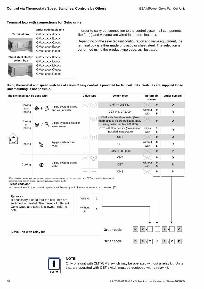
Control via Thermostat / Speed Switches, Controls by Others GEA MPower-Geko Fan Coil Unit
38 PR-2009-0139-GB • Subject to modifications • Status 10/2009
Terminal box with connections for Geko units
Using thermostat and speed switches of series C easy control is provided for fan coil units. Switches are supplied loose. Unit mounting is not possible.
Order code basic unit In order to carry out connection to the control system all components like fan(s) and valve(s) are wired in the terminal box.
Depending on the selected unit configuration and valve equipment, the terminal box is either made of plastic or sheet steel. The selection is performed using the product type code, as illustrated.
Terminal box GMxx.xxxx.AxxxxGMxx.xxxx.BxxxxGMxx.xxxx.CxxxxGMxx.xxxx.ExxxxGMxx.xxxx.Hxxxx
Sheet steel electric switch box
GMxx.xxxx.KxxxxGMxx.xxxx.LxxxxGMxx.xxxx.MxxxxGMxx.xxxx.OxxxxGMxx.xxxx.Rxxxx
The switches can be used with: Valve type Switch type Return air sensor
Order symbol
Cooling and
Heating
4-pipe system chilled and warm water
CMT (= 983 861) 0 Q
CET (= MCR2000)without 0 R
with 5
Cooling or
Heating
2-pipe system chilled or warm water
CMT with flow thermostat (flow thermostat to be ordered separately
using order number 902 035)0 Q
CET with flow sensor (flow sensor included in package)
without 1 Rwith 6
Heating 2-pipe system warm water
CMT 0 Q
CETwithout 0 R
with 5
––– ––– CMS (= 983 860) 0 P
Cooling 2-pipe system chilled water
CMT 0 Q
CETwithout 0 R
with 5
––– ––– CMS 0 P
NOTE!Only one unit with CMT/CMS switch may be operated without a relay kit. Units that are operated with CET switch must be equipped with a relay kit.
D 0 • 1 • AOrder code
Alternatively to a return air sensor, a room temperature sensor can be connected to a CET type switch. If a return air sensor is used, the fan mustbe operating in a continuous mode.Please consider:In connection with thermostat / speed switches only on/off valve actuators can be used (T).
Relay kitis necessary if up to four fan coil units are switched in parallel. The mixing of different Geko types and sizes is allowed - refer to note!
With kit 2
Without kit 0
Slave unit with relay kit
Order code D 0 • 2 0 1 • Z D

GEA MPower-Geko Fan Coil Unit Control via Thermostat / Speed Switches, Controls by Others
PR-2009-0139-GB • Subject to modifications • Status 10/2009 39
Operation of thermostat and speed switches
Additional sensors which are supplied loose and wired on-site by others should be ordered optionally (not in connection with the above-mentioned switch types CMT and CMS).
Switch type Functions
CMS – On/off switch– Fan speed selection switch 1-2-3
CMT – On/off switch– Fan speed selection switch 1-2-3– Setpoint setting indoor temperature 5 ... 35 °C (mechanical setting limitation)– Thermostat with neutral zone
CET – On/standby switch– Fan speed selection switch 1-2-3– Setpoint setting indoor temperature 5 ... 35 °C (mechanical setting limitation)– Thermostat with settable neutral zone– Enable input via potential free floating contact by others– Room frost protection– Connection possibilities for external room or return air sensor and flow sensor– Integrated indoor temperature sensor
Sensors Functions
Indoor temperature sensor903 414
Thermistor sensor for on-wall mounting– NTC-sensor element; resistance coefficient at 25 °C = 10 kΩ– Plastic casing: white, similar to RAL 9010– Protection class IP 20; dimensions in mm (W x H x D): 84 x 84 x 22
Flow sensor903 434
Thermistor sensor with tightening strap for mounting at inlet line– NTC-sensor element; resistance coefficient at 25 °C = 10 kΩ– Max. ambient temperature 100 °C– Protection class 2; cable length 2 m
Return air sensor903 474
Thermistor sensor for mounting in unit– NTC-sensor element; resistance coefficient at 25 °C = 10 kΩ– Protection class IP 43; casing dimensions (D x L): 6 x 100 mm; cable length 1,5 m– Max. ambient temperature 100 °C
Flow thermostat902 035
Flow thermostat for change-over between heating or cooling mode– Capillary length 1000 mm; switching points 19 °C/25 °C ± 1 K– Operating voltage 250 VAC 50/60 Hz– Dimensions in mm (W x H x D): 85 x 53 x 65– Flow thermostat in enclosed casing for wall mounting, the measuring capillaries are
mounted on the water inlet.
NOTE!Flow and return air sensor are integrated in the relevant controls packages and do not have to be selected separately if ordered using the package number.

GEA MPower-Geko Fan Coil Unit
40 PR-2009-0139-GB • Subject to modifications • Status 10/2009
GEA MATRIX® 500/2000System features:– Assigning of temperature 10... 30 °C– Assigning of fan speed– Limitable setting range– Change-over between normal / economy mode on control
panel– Room temperature measurement via control panel– External room temperature sensor can be connected*– Valve control (2-point)– Temperature control via fan on/off and/or valve(s)– Status signals via LED– Group control– Group switch-off in event of malfunction
Additional features with MATRIX 2000:– Extended temperature setpoint assignment.: 7...40 °C
(default 10..30 °C)– Temperature control via fan speed switch and valves– Network capability
* if required with add-on module
GEA MATRIX 3000
System features:– Assigning of temp. 7 ... 40 °C (default 10... 30 °C)– Assigning of fan speed– Limitable setting range– Change-over between normal / economy mode on control
panel– Input for change-over between normal / economy mode or
unit OFF with frost protection– Room temperature measurement via control panel– External room temperature sensor can be connected– Valve control (2-point)– Temperature control via fan and/or valve(s)– Room frost protection function– Status signals via LED– Operating and error messaging via
potential free change-over contacts– Stand alone unit or group control– Stand alone unit switch-off in event of malfunction– Network capability
MATRIX OP4CControl panel for MATRIX 500 control system– Pure white casing, IP20 protection type– Setpoint temperature setting– Fan speed selection switch 0 - A (continuous) - 1-2-3– Economy mode switch– LEDs for operation / malfunction / ext. control– Integrated room temperature sensor
MATRIX OP5CControl panel for MATRIX 500,like OP4C, but with:– Economy mode button
MATRIX OP20CControl panel for MATRIX 2000,like OP5C, but with:– Fan speed selection switch 0-A (Auto)-1-2-3
MATRIX OP21CControl panel for MATRIX 2000,like OP20C, but with:– Economy mode button
S
T
U
A
MATRIX OP30CControl panel for MATRIX 3000/4000 control system– Pure white casing, IP20 protection type– Setpoint temperature setting– Fan speed selection switch 0 - A (auto) - 1-2-3– LEDs for operation / malfunction / ext. control– Integrated room temperature sensor
MATRIX OP31CAs OP30C control panel, but also includes:– Normal / economy mode switch
MATRIX OP44CAs OP31C control panel, but also includes switches for:– Change-over between heating / cooling / automatic
operation– Change over between recirculating and mixed air mode
MATRIX OP50CControl panel for MATRIX 3000/4000 control system– Pure white casing, IP20 protection type– Menu-assisted operation via rotating switch– LCD display with plain text display– Status messages via pictograms– Integrated room temperature sensor
MATRIX OP51CAs OP50C control panel, but also includes:– Integrated weekly clock timer with programme for
holiday and special switching days
MATRIX.IRInfrared remote control for MATRIX 3000/4000control system– Black casing, similar to RAL 9004– LCD display approx. 45x30mm– Functions such as OP44C (without operation,
malfunction and ext. control messaging, no integr. room temperature sensor)
– Max. range 20m
B
C
D
E
F
on off
func
send
- +
%
N
Control System GEA MATRIXRecirculating Air Unit, Sizes 1-4
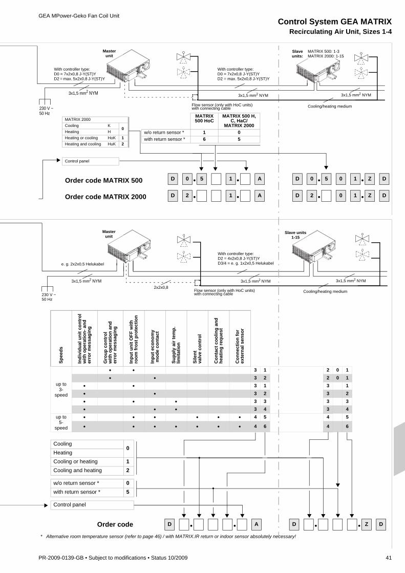
GEA MPower-Geko Fan Coil Unit
PR-2009-0139-GB • Subject to modifications • Status 10/2009 41
Masterunit
Slave units1-15
230 V ~50 Hz
3x1,5 mm2 NYM
Masterunit
Slaveunits:
MATRIX 500: 1-3MATRIX 2000: 1-15
Spee
ds
Indi
vidu
al u
nit c
ontr
olw
ith o
pera
tion-
and
erro
r mes
sagi
ng
Gro
up c
ontr
olw
ith o
pera
tion
and
erro
r mes
sagi
ng
Inpu
t uni
t OFF
with
room
fros
t pro
tect
ion
Inpu
t eco
nom
y m
ode
cont
act
Supp
ly a
ir te
mp.
limita
tion
Sile
ntva
lve
cont
rol
Con
tact
coo
ling
and
heat
ing
requ
est
Con
nect
ion
for
exte
rnal
sen
sor
up to3-
speed
• • 3 1 2 0 1• • 3 2 2 0 1
• • 3 1 3 1• • 3 2 3 2• • • 3 3 3 3• • • 3 4 3 4
up to5-
speed
• • • • • • 4 5 4 5
• • • • • • • 4 6 4 6
Cooling0
HeatingCooling or heating 1Cooling and heating 2
w/o return sensor * 0with return sensor * 5
Control panel
MATRIX 500 HoC
MATRIX 500 H, C, HaC/
MATRIX 2000w/o return sensor * 1 0with return sensor * 6 5
MATRIX 2000Cooling K
0Heating HHeating or cooling HoK 1Heating and cooling HuK 2
Control panel
230 V ~50 Hz
3x1,5 mm2 NYM
D • • A D • • Z D
3x1,5 mm2 NYM
3x1,5 mm2 NYM
D 0 • 5 1 • A
D 2 • 1 • A
D 0 • 5 0 1 • Z D
D 2 • 0 1 • Z D
Order code
Cooling/heating medium
Cooling/heating medium
* Alternative room temperature sensor (refer to page 46) / with MATRIX.IR return or indoor sensor absolutely necessary!
Order code MATRIX 500
Order code MATRIX 2000
With controller type:D0 = 7x2x0,8 J-Y(ST)YD2 = max. 5x2x0,8 J-Y(ST)Y
With controller type:D0 = 7x2x0,8 J-Y(ST)YD2 = max. 5x2x0,8 J-Y(ST)Y
e. g. 2x2x0,5 Helukabel
With controller type:D2 = 4x2x0,8 J-Y(ST)YD3/4 = e. g. 1x2x0,5 Helukabel
Flow sensor (only with HoC units)with connecting cable
Flow sensor (only with HoC units)with connecting cable
2x2x0,8
3x1,5 mm2 NYM
3x1,5 mm2 NYM
Control System GEA MATRIXRecirculating Air Unit, Sizes 1-4

GEA MATRIX Control System GEA MPower-Geko Fan Coil UnitSystem Description
42 PR-2009-0139-GB • Subject to modifications • Status 10/2009
MATRIX 500MATRIX 500 control system supports all basic functions (heating/cooling) of recircu-lating air fan coil unit. The controller can be used in the following unit types:– 2-pipe units „only heating“– 2-pipe units „only cooling“– 2-pipe units „cooing or heating“ (change over)– 4-pipe unit „cooling and heating“
The speed can be set manually and the unit switched off via the control panel. Valves with on/off or modulating control behaviour and a supply voltage of 230 V AC can be activated to control the heating and/or cooling capacity. Additionally, the MATRIX 500 enables monitoring of the fan motor via thermal contacts with external leads as well as the condensate water level for cooling units with a condensate pump. The connect-ed sensors are monitored as well.
The OP4/OP5 control panel enables the setpoint values to be set quickly and easily without extensive prior experience. Mechanical limit stops can be used to limit the set-ting range for the setpoint temperature and speed stage. Room temperature is meas-ured via a sensor integrated in the control panel. If the control panel is positioned in an unfavourable location (such as by the door), an external temperature sensor or re-turn air sensor can be connected (not possible on changeover systems). System faults are signalled centrally via the red “malfunction” LED and output using a change-over contact. If economy mode is activated, it is displayed via the yellow LED integrat-ed into the button. In addition to protection type IP20 (OP4 C/OP5 C), an IP54 control panel model (OP5 I) is available for moist areas.
The connection in the unit is made via plug-in cage clamps. Electronics, fans and valves (230V) are fused separately via two backup fuses on the power supply. A fuse of B 10A type must be supplied to provide the necessary circuit protection.
The MATRIX 500 can be used for controlling individual circulating air units and recir-culating air unit groups as well.
MATRIX 2000
The MATRIX 2000 control system is based on features incorporated in the MATRIX 500 system but also provides additional functions that can be summarized as follows:– Along with manual speed selection the fan control can be also carried out in a 3
speed mode based on the deviation of actual temperature from the setpoint.– With 2-pipe units 3-point modulating valve actuators can be controlled as well.– Besides, the control of valve actuators using 24V AC supply voltage is also
possible (transformer by others).
The direct connection of an external room temperature sensor is not possible with change over units, but can be performed via a Global Module. A fault message can also be received using a Global Module. Direct tapping is not possible.
Overview
Valve actuator type
2 point (modulating)
•
•
•
•
LEDs for operation/fault/ext.control
Setpoint temperature
Normal/economy mode buttonsSpeed stage selection switch
Valve actuator type
2 point (modu-lating)
3 point (modu-lating)
•
• •
• •

GEA MPower-Geko Fan Coil Unit GEA MATRIX Control System System Description
PR-2009-0139-GB • Subject to modifications • Status 10/2009 43
The OP20/OP21 control panel enables the setpoint values to be set quickly and easily without extensive prior experience. Mechanical limit stops can be used to limit the set-ting range for the setpoint temperature and speed stage. Room temperature is meas-ured via a sensor integrated in the control panel. If the control panel is positioned in an unfavourable location (such as by the door), an external temperature sensor or return air sensor can be connected (not possible on change over systems please use a Glo-bal Module). System faults are signalled centrally via the red “malfunction” LED. If economy mode is activated, it is displayed via the yellow LED integrated into thebutton.
In addition to protection type IP20 (OP20 C/OP21 C), an IP54 control panel model (OP21 I) is available for moist areas.
The connection in the unit is made via plug-in cage clamps. Electronics, fans and valves (230V) are fused separately via two microfuses on the power supply. A backup fuse B 10A must be supplied to provide the necessary circuit protection.
The MATRIX 2000 can be used for controlling individual recirculation air units and also recirculation air unit groups. The integrated MATRIX.Net bus system enables integra-tion of up to 16 several groups to one network. The combination with MATRIX 3000 controllers and connection of Global Modules and communication interfaces is also possible.
MATRIX 3000The Matrix 3000 control system is based on the MATRIX 2000 system and provides additional functions that can summarized are as follows:3-point valves with modulating control behaviour can be applied on 4-pipe systems. Mixed operation is also possible (2-point cooling valve / modulating heating valve or modulating cooling valve / 2-point heating valve).Operation and fault signals are output via two change-over contacts on the unit. The maximum load on the contacts at 230 V AC is 4 A ohmic / 2 A inductive.The supply air temperature can be limited for heating and cooling. Fixed and sliding limits can be defined.An external temperature sensor or return air sensor can be connected to all system types.An additional control input enables the following operating modes that can be set externally:– Normal/economy operation or– Unit OFF with frost protectionVarious types of control panels are available. The range varies from a simple variant with setpoint temperature and fan operating mode selection using infrared remote control to a control panel with display. The display unit can also be supplied with an integrated weekly timer.
MATRIX 4000
The Matrix 4000 control system is based on the MATRIX 2000/3000 system and pro-vides additional functions that can summarized are as follows:
In order to provide improved selection of heating/cooling capacity a five speed fan control is enabled.
For applications with highest comfort requirements electronic control elements pro-vide absolutely silent valve control.
Four additional control inputs enable external assignment of the following operating modes:– Normal mode– Economy mode– Free mode– Unit OFF with frost protection– Compulsory setting of a fan speed
A connection possibility for an outdoor sensor makes it possible to activate summer compensation. Outdoor air temperature value is automatically transmitted to all units connected within the MATRIX.Net.
LEDs for operation/fault/ext.control
Setpoint temperature switch
Normal/economy mode buttons
Speed stage selection switch
Valve actuator type
2 point (modu-lating)
3 point (modu-lating)
• •
• •
• •
/
5
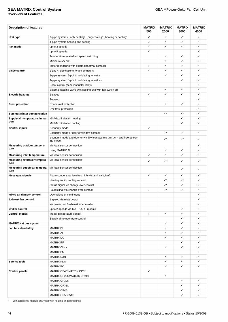
GEA MATRIX Control System GEA MPower-Geko Fan Coil UnitOverview of Features
44 PR-2009-0139-GB • Subject to modifications • Status 10/2009
Description of features MATRIX 500
MATRIX 2000
MATRIX 3000
MATRIX 4000
Unit type 2-pipe systems: „only heating“, „only cooling“; „heating or cooling“
4-pipe system heating and cooling
Fan mode up to 3 speeds
up to 5 speeds
Temperature related fan speed switching
Minimum speed 1
Motor monitoring with external thermal contacts
Valve control 2 and 4-pipe system: on/off actuators
2-pipe system: 3-point modulating actuator
4-pipe system: 3-point modulating actuators
Silent control (semiconductor relay)
External heating valve with cooling unit with fan switch off
Electric heating 1-speed
2-speed
Frost protection Room frost protection
Unit frost protection
Summer/winter compensation * *
Supply air temperature limita-tion
Min/Max limitation heating
Min/Max limitation cooling
Control inputs Economy mode
Economy mode or door or window contact *
Economy mode and door or window contact and unit OFF and free operat-ing mode * *
Measuring outdoor tempera-ture
via local sensor connection
using MATRIX.AI
Measuring inlet temperature via local sensor connection
Measuring return air tempera-ture
via local sensor connection **
Measuring supply air tempera-ture
via local sensor connection
Messages/signals Alarm condensate level too high with unit switch off
Heating and/or cooling request * *
Status signal via change-over contact *
Fault signal via change-over contact *
Mixed air damper control Open/close or continuous
Exhaust fan control 1 speed via relay output
via power unit / exhaust air controller
Chiller control up to 2 speeds via MATRIX.RF module
Control modes Indoor temperature control
Supply air temperature control
MATRIX.Net bus system
can be extended by: MATRIX.DI
MATRIX.AI
MATRIX.DO
MATRIX.RF
MATRIX.Clock
MATRIX.EM
MATRIX.LON
Service tools MATRIX.PDA
MATRIX.PC
Control panels MATRIX OP4C/MATRIX OP5x
MATRIX OP20C/MATRIX OP21x
MATRIX OP30x
MATRIX OP31x
MATRIX OP44x
MATRIX OP50x/51x
* with additional module only**not with heating or cooling units

GEA MPower-Geko Fan Coil Unit GEA MATRIX Control System Mounting Control Panels
PR-2009-0139-GB • Subject to modifications • Status 10/2009 45
As the control panel is split into two units, the control panel cover only needs to be snapped on the mounting plate during commissioning. This provides optimum protection against dirt and damage for the control panels during the construction phase.
The cable connection is established via cage clamps. This enables quick and easy use of solid and flexible cores.
To mount the control panel in a standard in-wall socket, corresponding drill holes need to be provided in the mounting plate.
The control panel can also be fitted directly on the wall (cable laid under plaster or in cavity wall).
IP54 control panels for moisture proof applications are available on request.
To prevent dirt accumulation or accidental operation, control panel covers are available as accessories (refer to Fig. 49 on page 46).

GEA MATRIX Control System GEA MPower-Geko Fan Coil UnitSensors/Accessories
46 PR-2009-0139-GB • Subject to modifications • Status 10/2009
Indoor sensor, order-Nr. 903.414Thermistor sensor for on-wall mounting– NTC sensor element– Plastic casing: white, similar to RAL 9010– Resistance coefficient at 25 °C = 10 kΩ– Protection type IP20– Dimensions in mm (W x H x D): 84 x 84 x 22The 903.414 indoor sensor replaces indoor sensor in the MATRIX OP XXC control panels. The additional sensor must be fitted if the control panel is mounted in a location that is unsuitable for accurate temperature measurement.
Fig. 46External sensor order-nr. 903.454Thermistor sensor for measuring ambient temperature e.g. for summer/winter compensation (according to DIN 1946 part 2/3)– NTC sensor element– Impact resistant white plastic casing– for outdoor wall mounting– PG bolts– Resistance coefficient at 25 °C = 10 kΩ– Protection type IP 54– Dimensions in mm (W x H x D): 65 x 50 x 37.5
Fig. 47Flow sensor order-nr. 903.434Thermistor sensor for mounting at inlet line– NTC sensor element– Sensor on basic plate; white plastic casing;
RAL 9010– Mounted with tightening strap at inlet line– Max. ambient temperature 100 °C– Dimensions in mm (W x H x D): 85 x 53 x 65– Resistance coefficient at 25 °C = 10 kΩ– Protection type IP 43
Fig. 48Unit capwhite order nr. OPD.C(for OP21C / OP30C / OP31C / OP44C)Light grey order-nr. OPD.I(for OP21I / OP30I / OP31I / OP44I)For covering operating elements of control panel
The control panel cover is hung into the guide slots of the control panel and protects the control panel from dirt accumulation and accidental operation.
Fig. 49

GEA MPower-Geko Fan Coil Unit Controls System GEA MATRIX
PR-2009-0139-GB • Subject to modifications • Status 10/2009 47
Global ModulesThe global modules of the MATRIX control system are designated for input and output of MATRIX system signals. The global modules enable the transmission of messages and operation statuses to external units as well as control via these external units. The modules can be integrated at any location within the MATRIX network. The network may contain and simultaneously operate a maximum of 2 MATRIX modules of the same type (DI,DO,AI) or 16 modules (LON). The modules are supplied with the default factory configuration. Configurations with other settings can be adjusted using the MATRIX.PC software..
Technical data:
Digital input module MATRIX.DI
The digital input module MATRIX.DI is used to receive 8 independent digital control signals.Factory configuration:
Digital output module MATRIX.DO
The module has 8 digital outputs with potential free change over contacts. Factory configuration:
Power supply 24 V DC ± 15 %Protection type IP 20Operation temperature 0 up to +45 °CFusing 10 A TMounting Mounting railMATRIX.DI max. current consumption 0,1 AMATRIX.DI dimensions 106 mm x 90 mm x 58 mmMATRIX.DO max. current consumption 0,14 AMATRIX.DO contact assignment 250 V/5 A (ohmic); 2 A (inductive)MATRIX.DO dimensions 160 mm x 90 mm x 58 mmMATRIX.AI nominal current consumption 0,03 AMATRIX.AI dimensions 160 mm x 90 mm x 58 mmMATRIX.LON nominal current consumption
0,045 A
MATRIX.LON dimensions 106 mm x 90 mm x 58 mm
Input valid for Closed contact results in1 all groups HVAC Heating Mode 2 all groups HVAC Cooling Mode 3 all groups Normal mode4 all groups Economy mode5 Group 0 Fan in speed 36 Group 0 Secondary air damper close7 Group 0 Secondary air damper open8 Group 0 Mixed air operation 100 %
Output valid for Energized relay signals1 all groups Operation2 Group 0 Fault message3 Group 0 Frost message4 Group 1 Fault message5 Group 1 Frost message6 Group 2 Fault message7 Group 2 Frost message8 all groups Fault message
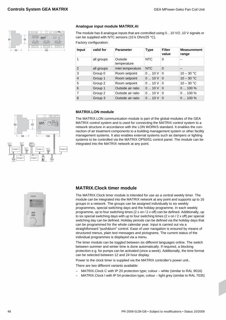
Controls System GEA MATRIX GEA MPower-Geko Fan Coil Unit
48 PR-2009-0139-GB • Subject to modifications • Status 10/2009
Gruppe 2
Gruppe 3 Gruppe 1
Gruppe 4 Gruppe 16
Analogue input module MATRIX.AI
The module has 8 analogue inputs that are controlled using 0…10 V/2..10 V signals or can be supplied with NTC sensors (10 k Ohm/25 °C).Factory configuration:
MATRIX.LON module
The MATRIX.LON communication module is part of the global modules of the GEA MATRIX control system and is used for connecting the MATRIX control system to a network structure in accordance with the LON WORKS standard. It enables the con-nection of air treatment components to a building management system or other facility management systems. It also enables external systems such as dampers or lighting systems to be controlled via the MATRIX OP50/51 control panel. The module can be integrated into the MATRIX network at any point.
MATRIX.Clock timer moduleThe MATRIX.Clock timer module is intended for use as a central weekly timer. The module can be integrated into the MATRIX network at any point and supports up to 16 groups in a network. The groups can be assigned individually to six weekly programmes, special switching days and the holiday programme. In each weekly programme, up to four switching times (2 x on / 2 x off) can be defined. Additionally, up to six special switching days with up to four switching times (2 x on / 2 x off) per special switching day can be defined. Holiday periods can be defined via the holiday days that can be programmed for the whole calendar year. Input is carried out via a straightforward “push&turn” control. Ease of user navigation is ensured by means of structured menus, plain text messages and pictograms. The current status of the individual programmes is displayed via a menu. The timer module can be toggled between six different languages online. The switch between summer and winter time is done automatically. If required, a blocking protection e.g. for pumps can be activated (once a week). Additionally, the time format can be selected between 12 and 24 hour display.Power to the clock timer is supplied via the MATRIX controller’s power unit..There are two different variants available:– MATRIX.Clock C with IP 20 protection type; colour – white (similar to RAL 9016)– MATRIX.Clock I with IP 54 protection type; colour – light grey (similar to RAL 7035)
Input valid for Parameter Type Filter value
Measurement range
1 all groups Outside temperature
NTC 0 –
2 all groups Inlet temperature NTC 0 –3 Group 0 Room setpoint 0 ... 10 V 0 10 – 30 °C4 Group 1 Room setpoint 0 ... 10 V 0 10 – 30 °C5 Group 2 Room setpoint 0 ... 10 V 0 10 – 30 °C6 Group 1 Outside air ratio 0 ... 10 V 0 0 ... 100 %7 Group 2 Outside air ratio 0 ... 10 V 0 0 ... 100 %8 Group 3 Outside air ratio 0 ... 10 V 0 0 ... 100 %

GEA MPower-Geko Fan Coil Unit Controls System GEA MATRIX
PR-2009-0139-GB • Subject to modifications • Status 10/2009 49
MATRIX.OP71 control panel for all groupsThe MATRIX.OP71 control panel is designed to be operated from one central point. It can integrated at any location within the MATRIX network and can simultaneously serve up to 16 groups.Up to 16 unit groups can be assigned to one cluster:– One unit group per each cluster– Each cluster with up to 16 unit groups.Clear text menus and "push&turn" function enable easy handling during operation or configuration. A maximum of 16 unit groups can be induvidually grouped to clusters. Using the control panel the wanted setpoints for temperature, fan speed, etc. can be assigned for each cluster. Thanks to control panel features comprising all groups, the necessary room or return air sensors are located in the respective groups (group locations).Local control panels (OP2xx, OP3xx, OP4xx, OP5x) can be additionally integrated in individual groups. Their functional scope can be defined and adjusted using the control panel for all groups. Thus, a relative daily setpoint can be entered via a local control panel, whereas the OP71C setpoint is assigned as standard.The integrated clock timer enables to assign 8 weekly programmes to clusters at any sequence. Each weekly programme enables to enter four switching times per day(2 x On/2 x Off), that can also be set to be valid for the whole day. Besides, it is possible to set 8 special switching days with up to four switching times (2 x On/2 x Off) per special switching day. Holidays / bank holidays can be set using the calendar annual programme. During holidays the unit can be set to operate in "unit off" or economy mode.The summer / winter time switch over is performed automatically.The control unit is currently supplied with 7 selectable languages:– German– English– French– Polish– Czech and– Hungarian.Two different variants are available:– MATRIX.OP71C with IP 20 protection type; colour – white (similar to RAL 9016)– MATRIXOP71I with IP 54 protection type; colour – light grey (similar to RAL 7035)

Controls System GEA MATRIX GEA MPower-Geko Fan Coil Unit
50 PR-2009-0139-GB • Subject to modifications • Status 10/2009
Service tools
MATRIX.PDA
The MATRIX.PDA service tool is used for setting parameters of the MATRIX control system and makes the commissioning and maintenance of systems considerably easier. The service tool can be connected via the service interface that is integrated into all control panels, controllers, global modules, the clock timer and the communication modules. Input is carried out via a straightforward “push&turn” control. The following main functions are available:– Automatic network scanning with display of detected users– Plain text error display– Modification of parameters such as temperature limits, times or control type– Display of actual values– Display of current unit status such as HVAC mode or valve position– Manual control of actuators such as fans and valves– Reading out, saving and writing of configuration dataThe service tool can be toggled between six different languages online. The unit is pro-tected from damage during transit and use via a rubber guard.
Service software MATRIX.PC
Based on the functions of the MATRIX.PDA service tool, the MATRIX.PC service software provides further comprehensive functions in the field of parameterization, commissioning and data recording of the GEA MATRIX controller system.The service software can be connected via the service interface that is integrated into all control panels, controllers, global modules, the timer and the communication modules. A USB interface is required on the PC. The enclosed adaptor establishes the necessary connection between the PC and the service interface.In addition to the functions of the MATRIX.PDA, the following main functions are also available:– Online display of module, status and network data– Recording and saving of temperature developments and switching states of the
actuators with adjustable sample rate– Offline parameterization– Programming of inputs and outputs provided for this purpose
(controllers, global modules)– Output of messages and network data– Parameterisation of controller and control panel functions– Input of sensor correction factorsPC system requirements:– PC with 233 MHz clock speed or higher– 20 MB of free hard drive space– Minimum screen resolution of 800x600 pixels– USB interface for CAN adaptorThe software can be run on the following operating systems:Windows 98 Second Edition; Windows 2000; Windows XPIn addition to the program CD, the installation instructions and interface module for connection to the USB port of the PC are also provided.

GEA MPower-Geko Fan Coil Unit Product Type Code
PR-2009-0139-GB • Subject to modifications • Status 10/2009 51
Controller type0 = Terminal box/
Matrix 5002 = MATRIX 20003 = MATRIX 30004 = MATRIX 4000
Unit type code Controls package Valve code
G M 1 1 . U 0 W 3 . A 0 0 G 2 D 2 . 0 0 1 . B A V G M . R 3 1 6 R 2 2 5 . 1 L
Capacity stage1 = Capacity stage 12 = Capacity stage 2
Speed stagesTerminal box with terminal stripA = Speed 1, 2, 3B = Speed 2, 3, 4C = Speed 3, 4, 5E = Speed 1, 3, 5H = Speed 1, 2, 3, 4, 5Sheet steel electric switch box with terminal strip or for integrated controlsK = Speed 1, 2, 3L = Speed 2, 3, 4M = Speed 3, 4, 5O = Speed 1, 3, 5R = Speed 1, 2, 3, 4, 5
Medium related functionHeating only0W = Warm water pumpCooling onlyW0 = Chilled water pumpCooling or heatingWC = WWP - CWPCooling and heatingWarm wa-ter
= WWP - CWP
Size1 = Size 12 = Size 23 = Size 34 = Size 4
Air flow functionU = Circulating air
Medium connection *Ceiling3 = left4 = right
* Front connection side, facing discharge** Steel sheet electrical switch box necessary
Filter2 = G2 mat filter3 = G3 mat filter
DesignG = Basic unit for modular designM = Compact unit with integrated discharge connector
Condensate pump0 = with condensate drain1 = with condensate pump **
Thermal contact0 = with integrated thermal contacts1 = with external (led out) thermal contacts
Controls package Nr.
control panelA = MATRIX OP21CB = MATRIX OP30CC = MATRIX OP31CD = MATRIX OP44CE = MATRIX OP50CF = MATRIX OP51CN = MATRIX.IRP = CMS = 983 860Q = CMT = 983 861R = CET = MCR 2000S = MATRIX OP4CT = MATRIX OP5CU = MATRIX OP20CZ = without control panel
Unit typeMaster unit, control panelA = Single/master unit, control
panel suppliedC = Master unit without control
panelD = Slave unit without control
panel
Function typeR = 3-point 230 VT = 2-point 230 VN = 3-point 24 VQ = 2-point 24 VS = 0-10 V, 24 VC = 3-point 230 V + 2 contacts
Valve body2 = 2-way3 = 3-way
Kvs-value03 = Kvs 0,25 (R, N, S, C)04 = Kvs 0,40 (R, N, S, C)06 = Kvs 0,63 (R, N, S, C)10 = Kvs 1,0 (R, N, S, C)16 = Kvs 0,40 (R, N, S, C, T, Q)25 = Kvs 2,5 (R, N, S, C)40 = Kvs 4,0 (R, N, S, C, T, Q)
Connection/shut-off0 = Inlet/outlet with external thread1 = Inlet/outlet with solder fitting2 = Inlet/outlet + ball trap with external thread3 = Inlet/outlet + ball trap with solder fitting4 = Inlet + ball trap/outlet + shut-off valve with external
thread5 = Inlet + ball trap/outlet + shut-off valve with solder fitting
Medium connectionL = leftR = right
Cooling/heating Heating circuit

S
RUS
PL
LV
LT
L
IS
GB
F
F
EST
E
DK
FIN
D
D
D
BY
CH
CZ
CZ
B
BG
BIH
Customer proximity, sales structures
Reachable always and everywhere!GEA Klimatechnik
GmbH & Co KG
A-4673 Gaspoltshofen
Tel. +43 / 7735 / 8000-0
GEA Happel Belgium N. V.
B-1130 Brussels
Tel. +32 / 2 / 2406161
EVISS Ltd.
BG-7000 Rousse
Tel . +359 / 82 / 81000
GEA Klimatechnik
GmbH & Co KG
RS-11070 Novi Beograd
Tel. +381 / 11 / 3193955
GEA Klimatechnik UAB
LT-01141 Vilnius
Tel. +370 / 5 / 2106060
ATC Klimatec Schweiz AG
CH-3065 Bolligen-Station
Tel. +41 / 31 / 9171919
GEA LVZ, a.s.
CZ-46312 Liberec
Tel. +420 / 48 / 5225-111
GEA Klimatizace spol. s r.o.
CZ-46312 Liberec
Tel. +420 / 48 / 5225-303
GEA Happel
Klimatechnik GmbH
D-44625 Herne
Tel. +49 / 2325 / 468-00
GEA Happel
Wieland GmbH
D-44625 Herne
Tel. +49 / 2325 / 468-754
GEA Deichmann
Umwelttechnik GmbH
D-36179 Bebra
Tel. +49 / 6622 / 504-0
GEA Delbag
Lufttechnik GmbH
D-44625 Herne
Tel. +49 / 2325 / 468-700
GEA Delbag-Luftfilter
Vertriebsgesellschaft mbH
D-10709 Berlin
Tel. +49 / 30 / 43592-3
GEA Klimateknik ApS
DK-2610 Rødovre
Tel . +45 / 38 / 887070
GEA Air Treatment
Marketing Services Int.
GmbH – oficina España
E-28036 Madrid
Tel. +34 / 91 / 3837701
GEA Klimatechnik UAB
LT-01141 Vilnius
Tel. +370 / 5 / 2106060
GEA Delbag
Filtration de l‘air
F-77450 Montry
Tel. +33 / 1 / 60043355
GEA Happel France sarl
F-59436 Roncq Cedex
Tel. +33 / 3 / 20689020
OY TEKNOCALOR AB
FIN-01300 Vantaa
Tel. + 358 / 10 / 8201100
GEA Denco Ltd.
UK-HR4 8DS Hereford
Tel. +44 / 1432 / 277 277
GEA Klimatechnika Kft
H-1037 Budapest
Tel. +36 / 1 / 4393200
GEA Klima-rashladna
tehnika d.o.o.
HR-10000 Zagreb
Tel. +385 / 1 / 6064900
Aspect Environmental Ltd.
Ardee, Co. Louth Ireland
Tel. +353 / 41 / 6858983
Rafn Jensson
IS-110 Reykjavik
Tel. +354 / 56 / 780-30
GEA Happel Luxembourg
L-4940 Bascharage
Tel. +352 / 26 / 502970
GEA Klimatechnik UAB
LT-01141 Vilnius
Tel. +370 / 5 / 2106060
GEA Klimatechnik UAB
LT-01141 Vilnius
Tel. +370 / 5 / 2106060
GEA Klimatechnik
GmbH & Co KG
RS-110 70 Novi Beograd
Tel. +381 / 11 / 3193955
GEA Klimaprodukter AS
N-0484 Oslo
Tel. +47 / 220 / 27990
GEA Happel Nederland B.V.
NL-2909 LL
Capelle a/d Ijssel
Tel. +31 / 10 / 2350606
RO
SK
SLO
SRB
TR
UA
UAE
IE
HR
H
MWE
N
NL
A P
D
D
The complete addresses are available on the Internet under: www.gea-air-eco2nomy.com.
www.gea-air-eco2nomy.com
xx/x
xxx
– PR
-xxx
x-xx
xx-x
xx
Nónio, Lda.
P-1269-090 Lisboa
Tel. +351 / 21 / 3826160
GEA Klimatyzacja Sp. z o.o.
PL-54610 Wroclaw
Tel. +48 / 71 / 3737952
GEA Klimatechnik s.r.l.
RO-300222 Timisoara
Tel. +40 / 356 / 423703
GEA Klimatechnik
GmbH & Co KG
RU-105094 Moskva
Tel. +7 / 495 / 9566674
GEA EXOS Ventilation AB
S-74528 Enköping
Tel. +46 / 171 / 85530
GEA Klimatizácia s.r.o.
SK-83104 Bratislava
Tel. +421 / 7 / 44457917
GEA Klimatizacijska
Tehnika d.o.o.
SI-1000 Ljubljana
Tel. +386 / 1 / 2573850
GEA Klimatechnik
GmbH & Co KG
RS-11070 Novi Beograd
Tel. +381 / 11 / 3193955
GEA ISISAN
TR-80700
Balmumcu Istanbul
Tel. +90 / 212 / 2757171
GEA Ukraina t.o.v.
UA-01135 Kyiv
Tel. +38 / 044 / 4619356
GEA Air Treatment
Middle East
UAE-Dubai
Tel. +971 / 4 / 887 3881
moJOMM
VJMN
PVJd
_==pìÄ
àÉÅí=íç
=ãçÇ
áÑáÅ~íáç
åë
pí~íìë=NMLOM
MV= =`ç
éóêáÖ
Üí=db^
=^áê=qêÉ~
íãÉå
í