a user-priority-driven multi-uav cooperative
TRANSCRIPT

Research ArticleA User-Priority-Driven Multi-UAV CooperativeReconnaissance Strategy
Zeyuan Liu , Cuntao Liu , Wendong Zhao , and Aijing Li
College of Communications Engineering, Army Engineering University of PLA, Nanjing 210042, China
Correspondence should be addressed to Wendong Zhao; [email protected]
Received 17 June 2021; Revised 29 August 2021; Accepted 7 September 2021; Published 11 October 2021
Academic Editor: Xingling Shao
Copyright © 2021 Zeyuan Liu et al. This is an open access article distributed under the Creative Commons Attribution License,which permits unrestricted use, distribution, and reproduction in any medium, provided the original work is properly cited.
This paper considers a reconnaissance scenario where multiple unmanned aerial vehicles (UAVs) provide services cooperativelyfor multiple users with different priorities. Although users all expect to acquire their needed information in a short time, thedegree of urgency to meet their demands is different when taking their diverse priorities into account. A priority-drivenmultiuser satisfaction model is designed, where users’ satisfaction is quantified based on their different priorities, informationacquisition demands, and the time they obtain their desired information. To ensure high priority users’ fast informationacquisition while avoiding excessive delay in low priority users’ information acquisition, a batchwise information backhaulstrategy is adopted. In each batch, a UAV is selected as the data ferry through a consultative mechanism to carry informationback to users. This reconnaissance process is formulated as a cooperative path planning problem, where the optimizationobjective is maximizing users’ total satisfaction, while an intelligent algorithm is proposed to solve this problem effectively. Thesimulation results show that compared with traditional path planning algorithms without considering user satisfaction, ourproposed algorithm can guarantee faster information acquisition for users with higher priorities, which leads to highersatisfaction. In addition, the applicability of our proposed reconnaissance strategy and path planning algorithm in differentsituations is also analyzed.
1. Introduction
Unmanned aerial vehicles (UAVs) have been widely used asmobile carriers to store information in many fields, such asmilitary reconnaissance and disaster relief, due to theirmobility and flexibility [1–3]. Usually, users need to obtaininformation on distant targets in a short time for their deci-sion. In this case, using UAVs to reconnoiter distant targetsand deliver information back to users is an excellent strategy[4]. Due to the limited capability of a single UAV, multipleUAVs are usually used to conduct cooperative reconnais-sance to deal with complex tasks [5], e.g., providing recon-naissance services simultaneously for multiple users withdifferent requirements or conducting a reconnaissance pro-cess with dynamic and uncertain task flows.
Unlike reconnaissance scenarios where only a single userexists [6, 7], we consider the scenario where multiple usersneed different target information, and all expect to obtain
this information in a short time. UAVs need to meet theirdifferentiated demands as best as possible while consideringservice fairness for different users. In addition, users mayhave different statuses or perform tasks with differentimportance; thus, we need to consider that they have differ-ent priorities. The higher the user’s priority, the faster theinformation acquisition should be guaranteed. To accom-plish this, effective task assignment and path planningstrategies are essential. Current studies on multi-UAV coop-erative reconnaissance with multiple users usually ignore thedifferences between users, i.e., users are supposed to obtainthe same target’s information or have the same priorities[8–11]. The other work did not consider different informa-tion acquisition time of different priority users [12–20], ortheir information backhaul strategies did not balance thedemand of different priority users well [21–25]. The impactof differences among users is not considered in task assign-ment and path planning. These above studies’ path planning
HindawiInternational Journal of Aerospace EngineeringVolume 2021, Article ID 9504056, 14 pageshttps://doi.org/10.1155/2021/9504056
methods and evaluation criteria do not work well in scenar-ios where users’ priorities and demands are different.
In this paper, we consider a reconnaissance scenariowhere multiple UAVs are used to provide services coopera-tively for multiple users with different priorities. Takingusers’ diverse priorities into account, a multiuser satisfactionmodel and a user-priority-driven reconnaissance strategy areproposed. Then, the cooperative path planning problem ofmultiple UAVs is considered and optimized with the goalof maximizing multiuser satisfaction. Our main contribu-tions are summarized as follows:
(i) A priority-driven multiuser satisfaction model isproposed, where users’ satisfaction is describedand quantified according to their different priorities,information acquisition demands, and the time theyobtain their desired information. It comprehen-sively considers the information acquisition timeof each user and achieves a good trade-off betweenthe needs of high priority and low priority users
(ii) A batchwise information backhaul strategy is pro-posed to ensure high priority users’ fast informationacquisition while avoiding excessive delay in lowpriority users’ information acquisition. In eachbatch, by adopting a cooperative consultative andinformation sharing mechanism, one of the taskexecution UAVs is selected as a data ferry to carrythe information collected by all UAVs back to users
(iii) The above reconnaissance process with a batchwiseinformation backhaul strategy is formulated as acooperative path planning problem, where theoptimization objective is maximizing users’ totalsatisfaction. To solve this problem effectively, abatchwise information transmission-based pathplanning algorithm (BITPP) is proposed. Simula-tion results show the effectiveness of our proposedBITPP algorithm in ensuring lower informationacquisition time and higher user satisfaction forusers with higher priorities
2. Related Work
To date, much research has been done on the path planningproblem in cooperative reconnaissance, which is beneficialfor shortening the information acquisition time as well asreducing UAVs’ energy consumption [12–21] Among them,to ensure users’ fast information acquisition, some studieshave focused on minimizing the maximum reconnaissancetime of UAVs [10–12]. However, in these studies, the differ-ence in the information acquisition demands of users wasnot well considered, and users’ information acquisition timewas not evaluated comprehensively regarding their differentpriorities. When considering tasks’ different priorities, sev-eral studies used the priorities as different weights to maxi-mize the task metrics’ weighted results [13–15]. Severalstudies designed reward values and penalty values pertainingdifferent tasks according to their priorities to maximize thefinal reward [16, 17]. However, these means cannot guaran-
tee that higher priority tasks can be completed before lowpriority tasks. If an evaluation criterion was to be that UAVscompleted their tasks sequentially according to the order oftheir priorities, it could cause too much delay for the com-pletion of low priority tasks, such as [18], or the low prioritytasks will be given up, such as [19], which is not fair to lowpriority users.
In addition, different information backhaul strategieshave been proposed and adopted in several studies. Amongthem, Ref. [20–22] favored a one-time strategy of informa-tion backhaul, where UAVs transmitted information tousers after finishing the reconnaissance process of all targets.Under this condition, higher priority users cannot obtaintheir desired information until the UAV assigned to provideservice for them has reconnoitered all targets, which will sig-nificantly prolong the time for their obtaining information.To address this problem, Ref. [23] proposed a multiroundinformation backhaul strategy, where UAVs conducted mul-tiple trips between the reconnaissance area and users to real-ize data unloading. During each trip, multiple UAVscooperatively performed reconnaissance a group of targetsand deliver corresponding information to the users whoneed it. Although higher priority users can obtain theirdesired information much more quickly, users with lowerpriorities will experience much more delay in their informa-tion acquisition, especially when users are far away from thereconnaissance area or too many round trips are neededbecause of several factors, e.g., the number of availableUAVs is limited, the distribution of target points is overlydiscrete, or the number of users is large, and the informationacquisition delay for lower priority users may be too long tobe acceptable. Ref. [24] adopted an immediate informationbackhaul strategy by using UAVs as fixed relays to constructavailable communication links between the reconnaissancearea and users. However, when facing situations where usersare far away from the reconnaissance area or the number ofusers is large, too many UAVs are needed to maintain effec-tive communication links, which will result in a huge recon-naissance cost.
3. System Model and Problem Formulation
3.1. Scenario Description. We consider a scenario in whichUAVs need to reconnoiter targets and distribute informa-tion to users in the user area. The set of users and targetsise denoted as M = f1,⋯Mg, m ∈M, and K = f1,⋯Kg, k∈K . Each user is interested in multiple target points, andthe information requirement relationship of users with tar-gets is denoted as a binary variable rkm, where r
km = 1 repre-
sents that m needs the information of k, and rkm = 0represents others. The number of UAVs is N , and this setis denoted as N = f1,⋯Ng, n ∈N . We assumed that UAVsneed to be near the user when they transmit information. Inaddition, it is assumed that the UAVs involved in reconnais-sance have sufficient flight time to complete the assigned tar-gets’ reconnaissance.
All users need to obtain information as soon as possible,and each user gives a degree of satisfaction for the UAVreconnaissance service according to their information
2 International Journal of Aerospace Engineering

acquisition time. The faster a user obtains the required infor-mation, the more satisfied it is with the UAVs’ reconnais-sance service. Each user has a priority value to measure theimportance of the user and determine the order in whichthe information is obtained. Users with higher priority needto obtain information faster than users with lower priority.λm represents the priority value of m. Although users allexpect a short information acquisition time, UAVs cannotensure that each user obtains the same high service qualityunder a limited number. Thus, we pursue maximizing theoverall user satisfaction and propose a batchwise informa-tion backhaul strategy to improve multiuser satisfaction.
3.2. Priority-Based Multiuser Satisfaction Model.We proposea priority-based multiuser satisfaction model to measure theinformation acquisition time of users with different priori-ties and measure the order in which the user obtains theinformation. In this model, sm represents the satisfaction ofuser m, and tm,end represents the time when m obtains allinformation it needs. The sm will change with the size of timetm,end. We assumed that each user has a uniform expectedtime for obtaining the needed information and is denotedas Texpect. We denoted a satisfaction constant γ to representone user obtaining the required information at time Texpect.When tm,end is earlier than Texpect , sm will equal γ, and whentm,end is later than Texpect, sm will decrease over time. In addi-tion, each user has a maximum tolerance time Tdeadline, anduser satisfaction becomes 0 when tm,end is later than Tdeadline.Thus, sm is calculated by equation (1).
sm =
γ tm,endTexpect
γ Tdeadline − Tm,endð ÞTdeadline − Texpect
Texpect < tm,end < Tdeadline
0 tm,endTdeadline
0BBBB@ :
ð1Þ
Multiuser satisfaction is represented by ξ, which is deter-mined following two principles. The first is that a user mustobtain information earlier than a user with lower priority.The second is that the impact of higher priority user satisfac-tion on ξ must be greater than the impact of lower priorityuser satisfaction. We denoted variable δ to measure whetherusers obtain information following the order of priority.When the user obtains information later than the user witha lower priority than it, δ takes the value of negative infinityto represent the penalty for violating the user priority order,which is calculated as follows:
δ =−∞ if tm,end − t j,end
� �λm − λj
� �0
0 other
: ð2Þ
Subsequently, each user’s priority values are normalized,and then the processing results are used as weighting coeffi-cients to weigh the satisfaction of each user. The equation ofξ is as follows:
ξ = δ + 〠M
m=1
λmsm∑M
m=1λm
!: ð3Þ
3.3. Batchwise Information Backhaul Strategy. This sectionproposes a batchwise information backhaul strategy; thatis, UAVs leave the reconnaissance area in batches to provideinformation for users. We divide the entire reconnaissanceprocess into L batches. In each batch, the UAV serves oneor more users. They first come in the reconnaissance phaseand reconnoiter the targets in which these users are inter-ested. K lðK l ⊆KÞ represents the target set that UAVs needto reconnoiter in the lth batch. K l,nðK l,n ⊆K lÞ representsthe target set assigned to n in the lth batch. Ml representsthe user set that UAVs need to serve in the lth batch.λmin½Ml� represents the priority value of the user with thelowest priority in Ml, and λmax½Ml� represents the priorityvalue of the user with the lowest priority in Ml. The priorityof users served in the previous batch is generally higher thanthat of users served in the latter batch, with the constraintexpressed as (4).
λmin Ml−1½ � > λmax Ml½ �: ð4Þ
After completing the reconnaissance of the assigned tar-get, the UAV enters the information sharing phase. A ferryUAV per batch is selected to share information with otherUAVs to obtain the information of K l. exitl represents theferry UAV in the lth batch. We assumed that other UAVsonly share information with the ferry UAV of the currentbatch and that ferry UAVs share information with onlyone UAV at the same time. We denoted srexitl ,n as the infor-mation sharing point of n and exitl, and they share informa-tion near it. Thus, in a batch, the ferry UAV has multipleinformation sharing points, and other UAVs have one infor-mation sharing point. These UAVs that share informationwith exitl move on to the next batch’s reconnaissance phaseimmediately after sharing information, while exitl proceedsto the information distribution phase. During the informa-tion distribution phase, exitl travels to the user area and dis-tributes information to users in order of priority. Note thatthe UAV finished information distribution returns to thetake-off position and is no longer involved in subsequentreconnaissance activity. The status of n in the batch l isdenoted as bl,n, where bl,n = 1 represents that n has enteredthe information distribution phase before entering the lthbatch. bl,n = 0 indicates that n continues to reconnoiter tar-gets in the lth batch. In addition, exitl can only be selectedamong the UAVs involved in the reconnaissance activitywithin the lth batch, with the constraint expressed as (5).
bl,exitl = 0&bl+1,exitl = 1: ð5Þ
To simplify the model, we assumed LN ; thus, only oneUAV per batch is selected to transmit information for theuser. The UAVs that are not selected at the last batch returndirectly to the take-off position after finishing the informa-tion sharing phase.
3International Journal of Aerospace Engineering

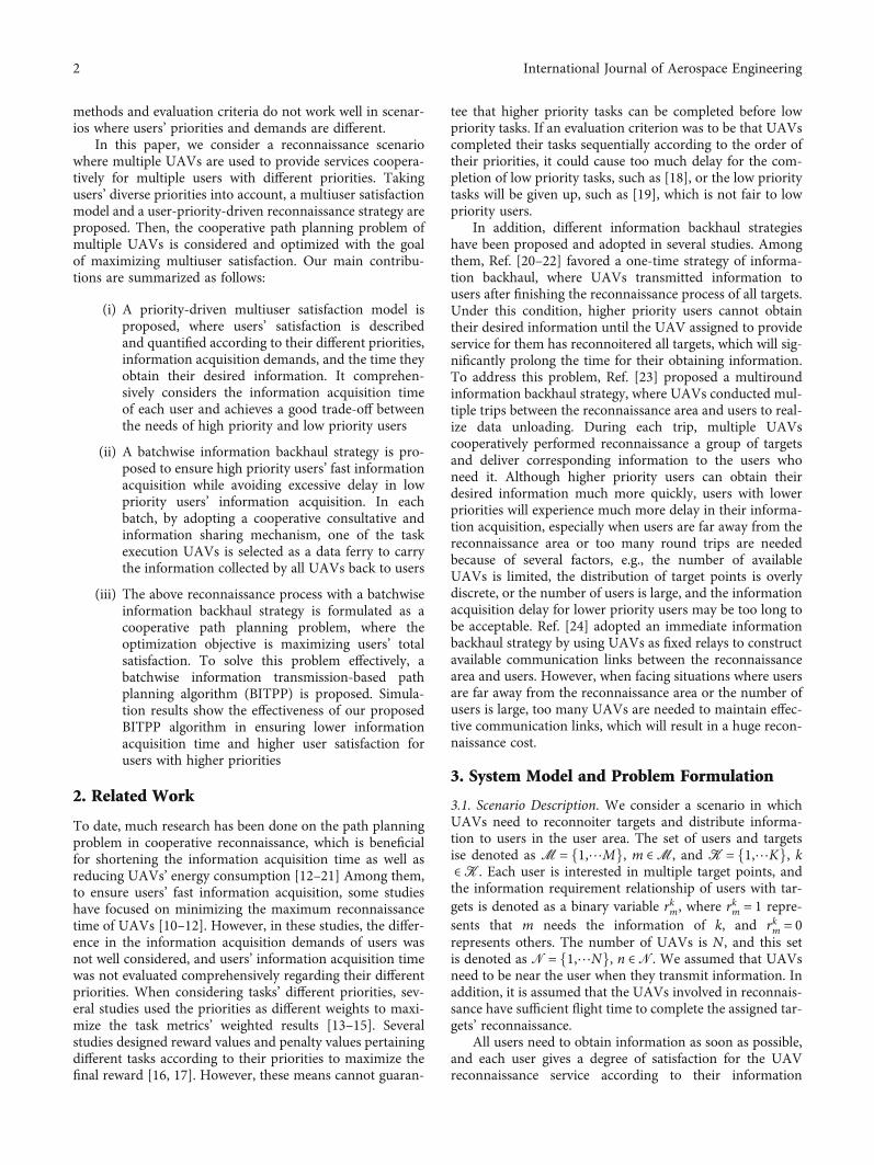
An example is shown in Figure 1. There are two UAVs,n1 and n2, and three users, m1, m2, and m3, and the priorityrelationship of users is λ3 < λ2 < λ1. Userm1 needs the infor-mation of target 1, m2 is interested in target 2, and m3 needsthe information of target 3. The user sets that are served ineach batch are M1 = fm1,m2g and M2 = fm3g. In the firstbatch, UAV n1 reconnoiters target 1, and n2 reconnoiterstarget 2 during the reconnaissance phase. Then, n1 and n2went to the information sharing position after finishing thereconnaissance of the assigned target. n1 obtains the infor-mation of target 2 by sharing information with n2. Subse-quently, n1 comes to the information distribution phaseand transmits information for users m1 and m2, while n2comes to the second batch and reconnoiter targets 3. Finally,n2 transmits information for m3.
3.4. Path Planning Problems. In this section, we model thereconnaissance process as a path planning problem to max-imize multiuser satisfaction. The two-dimensional trajectoryof the UAV n is denoted as pnðtÞ. In the lth batch, UAV firstreconnoiter targets of K l,n. The relationship between UAVand target reconnaissance is represented by binary functionf knðtÞ, where f knðtÞ = 1 means that the n reconnoiter for thetarget k at time t. f knðtÞ = 0 for other cases. UAVs must stayor hover in the area over the target for T target time to obtaininformation, and the constraint is expressed by Equations(6) and (7).
f kn tð Þ pn tð Þ − c kð Þj j = 0, ð6Þ
ðTmax
0f kn tð Þdt = T target, ð7Þ
where cðkÞ represents the target’s two-dimensional coor-dinates, and Tmax represents the UAV’s maximum flighttime. The UAV needs to return the take-off position beforereaching the maximum flight time. The constraint isexpressed as
pn Tmaxð Þ = pn 0ð Þ: ð8Þ
UAV n goes to the predetermined information sharingpoint after finishing the reconnaissance phase. The informa-tion sharing relationship between UAVs is represented as abinary function gkn,iðtÞ, where gk
n,iðtÞ = 1 means that i pro-vides information about target k for n at time t, and gk
n,iðtÞ= 0 represents the other cases. In addition, the remainingUAVs that share information with exitl can only providethe target information that they have obtained, with the con-straint shown in (9).
gkexitl ,i tð Þðt0f ki tð Þ/T targetdt: ð9Þ
When exitl and i share information, they are near theinformation sharing point, which can be approximatelyregarded as two UAVs in the same two-dimensional coordi-nate. This constraint is expressed as (10).
gkexitl ,i tð Þ pexitl tð Þ − pi tð Þ���
��� = 0: ð10Þ
Because the two UAVs are close to each other, the infor-mation transmission speed is faster, and the shared informa-tion time can be ignored compared with the flight time. Weassume that the two UAVs can complete the informationsharing in an instant. tl,exitl is used to indicate the time whenexitl ends the information sharing phase and enters theinformation distribution phase in the lth batch. After that,exitl will not participate in the subsequent reconnaissanceactivity. The constraints are shown in (11).
bl,exitl
ðTmax
tl,exitl
f kexitl tð Þ + 〠N
i=1gkexitl ,i tð Þdt = 0: ð11Þ
In the information distribution phase, the informationtransmission relationship between the UAV and user isdenoted as binary function smn , where smn = 1 indicates thatUAV n transmits information to userm, and smn = 0 indicatesthat n does not transmit information to m. We assumed thatthe UAV is close to the user when it transmits informationfor this user, and it finishes information transmissioninstantly. The constraint is shown in (12).
smexitl pexitl tm,endð Þ − c mð Þ���
��� = 0: ð12Þ
This equation indicates that the UAV must be at theuser’s location when its transmission pertains to the user,where cðmÞ represents the two-dimensional coordinate ofm, and tm,end represents the time when m obtains the needed
2
1
3P
1
2
3
Information sharing pointPP
111111 Target of user m1 interested
User m1
Take-off position
Path of UAV n1 in batch 1Path of UAV n2 in batch 1Path of UAV n2 in batch 2
Figure 1: Schematic of batchwise information backhaul strategy.
4 International Journal of Aerospace Engineering

information. exitl needs to transmit all the informationneeded by the user at one time. That is, exitl needs to obtainthis information through reconnaissance and informationsharing before transmitting them. The constraint is repre-sented as follows.
ðtm,end
0f kexitl tð Þ/T target + 〠
N
i=lgkexitl,i tð Þdt = smexitl r
km: ð13Þ
In addition, constraint (14) indicates that the time theuser obtains information is below the UAV’s maximumflight time, and constraint (15) indicates that each UAV fliesat a constant speed v.
tm,endTmax, ð14Þ
dpn tð Þdt
= v: ð15Þ
The UAV path planning optimization objective is tomaximize multiuser satisfaction, and the UAV path plan-ning problem is formalized as follows.
maxpn tð Þ,smn ,f kn tð Þ,gkn,l tð Þ
ξ
s:t: 6ð Þ − 15ð Þ: ð16Þ
4. Algorithm Description
The difficulty in solving the above problems is mainly due totwo aspects. First, the three functions f , g and s are tightlycoupled with many optimization variables. Second, the solu-tion to the UAV path planning function p is known as an NPproblem, which is challenging to find the optimal solution orcannot be solved in a short time [25]. The four functions arecoupled with each other, which makes the problem moredifficult to solve. To this end, we proposed the batchwise
information transmission path planning algorithm (BITPP)to solve the above problems.
Three subproblems need to be solved sequentially forplanning the UAV cooperative reconnaissance paths. Thefirst is to determine which users are served by UAVs in eachbatch. The second and third are to determine UAVs’ pathsof the reconnaissance phase and the information sharingphase during each batch. Thus, the BITPP algorithm is pro-posed, which includes three subalgorithms A1, A2, and A3to solve the above subproblems. The algorithm inputs areN , M, and K , and the output is P N . P N ðpn ∈P N Þ repre-sents the path set of the UAVs in set N and is constantlyupdated in the running of the BITPP algorithm. N l repre-sents the UAV set that continues to reconnoiter the targetsin the lth batch, and P N l
represents the path set of theUAVs in set N l, where P N l
⊆P N . BITPP first establishesan empty path array for each UAV (steps 1-4). Then, it usessubalgorithm A1 to determine the set of served users in eachbatch (step 5). Subsequently, L cycles are performed, andeach cycle determines the path of each UAV in a batch.For example, in the lth cycle, step 9 uses algorithm A2 todetermine the path of the UAVs in N l when they completethe reconnaissance phase in the lth batch, and step 10 deter-mines UAVs’ path when they complete the informationsharing phase by algorithm A3. In addition, step 10 alsodetermines the ferry UAV exitl and the set N l+1. Then, theinformation distribution paths for the ferry UAVs in thisbatch are determined (steps 11-13), where the functionrank() represents ranking the UAVs in order of priorityfrom large to small. Step 15 updates set PN and obtainsthe final path of each UAV.
4.1. Determining the Users Served in Each Batch. Planning apath for UAVs starts with determining that the users are
Input: M,N ,K , LOutput: PN
1 for each n ∈N do2 pn =∅ðpn ∈PN Þ;3 end4 updateðP N Þ;5 ðM1 ⋯MLÞ = A1ðM,N , LÞ;6 P N 0
=P N ;7 N 1 =N ;8 for l = 1 to L do9 P N l
= A2ðMl ,P N l−1,N l ,KÞ;
10 ðN l+1, exitl ,P N lÞ = A3ðN l ,P N l
Þ;11 for each m ∈ rankðMlÞ do12 pexitl = addðpexitl ,mÞ;13 end14 end15 updateðP N Þ;
Algorithm 1: BRPPA algorithm.
Input: M,N , LOutput: M1 ⋯ML
1 Msort = rankðMÞ;2 for l = 1 to L do3 λtotal = 0;4 for each m ∈Msort do5 λtotal + = λm;6 end7 res = L − l + 1;8 λaverage = λtotal/res9 Ml =∅10 λpro = 011 for each m ∈Msort do12 λpro + = λm13 Ml =Ml ∪m14 Msort = removeðMsort ,mÞ;15 if λpro > λaverage then16 break;17 end18 end19 end
Algorithm 2: A1.
5International Journal of Aerospace Engineering

served in each batch. Subalgorithm A1 arranges the servedusers following the principle that higher priority users areserved preferentially. A1 inputs are N , M, and L, and out-puts are Ml ⋯ML. Ml represents the user set that is servedby UAVs in the lth batch. Step 1 obtains set Msort by sortingthe users in set M in descending order of priority. The userpriority value sorted before in Msort is greater than the usersorted after. In steps 3-6, λtotal is the sum of all users’ priorityvalues in the current Msort. In steps 7 and 8, res is the num-ber of remaining batches, and λaverage is the average priorityvalue of each batch and is calculated by equation λtotal/res.Step 9 creates empty set Ml, and step 10 uses λpro to repre-sent the sum of all users’ priority values in the current Ml.Steps 11-18 add users from Msort to Ml in descending orderof priority until λpro is greater than λaverage; then, it stopsadding users and proceeds to the next loop.
For example, users 1-5 have priority values of 50, 40, 30,20, and 10, and the UAVs perform reconnaissance tasks inthree batches. When searching for the users to be served inthe first batch, we judge res as 3 and calculate λtotal as 150,where λaverage is 50. Thus, user 1 is served in the first batch.Subsequently, res is 2, and λtotal is 100. Then, λaverage is 50,and users 2 and 3 are served in the second batch. Followingthis process, the third batch serves users 4 and 5.
4.2. Planning Path in the Reconnaissance Phase. The set oftargets K l can be determined based on the users served inthe lth batch and the relationship between the user’s demandfor targets. UAVs need to plan paths that can traverse all thetargets in K l during the lth batch’s reconnaissance phase,which is similar to the multiple traveling salesman problem[26]. To solve this problem, people usually use graph theoryto construct targets as an undirected graph and find multipleroutes that can traverse all the vertices in the graph with theleast total cost [27]. In this paper, the target in K l and thestarting point of the UAVs entering the reconnaissancephase are used as vertices to construct an undirected graphGðVl, El,WlÞ.
In the first batch, the UAV’s starting point in the recon-naissance phase is its take-off position. In the other batches,the starting point is the endpoint of the UAV’s informationsharing phase during the previous batch. Vl is the set of ver-tices, and the vertex vl,i ∈ Vl represents a starting point ortargets. El is the set of edges, el,i,j ∈ El represents the edgesfrom vl,i to vl,j, and UAVs need to fly along the edges. Wl
is the weight set, wðvl,iÞ ∈Wl is the point weight and repre-sents the time of UAV reconnoiter vl,i, and wðel,i,jÞ ∈Wl isthe edge weight, representing the time spent by the UAV fly-ing along edge el,i,j. wðvl,i, vl,jÞ represents the cost time thatthe UAV departed from vl,i to complete the reconnaissanceof vl,j. It includes the time spent by the UAV flying alongedge el,i,j and the time spent on reconnoiter vl,j. The calcula-tion formula is as follows: wðvl,i, vl,jÞ =wðel,i,jÞ +wðvl,jÞ.Assuming that the UAVs fly at the same speed and havethe same reconnaissance time at each target, they share thesame weight set.
The UAV’s path in the reconnaissance phase can be rep-resented as a combination of a series of vertices. We obtain itby using subalgorithm A2, which is divided into two parts:forming the initial path (steps 1-13) and path adjustment(steps 14-34). When running A2 in the lth cycle, the algo-rithm inputs are N l, Ml, and P N l−1
, and the outputs areP N l
. N l represents the UAV set that continues to reconnoi-ter targets in the l batch. P N l
represents the path set of theUAVs in N l. Moreover, N l−1 =N when l = 1. The first partis to search UAVs’ initial paths based on a greedy strategy.Each UAV takes turns to find the next vertex, which coststhe least when the UAV departs from its current positionto complete this vertex reconnaissance. The initial flight pathof UAVs is obtained when all the vertices are traversed. Step5 uses function endðpnÞ to find the endpoint vl,n,end of thecurrent pn, and step 6 uses function choseðvl,n,end, VlÞ to findthe next visit vertex vnext when UAV n completes the recon-naissance of vertex vl,n,end. Step 7 uses function addðpn, vnextÞ
Input: Ml ,P N l−1,N l ,K
Output: P N l
1 Get K l according to Ml and K ;2 Get undirected graph GlðVl , ElÞ according to K l ;3 while Vl ≠∅ do4 for each n ∈N l do5 vl,n,end = endðpnÞ;6 vnext = choseðvl,n,end ,VlÞ;7 pn = addðpn, vnextÞ;8 Vl = removeðVl , vnextÞ;9 if Vl =∅ then10 break;11 end12 end13 end14 while true do15 ðtimemax, max, pmaxÞ =max timeðPN l
Þ;16 ppro = pmax17 N pro = removeðN l , maxÞ18 for n ∈N pro do19 pn = addðpn, vl,max,endÞ20 pmax = removeðpmax, vl,max,endÞ21 if tðpnÞtime max then22 N pro = removeðN pro, nÞ;23 pn = removeðpn, vl,max,endÞ;24 pmax = addðpmax, vl,max,endÞ;25 end26 if tðpnÞ < time max then27 break;28 end29 end30 updateðP N l
Þ;31 if ppro = pmax then
32 break;33 end34 end
Algorithm 3: A2.
6 International Journal of Aerospace Engineering

to add vnext to the end of pn. Then, vnext is removed from Vlin step 8. When Vl becomes an empty set, the loop is termi-nated, and P N l
is updated.In the second part, pmax and max, respectively, represent
the most time-consuming path in P N land the UAV corre-
sponding to this path. time max represents the time of UAVmax fly along pmax. We need to adjust each UAV’s path byiterating. In each iteration, we first judge the pmax of the cur-rent set P N l
, and then the endpoint of pmax is transferred tothe end of the other path in P N l
. If the algorithm can findthe UAV path in which time max in P N l
decreases after itreceives the endpoint of pmax, the algorithm continues toadjust the path in set P N l
in the next iteration. Otherwise,this adjustment operation is canceled, and the iteration isterminated. In detail, step 15 searches pmax and time maxin P N l
by function maxtimeðPN lÞ. Function tðpnÞ calcu-
lates the time of n fly along path pn. Steps 18-30 adjustpmax and update the P N l
. Steps 31-34 determine whetherthe pmax has changed. If there is no change, the path adjust-ment operation cannot be performed, and the iteration isterminated.
For example, we obtain three paths by running subalgo-rithm A2, represented as p1 = ð1, 4, 5Þ, p2 = ð2, 6, 7Þ, and p3= ð3, 8, 9Þ, and the relationship of these path’s cost time isrepresented as tðp1Þ > tðp2Þ > tðp3Þ. In the second step, wefirst judge time max = tðp1Þ and pmax = p1. Then, the end-point of p1 is judged as vertex 5. If tðp2Þ +wð7, 5Þ < timemax, we remove vertex 5 from p1 to the end of p2. Theadjusted paths are p1 = ð1, 4Þ, p2 = ð2, 6, 7, 5Þ, and p3 = ð3, 8,9Þ. Then, the next iteration of adjustment is entered. Iftðp2Þ +wð7, 5Þ > time max and tðp3Þ +wð7, 5Þ > time max,no path can receive the endpoint of p1; so, path adjustmentcan no longer be performed, and the current UAV path is out-put as the final result.
4.3. Planning Path in the Information Sharing Phase. UAVs’flight paths in the information sharing phase can be trans-lated into a series of visited sequences of information sharingpoints. The ferry UAV has multiple information sharingpoints in each batch, while the remaining UAVs have onlyone information sharing point. We obtain the path of theUAVs’ information sharing phase by subalgorithm A3. Inthe lth batch, A3’s inputs are N l and P N l
, and the outputsare N l+1, exitl, and P N l
. A3 includes two parts. The firstpart is to determine the ferry UAV of the current batch,and the main idea is to select the UAV that ends the recon-naissance phase earliest as the ferry UAV exitl. In the secondpart, UAV exitl searches other UAVs and correspondinginformation sharing points for sharing information basedon the earliest encounter principle. The behavior of twoUAVs heading to the information sharing point in this prin-ciple is regarded as making a relative motion from thedeparture point.
The departure point is the position where the UAVchanges from the current flight direction to the directionof the next information sharing point. The next UAV sharedwith the ferry UAV encountered the earliest with the ferry
UAV when they made the relative motion. Their encounterposition is regarded as their information sharing point.srn,l,i represents the ith information point of UAV n in thelth batch. Assuming n is the second UAV that shares infor-mation with exitl in l, their information sharing point srexitl ,nis the first information sharing point of n and the secondinformation sharing point of exitl. That is, srn,l,1 = srexitl ,l,2= srn,exitl . Ferry UAV exit has multiple departure points.When it searches the first information sharing point, itsdeparture point is the reconnaissance phase’s endpoint inthe current batch. When it searches the ith informationsharing point, its departure point is the previous informationsharing point srexitl ,l,i−1. Other UAVs have one departurepoint at which the reconnaissance phase endpoint is in thecurrent batch.
When running subalgorithm 3 in the lth cycle of BITPP,steps 1-7 find the UAV with the fastest ending reconnais-sance phase in batch l as the ferry UAV exitl. Step 8 removesexitl from set N l and obtain sets N pro and N l+1, where N prorepresents the UAV set that currently needs to share infor-mation with exitl. Step 9 determines the number of UAVsthat need to share information with exitl. Step 11 establishestpro to record the current fastest encounter time betweenexitl and other UAVs. Steps 12-20 find the UAV in setN pro that encounters exitl the earliest and use next to repre-sent the UAV that can make the earliest encounter exitl inthe current iteration. In step 13, function meet timeðÞ calcu-lates the relative motion time between exitl and n, takingtheir current path end positions as the departure point.
In addition, because the time when UAVs arrive at theirrespective departure point is different, it is necessary to cal-culate the time interval between exitl and n arriving at theirrespective departure point. This time interval is expressed byΔtexitl ,n,i, and the formula is as follows:
Δtexitl ,n = t pnð Þ − t pexitl
� �������: ð17Þ
meet texitl ,n represents the encounter time between exitland n, and the formula is as follows:
meet texitl ,n = d end pexitl
� �, end pnð Þ
� �− Δtexitl ,i,n · v
� �/2v,
ð18Þ
where dðendðpexitlÞ, endðpnÞÞ represents the distancebetween the endpoints of paths pexitl and pn. In step 17, thefunction meet pointðexitl, n, pn, pexitlÞ calculates the encoun-ter coordinates of exitl and n. Steps 21-22 add this encounterpoint to the end of the paths pexitl and pnext. In addition, it isused as the information sharing point of exitl and next. Step23 updates P N l
. Step 24 removes next from the setN pro andthen enters the next cycle.
An example of UAVs searching for information sharingpoints is shown in Figure 2. There are four UAVs in the pic-ture. Assuming UAV 1 ends the reconnaissance phase earli-est, it is regarded as the ferry UAV of the current batch. In
7International Journal of Aerospace Engineering

subfigure 2.1, the time for UAV 1 to reach the departurepoint is t1, and the time for UAVs 2, 3, and 4 to reach theirrespective departure points is t2, t3, and t4. The encountertime of UAV 1 with UAVs 2, 3, and 4 in relative motion ist1,2, t1,3, and t1,4, respectively. Assuming that t1,2 < t1,3 < t1,4, UAV 1 encounters UAV 2 at the earliest. The encounterposition s1 between them is regarded as the first informationsharing point of UAV 1 and UAV 2. In subfigure 2.2, UAV 1arrives at the position of s1 and uses it as the departure pointto calculate the time of encounter with UAVs 3 and 4.Assuming UAV 1 has the fastest encounter with UAV 3,UAV 3 is thus the next UAV that shares information withit. Their encounter point s2 is the first information sharingpoint of UAV 3 and the second of UAV 1. Then, UAV 1arrives at s2 in subfigure 2.3 and uses it as the departurepoints to calculate the time of encounter with UAV 4. Theirencounter point is the first information sharing point ofUAV 4 and the third of UAV 1. In subfigure 2.4, UAV 1arrives at s3, and the flight path of each UAV in the informa-tion sharing phase is determined.
4.4. Complexity Analysis. In the BITPP algorithm, subalgo-rithm A1 is run once in total, and subalgorithms A2 andA3 are run L times. A1 iterates through each user in set Mat most twice. Thus, its complexity is OðMÞ. A2 includes ini-tial path planning and path adjustment. The complexity ofthese two parts is related to the number of targets in K l.
After A2 is run L times, its complexity is OðKÞ. The com-plexity of A3 is related to the number of UAVs in N l. Itincludes two parts: finding the ferry UAV and the planningpath of the information sharing phase. When determiningthe ferry UAV, it needs to traverse the N l set once, and itscomplexity is not higher than OðNÞ. Thus, the complexitythat runs this part L times is OðLNÞ. When planning theinformation sharing path, it is necessary to traverse thenumber of UAVs in set N l minus one squared at most.Thus, the complexity of running the second part L times isOðLðN − 1Þ2Þ. In conclusion, the complexity of the BITPPalgorithm is OðM + K + LðN2 −N + 1ÞÞ.
5. Simulation Results and Analysis
5.1. Simulation Setup. In this section, we discuss the perfor-mance and applicability of the BITPP algorithm by analyz-ing the simulation results. Assume that the UAV, user, andreconnaissance targets are in a square area with a side lengthof 3 km, the default parameters for the number of UAVs andusers are 6, the number of batches is 6, and the two-dimensional coordinates of the UAV take-off position are(0, 0). The user’s priority value is uniformly distributed inthe value range of 10 to 100. That is, the priority value ofusers 1-6 is 100, 82, 64, 46, 28, and 10 in turn. Users are ran-domly distributed within 300 meters from the starting pointof the drone. That is, the vertical and horizontal coordinatesof users are randomly generated within 0-0.3 km. By default,each user is interested in 10 targets, and there is no duplica-tion of user needs. In addition, this paper considers the situ-ation in which the reconnaissance area is far from the user.Therefore, it is assumed that the reconnaissance target’s ver-tical and horizontal coordinates are randomly generated inthe range of 1 km to 3 km. The specific parameters of the sat-isfaction model and path planning are shown in Table 1.
To prove the proposed multiuser satisfaction model’sability to reflect the user’s information acquisition timeand verify the performance of the proposed batchwise infor-mation backhaul strategy and the BITPP algorithm, we com-pare with the following four algorithms.
GRMRT: UAVs make multiple trips between the userand the reconnaissance area. On each trip, UAVs cooperateto reconnoiter the targets of one user interested and then allfly to the user area to transmit reconnaissance information.UAVs’ flight path is planned based on the greedy algorithm.
GAMRT: UAVs make multiple trips between the userand the reconnaissance area. On each trip, UAVs cooperateto reconnoiter the targets of one user interested and then allfly to the user area to transmit reconnaissance information.UAVs’ flight path is planned based on the genetic algorithm.
GRORT: UAVs make one trip between the user and thereconnaissance area. On this trip, UAVs cooperate to recon-noiter the targets of all users interested and then all fly to theuser area to transmit reconnaissance information. UAVs’flight path is planned based on the greedy algorithm.
GAORT: UAVs make one trip between the user and thereconnaissance area. On this trip, UAVs cooperate to recon-noiter the targets of all users interested and then all fly to the
Input: N l , P N l
Output: N l+1, exitl ,P N l
1 tpro =∞;2 for each n ∈N l do3 if tðpnÞtpro then4 exitl = n;5 tpro = tðpnÞ;6 end7 end8 N l+1 =N pro = removeðN l , exitlÞ;9 number = jN proj10 for i = 1 to number do11 tpro =∞12 for each n ∈N pro do13 meet texitl ,n =meet timeðexitl , n, pn, pexitl Þ;14 if meet texitl ,ntpro then15 next = n16 tpro =meet texitl ,n;17 srexitl ,l,i =meet pointðexitl , n, pn, pexitl Þ;18 srnext,l,1 = srexitl ,l,i;19 end20 end21 pexitl = addðpexitl , srexitl ,l,iÞ;22 pnext = addðpnext , srnext,l,1Þ;23 updateðP N l
Þ;24 removeðN pro, nextÞ;25 end
Algorithm 4: A3.
8 International Journal of Aerospace Engineering

user area to transmit reconnaissance information. UAVs’flight path is planned based on the genetic algorithm.
5.2. Simulation Analysis
5.2.1. UAV Trajectory in Different Batch. We reduce thenumber of UAVs and users to 3 for a clearer view of theUAV trajectory. Then, we show the UAV trajectory inbatches 1 and 2. The green circle represents the informationsharing point, the blue circle represents the user, the yellowcircle represents the target point, the hollow circle representsthe state where it has not been accessed by the drone, andthe solid circle represents the state where it has beenaccessed by the drone. As shown in Figure 3, UAV 2 isselected as the ferry UAV in the first batch. After finishingthe reconnaissance for assigned targets, it shares informationwith UAVs 1 and 3 in turn and finally reaches the corre-sponding user. As shown in Figure 4, UAV2 does notinvolve the reconnaissance activity in the second batch.UAV 1 is selected as the ferry UAV in the second batchand shares information with UAV 3. UAV 3 will come inthe third batch and reconnoiter the remaining targets notvisited.
5.2.2. Information Acquisition Time of Different Users.According to the default parameter settings for simulation,
Figures 5–7 are obtained. Figure 3 shows the comparisonof the BITPP algorithm with GAMRT and GRMRT, andFigure 6 shows the comparison of the BITPP algorithm withGAORT and GRORT. Both figures reflect the informationacquisition time of each user under different algorithms.Figure 7 reflects each user’s satisfaction under the differentalgorithms. The X-axis of these three figures represents theuser series number sorted in descending order of priority.In Figures 5 and 6, the corresponding user informationacquisition time increases with the user series number. InFigure 7, the corresponding user satisfaction decreases withincreasing user series number. All five algorithms determinethe order that transmits information to the user according tothe priority level, and thus higher priority users obtain infor-mation earlier than lower priority users.
In Figure 5, the difference in each user’s informationacquisition under BITPP is the smallest compared with theGAMRT and GRMRT algorithms. In addition, only the userwith serial number 1 acquires information under the BITPPalgorithm in a slightly higher time than the results using the
1
2 3
4
1
2 3
4
1
2 3
4
1
2 3
4
1
2 3
4
t 1,31
2
2.22.1
2.42.3
4
t 1,3
t2
s1
s1s2
s3
t1,2
t2t3t1t4
t1,4
t4
s2s1
Figure 2: Schematic of the information sharing phase.
Table 1: Simulation parameters.
Description Symbol Value
Expected time for information acquisition Texpect 200 s
Maximum tolerance time for informationacquisition
Tdeadline 1000s
Initial satisfaction γ 100
Single target reconnaissance time T target 5 s
UAV maximum flight time Tmax 40min
UAV flight speed v 20m/sUAV1UAV2UAV3Target-visited
Target-not visitedInformation sharing pointUser-visitedUser-not visited
Figure 3: UAV trajectory in the first batch.
9International Journal of Aerospace Engineering

other two algorithms. The rest of the users’ informationacquisition time is lower than the results using the compar-ison algorithm. This is because all UAVs fly to the user areafor information distribution after finishing reconnaissancefor targets of one user interested under the GAMRT andGRMRT algorithms. Thus, the distance traveled by UAVsbetween the target area and the user area dramaticallyextends the time for the following users to obtain informa-tion. When the target is farther away from the user, the dif-ference in information acquisition time between higher andlower priority users is more significant. This is likewise whylower priority user satisfaction decreases severely when theGAMRT and GRMRT algorithms are used, as shown inFigure 7. In contrast, only the ferry UAV in each batchtransmits information to the user under the BITPP algo-rithm. When the ferry UAV flies to the user area, otherUAVs can continue to reconnoiter the targets of the nextuser interested, and the next user does not need to waitaccording to the amount of time that UAVs travel betweenthe user and the target area. Therefore, in Figures 5 and 7,the differences in information acquisition time and satisfac-
tion between different users using the BITPP algorithm areminor compared to the GAMRT and GRMRT algorithms.
As seen in Figure 6, the difference in information acqui-sition time between different users under the GAORT andGRORT algorithms is slight. This reason is that both algo-rithms require UAVs traveling to the user area after recon-noitering the targets of interest to all users. However, italso causes the higher priority users’ information acquisitionunder the two algorithms to be much longer than using theBITPP algorithm. In contrast, the BITPP algorithm canmake UAVs provide information to higher priority usersin advance, thus ensuring that most higher priority userscan obtain information faster. In addition, as seen inFigures 6 and 7, user 6 obtains information under the BITPPalgorithm later than using the GAORT algorithm, and thesatisfaction is also lower. In the BITPP algorithm, UAVs ineach batch need to spend a small amount of time in theinformation sharing phase. As the batches increase, this timewill continue to accumulate, and the information acquisitiontime for low priority users will be extended accordingly.However, compared with the GAORT and GRORT
UAV1UAV3Target-visitedTarget-not visited
Information sharing pointUser-visitedUser-not visited
Figure 4: UAV trajectory in the second batch.
The serial of users
0
200
400
600
800
1000
1200
1400
Info
rmat
ion
acqu
isitio
n tim
e (s)
1 2 3 4 5 6
BITPPGAMRTGRMRT
Figure 5: Information acquisition time of different users.
1 2 3 4 5 6The serial of users
0
100
200
300
400
500
600
700
Info
rmat
ion
acqu
isitio
n tim
e (s)
BITPPGAORTGRORT
Figure 6: Information acquisition time of different users.
The serial of users
0
20
40
60
80
100
Use
r's sa
tisfa
ctio
n
BITPPGAORTGRORT
GAMRTGRMRT
1 2 3 4 5 6
Figure 7: Satisfaction of different users.
10 International Journal of Aerospace Engineering

algorithms, the BITPP algorithm still ensures a lower infor-mation acquisition time for most users. Although the use ofthe BITPP algorithm leads to a higher information acquisi-tion time for user 6 than the GAORT algorithm, this differ-ence is very small. In summary, the BITPP algorithm canguarantee the higher priority users to obtain the informationquickly while minimizing the time for the lower priorityusers to obtain the information.
5.2.3. Different Number of Users. Keeping UAV numbersand other parameters unchanged, we measure the variationin multiuser satisfaction when the user number increases.As seen in Figure 8, the multiuser satisfaction under eachalgorithm decreases as the number of users to be servedincreases. The fundamental reason is that UAVs need toreconnoiter more targets, and the total time that UAVs com-plete all user reconnaissance tasks is also increased. In addi-tion, multiuser satisfaction showed different decreasingtrends under different algorithms. Among the five algo-rithms, the decreasing trend of multiuser satisfaction underthe BITPP algorithm was the slowest, while the satisfactionof the remaining four algorithms decreased faster. InGAORT and GRORT algorithms, UAVs need to reconnoiterall targets at one time before providing information forusers. As the number of users increases and the targets forone-time reconnaissance increase, users’ time to obtaininformation increases together. In the GAMRT and GRMRTalgorithms, UAVs prioritize reconnoitering targets of highpriority users of interest. Thus, the information acquisitiontime for higher priority users is not affected as the numberof users increases. However, the acquisition time for userswith lower priority rankings is severely delayed. The BITPPalgorithm ensures that the UAV priority reconnoiters thetargets of interest to high priority users. It also dramaticallyreduces the impact on low priority users’ information acqui-sition time by avoiding the round trip time between the userarea and the target area of the UAV. The above analysisshows that the BITPP algorithm can better cope with situa-tions where the number of users is large or the number ofUAVs is small.
5.2.4. Different Numbers of the Total Batch. Assume thateach user needs 25 goals, and that user needs are notrepeated. Setting the total number of batches from 1 to 6,Figures 9 and 10 are obtained by simulation. Figure 9 reflectsthe variation in multiuser satisfaction under different batchnumber settings in the BITPP algorithm, and Figure 10reflects the change in each user’s information acquisitiontime. As shown in Figure 10, each user’s information acqui-sition time is close when the number of batches is 1. Aftersetting the batch number to 2, UAVs serve users 1 and 2in the first batch and 3-6 in the second batch. The informa-tion acquisition time of users 1 and 2 decreases substantially,while the remaining users’ information acquisition timeincreases slightly. At the time, multiuser satisfactionincreases significantly in Figure 9 when the number ofbatches changes from 1 to 2. It shows that the multiusersatisfaction model is strongly influenced by the variation ofthe higher priority user’s information acquisition time.
When the number of batches is set to 3, UAVs serveonly user 1 in batch 1, users 2 and 3 in batch 2, and users4-6 in batch 3. Therefore, the information acquisition timeof users 1 and 3 is further reduced. The information acqui-sition time of user 2 increases but is still smaller than theinformation acquisition time when the batch number isset to 1. In addition, the multiuser satisfaction still increaseswhen setting the batch number from 2 to 3 in Figure 9, butthe increase is smaller than the increase in the batch num-ber from 1 to 2. These results show that the user satisfac-tion model takes the information acquisition time of highpriority users as the main reference while taking intoaccount the information acquisition time of lower priorityusers. As seen in Figure 9, the trend of multiuser satisfac-tion growth is faster and then slower as the number ofbatches increases. On the one hand, it reflects that wheneach user’s priority value is characterized by a uniform dis-tribution, the multiuser satisfaction increases with the num-ber of batch sets. On the other hand, the users whoseinformation acquisition time is affected due to the increasednumber of batches are minority users, and most of themare lower priority users.
6 7 8 9 10The number of users
20
30
40
50
60
70
80
90
Mul
tiuse
r sat
isfac
tion
BITPPGAMRTGRMRT
GAORTGRORT
Figure 8: Multiuser satisfaction varies with the number of users.
1 2 3 4 5 6Total bumber of batches
79
80
81
82
83
84
85
Mul
tiuse
r sat
isfac
tion
BITPP
Figure 9: The variation of multiuser satisfaction with the numberof batches.
11International Journal of Aerospace Engineering

5.2.5. Different User Priority Distributions. The differencebetween the user priority values plays an important role inconsidering UAV planning; thus, we set four different prior-ity value distribution types. As shown in Table 2, users’ pri-ority values range from 10 to 100. In type 1, each user hasthe same priority value. The users’ priority values in type 2are uniformly distributed, and the difference between adja-cent users’ priority values is equal. In type 3, the differencebetween adjacent users’ priority values with the serial num-ber from small to large is a descending arithmetic sequencewith a tolerance of 6. In contrast to type 3, the differencebetween adjacent users’ priority values in type 4 from smallto large is an increasing arithmetic sequence with a toleranceof 6. The first type represents the same importance of eachuser and the same urgency to obtain information, and UAVsdo not need to pay more attention to any user than theothers when providing service. The remaining three distri-bution types represent situations where the urgency of userneeds varies. The second type represents a uniform distribu-tion of urgency for each user to obtain information, the thirdtype represents a scenario where a few users have highurgency to obtain information and most users have lowurgency, and the fourth type represents a scenario wheremost users have high urgency to obtain information and afew users have low urgency to obtain information. Of these,the reconnaissance service environment for UAVs in type 3is more relaxed because the urgency of the informationneeds of most users is concentrated toward the high value,
and the reconnaissance service environment for UAVs intype 4 is more urgent because the urgency of most users isconcentrated toward the high value.
Figure 11 shows the multiuser satisfaction results of dif-ferent algorithms under the four types. The BITPP, GRMRT,and GAMRT algorithms all have the highest satisfactionlevel when dealing with type 3 and the lowest satisfactionlevel when dealing with type 2. The main reason is that thesethree algorithms can prioritize some users’ needs; so, theyare more suitable for situations where there are differencesin users’ priorities and situations where some users have veryhigh priorities. The results show that the multiuser satisfac-tion under the GRORT and GAORT algorithms does notvary significantly with the change in priority distributiontype. This is because the two algorithms require UAVs toreconnoiter targets needed by all users at one time. Thus,the change in user priority value has little effect on eachuser’s information acquisition time. The GRORT andGAORT algorithms are more suitable for situations whereusers have the same priority. BITPP combines the four algo-rithms’ advantages and can achieve higher multiuser satis-faction than the other four algorithms for different userpriority distribution types. The algorithm works better in sit-uations in which a few users have a very high priority value.
6. Conclusions
This paper studies a multi-UAV cooperative reconnaissancescenario where multiple users with different priorities needto be served. A multiuser satisfaction model based on users’diverse priorities and a batchwise information backhaulstrategy are proposed. This reconnaissance process is formu-lated as a cooperative path planning problem, and the pathplanning algorithm BITPP is proposed to maximize multi-user satisfaction. The simulation results show that the BITPPalgorithm can make higher priority users obtain informationfaster than using one round trip reconnaissance strategy. Inaddition, compared to other multiple round trip strategies,the BITPP algorithm can make lower priority users obtain
1 2 3 4 5 6Total number of Batches
0
100
200
300
400
500
600
700
Info
rmat
ion
acqu
isitio
n tim
e (s)
User1User2User3
User4User5User6
Figure 10: The variation of user information acquisition time withthe number of batches.
Table 2: User priority value distribution.
ValueUser
User 1 User 2 User 3 User 4 User 5 User 6
Type
Type 1 50 50 50 50 50 50
Type 2 90 75 60 45 30 15
Type 3 100 70 46 28 16 10
Type 4 100 94 82 64 40 10
4321Priority distribution
20
30
40
50
60
70
80
90
Mul
tiuse
r sat
isfac
tion
GRORTGAORTGRMRT
GAMRTBRPPA
Figure 11: Multiuser satisfaction under different user prioritydistributions.
12 International Journal of Aerospace Engineering

information with less delay while ensuring higher priorityusers’ faster information acquisition. In addition, the appli-cability of the BITPP algorithm is simulated and analyzedin several different scenarios. Simulation results show thatit can still produce good results with increased users, and itis more effective in situations where a small number of usersexists with very high priority values. In future studies, wewill focus on cases where multiple UAVs are selected asferries in each batch while exploring a more complex andeffective UAV collaboration mechanism to cope with adynamic environment and task flow.
Data Availability
No data were used to support this study.
Conflicts of Interest
The authors declare that they have no conflicts of interest.
Authors’ Contributions
Zeyuan Liu and Cuntao Liu contributed equally to this work.
References
[1] Y. Zeng, R. Zhang, and T. J. Lim, “Wireless communicationswith unmanned aerial vehicles: opportunities and challenges,”IEEE Communications Magazine, vol. 54, no. 5, pp. 36–42,2016.
[2] D. Hong, S. Lee, Y. H. Cho, D. Baek, J. Kim, and N. Chang,“Least-energy path planning with building accurate powerconsumption model of rotary unmanned aerial vehicle,” IEEETransactions on Vehicular Technology, vol. 69, no. 12,pp. 14803–14817, 2020.
[3] H. Qin, Z. Meng, W. Meng et al., “Autonomous explorationand mapping System using heterogeneous UAVs and UGVsin GPS-denied environments,” IEEE Transactions on Vehicu-lar Technology, vol. 68, no. 2, pp. 1339–1350, 2019.
[4] O. M. Bushnaq, A. Celik, H. Elsawy, M.-S. Alouini, and T. Y.Al-Naffouri, “Aeronautical data aggregation and field estima-tion in IoT networks: hovering and traveling time dilemmaof UAVs,” IEEE Transactions on Wireless Communications,vol. 18, no. 10, pp. 4620–4635, 2019.
[5] Y. Lin, M. Wang, X. Zhou, G. Ding, and S. Mao, “DynamicSpectrum interaction of UAV flight formation communicationwith priority: a deep reinforcement learning approach,” IEEETransactions on Cognitive Communications and Networking,vol. 6, no. 3, pp. 892–903, 2020.
[6] C. Barroca, A. Grilo, and P. R. Pereira, “Improving MessageDelivery in UAV-based Delay Tolerant Networks,” in 201816th International Conference on Intelligent TransportationSystems Telecommunications (ITST), pp. 1–7, Lisboa, Portugal,2018.
[7] Q. Liu, L. Shi, L. Sun, J. Li, M. Ding, and F. S. Shu, “Path plan-ning for UAV-mounted Mobile edge computing with deepreinforcement learning,” IEEE Transactions on VehicularTechnology, vol. 69, no. 5, pp. 5723–5728, 2020.
[8] M. Erdelj, “Wireless sensor networks and multi-UAV systemsfor natural disaster management,” Computer Networks,vol. 124, pp. 72–86, 2017.
[9] K. Anazawa, P. Li, T. Miyazaki, and S. Guo, “Trajectory andData planning for mobile relay to enable efficient internetaccess after disasters,” in in 2015 IEEE Global CommunicationsConference (GLOBECOM), pp. 1–6, San Diego, CA, USA,2015.
[10] M. Samir, C. Assi, S. Sharafeddine, D. Ebrahimi, andA. Ghrayeb, “Age of information aware trajectory planningof UAVs in intelligent transportation systems: a deep learningapproach,” IEEE Transactions on Vehicular Technology,vol. 69, no. 11, pp. 12382–12395, 2020.
[11] Z. Fang, J. Wang, J. Du, X. Hou, Y. Ren, and Z. Han, “Stochas-tic optimization aided energy-efficient information collectionin internet of underwater things networks,” IEEE Internet ofThings Journal, p. 1, 2021.
[12] Y. Wang, Z. Hu, X. Wen, Z. Lu, and J. Miao, “Minimizing datacollection time with collaborative UAVs in wireless sensor net-works,” IEEE Access., vol. 8, pp. 98659–98669, 2020.
[13] C. Zhan and Y. Zeng, “Completion time minimization formulti-UAV-enabled data collection,” IEEE Transactions onWireless Communications, vol. 18, no. 10, pp. 4859–4872, 2019.
[14] H. Wang, J. Wang, G. Ding, J. Chen, F. Gao, and Z. Han,“Completion time minimization with path planning forfixed-wing UAV communications,” IEEE Transactions onWireless Communications, vol. 18, no. 7, pp. 3485–3499, 2019.
[15] A. El Fallahi and I. Sefrioui, “A linear programming model andmemetic algorithm for the emergency vehicle routing,” in in2019 4th world conference on complex systems (WCCS), Ouar-zazate, Morocco, 2019.
[16] K.Miyano, R. Shinkuma, N. B. Mandayam, T. Sato, and E. Oki,“Utility based scheduling for multi-UAV search systems indisaster-hit areas,” IEEE Access., vol. 7, pp. 26810–26820, 2019.
[17] B. K. Mishra, T. N. Adhikari, K. Dahal, and Z. Pervez, “Prior-ity-index based multi-priority relief logistics scheduling withgreedy heuristic search,” in in 2018 5th international confer-ence on Information and communication Technologies forDisaster Management (ICT-DM), Sendai, Japan, 2018.
[18] J. Li, Y. Xiong, J. She, andM.Wu, “A path planning method forsweep coverage with multiple UAVs,” IEEE Internet of ThingsJournal, vol. 7, no. 9, pp. 8967–8978, 2020.
[19] J. McMahon and E. Plaku, “Autonomous data collection withlimited time for underwater vehicles,” IEEE Robotics andAutomation Letters, vol. 2, no. 1, pp. 112–119, 2017.
[20] L. Sun, L. Wan, and X. Wang, “Learning-based resource allo-cation strategy for industrial IoT in UAV-enabled MEC sys-tems,” IEEE Transactions on Industrial Informatics, vol. 17,no. 7, pp. 5031–5040, 2021.
[21] H. Duan, J. Zhao, Y. Deng, Y. Shi, and X. Ding, “Dynamic dis-crete pigeon-inspired optimization for multi-UAV cooperativesearch-attack mission planning,” IEEE Transactions on Aero-space and Electronic Systems, vol. 57, pp. 706–720, 2021.
[22] A. T. Albu-Salih and S. A. H. Seno, “Energy-efficient data gath-ering framework-based clustering via multiple UAVs indeadline-based WSN applications,” IEEE Access, vol. 6,pp. 72275–72286, 2018.
[23] M. Matsubara, Y. Nakamura, N. Suzuki, M. Inoguchi, andA. Morishima, “A route search system considering urgencyand efficient coverage without complete information,” in in2019 IEEE International Conference on Big Data and SmartComputing (BigComp), Kyoto, Japan, 2019.
[24] Z. Huang, C. Chen, and M. Pan, “Multiobjective UAV pathplanning for emergency information collection and
13International Journal of Aerospace Engineering

transmission,” IEEE Internet of Things Journal, vol. 7, no. 8,pp. 6993–7009, 2020.
[25] L. Zhong, K. Garlichs, S. Yamada, K. Takano, and Y. Ji, “Mis-sion planning for UAV-based opportunistic disaster recoverynetworks,” in in 2018 15th IEEE Annual Consumer Communi-cations & Networking Conference (CCNC), Las Vegas, NV,2018.
[26] J. Scherer and B. Rinner, “Multi-UAV surveillance with mini-mum information idleness and latency constraints,” IEEERobotics and Automation Letters, vol. 5, no. 3, pp. 4812–4819, 2020.
[27] J. Yu, “Intractability of optimal multirobot path planning onplanar graphs,” IEEE Robotics and Automation Letters, vol. 1,no. 1, pp. 33–40, 2016.
14 International Journal of Aerospace Engineering