a unified rate-distortion analysis framework for transform ... · a unified rate-distortion...
TRANSCRIPT

IEEE TRANSACTIONS ON CIRCUITS AND SYSTEMS FOR VIDEO TECHNOLOGY, VOL. 11, NO. 12, DECEMBER 2001 1221
A Unified Rate-Distortion Analysis Frameworkfor Transform Coding
Zhihai He, Member, IEEE,and Sanjit K. Mitra, Life Fellow, IEEE
Abstract—In our previous work, we have developed a rate-dis-tortion (R-D) modeling framework H.263 video coding byintroducing the new concepts of characteristic rate curves andrate curve decomposition. In this paper, we further show it isa unified R-D analysis framework for all typical image/videotransform coding systems, such as EZW, SPIHT and JPEG imagecoding; MPEG-2, H.263, and MPEG-4 video coding. Based onthis framework, a unified R-D estimation and control algorithm isproposed for all typical transform coding systems. We have alsoprovided a theoretical justification for the unique properties ofthe characteristic rate curves. A linear rate regulation scheme isdesigned to further improve the estimation accuracy and robust-ness, as well as to reduce the computational complexity of the R-Destimation algorithm. Our extensive experimental results showthat with the proposed algorithm, we can accurately estimate theR-D functions and robustly control the output bit rate or picturequality of the image/video encoder.
Index Terms—Rate control, rate-distortion analysis, sourcemodeling, transform coding, video coding and transmission.
I. INTRODUCTION
RECENT advances in computing and communicationtechnology have stimulated the research interest in digital
techniques for recording and transmitting visual information.The exponential growth in the amount of visual data to bestored, transferred, and processed has created a huge need fordata compression. Compression of visual data, such as imagesand videos, can significantly improve the utilization efficiencyof the limited communication channel bandwidth or storagecapacity.
A. Transform Coding
The demand for image and video compression has triggeredthe development of several compression standards, suchas JPEG [2], JPEG-2000 [3], MPEG-2 [4], H.263 [5], andMPEG-4 [6]. Besides the standard image/video compressionalgorithm, many other algorithms have also been reported inthe literature, such as embedded zero-tree wavelet (EZW) [7]image coding, set partitioning in hierarchical trees (SPIHT) [8]and stack-run (SR) [9] image coding. In both the compressionstandards and the algorithms reported in the literature, trans-
Manuscript received May 8, 2000; revised September 28, 2001. This paperwas recommended by Associate Editor S. U. Lee.
Z. He was with the Department of Electrical and Computer Engineering, Uni-versity of California, Santa Barbara, CA 93106 USA. He is now with the In-teractive Media Group, Sarnoff Corporation, Princeton, NJ 08543-5300 USA(e-mail: [email protected]).
S. K. Mitra is with the Department of Electrical and Computer Engi-neering, University of California, Santa Barbara, CA 93106 USA (e-mail:[email protected]).
Publisher Item Identifier S 1051-8215(01)11031-1.
Fig. 1. Generic transform coding system for images and videos.
form coding has become the dominant approach for imageand video compression. A generic transform coding systemis depicted in Fig. 1. The transform, either discrete wavelettransform (DWT) or discrete cosine transform (DCT), isapplied to the input picture. Here, a picture can be either a stillimage or motion-compensated video frame. After quantization,the quantized coefficients are converted into symbols accordingto some data representation scheme. For example, zig–zagscan and run-level data representation are employed in JPEGand MPEG coding [2], [4]. In embedded zero-tree wavelet(EZW) coding [7], all insignificant coefficients in a spatialorientation tree are represented by one zero-tree symbol. Afterdata representation, the output symbols are finally encoded bya Huffman or arithmetic coder [13].
B. R-D Analysis
In transform coding of images and videos, the two most im-portant factors are the coding bit rate and picture quality. Thecoding bit rate determines the channel bandwidth requiredto transfer the coded visual data. One direct and widely usedmeasure for the picture quality is the mean-square error (MSE)between the coded image/video and the original one. The recon-struction error introduced by compression, often referred to asdistortion, is denoted by . In typical transform coding, both
and are controlled by the quantization parameter of thequantizer . The major issue here is how to determine the valueof to achieve the target coding bit rate , or target picturequality . To this end, we need to analyze and estimate theR-D behavior of the image/video encoder; this behavior is char-acterized by its rate-quantization (R-Q) and distortion-quantiza-tion (D-Q) functions, and , respectively [10], [11]. Inthis work, they are collectively calledR-D functionsor curves.Based on the R-D functions, the quantization parametercanbe readily determined to achieve the target bit rateor picture
1051–8215/01$10.00 © 2001 IEEE

1222 IEEE TRANSACTIONS ON CIRCUITS AND SYSTEMS FOR VIDEO TECHNOLOGY, VOL. 11, NO. 12, DECEMBER 2001
quality [12], [14]. Therefore, the major issue becomes this:how to analyze, model and estimate the R-D functions for theimage/video encoder.
Analysis and estimation of the R-D functions have importantapplications in visual coding and communication. First, with theestimated R-D functions we can adjust the quantization settingof the encoder and control the output bit rate or picture qualityaccording to the channel condition, the storage capacity, or theuser’s requirement [14]–[16]. Second, based on the estimatedR-D functions, optimum bit allocation as well as other R-D opti-mization procedures can be performed to improve the efficiencyof the coding algorithm and, consequently, to improve the imagequality or video presentation quality [17], [18].
There are two basic approaches for R-D modeling. The firstis the analytic approach. Its objective is to derive a set of math-ematical formulas for the R-D functions based on the statisticalproperties of the source data. In this approach, both the codingsystem and the image are first decomposed into componentswhose statistical models are already known. These models arethen combined to form a complete analytic model for the wholecoding system. The R-D functions for a simple quantizer havebeen developed for a long time [10], [11]. In the analytic sourcemodel proposed by Hang and Chen [12], a theoretical entropyformula for the quantized DCT coefficients is developed basedon the R-D theory of the Gaussian source and the uniform quan-tizer. The mismatches between the theoretical entropy and theactual coding bit rate of the entropy encoder is, however, com-pensated by empirical estimation.
The second approach is the empirical approach. Here, theR-D functions are constructed by mathematical processing ofthe observed R-D data. In the R-D estimation algorithm pro-posed by Lin and Ortega [23], eight control points on the R-Dcurves are first computed by running the coding system eighttimes. The whole R-D curves are then constructed by cubic in-terpolation. In the MPEG rate control algorithm proposed byDing and Liu [15], the R-D curves are fitted by mathematicalfunctions with several control parameters which are estimatedfrom the observed R-D data of the coding system. In general,this type of R-D estimation algorithms have very high compu-tational complexity. In addition, such algorithms do not provideus with insights into the R-D behaviors of the transform codingsystems
Within the context of video coding, the coding results ofthe previous frames or macroblocks (MBs) can be utilized toestimate the R-D functions of the current frame or MB. Thisadaptive estimation scheme is employed in many rate controlalgorithms proposed in the literature, such as the MPEG-2 TestModel Version 5 (TM5) rate control algorithm [19], the H.263Test Model Near-term Version 8 (TMN8) algorithm [20], andthe MPEG-4 Verification Model Version 8 (VM8) algorithm[16], [21]. These rate control algorithms often suffer fromrelative large control errors and perform degradation at scenechanges, especially at low bit rates for active videos.
C. Proposed R-D Analysis Framework
It is well known that the R-D behavior of an image/videoencoder is determined both by the characteristics of the inputsource data and by the capability of the coding algorithm to
explore these characteristics. The R-D models reported in theliterature try to use some statistics of the input source data,such as variance, to describe the input image or video data [10],[12], [14]. They also try to analyze and model each step of thecoding algorithms and formulate an explicit expression of thecoding bit rate. To achieve high coding performance, an effi-cient coding algorithm must employ a sophisticated data repre-sentation scheme as well as an efficient entropy coding scheme.To improve the rate estimation accuracy for these coding algo-rithms, the rate models are becoming very complex [12], [14],[24], [25]. However, with complex and highly nonlinear expres-sions, the estimation and rate control process becomes increas-ingly complicated and even unstable with the image-dependentvariations [23].
It should also be noted that, for different coding algorithms,the R-D models and rate control algorithms reported in the lit-erature are quite different from each other [12], [14]–[16], [24],[25]. It would be ideal to develop a simple, accurate, and uni-fied rate model for all typical transform coding systems. Basedon this simple model, we could then develop a unified rate andpicture quality control algorithm which could be applied to alltypical transform coding systems. To this end, we need to un-cover the common rules that govern the R-D behaviors of alltransform coding systems. Obviously, this will provide us withvaluable insights into the mechanism of transform coding. Froma practical point of view, the simple and unified rate model andcontrol algorithm would enable us to control the image/videoencoder accurately and robustly with very low computationalcomplexity and implementation cost.
In this work, based on the so-called-domain analysismethod proposed in [1], [22], we develop a generic sourcemodeling framework for transform coding of images andvideos by the following two major steps. In the first step, weintroduce the concepts of characteristic rate curves and ratecurve decomposition to characterize the input source date andto model the coding algorithm, respectively. In the second step,we propose a linear regulation scheme to improve the accuracyand robustness of the R-D estimation. Our extensive simulationresults show that the proposed framework is a unified R-Danalysis framework for all typical transform coding, such asEZW, SPIHT, and JPEG image coding and MPEG-2, H.263,and MPEG-4 video coding. With the estimated R-D functions,the output bit rate and picture quality of the image/videoencoder can be controlled in flexible way according to therequirements imposed by the specific applications.
D. Paper Organization
The remainder of this paper is organized as follows. In Sec-tion II, we generalize the-domain R-D analysis methodologyfor all typical transform coding system. Section III outlines theproposed source modeling framework. In Section IV, we definethe characteristic rate curves and show their unique properties.Based on these properties, we then propose a fast algorithm toestimate them with very low computational complexity. The ratecurve decomposition scheme is explained in Section V. A rateregulation scheme is proposed in Section VI to improve the R-Destimation accuracy and robustness. The R-D estimation algo-rithm is summarized in Section VII. In Section VIII, we present

HE AND MITRA: A UNIFIED RATE-DISTORTION ANALYSIS FRAMEWORK FOR TRANSFORM CODING 1223
the R-D estimation and control results for still image and videocoding. Concluding remarks are provided in Section IX.
II. -DOMAIN R-D ANALYSIS
It has been observed that zeros play a key role in transformcoding, especially at low bit rates. All typical coding algorithmstreat zeros in a special way and address most of the effort to effi-cient coding of them. For example, in JPEG and MPEG coding,run-length representation and a special symbol of end-of-block(EOB) are employed to code the zeros [2], [4]. In H.263 videocoding, a special binary flag named “LAST” is introduced tosignal that all the remaining coefficients in a zig–zag order in thecurrent block are zeros [5]. After the DCT coefficients are quan-tized with a quantization parameter, let be the percentageof zeros among the quantized coefficients. Note that in typicaltransform coding systems, monotonically increases with.(Here, we have made a trivial assumption that the distributionof the transform coefficients is continuous and positive.) Hence,there is a one-to-one mapping between them. This implies that,mathematically, and are also functions of , denoted by
and . A study of the rate and distortion as functionsof is called -domain analysis.
A. Typical Quantization Schemes
To map the R-D functions between the- and -domains, wefirst need to obtain the one-to-one mapping betweenand .Note that this mapping depends on the quantization scheme.In the following, we briefly review the quantization schemesemployed by the typical transform coding systems before dis-cussing the computation of the mapping betweenand .
1) Quantization in Wavelet Image Coding:In the typicalwavelet-based image coding systems, uniform threshold quan-tization (UTQ) is often used, either explicitly or implicitly.In this case, the quantization parameterrefers to the UTQstepsize. Let be the UTQ dead zone threshold. In general,is proportional to . For any transform coefficient, its UTQoutput index is given by
ifif
if(1)
2) H.263 Quantization Scheme:The quantization schemeemployed by H.263 video coding is similar to UTQ. To be morespecific, the quantization index of in the H.263 style quanti-zation scheme is given by (2), shown at the bottom of the page.Note that the range of the unquantized DC coefficient is 0–2048,which implies the range of its differential value is2048 to2048. In H.263 coding, it is quantized by a uniform quantizerwith fixed step size 8, as shown in (2).
3) JPEG Quantization Scheme:In JPEG still image coding,a perceptual quantization scheme is employed. Each of the 64DCT coefficients in an 8 8 block is quantized by a differentuniform quantizer (UQ). The actual step sizes for the coeffi-cients in the luminance component are associated with a quan-tization matrix, denoted by , where
(3)Let be the DCT coefficient located at inside a lu-minance block. Its quantization output is given by
Round (4)
where the quantization parameterfunctions as a scaling factorwhich controls the coding bit-rate and the picture quality. If
is from a chrominance block, in (4) is thenreplaced by the chrominance quantization matrix ,where
(5)
4) MPEG Quantization Scheme:In MPEG-2 coding, theJPEG-style perceptual quantization scheme is employed. Thequantization matrices for intracoded and intercoded MBs,denoted by and , respectively, are given asfollows:
(6)
Round if is a DC coefficient in an intra-MBif is an AC coefficient in an intra-MBif is a coefficient in an inter-MB.
(2)
1224 IEEE TRANSACTIONS ON CIRCUITS AND SYSTEMS FOR VIDEO TECHNOLOGY, VOL. 11, NO. 12, DECEMBER 2001
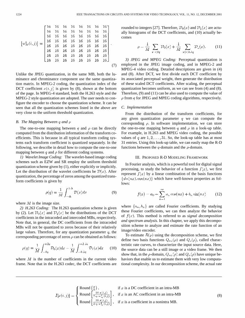
(7)
Unlike the JPEG quantization, in the same MB, both the lu-minance and chrominance component use the same quantiza-tion matrix. In MPEG-2 coding, the quantization index of theDCT coefficient is given by (8), shown at the bottomof the page. In MPEG-4 standard, both the H.263 style and theMPEG-2 style quantization are adopted. The user needs to con-figure the encoder to choose the quantization scheme. It can beseen that all the quantization schemes listed in the above arevery close to the uniform threshold quantization.
B. The Mapping Betweenand
The one-to-one mapping betweenand can be directlycomputed from the distribution information of the transform co-efficients. This is because in all typical transform coding sys-tems each transform coefficient is quantized separately. In thefollowing, we describe in detail how to compute the one-to-onemapping between and for different coding systems.
1) Wavelet Image Coding:The wavelet-based image codingschemes such as EZW and SR employ the uniform thresholdquantization scheme given by (1), either explicitly or implicitly.Let the distribution of the wavelet coefficients be . Afterquantization, the percentage of zeros among the quantized trans-form coefficients is given by
(9)
where is the image size.2) H.263 Coding: The H.263 quantization scheme is given
by (2). Let and be the distributions of the DCTcoefficients in the intracoded and intercoded MBs, respectively.Note that, in general, the DC coefficients from the intracodedMBs will not be quantized to zeros because of their relativelylarge values. Therefore, for any quantization parameter, thecorresponding percentage of zeroscan be obtained as follows:
(10)
where is the number of coefficients in the current videoframe. Note that in the H.263 codec, the DCT coefficients are
rounded to integers [27]. Therefore, and are actu-ally histograms of the DCT coefficients, and (10) actually be-comes
(11)
3) JPEG and MPEG Coding:Perceptual quantization isemployed in the JPEG image coding, and in MPEG-2 andMPEG-4 video coding. Detailed descriptions are given in (4)and (8). After DCT, we first divide each DCT coefficient byits associated perceptual weight, then generate the distributionof these scaled DCT coefficients. After scaling, the perceptualquantization becomes uniform, as we can see from (4) and (8).Therefore, (9) and (11) can be also used to compute the value of
from for JPEG and MPEG coding algorithms, respectively.
C. Implementation
From the distribution of the transform coefficients, forany given quantization parameter we can compute thecorresponding . In software implementation, we can storethe one-to-one mapping betweenand in a look-up table.For example, in H.263 and MPEG video coding, the possiblevalues of are . So, the look-up table has at most31 entries. Using this look-up table, we can easily map the R-Dfunctions between the-domain and the-domain.
III. PROPOSEDR-D MODELING FRAMEWORK
In Fourier analysis, which is a powerful tool for digital signalprocessing, to study the behavior of a function , we firstrepresent by a linear combination of the basis functions
which have well-known properties as fol-lows:
(12)
where are called Fourier coefficients. By studyingthese Fourier coefficients, we can then analyze the behaviorof . This method is referred to assignal decompositionand spectrum analysis. In this chapter, we apply this decompo-sition scheme to analyze and estimate the rate function of animage/video encoder.
To estimate using the decomposition scheme, we firstdefine two basis functions and , called charac-teristic rate curves, to characterize the input source data. Here,the source data can be a still image or a video frame. We thenshow that, in the -domain, and have unique be-haviors that enable us to estimate them with very low computa-tional complexity. In our decomposition scheme, the actual rate
Round if is a DC coefficient in an intra-MB
Round if is an AC coefficient in an intra-MB
Round if is a coefficient in a nonintra MB.
(8)

HE AND MITRA: A UNIFIED RATE-DISTORTION ANALYSIS FRAMEWORK FOR TRANSFORM CODING 1225
function is represented by a linear combination of and
(13)
where , , and are the rate decomposition coef-ficients. For a given input image, and are de-termined by their definitions. If we use different coding algo-rithms to encode this image, we should obtain different .According to (13), we know the corresponding decompositioncoefficients should also be different. In other words, differentcoding algorithms correspond to different decomposition coef-ficients. Therefore, we can say that modelthe coding algorithm, while characterize theinput source data. As mentioned above, the R-D performanceof a coding system is determined by these two components. Wesee that both of these components have been integrated by linearcombination into (13), which serves as the framework for our-domain source modeling. In Section IV, we define and
, analyze their properties, and discuss the rate decompo-sition scheme in detail.
IV. CHARACTERISTIC RATE CURVES
In [1], we have defined two characteristic rate curves,and , to describe the input source data for H.263 videocoding. In this work, we generalize their definitions for all typ-ical image/video transform coding systems. Based on our exten-sive simulations, we then show that they have unique statisticalproperties, which hold for any of these coding systems. We alsoprovide a theoretical justification for the unique properties. Withthese properties, a fast algorithm is proposed to estimate thesetwo rate curves.
A. Definition
The characteristic rate curves and are em-ployed to characterize the transform coefficients to be quan-tized and coded by the image/video encoder. Their definitionsare based on the binary representation of the nonzero coeffi-cients and the run length numbers of zeros. This is because, asexplained in [1], we believe that the binary representation col-lects the most valuable information about the R-D behavior ofthe transform coefficients. Based on the binary representation,we define and as follows.
Step 1) Conversion to 1-D array: After transform and quan-tization with a quantization parameter, the trans-form coefficients are rearranged into a 1-D array.If DWT is used, the subband coefficients are rear-ranged into in a raster scan order. If DCT is used,all the DCT coefficients are rearranged intoin azig–zag scan order inside each block and a block-wise raster scan order at the block level.
Step 2) Binary Representation: For any nonzero number,its size is defined as
(14)
which is exactly the number of bits for its sign-mag-nitude representation. Note that, according to theabove definition, is 2 instead of 1. For eachcontinuous string of zeros in, we count their runlength. Let be the sum of the sizes of all the runlength numbers. For all the nonzero transform coef-ficients in , we define
(15)
which is the sum of their sizes. Let
(16)
where is the number of coefficients inside the pic-ture. and can be respectively regarded asthe pseudo-coding bit rates for the nonzeros and zerocoefficients. Obviously, they are functions of. Let
be the percentage of zeros among the quantizedtransform coefficients. From Section II, we knowthat there is a one-to-one mapping betweenand. Therefore, mathematically, and are also
functions of , denoted by and , re-spectively. These two functions are called the char-acteristic rate curves.
We would like to point out one implementation detail aboutthis definition. In H.263 video coding, the DC coefficients fromthe intracoded MBs are quantized with a fixed quantization pa-rameter 8 and encoded with a fixed number of bits which is also8. This implies that the coding bit rate of these DC coefficients isfixed and does not depend on the quantization parameter. There-fore, when we scan the picture to form the 1-D array, the DCcoefficients from the intracoded MBs are all skipped. However,their coding bit rate will be compensated by our rate decompo-sition scheme presented in Section V.
B. Statistical Properties
In [1], we observed that the two characteristic rate curvesand have unique properties for H.263 video
coding. In this section, we show that these properties hold forall typical image/video transform coding systems.
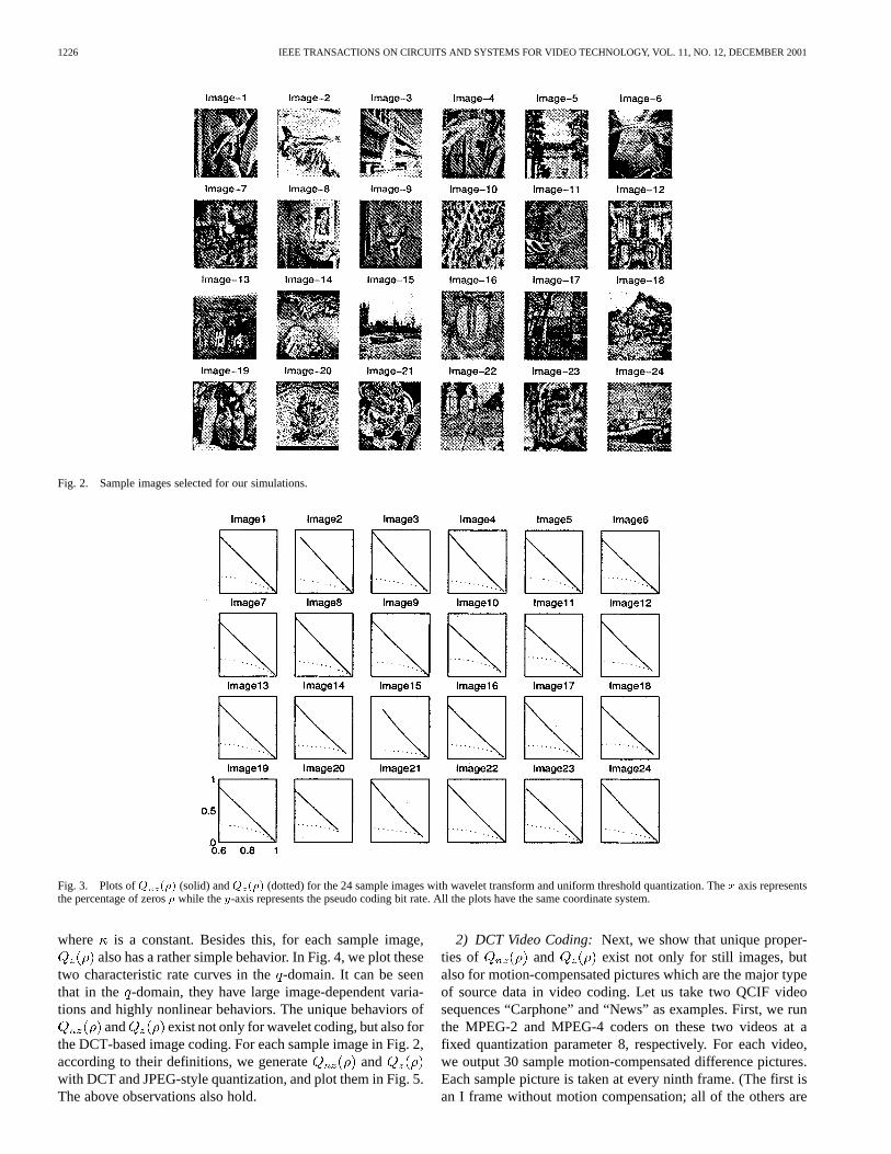
1) Still Image Coding:For each sample image in Fig. 2, wefirst decompose it with a 9–7 Debauchies wavelet [26]. Ac-cording to their definitions, we generate the rate curvesand and plot them in Fig. 3. Two observations can bemade from these plots. First, although the sample images arequite different from each other, their characteristic rate curvesshare the same pattern. The second observation is thatisapproximately a straight line. Note that whenis 1.0, whichmeans all the coefficients are quantized to zeros, by definition
is 0, i.e., must pass through the point .Hence, it has the following expression:
(17)
1226 IEEE TRANSACTIONS ON CIRCUITS AND SYSTEMS FOR VIDEO TECHNOLOGY, VOL. 11, NO. 12, DECEMBER 2001
Fig. 2. Sample images selected for our simulations.
Fig. 3. Plots ofQ (�) (solid) andQ (�) (dotted) for the 24 sample images with wavelet transform and uniform threshold quantization. Thex axis representsthe percentage of zeros� while they-axis represents the pseudo coding bit rate. All the plots have the same coordinate system.
where is a constant. Besides this, for each sample image,also has a rather simple behavior. In Fig. 4, we plot these
two characteristic rate curves in the-domain. It can be seenthat in the -domain, they have large image-dependent varia-tions and highly nonlinear behaviors. The unique behaviors of
and exist not only for wavelet coding, but also forthe DCT-based image coding. For each sample image in Fig. 2,according to their definitions, we generate andwith DCT and JPEG-style quantization, and plot them in Fig. 5.The above observations also hold.
2) DCT Video Coding:Next, we show that unique proper-ties of and exist not only for still images, butalso for motion-compensated pictures which are the major typeof source data in video coding. Let us take two QCIF videosequences “Carphone” and “News” as examples. First, we runthe MPEG-2 and MPEG-4 coders on these two videos at afixed quantization parameter 8, respectively. For each video,we output 30 sample motion-compensated difference pictures.Each sample picture is taken at every ninth frame. (The first isan I frame without motion compensation; all of the others are

HE AND MITRA: A UNIFIED RATE-DISTORTION ANALYSIS FRAMEWORK FOR TRANSFORM CODING 1227
Fig. 4. Plots ofQ (q) (solid) andQ (q) (dotted) for the 24 sample images with wavelet transform and uniform threshold quantization. Thex-axis representsthe quantization parameterq while they-axis represents the pseudo coding bit rate. All the plots have the same coordinate system.
Fig. 5. Plots ofQ (�) (solid) andQ (�) (dotted) for the 24 sample images with DCT and JPEG quantization. Thex axis represents the quantization parameterq, while they axis represents the pseudo coding bit rate. All the plots have the same coordinate system.
P frames.) We plot and for each sample picturefrom “Carphone” and “News” in Figs. 6 and 7, respectively. Itcan be seen that the unique properties of andalso exist in MPEG-2 and MPEG-4 video coding.
C. Justification of the Linearity of
The definition of is based on the pseudo coding of thenonzero transform coefficients, which is actually the sign-mag-nitude representation given by (14). From the simulation resultspresented in the above, we observe that it has a very interestinglinear behavior. In the following, we provide a theoretical justi-
fication for the linearity of . Note that the quantizationschemes employed in the typical transform coding systems areall essentially uniform threshold quantizers. Therefore, in thefollowing, we take the uniform threshold quantizer as an ex-ample to show the linearity of . It is well known that thetransform coefficients have a generalized Gaussian distributiongiven by
(18)

1228 IEEE TRANSACTIONS ON CIRCUITS AND SYSTEMS FOR VIDEO TECHNOLOGY, VOL. 11, NO. 12, DECEMBER 2001
Fig. 6. Plots ofQ (�) (solid line) andQ (�) (dash–dot line) for the 30 sample difference pictures from “Carphone” coded by MPEG-2. Thex axis representsthe percentage of zeros�. All the subplots have the same coordinate system as the one at the bottom-left corner.
Fig. 7. Plots ofQ (�) (solid line) andQ (�) (dash–dot line) for the 30 sample difference pictures from “News” coded by MPEG-4. Thex axis represents thepercentage of zeros�. All the subplots have the same coordinate system as the one at the bottom-left corner.
where
(19)
Here, is the standard deviation of the transform coefficients,and is a model parameter which controls the shape of the dis-tribution. For example, when and 1.0, becomes
Gaussian and Laplacian distributions, respectively. Accordingto (15), for any given quantization step size, we have
(20)
where
(21)
HE AND MITRA: A UNIFIED RATE-DISTORTION ANALYSIS FRAMEWORK FOR TRANSFORM CODING 1229
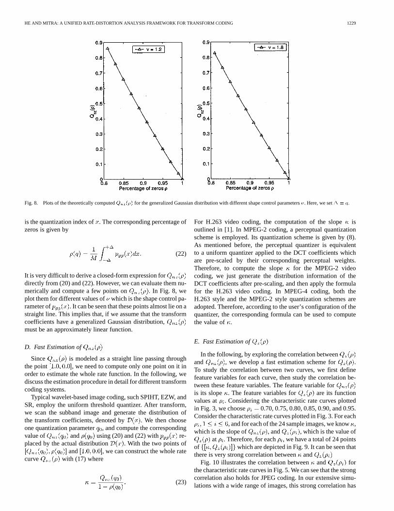
Fig. 8. Plots of the theoretically computedQ (�) for the generalized Gaussian distribution with different shape control parameters�. Here, we set� = q.
is the quantization index of. The corresponding percentage ofzeros is given by
(22)
It is very difficult to derive a closed-form expression fordirectly from (20) and (22). However, we can evaluate them nu-merically and compute a few points on . In Fig. 8, weplot them for different values of which is the shape control pa-rameter of . It can be seen that these points almost lie on astraight line. This implies that, if we assume that the transformcoefficients have a generalized Gaussian distribution,must be an approximately linear function.
D. Fast Estimation of
Since is modeled as a straight line passing throughthe point , we need to compute only one point on it inorder to estimate the whole rate function. In the following, wediscuss the estimation procedure in detail for different transformcoding systems.
Typical wavelet-based image coding, such SPIHT, EZW, andSR, employ the uniform threshold quantizer. After transform,we scan the subband image and generate the distribution ofthe transform coefficients, denoted by . We then chooseone quantization parameter, and compute the correspondingvalue of and using (20) and (22) with re-placed by the actual distribution . With the two points of
and , we can construct the whole ratecurve with (17) where
(23)
For H.263 video coding, the computation of the slopeisoutlined in [1]. In MPEG-2 coding, a perceptual quantizationscheme is employed. Its quantization scheme is given by (8).As mentioned before, the perceptual quantizer is equivalentto a uniform quantizer applied to the DCT coefficients whichare pre-scaled by their corresponding perceptual weights.Therefore, to compute the slope for the MPEG-2 videocoding, we just generate the distribution information of theDCT coefficients after pre-scaling, and then apply the formulafor the H.263 video coding. In MPEG-4 coding, both theH.263 style and the MPEG-2 style quantization schemes areadopted. Therefore, according to the user’s configuration of thequantizer, the corresponding formula can be used to computethe value of .
E. Fast Estimation of
In the following, by exploring the correlation betweenand , we develop a fast estimation scheme for .To study the correlation between two curves, we first definefeature variables for each curve, then study the correlation be-tween these feature variables. The feature variable foris its slope . The feature variables for are its functionvalues at . Considering the characteristic rate curves plottedin Fig. 3, we choose 0.70, 0.75, 0.80, 0.85, 0.90, and 0.95.Consider the characteristic rate curves plotted in Fig. 3. For each
, and for each of the 24 sample images, we know,which is the slope of , and , which is the value of
at . Therefore, for each , we have a total of 24 pointsof which are depicted in Fig. 9. It can be seen thatthere is very strong correlation betweenand
Fig. 10 illustrates the correlation betweenand forthe characteristic rate curves in Fig. 5. We can see that the strongcorrelation also holds for JPEG coding. In our extensive simu-lations with a wide range of images, this strong correlation has

1230 IEEE TRANSACTIONS ON CIRCUITS AND SYSTEMS FOR VIDEO TECHNOLOGY, VOL. 11, NO. 12, DECEMBER 2001
Fig. 9. Linear correlation between� and the valuesQ (� ) at 0.70, 0.75, 0.80, 0.85, 0.90, and 0.95 with wavelet transform.
Fig. 10. Linear correlation between� and the valuesQ (� ) at 0.70, 0.75, 0.80, 0.85, 0.90, and 0.95 with DCT.
been found to exist in all cases. Therefore, we have the followinglinear correlation model:
(24)
which can be employed to estimate . The coefficientsand are obtained by statistical regression and the corre-
sponding linear model is also plotted in Figs. 9 and 10. Basedon (24), we can estimate six points on . If necessary,the whole rate curve can be constructed by linear interpolation.In [1], a cubic correlation model is employed for H.263 videocoding. The correlation models for MPEG-2 and MPEG-4 videocoding can also be obtained in the same way.
V. RATE CURVE DECOMPOSITION
In Section IV, we have defined two rate curves andto characterize the input source data, and proposed a
fast algorithm to estimate them. According to our decompo-sition and analysis scheme, the actual rate curve in the-do-main is represented by a linear combination of and
, as shown in (13), where the coding algorithm is mod-eled by the decomposition coefficients . Inthe following, we take the JPEG coding algorithm as an ex-ample to explain how to determine the decomposition coeffi-cients for a specific coding algorithm.

HE AND MITRA: A UNIFIED RATE-DISTORTION ANALYSIS FRAMEWORK FOR TRANSFORM CODING 1231
A. Decomposition Coefficients
For the 24 sample images shown in Fig. 2, with the fast algo-rithms developed in Section IV, we can estimate the values of
and where , . Byrunning the JPEG coding algorithm at different quantization pa-rameters, we can generate some points on its actual rate curve
. With interpolation, we can obtain .According to (13), we should have
(25)
The values of are obtained by linear re-gression over the sample data for the24 sample images. The decomposition coefficients for the JPEGcoding algorithm are listed in Table I. Following the same pro-cedure, we can also obtain the decomposition coefficients forother coding algorithms, such as EZW, SPIHT, SR, MPEG-2,and MPEG-4. Once they are obtained, they are fixed during theactual rate curve estimation process. In practice, to improve themodeling accuracy, we can also update the decomposition coef-ficients after a certain number of frames are coded.
VI. L INEAR RATE REGULATION
Using the characteristic rate curves and the rate curve decom-position scheme introduced in Sections IV and V, we can esti-mate six points on the rate curve . The whole rate curve canbe then obtained by linear interpolation. To further improve theestimation accuracy and robustness, we propose the followinglinear rate regulation scheme.
In our previous work [22], based on extensive experimentalresults, we have shown that in any typical image/video trans-form coding system, the actual coding rate function in the-do-main is approximately a linear function. In other words,we have the following linear rate model
(26)
This rate model is very accurate because it is derived from theactual coding results. The only parameter of the rate model is theslope . Within the context of video coding, we can estimate thevalue of from the coding statistics of previous video frame orMBs. However, in still image coding, we only have one image.In other words, there is no previous image with similar statisticsavailable. Furthermore, typical still image coding algorithms,such as EZW, SPIHT, SR, and JPEG image coding, do not useadaptive quantization. In other words, the quantization of eachtransform coefficient is nonadaptive and does not depend on thequantization of its preceding coefficients. The quantization ofall transform coefficients is controlled only by the picture quan-tization step size. The lack of the coding statistics of previousdata and the nonadaptive quantization scheme make it very diffi-cult to estimate the value of. Therefore, the linear rate model in(26) can not be directly used to estimate the rate function beforequantization and coding. However, (26) indicates that the ratecurve estimated by Sections IV and V should be a linear func-tion. In other words, the estimated six pointsshould lie on a straight line. (Because of the source modeling
TABLE IDECOMPOSITIONCOEFFICIENTSA(�), B(�), AND C(�) AT � FOR THE
JPEG CODING ALGORITHM
error, this is often not the case.) Therefore, We can utilize thislinear constraint to remove the source modeling error signifi-cantly. This procedure is calledlinear rate regulation.
The linear rate regulation operates as follows. From, we first estimate the slope and then
construct using the linear rate model in (26). Accordingto the linear regression theorem, the optimum estimation ofis given by
(27)
According to the linear rate model, the estimated rate curveafter linear regulation is then given by
(28)
VII. U NIFIED R-D CURVE ESTIMATION ALGORITHM
Based on the fast estimation of and , the ratecurve decomposition, and the linear rate regulation, a unifiedR-D curve estimation algorithm for all typical transform-codingsystems is proposed as follows.
Step 1) Generation of the Distribution: After applying ei-ther the DWT or the DCT transform, generate thedistribution of the transform coefficients. Note thatthe transform coefficients are real numbers. We canapproximate their distribution by the histogram oftheir integer parts. In the implementation of standardvideo coding such as MPEG and H.263, the DCT co-efficients automatically have integer values. In thiscase, no approximation is needed. Depending on thespecific quantization scheme, the distribution gen-eration process varies. For example, in H.263, thedistributions of the intracoded and intercoded MBsneed to be stored separately. In JPEG and MPEGcoding, we need to generate the distribution afterpre-scaling of the DCT coefficients, as described inSection IV. Based on the distributions of the trans-form coefficients, the one-to-one mapping lookuptable between and is obtained as discussed inSection II.

1232 IEEE TRANSACTIONS ON CIRCUITS AND SYSTEMS FOR VIDEO TECHNOLOGY, VOL. 11, NO. 12, DECEMBER 2001
Fig. 11. Six test images for the evaluation of the proposed R-D estimation algorithm when applied to the SPIHT and SR encoders.
Step 2) Estimate and : Choose one quantiza-tion parameter and compute the corresponding
and as discussed in Section IV-D.The slope of is obtained by (23). The valueof at is given by
(29)
With the linear correlation model in (24), the valueof is determined.
Step 3) Rate Curve Estimation: With (25), compute .After linear regulation, the estimated rate curveis given by (28). With the- mapping lookup table,
is mapped into the-domain to obtain .
Step 4) Compute Distortion Curve: In typical image/videotransform coding, each coefficient is quantized inde-pendently, the overall distortion is exactly the sum-mation of the distortion at each coefficient. There-fore, the D-Q curve can be directly computedfrom the distribution information.
We can see that, in the proposed algorithm, the major com-putation is to generate the distribution of the transform coeffi-cients. The remaining computation involves only a few additionand multiplication operations that are carried out on the distribu-tion. Compared to the complexity of the whole coding process,the overall complexity of the proposed estimation algorithm isvery low. We can see that the R-D curves are estimated beforequantization and coding.
VIII. E XPERIMENTAL RESULTS
In this section, we apply the algorithm presented in Sec-tion VII to estimate the R-D curves for transform coding ofstill images and videos. Based on the estimated R-D functions,
we can then control the output bit rate or picture quality of theencoder.
A. Application in Still Image Coding
The proposed estimation algorithm has been applied to theSPIHT and the SR encoders. We arbitrarily choose six test im-ages as shown in Fig. 11. The estimated R-D curves and the ac-tual ones for SR and SPIHT coding are shown in Figs. 12 and 13,respectively. It can be seen that the estimated R-D curves arevery close to the actual ones curves.
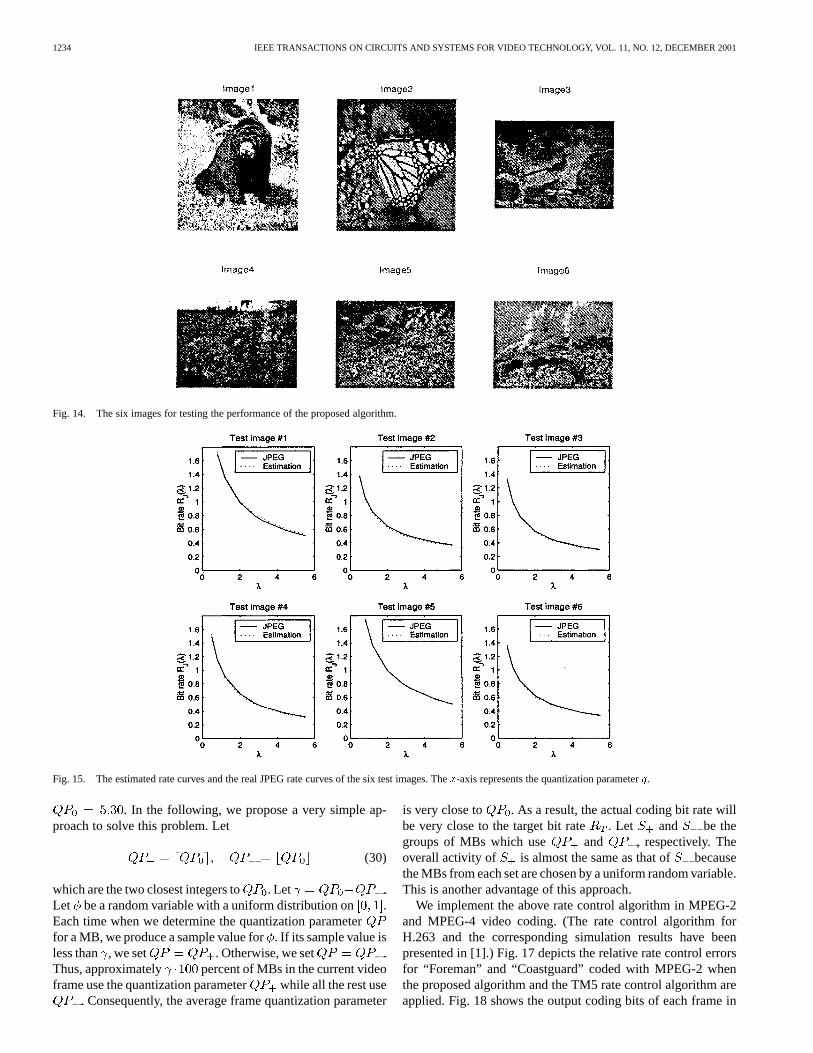
The R-D estimation algorithm is also applied to JPEG codingof still images. The six test images with a wide range of R-Dcharacteristics are shown in Fig. 14. We apply the proposed es-timation algorithm to estimate their rate curves. The estimatedrate curves and the actual curves are plotted in Fig. 15. The rel-ative estimation errors of the rate curve at , 0.8,1.2, 2.0, 2.8, 3.2, 4.5, and 5.5 for each test image are listed inTable II. The estimation errors are very small, mostly less than2% in their absolute values. Table III shows the relative esti-mation errors without linear rate regulation. Clearly, we can seethat linear rate regulation significantly improves the estimationaccuracy and robustness.
B. Application in DCT Video Coding
We next show that the proposed R-D estimation algorithmalso works very well for DCT-based video coding. Based on theestimated R-D functions of each video frame, we can then con-trol the output bit rate of the video encoder. We first show that,for a given MC difference video frame, the proposed algorithmcan accurately estimate its R-D function. To this end, we runthe MPEG-4 codec on the “Carphone” QCIF video sequence at
and output the 10-th and 70-th MC difference frames.Using the algorithm presented in Section VII, we estimate theirR-D curves and compare them with the actual ones generated

HE AND MITRA: A UNIFIED RATE-DISTORTION ANALYSIS FRAMEWORK FOR TRANSFORM CODING 1233
Fig. 12. R-D curve-estimation results for the SR coding system.
Fig. 13. R-D curve-estimation results for the SPIHT coding system.
by the MPEG-4 codec in Fig. 16. It can be seen that the R-Destimation is very accurate.
C. Frame-Level Rate Control Algorithm
WiththeestimatedR-Dfunctions,wecanthendevelopaframe-level rate control algorithm for DCT video coding. The rate con-trol process consists of the following major steps. In the first step,the target bit rate of the current video frame is determined ac-cording to the channel bandwidth and buffer status, as explainedin [1], [14]. In the second step, based on estimated the rate curve
, the frame quantization parameter can be determined
to achieve the target bit rate . Obviously, satisfies, where is the estimated R-Q function. We see that
this rate control algorithm operates at the frame level.It should be noted that, in standard video encoders, the quan-
tization parameter should have an integer value between 1 and31 [4]–[6]. However, the frame quantization parameter ob-tained in the frame-level rate control algorithm is a real number.For example, could be 5.30. If we round to its nearestinteger 5 and use it for the quantization parameter for each MBin the current frame, the actual coding bitwill be quite dif-ferent from the target bit rate , which is actually achieved by
1234 IEEE TRANSACTIONS ON CIRCUITS AND SYSTEMS FOR VIDEO TECHNOLOGY, VOL. 11, NO. 12, DECEMBER 2001
Fig. 14. The six images for testing the performance of the proposed algorithm.
Fig. 15. The estimated rate curves and the real JPEG rate curves of the six test images. Thex-axis represents the quantization parameterq.
. In the following, we propose a very simple ap-proach to solve this problem. Let
(30)
which are the two closest integers to . Let .Let be a random variable with a uniform distribution on .Each time when we determine the quantization parameterfor a MB, we produce a sample value for. If its sample value isless than , we set . Otherwise, we set .Thus, approximately percent of MBs in the current videoframe use the quantization parameter while all the rest use
. Consequently, the average frame quantization parameter
is very close to . As a result, the actual coding bit rate willbe very close to the target bit rate . Let and be thegroups of MBs which use and , respectively. Theoverall activity of is almost the same as that of becausethe MBs from each set are chosen by a uniform random variable.This is another advantage of this approach.
We implement the above rate control algorithm in MPEG-2and MPEG-4 video coding. (The rate control algorithm forH.263 and the corresponding simulation results have beenpresented in [1].) Fig. 17 depicts the relative rate control errorsfor “Foreman” and “Coastguard” coded with MPEG-2 whenthe proposed algorithm and the TM5 rate control algorithm areapplied. Fig. 18 shows the output coding bits of each frame in

HE AND MITRA: A UNIFIED RATE-DISTORTION ANALYSIS FRAMEWORK FOR TRANSFORM CODING 1235
TABLE IIRELATIVE ESTIMATION ERROR FORJPEG CODING OF THETEST IMAGES
FIG. 14—WITH LINEAR RATE REGULATION
TABLE IIIRELATIVE ESTIMATION ERROR FORJPEG CODING OF THETEST IMAGES
FIG. 14—WITHOUT LINEAR RATE REGULATION
Fig. 16. R-D estimation results for Frames 10 and 70 in “Carphone” QCIFvideo coded by MPEG-4.
“News” QCIF video sequence coded by MPEG-4. (It shouldbe noted that in this experiment, the whole scene is coded asone object.) It can be seen that with the proposed rate controlalgorithm, the actual output bit rate is more accurately matchedto the bit’s target.
Compared to other rate control algorithms, such as the TM5,TMN8, and VM8 algorithms, the proposed algorithm has the
Fig. 17. The relative rate control error (in percentage) of each frame of“Foreman” and “Coastguard” coded with MPEG-2 when the proposed ratecontrol algorithm and the TM5 algorithm are applied.
Fig. 18. The output coding bits of each frame in “News” coded with MPEG-4when the proposed rate control algorithm and the VM8 algorithm are applied.
following advantages. First, our algorithm operates at the framelevel, which implies the rate control procedure only needs toperform once per frame. However, in the MB-level TM5 andTMN8 rate control algorithms, after each MB is coded, the al-gorithm has to update its model parameters, which inherently in-creases the computational complexity. Second, based on the es-timated R-D functions, the proposed algorithm select the meanquantization parameter for the current frame. In this way, thewhole frame is almost uniformly quantized. However, in theTM5 and TMN8 rate control algorithms, the quantization pa-rameter for each MB is adaptively selected based on the currentcoding statistics. In this way, inside one frame, the quantiza-tion settings of each MB is different (sometimes, quite different)from others. As a result, this often degrades the overall visualquality, as explained in [1]. Finally, unlike other rate control al-gorithms, the proposed algorithm performs the rate estimationand control for each frame independently. Therefore, it does notsuffer from performance degradation at scene changes at all.

1236 IEEE TRANSACTIONS ON CIRCUITS AND SYSTEMS FOR VIDEO TECHNOLOGY, VOL. 11, NO. 12, DECEMBER 2001
IX. CONCLUDING REMARKS
By introducing the concepts of characteristic rate curve andrate curve decomposition, a generic framework for source mod-eling has been developed for all typical transform coding sys-tems. We have provided a theoretical justification for the uniqueproperty of the characteristic rate curves. A linear rate regulationscheme has also been proposed to improve the modeling accu-racy and robustness. Based on this source modeling framework,a unified R-D estimation and control algorithm is proposed forimage and video coding. There are two major contributions ofthis work. First, we present a novel methodology for R-D anal-ysis. Compared to the conventional analytic R-D formulation, itis much more accurate. Compared to the operational R-D com-putation method, it has much lower complexity. The second con-tribution of this work is the unified R-D estimation and controlalgorithm, which outperforms other rate control algorithms interms of control accuracy and robustness.
REFERENCES
[1] Z. He, Y. K. Kim, and S. K. Mitra, “Low-delay rate control for DCTvideo coding via�-domain source modeling,”IEEE Trans. Circuits Syst.Video Technol., vol. 11, pp. 928–940, Aug. 2001.
[2] G. K. Wallace, “The JPEG still picture compression standard,”Commun.ACM, vol. 34, pp. 30–44, Apr. 1991.
[3] M. W. Marcellin, M. J. Gormish, A. Bilgin, and M. P. Boliek, “Anoverview of JPEG-2000,” inProc. DCC 2000, Snowbird, UT, Mar.2000, pp. 523–541.
[4] D. LeGall, “MPEG: A video compression standard for multimedia ap-plication,” Commun. ACM, vol. 34, pp. 46–58, April 1991.
[5] “Video Coding for Low Bit Rate Communications,” ITU-T, ITU-T Rec-ommendation H.263, version 1, 1995.
[6] T. Sikora, “The MPEG-4 video standard verification model,”IEEETrans. Circuits Syst.Video Technol., vol. 7, pp. 19–31, Feb. 1997.
[7] J. M. Shapiro, “Embedded image coding using zero-trees of wavelet co-efficients,”IEEE Trans. Signal Processing, vol. 41, pp. 3445–3462, Dec.1993.
[8] A. Said and W. A. Pearlman, “A new fast and efficient image codec basedon set partitioning in hierarchical trees,”IEEE Trans. Circuits Syst.VideoTechnol., vol. 6, pp. 243–250, June 1996.
[9] M. J. Tsai, J. D. Villasenor, and F. Chen, “Stack-run image oding,”IEEETrans. Circuits Syst.Video Technol., vol. 6, pp. 519–521, Oct. 1996.
[10] H. Gish and J. N. Pierce, “Asymptotically efficient quantizing,”IEEE.Trans. Inform. Theory, vol. IT-14, pp. 676–683, Sept 1968.
[11] T. Berger,Rate Distortion Theory. Englewood Cliffs, NJ: Prentice-Hall, 1984.
[12] H. -M. Hang and J. -J. Chen, “Source model for transform video coderand its application – part I: Fundamental theory,”IEEE Trans. CircuitsSyst.Video Technol., vol. 7, pp. 287–298, Apr. 1997.
[13] I. H. Witten, R. M. Neal, and J. G. Cleary, “Arithmetic coding for datacompression,”Commun. ACM, vol. 30, pp. 520–540, June 1996.
[14] J. Ribas-Corbera and S. Lei, “Rate control in DCT video coding forlow-delay communications,”IEEE Trans. Circuits Syst.Video Technol.,vol. 9, pp. 172–185, Feb. 1999.
[15] W. Ding and B. Liu, “Rate control of MPEG video coding andrecording by rate-quantization modeling,”IEEE Trans. CircuitsSyst.Video Technol., vol. 6, pp. 12–20, Feb. 1996.
[16] T. Chiang and Y. -Q. Zhang, “A new rate control scheme using quadraticrate distortion model,”IEEE Trans. Circuits Syst.Video Technol., vol. 7,pp. 246–250, Feb. 1997.
[17] Y. Shoham and A. Gersho, “Effcient bit allocation for an arbitrary setof quantizers,”IEEE Trans. Acoust., Speech, Signal Processing, vol. 36,pp. 1445–1453, Sept. 1988.
[18] K. Ramchandran and M. Vetterli, “Rate-distortion optimal fast thresh-olding with complete JPEG/MPEG decoder compatibility,”IEEE Trans.Image Processing, vol. 3, pp. 700–704, Sept. 1994.
[19] MPEG-2 Video Test Model 5, ISO/IEC JTC1/SC29/WG11MPEG93/457, 1993.
[20] J. Ribas-Corbera and S. Lei, “Contribution to the rate control Q2 exper-iment: A quantizer control tool for achieving target bit rates accurately,”in Coding of Moving Pictures and Associated Audio MPEG96/M1812ISO/IEC JTC/SC29/WG11Sevilla, Spain, 1997.
[21] Video Group, “Text of ISO/IEC 14 496-2 MPEG4 video VM—Version8.0,” ISO/IEC JTC1/SC29/WG11 Coding of Moving Pictures and As-sociated Audio MPEG 97/W1796, Stockholm, Sweden, 1997.
[22] Z. He, Y. Kim, and S. K. Mitra, “A novel linear source model and aunified rate control algorithm for H.263/MPEG-2/MPEG-4,” inProc.Int. Conf. Acoustics, Speech, and Signal Processing, Salt Lake City, UT,May 2001.
[23] L.-J. Lin and A. Ortega, “Bit-rate control using piecewise approxi-mated rate-distortion characteristics,”IEEE Trans. Circuits Syst.VideoTechnol., vol. 38, pp. 82–93, Jan. 1990.
[24] E. D. Frimout, J. Biemond, and R. L. Lagendik, “Forward rate controlfor MPEG recording,” inProc. SPIE Visual Commun. Image Processing,Cambridge, MA, Nov. 1993, pp. 184–194.
[25] A. Y. K. Yan and M. L. Liou, “Adaptive predictive rate control algorithmfor MPEG videos by rate quantization method,” inProc. Picture CodingSymposium, Berlin, Germany, Sept. 1997, pp. 619–624.
[26] M. Antonini, M. Barlaud, P. Mathieu, and I. Daubechies, “Image codingusing wavelet transform,”IEEE Trans. Image Processing, vol. 1, pp.205–220, Apr. 1992.
[27] Telenor codec, “ITU-T/SG-15, video codec test model, TMN5,” TelenorResearch, 1995.
[28] E. Y. Lam and J. W. Goodman, “A mathematical analysis of the DCT co-efficient distributions for images,”IEEE Trans. Image Processing, vol.9, pp. 1661–1666, Oct. 2000.
[29] MoMuSys codec, “MPEG4 verification model version 7.0 ,” ISO/IECJTC1/SC29/WG11 Coding of Moving Pictures and Associated AudioMPEG97, Bristol, U.K, 1997.
Zhihai He (M’01) received the B.S. degree fromBeijing Normal University, Beijing, China, in 1994,and the M.S. degree from the Institute of Computa-tional Mathematics, Chinese Academy of Sciences,Beijing, China, in 1997, both in mathematics, andthe Ph.D. degree in electrical engineering from theUniversity of California at Santa Barbara in 2001.
He joined Sarnoff Corporation, Princeton, NJ, as aMember of Technical Staff. His current research in-terests include video coding and communication.
Sanjit K. Mitra (S’59–M’63–SM’69–F’74–LF’00)received the B.Sc. (Hons.) degree in physics in 1953from Utkal University, Cuttack, India, the M.Sc.(Tech.) degree in radio physics and electronics fromCalcutta University, Calcutta, India, in 1956, theM.S. and Ph.D. degrees in electrical engineeringfrom the University of California at Berkeley in 1960and 1962, respectively, and an Honorary Doctorateof Technology degree from the Tampere Universityof Technology, Tampere, Finland.
From 1962 to 1965, he was with Cornell Univer-sity, Ithaca, NY, as an Assistant Professor of Electrical Engineering. He was withthe AT&T Bell Laboratories, Holmdel, NJ, from June 1965 to January 1967. Hehas been on the faculty of the University of California since 1967, serving as aProfessor of Electrical and Computer Engineering since 1977 and Chairman ofthe Department from July 1979 to June 1982. He has published over 500 paperson signal and image processing, 11 books, and holds five patents.
Dr. Mitra served as the President of the IEEE Circuits and Systems (CAS) So-ciety in 1986 and as a Member-at-Large of the Board of Governors of the IEEESignal Processing (SP) Society from 1996-1999. He is currently a member ofthe editorial boards ofMultidimensional Systems and Signal Processing, SignalProcessing, Journal of the Franklin Institute, andAutomatika. He is the recipientof numerous awards, including the 1973 F.E. Terman Award, the 1985 AT&TFoundation Award of the American Society of Engineering Education, the Ed-ucation Award of the IEEE CAS Society in 1989, the Distinguished Senior U.S.Scientist Award from the Alexander von Humboldt Foundation of Germany in1989, the Technical Achievement Award of the IEEE SP Society in 1996, theMac Van Valkenburg Society Award, and the CAS Golden Jubilee Medal of theIEEE CAS Society in 1999, and the IEEE Millennium Medal in 2000. He is anAcademician of the Academy of Finland, a Fellow of the AAAS and SPIE, anda member of EURASIP and ASEE.