a unified graphical representation and tool for design and ...€¦ · 1 a unified graphical...
TRANSCRIPT

1
A Unified Graphical Representation and Tool for Design and Integration of Components in Heterogeneous Distributed Real-Time Systems
Hugo Andrade, John Breyer, Gerardo Garcia, Jacob Kornerup
National Instruments CorporationAustin, TX, USA

2
National Instruments
Distributors
Direct Sales Offices
7 Years• 30 Year Leaders in Computer-Based
Measurement and Automation• 3800 Employees, 1,500 Engineers• Corporate Headquarters in Austin,
Texas– Direct Operations in 40 Countries
• Over 600 Alliance Partners

3
Virtual Instrumentation Vision
“To do for test and measurement what the spreadsheet did for financial analysis.”

4
Use Case: Distributed Fly-by-Wire HIL Simulation• Challenge
– Integrate 10 distributed nodes executing device models
– Share simulation data and I/O with low latency
• Solution– Implement simulation models on
real-time platforms – Deterministic network used to
share data

5
Use Case: Engine HIL Simulation• Challenge: Simulate a 12 cylinder hybrid engine to
test control strategies• Solution: Implement simulation model on real-time
platform
Engine Control Unit (ECU)
6
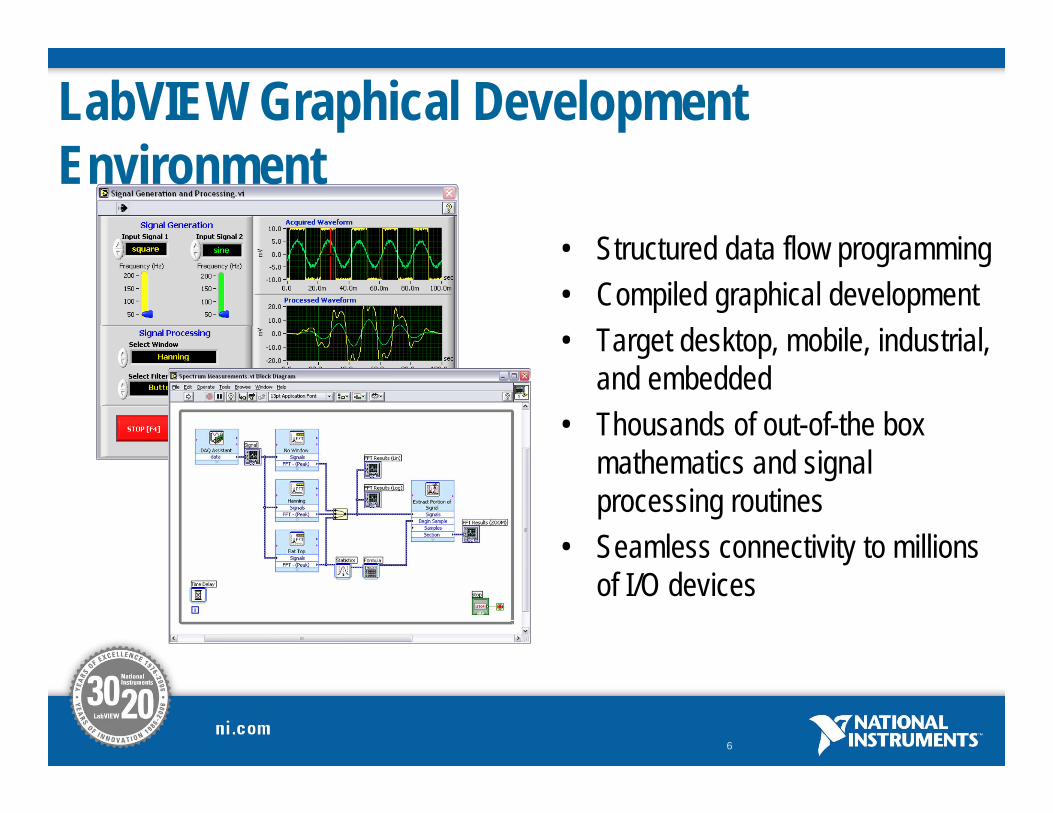
• Structured data flow programming• Compiled graphical development • Target desktop, mobile, industrial,
and embedded• Thousands of out-of-the box
mathematics and signal processing routines
• Seamless connectivity to millions of I/O devices
LabVIEW Graphical Development Environment

7
LabVIEW Platforms
Portable
FPGA
Embedded Controllers
PC
Handheld
Industrial Controllers (PXI)
Sensor
Vision System
LabVIEW
DSP/MPU

8

State Diagram
Real-Time FPGADistributed
Textual Math Simulation Configuration
C Code Generation

10
LabVIEW Shared Variable• Exchanging values when data flow is not appropriate
– Loop to Loop– In a distributed setting– Utilize non-blocking buffers

11
Timed Loop in LabVIEW: Specifying a Task
External Timing Source
(What makes me tick)
Configuration(What can I do for you)
Run Time Status(How am I doing)
Run Time Configuration(How can I serve you better)
Final Status(How did I do)

12
National Instruments’ Time-Triggered Network• Deterministic communication
– 100 µs to 100 ms network loop rates– ±5 µs clock synchronization between nodes
• Off-the-shelf hardware– Uses second Ethernet interface
• Communication across private network– Traffic is scheduled
• Similar to other time-triggered offerings– FlexRay, TTP, TTCAN, Ethernet PowerLink,
…

13
Using Deterministic Ethernet
• User specifies a network cycle time– All traffic is repeated at this interval
• Time-triggered variables– Used on the diagram just like other variables in LabVIEW
• Owning system is the only writer
– Values are communicated during designated time slots within the network cycle

14
Using Deterministic Ethernet • Network timing sources
– Fires the Timed Loop when the network event happens– Timing source types
• Network synchronized microsecond• Shared memory block has been reflected• Slot based variable timing sources

15
Other uses of shared variable
• Publish and subscribe• Non-blocking FIFOs• Streaming• DMA transfers• IO abstraction• Can you change the model of computation just by changing
variable types?– Without redrawing the diagram

16
Time-Triggered Distributed Simulation Use Case
• Separate models for different system components
• Models execute in real-time with synchronized timing
• Capability to switch to real-world I/O
Ethernet
Engine Model
EthernetReal-Time
I/O
RPM, Throttle
Timing, Fueling
Private Ethernet Network
ECU
RPM, Throttle
Timing, Fueling
Ethernet
Engine Model
Ethernet
ECU Model
RPM, Throttle
Timing, Fueling
Private Ethernet Network

17
• Create Time-Triggered Shared Variables
• Reserve time slots for variables in network configuration utility
Time-Triggered Distributed Simulation Example

18
Time-Triggered Distributed Simulation Example
RealECU

19
Capturing the Real-time Behavior

20
Separation of Concerns
• Programming abstractions– Diagram describes (abstract) functionality– Variable describes communication style– Timing sources describes events
• System architecture– Platform/ hw architecture
• Real-time, FPGA, Embedded, Desktop– Data transfer– Time, event, data triggering– HW/SW boundary

21
Temporal Isolation
• Static schedule of communication• Rigid temporal contract between programs and network
– Between components– Network enforces the global schedule
• If a program runs over, its values will not get communicated in this cycle

22
Questions