a tutorial for mplab ide and isis simulation 1 ...ece336.cankaya.edu.tr/uploads/files/introduction...
TRANSCRIPT
A TUTORIAL FOR MPLAB IDE AND ISIS SIMULATION
Aim of this tutorial is to show how to use MPLAB IDE and ISIS simulator. Tutorial
covers an object that writing a code to light a LED is tied to the 0th bit of PORTB. In this way,
PORTB in PIC16F84A should be set as an output port. After showing how to open a project
and how to write an assembly code in MPLAP IDE at part one, an ISIS simulation will be done
at part two.
1. Introduction to MPLAB IDE
1) Open MPLAP IDE. Icon of the editor can be seen in Figure-1.
Figure-1
2) From the “Project” choose “Project Wizard”, Figure-2.
Figure-2
3) Click “Next” in the Figure-3 window.

Figure-3
4) Select the device. In our case choose “PIC16F84A” and click “Next”.
Figure-4
5) Choose programming language. If you want to use Assembly choose “MPASM
Assembler” in the Figure-5, then click “Next”.
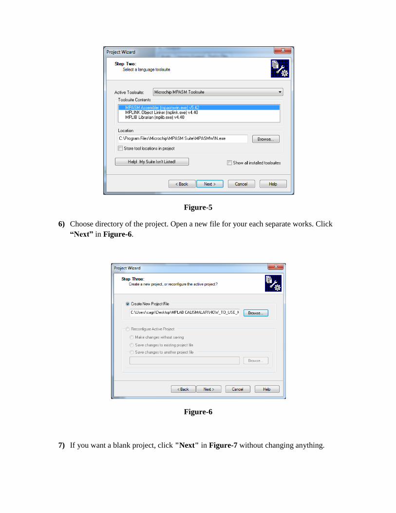
Figure-5
6) Choose directory of the project. Open a new file for your each separate works. Click
“Next” in Figure-6.
Figure-6
7) If you want a blank project, click "Next" in Figure-7 without changing anything.
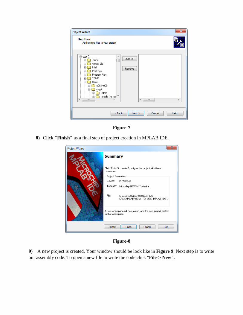
Figure-7
8) Click "Finish" as a final step of project creation in MPLAB IDE.
Figure-8
9) A new project is created. Your window should be look like in Figure 9. Next step is to write
our assembly code. To open a new file to write the code click "File-> New".

Figure-9
10) After writing your assembly code, it should be saved. Save the file by clicking floppy disk
icon in the menu. As it seen in the Figure-10, it should be saved in ".asm" file format which
means that this file should be compiled as an assembly file.
Figure-10

11) After saving code, it will be colored. Special commands are colored as blue and keywords
are colored as magenta in Figure-11.
Figure-11
12) Next step is to add assembly file,”main.asm”, to the project. Right click the "Source
Files" and then left click the "Add Files".
Figure-12

13) Assembly file is added to the project. Next step is to build it in order to see whether there
are errors or not. In the menu, press "build all" like shown in the Figure-13. Then in the next
window press "Absolute".
Figure-13
14) If your code is correct in terms of assembly syntax rules then "BUILD SUCCEEDED"
should be seen in the Output window of the project, Figure-14. After this step, ".hex" file is
created and we are ready for the simulation.
Figure-14
2. Simulate your assembly code in ISIS
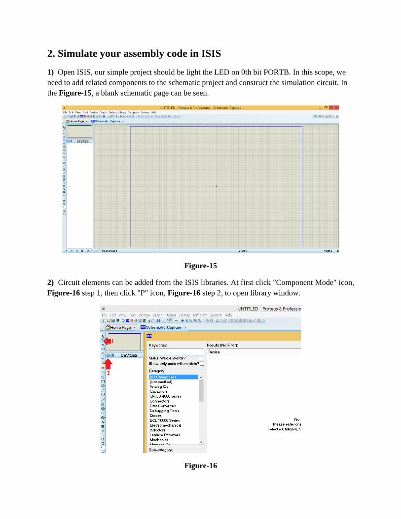
1) Open ISIS, our simple project should be light the LED on 0th bit PORTB. In this scope, we
need to add related components to the schematic project and construct the simulation circuit. In
the Figure-15, a blank schematic page can be seen.
Figure-15
2) Circuit elements can be added from the ISIS libraries. At first click "Component Mode" icon,
Figure-16 step 1, then click "P" icon, Figure-16 step 2, to open library window.
Figure-16

3) Type PIC16F84A, LED-RED, RES step by step then double click for each one. By doing
this, these components will be added to the current ISIS project. Figure-17 shows the operation.
Figure-17
4) As it seen in the Figure-18, circuit for the simulation of our assembly code is constructed.
GND object has been taken from "Terminals Mode" part. It is important to mention that, OSC
pins and MCLR pin are left floating. In the simulation, there is no need to add them however,
they should be used while constructing the circuit on breadboard or PCB.
Figure-18
5) Circuit is constructed, now we need to load our ".hex" file to the PIC and run the simulation.
By double clicking on the PIC16F84A IC on ISIS, a new window will be opened. From this

window, choose your "main.hex" file from the directory that you have created in part one. In
Figure-19, "main.hex" file is added and clock frequency of the IC is set to 4 MHz. After setting
these, press "OK" button.
Figure-19
6) Program is set up on IC. Final step is to run the simulation. Click play button and see the
result, Figure-20. If you want any changes in the circuit, firstly you should stop the simulation.
Figure-20
Prepared by A.Çağrı Arlı