a systems engineering approach to architecture development
TRANSCRIPT

A Systems Engineering Approach to Architecture Development
David A. Di Pietro
Senior Engineer for Advanced Concepts & ArchitecturesNASA Goddard Space Flight Center, Code 599
Greenbelt MD 20771

July
2
Discussion Objectives
• Using a simple extension of basic systems engineering (SE) practices
1) Describe what a mission area architecture (MAA) is and show how it integrates into a Notional Civil Space (NCS) Architecture Framework
2) Describe an effective approach for developing an MAA
• Note: The NCS Architecture is notional and is for illustration & context only – no such architecture has been defined
But, for this discussion imagine there is an NCS architecture
July
3
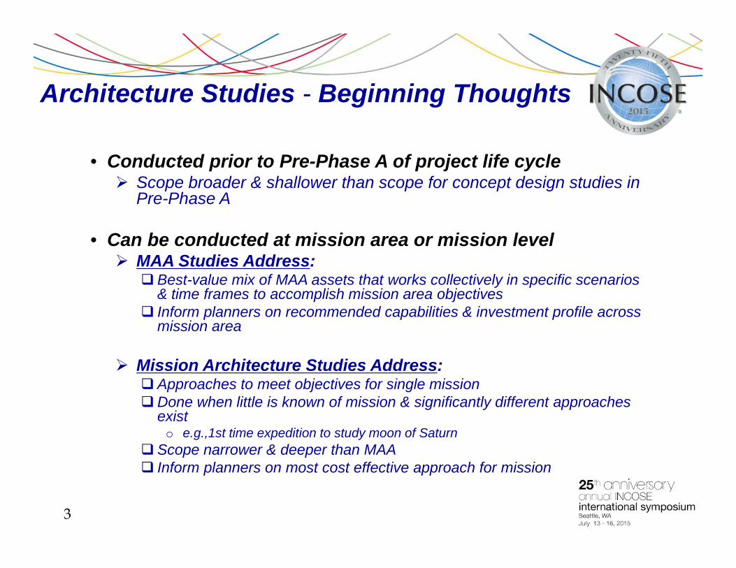
Architecture Studies - Beginning Thoughts
• Conducted prior to Pre-Phase A of project life cycle Scope broader & shallower than scope for concept design studies in
Pre-Phase A
• Can be conducted at mission area or mission level MAA Studies Address: Best-value mix of MAA assets that works collectively in specific scenarios
& time frames to accomplish mission area objectives Inform planners on recommended capabilities & investment profile across
mission area
Mission Architecture Studies Address: Approaches to meet objectives for single missionDone when little is known of mission & significantly different approaches
exist o e.g.,1st time expedition to study moon of Saturn
Scope narrower & deeper than MAA Inform planners on most cost effective approach for mission

July
4
Architecture Development Precedes Concept Design in Project Life Cycle (Fig. 1)
Adapted from NASA Project Life Cycle NASA Procedural Requirements (NPR) 7120.5E
Pre-Phase A
Concept Studies
Phase A
Concept & Technology
Development
Phase B
Preliminary Design &
Technology Completion
Phase C
Final Design &
Fabrication
Phase D
System Assembly, Integration &
Test, Launch & Checkout
Phase E
Operations & Sustainment
Phase F
CloseoutArchitecture Development
Project Life Cycle

July
5
Architecture Frameworks
• Many architecture frameworks reported developed or in use A survey of over 60 frameworks is at iso-architecture.org (see ref. (a)),
including those for:
Enterprise, defense, information, software, automotive, business, security, etc.
Varying scope & taxonomies

July
6
Objective 1
• Describe what an MAA is and show how it integrates into the NCS architecture framework

July
7
Beginning Definitions
• Before getting started, just what is an “architecture”?
Design? Building codes? Behaviors?

July
8
Beginning Definitions (Cont’d)
• New Webster Dictionary (1975) defines “Architecture” as:1) the art or science of building; specif. the art or practice of designing
and building structures and esp. habitable ones 2) formation or construction as, or as if, the result of conscious act3) architectural product or work4) a method or style of building
• New Webster Dictionary (1975) defines “Architect” (from Latin “architectus”, from Greek: “architekton” or master builder) as: 1) one who designs buildings & superintends their construction 2) one who plans and achieves a difficult objective (e.g., a military
victory)

July
9
What is the “NCS Architecture”?
• From these definitions, it’s clear architecting involves some level of design, but What level of design, and is design all there is to it? What does an architecture look like, and what does it do?
• To answer these questions for the NCS Architecture, we’ll need a common view of: Core elements & constituent MAAs of NCS architecture

July
10
Core Elements of an NCS Architecture
1) The set of functional capabilities that characterizes actual or forecast capabilities of NCS physical assets & human command & control (C2) entities Includes “what” capability will be delivered along with measures of
performance (MOPs), e.g., Quality, quantity, timeliness, interoperability, & robustness (QQTIR)
(Note: this is a minimum set of metrics)
2) The set of NCS physical assets (hardware/software) that is, (or is forecast to be) available along with their interconnectivities Shows “how” architecture functional capabilities will be delivered
3) The set of NCS human C2 operator / decision maker entities available along with their interconnectivities Note: Automated C2 assets are considered part of physical assets

July
11
Core Elements of an NCS Architecture (Cont’d)
4) The concept of operations (CONOPS) that identifies how NCS physical assets & human C2 entities will be employed in time sequence to meet a defined mission Used to evaluate effectiveness, etc., as function of environment & scenario
5) The set of constraints, i.e., rules / policies & standards / protocols, that constrain use of NCS assets & human C2 entities
• Each element above pertains to specific period in time, or “epoch”

July
12
NCS Architecture Framework Example
• Framework is established by functional decomposition Standard systems engineering (SE) technique
• Enables means to identify Vertical flowdown of guidance Horizontal interfaces within & among architectures

July
13
NCS Architecture Framework ExampleSpace Access Mission Area Highlighted (Fig. 2)

July
14
Functional Decomposition Example Space Access Mission Area (Epoch = 20xx)
• Tier 0: NCS architecture functions applicable to all mission areaso Tier 0 represents Enterprise Level
• Tier 1: Allocates Tier 0 functions to mission areas, e.g., provide Space Access
• Tier 2: Allocates Tier 1 functions to sub-mission area functions (e.g., provide Spacelift / Payload Transportation, etc.)
• Tier 3: Allocates Tier 2 functions to more detailed functions (e.g., deliver, deploy, retrieve, return, etc.)
• Tier 4: Allocates Tier 3 functions to metrics (QQTIR) & MOPs,e.g., for “deliver” function
o Example quantity metric = x payloads of y,000 kg to z,000 km circular orbit at i°inclination
o Example MOP = 2 payloads of 2,000 kg to 400 km circular (adds specific values) orbit at 51.6°inclination
• Tier 5: Allocates Tier 4 to physical assets & human C2 entities
Note: Number of tiers can vary among mission areas

July
15
Role of Higher Tier Guidance
• Tier 0: Provides guidance for all mission areas, e.g., Environmental policy (e.g., power / fuel sources, orbital debris, planetary
protection, etc.) Interoperability standards Criticality categories which drive level of robustness (or fault tolerance
needed); might pertain to assuring: 1) Human survival 2) Specific mission operational capabilities 3) Specific technology capabilities
• Tier 1: Adds guidance unique to each Tier 1 mission area
• Note: A fault means loss of capability for any reason (component failure, hostile
action, etc.) Severity of potential fault can depend on severity of threat

July
16
Functional Decomposition Table ExampleSpace Access Mission Area (Epoch = 20xx) (Table 1)

July
17
Physical View for Space Access MAA Assets (Fig. 3)

July
18
NCS Architecture May be Influenced by Other Notional Architectures (Fig. 4)
NCS architecture may be part of larger notional collection of architectures that crosses domains & stakeholders
Integration with adjacent architectures may impose additional constraints

July
19
• MAA technical analysis typically limited to 1st principles
• For space access MAA with tugs that maneuver spacecraft, architecture development team (ADT) might size tugs at rocket equation (ref. k) level Tug mass might scale to 1st order via rocket equation & other
relationships, e.g., dry mass to propellant mass ratio, etc.
• No detailed tug subsystem design conducted
Example Level of “Design” Work in MAA Development
July
20
Measures Of Effectiveness (MOEs)
• MOEs - typically address effectiveness at architecture level & differ from MOPs, e.g., MOP might pertain to sizing nodes for spacelift, range, & on-orbit
servicing functions MOE might pertain to how well these nodes combine to meet an
operational scenario at MAA level
• MOEs typically need to be decomposed into measurable terms in order to be useable by ADT Need early & continued customer / user engagement to develop & refine

July
21
Architecture Scenarios & Environments
• Scenarios Include driving operational cases at architecture level
• Environments typically are assumed conditions in which architecture will be developed & / or operated, e.g., Stable / cooperative vs. unstable / uncooperative governments Stable vs. unstable budgets Contested vs. uncontested space operations Orbital debris / space weather, etc.
• Key enabler for NCS architecture level effectiveness analysis Consistent scenarios & environments at MAA & NCS levels for given
epoch

July
22
Mission Area CONOPS Development & Use
• Each MAA has at least one CONOPS that applies to a particular scenario, environment, & epoch Used to evaluate MAA effectiveness
• CONOPS is specific to architecture design i.e., scenario is met differently by CONOPS using RLVs & on-orbit
servicing than by a CONOPS using only ELVs
RLV = Reusable launch vehicle ELV = Expendable launch vehicle

July
23
Some Uses for NCS Architecture Framework
• Provides for structured flowdown of policy & guidance into MAAs Establishes common lexicon for functions, metrics, & products Provides coherent context & relationships among architecture elements Enables horizontal & cross organizational integration within / among MAAs
• Allows synthesis of Tier 0 (enterprise) architecture from constituent MAAs for given epoch Facilitates identifying Tier 0 CONOPS & evaluating Tier 0 architecture
effectiveness
• Exposes gaps / overlaps indicating need for follow-on MAA studies
• Highlights whether studies are for: a) One mission area across all QQTIR metrics b) All mission areas for only one metric, e.g., timeliness

July
24
Objective 2
• Describe an effective approach for developing an MAA

July
25
Terms of Reference (TOR)
• TOR identifies Who, what, where, why, when of study process & products Incl. resources, participants, roles & responsibilities
• TOR typically will include Problem background (incl. relationship to relevant past studies) Problem statement: Concise & clear Study scope & product depth, i.e., Functional boundaries (e.g., include spacelift, exclude on-orbit servicing) Stakeholders Domains EpochMission area guidance (e.g., relevant policy directives, etc.)
Guidance for establishing MOEs Definitions for key unique terms

July
26
Assumptions, Constraints, Groundrules System (x) from stakeholder (y) is out of scopeUse data from source (z) as principal input Scenarios & environments Technology readiness date Policy, Cost
Guidance on how to select recommended architecture e.g., single, best value architecture within cost constraint, etc.
• TORs are deceptively difficult, but worth time to develop well Weak TOR can delay product deliveryCan leave ADT to define purpose, scope, depth, epoch, products while
designing MAA ADT view may not match customer view
Terms of Reference (TOR) (Cont’d)

July
27
Scope & Depth Considerations for TOR (Fig. 5)

July
28
“As-Is”, “To-Be”, “Should-Be”, & “Evolved Baseline” MAAs* (Fig. 6)
* Adapted from model used by ref. (l)

July
29
Conducting Effective Architecture Studies
• Lets now look at one way to effectively conduct an MAA study A generic, iterative “design cycle” process
• Important Note: MAA studies can be conducted more than one way

July
30
Introduction to Design Cycle Process for Architecture Studies
• Design cycle process is structured, iterative approach Based on standard SE technique for conducting requirements
development, design, & analysis Brings products to common, coherent reference point in each cycleMaintains synchronization of assumptions, trades & analyses Accelerates start of architecture design Provides discrete opportunities for stakeholder / management review Facilitates systems level integration Improves final report & reduces work required to produce it
• Other process models (e.g., waterfall, ad-hoc iterative, etc.), less effective for studies with high uncertainty Waterfall (i.e., linear, unidirectional) processes more effective for tasks
that are well understood Ad-hoc iterative processes difficult to keep synchronized

July
31
Introduction to Design Cycle Process for Architecture Studies (Cont’d)
• First time MAA developments are inherently exploratory & uncertain Teams learn at high rate Unknown-unknowns often emerge as byproduct of design workCan’t be planned for in advance
• Can’t plan all study details at outset Outline general plan (incl. major activities & milestones) early Develop schedule template for each design cycle Allows cycles to be moved & tailored, to minor extent, within general plan
• Starting design work early accelerates learning Surfaces unknown-unknowns early Allows adjustments when there is still time to resolve

July
32
Design Cycle Approach OverviewConducted in 3 Cycles
• Cycle 1: Pathfinder; learn & assess readiness for design a) “requirements” characterized in form usable for analysis b) metrics compatible with modeling tools c) modeling tools can analyze design to provide desired product set d) desired product set suffices to answer problem statement in TOR
Analyze a few architectures that span solution space Surrogates can be used for “requirements”, technology forecast
• Cycles 2a & 2b: Conduct comprehensive investigations for broad range of candidate
architectures Determine most promising architectures across trade space
• Cycle 3: Refine designs & analyses on most promising representative
architectures of solution space Recommend single architecture based on criteria in TOR

July
33
12-Month MAA Study Design Cycle TemplateCY 2005/2006 Example with Pre-Design Products Available(Fig. 7)
July
34
Pre-Design ProductsDraft Products Developed before Cycle 1
• Pre-Design Products Accelerate Cycle 1 start Functional decomposition through performance metrics Generic scalable physical nodes
Prepare for modeling use, incl. governing equations / relationships Generic “threads” (see next chart) Types of modeling tools available to analyze nodes
Technology forecast (to degree readily available in roadmaps, etc.) MOEs previously used or identified for mission area Summary of known mission area guidance & relevant studies
• Pre-design products may also include Data collection templates that support development of technology
forecast and “as-is”, “to-be” (planned), & EBL architectures

July
35
• Analyses of individual nodes combine to determine performance / effectiveness of “threads” Threads contain all nodes needed to deliver an end-to-end service, e.g., Deliver payload to orbit includes nodes for: launch base, ground station,
range, launch vehicle, human C2 entities
• Analyses of individual “threads” combine to determine performance / effectiveness of MAA ADTs assign combinations of threads to a range of candidate MAAs
• Functional decomposition for final MAA solution transferred into NCS functional decomposition table Formats similar
Architecture Trade Case MatrixSpace Access Example

July
36
Architecture Trade Case MatrixLeverages Functional Decomposition Table Format(Table 2)
Space Access Example, Epoch = 20xx Architecture Solution (How’s) => Functions / MOPs (What’s)
1a 1b 1c 2a 2b 2c 3a 3b 3c 4a 4b 4c 5a 5b 5c 6a 6b 6c
Provide Space Access Capabilities All ELV
Mix ELV /
RLV
All RLV w/Tugs
Provide Spacelift / Payload Transportation Capabilities - Deliver - Quality
Each “architecture” is a composite of several “threads” designed to meet MOPs Architecture #1 represents an all ELV solution where threads 1a, 1b, & 1c might include light, medium, & heavy ELVs, respectively. Architecture #3 represents an all RLV solution with tugs, where threads 3a, 3b, & 3c might include light RLVs, medium RLVs, & medium tugs, respectively.
- Quantity
- Timeliness
- Interoperability
- Robustness
- Deploy (QQTIR as above) - Retrieve (QQTIR as above) - Return (QQTIR as above) Provide Range / Launch Base Capabilties
Expand as done for Spacelift / Payload Transportation
Provide On-Orbit Servicing / Utilities Capabilities
Expand as done for Spacelift / Payload Transportation

July
37
Typical Design Cycle Products (Table 3)(1 of 2)
Product Cycles User Needs / “Requirements” Classes & Bounding Cases *, 2a, 2b, 3 Scenarios 1, 2a, 2b, 3 Future Environments / Threat Assessment 1, 2a, 2b, 3 CONOPS 1, 2a, 2b, 3 Doctrine / Policy Assessment 1, 2a, 2b, 3 Functional Decomposition (incl. MOPs / Interface “Req’ts") 1, 2a, 2b, 3 Tradespace & Trade Case Matrix 1, 2a, 2b, 3 Architecture Alternative Point Designs 1, 2a, 2b, 3 “As-Is”, “To-Be” (Planned), & EBL Architectures 2b, 3 Technology Forecast *, 2a, 2b, 3 Note: Shading aggregates products into ADT subteam reports
1) Operations: Green shading2) Systems: Blue shading3) Analysis: Yellow shading4) Architecture SE: Grey shading
* Surrogates may be used for Cycle 1

July
38
Typical Design Cycle Products (Table 3)(2 of 2)
Product Cycles MOEs 1, 2a, 2b, 3 Performance / Utility Analyses 1, 2a, 2b, 3 Vulnerability Assessment 1, 2a, 2b, 3 Work Breakdown Structure 1, 2a, 2b, 3 Cost Analysis 1, 2a, 2b, 3 Risk Assessment 1, 2a, 2b, 3 Subteam Technical Reports 1, 2a, 2b, 3 Systems Engineer Report 1, 2a, 2b, 3

July
39
Some Additional Recommended Practices for MAA Development
• Set “Should-Be” epoch far enough out for candid discussion 25 years: Allows candid discussion of future architecture 15 years: Discussion highly constrained by current budget
• Keep Cycle 1 short, but apply concerted effort Avoid pressure to use results from Cycle 1 for budget inputs
• Don’t retrofit architectures from prior cycles Just apply what’s been learned to future cycles
• Exercise full solution space in Cycles 1, 2a & 2b• Start writing ADT report in Cycle 1, refine in Cycles 2 & 3 Write reports first (documents of record), then translate to briefings
• Remain impartial

July
40
• Approach presented uses simple extension of SE that can help ADTs, their customers, & stakeholders: Quickly understand core elements of an enterprise architecture when
planning for far-term future Visualize how constituent MAAs might get developed & integrated into an
enterprise architecture
• As approach is based on widely understood SE techniques & terminology, it should: Be readily usable by wide range of teams without need for special
training in more complex & abstract methods Have application beyond space architecture development
Closing Thoughts

July
41
Questions ?

July
42
• a) iso-architecture.org. 2014. “Survey of Architecture Frameworks.” Last accessed 3 September 2014. http://www.iso-architecture.org/ieee-1471/afs/frameworks-table.html.
• b) Di Pietro, David A. 2009. “National Security Space (NSS) Architecture Development Process (Draft).” Briefing to Mr. J. Rouge, Director National Security Space Office, Washington, DC (US). Presented and approved 9 February.
• c) Di Pietro, David A. 2009. “Space Mission Architecture Development, Notional Framework and Approach.” Training course presented at the NASA Goddard Space Flight Center, Greenbelt, MD (US). 30 September.
• d) Di Pietro, David A. 2014. “A Systems Engineering Approach to Architecture Development.” Briefing presented (http://www.dtic.mil/ndia/2014system/2014system.html) at the National Defense Industry Association 17th Annual Systems Engineering Conference, Springfield, VA (US). October 2014.
• e) NASA Headquarters. 2012. NASA Procedural Requirements (NPR) 7120.5E w/Changes 1-10. NASA Space Flight Program and Project Management Requirements, Figure 2-5. Washington, DC (US): Office of the Chief Engineer.
References

July
43
• f) Razzaghi, Andrea I., Di Pietro, David A., Simon-Miller, Amy A., and Spencer, John R. 2007. Enceladus Flagship Mission Concept Study, Revision 1, Edited for Public Release. NASA Goddard Space Flight Center, Greenbelt, MD (US). 2 November.
• g) Razzaghi, Andrea I., Di Pietro, David A., Quinn, David A., Simon-Miller, Amy A., and Tompkins, Stephen D. 2008. “Mission Concepts for Studying Enceladus.” Paper presented at Space Technology & Applications International Forum, Albuquerque, NM (US). 14 February.
• h) G. & C. Merriam Co. 1975. Webster’s New Collegiate Dictionary. Springfield, MA (US).
• i) Wikipedia. 2014. “Propellant_depot.” Last accessed 5 October 2014. http://en.wikipedia.org/wiki/Propellant_depot.
• j) Wikipedia. 2014. “Space_tug.” Last accessed 5 October 2014. http://en.wikipedia.org/wiki/Space_tug.
• k) Brown, Charles D. 1998. Spacecraft Mission Design. 2nd Edition. Equation 3.21. Reston, VA (US): American Institute of Aeronautics and Astronautics.
References (Cont’d)

July
44
• l) Hagemeier, Hal E. 2009. Deputy Director, National Security Space Office. Washington, DC (US).
• m) Rader, Andrew A., Ross, Adam M., and Fitzgerald, Matthew E. 2014. "Multi-Epoch Analysis of a Satellite Constellation to Identify Value Robust Deployment across Uncertain Futures." Paper presented (http://seari.mit.edu/publications.php#2015) at AIAA Space 2014, San Diego, CA, August 2014.
References (Cont’d)

July
45
Backup Charts

July
46
Interface Identification
• Horizontal interfaces (within or among MAAs) can be highlighted on functional decomposition e.g., transmit data rate / frequency from remote sensing node
(Environmental Monitoring MAA) to ground station (SATCOM MAA)
• Some physical interfaces may need to be standardized e.g., for some on-orbit servicing nodes
• Horizontal integration analyses across MAAs validate interfaces are compatible

July
47
Example “Requirements” Trade SpaceSpace Access Example