a sustainable nuclear fuel cycle based on laser inertial fusion
TRANSCRIPT

A SUSTAINABLE NUCLEAR FUEL CYCLE BASED ON LASER INERTIAL FUSION ENERGY
Edward I. Moses, Tomas Diaz de la Rubia, Erik Storm, Jeffery F. Latkowski, Joseph C. Farmer, Ryan P. Abbott,
Kevin J. Kramer, Per F. Peterson,* Henry F. Shaw and Ronald F. Lehman II
Lawrence Livermore National Laboratory, 7000 East Ave., Livermore, CA 94550 *University of California, Berkeley, CA, 94720 Email: [email protected], Fax: (925) 423-5957
The National Ignition Facility (NIF), a laser-based
Inertial Confinement Fusion (ICF) experiment designed to achieve thermonuclear fusion ignition and burn in the laboratory, will soon be completed at the Lawrence Livermore National Laboratory. Experiments designed to accomplish the NIF’s goal will commence in 2010, using laser energies of 1 to 1.3 MJ. Fusion yields of the order of 10 to 35 MJ are expected soon thereafter. We propose that a laser system capable of generating fusion yields of 35 to 75 MJ at 10 to 15 Hz (i.e., ≈ 350- to 1000-MW fusion and ≈1.3 to 3.6 x 10 20 n/s), coupled to a compact subcritical fission blanket, could be used to generate several GW of thermal power (GWth) while avoiding carbon dioxide emissions, mitigating nuclear proliferation concerns and minimizing the concerns associated with nuclear safety and long-term nuclear waste disposition. This Laser Inertial Fusion Energy (LIFE) based system is a logical extension of the NIF laser and the yields expected from the early ignition experiments on NIF. The LIFE concept is a once-through, self-contained closed fuel cycle and would have the following characteristics: (1) eliminate the need for uranium enrichment; (2) utilize over 90% of the energy content of the nuclear fuel; (3) eliminate the need for spent fuel chemical separation facilities; (4) maintain the fission blanket subcritical at all times (keff <0.90); and (5) minimize future requirements for deep underground geological waste repositories and minimize actinide content in the end-of-life nuclear waste below the Department of Energy’s (DOE’s) attractiveness Level E (the lowest). Options to burn natural or depleted U, Th, U/Th mixtures, Spent Nuclear Fuel (SNF) without chemical separations of weapons-attractive actinide streams, and excess weapons Pu or highly enriched U (HEU) are possible and under consideration. Because the fission blanket is always subcritical and decay heat removal is possible via passive mechanisms, the technology is inherently safe. Many technical challenges must be met, but a LIFE solution could provide a sustainable path for worldwide growth of nuclear power for electricity production and hydrogen generation.
I. INTRODUCTION Projections by the Energy Information Agency and
current Intergovernmental Panel on Climate Change (IPCC) scenarios show that worldwide electric power demand is expected to double from its current level of about 2 to 4 TWe by 2030 and could reach 8 to 10 TWe by 2100.1,2 It is also expected that for the next 30 to 50 years, the bulk of the electricity production will continue to be provided by fossil fuels such as coal and natural gas. Today, coal supplies 41% of the world’s electric energy and is expected to supply 45% by 2030.1 In addition, the most recent report from the IPCC has placed the likelihood that man-made sources of CO2 emissions into the atmosphere are having a significant effect on the climate of planet earth at 90%.2 And “business as usual” baseline scenarios show that CO2 emissions could be almost two and a half times the current level by 2050. Clearly, new technologies and alternative sources of energy will be required as early as possible in the 21st century to meet the increasing energy demand in both the developed and the developing worlds, while attempting to stabilize the concentration of CO2 in the atmosphere and mitigate the concomitant climate change.
Nuclear energy, a non-carbon emitting energy source, has been a key component of the United States’ and world’s energy production since the 1960s and currently accounts for about 16% of the world’s electricity production, a fraction that could – in principle – be increased.3 However, several factors make its long-term sustainability difficult. These concerns are associated with the risk of proliferation of nuclear materials and technologies resulting from the nuclear fuel cycle; the generation of highly radioactive, long-lived nuclear waste that requires burial in deep geological repositories; and with the current reliance on the once-through, open nuclear fuel cycle, the availability of low-cost uranium ore resource for the long term. Just in the United States alone, the past and current fleet of nuclear reactors has generated more than 55,000 metric tons (MT) of

commercial Spent Nuclear Fuel (SNF), and we will soon have enough SNF to fill the Yucca Mountain geological waste repository to its legislated limit of 70,000 MT.
Fusion is an attractive energy option for the future, and two main approaches to fusion power plants are being developed worldwide. Inertial Confinement Fusion (ICF) would use lasers, heavy ion beams, or pulsed power to rapidly compress a capsule containing a mixture of deuterium and tritium (DT) gas. As the capsule radius decreases and the DT gas density and temperature increase, DT fusion reactions are initiated in a small spot in the center of the compressed capsule. These DT fusion reactions generate both alpha particles and 14.1-MeV neutrons, and a fusion burn front propagates, generating significant energy gain.4 Magnetic fusion energy, or MFE, uses powerful magnetic fields to confine a low-density DT plasma and to generate the conditions required to sustain the burning plasma for a sufficiently long time to generate energy gain.
The capability of lasers to create the conditions required for ignition and propagating thermonuclear burn in the laboratory with ICF is expected to be demonstrated on the National Ignition Facility (NIF) a full decade ahead of MFE experiments planned for the International Thermonuclear Experimental Reactor (ITER) facility under construction in Cadarache, France.5,6 The National Ignition Campaign (NIC) will begin during 2009, and ignition and modest target gain ~10 (G = fusion yield/laser energy), for laser energies of 1-1.3 MJ, resulting in fusion energy yields of 10 – 15 MJ is anticipated during FY 2010/2011. Ultimately, fusion yields of 100 MJ could be possible on NIF. Successful demonstration of ignition and net energy gain will be a transforming event for inertial fusion and is likely to focus the world’s attention on the possibility of ICF as a potential energy option.
The first experiments to demonstrate ignition and gain will use 350-nm laser light with a central hot spot ignition (HSI) target in an indirect drive configuration for which the scientific basis has been intensively developed.7,8 The NIF ignition and burn experiments with HSI targets are expected to be successful. The target gains of the order of 100 that would be required for efficient, cost effective inertial fusion power generation with HSI targets should ultimately be possible. However, the larger laser energies (~2.5 MJ) and corresponding fusion yields (150-200 MJ) needed for pure inertial fusion energy (IFE) systems would require additional development.
To mitigate the challenges of nuclear energy and advance the time scale of the usefulness of fusion sources, we are developing a novel once-through, self-contained closed nuclear fuel cycle: a fusion driven fission engine that combines the best aspects of nuclear fusion and fission. Our approach, which we term Laser Inertial Fusion Energy, or simply LIFE, consists of an ICF neutron source (typically 1-2 x 10²⁰ n/sec) surrounded by
a spherical subcritical fission fuel blanket. In LIFE, the point source of fusion neutrons acts as a catalyst to drive the fission blanket, which obviates the need for a critical assembly to sustain the fission chain reaction. In this manuscript, we show how starting from a 15–20 MW laser providing as little as 300 to 500 MW of fusion power, a single LIFE engine can generate 2000 to 5000 megawatts of thermal power (MWth) in steady state for periods of years to decades, depending on the nuclear fuel and engine configuration. (a follow-on paper will describe how advanced fusion target options could provide the same thermal output power with a 6–8 MW laser.) The source of ‘external neutrons’ drives the subcritical fission blanket and makes the various LIFE engines described in this paper capable of burning any fertile or fissile nuclear material, including un-enriched natural or depleted uranium (DU) and SNF. A LIFE engine can extract virtually 100% of the energy content of its nuclear fuel resulting in greatly enhanced energy generation per unit of nuclear fuel. The external source of neutrons also allows the LIFE engine to burn the initial fertile or fissile fuel to more than 99% FIMA (Fission of Initial Metal Atoms) without refueling or reprocessing, allowing for nuclear waste forms with significantly reduced concentrations of long-lived actinides per GWe-yr of electric energy produced. The energy and materials flow for LIFE engine is shown schematically in Figure 1.
Fig. 1. The energy and materials flow for the NIF/NIC-based Laser Inertial Fusion Energy (LIFE) engine. LIFE provides an option for a once-through, closed nuclear fuel cycle that starts with a 15-20 MW laser system to produce 375-500 MW of fusion power and uses a subcritical fission blanket to multiply this to 2000–5000 MWth.
LIFE engines, thus, could provide the ability to
generate base-load electricity while greatly reducing the actinide content of any existing or future nuclear waste

and extending the availability of low-cost nuclear fuels for thousands of years. LIFE also provides an attractive pathway for burning excess weapons Pu to over 99% FIMA without the need for fabricating or reprocessing mixed oxide fuels (MOX). Because of all of these advantages, LIFE engines offer a pathway toward sustainable and safe nuclear power that significantly mitigates nuclear proliferation concerns and minimizes nuclear waste.
Andrei Sakharov discussed the idea of fusion driven fission systems in the 1950s.9 Hans Bethe and Nikolai Basov expanded on his ideas in the 1970s and 1980s, as did many other groups around the world.10-13 The focus of many of these studies was on the use of fusion neutrons to generate fuel for fast nuclear reactors, although Basov and his colleagues as well as Maniscalco and his co-workers at LLNL also discussed the possibility of using laser-driven fusion targets to drive a fission blanket for generating commercial power. Many proposals have also been made to use accelerators to generate neutrons that can then be used to transmute nuclear waste and generate electricity.14,15 Unfortunately, fusion driven fission systems never advanced beyond the discussion stage mainly because, at the time, the demonstration of fusion ignition was judged to be several decades away, and powerful high-average-power lasers and other required technologies did not exist. Similarly, accelerator-based schemes never advanced past the conceptual study phase, in part because a complete nuclear fuel cycle - including U enrichment and nuclear waste reprocessing - was still required to generate economical electricity, and as a result, the efficiency and cost of those systems proved to be prohibitive relative to the benefit of transmuting nuclear waste. Today, however, advances at the NIF and other ICF facilities around the world are putting scientists and engineers close to demonstrating the physics and key technologies required to make LIFE a reality. In fact, we believe that with the appropriate research, development and engineering program, LIFE engines could start providing electricity to U.S. consumers relatively soon and could provide a very significant fraction of U.S. and international electricity demand by 2100 (see section on LIFE scenarios below). LIFE could also be configured to use its process heat to power material and other manufacturing processes, and with advanced materials, directly produce hydrogen for transportation.
II. SYSTEM DESCRIPTION AND PERFORMANCE
LIFE is a logical extension of the NIF laser, the
National Ignition Campaign on NIF described above and
ongoing developments in the world nuclear power industry. The LIFE power plant system (see Figure 2) discussed in this paper comprise a 10- to 15-Hz, diode-pumped solid-state laser (DPSSL) with an efficiency of 10-15% (laser power delivered to the fusion target/electric power input to the laser), a fusion target factory, a fusion target chamber surrounded by a subcritical fission blanket, and the balance of the plant.16-20
The baseline NIF-based LIFE system is designed to operate with fusion energy gains of 25–30 and fusion yields of 30 to 40 MJ to provide 350–500 MW of fusion power, approximately 80% of which comes in the form of 14.1-MeV neutrons, with the rest of the energy in X rays and ions. This approach to fusion generates approximately 1019 14.1-MeV neutrons per shot, or approximately 1020 n s-1. The LIFE fusion system is thus a logical extension of the single-shot NIF laser and NIF yields. As will be discussed further in the section below describing the LIFE fission system, when used to drive the sub-critical fission blanket, these fusion neutrons generate an additional energy gain of 4–10 depending upon the details of the fission blanket, to allow overall LIFE system energy gains of 100–300.
The additional fission gain has important consequences for the overall LIFE system, as compared with a pure IFE option. We note that for a relatively conservative value of the laser driver efficiency, η, of 10%, a fusion gain of 25 and a fission gain of 8, resulting in a total system energy gain, G, of 200, a LIFE engine would have an efficiency figure of merit ηG = 20. If (for the sake of this example) we ignore the ~20–30 MW needed for pumps and auxiliary power, the recirculating power fraction required to run the laser would then be f = 1/ηe /(ηG), where ηe is the thermal to electrical power conversion efficiency of the power plant. For ηe = 43%, such as has been proposed with a Brayton fuel cycle, f in this case would be only ~11%.21 In contrast, a pure fusion system with a fusion gain of only 25 would not be economically viable, since with an efficiency figure of merit ηG = 2.5, greater than 90% of the electric power generated would be required to run the laser.
The current “canonical” large coal and nuclear central power plants in the U.S. provide around 1,000 MWe. It is anticipated that in the future, there will be a demand for somewhat larger plants, perhaps around 1,500 MWe. In the following sections, LIFE fusion and fission systems designed to deliver electric power in the 1,000 to 1,500 MWe range are discussed.

Fig. 2. Conceptual design of a LIFE engine based on the inertial fusion yields of 35 MJ expected from indirectly driven hot-spot ignition targets on NIF from 1.4 MJ. The diode-pumped solid-state laser operates with at 13.3 Hz and a wavelength of 350 nm. The 2.5-m-radius chamber is shown, and the final optics are 25 meters from the target. II.A. LIFE Fusion Systems
The fusion systems required for a LIFE engine
include the fusion target, the target chamber, a laser driver, and a target factory/target injection system. Each of these components will be described in the following subsections.
II.A.1. LIFE inertial fusion target
HSI targets, and in particular HSI in the indirect-
drive configuration, will be used for the first ignition demonstration on NIF, and are the current baseline ICF target approach for LIFE. The Fast Ignition (FI) approach to ICF is a possible future target option for LIFE.22 It offers potential advantages, notably considerably higher fusion gain for a given laser energy. However, the physics basis of FI is not as mature as the HSI approach.
HSI relies on simultaneous compression and ignition of the spherical fuel capsule in an implosion. In the indirect-drive configuration, the spherical DT-filled capsule is placed inside a cylindrical cavity of a high-Z metal (a hohlraum), and the implosion pressure is provided by focusing the 350-nm NIF laser energy onto the interior walls of the hohlraum and converting it to X rays (see Figure 3). The small (<1% of the total DT fuel mass), high-temperature central part of the imploded fuel provides the “spark,” which ignites the cold, high-density portion of the fuel. For typical compressed configurations, DT burn-up fractions of about 25% are calculated. This approach has a high probability of success, but requires a highly symmetric implosion configuration to maintain spherical symmetry in the imploding fuel to avoid mixing of the cold main fuel into the hot spot. Such a mix would quench the ignition process and places limits on the mass of DT fuel (and hence the fusion yield) per MJ of compression laser energy that can be assembled to the

required conditions. Figure 3 also shows the calculated fusion yield as a function of laser energy and as a function of the wavelength of the laser for HSI targets.23
Fig. 3. Calculated fusion yield curves as a function of total laser energy for hot spot ignition (HSI) targets. The temperatures indicated (eV) are the hohlraum radiation temperatures that provide the compressive drive for the capsules. The wavelength of the compression laser changes along the yield curve as indicated. The width of the band indicates uncertainty in hohlraum performance.
II.A.2. LIFE target chamber
Figure 4 shows a cutout of a 2.5-m-radius LIFE
fusion chamber dimensioned to handle 500 MW of fusion power generated by a HSI target with a yield of 37.5 MJ and a repetition rate of 13.3 Hz.
To “manage” the 400 MW of 14.1-MeV neutrons, as well as the ~100 MW of high-energy X rays and ions generated by the target, the chamber structural steel wall will be made of low-activation, nano-structured oxide dispersion-strengthened (ODS) ferritic steel to provide resistance to damage by fusion neutron irradiation, over coated with 250–500 µm of tungsten to handle the high temperatures resulting from absorption of the x-rays emitted from the LIFE targets.20,24 The target chamber and beam path will be filled with a mixture of argon, krypton and xenon gas at an atomic density of ~1 × 1016 cm-3. These gases will absorb the majority of the x-ray energy and stop essentially all ions emitted from the indirect-drive target. The hot gas will then cool via radiation on a timescale sufficiently long (a few hundred µsec) to prevent damage to the tungsten first wall. For a 37.5-MJ/500-MW HSI (or FI) target and a 2.5-m-radius chamber, the tungsten layer will experience a 1000-K temperature spike (Figure 5), well below the melting point of tungsten. The gas will be pumped out between shots through the laser beam entrance ports.20 To maintain similar chamber wall conditions for LIFE engines with
different fusion yields, the chamber radius would scale approximately with the square root of the fusion yield. This is shown graphically in Figure 6, which shows the fusion chamber scaling with fusion yield. To minimize neutron losses, (as will be discussed further below in the fission system section), the fission blanket thickness should be approximately constant (~1 m) to be neutronically thick.
Fig. 4. LIFE fusion-fission chamber for 37.5-MJ HSI target driven by a 1.4-MJ, 350-nm laser.
Fig. 5. The surface temperature rise in a 250-µm tungsten layer protecting the ODS steel first wall for a 37.5-MJ target yield in a 2.5-m-radius target chamber. The chamber is filled with ~ 1/3 torr of a mixture of Ar, Xe and Kr to absorb ~ 90% of the ~4.5 MJ of high energy x- rays and all of the ~4 MJ of ions produced by the target.
Consequently, for a constant operating repetition rate,
the mass of fission fuel loaded and the overall thermal power of a given fission fuel configuration (i.e., constant fission gain) tend to increase proportionally with the fusion yield. Figure 6 shows the net GWe generated for

various fusion yields and chambers for HSI targets for a fission energy gain of 6, a DPSSL efficiency of 10% and a thermal-to-electric conversion efficiency of 43%. These system trade-offs will be explored further below.
Fig. 6. LIFE chambers and net electric power as a function of HSI fusion yield for NIF-type illumination geometry for a fission blanket energy gain of 6, a laser efficiency of 10%, and a thermal-to-electric conversion efficiency of 43%.
The LIFE engine’s structural challenges include:
need for high-temperature strength; resistance to high-temperature creep; immunity to radiation damage, including swelling and helium embrittlement; resistance to corrosion and environmental cracking in high-temperature molten fluoride salts; and the ability to be fabricated into necessary shapes and configurations with practical welding processes. We anticipate that these challenges can be met with ODS ferritic steels, sheets and coatings of refractory metals such as tungsten, advanced solid or liquid fuels, and other advanced reactor materials. Given our current understanding of ODS ferritic steels, a neutron damage limit of 150–300 displacements per atom (dpa) appears possible.24 As shown in Figure 7, the dpa rate experience in the LIFE first wall would be ~35 dpa/year, and thus, a first wall lifetime of 4–8 years is anticipated. Although advanced first wall materials, with dramatically enhanced radiation hardness, may be developed, the LIFE engine has been designed with chamber replacement in mind. II.A.3. LIFE laser systems
The LIFE laser leverages experience in high-
energy/high-power Nd:glass laser technology developed for NIF, along with high-energy-class diode-pumped solid-state laser technology developed for the DOE’s High Average Power Laser Program, and embodied in LLNL’s Mercury laser system.19
Fig. 7. The neutron displacement rates vary from ~ 35 dpa/year in the first wall to 2.5-4 dpa/year in the fuel.
In many ways, NIF is a prototype for the LIFE laser.
As with NIF, the LIFE laser consists of a large number of individual (independent) beam lines or beamlets, each employing NIF’s basic multi-pass architecture with a few minor modifications to optimize performance for the specific fusion point design.18 High-average-power operation is enabled by replacing NIF’s passive cooling system with high-speed helium gas to remove heat from active laser components, as demonstrated in LLNL’s Mercury laser. To achieve required laser efficiency (10 to 15%), the flashlamps are replaced with a laser-diode pumping system (also demonstrated in Mercury). An increase in repetition rate by nearly five orders of magnitude results in average output power of order 100 kW per LIFE beamlet. Many of the other technologies required for high-average-power DPSSL, such as the thermal management of the optics, use of adaptive optics to correct thermal wavefront distortions, and methods for harmonically converting high-average-power laser beams and frequency conversion, have already been demonstrated with the Mercury system. LLNL has also demonstrated kJ-class petawatt laser systems including large-scale, high-damage-threshold diffractive optics that would be used for a fast ignition version of LIFE (this will be detailed in a follow-on paper on advanced LIFE options). Emerging technologies, such as transparent ceramics laser materials, could further improve LIFE’s performance and economics.
The LIFE final optic must deliver the laser to target with demanding specifications in a hostile environment. Past work, including high-dose neutron irradiations, has found that a transmissive silica Fresnel is likely to be a viable option.25 Additional work is needed to develop

sufficiently high efficiency Fresnels and to study the laser damage threshold of neutron irradiated material. However, considerable margin has been included in the current design with a final optic fluence of only 2 J/cm2.
II.A.4. LIFE fusion target systems
The LIFE target system must be capable of delivering
approximately one million ICF targets per day, each costing less than about 30-40¢, to the center of the LIFE target chamber. A combination of high-speed (200–400 m/sec), high-precision injection and tracking must be capable of determining where the target is and delivering the focused laser energy to an accuracy of a few tens of µm, or a few µradians with the anticipated stand-off distance for the final optics. The target system must also include recovery and recycling of the imploded target material residue.
Concepts for the production and delivery and recycling of low cost (~ 30¢/ea) ICF targets at 10–20 Hz have been proposed, and investigations at LLNL, General Atomics and elsewhere, although at an early stage, are encouraging. We anticipate that the LIFE targets will be made with technologies from high-volume manufacturing industries using techniques associated with consumer-oriented low-cost, high-accuracy, high-throughput factories.26 Heating and deflection during target injection and transport through the chamber environment have been examined and appear consistent with gas pressures of ~1/3 Torr.
The integrated process of target injection, in-flight tracking and beam engagement is a key technical requirement for LIFE. However, recent work at General Atomics have demonstrated many of the requirements in scaled experiments.27 The tracking and engagement accuracy requirements of a few µradians is also similar to those required for ballistic missile defense, and LIFE will leverage technologies developed for and by those programs. Significant progress has been made in recent years with the construction of a prototypical gas-gun injector and tracking systems.27 Experiments using room temperature surrogate targets (e.g., plastic slugs) achieved injection velocities of ~400 m/s at 6 Hz (batch mode operation) with repeatable accuracy of delivery to chamber center in the range of what is deemed acceptable to allow beam pointing necessary for proper target illumination (~100 µm for indirect drive). Additional development is needed for cryogenic targets and to achieve operation at the repetition rates of up to 15 Hz, but we see no fundamental physics limitations to achieving those objectives. II.B. LIFE Fission Systems
Although it is driven by nuclear fusion, described
above, LIFE generates the majority of its power from
nuclear fission. Crucial to this portion of the system are the fission fuel form, the thermal power removal and conversion systems, and the final waste disposition. These are described below.
II.B.1. LIFE fission fuel forms
After passing through the first wall, the fusion
neutrons enter a beryllium layer (Figure 4).20 9Be(n,2n)8Be reactions are used to multiply the neutrons, and approximately 1.8 neutrons (on the average) are generated for every fusion neutron that enters the beryllium region. Additionally, the beryllium “softens” the neutron significantly, as is shown in Figure 8. The softened spectrum results in nearly an order of magnitude more neutron flux at thermal energies (En ≤ 10-7 MeV). Neutrons at these energies are more effective at producing tritium and plutonium as well as inducing fission.
Fig. 8. A 16-cm-thick region of molten salt-cooled beryllium pebbles generates a softer neutron spectrum. The fluctuations at low neutron energies are due to statistical noise in neutron transport calculations.
The moderated and multiplied neutrons then strike
the next layer, an 80- to 100-cm-thick, subcritical fission blanket that is designed to maintain a keff <0.9 at all times. The fission fuel can either be in a solid or liquid form. Most of the analysis so far has been done with a solid fuel in the form of approximately 2-cm-diameter pebbles containing 1-mm-diameter enhanced TRISO (TRI-structural-ISO-tropic) fuel pellets embedded in a graphite or similar inert matrix (Figure 9), though several alternative high burn-up solid fuels are also being investigated.28,29

Fig. 9. An enhanced TRISO fuel, with a more robust SiC capsule to enable fission-gas containment, is being considered as one possible fuel option for LIFE.
The fuel pebbles are immersed in a liquid fluoride salt such as flibe (2LiF + BeF2) that carries away heat to drive electrical generators. In the current design, the fuel pebbles are expected to circulate through the fission blanket at a rate of 0.3 m/day (resulting in a ~30-day cycle time per pebble). The pebbles will be taken out for inspection at a rate of approximately two to three per second and reinserted randomly in the fission blanket to obtain homogeneous burn of the fuel. The very high volumetric heat capacity of liquid salts allows the fission blanket to be compact and have high-power density when coupled to a point source of fusion neutrons. The flibe input temperature is 610 °C, and the exit temperature for this design is 640 °C. ODS ferritic steel is thought to be compatible with flibe at these temperatures, although coating surfaces with the same tungsten coating used for the first wall is another option.
Our calculations show that for a LIFE design with 37.5-MJ fusion and a LIFE engine chamber of 2.5 m diameter, the temperature spike in the TRISO-based fuel pellets that results from the pulse of neutrons entering the fission blanket every 0.1 to 0.075 s is approximately 60 °C. An additional key design feature of the LIFE engine is the fact that the flibe coolant contains lithium, which produces tritium, which serves to replace the tritium burned in the fusion targets, thus making the LIFE engine self-sufficient in tritium.
TRISO fuel is being used for the baseline design. Based upon a thorough review of the technical and scientific literature, it is believed that an enhanced version of the INL-based TRISO (Figures 9 and 10) may already be an option for a 5- to 7-year weapons-grade plutonium (WG Pu) or HEU pebble capable of more than 99% burn-up in a LIFE reactor.29
New fuel designs will enable us to overcome the limitations of the current high burn-up fuels for natural or DU TRISO pebbles, limitations that arise primarily because of the inability of the graphite to tolerate the very
high neutron fluence, 150–300 dpa depending on the LIFE design. It is believed that a new Solid Hollow Core (SHC) design will help overcome these limitations. Higher-mass fraction of fertile material can be achieved with the new SHC fuel shown in Figure 11. The stress in the wall of SHC fuel at fission gas pressures resulting from burn-up as high as 99.9% FIMA has been predicted, and calculated values do not exceed the intrinsic strength of the irradiated materials.
Fig. 10. The experience base for TRISO fuels is limited, with 8 to 20% FIMA demonstrated with low enriched uranium (LEU) and 85% FIMA demonstrated with HEU. These LEU and HEU fuels experienced lower neutron fluences but at much high temperatures of 1100-1200°C.
Fig. 11. A wide variety of alternative materials and fuel designs are possible and are being evaluated. Higher-mass fraction of fertile material can be achieved with new SHC fuel. The specific use of sacrificial SiC in fuels is attributed to R. J. Lauf et al. [R. J. Lauf, T. B. Lindemer, R. L. Pearson, “Out-of-Reactor Studies of Fission Product / Silicon Carbide Interactions in HTGR Fuel Particles,” J. Nucl. Matls. 120 (1984) 6-30].
In addition to SHC, an Encapsulated Powder Fuel (EPF) form is envisioned. EPF fuels would utilize ODS ferritic steels or other cladding materials to enclose a

granular fuel/moderator mixture. Such fuels would incorporate sacrificial materials to chemically mitigate the more reactive fission products, thereby protecting the cladding materials. EPF fuels could be vented to remove the pressurized fission product gases, thus reducing the pressures that the pebble cladding must withstand.
The ability to also burn SNF from light water reactors (LWRs) would be an attractive feature for LIFE engines. The OREX process has been used to convert SNF into fuel for CANDU reactors, and could be used to manufacture SHC and EPF pellets.30
Unlike solid fuels, molten salts with dissolved uranium, thorium and plutonium will not be damaged by long-term exposure to neutron bombardment. From a purely technical point of view, such liquid fuels could, therefore, serve as ideal fuels for achieving nearly complete burn-up. Such molten salt fuels have been considered for graphite-moderated molten-salt breeder reactors that operate on the thorium-uranium fuel cycle and enable continuous on-line processing of the fuel. On-line processing is used to keep fission products at desirable levels, and in particular, to remove rare earth elements to avoid precipitation. The use of LiF with UF4 and ThF4 is currently being explored for LIFE.31 In-depth understanding must be developed through application of internationally accepted predictive codes such as THERMOCALC to predict the formation of various phases, including precipitates such as plutonium trifluoride (PuF3). The prediction of phase diagrams for complex liquid fuels, with large numbers of fission products, requires that the phase diagrams for several binary pairs of salts first be developed. For example, equilibrium phase diagrams have been predicted for relevant mixtures such as BeF2-LiF (flibe), BeF2-ThF4, BeF2-UF4, LiF-PuF3, LiF-ThF4, ThF4-UF4 and several other systems. Such systems would be operated at compositions and temperatures where no solid-phase precipitates form.
II.B.2. LIFE power generation and system configurations
For a 500-MW fusion-driven LIFE engine, the fission
blanket can be fueled with approximately 40 or 50 MT of fertile fission fuel (whether in a solid TRISO or SHC form or liquid form) such as depleted or natural U, SNF, or natural Th, or with 5–7 tons of fissile fuels such as excess weapons Pu or HEU. In all cases, the majority of neutrons that enter the subcritical fission blanket are absorbed either by lithium in the coolant, which in turn generates tritium that can be harvested to manufacture new DT fusion targets, or by the fission fuel where they drive neutron capture and fission reactions, releasing significant amounts of heat. Some neutrons are lost due to leakage or parasitic absorption in structural materials or fission products. In this manner, the gain of 25 to 30 for the baseline LIFE design (NIF-level HSI target
performance) obtained in the fusion process is multiplied in the fission blanket by another factor of 4 to 10, and approximately 2000 to 5000 MWth of power are generated by the system.32 The TRISO or SHC solid fuel systems with fertile fuel (natural or depleted U - and SNF if a solid option pebble can be developed for SNF) have fission gains of 4-6, while the solid form fissile systems (HEU and WG-PU) and liquid fuel systems all have fission gains of 6-8 and potentially as high as 10.
Because of the continuous availability of the (1-2 x 10²⁰) neutrons/sec from the fusion source, LIFE fuel could be burned to as high as 99% FIMA without reprocessing. A critical reactor would shutdown due to depletion of the fissile material. Of course, reaching such ultra-deep burn of the nuclear fuels requires significant advances in fuel materials for the solid fuel options and continuous on-line processing for the liquid fuel option.29,31
Figure 12 shows a typical power curve calculated for a LIFE engine loaded with 40 tons of DU.20,32 Following the initial steep rise, the power output of the LIFE engine is kept constant at approximately 2000 MWth by changing the 6Li/7Li ratio in the fluoride molten salt coolant. This alters the balance of neutrons that are utilized to generate tritium relative to those available to produce and/or fission fissile material in the fission blanket. As time progresses, 238U converts through neutron capture to 239Pu and higher actinides. Note that for the first ~20 years of the operation, there is an excess production of tritium. Since its half-life is 12.3 years, a significant fraction of the excess tritium will have been lost through decay by the last decade of operation.
0
1000
2000
3000
4000
0 10 20 30 40 50 60
Natural6Li control
Ther
mal
Pow
er (M
W)
Time (years) Fig. 12. Typical power curve calculated for a LIFE engine loaded with 40 metric tons of DU, showing a constant power of 2000 MWth obtained by varying the 6Li/7Li ratio.
By time shifting the generation and use of tritium
between several LIFE engines, its optimal use can be achieved. This can lead to a higher overall fission gain for the system. This can be seen in Figures 13a and 13b,
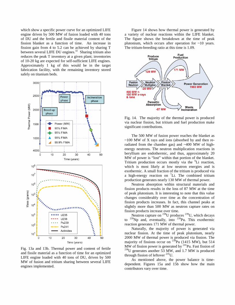
which show a specific power curve for an optimized LIFE engine driven by 500 MW of fusion loaded with 40 tons of DU and the fertile and fissile material content of the fission blanket as a function of time. An increase in fission gain from 4 to 5.2 can be achieved by sharing T between several LIFE DU engines.32 Sharing tritium also reduces the peak T inventory at a given plant; inventories of 10-20 kg are expected for self-sufficient LIFE engines. Approximately 1 kg of this would be in the target fabrication facility, with the remaining inventory stored safely on titanium beds.
Fig. 13a and 13b. Thermal power and content of fertile and fissile material as a function of time for an optimized LIFE engine loaded with 40 tons of DU, driven by 500 MW of fusion and tritium sharing between several LIFE engines implemented.
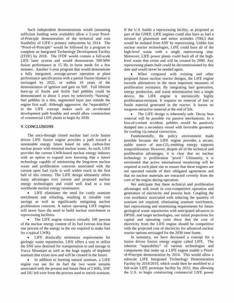
Figure 14 shows how thermal power is generated by a variety of nuclear reactions within the LIFE blanket. The figure shows the breakdown at the time of peak plutonium, which occurs after operation for ~10 years. The tritium-breeding ratio at this time is 1.09.
Fig. 14. The majority of the thermal power is produced via nuclear fission, but tritium and fuel production make significant contributions.
The 500 MW of fusion power reaches the blanket as
~100 MW of X rays and ions (absorbed by and then re-radiated from the chamber gas) and ~400 MW of high-energy neutrons. The neutron multiplication reactions in beryllium are endothermic, and thus, approximately 20 MW of power is “lost” within that portion of the blanket. Tritium production occurs mostly via the 6Li reaction, which is most likely at low neutron energies and is exothermic. A small fraction of the tritium is produced via a high-energy reaction on 7Li. The combined tritium production generates nearly 130 MW of thermal power.
Neutron absorption within structural materials and fission products results in the loss of 87 MW at the time of peak plutonium. It is interesting to note that this value changes considerably over time as the concentration of fission products increases. In fact, this channel peaks at slightly more than 500 MW as neutron capture rates on fission products increase over time.
Neutron capture on 238U produces 239U, which decays to 239Np and, eventually, into 239Pu. This exothermic reaction generates 171 MW of thermal power.
Naturally, the majority of power is generated via nuclear fission. At the time of peak plutonium, nearly 2000 MW of thermal power is produced via fission. The majority of fissions occur on 239Pu (1415 MW), but 514 MW of fission power is generated by 241Pu. Fast fission of 238U generates another 53 MW, and 1.7 MW is produced through fission of leftover 235U.
As mentioned above, the power balance is time-dependent. Figures 15a and 15b show how the main contributors vary over time.

Fig. 15a. Although fission of 239Pu provides the majority of the thermal power, other isotopes also undergo fission. Fig. 15b. In addition to fission, other reactions make a significant contribution to the total thermal power.
When the 238U is significantly depleted, after
approximately 40 years, the fusion neutrons are preferentially utilized for the purpose of burning down the actinides that have been bred in the nuclear fuel as well as to produce tritium for the fusion targets. Additionally, neutrons are lost to absorption in some of the fission product poisons. Since LIFE is a driven, subcritical system, these losses do not result in the shutdown of the power plant, as would be the case with a critical reactor. It is expected that with SHC fuels (and possibly with advanced TRISO-based fuels), LIFE will be able to achieve actinide burn-up of more than 99% from the initial fuel load without reprocessing. With a fission energy content of approximately 1 MW/day per gram, a thermal conversion efficiency of 43%, and a laser efficiency of 10%, LIFE engines would provide a net electric output of ~1 GWe-year per MT of fuel loaded into the LIFE engine.
Even the (relatively) low fusion yield/gain expected from the first HSI targets on NIF would provide an attractive LIFE system. The thermal power curve shown in Figure 15a for optimized LIFE engines that share
tritium could be generated by the 37.5 MJ anticipated from indirectly driven HSI targets with NIF operating at 1.4 MJ of 350-nm laser energy. As shown schematically in Figure 16, if operated at 13.3 Hz, with a 10% DPSSL, this performance would provide 500-MW fusion and generate 900 MW of net electric power for ~40 years from a LIFE engine fueled with 40 metric tons of DU.
Fig. 16. Schematic representation showing the energy and power flow for a LIFE engine loaded with 40 metric tons of DU in SHC fuel, driven by 500 MW of fusion provided by the fusion yield expected from NIF target performance (37.5 MJ). Tritium sharing is assumed.
A stand-alone LIFE engine (i.e., one that is self-
sufficient in tritium) fueled with 40 metric tons of DU-loaded SHC fuel would still achieve 99% burn-up over the same period, but the fission gain would now be limited to ~4. Consequently, to achieve a 1000 MWe or greater net electric power output, the fission blanket would have to be driven by a larger fusion yield. Since the HSI yield curves are non-linear in laser energy, a 35% increase in laser energy (from 1.4 MJ to 1.88 MJ) would double the HSI yield to 75 MJ, and at 13.3 Hz, this 1000 MW of fusion power LIFE option would provide 4000 MWth and 1429 MWe.
The LIFE design is inherently safe. Decay heat removal will be possible via passive mechanisms. In a loss-of-coolant accident for the pebble-based LIFE systems, pebbles would be passively dumped into a secondary vessel with favorable geometry for cooling via natural convection. (See Reference 33 for a detailed safety analysis of the LIFE engine).
Figure 17 shows the benefit possible with a molten salt/liquid fuel LIFE system.31 By continuous removal of fission products with on-line chemical filtering and processing, a U/Th (or SNF/Th) system results in a “burn-down” period that is considerably shorter than for the solid-fuel option (compare with Fig. 13a). Perhaps the biggest advantage inherent to a molten salt fuel is the elimination of radiation damage as a consideration in fuel design. The liquid fuel option, however, has the drawback, compared to solid fuel options, of decreased

proliferation resistance because of the online chemical filtering and processing required.
A key issue with the molten salt fuel option is the solubility of Pu within the salt. Additionally, the rare earth (RE) elements, which are produced directly in the fission process, behave chemically like Pu. Thus, it is the combined concentration of Pu and RE elements that must be monitored and controlled. It will be necessary to remove RE elements. Even with RE removal, the Pu concentration may exceed the solubility limit. To avoid Pu precipitation, one can reduce its concentration by running with a mixed fuel salt. Specifically, running with a mixture of UF4 and ThF4 is suggested. The 232Th as well as the 233U that is produced from it both compete for thermal neutrons, thereby reducing the 239Pu production rate. Operation with an equimolar mixture of U/Th reduces the peak 239Pu concentration by more than a factor of two.
0
250
500
750
1000
1250
1500
1750
2000
2250
0 10 20 30 40 50 60 70
Ther
mal
pow
er (M
W)
Time (years) Fig. 17. Thermal power as a function of time for a molten salt LIFE engine loaded with 40 tons of Th and U dissolved in LIF (76% LIF, 18% ThF4, 6% UF4) driven by 500 MW of fusion.
The performance shown in Figure 17 is the initial
study of a molten salt option for LIFE, and we expect that a U/Th (or SNF/Th) system with continuous replenishing of the fuel could provide fission gains of 8 to 10. This would mean that even with the NIF target performance of 37.5 MJ, a molten salt LIFE system could provide 3000 to 4000 MWth. II.B.3. Final fuel disposition with LIFE
The final level of fuel burn-up can be adjusted to
meet nuclear waste repository and safeguards requirements. Table I shows the actinide content of the nuclear waste at the end of life of a LIFE power plant operating on 40 MT of DU. For burn-up of 99% and
greater, less than 10 kg of actinides would be left for each MT of fuel burned in LIFE. In the case of 99% burn-up, the final fuel composition contains less than 10 kg of actinides per MT of fuel burned, of which the vast majority is in the form of 246Cm. As shown in Table 1, the quantities of weapons-attractive actinides such as Pu and Am are miniscule, as is the remaining amount of long-lived Np. In fact, the spent fuel qualifies for DOE attractiveness Level E, the lowest categorization in the DOE safeguard tables.34,35 This compares quite favorably to the 970 kg of actinides that remain in the SNF for each MT of fuel burnt in a typical LWR at refueling time. These advantages, together with the fact that only 40 MT are required as input fuel for a LIFE engine fueled by DU operating for 50 years (versus 900 MT for a current generation LWR generating the same power over the same period of time) have significant implications for the potential utilization of geological waste repositories. Our calculations show that LIFE could extend the useful capacity of the existing DOE Yucca Mountain repository by as much as a factor of twenty.
TABLE I. Actinide content of approximately the 40 metric tons of spent DU fuel from the LIFE engine of Figure 13 after 90, 95, 99 and 99.5% burn-up. For the 99.5% burn-up, the actinide content is less than 10 kg per metric ton of initial DU.
In this scenario, prior to packaging, LIFE pebbles
would initially be cooled for several months to five years in a relatively high-temperature cooling fluid such as flinak (LiF + NaF + KF). After this initial cooling period, the spent TRISO fuel from a single LIFE engine, assuming that the machine was fueled with 40 metric tons of DU, could be contained in ten to eleven 6-m containers such as those presently utilized for interim storage of existing LWR nuclear waste. Once the pebbles are packaged, the surface of the package must be kept cool during interim storage, transport and eventual emplacement underground. These containers are assumed to sit horizontally in a square flow channel (4.2 × 4.2 m) with a closed-cooling air system. A cooling air velocity of 1 meter per second corresponds to a volumetric flow rate of 695 cubic meters per minute, with an assumed entrance temperature of 25°C and an exit temperature of 60°C. The

calculated maximum temperature inside the fuel mass is 260–360°C. The surface temperature of the metal container is about 150°C, and the temperature at the fuel container interface is about 160°C, well below the temperature at which intermetallic phases deleterious to long-term corrosion performance precipitate in Ni-Cr-Mo alloys such as Alloy C-22.
Following the initial interim storage and cooling at the reactor site, a geological repository similar to Yucca Mountain could be used for long-term storage or disposal. The size of a geological repository needed to accommodate a entire fleet of LIFE engines (with the same generating capacity as our current LWR fleet with a once-through fuel cycle) will be approximately ~5% of that required for disposal of LWR SNF in a geological repository similar to Yucca Mountain. A comparison of once-through LWR and LIFE fuel cycles, based upon electrical generating capacity and upon the mass of SNF generated is shown in Figure 18.
Fig. 18. Due to its ability to achieve higher levels of burn-up, LIFE extends the useful service life of deep geologic repositories by as much as a factor of twenty.
In this comparison, each system was assumed to have
an approximate 50-year service life: LWR = 1.2 GWe per 900 metric tons of heavy metal (MTHM) waste; LIFE = 1.0 GWe per 40 metric tons of MTHM waste. Here, it is assumed that the demand will be 2 TWe in 2100 with half of that capacity supplied by LIFE engines (see Section “III. LIFE Scenarios”), that the inventory of LWR SNF in 2007 is 55,000 MTHM, and that the inventory in 2030 reaches approximately 110,000 MTHM, which is consistent with a SNF discharge of 27 MTHM every 18 months from each operating LWR in the United States.
The same comparison, but based upon the geological repository capacity required for the discharged spent fuel is shown in Figure 19 and assumes that approximately
90–95% of the statutory repository capacity is used for SNF from commercial power reactors or LIFE engines. LIFE’s more complete burn also generates less TRU per GWe than LWR.
Fig. 19. LIFE’s more complete burn generates far less plutonium and transuranic waste per reactor (approximately 1 GWe) than typical LWR.
Introduction of a LIFE fuel cycle would be expected
to significantly reduce the need for geological repositories compared with the once-through LWR fuel cycle. The life cycle cost quoted by the President to Congress in 1992 for a single repository was approximately $58 billion and is currently estimated at more than $90 billion. Clearly, the development cost of LIFE technology would be far less.
The LIFE engine can be utilized to burn not only fertile fuels such as DU, but also fissile materials such as excess WG-Pu or HEU. It is also interesting to note that these fuels can be burned directly in a LIFE engine without the need for MOX fuel fabrication. Figure 20 shows the power curve characteristics of a LIFE engine fueled with 7 tons of WG-Pu and powered by 375 MW of fusion (e.g., the same NIF-like yield expected from early NIF experiments with HSI targets driven at 10 Hz) to provide 3000 MWth for about 5 years. As can be seen in Table II, at the end of life, the initial 7 MT of Pu have been converted to just a few mg of Pu and minimal

quantities of other minor actinides. Table III shows a summary of the performance characteristics for the various LIFE engines discussed above.
Fig. 20. Power curve for a LIFE engine loaded with 7 metric tons of WG-Pu with a blanket gain of 8. The TRISO kernel composition was 80 wt. % ZrC and 20 wt. % Pu, with 400 wt. ppm B as burnable poison.
TABLE II. Actinide content of LIFE spent fuel starting from 7 tons of WG-Pu.
An important aspect of a LIFE engine is the fact that
there is no need to extract the fission fuel from the fission blanket before it is burned to the desired final level. As a result, except for fuel inspection and maintenance process times, the nuclear fuel is always within the core of the reactor, and no weapons-attractive materials are available outside at any point in time. However, an important consideration when discussing proliferation concerns associated with any nuclear fuel cycle is the ease with which reactor fuel can be converted to weapons usable materials, not just when it is extracted as waste but at any point in the fuel cycle. Although the nuclear fuel remains in the core of the engine until ultra-deep actinide burn-up is achieved, soon after start up of the engine, once the system reaches full power, several tons of fissile material is present in the fission blanket (see Figure 13b). However, this fissile material is widely dispersed in millions of fuel pebbles, which are easily tagged as individual accountable items and thus hard to divert in large quantities. In fact, for the LIFE configuration
described in Figure 13a, the 40 MT of DU are initially loaded into 15 million fuel pebbles, with only 235 mg of Pu in each pebble at peak Pu concentration time. To obtain a significant quantity (SQ) of fissile material (defined as 8 kg for 239Pu) 34,000 pebbles would be required. Moreover, our calculations show that such a collection of pebbles generates about 10,000 rad/hr at 1 m and is thus well beyond self-protecting (defined as a dose rate of at least 1 Gy/hour [100 rad/hour] at a distance of 1 meter).34 It is interesting to note that at the end of the burn cycle, the full collection of pebbles contains less than one SQ of 239Pu.
III. LIFE SCENARIOS
A scenario in which LIFE plants could start to be
introduced into the U.S. economy by 2030 has been examined (see Section “IV. LIFE development pathway: Meeting the technical challenges”) and the question asked, what would be required to supply 1000 GWe, or approximately 50% of the estimated U.S. electricity demand, by 2100?
In building these scenarios, it is interesting to note that at present, the U.S. supply of DU is approximately 550,000 tons. If burned in LIFE engines, this would generate approximately 550 TWe-yrs of power. If estimates that the total U.S. electricity demand could reach ~2TWe by 2100 are realized, the current stockpile of DU alone could supply the total U.S. electric demand for nearly 300 years. In addition, as described in the previous section, a significant advantage afforded by the combination of fusion and fission is the fact that a LIFE engine can be used to burn existing and future inventories of SNF from LWRs. At present, in the U.S. alone, the current inventory of SNF in temporary storage at reactor sites is roughly 55,000 MT. The current LWR fleet generates an additional 2000 MT per year.
In this scenario, the LIFE engines would eliminate the 190,000 MT of SNF by about 2250 while simultaneously meeting the U.S. electricity demand. If instead, a policy decision was made to reprocess SNF into fuel streams of transuranic waste (TRU) and U that could then be burnt in LIFE engines, the same electricity would be generated, but the entire accumulated TRU waste (generated by past and future LWRs) would be eliminated by 2100. The reprocessing plants required for this scenario could then be decommissioned. Figure 22 shows a comparison of the quantity of accumulated actinide waste that must be disposed of in a geologic underground repository as a function of time for various scenarios, including continuing with a once-through fuel cycle through the end of the century. Clearly, LIFE scenarios that burn reprocessed or un-reprocessed SNF are more attractive than a once-through fuel cycle.

TABLE III. A summary of fusion and fission performance characteristics for various LIFE engines. Thermal-to-electric conversion efficiency is assumed to be 43%, and the laser efficiency is assumed to be 10% for all systems.
It is also important to point out that the 1,500,000
MT of DU accumulated from the uranium enrichment process required to power LWRs through the end of the century would subsequently provide more than 1500 TWe-years of electricity if burned in LIFE engines. In short, LIFE could supply U.S. electricity needs for more than 1,000 years by burning the two waste streams (DU and SNF) generated by the operations of the past, current, and future LWRs and ALWRs.
In the United States, nuclear energy policy has considered programs such as the Global Nuclear Energy Partnership, or GNEP. GNEP could, in principle, achieve the very high levels of burn-up that are expected for LIFE engines, however, it would require both enrichment at the front end of the fuel cycle and multiple (~10) fuel reprocessing steps. LIFE would obviate the need for fuel enrichment and would not require fuel reprocessing.
Fig. 21. A scenario for transition from a LWR fleet to LIFE engines, with no LWR plants built after 2035. In this scenario, 50% of the projected U.S. electricity demand (1 TWe) would be supplied by LIFE engines burning DU and/or SNF by 2100.

Fig. 22. Quantity of actinide waste that must be disposed of in a deep geological repository as a function of time, assuming that future electricity demand will be supplied by conventional LWRs with a once-through fuel cycle, or a fleet of LIFE engines. A Yucca Mountain Equivalent Repository is assumed to have a limit of 70,000 metric tons of initial uranium metal.
In addition to the U.S. scenarios described above, it is clear that LIFE technology offers an attractive pathway for the expansion of nuclear power around the world. As we have discussed, proliferation concerns are greatly mitigated relative to other nuclear technologies, and nuclear fuel is inexpensive and widely available. Moreover, because LIFE is a self-contained closed fuel cycle, and it burns its fuel down to the point where the actinide content of the spent fuel is less than 1%, international geologic nuclear waste repository considerations would be greatly simplified, particularly for countries not willing to build such underground repositories IV. LIFE DEVELOPMENT PATHWAY: MEETING THE TECHNICAL CHALLENGES
There are many technical challenges on the path to
realizing commercial LIFE engines by the year 2030. The key technical challenges associated with the development of a LIFE engine include those related to achieving robust fusion ignition and burn on the NIF, the 10-Hz laser fusion driver, fusion targets, fission fuel and those associated with the operation of the fission engine.
• NIF will execute one laser shot every few hours. A LIFE engine needs to execute on the order of 10 shots per second. This high repetition rate calls for DPSSLs rather than flashlamp-driven lasers. Experts predict that diode costs used in DPSSLs will continue to decrease significantly over the next several years, and many technologies required for DPSSLs have been demonstrated with the Mercury laser system at LLNL.19
• LIFE engines will require several hundred million, low-cost targets per year that must be injected into the center of the LIFE chamber at a rate of 10-15 Hz.
• The LIFE first wall will be exposed to large fluxes of fast neutrons and X rays. Ongoing research in Japan, the EU, and the U.S. is focused on developing new structural steels that are suitable for both fusion and fission reactors, and therefore, also to the LIFE engine environment. Current and near-term ODS ferritic steels offer radiation limits of 150–300 dpa, which correspond to lifetimes of 4–8 years in a 2.5-m-radius LIFE engine driven by a fusion power of 500 MW.
• Researchers are also investigating and producing new forms of fission fuel capable of withstanding extreme environments for increasingly longer periods. In fact, burn fractions as high as 85% have already been achieved in HEU-fueled TRISO that might be suitable for use in LIFE. Completion of LIFE’s energy mission will require high levels of burn-up in fertile fuels, and thus, either development of advanced solid fuels or the adoption of a liquid fuel form.
Because the fusion and fission components of LIFE are technologically and scientifically separable, a LIFE demonstration program can successfully pursue simultaneous advancements in each of the principal technical components without being confined and limited to a linear development program. Specifically, the science and technology for an integrated demonstration of the LIFE engine can be performed at the modular level in appropriately scaled facilities.
The various technical building blocks of the fusion part of LIFE (generation of the laser power, target production, injection and tracking, and the fusion process itself) are in turn functionally separable, and demonstration of the required fusion performance can and would be done independently of the LIFE fission process.
Demonstration of sufficient gain for optimized HSI targets is expected on NIF by 2012. Demonstration of mass production techniques for the fusion targets at required precision and cost scalability can and would be done “off-line.” Similarly, target delivery, tracking and engagement, as well as chamber clearing can be demon-strated with surrogate targets and low-power lasers in separate facilities. The DPSSL technology, final optics fabrication and damage testing will be demonstrated at the modular level with a single 100-kW beamline.
Similarly, since the fission blanket of LIFE is driven by external fusion neutrons, it operates in a deeply sub-critical mode, and its performance can be modeled and predicted independently of the LIFE fusion process.
Ion beam-based accelerated testing will be used to simulate the materials property changes associated with the LIFE neutron flux environment. These simulations, when coupled to advanced theory and modeling, would allow evaluation of candidate first wall and fuel materials.
Such independent demonstrations would (assuming sufficient funding were available) allow a 5-year Proof-of-Principle demonstration of the technical and cost feasibility of LIFE’s primary subsystems by 2014. The “Proof-of-Principle” would be followed by a program to complete an Integrated Technology Development Facility (ITDF) by 2018. The ITDF would contain a full-scale LIFE laser system and would demonstrate 500-MW fusion performance at 15 Hz in burst mode for a few minutes. Another 5-year program that would demonstrate a fully integrated, average-power operation at plant performance specifications with a partial fission blanket is envisaged by 2022, or within 10 years of the demonstration of ignition and gain on NIF. Full lifetime burn-up of fissile and fertile fuel pebbles could be demonstrated in about 5 years by selectively “burning” fuel pebbles in a thin, segmented layer just outside the engine first wall. Although aggressive, the “separability” in the LIFE concept makes such an accelerated development path feasible and would allow construction of commercial LIFE plants to begin by 2030.
V. CONCLUSIONS
The once-through closed nuclear fuel cycle fusion
driven LIFE fission engine provides a path toward a sustainable energy future based on safe, carbon-free nuclear power with minimal nuclear waste. As such, LIFE provides the current LWR-based nuclear energy industry with an option to expand now knowing that a future technology capable of minimizing the long-term nuclear waste and proliferation concerns associated with the current open fuel cycle is well within reach in the first half of this century. The LIFE design ultimately offers many advantages over current and proposed nuclear energy technologies and could well lead to a true worldwide nuclear energy renaissance.
• LIFE eliminates the need for costly uranium enrichment and refueling, resulting in sizeable cost savings as well as significantly mitigating nuclear proliferation concerns. A nation operating LIFE engines will never have the need to build nuclear enrichment or reprocessing facilities.
• The LIFE engine extracts virtually 100 percent of the nuclear energy content of its fuel (versus less than one percent of the energy in the ore required to make fuel for a typical LWR).
• LIFE drastically minimizes requirements for geologic waste repositories. LIFE offers a way to utilize the SNF now destined for transportation to and storage in Yucca Mountain as well as the huge supply of depleted uranium that exists now and will be created in the future.
• In addition to burning natural uranium, a LIFE engine can use for its fuel the two waste streams associated with the present and future fleet of LWRs, SNF and DU left over from the process used to enrich uranium.
If the U.S. builds a reprocessing facility, as proposed as part of the GNEP, LIFE engines could also burn as fuel a mixture of plutonium and minor actinides (TRU) that would be isolated from SNF by reprocessing. Unlike fast nuclear reactor technologies, LIFE could burn all of the high-level waste with a single reprocessing step. Moreover, LIFE power plants could burn all of the high-level waste that exists and will be created by 2090. Any reprocessing plants built could be decommissioned by this date and would never be needed again.
• When compared with existing and other proposed future nuclear reactor designs, the LIFE engine exceeds alternatives in the most important measures of proliferation resistance. By integrating fuel generation, energy production, and waste minimization into a single device, the LIFE engine is intrinsically highly proliferation-resistant. It requires no removal of fuel or fissile material generated in the reactor. It leaves no weapons-attractive material at the end of life.
• The LIFE design is inherently safe. Decay heat removal will be possible via passive mechanisms. In a loss-of-coolant accident, pebbles would be passively dumped into a secondary vessel with favorable geometry for cooling via natural convection.
Fundamentally, the policy environment made possible because the LIFE engine provides a secure, stable source of non-CO2-emitting energy supports nonproliferation. However, despite all of the technical and proliferation advantages, it is clear that no nuclear technology is proliferation "proof." Ultimately, it is envisioned that active international monitoring will be required at each plant site to ensure that these engines are not operated outside of their obligated agreements and that no nuclear materials are extracted covertly from the core of the engine during operation.
We anticipate that these technical and proliferation advantages will result in cost-competitive operation and generation of electricity and process heat. Coupling the cost avoidance associated with reducing the quantity of uranium ore required, eliminating uranium enrichment, fuel reprocessing and minimizing requirements for future geological waste repositories with anticipated advances in DPSSL and target technologies, our initial projections for capital and operating costs show that the cost of electricity from the LIFE engine should be competitive with the projected cost of electricity for advanced nuclear reactor options envisaged for the 2030 time frame.
In summary, we have discussed a concept for a fusion driven fission energy engine called LIFE. The inherent “separability” of various technologies and components that make up a LIFE engine enable a Proof-of-Principle demonstration by 2014. This would allow a subscale LIFE Integrated Technology Demonstration Facility by 2018/2019, which could then be modified to a full-scale LIFE prototype facility by 2022, thus allowing the U.S. to begin constructing commercial LIFE power

plants in 2030. By 2050, LIFE could be providing a substantial fraction of the U.S. electricity demand. By 2100, LIFE engines could be powering most of the U.S. and worldwide energy grid and providing a large fraction of the global electricity demand, hydrogen fuel supply, desalinization plants and industrial processing plants, generating 20 times less radioactive waste (fission products) per GWe than current and future LWRs. Target gains of 25 – 30 with indirectly driven HSI must be demonstrated on NIF, and challenges remain in the development of advanced materials and DPSSL technologies. However, recent progress on NIF at LLNL and on the physics and technologies of inertial confinement fusion, DPSSL technologies and materials for applications in the nuclear environment in the U.S. and elsewhere around the world promise to bring us closer to realizing the longstanding vision of fusion driven fission energy. Starting with a laser fusion driver with a relatively modest gain of 25-30, such a device would be capable of burning large quantities of spent nuclear fuel, natural or depleted uranium or excess weapons Pu to generate gigawatts of thermal power in a subcritical fission blanket. It would therefore provide pathways to energy generation in a closed nuclear fuel cycle and to eliminating the excess inventory of spent nuclear fuel on the way to pure fusion energy.
ACKNOWLEDGMENTS
The authors wish to acknowledge the many
contributions from a large number of scientists and engineers from the NIF and Photon Sciences; Physical and Life Sciences; Engineering; and Weapons Complex Integration Directorates at LLNL. This work was performed under the auspices of the U.S. Department Energy by Lawrence Livermore National Laboratory under Contract DE-AC52-07NA27344.
REFERENCES
1. International Energy Outlook 2007, Energy Information Administration, DOE/EIA-0484. 2. E. H. SIMS, R.N. SCHOCK, A. ADEGBULULGBE, J. FENHANN, I. KONSTANTINAVICIUTE, W. MOOMAW, H.B. NIMIR, B. SCHLAMADINGER, J. TORRES-MARTÍNEZ, C. TURNER, Y. UCHIYAMA, S. J. V. VUORI, N. WAMUKONYA, X. ZHANG, 2007: Energy Supply. In Climate Change 2007: Mitigation. Contribution of Working Group III to the Fourth Assessment Report of the Intergovernmental Panel on Climate Change [B. Metz, O.R. Davidson, P.R. Bosch, R. Dave, L.A. Meyer (eds)], Cambridge University Press. 3. Key World Energy Statistics, International Energy Agency, 2006. 4. J. H. NUCKOLLS, L. WOOD, A. THIESSEN, and G. B. ZIMMERMAN, “Laser compression of matter to
super-high densities: thermonuclear (CTR) applications,” Nature 239, 139 (1972); J.D. LINDL “Inertial Confinement Fusion,” Springer-Verlag 1998. 5. See NTIS document No. DE94016700 (J.T. HUNT, K. R. MANES, J. R. MURRAY, P. A. RENARD, R. W. SAWICKI, J. B. TRENHOLME, and W. WILLIAMS, “Laser Design Basis for the National Ignition Facility.” 6. http://www.iter.org 7. J. D. LINDL, “Inertial Confinement Fusion,” Springer-Verlag 1998. 8. J. D. LINDL, “The physics basis for ignition using indirect-drive targets on the National Ignition Facility,” Phys. Plasmas 11(2), 339 (2004). 9. A. SAKHAROV, Memoirs, Vintage Books, New York (1990) 142. 10. H. A. BETHE, “The fusion hybrid,” Phys. Today 32 (1979) 44–51. 11. N. G. BASOV et al., “Hybrid reactor based on laser thermonuclear fusion,” Soviet J. of Quant. Elec. 17 (1987) 1324–32; L.P. FEOKTISTOV et al., “On a hybrid reactor based on laser thermonuclear fusion” Kvant. Electron. 5(2), 348 (1978). 12. Proceedings of US-USSR Symposium on Fusion-Fission reactors, LLNL Conf-760733, July 13–16, 1976; M. KOTSCHENREUTHER et al., “Fusion-Fission Transmutation Scheme--Efficient destruction of nuclear waste,” Fusion Engin. Des. 84 (2009) 83-88; Y. GOHAR, “Fusion solution to dispose of spent nuclear fuel, transuranic elements, and highly enriched uranium,” Fusion Engin. Des. 58-59 (2001) 1097-101; W. M. STACEY, “Capabilities of a DT Tokamak Fusion Neutron Source for Driving a Spent Nuclear Fuel Transmutation Reactor,” Nucl. Fusion 41 (2001) 135. 13. J. A. MANISCALCO and L. F. HANSEN, “Status of laser driven fusion-fission energy systems,” LLNL UCRL-85150, 1978. 14. G. MICHAELS, Potential Benefits of Waste Transmutation to the U.S. High-Level Waste Repository (and references therein) International Conference on Accelerator-Driven Transmutation Technologies and Applications. AIP Conference Proceedings 346, Vol. 8, 1995. 15. F. VENNERI et al., Disposition of Nuclear Wastes Using Subcritical Accelerator-Driven Systems, The Uranium Institute 24th Annual Symposium, September 8th through 10th 1999, London, United Kingdom, Uranium Institute, pp. 1-23, 1999. 16. W.F. KRUPKE, “Prospects For Diode-Laser-Pumped Solidstate Lasers,” Lasers & Optronics (1988) 70-84. 17. C. D. ORTH, S. A. PAYNE and W. F. KRUPKE, “A diode pumped solid state laser drive for inertial fusion energy,” Nucl. Fus. 36 (1996) 75–116. 18. J. D. CAIRD et al., “Nd:Glass Laser Design for Laser ICF Fission Energy (LIFE),” Fusion Science Technol., submitted (2008).

19. A. BAYRAMIAN, et al., “The Mercury project: A high average power, gas-cooled laser for inertial fusion energy development,” Fusion Science Technol. 52, 383–387 (2007). 20. R. P. ABBOTT et al., “Thermal and mechanical design aspects of the LIFE engine,” Fusion Science Technol., submitted (2008). 21. H. ZHAO and P. F. PETERSON, “Optimization of Advanced High-Temperature Brayton Cycles with Multiple-Reheat Stages,” Nucl. Technol. 158, 145, (2007). 22. M. TABAK et al., “Ignition and high gain with ultrapowerful lasers,” Phys. Plasmas 1 (1994) 1626-34; M.Tabak et al. “Fast Ignition: Overview and Background,” Fusion Science Technol. 49, 254–277 (2006). 23. J. L. LINDL, “Maxwell prize address”, Bulletin of the American Physical Society, Division of Plasma Physics Annual Meeting, 52 # 16, Talk SR1 (2007) 24. S. UKAI and S. OHTSUKA, “Low cycle fatigue properties of ODS ferritic-martensitic steels at high temperature”, J. Nucl. Mater. 367-370, 234–238 (2007); T. R. ALLEN et al., “The Stability of 9Cr-ODS Oxide Particles Under Heavy-Ion Irradiation,” Nucl. Sci. Engin. 151, 305 (2005). 25. J. F. LATKOWSKI et al., “Fused silica final optics for inertial fusion energy: Radiation studies and system-level analysis,” Fusion Science Technol. 43 (2003) 540-558. 26. D. T. FREY et al., “Mass production methods for fabrication of inertial fusion targets,” Fusion Science Technol. 51, 786–790 (2007); D. T. GOODIN et al., “Developing a commercial production process for 500,000 targets per day: A key challenge for inertial fusion energy,” Phys.Plasmas 13, 056305 (2006); R. MILES et al., “LIFE target fabrication research plan,” LLNL report, 2008, LLNL-TR-408722. 27. R. PETZOLDT et al., “Target injection with electrostatic acceleration,” TOFE Meeting, San Francisco, CA. September 2008; D.T. Frey et al., “Rep-rated target injection for inertial fusion energy,” Fusion Science Technol. 47 1143–1146 (2005); R. W. PETZOLDT and K. JONESTRASK, “IFE Tracking and position update,” Fusion Science Technol. 47, 1126–1130 (2005).
28. J. C. BOKROS et al., “Pyrolytic carbon coated particles for nuclear applications,” United States Patent 3298921 (1967). 29. J. C. FARMER, “LIFE materials: Overview of fuels and structural materials issues,” LLNL-TR-407386 Rev 1, 2008. 30. J. J. WHITLOCK, “The Evolution of the CANDU Fuel cycles and Their Potential Contribution to World Piece,” International Youth Congress 2000, Bratslava, Slovakia, April 9–14, 2000, 8 pages; B. HYLAND, G. R. DYCK, “Actinide Burning in CANDU Reactors,” Proceedings of Global 2007, Boise, Idaho, September 9–13, 2007, American Nuclear Society, pp. 1201–1204; H. CHOI, H. J. RYU, “Sensitivity Analysis of a Dry-Processed CANDU Fuel Pellet’s Design Parameters,” Proceedings of Global 2007, Boise, Idaho, September 9–13, 2007, American Nuclear Society, pp. 926-929; T. K. HAM, Y. J. LEE, M. H. SEO, S. K. OH, “Ambidexter-DUPIC: An LWR-MSR Symbiont Operating on an Effective and Efficient Fuel Cycle,” Proceedings of Global 2007, Boise, Idaho, September 9-13, 2007, American Nuclear Society, pp. 885–890; “Discussions of Scheme 1d, DUPIC Fuel Cycle, Advanced Nuclear Fuel Cycles and Radioactive Waste Management,” OECD 2006 NEA No. 5990, Nuclear Energy Agency, Organization for Economic Co-Operation and Development, p. 244. 31. R. W. MOIR et al., “Molten salt fuel version of laser inertial fusion fission energy (LIFE),” Fusion Science Technol., submitted (2008). 32. K. J. KRAMER et al., “Neutron transport and nuclear burn-up analysis for the laser inertial confinement fusion-fission engine (LIFE),” Fusion Science Technol. submitted (2008). 33. P. F. PETERSON et al., “Fission Safety and Regulatory Analysis for Laser ICF Fission Energy (LIFE),” Fusion Science Technol., submitted (2008) 34. IAEA Safeguards Glossary 2001 Edition, International Atomic Energy Agency, pp. 23, 2002. 35. Guide for Implementation of DOE 5633.3B, Control and Accountability of Nuclear Materials, U.S. DOE Office of Safeguards and Security, April 1995.