a survey on coping with intentional interference in satellite navigation … · increasing in the...
TRANSCRIPT

Tampere University of Technology
A survey on coping with intentional interference in satellite navigation for manned andunmanned aircraft
CitationMorales-Ferre, R., Richter, P., Falletti, E., de la Fuente, A., & Lohan, E. S. (2019). A survey on coping withintentional interference in satellite navigation for manned and unmanned aircraft. IEEE Communications Surveysand Tutorials. https://doi.org/10.1109/COMST.2019.2949178Year2019
VersionPeer reviewed version (post-print)
Link to publicationTUTCRIS Portal (http://www.tut.fi/tutcris)
Published inIEEE Communications Surveys and Tutorials
DOI10.1109/COMST.2019.2949178
CopyrightThis publication is copyrighted. You may download, display and print it for Your own personal use. Commercialuse is prohibited.
Take down policyIf you believe that this document breaches copyright, please contact [email protected], and we will remove accessto the work immediately and investigate your claim.
Download date:28.07.2020

IEEE COMMUNICATIONS SURVEYS AND TUTORIALS 1
A survey on coping with intentional interference insatellite navigation for manned and unmanned
aircraftRuben Morales-Ferre, Student Member, IEEE, Philipp Richter, Member, IEEE, Emanuela Falletti, Alberto de la
Fuente, and Elena Simona Lohan, Senior Member, IEEE
Abstract—Intentional interference in satellite navigation isbecoming an increasing threat for modern systems relying onGlobal Navigation Satellite Systems (GNSS). In particular, criticalapplications such as aviation can be severely affected by un-detected and un-mitigated interference and therefore interferencemanagement solutions are crucial to be employed. Methodsto cope with such intentional interference enclose interferencedetection, interference mitigation, interference classification, andinterference localization. This paper offers a comprehensivesurvey of interference management methods developed in thelast four decades by the research community. After reviewing themain concepts of GNSS-based navigation, the interference andinterference management solutions are classified, with a particu-lar focus on the two major threats in GNSS navigation, namelyjamming and spoofing. Mathematical models, comparative tablesfor various interference management solutions, such as detection,localization, mitigation, and classification, as well as comparativenumerical results based on several selected algorithms are alsopresented. We especially focus on algorithms relying on omni-directional antennas, which do not require additional specificantennas to be installed on the aircraft and thus reduce the costsof retrofit and installation.
Index Terms—aviation, drones, GNSS, interference, jamming,meaconing, satnav, spoofing.
I. INTRODUCTION
FOUR decades of Satellite Navigation (SatNav) and theemergence of new SatNav systems have brought in new
challenges in dealing with the interference encountered overthe wireless channels by the receivers employed in the aviationindustry.
The aviation domain is typically divided into two maincategories: manned and unmanned aircraft. The manned aircraftcategory is the one which requires the presence of a human piloton-board of the aircraft, while the unmanned aircraft categoryrefers to the situation when no human pilot is present on-boardand the aircraft is controlled remotely, through the wirelesschannels. The number of the Unmanned Aerial Vehicles(UAVs), popularly known as drones, has been significantlyincreasing in the past five years and business analysis predictthat the drone market worldwide will grow to more than 50
R. Morales-Ferre, P. Richter, and E.S. Lohan are with theElectrical Engineering unit of Tampere University, Finland, e-mail:{ruben.moralesferre,philipp.richter,elena-simona.lohan}@tuni.fi.
E. Falletti is with the Space & Navigation Technologies research area,LINKS Foundation (former ISMB, Istituto Superiore Mario Boella), Turin,Italy; e-mail: [email protected].
A. de la Fuente is with GMV, Madrid, Spain; e-mail:[email protected] received XXX, 2019; revised XXX
billions dollars by 2025 [1]. The number of Global NavigationSatellite System (GNSS) receivers installed on drones by 2025is also estimated to reach 70 millions and to represent morethan twice of the number of GNSS receivers installed in allother professional applications combined, according to a recentGNSS Supervisory Authority (GSA) market report [2].
Navigation is an essential part of a flying aircraft and itwill become even more important in the crowded sky ofthe near future where millions of drones will co-exist withmanned aircraft. Navigation here refers to the joint ability ofcontinuously locating and tracking an aircraft both from theground and from on-board of the aircraft. Continuous accessto the aircraft exact location is needed not only to allow thesafe routing of tens of thousands of aircraft worldwide, butalso to avoid collisions, to facilitate emergency aids, to enablehigher data rates and better broadband access for on-boardentertainment (e.g., through location-based optimization of thecommunication links), and to support future services such asaerial taxis and ad-hoc aerial networks [3].
Satellite navigation, thanks also to the augmentation systemssuch as Satellite-Based Augmentation Systems (SBAS) orGround-Based Augmentation Systems (GBAS), has becomeone of the main technologies of navigation in modern aircraft,supplementing the on-board inertial navigation systems andproviding worldwide en-route, terminal, and lateral/verticalguidance during the final approach [4]. While the avia-tion industry still relies on conventional instruments calledNavigational Aids (NavAids) to ensure a safe navigation, themost precise positioning technology nowadays for aircraftis the satellite navigation technology. Examples of NavAids,listed with references in Table I, are: Distance MeasuringEquipment (DME), Instrument Landing System (ILS), VHFOmnidirectional Range (VOR), and Non-Directional Beacon(NDB).
Satellite navigation systems can be global, referred to asGNSS and able to provide positioning worldwide, or local, suchas Quasi-Zenith Satellite System (QZSS) in Japan. Currently,there are four GNSSs: the US Global Positioning System (GPS),the Russian Glonass, the European Galileo, and the ChineseBeidou systems. GPS and Glonass systems are already fullyoperational. Galileo declared starting the delivery of its InitialServices on 15th of December 2016 and it currently has 26satellites in sky (as of July 2019), with 22 of them already fullyoperational. Beidou also has 25 satellites in sky (as of August2018), with 23 of them operational. According to International

IEEE COMMUNICATIONS SURVEYS AND TUTORIALS 2
Civil Aviation Organization (ICAO) Annex 10 [5], currentlyonly GPS L1 frequency band and Glonass G1 frequency bandare authorized in aviation, although in the future GPS L5 andGalileo E1/E5a frequency bands are expected to be used too.
The number and sources of GNSS interference have beengrowing at an alarming rate in the past few years, as theInternational Air Transport Association (IATA) safety report [6]and the Eurocontrol voluntary Air Traffic Management (ATM)incident report system [4], [7] pointed out recently. The lowpower of the GNSS signals and an increasing dependence ofmany modern wireless systems on satellite-based navigationattribute to that development. For example, within a time spanof only three months (between March and May 2016) and atonly one airport (Manila airport, in Philippines), more than50 GPS interference incidents were reported [8]. In 2017, theGPS receivers on board of several Norwegian aircraft werejammed for an entire week in a small geographical area closedto Russia borders [9]. Again in 2018, jamming incidents havebeen observed in northern Finland and the Finnmark during aNATO military drill and warnings about large-scale GPS signaldisruptions were issued to the civil aviation authorities [10].According to [7], 47 times more GPS outages occurred duringyear 2017 compared to 2014, mainly due to various interferencesuch as spoofing and jamming in the GPS signal.
Fig. 1 illustrates the main scenario under consideration inthis survey: a scenario with a ground-placed interferer which issending signals, shown as red arrow, into the GNSS bands of aGNSS receiver on-board of an aircraft. The ground interferenceis the most typical interference location. If the interferer signalstrength is powerful, the satellite signals, here illustrated indashed lines and coming from the satellites on sky, will bedestroyed by the interference and the receiver on-board of theaircraft will not be able to rely on the GNSS signals.
Interferer
Earth Surface
Jammer/Spoofer Signals
Fig. 1. Illustration of an interference scenario.
The rest of the paper is organized at follows. Section IIdefines the terminology used in this paper, describes how anastute interference management can increase aircraft safety,surveys various navigation solutions used in manned and
unmanned aircraft, and gives a brief overview of SatNavprinciples, including the main functionalities of a GNSSreceiver. Section III gives an overview of the interferenceclasses, with a particular attention to the two main intentionalinterference types, namely jamming and spoofing. Section IIIalso summarizes the related works, especially the existingsurveys, which treat various types of interference. We alsoillustrate in a table-format how this survey brings together,for the first time in the literature, the different aspects ofinterference in SatNav, with focus on aviation applications.Section IV presents generic mathematical models of differenttypes of interference encountered in SatNav as well as a detaileddescription of various intentional interference types. Sections Vto VIII describe the main algorithms proposed in the literatureso far for the detection (Section V), direction finding andlocalization (Section VI), classification (Section VII), andmitigation (Section VIII) of various interference types inSatNav, by pointing out their suitability and limitations whenapplied in aviation domain. Detailed comparisons are providedbetween various algorithms existing in the literature and acomprehensive discussion is included regarding the interferenceclassification, which is a research field not yet thoroughlystudied in the context of SatNav or aviation. Section IXsummarizes the multitude of the performance metrics usedin the literature to characterize various algorithms proposed asinterference countermeasures and points out the fact that nounified analysis is currently available for the different typesof algorithms and interference. We also include in Section IXseveral unified performance studies comparing several selectedalgorithms for interference detection and localization, basedon both simulations and in-lab measurements. The algorithmsselected for these comparative studies are the most promisingones from our extensive literature searches, according to thetradeoffs between complexity, accuracy, and feasibility analysis,under the constraint of being useful in the aviation context.Section X presents the design recommendations for dealingwith interference in SatNav receivers used in aviation, underthe constraint that the complexity of additional receivers to beinstalled on-board of an aircraft must be kept to a minimum.Section XI discusses the open challenges, the main future trendsin navigation for aircraft, and the open research directions inthis field. Finally, Section XII provides the conclusions.
II. SATELLITE NAVIGATION PRINCIPLES ANDTERMINOLOGY
A. The role of SatNav in aviation and how interferencemanagement can improve safety
Aircraft navigation has evolved over the times from magneticcompasses and beacons-based solutions, such as VOR, DME,Tactical Air Navigation System (TACAN), to GNSS and InertialNavigation System (INS) solutions [11]. For example, DMEis used to measure the distance between the aircraft andthe DME station usually located in the runaway. TACANis the combination of VOR and DME systems in a singleground station. A comprehensive overview of all these solutionsis outside the scope of this paper, but Table I summarizesthe main solutions of navigation for aircraft, pointing out

IEEE COMMUNICATIONS SURVEYS AND TUTORIALS 3
additional references where interested readers can find outmore about each of the listed technologies. From the SatNavpoint of view, navigation systems other than GNSS are knownas Alternative Positioning, Navigation, and Timing (APNT)systems. In civil aviation, the major concern is about safety,followed by availability [12]; translated to the SatNav domain,this means that the technology is required to guarantee acertain (very high) degree of reliability and that SatNavis not the sole means for navigation. Thus, civil aviationapplications rely on the use of Augmentation Systems, whoserole is that of improving accuracy via differential correctionsand monitoring the reliability of the information used forPositioning, Navigation, and Timing (PNT) [12], [13]. Theprincipal augmentation system for civil aviation is the SBAS,which offers wide-area coverage (i.e., continental) for en-routeand non-precision approach navigation.
There exist some different SBAS worldwide, which arebroadcast by geostationary satellites. They broadcast primaryGNSS data, which include ranging, integrity and correctioninformation provided by a network of ground monitoringstations. The main purpose of SBAS is to provide integrityassurance, but the use of SBAS corrections also increasesthe accuracy and reduces position errors to less than 1 meter.European Geostationary Navigation Overlay Service (EGNOS)is the European version of this system and the Wide AreaAugmentation System (WAAS) is the United States equivalent.Other countries such as China, Japan, India and Koreahave launched their own augmentation systems or plannedto do so. To support precision approach operations, SBASmust be complemented by another local Differential GlobalPositioning System (DGPS) augmentation, known as LocalArea Augmentation System (LAAS) or GBAS, which relies ona differential/ground network in addition to the GPS receiverson board of the aircraft [14].
The domain of commercial drones is slightly different,more focused on high accuracy and less constrained byregulations [2]. In drone domain, Real Time Kinematic(RTK) solutions are used to improve the position accuracyto centimeter-level. In addition, more recent solutions alsoinclude terrestrial-augmented signals, such as Television (TV),radio broadcast signals or WLAN signals, which are typicallysuitable for low-altitude vehicles only.
What clearly appears is that, as emphasized in Table I,the SatNav solutions are key navigation solutions in modernaircraft.
A consequence of the low power of SatNav systems, andin particular of GNSS signals used in GNSS-based navigation,is their weakness to interferences. For example, a low power(10 dBm) interference radiated by a low cost (10 Euro) jammercan block any GNSS signal within 100 m radius around thejammer, provoking the loss of GNSS navigation. In general,jamming devices can take different shapes and sizes, beingtypically portable/mobile. Civil, mass-market jammers can befed by the car cigarette lighter receptacle or small batteries,their power consumption is relatively low, nevertheless, theymay disrupt GNSS signal reception over distances of tens ofkilometres [15]. Military jammers (electronic warfare units)are commonly high power jammers mounted on vehicles, able
to cover even several thousand kilometres [15].The consequence of GNSS jamming is the unavailability of
GNSS-based navigation, which has multiple negative potentialimpacts on aircraft systems (navigation, Automatic Depen-dent Surveillance-Broadcast (ADS-B) surveillance, etc.), andtherefore operational impacts specially in congested TerminalManoeuvring Area (TMA). The number of unintentional GNSSjamming events is increasing, according to Eurocontrol Volun-tary ATM Incident Reporting (EVAIR) safety bulletins based onvoluntary reports of pilots in Europe. Current mitigation actionimplemented in commercial aircraft consists in the installationof on-board avionics providing less-precise backup navigation,e.g. conventional NavAids and Inertial Reference Unit (IRU)during loss of GNSS. Implementing additional interferencemitigation solutions as those surveyed by us here can enhancethe GNSS receiver performance and improve the safety ofpassengers.The use of conventional NavAids has been forexample studied in the references given in Table I for non-GNSS solutions. Some IRU-based solutions for aircraft weredescribed in [16]. However, these are outside the scope ofour paper, as the focus here is on modern aircraft navigationsolutions, based on GNSS.
Another kind of interference in SatNav is spoofing, namelythe counterfeit transmission of GNSS signals radiated by a user,either intentionally malicious or unintentionally. A spoofer canmake the aircraft to navigate using the counterfeit signal insteadof the true one transmitted by the satellites, thus the aircraftmight be re-routed on a wrong route and might create serioussafety hazards to passengers and pilots. The consequenceof GNSS spoofing [17] is a misleading information, i.e., anintegrity issue, leading to higher severity hazards than jamming.The reported events of GNSS spoofing in aviation are stillrather rare, but more and more spoofing incidents have beenobserved from land observations units over the past years. Thelow incidence of reported spoofing events is also partly due tothe fact that such spoofing events cannot be reported by pilotsbecause the spoofing is not currently detected or monitoredon-board of the aircraft.
Therefore it is crucial to endow the future aircraft with thecapability to detect, localize, mitigate and possibly classifythe presence of a jamming or a spoofing signal. our surveypaper gives a comprehensive overview into these interferencemanagement issues.
In addition to the safety and security aspects, if properinterference management is performed, the reduction of thenumber and duration of GNSS outages, and their associatedtraffic disruption events, will reduce the number and durationof flight delays, diversions and cancellations, and thus it willproduce an increase of capacity.
B. Brief description of SatNav principles
The existing SatNav systems are composed of three segments:Space Segment, Control Segment and User Segment, asillustrated in Fig. 2. The Space Segment comprises the set ofsatellites in the space, while the Control Segment monitors thesatellite operations and uplink (i.e., from ground to the satellite)commands if necessary, such as orbit or time corrections. The
IEEE COMMUNICATIONS SURVEYS AND TUTORIALS 4
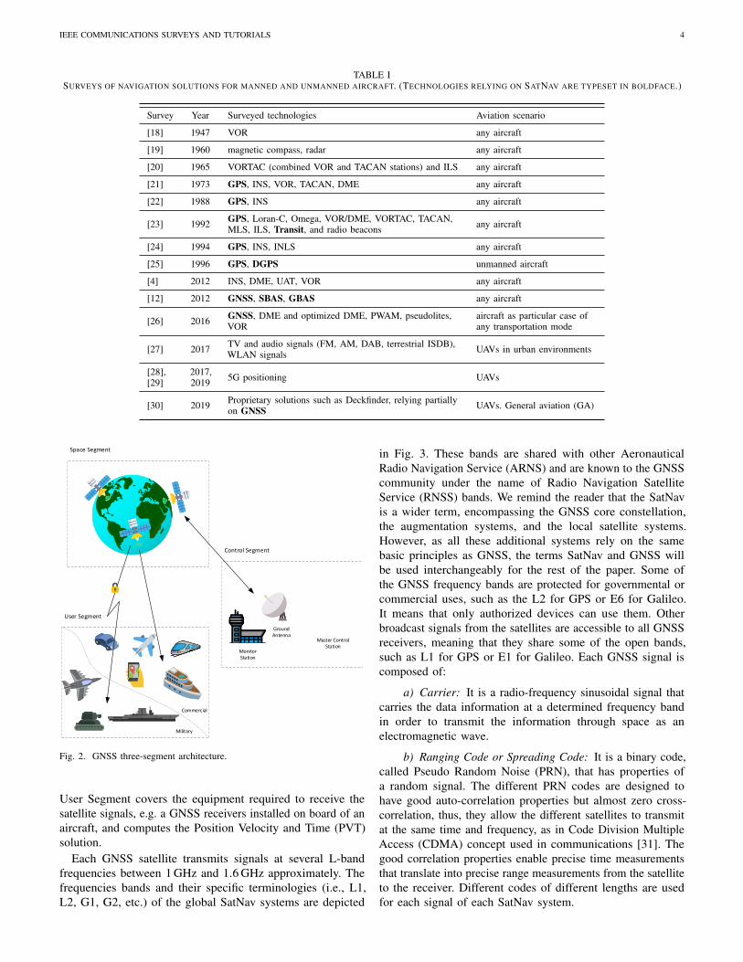
TABLE ISURVEYS OF NAVIGATION SOLUTIONS FOR MANNED AND UNMANNED AIRCRAFT. (TECHNOLOGIES RELYING ON SATNAV ARE TYPESET IN BOLDFACE.)
Survey Year Surveyed technologies Aviation scenario
[18] 1947 VOR any aircraft
[19] 1960 magnetic compass, radar any aircraft
[20] 1965 VORTAC (combined VOR and TACAN stations) and ILS any aircraft
[21] 1973 GPS, INS, VOR, TACAN, DME any aircraft
[22] 1988 GPS, INS any aircraft
[23] 1992 GPS, Loran-C, Omega, VOR/DME, VORTAC, TACAN,MLS, ILS, Transit, and radio beacons any aircraft
[24] 1994 GPS, INS, INLS any aircraft
[25] 1996 GPS, DGPS unmanned aircraft
[4] 2012 INS, DME, UAT, VOR any aircraft
[12] 2012 GNSS, SBAS, GBAS any aircraft
[26] 2016 GNSS, DME and optimized DME, PWAM, pseudolites,VOR
aircraft as particular case ofany transportation mode
[27] 2017 TV and audio signals (FM, AM, DAB, terrestrial ISDB),WLAN signals UAVs in urban environments
[28],[29]
2017,2019 5G positioning UAVs
[30] 2019 Proprietary solutions such as Deckfinder, relying partiallyon GNSS UAVs. General aviation (GA)
Control Segment
Space Segment
Military
Commercial
User Segment
Ground Antenna
Master Control Station
Monitor Station
Fig. 2. GNSS three-segment architecture.
User Segment covers the equipment required to receive thesatellite signals, e.g. a GNSS receivers installed on board of anaircraft, and computes the Position Velocity and Time (PVT)solution.
Each GNSS satellite transmits signals at several L-bandfrequencies between 1 GHz and 1.6 GHz approximately. Thefrequencies bands and their specific terminologies (i.e., L1,L2, G1, G2, etc.) of the global SatNav systems are depicted
in Fig. 3. These bands are shared with other AeronauticalRadio Navigation Service (ARNS) and are known to the GNSScommunity under the name of Radio Navigation SatelliteService (RNSS) bands. We remind the reader that the SatNavis a wider term, encompassing the GNSS core constellation,the augmentation systems, and the local satellite systems.However, as all these additional systems rely on the samebasic principles as GNSS, the terms SatNav and GNSS willbe used interchangeably for the rest of the paper. Some ofthe GNSS frequency bands are protected for governmental orcommercial uses, such as the L2 for GPS or E6 for Galileo.It means that only authorized devices can use them. Otherbroadcast signals from the satellites are accessible to all GNSSreceivers, meaning that they share some of the open bands,such as L1 for GPS or E1 for Galileo. Each GNSS signal iscomposed of:
a) Carrier: It is a radio-frequency sinusoidal signal thatcarries the data information at a determined frequency bandin order to transmit the information through space as anelectromagnetic wave.
b) Ranging Code or Spreading Code: It is a binary code,called Pseudo Random Noise (PRN), that has properties ofa random signal. The different PRN codes are designed tohave good auto-correlation properties but almost zero cross-correlation, thus, they allow the different satellites to transmitat the same time and frequency, as in Code Division MultipleAccess (CDMA) concept used in communications [31]. Thegood correlation properties enable precise time measurementsthat translate into precise range measurements from the satelliteto the receiver. Different codes of different lengths are usedfor each signal of each SatNav system.

IEEE COMMUNICATIONS SURVEYS AND TUTORIALS 5
G2L5 G3
E5a E5b
L2 L1 G1
RNSS
ARNS
RNSS
ARNS
Galileo GPS GLONASSARNS: Aviation Radio Navigation
ServiceRNSS: Radio Navigation Satellite
ServiceBeiDou
G3
B3 B1B2
E1E6
Fig. 3. GNSS frequency bands for GPS, Galileo and Glonass. It also shows which specific bands are used for other Aviation Radio Navigation systems, suchas beacons-based navigation.
c) Navigation Data: It is a message that contains in-formation about the satellites, most importantly being thehealth status, the satellite position information at a giventime (ephemeris), the satellite clock bias, the almanac (areduced-precision ephemeris), and additional complementaryinformation. The navigation message uses a much smaller datarate than the spreading code.
More details about GNSS signals and their composition canbe found for example in [32] and [33]. An unified mathematicalanalysis for all GNSS modulations used in the GNSS openfrequency bands can be found in [34].
The SatNav positioning is based on distance measurementsthrough the so-called trilateration mechanism, when threemeasurements are used, or multilateration mechanism, whenmore than three measurements are used. Assuming that perfecttime measurements are available, we can write the following,
r (k) = c · ∆t(k), (1)
where r (k) is the distance between the k-th satellite and theGNSS receiver, c is the speed of light and ∆t(k) is the time ittakes the signal to travel from the k-th satellite to the receiver.Thus, the true geometric distance r (k) can be computed fromthe signal’s propagation time. The propagation time at its turnsis obtained from the correlation of the incoming PRN codewith its local replica.
The range r (k) in equation (1) is ideal, without error. Inpractice, both the receiver and satellite clocks have certainbiases, deteriorating the range estimate. We denote the receiverclock bias by τu and the satellite clock bias by τs. Furthererrors are caused by the propagation channel, such as therandom delays introduced by the troposphere and ionosphere,multipath delays, etc. Thus, the measured range differs fromthe true geometric range. The measured range from the k-thsatellite to the GNSS receiver is called a pseudorange ρ(k) andit can be expressed by
ρ(k) =
√(x(k) − xu)2 + (y(k) − yu)2 + (z(k) − zu)2 + c · τu + ζ,
(2)where (x(k), y(k), z(k)) and (xu , yu , zu) denote the k-th satellite’sposition and the user position (in Cartesian coordinates),
respectively, and ζ is a lumped sum of the rest of theerrors occurring during the wireless propagation, such assatellite clock bias, the atmosphere effects, the multipath, theinterference, and the background noise. The satellites positions(x(k), y(k), z(k)) are transmitted in the navigation message.Therefore, the only unknowns in the equations are the userposition (xu , yu , zu) and the receiver clock bias τu . Thus, weneed at least four satellites to compute four pseudoranges andto be able to determine the four unknowns of the system ofequations (2). These non-linear equations can be solved byemploying closed-form solutions (e.g. Least Squares), iterativetechniques based on linearisation (e.g. iterative Least Squares)or various types of Kalman filters (e.g., extended Kalmanfilter). The receiver position solution (2) is given in Cartesiancoordinates. Then these Cartesian coordinates are transformedto geodetic coordinates; the geodetic system presents thelocation on the earth by its latitude, longitude, and altitude.For more details about how the user position is determinedand about the various sources of errors in GNSS, the reader isreferred to [32] and [33].
C. Brief description of the main blocks of a SatNav receiver
The main objective of a SatNav/GNSS receiver is todetermine the PVT solution based on the received signalscoming from the constellation of different satellites in view.Fig. 4 shows the block diagram of a typical SatNav receiver.
a) Antenna(s): The antenna is the first element in theGNSS receiver chain. Its aim is to collect the transmitted signalby the satellites and to make it available for the rest of thereceiver blocks. Multiple antennas or antenna arrays are alsopossible in GNSS. A good survey of the desired features forGNSS antenna arrays can be found in [35]. Some authorsconsider the antennas as a part of the receiver front-end block,but in the case of multi-band GNSS, antennas tuned to a certainfrequency band may come with its own front-end, thus we haveplotted antennas and front-end as separate entities in Fig. 4.
b) Front-end: It is the block after the GNSS antenna,typically composed of a band-pass filter, a low-noise amplifier,a frequency converter either to an intermediate frequency or

IEEE COMMUNICATIONS SURVEYS AND TUTORIALS 6
Front-end
Acquisition Module
Tracking Module
Navigation Module
PVTSolution
GNSS Antenna(s)
Pre-correlation Techniques
Post-correlation Techniques
GNSS Receiver
Navigation Techniques
AGC Tracking Module
Front-end Techniques
Tracking Module
Fig. 4. Simplified block diagram of a typical SatNav receiver. The different stages shown in white boxes (front-end, pre-correlation, post-correlation, andnavigation) also reflect our topology of the interference management approaches.
to the baseband, and possibly additional filtering stages (e.g.,anti-aliasing filters).
c) Analog-to-Digital Converter (ADC): The ADC sep-arates the analog waveform from the digital samples andperforms the analog-to-digital conversion. The signal at theoutput of the ADC block is the signal in the so-called pre-correlation domain, i.e., before any correlation is performedat the receiver side. As we will show later on, most of themethods that deal with interference in SatNav are implementedin the pre-correlation stage. Strictly speaking, the ADC alsobelongs to the front-end, but since it plays an important rolein separating the front-end techniques from the pre-correlationtechniques, we decided to emphasize it separately in the blockdiagram of Fig. 4.
d) Acquisition module: The objective of the acquisitionmodule is to determine the satellites in view of the receiverand to calculate a rough estimate of parameters needed inPVT computation, such as the index of the satellites, alsocalled Spatial Vehicles (SVs) in SatNav terminology, the coarsetime-delay estimate from the satellite to the receiver, and thecoarse Doppler shift estimate of the satellites in sky. Theseestimates will be used by the tracking modules as initial values.Acquisition in GNSS relies on correlations between the receivedsignal and several time-shifted and frequency-shifted PRNscode replicas at the receiver. Good surveys about the GNSSacquisition can be found for example in [36]–[38].
e) Tracking module: The main goal of the trackingmodule is to refine the initial time-delays and Doppler shiftsprovided by the acquisition module, and to continuously trackchanges in any of these values. The tracking of a satellite startsonly if the acquisition is successful, as some visible satellitesmay fly at very low orbits with respect to the receiver positionon Earth or be in Non Line of Sight (NLOS) conditions, i.e.,absence of a direct Line of Sight (LOS) between the satelliteand receiver due to the presence of tunnels, buildings, trees, etc.During the tracking stage, accurate time-delay and Doppler shiftestimates from each satellite in sky are continuously obtained,
allowing the GNSS receiver to follow the dynamics of theaircraft. As at least four satellites are needed to form a positionestimate, there should be at least four tracking channels inparallel, each tracking channel corresponds to one satellite.
f) Navigation module: The aim of the navigation moduleis to solve the aircraft PVT solution, based on the valuestracked by the tracking module and combining the informationcoming from all available satellites in sky.
The next section discusses in more detail the differentinterference types in SatNav.
III. INTERFERENCE OVERVIEW
A. Interference definitions and classifications
Interference can be defined as any disruption of an electronicsystem or device due to external electromagnetic emissions ata Radio Frequency (RF) of interest, according to [39]–[41].We remind the readers that the RF bands relevant for GNSSwere shown in Fig. 3.
Interference can be classified according various differentcriteria. We adopt here a classification similar to [39]–[42].This classification is shown in Fig. 5. A top-level classification
InterferencesMan-made Channel-based
Intentional Unintentional
JammingAdjacent Channel
Co-channelOtherMultipaths
Space WeatherSpoofing Meaconing
Atmospheric Scintillation
Fading
Shadowing
Scattering
Doppler Effects
Single-band
Multi-band
Simplistic
Intermediate
Sophisticated
GNSS Repeaters
Crosstalk
Radio Resources Allocation
Inter-modulation Products
LOS+ MultipathNLOS only
Fig. 5. Interference top-level classification.
is according to the source of the interference, namely artificialversus natural interference [40]. In the artificial case, theinterference is produced by various wireless transmitters, whilein the natural case, the interference is due to various wirelesschannel effects. Artificial interference can be further classifiedinto intentional or unintentional interference, according to

IEEE COMMUNICATIONS SURVEYS AND TUTORIALS 7
whether it was generated by a malicious transmitter or not.Intentional interference include jamming, spoofing, and mea-coning. We further categorise unintentional interference intoadjacent channel and co-channel interference. Adjacent channelinterference is due to a RF emission into a different channel thatleaks energy into the channel under consideration, e.g. inter-modulation products. Co-channel interference is caused by anemission of a transmitter that uses the same channel, e.g. radioresource allocation problem or cross-talk. Natural interferenceis due to interactions of the RF wave with with obstacleson the wireless channels (e.g., through reflection, diffraction,refraction, scattering, scintillation, etc.). This can cause multi-path propagation (i.e., delayed and attenuated copies of thesame signal), or ionospheric and tropospheric delays andattenuation. Space weather effects in the ionosphere, causingscintillation, are an other source of natural interference that arespecific for satellite communication and navigation systems.Fading, shadowing, and Doppler effects over the wirelesschannel can also be seen as a form of natural interference, inFig. 5 we collect them under the terminology of Other. Thebottom level in Fig. 5 gives examples belonging to the differentinterference classes. For works on mitigating the effects ofnatural interference we refer to [43]–[45].
The main emphasis of our paper is on intentional interference,as emphasized in Fig. 5. Jamming refers to broadcastinginterference signal(s) deliberately into the frequency bandsof the signal of interest, typically at a higher power comparedto the signal of interest. Spoofing refers to the situation whena transmitter, typically installed on the ground, is sendingcounterfeit signals towards the receiver with the effect oftricking its user. Meaconing is a particular case of spoofing,it refers to re-broadcasting (i.e., ‘copying’) an authenticnavigation signals by a malicious transmitter.
The unintentional interference includes for example out-of-band emissions of other RF systems, that are commonlyharmonics of broadcast systems, but also signal leakage fromUltra-Wideband (UWB) systems, personal electronic devices, orRF systems installed close to the receiver. Many unintentionalinterferences can be still modelled as a ‘jammer’, thus jammingcountermeasures are also applicable in the context of dealingwith unintentional interference.
B. Literature landscape on intentional interference in GNSS
This section introduces the intentional interferences in moredetail and presents briefly the existing works that overview thetopics of jamming and spoofing. Studies around jamming occurin a much wider context than spoofing, as the disruption of aradio link is much easier than manipulating the informationlink carries; whereas spoofing is specific to GNSS.
1) Jamming in the literature: Jamming is the simplest-to-generate attack against SatNav systems among the artificialinterferences. GNSS jammers broadcast an interference signalin one or several of the frequency bands used by the GNSSsignals. This attack can be categorized as Denial of Service(DoS) attack, since the true GNSS signal transmission is notmodified or altered. The true signal is still available but it ismasked by the jammer signal, whose power is usually orders
of magnitude higher than the signals coming from the satellites.The GNSS signals coming from the satellites are below thenoise level, because of the large transmitter–receiver distance(around twenty thousand kilometre) that causes a high signalattenuation.
The legislation regarding the use of jammers has not yetbeen harmonized worldwide. A recent survey [46] showed thatin Europe there are active efforts towards making the use andpossession of jammers illegal, but the legal provisions are stillscattered and non-unified, especially at worldwide level.
There is not a single classification for jamming signals.A possible classification is given in [47] and [48], in whichthe jammer signals are split in four classes according to thedifficulty of detecting them. More details on jammer signalstypes will be given in Section IV.
Jamming has been previously studied in various contexts.Surveys on jamming attacks and possible countermeasuresare available in the contexts of Wireless Sensor Networks(WSN) [49]–[52], Multi Hop Wireless Networks (MHWN) [53],Orthogonal Frequency Division Multiplexing (OFDM) com-munications [54] and Long-Term Evolution (LTE) cellularcommunications [55]. Potential benefits of jamming in WSNhave also been surveyed [56].
While works that survey the field of jamming in SatNav arenot available, the studies in [48], [57]–[60] give nonethelessa good overview of issues caused by jamming and potentialsolutions as detailed below.
The authors of [48] address the negative impact of jammingon the GNSS receiver performance and present three classesof jamming detection: at Automatic Gain Control (AGC)level, at digital pre-correlation signal processing level, andat post-correlation domain level. However, no comparativeperformance analysis between these three different detectionclasses is provided, the main take-away message being thatthe interference detection can be done at different stages ofthe receiver.
Gao et al. [57] give a broad overview about increasingthe robustness of GNSS in the presence of jamming anddiscuss INS/GNSS-coupled navigation, spatial filtering, andtime-frequency filtering vector tracking. Again, no comparativeperformance between the different algorithms is given andthe conclusions state that any of the studied approaches isbeneficial for GNSS and they can detect or mitigate jamming.
Jamming mitigation based on beamforming techniques withmulti-antenna GNSS receivers is the focus of [58]. While allthe tested multi-antenna Controlled Radiation Pattern Antenna(CRPA) techniques are shown to be much better than single-antenna techniques, no winning technology among the studiedbeamformers was selected. Amin et al. [59] discuss the use ofsparse arrays and sparse sampling to mitigate jamming in thecontext of GNSS. They use a co-array framework on single andmultiple-antenna/CRPA receivers for improved beamforming,in order to estimate the jamming signal’s Angle of Arrival(AoA) and to suppress it. In [60] the localization of jammersis addressed, and different approaches based on AoA, TimeDifference of Arrival (TDoA), Frequency Difference of Arrival(FDoA) and Received Signal Strength (RSS) were described

IEEE COMMUNICATIONS SURVEYS AND TUTORIALS 8
and compared qualitatively. No quantitative analysis in termsof performance metrics was provided.
2) Spoofing and meaconing in the literature: Spoofing isa more complex attack against SatNav systems than jamming.Spoofing attacks simulate or modify the true GNSS signalsand rebroadcast it back. By doing this, the attacker can modifythe PVT solution at his/her will. The awareness about thevulnerability of satellite positioning to signal forgery datesback to 2001–2003, with the well known Volpe report [61] andthe paper [62]. But it is in the last ten years, since the proof thata spoofer fooling the civil GPS signals can be developed withlow cost components [63], that the public interest has raisedand literature production about GNSS spoofing aspects hassignificantly increased. More details on spoofing signals typesand their mathematical models will be given in Section IV.
In chronological order, references [64]–[71] represent in theauthors’ opinion the most updated technical surveys currentlyavailable on the topic of spoofing. In these works it is possibleto recognise a common approach to address the subject: thetype of forgery is discussed first, by describing a) the possiblealterations induced on the GNSS signals and b) the Hardware(HW) and Software (SW) ways to inject them, together withconsiderations about the technical difficulties to execute theattack. Secondly, the vulnerability of the state-of-the-art signalsand receivers is addressed. Finally, the vast panorama of thecounteracting measures is investigated and classified accordingto various metrics.
Understanding the mechanism for which the spoofer canintroduce false information in the received signal is the firststep to design proper countermeasures. For this reason allthe previous surveys discuss a classification of the possiblecharacteristics of the falsified signal, in terms of:• methods and technologies to generate it [64],• options to inject it in the received signal ensemble [64],
[65],• modifications induced on the the received signal [65],
[69]–[71],• assessment of the level of technical difficulty to carry the
spoofing attack [65], [69], [71].The studies [65], [69], [70] provide the mathematical
formulation of various types of attacks, leading to theirclassification [65], [71]: the major distinction is made betweenmeaconing and various options of spoofing, which basicallydiffer for either the signal content they aim at altering, orthe strategies they implement to achieve their goals. Theclassification adopted here follows, in a slightly simplifiedmanner, the mentioned references.
The complexity of the equipment setup necessary to carry outa GNSS spoofing attack is recognized as a non-negligible factorin the assessment of the potential danger: attacks with high levelof associated complexity are less likely to be implemented on alarge scale, or to low-revenue (under the spoofer’s perspective)applications. In this light, [65], [69], [71] discuss evaluationsof costs/difficulty associated to different kinds of attack.
The vulnerability of a receiver to a spoofing attack isexplicitly addressed in [64], [65], which analyse the condi-tions in which a receiver may be deceived by false signals.Reference [64] investigates the vulnerability of the signal
structure, identifying which signal components could bevictims of forgery, namely the data bits and the pseudorangemeasurements. To obtain its goal, the malevolent spoofer takesadvantage of the vulnerability of the civil GNSS at the signalprocessing level, since the signal structure is publicly known.
The survey [65] identifies the receiver vulnerabilities de-pending on the signal processing stage in which the receiveroperates at the time of the onset of the attack; from that analysis,the tracking stage results the less vulnerable condition for areceiver, while the cold start offers the widest opportunitiesto the spoofer to succeed. This is the reason for whicha feasible spoofing scenario often includes a preliminaryjamming phase, used to force the receiver in a re-acquisitionphase which leaves more room to vulnerability. In this light,[65] highlights the significant difference between trackingreceivers and snapshot receivers; the former continuouslyestimate the frequency, delay, and phase of the signal, i.e.,they extensively use prior knowledge about the signal; onthe contrary the later sample the incoming signal in non-adjacent time windows and use each ordered set of samples toproduce an estimate of the signal parameters. As a consequence,with respect to vulnerability, snapshot receivers behave likethe acquisition stage of tracking receivers, and so they areparticularly vulnerable to spoofing [65].
What is apparent from all the mentioned surveys is that inmost cases vulnerability is a matter of lack of cross-checksand monitoring measures: since spoofing attacks realisticallyleave traces, the winning game should be the implementationof a number of “check points” in the receiving chain, wheredifferent metrics can be monitored in order to extract clues onthe presence of non-authentic signals [40].
Finally, with a remarkable effort of correlating the manyaspects discussed so far, reference [69] presents an instructiveassignment of ‘implementation costs’ to spoofing attacksand defence techniques, also ranking the effectiveness ofeach technique against each attack; in this way a receivermanufacturer should be enabled to decide which spoofingdefence to implement in its receiver, consciously trading-offamong implementation costs, achievable level of protectionand likelihood of the non-protected attacks.
C. Classifications of interference management solutions inGNSS
We start this section with a classification of countermeasuresto GNSS interference and conclude our overview with thepossible countermeasures to interference. The discussion inthis sub-section is also summarized in Fig. 6, which explainsin a visual manner in which sections of this paper we addresseach countermeasure.
One possible classification of the interference countermea-sures found in the literature is the following: a) countermeasuresat the user level and b) countermeasures at the system level.
User-level techniques represent the huge majority, becausethey are built on the algorithms implemented in the receivers, asa product of the designers’ ingenuity. Such techniques are firstidentified as detection or mitigation techniques, where the for-mer category refers to algorithms that focus on discriminating

IEEE COMMUNICATIONS SURVEYS AND TUTORIALS 9
Direction finding (i.e.,
find the direction of the interference)
Localization (i.e., find the location of
the interfererClassification (optional)
Beamforming to null/block the
direction of interferers
Annihilate or remove the interferers (e.g.,
governmental action)
Mitigation (i.e., mitigate the interference effects through
interference mitigation or interference cancellation techniques)
Choose from the following actions (designer dependent)
Direction Finding or Localization
Mathematical Modeling
Addressed in Sec. IV
Addressed in Sec. VI
Addressed in Sec. VII
Addressed in Sec. VIII
Detection stage:
Interference detected?
No additional
action taken
NO
YES
Addressed in Sec. V
Fig. 6. Stages in dealing with artificial interference in Satellite Navigation. These stages are also reflected in the structure of Sections V-VIII of this paper.
between interference and the desired signals without performingcountermeasures, while the latter “neutralizes the detectedspoofing signals and helps the victim receiver to retrieve itspositioning and navigation abilities” [64]. The first stagestowards applying a countermeasure to the interference presentin GNSS are the modeling of various possible interferenceclasses and the interference detection, shown in Fig. 6. The nextsteps, also illustrated in Fig. 6 and ordered from lower to highercapability are direction finding/localization, characterization/classification, monitoring/mitigation.. The classification shownin Fig. 6 is also similar to the one in [70], where the authorsuse detection, characterization/classification, monitoring, andmitigation. The purpose of each of the stages illustrated inFig. 6 is as follows:
a) Interference modeling: refers to the ability of modelingthe interference mathematically, according to certain parame-ters, such as the interference bandwidth, interference carrierfrequency, etc.
b) Interference detection: refers to the ability to detectthe presence of an interferer in the useful signal. The jammerdetection problem can be typically reduced to the classicaldetection problem of a signal in noise [72], [73], where thejammer becomes the ’useful signal’ and the GNSS becomesthe ’noise’. The spoofing detection is a matter of smarter signalprocessing than the jammer detection, based on the idea thatthe perfect forgery is practically unfeasible and the injection ofnon-authentic signals in a receiver leaves traces [74]–[76]. Suchtraces can be detected with astute signal processing methods,as described later in Section V.
c) Interference direction finding: refers to the ability offinding the angles or directions of the interference source. Suchinformation could help for example in blocking all sourcescoming from that particular direction.
d) Interference localization: refers to a more accurateestimation of the interference source, in terms of its accuratelatitude, longitude, and altitude. Knowing the exact location ofthe interferer can enable robust interference removal methods,such as governmental procedures to get rid of the interferencesources coming from that particular location;
e) Interference classification: refers to the ability ofacquiring knowledge about the type and characteristics ofthe interferers (e.g., carrier frequencies, modulation types,etc.). Such knowledge can enable more efficient interferencemitigation algorithms;
f) Interference mitigation: refers to various methods ofdiminishing or cancelling out the interference. This step canbe in fact use in conjunction with any of the above-mentionedsteps, or it can be also applied as a separate step.
We remark that some of the steps illustrated in Fig. 6 can beskipped out completely, according to the designer and to theoperation conditions and assumptions. For example, in the caseof a dual-frequency GNSS receiver where the interferer affectsonly one of the two frequencies, the receiver can operateonly with an interference detection scheme: if the detectorindicates that the interference is present in only one frequencyband, the receiver will switch to a single-frequency operation,otherwise the receiver will operate in a dual-frequency mode.An other example is to find the direction of the Radio FrequencyInterference (RFI) source and suppress its signal throughbeamforming. In that case, localizing the source might notbe necessary anymore.
Among the system-level techniques, it is worth mentioningthe European system Galileo, which plans to introduce anauthentication service in some of its signals, so as to implementa system-level anti-spoofing approach. A description of theprinciples of the cryptographic defence which is at the basisof the authentication services can be found in [70], while [71]offers deeper details on specific techniques, in particular theNavigation Message Authentication (NMA) and SpreadingCode Authentication (SCA) (SCA); it also presents an inter-esting threat analysis, i.e., an evaluation of the robustness ofsuch techniques against a list of types of attack. Also the GPSstandardization committee has recently started to work on thedefinition of an authentication component for its newer L1Csignal, a modernized civilian signal in L1 frequency band.
Another possible classification of interference countermea-sures or management solutions is according to the block dia-gram in Fig. 4, where the classification of the countermeasuresfollow the GNSS receiver stages, namely:

IEEE COMMUNICATIONS SURVEYS AND TUTORIALS 10
• Front-end techniques,• Pre-correlation techniques,• Post-correlation techniques,• Navigation techniques.
In our paper we will group the following sections according tothe top-level classification shown in Fig. 6, and then, under eachsection, we will follow the algorithm classification accordingto the receiver stages shown in Fig. 4, as, in our opinion,such approach gives the clearest understanding to a potentialdesigner regarding the interference countermeasures.
D. Current gaps in the existing literature
Table II summarizes the main existing surveys and articleson GNSS interference management solutions and comparesthe work provided in our survey with existing work. Emptyentries in the table means a not-available or not-applicableinformation. As seen in Table II, typically, the existing surveysfocus on only one of the two main interference types (i.e.,jamming and spoofing) in GNSS and very often only one ortwo steps of the four interference countermeasures illustrated inFig. 6. A few studies cited in Table II also address co-channeland adjacent channel interference in GNSS. Less than onefifth of the listed surveys in Table II focus on aircraft-orientedinterference countermeasures and no literature survey exist, tothe best of the authors’ knowledge, that summarizes the variousinterference types encountered in GNSS and that explicitlydeals with the four stages to counteract this interference, namelydetection, localization, classification, and mitigation. For clarity,we have lumped together the direction finding and localizationalgorithms, as the direction finding can be seen as a particularcase of the localization (when only the interference directionis estimated, but not its exact location).
Ioannides et al. [70] study the impact of jamming andspoofing on critical infrastructure relying on GNSS. Theyalso overview several detection and mitigation measures atreceiver and system-level and they discuss policy and regulatoryactions. However, no performance metrics are investigatedin [70] and no comparative performance analysis betweendifferent algorithms is given. The conclusions in [70] is thatjamming and spoofing are major threats in GNSS nowadaysand that there is a high need in the research communities tostudy and provide efficient countermeasures to them in thefuture.
By contrast with the published related work over the 15last years, as summarized in Table II, our survey addressesin detail various algorithms proposed to deal with any typeof interference in GNSS and discusses their suitability forvarious interference types as well as their suitability to be usedin aviation context. In addition, unified mathematical modelsof GNSS interference and performance comparisons betweenseveral algorithms based on similar performance metrics arelacking from the current literature and our survey also addressesthis lack.
IV. MODELLING ARTIFICIAL INTERFERENCES
Let us consider the signal r(t) reaching a GNSS receiver on-board of an aircraft. Such a signal can be modeled generically
asr(t) = g(t) + j(t) + s(t) + ξ(t), (3)
where g(t) represents the signals of interest for the GNSSreceiver transmitted by the GNSS satellites, j(t) is a possiblejamming signal including adjacent-band interference (e.g.,harmonics from other systems close to GNSS bands) and s(t)denotes a possible spoofing signal. The background noise overthe wireless propagation channel is modeled as AWGN anddenoted by ξ(t).
A. Jamming signal models
According to literature, e.g., [47] and [48], the followingjammer classes can be encountered. The first four classes areclassified according to the difficulty to detect them, from lowestto highest difficulty, while the last one incorporates the jammertypes not fitting in the first four classes.
a) Class I, Continuous Wave (CW) jammers: The sim-plest type of jammers and the most studied ones are thosebased on CW modulation. CW modulations typically refer tosignals with bandwidth up to 100 kHz. CW class includes theamplitude modulated and frequency modulated jammers, andthey typically are the easiest jamming signals to deal with.Class I includes the single-tone and multi-tone jammers. Amulti-tone jammer, see Eq. (5), consists of k = 1, . . . ,K ofsingle tones (Eq. (4)) and is characterized by PJk , fJk and θJk ,the power at the antenna, and the corresponding frequency andphase of the k-th jammer component. In addition, the class Ialso includes single- and multi-tone Frequency Modulation(FM) jammers (cf. Eq. (6) and (7)), for which the frequencyis time dependent. This incorporates βk into the signal model,the modulation index of the k-th tone.
b) Class II, Single saw-tooth chirp jammers: The secondcategory of jammers contains signals whose frequency ismodulated linearly over time. They are constructed by sweepinglinearly through a certain frequency range in a certain timeperiod after which the process is started again at the initialfrequency. They are also known as swept CW signals, or simply(saw-tooth) chirp jammer. As a side note, this type of jammershave a similar mathematical modeling as the signals usedin most radar systems, but with a different carrier frequency.Class II contains linear FM signals (saw-tooth chirps), here alsonamed Single Chirp for the sake of brevity. The Single Chirpis modeled by Eq. (8). The parameters are the jamming powerPJ , the starting frequency of the sweep fJ (at time Tsweep = 0),the minimum and maximum frequency of the frequency sweepfmin and fmax and the sweep period Tsweep, which is the timeit takes the jammer to sweep from fmin to fmax. The variableb = ±1 is a flag determining if we have an up-chirp (b = 1)or a down-chirp (b = −1), θJ denotes the initial phase of thejammer and fq(t) = 2π fJ t + πb ( fmax− fmin)
Tsweept2 is the instantaneous
frequency of the jamming signal.c) Class III, Multi saw-tooth chirp jammer: A third
category of jammers is the category of multi saw-tooth chirps,representing the weighted sum of two or more single-chirpjammers, transmitted at the same time. Class III includesmulti-component linear chirp signals, named as Multi-Chirpin Table III. The parameters of Eq. (8) are: bk , a flag (±1)

IEEE COMMUNICATIONS SURVEYS AND TUTORIALS 11
TABLE IISUMMARY OF RELEVANT WORK ABOUT GNSS ARTIFICIAL INTERFERENCE. THE 3 AND 7 SYMBOLS IN THE SECOND COLUMN CORRESPOND TO THE
REFERENCES LISTED IN THE FIRST COLUMN
Intentional interference in SatNav Unintentional interference in satnav
Relevantresearch papersand othersurveys
Specificfor
aviationYear Jamming Spoofing and
Meaconing/Repeaters
Adjacent-bandinterference/Out-of-band emission andharmonics frequencyinterference
Co-channel interferencein GNSS bands Generic interference type
[77] 3 1971 Passive emitterlocalization
[78] 7 1983Continuous WaveInterference (CWI)interference suppression
[79] 7 1984 Jamming mitigation
[80] 3 1998 Backup systems to dealwith jamming in GNSS
[81] 7 2000 Wideband interferencesuppression
[82], [83] 3,3 2000–2002 Jamming detection andlocalization
[84] 7 2003 UHF/VHF interferencelocalization
[85]–[87] 3,7,3 2005, 2005,2012 Jamming mitigation
[88] 3 2008 Jamming detection
[89]–[91] 3,7,3 2008, 2015,2018 Jamming mitigation
Radar, JTIDS/MIDS andDME/TACANinterference mitigation
[92] 7 2009 Spoofing effect onpositioning
[93] 7 2010Interference assessmentof DVB-T within GNSSbands
[94] 7 2011 Signal characterizationof jammer types
[64] 7 2012Spoofingcharacterization andanti-spoofing techniques
[95] 7 2012LTE harmonicsinterference avoidancein GNSS
[60], [96], [97] 72012, 2015,2017
Interference detection andlocalization for genericRFI interference
[98] 7 2013 Jamming detection andlocalization
[65], [99],[100] 7,7,7 2014, 2017,
2018Spoofing assessmentand mitigation
[101] 3 2016 Jamming mitigation Self-interference fromUAV’s on-board system
[48], [97] 7,7 2016, 2017 Jamming detection
[59], [102] 77 2016, 2017 Jamming directionfinding and mitigation
[103] 7 2016 Jamming localization Spoofing and meaconinglocalization
[68], [69], [71] 7,7,7 2016,2017Spoofing/meaconingdetection, classification,and/or mitigation
[70] 7 2016 Jamming detection andmitigation
Spoofing/meaconingdetection and mitigation
[104] 7 2017
Interference assessmentof LTE for differentclasses of GNSSreceiver
[105] 7 2018 Jamming mitigation
Our Survey 3 −
Jamming detection,localization,classification, andmitigation
Spoofing and meaconingdetection, localization,classification, andmitigation
RF harmonics detection,localization,classification, andmitigation
Wideband detection,localization,classification, andmitigation
Generic interferencemodelling, detection,localization, classification,and mitigation

IEEE COMMUNICATIONS SURVEYS AND TUTORIALS 12
indicating an up or down chirp; fJk the frequency of the k-thchirp and θJk , the initial phase of k-th chirp.
d) Class IV, Chirp signals with frequency bursts: A fourthcategory of jammers is the chirp with frequency bursts, whenthe frequency bursts are used to expand the frequency bandaffected by the jammer. The jamming signals in class IV arealso frequency modulated signals, but the modulating signaltakes more complex functions. The signals of class IV aredescribed by Eq. (9). The main parameter for a class IV jammertype is the instantaneous frequency of the jamming signal fq(t),which typically has a periodic pattern.
e) Class V, Other jammer types: This class of jammerscontains the jammer type not fitting in any of the abovementioned classes, such as jamming signals that are activeonly during repetitive periods of time with an active period ofa pulse called ’duty cycle’ (these are the DME-like or pulsejammers), or narrowband noise jammers.
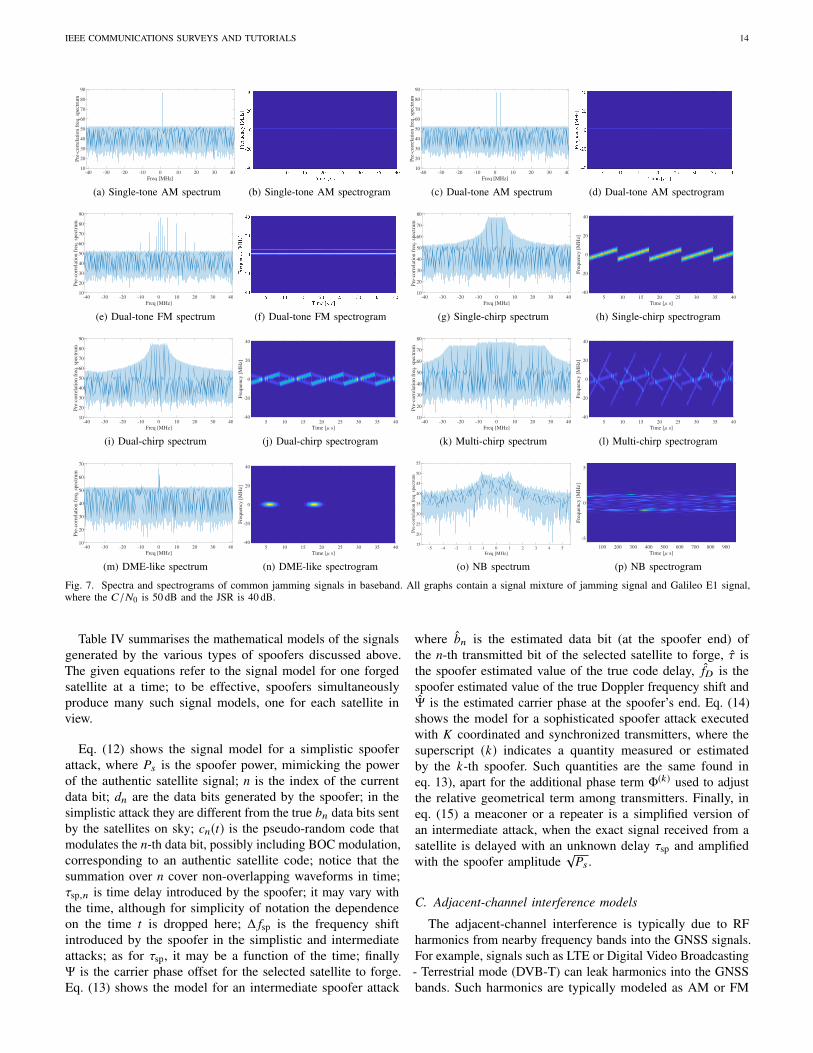
The corresponding baseband models of these jammer classesare given by us in Table III in a unified manner.
An example of the Power Spectrum Density (PSD) and thecorresponding spectrogram of a single Amplitude Modulation(AM)-tone jamming signal at 1.023 MHz is shown in Fig. 7aand Fig. 7b, respectively. An example of the PSD andspectrogram for multi-tone FM is shown in Fig. 7e and Fig. 7f,respectively. The PSD and the spectrogram of an up-chirpjammer with 10.6 MHz sweep range and 8.64 µs sweep period,is shown in Fig. 7g and Fig. 7h. The PSD and spectrogram fora dual-chirp and a multi-chirp signal are illustrated in Fig. 7i,Fig. 7j, Fig. 7k and Fig. 7l, respectively. Comparing the PSDsof the multi-chirp with that of the single-chirp in Fig. 7g,we can observe that their PSDs cannot be distinguished and,thus, we cannot pinpoint the type of a chirp signal based onsolely on the spectrum. This is due to the fact that chirpsare non-stationary signals. Only time-frequency analysis, suchas the spectrogram, can help distinguishing different chirps.From class V type of jammers, we exemplify a pulsed tone (orDME-like) jammer and a narrowband jammer. The DME-likejammer refers to interference signals that are active only duringrepetitive periods of time. The active period of a pulse is calledduty cycle. This jammer type is modeled by Eq. (10), wherepτ(t) is a rectangular pulse of width τ (the duty cycle), fr isthe pulse repetition frequency, δ(t) is the Dirac pulse and ⊗ isthe convolution operator. Fig. 7m and Fig. 7n show examplesof the PSD and the spectrogram for DME-like jammers. Lastbut not least, a narrowband jammer is a generic jammer with anarrowband spectrum, obtained for example by transmitting apreviously modulated RF carrier wave with random amplitudeor frequency changes. The narrowband-noise jammer can bemodeled as shown in Eq. (11), where β is the modulationindex and n(ζ) represents a stationary random process withzero mean and σ2
ζ variance.
B. Spoofing and meaconing/repeater models
The authors of [64] identify three classes of spoofinggeneration techniques, derived from [106]:
a) Simplistic spoofing attacks: The simplest spoofingattacks against GNSS can be carried out by means of a GNSS
signal generator connected to a transmitting antenna. A receivercould be fooled by such signal generator, especially if the targetreceiver is jammed and forced to reacquire the satellites. Suchspoofing attack may be quite expensive, due to the fact that itrequires specific HW such as a GNSS signal generator, whichcan be expensive (e.g., up to hundreds of thousands of dollars)and it is not easily portable. In addition, such attack can beeasily detected, since generally it does not synchronize thespoofing signals with the signals from the GNSS satellites inview. Therefore pseudorange, C/N0 and Doppler jumps canoccur and inconsistencies can be found to signal a spoofingattack. In the civil aviation context, such non-aligned signalensemble received from a distant spoofer could be a possiblescenario because of two reasons: 1) the fine alignment of theforged signals with respect to a very distant user in movementis difficult to achieve; 2) the spoofing attack could addressnon-civilian targets while just erroneously reaching civilianones.
b) Intermediate spoofing attacks: This category containsmore complex attacks than the previous one. They combine aGNSS receiver with a digital processor and a transmitting RFfront-end. The spoofer is able to synchronize the frequencyand align the code-phase between the real and the counterfeitsignals. When the signals from the satellites are tracked by theattacker receiver, the attacker receiver has a perfect knowledgeof both the Doppler shift and the spreading code delay ofthe legit satellite. In principle, any GNSS receiver, properlymodified, can be converted into a spoofer device. This type ofspoofer is able to adjust the signal strength of the counterfeitsignals, in order to simulate signal levels compatible withsatellite transmissions. The aircraft receiver is not able todistinguish the counterfeit signal from the genuine one, sincethe spoofer accurately reproduces the code phase, frequency,and navigation data bits. The navigation bit reproductionrequires a procedure of bit prediction and estimation to performthe attack in real-time. Today an intermediate spoofing attackscan be built with SW parts and RF components readily availableon the market for limited cost; nonetheless, a deep knowledgeof GNSS signal processing is required to correctly setup thesignal processing chain. In the civil aviation context, suchkind of attacks is less probable for the time being, because: 1)the fine signal alignment requires the on-board presence of acumbersome equipment, to receive, process and rebroadcastthe forged signal; 2) if the forgery source is distant from theaircraft, the compensation or the aircraft dynamics can be quitedifficult; 3) GNSS jamming and spoofing monitors should beinstalled and active in the airport area, where either the aircraftcould be still or the take-off/landing paths are more predictable.
c) Sophisticated spoofing attacks: Sophisticated spoofingconsists of a coordinated and synchronized attack carried outby different spoofing devices [106]. This type of attack isthe most complex to implement and deploy, and the mostexpensive and difficult to perform. It is also the hardest todefend against. In this attack, the spoofing devices act as abeamforming antenna array, simulating the different AoAsfor different satellites. This can be accomplished either bykeeping each spoofer fixed and transmitting the signals of allsatellites with appropriately calculated delays compatible with

IEEE COMMUNICATIONS SURVEYS AND TUTORIALS 13
TABLE IIIJAMMING SIGNAL MODELS. THE SUBSCRIPTS IN THE CASE OF SINGLE-COMPONENT SIGNALS ARE DROPPED FOR CLARITY.
Jammer class Jammer Type Jammer baseband model Unknown Parameters
Class I
Single-Tone AM j(t) =√PJ · exp(j(2π fJ t + θJ )) (4) fJ , PJ , θJ
Multi-Tone AM j(t) =
K∑k=1
√PJk exp(j(2π fJk t + θJk )) (5)
fJk , PJk , θJk , and K ,with k = 1, 2, . . . , K
Single-tone FM j(t) =√PJ · exp(j(2π fJ t + β · sin(2π fJ t))) (6) fJ , PJ , β
Multi-Tone FM j(t) =
K∑k=1
√PJk exp(j(2π fJk t + βk · sin(2π fJk t))) (7)
fJk , PJk , βk , and K ,with k = 1, 2, . . . , K
Class II Single Chirp j(t) =√PJ · exp(j(2π fJ t + πb
( fmax− fmin)Tsweep
t2 + θJ ))
=√PJ · exp(j( fq (t)t + θJ ))
fJ , PJ , b, Tsweep, fmin,fmax
Class III Multi-Chirp j(t) =
K∑k=1
√PJk exp(j(2π fJk t + πbk
( fmaxk − fmink )
Tsweepkt2 + θJk )) (8)
fJk , PJk , bk , Tsweepk ,fmink , fmaxk , and K , withk = 1, 2, . . . , K
Class IVChirp Signals
with FrequencyBursts
j(t) =√PJ exp(j( fq (t)t + θJ )) (9) Shape and parameters of
fq (t), PJ , θJ
Class V
DME-like/PulseJammer j(t) =
√PJ pτ (t) ⊗
K∑k=1
δ
(t −
k
frk
)· exp(j2π fJk t) (10) τ, PJ , fJ , fr , K
NarrowbandJammer j(t) =
√PJ cos
(2π fJ t + β
∫ t
0n(ζ )dζ + θJ
)(11)
PJ , fJ , β, θJ shape andstatistics of n(·)
the receiving antenna, or by having each spoofer transmittingthe signal of exactly one satellite and mechanically moving thespoofer around the target receiver. Implementing sophisticatedattacks based on multiple intermediate spoofers is possible,but very hard to manage. In the civil aviation context, aswell as in many other contexts, the likelihood of such anattack is considered particularly low, because of the technicalcomplexity required by the implementation and the logisticproblems implied by the simultaneous operation of multiplespoofing devices, especially in dynamic scenarios.
d) Meaconing: Meaconing is a particular case of spoofing,consisting in the interception and re-broadcast of true GNSSsignals (or the recording and playback) with enough gain tooverwhelm the true signal at the target antenna. This attackdoes not modify the signals, so the target receiver’s PVTsolution becomes the PVT solution of the meaconer, with
a rebroadcasting delay. Although the arrival of the signal atthe target GNSS receiver is delayed, the aircraft receiver mightnot be able to compute its true PVT solution. Through ameaconing attack even an encrypted GNSS signal (such as themilitary L2 in GPS or E6 in Galileo) can be attacked, since ameaconing attack only rebroadcasts the authentic signals. Thiskind of attack is generally easy to implement, since it onlyrequires a few RF components. In the civil aviation context,meaconing has a certain probability of being encountered, notonly as an attack explicitly targeting the aircraft, but alsoas an ‘uninformed’ interference caused with other purposes.For example, if the GNSS repeaters used in hangars are notaccurately shielded electromagnetically, they can be perceivedas ’uninformed’ meaconers in airport areas. Also anti-dronesmeaconers in military sensible zones (e.g., borders, contendedsea areas) could affect civil aircraft along their flights.
IEEE COMMUNICATIONS SURVEYS AND TUTORIALS 14
-40 -30 -20 -10 0 10 20 30 40
Freq [MHz]
10
20
30
40
50
60
70
80
90
Pre
-co
rrel
atio
n f
req
. sp
ectr
um
(a) Single-tone AM spectrum (b) Single-tone AM spectrogram
-40 -30 -20 -10 0 10 20 30 40
Freq [MHz]
10
20
30
40
50
60
70
80
90
Pre
-co
rrel
atio
n f
req
. sp
ectr
um
(c) Dual-tone AM spectrum (d) Dual-tone AM spectrogram
-40 -30 -20 -10 0 10 20 30 40
Freq [MHz]
10
20
30
40
50
60
70
80
90
Pre
-co
rrel
atio
n f
req
. sp
ectr
um
(e) Dual-tone FM spectrum (f) Dual-tone FM spectrogram
-40 -30 -20 -10 0 10 20 30 40
Freq [MHz]
10
20
30
40
50
60
70
80
Pre
-co
rrel
atio
n f
req
. sp
ectr
um
(g) Single-chirp spectrum
5 10 15 20 25 30 35 40
Time [ s]
-40
-20
0
20
40
Fre
quen
cy [
MH
z]
(h) Single-chirp spectrogram
-40 -30 -20 -10 0 10 20 30 40
Freq [MHz]
10
20
30
40
50
60
70
80
90
Pre
-co
rrel
atio
n f
req
. sp
ectr
um
(i) Dual-chirp spectrum
5 10 15 20 25 30 35 40
Time [ s]
-40
-20
0
20
40
Fre
qu
ency
[M
Hz]
(j) Dual-chirp spectrogram
-40 -30 -20 -10 0 10 20 30 40
Freq [MHz]
10
20
30
40
50
60
70
80
Pre
-co
rrel
atio
n f
req
. sp
ectr
um
(k) Multi-chirp spectrum
5 10 15 20 25 30 35 40
Time [ s]
-40
-20
0
20
40
Fre
qu
ency
[M
Hz]
(l) Multi-chirp spectrogram
-40 -30 -20 -10 0 10 20 30 40
Freq [MHz]
10
20
30
40
50
60
70
Pre
-co
rrel
atio
n f
req
. sp
ectr
um
(m) DME-like spectrum
5 10 15 20 25 30 35 40
Time [ s]
-40
-20
0
20
40
Fre
qu
ency
[M
Hz]
(n) DME-like spectrogram
-5 -4 -3 -2 -1 0 1 2 3 4 5
Freq [MHz]
15
20
25
30
35
40
45
50
55
Pre
-corr
elat
ion f
req. sp
ectr
um
(o) NB spectrum
100 200 300 400 500 600 700 800 900
Time [ s]
-5
0
5
Fre
quen
cy [
MH
z]
(p) NB spectrogram
Fig. 7. Spectra and spectrograms of common jamming signals in baseband. All graphs contain a signal mixture of jamming signal and Galileo E1 signal,where the C/N0 is 50 dB and the JSR is 40 dB.
Table IV summarises the mathematical models of the signalsgenerated by the various types of spoofers discussed above.The given equations refer to the signal model for one forgedsatellite at a time; to be effective, spoofers simultaneouslyproduce many such signal models, one for each satellite inview.
Eq. (12) shows the signal model for a simplistic spooferattack, where Ps is the spoofer power, mimicking the powerof the authentic satellite signal; n is the index of the currentdata bit; dn are the data bits generated by the spoofer; in thesimplistic attack they are different from the true bn data bits sentby the satellites on sky; cn(t) is the pseudo-random code thatmodulates the n-th data bit, possibly including BOC modulation,corresponding to an authentic satellite code; notice that thesummation over n cover non-overlapping waveforms in time;τsp,n is time delay introduced by the spoofer; it may vary withthe time, although for simplicity of notation the dependenceon the time t is dropped here; ∆ fsp is the frequency shiftintroduced by the spoofer in the simplistic and intermediateattacks; as for τsp, it may be a function of the time; finallyΨ is the carrier phase offset for the selected satellite to forge.Eq. (13) shows the model for an intermediate spoofer attack
where b̂n is the estimated data bit (at the spoofer end) ofthe n-th transmitted bit of the selected satellite to forge, τ̂ isthe spoofer estimated value of the true code delay, f̂D is thespoofer estimated value of the true Doppler frequency shift andΨ̂ is the estimated carrier phase at the spoofer’s end. Eq. (14)shows the model for a sophisticated spoofer attack executedwith K coordinated and synchronized transmitters, where thesuperscript (k) indicates a quantity measured or estimatedby the k-th spoofer. Such quantities are the same found ineq. 13), apart for the additional phase term Φ(k) used to adjustthe relative geometrical term among transmitters. Finally, ineq. (15) a meaconer or a repeater is a simplified version ofan intermediate attack, when the exact signal received from asatellite is delayed with an unknown delay τsp and amplifiedwith the spoofer amplitude
√Ps .
C. Adjacent-channel interference models
The adjacent-channel interference is typically due to RFharmonics from nearby frequency bands into the GNSS signals.For example, signals such as LTE or Digital Video Broadcasting- Terrestrial mode (DVB-T) can leak harmonics into the GNSSbands. Such harmonics are typically modeled as AM or FM

IEEE COMMUNICATIONS SURVEYS AND TUTORIALS 15
TABLE IVSPOOFING BASEBAND SIGNAL MODELS.
Spoofer class Baseband signal model (per satellite) Unknown parameters
SimplisticSpoofer
s(t) =√Ps
∑n
dncn(t − τsp) exp(j2π∆ fspt + Ψ) (12) Ps , dn , τsp, ∆ fsp
IntermediateSpoofer s(t) =
√Ps
∑n
b̂ncn(t − τ̂ − τsp
)exp(j2π
(f̂D + ∆ fsp
)t + Ψ̂) (13) Ps , τsp, ∆ fsp
SophisticatedSpoofer s(t) =
K∑k=1
√P(k)s
∑n
b̂ncn
(t − τ̂ − τ
(k)sp
)exp(j2π
(f̂(k)D + ∆ f
(k)sp
)t + Ψ̂(k) + Φ(k)) (14)
K , P(k)s , τ(k)sp ,∆ f(k)
sp ,Φ(k)
Meaconer s(t) =√Ps
∑n
bncn(t − τ − τsp
)exp(j2π fD
(t − τ − τsp
)+ Ψ) (15) Ps , τsp
tones, see Eqs. (4) to (7). thus the jamming countermeasuresfor AM/FM tones are also applicable here.
D. Co-channel interference models
Co-channel interference is due to (typically unintentional)interference transmitted into the same frequency band asthe GNSS signals. The most common example here is thewideband interference, for examples coming from the otherGNSS satellites transmitting in the same frequency bands. Suchinterference is typically modelled as an additional Gaussianterm which basically increases the noise variance of the ξ(t)AWGN component of Eq. (3). Other co-channel interferers canbe due to other navigation systems used in aviation, such asDME or TACAN, which share some of the GNSS frequencybands. The DME unintentional interference model is exactlythe same as for the DME-like/pulse jammer, shown in Eq. (10),with the difference that the model parameters τ, PJ , fJ , fr , Kare known in this case.
V. INTERFERENCE DETECTION MECHANISMS
A. Classical detection problem and its applicability
The detection of a single type of interferer can be formulatedas the well-known classical binary detection problem [72],when a received signal may or may not contain an interferencesignal. These two cases are considered as two hypotheses. Thehypothesis H0 stands for the interference-free scenario andhypothesis H1 reflects the case when the interferer is present.
In order to find a decision rule to distinguish between H0and H1 hypothesis, one can rely on the Probability DensityFunctions (PDFs) under H1 and H0 (if known) of a measurabletest statistic. An illustration of PDF is given in Fig. 8. Weremark that the PDF of the received signal samples for H0 isGaussian, but the PDF for H1 may not fit a Gaussian distributionand it is dependent on the interference type. Given that theinterference signal (and thus its PDF) is typically unknown,
-10 -8 -6 -4 -2 0 2 4 6 8 10
Test Statistic Level
0
0.05
0.1
0.15
0.2
0.25
0.3
0.35
0.4P
DF
Pd
Pfa
H0
H1
Threshold
Fig. 8. Illustration of the PDF under H0 and H1 and an example of a detectionthreshold.
the power of the received signal is often used as a test statistic.For H1 the power of the interferer signal i(n) is typicallymuch stronger than w(n). For this reason, the resulting PDFcorresponds mostly to i(n). On the contrary, H0 must fit aGaussian distribution, since r(n) under H0 is mainly noise-like,as a superposition of a weak CDMA signal (i.e., the GNSSsignal) and an Additive White Gaussian Noise (AWGN) noise.
A suitable threshold separates between the two hypothesessuch that the probability of detection Pd is maximized and theprobability of false alarm Pfa is minimized. The probability ofdetection Pd and the probability of false alarm Pfa are
Pd = Pr(T > γ |H1)
Pfa = Pr(T > γ |H0), (16)
where Pr(·) denotes a probability, T denotes a test statistic andγ is a fix or adaptive threshold. The choice of the test statisticis challenging and this challenge limits the applicability ofthis direct hypothesis testing in the interference detection inGNSS. If the PDFs are known under both H0 and H1, the

IEEE COMMUNICATIONS SURVEYS AND TUTORIALS 16
Generalized Likelihood Ratio Test (GLRT), can be applied, asshown in (17)
T =maxθ1
p(r |H1, θ1)
maxθ0
p(r |H0, θ0)
H1≷H0γ, (17)
where p(r |H0, θ0) and p(r |H1, θ1) stand for the conditionalPDFs under H0 and H1 hypotheses, respectively. The θ0 and θ1are the unknown interferer parameters. For example, the workin [107] adopts the binary hypothesis theoretical framework todevelop a detection method for the presence of signal replicasin the samples of the received signal based on a GLRT test.
The classical detection algorithms are rarely applied in thecontext of jamming detection in GNSS in realistic scenariosbecause of the typically unknown jammer PDF. Insteadof applying the classical detection techniques, the GNSSinterference detection algorithms rely on various assumptionsabout the interference type and channel type (e.g., single path,multipath). The next subsections discuss different interferencedetection algorithms encountered in GNSS, based on theirplacement in the GNSS receiver chain of Fig. 4.
B. Front-end detection techniques
Front-end detection techniques typically work for any inter-ference type and are applied before the acquisition, in the firststage of the receiver diagram Fig. 4. In a front-end technique,the signal before the ADC is used. The most encounteredfront-end detection technique is the AGC detector [108]–[110].The AGC maintains the control of the power of the incomingsignal to provide an appropriate power for the quantizer inorder to minimize the quantization losses [108], [109]. TheAGC of a GNSS receiver operates at the ambient noise levels,since the GNSS signal power is very low, due to the largedistance between the SatNav satellites and the aircraft. In thepresence of powerful interferers, and especially for jammers,the AGC decreases its gain to keep AGC output signal levelstable and avoid large fluctuations. This change of the AGClevel can be used to detect an interferer. An AGC interferencedetector typically counts an estimate of the AGC gain overN consecutive samples, and compares it with a predefinedthreshold that corresponds to the interferer-free case. If all theN samples are below a certain threshold, then the interferenceis declared present. The nominal level is manufacturer andantenna specific, and this nominal level needs to be knownto determine an adequate detection threshold. Overall, if thedesigner has access to the AGC values, then the AGC detectionfor jammer detection is straightforward to implement and itdoes not require additional HW elements, thus it is perfectlysuitable for aviation applications.
While the AGC detector can be in theory used also forspoofing or meaconing, in practice the AGC fluctuations dueto a spoofer are much lower than those due to a jammerand they can be easily missed, unless the spoofer power isextremely high. An example of AGC monitoring fruitfully usedto detect a meaconing attack was presented in [111]. However,for the above-mentioned reasons, the effectiveness of the AGCmonitoring for the detection of attack of the intermediate
spoofing type is expected to be more limited. The resultingrecommendation is to perform a careful on-site calibration tocompensate for the non-negligible temperature effect and otherenvironmental conditions, and to use the method in complementwith other monitoring techniques.
C. Detection techniques at pre-correlation level
The vast majority of interference detection methods are pre-correlation techniques (see Fig. 4 for the placement of a pre-correlation algorithms). A pre-correlation technique operateson the signal after the ADC but before the acquisition blockand processes the I/Q samples of the signal. The followingparagraphs summarize the main pre-correlation techniques forinterference detection.
a) PDF detector [110], [112], [113]: This method isbased on the fact that the received signal before despreadingand in the absence of interference should follow a Gaussiandistribution. In the presence of an interferer, such as a jammeror a narrowband/co-channel interferer, the signal’s distributionwill deviate from that of a Gaussian distribution. Examplescan be found in Appendix B, Figure 18.
There are many statistical tests to verify whether a PDF isGaussian-like or not, such as Lilliefors Test [114], Jarque-Beratest [115], Anderson-Darling Test [115], [116], Chi-squaregoodness-of-fit test [116], Kolmogorov-Smirnov test [116], etc.The main drawback of any PDF-based methods is that theyrequire long periods where interferers are present to reliablyestimate the PDF. For highly dynamic jammers as well as forwideband interferers such as spoofers, such methods are likelyto fail. Nonetheless, an example of Chi-square goodness of fittest applied to the baseband signal samples before correlationto detect the PDF distortion in the presence of spoofed signalsis developed in [113].
b) Time Power Detector (TPD) [72], [117]–[122]: TheTPD is known under various names in the literature, suchas Power Law Detector (PLD) [121] or energy detector [72],[122]. This method measures the received signal energy overa short period of time. Its test statistic is given by
TTPD =1
JN
J∑j=1
N∑n=1|r(n + ( j − 1)N)|2ν, (18)
where N is the number of samples of the considered short in-terval, J is the number of short intervals under the observations(thus the signal is observed in total over JN samples) and ν isa positive number that determines the power-law, e.g., ν = 1 forthe square-law detector and ν = 0.5 for the amplitude detector.The measured power, typically normalized by the number ofsamples N and by the noise variance, is then compared witha suitable threshold. If the test statistic exceeds the threshold(TTPD > γ) the interferer is declared to be present. Stitz et al.[119] used TPD test statistic in combination with filter banksand applied it to sub-bands of the original signal. Once thesub-bands containing the jamming signal were detected, theywere removed.
Examples of a TPD detector are given in Appendix B, Fig. 19.The TPD detector is suitable for many interferer types, as longtheir power exceeds that of the GNSS signal. However, TPD in

IEEE COMMUNICATIONS SURVEYS AND TUTORIALS 17
the context of spoofing detection is likely less effective than forjamming detection, because the spoofing strength is expectedto be comparable with respect to the authentic one, in orderto act as much covertly as possible.
A different formulation of the TPD is used in [120] inorder to deal better with spoofing signals. In [120], the powermeasurement metric is used in conjunction with a correlationdistortion metric in order to distinguish among multipath,interference, spoofing, and nominal signal. The joint use ofthe two metrics can compensate the complementary limitationsof each metric used individually: first, power monitoring isprone to false alarms, therefore its detection sensitivity must bereduced so that spoofing signals with a low increase of strengthwith respect to their authentic counterpart go undetected; inthese conditions the correlation distortion monitoring shouldbe able to detect the presence of the non-authentic signal.Secondly, the code correlation function is nearly undisturbed incase of high power attacks, while the power monitoring shouldbe able to detect the significant increase of signal strength.
c) Frequency Power Detector (FPD) [72], [117]: TheFPD is quite similar to the TPD detector, as, according toParseval’s theorem, the average power of a signal in timedomain equals the average power in frequency domain. Theperiodogram is used to estimate the signal’s spectral density forthe FPD. Examples of FPD are shown in Appendix B, Fig. 20.
d) Detector based on Welch’s method [117], [123]:Welch method can be also used to estimate the periodogramand the resulting detector can be seen as a variant of theFPD [117], [123]. Compared to the periodogram, Welch’smethod divides the input signal into overlapping pieces ofa certain length, applies a window to these pieces and thencomputes the periodogram of each of them; this results inaveraged periodograms. The size of each window has to besufficiently small such that the frequency content can beassumed constant for each piece. Examples are shown inAppendix B, Fig. 21.
e) Kurtosis detector [117], [124]–[126]: The kurtosis ofa signal over N observation samples is defined as
Γ =
1N
∑Nn=1(r(n) − µr )
4(1N
∑Nn=1(r(n−)µr )
2)2 , (19)
where µr =1N
∑Nn=1 r(n) is the mean of the signal r(n). Here
r(n) are the incoming pre-correlation samples at the aircraftGNSS receiver. In the absence of jamming, the Kurtosis isclose to 3 (Gaussian distribution). In the presence of a jammingsignal, the Kurtosis may deviate from value 3, the deviationdependents on the type of jamming [117], [124]. Fig. 22 fromAppendix B shows an example of the Kurtosis detector.
f) Notch filter detector [127]–[130]: Notch filters havebeen traditionally used for jamming mitigation, but they havealso detection capabilities, as shown recently [128]. Borio etal. [128] designed an Infinite Impulse Response (IIR) notchfilter whose z-transform is
Hn(z) =1 − z0(n)z−1
1 − kaz0(n)z−1 (20)
and which is adapted using a stochastic gradient approach. Theterm z0(n) is the notch filter’s time-varying zero, whose angle
determines the center frequency of the notch, and ka is thepole contraction factor (a user-defined parameter between 0and 1). The zero z0(n) is adapted to be in accordance with thewith jammer instantaneous frequency in the complex plane.Its magnitude |z0(n)| can be used as detection metric. Again,an appropriate threshold must be found to distinguish theinterference-free case from the jammer present case.
g) Detection based on multi-antenna arrays [131], [132]:This method consists on using the information provided bymore than one antenna to detect the interference. A detectorbased on combining the signal from an antenna array withtwo Right Hand Circular Polarized (RHCP) antennas spacedat λ/2 in GPS L1 band was proposed in [131]. Antenna-basedsolutions are also discussed in Section VIII-A as they can alsobe employed for interference mitigation, but they are not verypractical in the context of an aircraft, as they would increasethe costs of the on-board equipment.
h) Hough-Radon Transform (HRT) [133], [134]: TheHRT is a feature extraction method used to detect geometricshapes in images. It can be used to detect the different linesas they occur in time-frequency transforms as the spectrogram(see examples of spectrograms in Fig. 7). Thayilchira et al.[133] and Erkucuk et al. [134] treated this spectrogram as animage, and applied the HRT to detect a chirp-like interferencein the signal. The HRT can be especially useful as classifierfor the different jammers. Nevertheless, to classify the jammertype, the JSR must be high enough so that the resulting imageshows the lines clearly.
i) Singular Value Decomposition (SVD) detector [135]:The decomposition of the covariance matrix of the receivedsignal in singular values, so-called SVD, and their analysisis the basis of this detector [135]. Studies in [135] show thatthe SVD detector has a good performance for CW jammers,but completely fails for chirp jammers. Aside from this, itsperformance is poor at low JSR.
D. Detection techniques at post-correlation or link levelThese techniques make use of the signal after the correlation
with the reference code of a particular satellite, thus, theyfocus on a satellite-receiver link at a time. They are commonlyimplemented in the tracking module, as they use outputs of thecorrelators (recall Fig. 4). Nonetheless, they may additionallyuse the pre-correlation signal. Post-correlation analysis iswidely the preferred and most powerful approach for spoofingmonitoring. The reason for this is evidently in the structure ofthe spoofing signal, which intrinsically offers features suitablefor acquisition and tracking. The following paragraphs listthe various post-correlation detection techniques found in theliterature.
a) Power Distortion Monitoring (PDM) [120]: A methodcalled PDM was studied in [120]. It monitors both the powerand the correlation function in order to detect sudden changes.The changes in power and the distortion of the correlationfunctions provide complementary information that not onlyallows to detect the presence of a jamming signal, but also thepresence of GNSS multipath or spoofing. While jamming wasdetected reliably in [120], the authors noted that their methodtended to mistake spoofing for jamming.

IEEE COMMUNICATIONS SURVEYS AND TUTORIALS 18
b) Multi-correlator banks [136]–[139]: The apparentsimilarity of a counterfeit signal with a signal replica generatedby a multipath reflection is the reason for the adaptation ofmultipath mitigation techniques, such as multi-correlator banksto spoofing detection and monitoring. Examples of multi-correlator bank-based algorithms include the multiple trackingloops proposed in [137], the Spoofing Estimating Delay LockLoop (SEDLL) [136] or the vector tracking loops investigatedin [138]. Often, this family of techniques is indicated withthe name of vestigial signal defence, as it aims at trackingreplicas of the correlation peak aside the principal one. Multi-correlators banks suffer from high computational load, linearlyproportional to the number of tracking channels (e.g., in a multi-constellation, multi-frequency receiver it may easily reach onehundred or more tracking channels).
c) Multi-Correlator output with Auto Regressive modelling(MCAR) [88]: is based on forming multi-correlator outputs andanalysing them through an Auto-Regressive (AR) modelling.The assumption is that the variances of the correlator outputsincrease with the presence of a jammer. Only continuous waveand narrowband interference were studied with this methodin [88] and its applicability to other interference types is yetunknown.
d) C/N0 monitoring [140]–[142]: The C/N0 is an im-portant measure of the performance of a GNSS receiver, asit indicates undesired decreases in GNSS signal power orthe increases in noise power per tracking channel. However,the C/N0 may change due to several other reasons, such asdeteriorated satellite visibility, which can easily mislead thedetector [64], [76]. A detector based on only C/N0-monitoringperforms rather poor. A jamming signal changes the C/N0 asit contributes to the noise power, thus this allows to detectjamming. Several approaches were studied in the literature: thedifference between C/N0 and effective C/N0 was used in [140],the binary hypothesis testing framework was exploited in [141],assuming the C/N0 normally distributed, and Scaramuzza et al.[142] analysed C/N0 data, in combination with GPS satelliteazimuth and elevation angle and as well roll, pitch, and yawangles. C/N0 monitoring is also a principal indicator forspoofing detection: a sudden upward jump of the C/N0 levelmay indicate the onset of a powerful spoofing attack [64],[74], but also a sudden and concentrated fluctuation of its levelmay indicate a tracking peak shifting from the authentic to thefake signal [74], [76]. Continuous C/N0 monitoring can beconsidered a must-to-have process in an anti-spoofing receiver,although it cannot be the sole means for interference detection.
e) Absolute power monitoring [64]: The monitoring ofthe absolute receiver power of each PRN channel as a method todetect spoofing is discussed in [64], where it is demonstratedwith theoretical considerations that such a method can bewidely more robust than the C/N0 monitoring. Although notexplicitly indicated in the paper, the TPD detector appliedto the post-correlation samples is a candidate method toimplement absolute power monitoring. However, the relativelyhigh dynamic range of the GNSS signal strength may limitthe achievable performance of the monitoring algorithm.
f) Support Vector Machines (SVM) [143]: The SVMapproaches can act both as detectors and as as classifiers
and can be applied both in pre-correlation or post correlationstages in a GNSS receiver [143], but they are more commonin the post-correlation stage. The studies in [143] focus onnarrowband and wideband jammers with JSR between 5 and25 dB and estimate the training time it takes for the SVM-basedclassifier to reach 100% monitoring precision (i.e., between0.75 ms and 60 ms).
g) Signal Quality Monitoring (SQM) detector [144],[145]: On the upper side of the complexity line, SQMtechniques probably offer the highest sensitivity and thesmallest vulnerability to spoofers: they are intended to monitorthe distortion of the received signal induced by a non-authentic source, by applying metrics often originally developedfor detecting multipath conditions. The basis of the SQMapproaches is the observation and statistical characterisationof cross-correlation samples between the received signal andlocal replicas delayed by opportune amounts [113], [146],[147]. The quantification of the deviation of such samples fromthe nominal correlation function is the test statistic adoptedto detect the presence of counterfeit signals. A well-knownmethod belonging to this class is the ratio test proposed forspoofing detection in [148]; other approaches belonging tothe same class are the Goodness of Fit (GoF) test and thesign test, used and analysed in [75], [149]–[152]. The SQMdetectors also have limitations, in that they may fail in correctlydiscriminating between natural multipath and counterfeit signalcopies, unless some sort of fine tuning is adopted [145].
E. Detection techniques at navigation level
These techniques are carried out in the navigation module.They take into account multi-links (i.e., signal received fromall the satellites from the sky) and the signal at pseudorangedomain (after the tracking module, (see Fig. 4)). Thesetechniques incorporate additional data to monitor the GNSSreceiver. They effectively reveal anomalies of the receiverobservables, through cross-checks with other PRNs, data fromother frequency bands, receivers or sensors. Various navigationtechniques for interference detection are summarized in thenext paragraphs.
a) Correlation of propagation-dependent observables[68], [153]–[155]: If the aircraft is moving, the propagationchannel affects the received signals with recognisable variationsof the power level and Doppler frequency shift, but alsowith multipath and blockage effects. Since the directions ofarrival from the satellites are different, little or no cross-correlations of such metrics are expected in the receiver. Onthe contrary, in case of different PRN signals coming from thesame source of spoofing, they are obviously affected by thesame propagation channel effects [68]. Therefore, if a highcorrelation of such propagation-dependent metrics is observed,then the signals should be flagged as counterfeit with highprobability [153]–[155].
b) Consistency checks with APNT [156]: An APNTsystem complementary to GNSS has different error mechanismsthan GNSS and can therefore be exploited to detect RFI.Detection methods based on APNT systems use respectiveobservables or outcomes of the APNTs system to check the

IEEE COMMUNICATIONS SURVEYS AND TUTORIALS 19
integrity of the GNSS solution. A performance criterion ofthe APNT- and GNSS observables needs to be found to beused as test statistic and to determine a detection threshold(e.g., the variance of the observables). Broumandan et al. [157]and Khanafseh et al. [158] proposed a method that crosschecks the solutions provided by GNSS with the INS/odometersolution. The authors of [156] rely on DME and L-band DigitalAeronautical Communication System (L-DACS) to monitor theintegrity of the GNSS solution, either on positioning level oron pseudorange level, and to detect spoofing.
c) AoA discrimination [68], [69], [159]: A multi-antennareceiving architecture is likely the best candidate to detectthe presence of counterfeit signals, under the reasonablehypothesis that they are generated from the same source.The underlying idea is that the post-correlation measurementsfrom different PRNs observed by two or more receivingchains can be manipulated in order to detect signals arrivingfrom the same direction, which are recognised to be non-authentic. The receiving chains can be physically arrangedin an antenna array, as for example in [132], [160]–[162],or can be emulated by the movement of a single antenna toform a synthetic aperture antenna, as for example in [163].Thedetermination of the AoA of the false signals can open thepath toward the localization of the source position [103], [163].The major obstacle for such approaches is the complexity ofpractical implementation, because they typically put severerequirements on the geometrical setup (including aircraftmotion), on the calibration and synchronization of the receivingchains, etc. [162]–[164]
d) Sum of Squares (SoS) detector [67], [165], [166]: Inorder to reduce the complexity of AoA discrimination methods,the authors in [67], [165] developed a dual-antenna spoofingdetector which relaxes the constraints. The approach, indicatedas Sum of Squares detector, exploits the fact that the receiver-to-receiver phase difference measurements of signals comingfrom the same direction share a common geometrical term. Forspoofed signals, this term cancels out with the computation ofthe satellite-to-satellite double difference measurements, whichthen are characterized by noise only, plus a nuisance factordue to the integer carrier phase. On the contrary, for authenticsignals the geometrical terms are different and do not fadein the computation of the double differences. Based on thisprinciple, the authors in [67], [165] set a binary hypothesisproblem upon on a GLRT statistic, to distinguish between fakeand real GNSS signals. The algorithm proved to be successfulin a setup made by a dual-antenna system with two independentCommercial Off-The-Shelf (COTS) receivers. The idea wasalso extended in the Dispersion of Double Differences (D3)algorithm [166] to more practical situations in the presence ofcycle slips and ‘mixed tracking’, i.e., when only a subset ofthe signals in tracking is counterfeit.
e) Polarization discrimination or Dual Polarization An-tenna (DPA) [159], [167]–[169]: is based on the ability ofan aircraft receiver to receive both right-hand and left-handcircularly polarized signals. Genuine signals coming from thesatellites are mainly RHCP, while signals coming from atransmitter located at approximately the same height of thereceiver, or even below as in the case of a flying aircraft,
thus their RHCP and Left-Hand Circularly Polarized (LHCP)components are equal. Based on this principle, the presence ofsignals coming from terrestrial sources can be detected [159].In [169] the polarization received from the genuine satellites isadmitted to be elliptic and different for each satellite, becauseof reflections and antenna non-idealities. On the other hand,the forged signals transmitted from a single source travel thesame propagation path and arrive with the same polarization,regardless of which type.
f) Crowd-sourcing [170], [171]: the idea in Crowd-sourcing shown in [170], [171] is to create some interferencemaps, based on GNSS observables from Android devices,and interference assessment tools, based on data collectivelygathered at multiple locations. The collected observables canbe anything from C/N0 and AGC values to raw I/Q samplesfrom all the satellites in view. Such a solution requires acontinuous Internet access and relies on the assumption thatthe jammers are static or slowly moving. Such a method alsoraises significant privacy concerns, as planes could be trackedbased on their GNSS observables reported to a cloud server.Crowd-sourcing also relies on a high number of participants,which could be difficult to acquire without adequate incentives.In addition, the quality of the collected data can be highlyvarying, according to the user receiver and the participants’level of trustworthiness. While Crowd-sourcing-based jammingdetection is highly impractical today in the context of aviation(due to the above-mentioned drawbacks), with the fast devel-opment of cloud-based/crowd-sourcing solutions, this mightbe an interesting solution worth to be investigated more in thefuture.
The main interference detection algorithms are summarizedand compared in Table V. Empty entries in the table signifythat the considered algorithm is not applicable or not availablefor that particular interference type.
VI. INTERFERENCE DIRECTION FINDING ANDLOCALIZATION MECHANISMS
Localization of passive RFI sources is typically a two-stepprocess that relies on one or several of the following parametersof the emitted signal: power, time, frequency, or angle ofarrival/ phase. In a first step, the target parameters must beextracted or measured. In a second step, multiple measurements,obtained at spatially displaced antennas, at various times,or at various frequencies, are used to estimate the source’sposition. GNSS interference localization is facilitated whenmore signal characteristics are known or estimated. Identifyingand classifying the interference signal may help in that regard(see also Section VII).
In case of a jammer localization the challenge is to locate apassive source that emits an unknown signal. Thus, the absolutevalues of measurements cannot be used, as the reference timesare unknown. Instead, one can use the differences of measure-ments, namely Angle of Arrival (AoA), Time Difference ofArrival (TDoA), Received Signal Strength Difference (DRSS)and Frequency Difference of Arrival (FDoA), where
AoA measurements refer to the differences of the signal’sphases at different antennas at the receiver and theycan be used to infer the direction to the source,

IEEE COMMUNICATIONS SURVEYS AND TUTORIALS 20
TABLE VSUMMARY OF INTERFERENCE DETECTION METHODS FROM LITERATURE. COMPLEXITY RANGES FROM LOW (LEFT) TO VERY HIGH (RIGHT) AND
PERFORMANCE RANGES FROM POOR (LEFT) TO GOOD (RIGHT). THE COLOUR CODE IN COMPLEXITY AND PERFORMANCE COLUMNS SUPPORTS A QUICKASSESSMENT, LIGHT-COLOURED REGIONS ARE BETTER THAN DARK-COLORED REGIONS.
Domain Algorithm Type of Detect Complexity Performance Limitations ReferencesJammer Spoofer Others
Fron
t-E
nd
AGC 3 3 3
HW and temperature-dependent;thresholds need to be adaptive,function of the receiver chipsets,interference type, temperature; asa spoofer detector, it is onlyvalid for high-power spoofers
[108]–[110]
Pre-
corr
elat
ion
Time and frequencypower detectors (TPD,
FPD, Welchspectrogram)
3 3 3
Sensitive to the observationwindow used to compute thesignal power; TPD and FPDtypically better than spectrogram;as a spoofer detector, it is onlyvalid for high-power spoofers
[72], [102],[117]–[123],[172], [173]
PDF 3 3 Working only at high JSR [110], [112],[113]
Kurtosis 3 Working only at high JSR [117],[124]–[126]
Adaptive Notch Filter(ANF) 3
Better suited for chirp jammersthan for other interference types [127]–[130]
Pulse Blanking Methods 3 Performance similar with ANF [130], [174]
Detection based onmulti-antenna arrays 3 3 3
Limited knowledge available inthe current literature; impracticalin aviation domain as additionalantennas increase theinterference on-board; as aspoofer detector, it is only validif the spoofers are transmittedfrom the same location
[131], [132]
HRT 3 Working only at high JSR [133], [134]
SVD 3It does not work with chirpjammers [135]
Wavelet 3 3
Sensitive to the choice of themother wavelet; notwell-understood in GNSScontext; high complexity
[175]
Post
-Cor
rela
tion
PDM 3 3 3More suitable for jamming thanfor spoofing [120]
MCAR 3
Assumes that the variance of thecorrelator outputs increases withthe interference; this assumptionis not always valid in practice
[88]
C/N0 monitoring 3 3Difficult to distinguish betweenvarious causes of a low C/N0
[140]–[142]
SVM 3 Not a real-time solution [143]
SQM 3 3 3It works only for limited times;it can be used as a transientindicator or interference
[144]
Nav
igat
ion
SoS/D3 3 3More suitable for spoofing thanfor jamming [67], [166]
Crowd-sourcing 3 3 3
Not a real-time solution; posessecurity and privacy threats;insufficiently studied in theliterature; currently not suitablein aviation
[170], [171]
Consistency checks withINS/Odometer coupling 3
Typical delays of 20s or higherin spoofing detection; it does notwork for constant-speed receivers
[156]–[158]
Complexity: – low, – moderate, – high, – very highPerformance: – poor, – medium, – good

IEEE COMMUNICATIONS SURVEYS AND TUTORIALS 21
-2000 -1000 0 1000 2000
x (m)
-2000
-1500
-1000
-500
0
500
1000
1500
2000
y (m
)
interferer pos.antennaconst. TOA curve
(a) Constant ToA curve
-2000 -1000 0 1000 2000
x (m)
-2000
-1500
-1000
-500
0
500
1000
1500
2000
y (m
)
interferer pos.antenna arrayconst. AoA curve
(b) Constant AoA curve
-2000 -1000 0 1000 2000
x (m)
-2000
-1500
-1000
-500
0
500
1000
1500
2000
y (m
)
interferer pos.antenna 1antenna 2const. TDOA (DRSS) curve
(c) Constant TDoA curve
-2000 -1000 0 1000 2000
x (m)
-2000
-1500
-1000
-500
0
500
1000
1500
2000
y (m
)
interferer pos.antenna 1antenna 2const. FDOA curve
(d) Constant FDoA curve
Fig. 9. Line of positions of differential positioning mechanisms.
TDoA measurements refer to the differences of the signal’spropagation times at different antennas and they canbe used to infer the distance to the source,
DRSS measurements refer to the differences of the signalpowers at different antennas and they can be usedsimilarly to TDoA to infer the distance to the source,and
FDoA measurements refer to the differences of the signalDoppler shifts at different antennas, caused by therelative motion between source and receivers; theycan be also used to infer the angles to the source.
The following paragraphs explain these four main localizationmethods in more detail. For clarity, we rely on the assumptionof an isotropic RFI source that radiates spherical travellingwaves, which travel with the speed of light c. If the propagationtime can be measured (as in GNSS), one can deduce thedistance between interferer and receiver as r = τc, the productof the wave’s propagation time τ and the speed of light, andestablish a sphere (in 3D) or a circle (in 2D) of possiblepositions around the receiver at which the source is located, seeFigure 9a. The point of intersection of three of these spheres,from propagation time measurements at spatially displacedreceivers, determines the location of the RF source.
a) AoA/Direction of Arrival (DoA): determining AoAs(also called DoA in the interference localization cases) typicallyequals to estimate the orientation of surfaces of constant phase,or wavefront. The orientation of a wavefront can be inferredfrom the time-difference, or phase-difference measurementsat two or more spatially displaced antennas. A commonapproximation is the far-field assumption, which simplifies AoAestimation because the spherical wavefront becomes a planewavefront, when compared to the physical size of the antenna
array. The phase difference between two antenna elements, inhorizontal plane spaced by d, is related to the AoA through∆φ12 =
2π fcarrc d sinα, thus the AoA reads
α = arcsin∆φ12
dc
2π fcarr, (21)
where ∆φ12 is the phase difference between antennas 1 and2, fcarr is the carrier frequency, and c is the speed of light. Asingle AoA results in a line of bearing on which the interferer islocated, as shown in Figure 9b. Again, the point of intersectionof multiple lines of bearing, from spatially displaced antennaarrays, determines the location of the interferer. See, forexample, [15], [59], [102], [161], [167], [168], [176], [177].
b) TDoA: the location of an interference source can alsobe estimated from differences of signal propagation times thatare measured at spatially displaced receivers ∆τ12 = τ1 − τ2. Asingle difference of distances
r1 − r2 = ∆τ12c (22)
results in a hyperbolic curve on which the RFI source is located;as illustrated in Figure 9c. If the TDoAs from multiple pairs ofreceivers can be obtained, the interferer’s position is determinedby the point of intersection of the corresponding hyperboliccurves. This approach found appliation in, e.g. [15], [83], [96],[178]–[183].
c) DRSS: the power at the aircraft is related to theinterferer-aircraft distance through a path loss model. If weassume a log-distance path-loss model, then Pi = P0 −10γ log10(ri/r0), where γ is the path-loss coefficient, Pi isthe received power at ri distance from the interferer, and P0 isthe power at a known reference distance r0 from the interferer.The relation of a pair of power measurements at spatiallydisplaced on-board receivers to the differences of distances isthen given by
r1 − r2 = 10∆P1210γ , (23)
forming as well a hyperbolic curve as that shown in Figure 9c.Multiple distance differences from further pairs of receiverscan be used to infer the source location as in the case of TDoAmeasurements. The main challenge with this approach is theneed to know or estimate the path-loss coefficient γ, whichis highly dependent on the environment. In addition, a log-distance path-loss model is not very accurate, especially at largedistances as those involved in commercial aircraft in cruisemode. Recent path-loss models in various scenarios, includingscenarios for aerial low-altitude vehicles have been developedin [184], [185]. The DRSS techniques have been studied verylittle so far in the context of the interferer localization. Forexamples we refer to [15], [140], [186].
d) FDoA: another signal parameter from which thelocation of a passive RFI source can be estimated is the Dopplerfrequency shift, i.e., a shift of the carrier frequency due tothe relative motion between the source and the receiver. Forflying aircraft, the Doppler shift is significant, compared tothe terrestrial receivers which have lower speeds. The Dopplershift at an antenna is determined by the relative radial velocityvr between the interferer and the aircraft and is given by∆ f = −vr
fcarrc . The difference of Doppler shifts at a pair of

IEEE COMMUNICATIONS SURVEYS AND TUTORIALS 22
receivers becomes ∆ f12 = ∆ f1 − ∆ f2 =fcarrc (vr ,1 − vr ,2), where
the radial velocity is vr = ‖v‖ cos(α − αv) with ‖v‖ being thespeed of the relative motion, α being the angle between theantenna baseline and the interferer and αv the angle of thevelocity vector. The difference of Doppler shifts is related tothe angles between interferer and the GNSS receivers on-boardof the aircraft:
α1 = av,1 + arccos−∆ f12cfcarr+ vr ,2
‖v1‖. (24)
We remark that the typically unknown carrier frequency fcarr ofthe RFI is contained in Eq. (24). Although, the unknown carrierfrequency mostly cancels out when taking the difference ofDoppler shifts, the remaining residuals may cause a degradationin accuracy of the FDoA measurement for frequency modulatedsignals [187]. In order to reduce the search space, a frequencyrange in the vicinity of the carrier frequency is required. Aftermultiple Doppler shift difference measurements have beenobtained at different pairs of GNSS receivers on-board ofthe aircraft, the source of the RFI can be estimated. Worksparticular dealing with RFI have not been found, further generalreferences are for example [187]–[193].
In case of spoofing, the fact that the interfering signalhas the same structure and relatively comparable power withrespect to the true GNSS signals, means that the incomingsignal phase, the Doppler frequency, and time of arrival areavailable for each satellite signal only at a post-correlation stage.Therefore, the principles described so far for direction findingare in principle applicable to the counterfeit GNSS signals onmeasurements obtained after local correlation [161], [163]. Forexample, Dampf et al. [163] apply classic digital beamformingalgorithms to determine the direction of arrival of spoofingsignal and spatially removing them from the receiver solution,using precisely synchronised samples of the early, prompt andlate correlators output for each satellite, taken from a syntheticaperture antenna and corrected for the receiver clock drift andjitter. In [161] the DoA of the received signals, determinedwith a classic DoA estimation method, is compared withephemeris-predicted one in order to jointly detect the presenceof counterfeit signals and estimate the receiver platform attitude.
Differently than the previous approaches, the DPA-basedapproach developed in [167], [168] is able to extract the azimuthof an incoming signal from the phase relationship betweenRHCP and LHCP received components. In the hypothesis thatthe forged signals are linearly polarized instead of RHCP, theirazimuth can be determined from the signals processed by thetwo antenna channels.
The different interference localization algorithms are sum-marized and compared in Table VI.
VII. INTERFERENCE CLASSIFICATION MECHANISMS
Interference classification is also a two-step process: featureextraction and signal classification. In addition, a pre-processingstep is often necessary to represent the data in a uniformway. The actual classification comprises first the extractionof features from the signal. This reduces the data dimensionsand it is a crucial step, as the selected feature(s) should be
as characteristic for the interference classes as possible. Inprinciple any feature of a signal could be used for classification.Nevertheless, the more distinctive the features, the better theclassifier that builds upon these feature. If the signal consistsof multiple components of different structure, several featuresthat represent well the structure of the components should befound.
These feature are used in the second step to classify thesignal. In order to assign the input signals to the correspondingclasses, the classifier obeys a rule, as a function of theselected features, that separates the different classes. The ruleis commonly obtained automatically by means of supervisedlearning, that is, it is established based on a large amount ofcorrectly labelled examples from each class.
If the a priori knowledge about the interferer signal is high,e.g. only a certain type of signal is expected, parametersestimated directly from the signal may be good and sufficientfeatures to discriminate the signals [197]. The classificationof jamming signals that belong to the pulsed narrowbandinterference was studied by [198]. For wider classes ofinterference, such as non-stationary or multi-component signals,the features can be extracted from the joint time-frequencydomain [199]–[202] and machine learning methods can beapplied for learning and classification [203], [204]. Boashash[205] provides a good introduction to signal classificationusing time-frequency methods, including a discussion of time-frequency distributions for different types of signals and alist of features based on the statistics and of the image ofthe time-frequency distribution. However, no extensive studieson interference classification exist for jammer and spooferin GNSS to the best of the authors’ knowledge. Table VIIlists studies that address GNSS interference classification orcharacterisation. As it can be seen, the number of works onthis particular topic is rather small. It is the authors’ beliefthat features and methods used in image classification may beapplicable to images of the time-frequency distributions too,and thus to the spectrograms of GNSS with interferers. Also,general concepts of supervised and unsupervised learning maybe of interest here. Table VII covers jammer signal classificationas well as spoofer signal classification. Due to their differentfocuses, the complexity and performance of the listed methodsare not necessarily comparable.
VIII. INTERFERENCE MITIGATION MECHANISMS
Mitigation refers to a condition in which the receiver underattack is able to recover its correct positioning capability,neutralizing the effect of the interference. Because of thestructural difference between jamming signals and spoofingsignals, mitigating the effect of such unwanted transmissionsrequires completely different approaches, which are reviewedhereafter. As a general notice, jamming is generally tackledby means of front-end and pre-correlation techniques, whilespoofing must be dealt with post-correlation or navigationtechniques (see Fig. 4). Interference mitigation techniquesrequire typically also the detection of the interference in orderto suppress it. Thus, many of the mitigation algorithms act asjoint detection and mitigation algorithms and complement the

IEEE COMMUNICATIONS SURVEYS AND TUTORIALS 23
TABLE VISUMMARY OF JAMMER LOCALIZATION METHODS FROM LITERATURE. THE COLOUR CODE IN COMPLEXITY AND PERFORMANCE COLUMNS SUPPORTS A
QUICK ASSESSMENT, LIGHT-COLOURED REGIONS ARE BETTER THAN DARK-COLORED REGIONS.
Domain Algorithm Complexity Performance Limitations Refs
Fron
t-E
nd
AoA antenna array (CRPA),static or moving aircraft
Requires phase/gain calibration ofantenna array elements; multipathpresence or non-LOS situations affect theperformance
[15]
Pre-
corr
elat
ion
AoA single antenna, movingaircraft
IMU required to estimate trajectory ofantenna, propagation channel assumedstationary during spatial sampling;multipath presence or non-LOS situationsaffect the performance
[176]
AoA antenna array, static ormoving aircraft
Requires phase/gain calibration ofantenna array elements; multipathpresence or non-LOS situations affect theperformance
[59], [102], [177]
DRSS, single antenna withmoving aircraft or ormultiple antennas, bothstatic and moving aircraft
Not suitable for aircraft flying at mediumand high altitudes due to high path losses;mostly useful for short distances betweenthe jammer and aircraft
[15], [140], [186]
TDoA single antenna, a.k.aDTime of Arrival(ToA)/VTDoA, movingaircraft
Propagation channel assumed stationaryduring spatial sampling; performancehighly dependent on the bandwidth of theinterferer and the plane trajectory;multipath presence or non-LOS situationsaffect the performance
[178]
TDoA multiple antennas,both static and movingaircraft
Precise time synchronization betweenantennas needed in some of theapproaches; large separation betweenantennas needed; multipath presence ornon-LOS situations affect the performance
[83], [15], [179],[180], [181],[96], [182], [183]
FDoA, multiple antennas,both static and movingaircraft
It needs precise timing and frequencysynchronization between antennas;localization with only FDoAs not muchaddressed in general, nor in jamming,aviation or GNSS context
[188]
TDoA+FDoA singleantenna, aka VFDoA,moving aircraft only
Mostly theoretical works, not studied yetin the context of jamming, aviation, orGNSS
[193]
TDoA+FDoA, multipleantennas
It combines the drawbacks and advantagesof TDoA-only and FDoA-only solutions
[60], [187],[190]–[192],[194]
AoA+TDoA, multipleantennas, both static andmoving aircraft
Precise time synchronization betweenantennas needed [96], [187]
AoA+FDoA, multipleantennas, both static andmoving aircraft
Precise time synchronization betweenantennas needed [189]
Post-correlation,single-linklevel
AoA, synthetic apertureantenna, digitalbeamforming, static receiver
Compensation of satellite motion, receiverclock drift and jitter needed [163]
AoA, DPA, dynamicreceiver
High quality DPA needed, DoAdetermination requires several steps (notstraightforward), elevation not measurable,azimuth measurable for medium-to-lowelevations only
[159], [168]
Post-correlation,multi-link/navigationlevel
AoA, antenna array, digitalDoA estimation, static anddynamic receiver
Antenna array needed, with precisesynchronization of the receiving chains,limited and stable mutual couplingbetween antenna elements, limitedmultipath
[161], [195],[196]
Complexity: – low, – moderate, – high, – very highPerformance: – poor, – medium, – good

IEEE COMMUNICATIONS SURVEYS AND TUTORIALS 24
TABLE VIISUMMARY OF INTERFERENCE CLASSIFICATION METHODS FROM LITERATURE.THE COLOUR CODE IN COMPLEXITY AND PERFORMANCE COLUMNS
SUPPORTS A QUICK ASSESSMENT, LIGHT-COLOURED REGIONS ARE BETTER THAN DARK-COLORED REGIONS.
Domain Algorithm Type of Interference Complexity Performance Limitations RefsJammer Spoofer Other
Pre-correlation
Different time-frequencyrepresentation tocharacterise chirpsignals
3Jamming signal characterisationonly, actual classifier notpresented
[117]
Characterisation of chirpsignals usingtime-frequencydistribution and Rényientropy
3Jamming signal characterisationonly, actual classifier notpresented
[206]
Machine learning 3 3 3Binary classification betweenintentional harmful events andunintentional interferences; ...
[207]–[209]
Extraction of differentfeatures & SVM toclassifier
3Spoofing signals are QPSKmodulated and simulated withHammerstein model
[210]
Post-correlation,single-linklevel
Bias/slope of doubledifference carrier phaseto classify betweenspoofer and authenticsignal
3
Binary spoofing classifier; poorantenna geometry and smallantenna baselines deteriorate theclassification performance;requires multiple receiverscommunicating with central unit
[211]
Power & correlationdistortion monitoring toclassify betweenauthentic, spoofing,multi-path and jammingsignal
3 3 3
Either high mis-classificationbetween jamming and spoofing,or between multipath and cleandata
[120],[212]
Complexity: – low, – moderate, – high, – very highPerformance: – poor, – medium, – good
detection methods presented in Section V. The next subsectionsgive an overview of various interference mitigation techniques,grouped according to their placement in the GNSS receiverchain, see Fig. 4
A. Front-end mitigation techniques
Front-end techniques described hereafter have been mostlydeveloped to mitigate jamming attacks and are not effectivefor spoofing mitigation. Most of them rely on spatial filtering.
a) Switching frequencies: The main idea of a switchingfrequency mitigation technique is to use a second frequencyband when the primary band is affected by interference [85].This works with multi-frequency GNSS receivers where atleast one frequency band is not affected by the interference. Aprobabilistic analysis done in [85] showed that it is less probablethat both L1/E1 and L5/E5 frequencies of GPS/Galileo systemsare affected by interference and recommended a hoppingbetween the available frequencies based on the received C/N0.The main problems with such an approach are that they requiredual-band or triple-band GNSS receivers, and that there is noguarantee that the jammer does not jam all GNSS frequencybands at the same time.
b) Switching antennas: Heddebaut et al. [213] studiedspatial diversity to mitigate jamming in a on-board train
scenario. The robustness of the studied communication systemsis improved by choosing the signal/antenna with the high-est Signal-to-Jamming-plus-Noise Ratio (SJNR) (or effectiveC/N0). The antenna displacement in [213] is up to 300 m.The use of multiple antennas or antenna arrays to be installedon-board of the aircraft and the distance between the antennaslimit its suitability for aviation applications, especially forsmall-sized or non-commercial aircraft.
c) Adaptive beamforming/CRPA: An adaptive beam-former controls the radiation pattern of the GNSS antennaarray to suppress the direction of an interferer and to steer theremaining power towards the GNSS satellites. This conceptis now widely used in form CRPAs. The CRPA in [214] putsnulls in the direction of interferers in case that this directionis known or towards the ground if interference direction isunknown, starting from the premises that interferers are onthe ground and GNSS satellites are on the sky. Also Dabaket al. [215] design a CRPA with such features. A multitudeof beamforming algorithms can be used, such as: Capon(MPDR) beamformer [216], null steering of Howells [217]and Applebaum [218], spatial matched filter with Chebyshevwindowing, zero forcing beamformer and so forth [219], [220].Several methods require to estimate the interferers’ AoAbefore it can be mitigated, commonly by putting nulls in theirdirections. CRPAs are available for airborne systems.

IEEE COMMUNICATIONS SURVEYS AND TUTORIALS 25
B. Mitigation techniques at pre-correlation levelMost pre-correlation approaches transform the signal to a
different domain with the objective to either estimate certaincharacteristics of the interference signal, or separate betterthe GNSS and the interference signals and to extract thetransform domain components that represent the interferer. Theestimated parameters are often used to filter out the interferer.The extracted components of some transform are frequentlyused synthesize/reconstruct the interferer and to subtract fromthe incoming signal mix.
a) NF: Notch Filters (NFs), also proposed for interferencedetection, as shown in Section V, are band-stop filters charac-terized by a narrow stop band. NFs for interference mitigationare typically designed as ANFs. Saulnier et al. [127], forexample, presented a Least Mean Squares (LMS) filter [221]to suppress narrowband jamming in spread spectrum receivers.In [127] AM tone jammer mitigation was investigated, but onlyat JSRs equal to 10 dB. The method from [127] is unlikelyto work with chirp-like jammers, as it was fine-tuned forAM tone jammers and is also highly sensitive to noise. AnIIR adaptive notch filter for jamming mitigation was studiedin [129]. This method showed about 1 dB C/N0 improvementcompared with Digital Excision Filter (DEF)-based mitigationand about 1–2 dB C/N0 improvement compared with othernotch filters proposed in the literature. Chien [129] tested onlyCW jammers at JSRs above 30 dB. An adaptive IIR NF wasalso studied in [130], [222], [223] and [128]. The methodproposed in [130] is inferior than Pulse Blanking Methods(PBMs) for pulsed narrowband interference (chirp signals werenot studied). Another adaptive notch filter was studied in [128].It achieved a C/N0 improvement of up to 5 dB in the presenceof chirp jammers.
b) DEF: The frequency excision filters are an extensionof the frequency-zeroing concept. A DEF is a generic termreferring to various filtering or processing approaches infrequency domain. Chien et al. [224] proposed a DEF calledConsecutive Mean Excision (CME). They showed more than90 % signal acquisition probability after the DEF algorithmin the presence of one or two jammers and for JSR below40 dB, but their algorithm was tested only with multi-toneAM jammers. A DEF to suppress narrowband interferencein Direct Sequence Spread Spectrum (DSSS) was presentedin [119]. A complex modulated filter bank is used to dividethe signal into several sub-bands. A TPD detector processeseach sub-band and the sub-bands in which interference wasdetected are removed. After the analysis of the sub-bands, thebands are synthesized to reconstruct the original signal. Animprovement in terms of bit-error-rate was shown for JSRsbetween 0 dB and 60 dB. An excision filter based on RadonWigner distribution was studied in [225] for chirp jammingmitigation in generic DSSS systems. The DEF performance inthe context of jammers for GNSS remains unclear and manyexcision filters have been designed for specific and particularinterference types and cannot be applied broadly.
c) Pulse blanking: PBMs are among the simplest time-domain interference suppression techniques [226] and havebeen studied extensively [227]–[230]. Several of these studiesfocus on unintentional interference from DME/TACAN. The
principle idea is to reject or set to zero the signal in the periodsits power exceeds a certain threshold. Borio [174] comparesPBM with NF and shows that PBM performance is similarto ANF for low and moderate wideband jammers and muchbetter than ANF for strong jammers (JNR > 70 dB).
d) Wavelet-based mitigation: The wavelet transformdecomposes the signal into a so-called mother wavelet andits derivative wavelet functions. It is able to capture highlyvariable signal characteristics in time and frequency domains.The key idea is to identify and isolate the interference signal inwavelet domain by extracting its wavelet coefficients in orderto synthetically reconstruct the interference signal [175], [227].This synthesized interference signal is then subtracted from theoriginal received signal to mitigate the effect of interferencewithout suppressing too much of the useful GNSS signal. Thealgorithm performs well for multiple pulse and narrowbandinterference [175], [227]. The drawbacks of wavelet-basedinterference mitigation method are its high complexity, asthe complexity of the wavelet-based approaches increasesexponentially with the number of wavelet decompositionstages, the need to adequately choose the mother wavelet,the thresholds to isolate the coefficients of interference signal.The convergence time can also be high.
e) Hilbert-Huang Transform (HHT): is an adaptive time-frequency method whose capabilities for jammer suppressionwas studied in [117]. The HHT has been introduced to dealwith non-stationary and non-linear signals which cannot bedescribed well enough with classical Fourier analysis. To detectand mitigate interference, the HHT decomposes the signal intothe so-called intrinsic-mode functions. Then a pattern matchingalgorithm is used to estimate whether or not a jamming signal ispresent in the components of the intrinsic-mode functions. Themain drawback of such a method is its very high computationalcomplexity. According to [117], the HHT outperforms thewavelet transform-based mitigation method, particularly forhigh-power jammers with JSR above 100 dB.
f) Short Time Fourier Transform (STFT): is a time-frequency method, obtained via the Fourier transform ofsmall, typically overlapping time segments of the signal. Thecomputation over small time segments allows to follow thechanges of the frequency content in time. If the spectralinformation of the jammer can be isolated, it can be used toremove the jammer component of the signal. The STFT can beused both as a detection and as a mitigation technique. Rezaeiet al. [231] and Amin et al. [232] use a STFT to characterizeand monitor the received GNSS signals. The method presentedin [231] uses the STFT and also the Modified Short TimeFourier Transform (MSTFT), to search and track the peak ofthe jammer, and employs an infinite impulse-response notchfilter to remove the jamming signal. The MSTFT uses anadaptive windowing process and estimates the time-frequencyrepresentation more accurate. Rezaei et al. [231] could thereforechoose the excision filter narrower, which in turn reducesdistortions of the GNSS signal. This benefit comes at theexpense of a higher complexity. This method was tested andproved to work with linear frequency-modulated chirp jammerwith JSR up to 60 dB [231].

IEEE COMMUNICATIONS SURVEYS AND TUTORIALS 26
g) Karhunen-Loève Transform (KLT): The KLT decom-poses a signal in linear combinations of stochastic coefficientsand basis functions, where the coefficients are orthogonal in theprobability space, while the basis functions are orthogonal inthe time domain. KLT projects the signal on the eigenfunctionsdomain where deterministic and stochastic signal componentscan be well separated and, thus, the jammer can be isolated fromthe signal part. The KLT as interference mitigation techniquewas studied for example in [233]. The KLT decompositionrelies on the Toeplitz autocorrelation matrix of the receivedsignal and on its eigenvalues. When interference is present onlyfew eigenvalues have very large magnitudes – these correspondto the interference – while in the interference-free case themagnitudes of the eigenvalues are smaller and much lessdistinct – these correspond to the noise and GNSS signal.This fact is used to detect interference, and also to remove theinterfering signal: by applying the inverse KLT only with theeigenfunctions that represent the noise and GNSS signal. Dueto eigenvalue decomposition, KLT is very sensitive to noiseand may not work for low JSR.
h) Spatial-temporal Adaptive Processing (STAP): refersto two-dimensional filtering in space and time domain. Itrequires a steerable antenna array, i.e., a 1D spatial FiniteImpulse Response (FIR) filter, in combination with 1D temporalFIR filter, where each antenna element is followed by atemporal FIR filter. The objective is typically to find the two-dimensional spatio-temporal filter weights that maximize theSJNR. STAP for GNSS interference suppression was studiedin [234], [235]. In [234] only a limited set of results wereprovided, with no clear conclusions on the ability of narrowbandinterference suppression. In [235] the STAP method wascompared with Minimum Powerless Distortion-less Response(MPDR) and showed to have better performance for an AM-tone jammer of Jammer-to-Noise Ratio (JNR) of 90 dB. Themethod was not tested for chirp jammers.
i) Interference mitigation using robust statistics [236],[237]: This method was derived from the theory of robuststatistics from [238]. Two linear transforms are applied to thereceived signal samples. The first transform is used to projectthe jamming component into a domain where it admits a sparserepresentation. For example, a low-pass filter can be used tomake the jamming component appear as a sequence of timepulses [236], [237]. After detecting the presence of jammer,a second linear transform inverts the previous transform andbrings back the signal to time domain. Borio et al. [236]processed both CW and chirp signals for JSRs between −20and 30 dB. The mitigation was effective even against powerfuljammers (up to 30 dB of JSR), especially for CW signals [236].
j) Maximum Likelihood Estimator (MLE)-based directpositioning technique [239]: This method employs the DirectPosition Estimation (DPE) approach [240], an approach whichdirectly obtains the PVT solution without the intermediatesteps of estimating observables. Wang et al. [239] designeda method for spoofer detection and mitigation that monitorsMLE cost function of the DPE method. Based on the MLEPVT parameters, a composite signal that represent the authenticsignals is reconstructed and then subtracted from the originalsignal. The residual signal is used for interference detection
in a GLRT. The method proposed in [239] can detect andmitigate attacks even when all of the channels of the victimreceiver are affected by interference. It was tested for a varietyof spoofing attacks and detection probabilities up to 97% havebeen reported, at Pfa = 10−6, when seven satellite signals ormore are available.
C. Mitigation techniques at post-correlation or link level
Most of the post-correlation techniques proposed in theliterature are meant for spoofing mitigation rather than forjamming mitigation. Indeed, spoofing mitigation is possibleonly if the true signals can be recognized and separated fromthe counterfeit ones. As a consequence, in a condition in whichthe authentic signals are cancelled by the spoofing, such as the‘coherent spoofing’ described in [65], mitigation is unfeasible;nonetheless, such a kind of attack is quite complex toimplement, especially for receivers in movement and relativelyfar from the attacker. In the other cases, the authentic signalscan be discriminated using advanced processing techniquessuch as the mentioned vestigial signal tracking based on multi-correlator banks (see Section V). The underlying idea of suchtechniques, besides the specific implementation flavors, is totrack all the different replicas of a satellite signals, discriminatebetween genuine and counterfeit, and employ for navigationonly those that are recognized as genuine.
a) SuCcessive spoofing Cancellation (SCC) method: TheSCC described in [155] follows a detection and classificationstage, in which the tracked signals are classified as counterfeitor authentic. Then, the SCC module receives as input the rawintermediate frequency samples, the list of forged signals andthe corresponding tracked signal parameters, including codedelay, Doppler frequency, carrier phase, and signal amplitude.These parameters are used to reconstruct the counterfeitsignals and to remove them by subtraction from the rawsamples of the received signal ensemble – in order to providea spoofing-free sample stream. The SCC successively re-runs the signal acquisition on the spoofing-free samples toidentify and then track the PRN code copies previously hiddenby the counterfeit transmission. The iterations on detection/classification/cancellation end when all the signal channels intracking are recognized as authentic and can be safely used fornavigation. The performance of the method is promising forall the cases tested in [155]; nonetheless, the complexity of itspractical implementation to achieve accurate results is high.
b) Subspace projection method: The accurate estimationof all the received signal parameters required for spoofingcancellation can be cumbersome and somehow fragile. Toavoid that problem, the authors in [99] propose a subspaceprojection method that reduces the required input information tocode delays and Doppler frequencies estimated by the trackingloops. The idea developed in [99] is that of constructingthe signal subspace of the counterfeit signals, based on thequasi-orthogonality of their PRN codes. Then, the orthogonalprojection of the received signal onto this subspace separatesthe false signals, which are subtracted from the whole ensembleso as to enable the acquisition and tracking of the genuineones. The approach is robust in that it does not require the
IEEE COMMUNICATIONS SURVEYS AND TUTORIALS 27
estimation of signal amplitudes, carrier phases, or data bits.However, its separation capability is limited to code delaydifferences between false and authentic signals greater thanone chip period, meaning that a nearby spoofer cannot bedetected with this method.
c) Integration INS/GNSS: A hybrid jamming mitigationalgorithm relies on combining GNSS signals with otheravailable signals, such as INS, cellular systems, etc. [241].
D. Mitigation techniques at navigation level
Navigation-level techniques have the great advantage ofexploiting the observables normally made available at theoutput of most receivers tracking stages; in this way, theydo not need ad-hoc designs of the receiver correlation stageand therefore they can be applied to commercial and type-approved receivers. Since at the navigation stage the mitigationis only possible by discarding the signals detected as forged, aconsequent drawback is the possible reduction of navigationsolution availability and continuity.
a) RAIM-based defences: Legacy RAIM techniques areable to detect the presence of corrupted pseudoranges that biasthe computed PVT solution above a certain minimum threshold.However, as explicitly declared in [69], "RAIM defence is tooweak against modern spoofers to justify a description".
b) Spatial filtering: A special case is represented by multi-antenna arrangements [67], [68]. A receiver equipped with anantenna array, i.e., a set of antennas separated by (about) half awavelength, could perform spatial filtering to shape its antennabeam pattern and cut down the reception gain in the directionof the non-authentic signals. Such type of "smart" antennas iscommonly known as CRPA. Whereas as few as two antennasare normally enough for the detection of undesired signals,mitigation via beam shaping requires at least four antennas;typical arrangements use four to seven [159]. The major limita-tion of the multi-antenna approach is the equipment complexity,size, and cost; although it has been demonstrated that antennamotion can replace physical multi-antenna arrangement forspatial processing, the complexity of such implementationsremains high [163]. The test setup presented in [163] clearlydemonstrates the feasibility and effectiveness of multi-antennaprocessing for spoofing mitigation; however, in that case theemployed synthetic aperture antenna was equivalent to a 250-elements antenna array, which is unfeasible in aviation domain.
Table VIII summarizes and compares the different interfer-ence mitigation methods existing in the literature.
IX. PERFORMANCE METRICS AND EXAMPLES OFCOMPARATIVE PERFORMANCE
A. Performance metrics
In order to be able to compare the different counter-interference methods and determine which is more accurate,we need to define some comparison metrics. In the vastliterature dedicated to GNSS interference, there are no unifiedmetrics to analyse the impact of interference or the interferencecountermeasures.
The performance assessment of interference detection al-gorithms is basically intended as the quantification of the
capability to determine, to a targeted confidence level, whethercounterfeit signals are present or not in the received signalensemble [159]. For safety-of-life applications, such as thoseused in the civil aviation field, the reliability of the employedmethods is fundamental, which is commonly expressed throughrequirements on ([159]):
Probability of false alarm: the probability of raising aninterference alarm when no interferer is active, which mustbe kept below a target limit to guarantee system availabilityabove a minimum level of quality of service (Pfa, e.g. usedin [139], [249]–[251], see Eq. (16));
Probability of detection: the probability of raising aninterference alarm when interference is active (Pd, e.g. usedin [117], [239], [249], [250], see Eq. (16));
Probability of miss-detection: the probability of notraising an interference alarm when an interferer is active,which must be kept low enough not to exceed the safety levelof the system (Pmd = 1 − Pd) [159].
Probabilistic approaches relying on Pfa, Pd and/or Pmd arevery attractive for three main reasons: 1) it allows to set systemrequirements first (the probabilities) and from them to derivedecision thresholds for the algorithms; 2) a vast knowledge inthe field of the detection theory is available and applicable [72],[73], [219]; 3) it allows to consistently compare performanceof extremely different algorithms, because the evaluation isdone in the system domain instead of the signal domain. Thedrawback is that this approach is based on a precise statisticalcharacterisation of the detection metrics, which sometimes isnot easy or is even impossible to express and to manage inclosed form.
In addition to probability-based metrics, the following met-rics are often encountered when dealing with the interferencemanagement solutions:
Mean, variance, Root Mean Square Error (RMSE), orCumulative Distribution Function (CDF): a descriptive statisticof the estimation error, where the error can refer to the positionerror or to the angle error (i.e., azimuth and elevation) inestimating the position/direction of the interferer (e.g., usedin [77], [83], [140], [181], [182], [252]);
Spectral Separation Coefficient (SSC): a measure of howmuch the frequencies of the GNSS signal and of the interferersignal intersect; this is a purely theoretical metric whichassumes known signal and interference spectra [253], [254];
Effective C/N0: the C/N0 measured in the presenceof the interference signal [128], [140], [253], [254], whichcan be significantly smaller than the C/N0 measured in theabsence of interference, especially in the cases of jamming-type of interference. The effective C/N0 is typically derivedtheoretically as a function of SSC, when the interferencespectrum is assumed known.
Another approach to compare the performance of jammingand spoofing detection algorithms is the so-called vulnerabilityregion [64]. Given a distinguishing parameter of the interference(e.g., power, interference-to-noise ratio, interference-to-signalratio) on the x-axis and the detection metric used by thealgorithm on the y-axis, the applied detection threshold cutsthe quadrant in two regions. The region that includes feasiblevalues of the x-axis for which the detection metric is below the

IEEE COMMUNICATIONS SURVEYS AND TUTORIALS 28
TABLE VIIISUMMARY OF INTERFERENCE MITIGATION METHODS FROM LITERATURE.THE COLOUR CODE IN COMPLEXITY AND PERFORMANCE COLUMNS SUPPORTS A
QUICK ASSESSMENT, LIGHT-COLOURED REGIONS ARE BETTER THAN DARK-COLORED REGIONS
Domain Algorithm Type of Interference Complexity Performance Limitations ReferencesJammer Spoofer Others
Fron
t-E
nd
Switchingfrequencies 3 3 3
It requires a prior interference detectorand it assumes that at least one GNSSfrequency is not affected by interference(typically untrue); it also requiresmulti-GNSS receivers
[85]
CRPA;adaptive
beamforming;MPDR
3 3 3
It requires multi GNSS-antennason-board of the aircraft, which is a hugelimiting factor, also antennas need to beclosely spaced (below λ/2), whichwould create cross-interference to otheron-board antennas
[214], [215],[242]–[244]
Switchingantennas 3 3 3
Large spacing between antennas needed(e.g., tens of m), for significantdifference in JSRs from the antennas;not feasible on-board of the aircraft
[213]
Pre-
corr
elat
ion
NF; ANF 3
Poor for multiple concurrent jammers;adaptive NF works better thannon-adaptive NF, but its parameter needto be adjusted for each jammer type(i.e., a priori jammer classificationrequired)
[127]–[130],[222]
DEF 3 Not working well for chirp jammers [224], [225]
PBM andfrequency-
zeroing3
Threshold choice is jammer-dependent;it also requires a prior jammerclassification algorithm; it does notwork well for chirp jammers
[130]
Wavelet-basedmitigation 3 3 3
Not studied much in the GNSS context;working only at high JSR; not workingfor high-frequency jammers
[90], [175],[245]
HHT 3Not studied much in the GNSS context;working only at high JSR [117]
STFT; MSTFT 3 3
Studied only for chirp jammers;accuracy of MSTFT is slightly betterthan the accuracy of STFT at a slightincrease in complexity
[231], [232],[246]
KLT 3 Not studied for chirp jammers [233]
STAP 3It requires multi-antenna arrayson-board of the aircraft; not studied forchirp jammers
[99], [234],[235]
Interferencemitigation
using robuststatistics
3
Studied only with AM jammer; theperformance is highly sensitive to theHuber threshold to be fine-tunedaccording to the JSR
[236], [247]
MLE 3
It does not work when both the numberof spoofing signals and number oflegitimate GNSS signals is smaller than4; it also works poorly at low C/N0
[239]
Post-correlation,single-linklevel
SCC 3
The necessary accurate estimation of allthe signal parameters used forcancellation may result in a fragileapproach
[155]
Subspaceprojection 3
It works for delay misalignmentbetween counterfeit and genuine signalsgreater than one chip
[99]
Post-correlation,multi-link/navigationlevel
IntegrationINS/GNSS 3 3 3
Additional hardware/sensors needed;GNSS signal quality may be very poorif the interferer was not additionallymitigated up to the post-correlationdomain
[241], [248]
Complexity: – low, – moderate, – high, – very highPerformance: – poor, – medium, – good

IEEE COMMUNICATIONS SURVEYS AND TUTORIALS 29
-20 -10 0 10 20 30 40 50
JSR (dB)
0
0.2
0.4
0.6
0.8
1
Pd
TPD
FPD
AGC
Kurtosis
Notch Filter
Periodogram
Welch
-5.05 -5 -4.95 -4.9 -4.85
0.356
0.357
0.358
0.359
Fig. 10. Probability of detection of an CW jammer for different jammingpowers.
detection threshold indicates conditions for which the algorithmis expected to fail in detecting the interference (vulnerability).The smaller the vulnerability region, the more robust thealgorithm with respect to the parameter indicated on the x-axis. In this case the performance metric is defined in thesignal domain and the consistency of the detection metrics fordifferent algorithms must be carefully verified.
Finally, the induced variations on all the observable dataproduced by a receiver exposed to a spoofing attack can beused to evaluate the residual receiver vulnerability to the attack.An example of comprehensive analysis of all the observablesfor three receivers under tests and several spoofing test casesis contained in [76].
In Table IX we summarise the most relevant metrics foundin literature and which can be used to compare various coun-termeasures for GNSS interference. Most of the metrics can beused for any type of interference and for any of the four stagesidentified in Section III to manage the interference (detection,localization, classification, mitigation). Some metrics, such aspseudorange double differences, are only relevant for someparticular contexts (e.g. spoofing detection and mitigationtechniques).
B. Comparative detection performance for jammer detection
This section shows a comparison between different detectionalgorithms against three different jammer types, selected as themost representative between the various jammer types, as theyare the ones most encountered in literature studies: CW, chirpand DME-like. The results shown in this sub-section are basedon Matlab simulations. For the simulations parameters weused 105 independent Monte-Carlo iterations. The consideredsatellite signal was an GPS C/A L1 signal with a C/N0 of 45 dB-Hz. The channel used was a fading channel model with a singlepath for the GNSS signal and a multipath model composedof 5 paths for the jammer signal. The jammer ground-to-airchannel and the GNSS satellite-to-air channels were modeledas uncorrelated channels.
Fig. 10, Fig. 11 and Fig. 12 show the probability of detectionfor a CW jammer, a chirp jammer, and a DME-like jammer,respectively. We remarked that the best detection performanceagainst the different jammer types are generally yielded by thepower based detectors, such as AGC, TPD, FPD, Welch and
-20 -10 0 10 20 30 40 50
JSR (dB)
0
0.2
0.4
0.6
0.8
1
Pd
TPD
FPD
AGC
Kurtosis
Notch Filter
Periodogram
Welch
-5.1 -5 -4.9 -4.8
0.36
0.362
0.364
0.366
Fig. 11. Probability of detection of a chirp jammer for different jammingpowers.
-20 -10 0 10 20 30 40 50
JSR (dB)
0
0.2
0.4
0.6
0.8
1
Pd
TPD
FPD
AGC
Kurtosis
Notch Filter
Periodogram
Welch
-5.05 -5 -4.95
0.366
0.3665
0.367
0.3675
0.368
Fig. 12. Probability of detection of a DME-like jammer for different jammingpowers.
Periodogram. In the case of CW and chirp signal, the jammercan be reliably detected even at JSRs below 0 dB. Especially theFPD detector offers the best performance at any JSR among theconsidered detectors, except for the DME-like jamming signal,although the differences in performance between the top threemethods are rather small (below 1 dB of difference of JSR toobtain the same amount of Pd). Further comparison of Fig. 10,Fig. 11 and Fig. 12 shows that the detection methods behavesimilar for AM and chirp signals. The detection probabilitystart to be non-zero at JSR higher than −15 dB. The maindifference between the analyzed detection algorithms occurswith the notch filter, which requires up to 15 dB more jammingpower to detect the jammer compared with the rest of methods.In the three considered cases (i.e., CW, chirp-jamming andDME-like/pulse), in order to achieve Pd = 1 with any of themethods, we need a jammer transmitting with a JSR of at least0 dB. The detectors that offer the worst performance among theconsidered ones are the Notch Filter and the detector based onthe Kurtosis. In addition, as it is shown in Fig. 12, the Kurtosisdetector does not work at all with DME-like/pulse jammers;in this case, the jammer signal stays virtually undetected. Thereason is that the pulses of the considered signal are too shortand are not repeated constantly, which makes it undetectablewith the considered detectors.

IEEE COMMUNICATIONS SURVEYS AND TUTORIALS 30
TABLE IXCOMPARATIVE PERFORMANCE METRICS IN ADDRESSING THE INTERFERENCE IN GNSS.
Metric Where Applicable Challenges References
SSC and effective C/N0Interference detection andmitigation
Rather theoretical concepts, not giving a veryaccurate image of the detection and mitigationcapabilities of an algorithm
[253]
Measured CNR Interference detection andmitigation Not very accurate [140]
Signal-to-Noise Ratio (SNR)degradation
Interference detection andmitigation
It requires the knowledge of the nominal SNR, in theabsence of interference [108]
Detection, miss-detection andfalse alarm probabilities(Pd,Pmd,Pfa)
Interference detection Good detection thresholds are difficult to be foundand they depend on each algorithm
[117], [249],[250]
Spectrogram inspection Interference detection,mitigation and classification
It typically requires manual inspection and it doesnot provide a comprehensive performance evaluation [202], [255]
Detection and miss-classificationprobabilities Interference classification Good classification thresholds are difficult to be
found and they depend on each algorithm [250]
Angle errors (mean, standarddeviation, RMSE, CDF)
Interference mitigation anddirection finding
Large angle errors may not be useful in dealing withinterference [252]
Position errors (mean, standarddeviation, RMSE, CDF) Interference localization RMSE and CDF are typically more comprehensive
than mean and standard deviation figures[77], [140],[182]
GNSS signal acquisitionprobability
Interference detection andmitigation it requires access to the GNSS acquisition outputs [224]
Pseudorange double difference Spoofing detection andmitigation
It requires carrier phase measurements, applicableonly to spoofing [68]
Vulnerability region Interference detection It requires precise statistical characterisation of thedetection metrics [64]
C. Comparative detection performance for spoofing detection
An example of spoofing detection analysis based on MonteCarlo evaluation of the false alarm rate is shown in Fig. 13. Thealgorithm under test is the D3 [166], mentioned in Section V.The false alarm rate, defined as the number of false spoofingidentifications over the total number of decisions along a MonteCarlo simulation test, is used as an estimator of the probabilityof false alarm Pfa. It is evaluated in nominal signal conditions(no spoofing active) as a function of the C/N0 ratio of theauthentic signals. The simulation length for each point of theplot was 300 seconds × 9 satellites. The parameters of the D3
configurations compared in the figure are the detection windowlength, tdet, and the distance between the two antennas, lb. Thefigure shows that, with the parameters under test, the false alarmrate is below 3% for any C/N0 level with a detection windowof 3 s, and below 1% for any C/N0 level with a detectionwindow of 1 s. The antenna distance has quite limited impacton the performance.
A similar Monte Carlo approach is used in Fig. 14 to comparethe performance of the D3 detector with that of the SoS [67].In this case, the correct detection rates were computed in threedifferent scenarios: a case of genuine signal ensemble (withoutspoofing), to estimated the correct detection probability (1−Pfa),and two cases of spoofed signals, where in the latter the receiverexperiences a ‘mixed tracking’; these cases give an estimate ofthe probability of detection Pd. The purpose of the comparisonis to show that the D3 detector is as reliable as the SoS inthe first two scenarios, and is also able to cope with a ’mixedtracking’ scenario with very high reliability, where instead the
36 38 40 42 44 46 48 50 52 54 56
C/N0 (dBHz)
0
2
4
6
8
10
12
14
16
18
20
%
False Alarm Rate (measured)
lb = 1 m, t
det = 1 s
lb = 1 m, t
det = 3 s
lb = 1 m, t
det = 5 s
lb = 30 m, t
det = 1 s
lb = 30 m, t
det = 3 s
lb = 30 m, t
det = 5 s
tdet
= 1 s
tdet
= 3 s
tdet
= 5 s
Fig. 13. Comparison of false alarm rates from Monte Carlo simulations forthe D3 dual-antenna spoofing detector, as a function of the C/N0 ratio of thegenuine signal and for different choices of parameters of the D3 algorithm.
SoS totally fails [166].
D. Examples of Direction Finding and positioning of an RFIsource
This section compares two approaches to infer the locationof an RFI source jamming the GPS L1 band. In addition tothe interferer, we simulate GNSS signals and a noisy fadingchannels for an en-route scenario. The first approach is based

IEEE COMMUNICATIONS SURVEYS AND TUTORIALS 31
Correct Detection Rates (measured)
Genuine signals All spoofed signals Mixed tracking
SIGNAL SCENARIOS
0
10
20
30
40
50
60
70
80
90
100%
SoS
D3
100% 100% 100% 100%
0%
98%
Fig. 14. Correct detection rates from Monte Carlo simulations for the SoSand D3 dual-antenna spoofing detectors, in different signal conditions.
-20 -10 0 10 20 30 40
JSR (dB)
10 -2
10 -1
10 0
10 1
10 2
10 3
RM
SE
(deg)
AM-tone
chirp
FM-tone
dual-chirp
multi-chirp
fast chirp
DME like
narrow band noise
Fig. 15. AoA estimation (azimuth) with three-element antenna array in atriangular configuration with about 1 m inter-element distance.
on a small antenna array as part of a on-board system. Thechannels in that case consist of uncorrelated single fadingpaths for both the jamming signal and the GNSS signals. Thesecond approach uses a large antenna configuration as it couldbe used to cover the surrounding area of an airport. For thiscase we assume multi-path propagation for the jamming signal,and single LOS path for each of the GNSS signals. For eachapproach we show the performance for different jammingsignals, cf. Tab. III and Fig. 7.
For the on-board approach we simulated a RFI source at adistance of 1 km from the aircraft. The antenna array consistsof three elements placed on the vertices of a triangle in adistance of about 1 m. The spatial spectrum and the AoA wereestimated using the MPDR method [219]. Fig. 15 shows theAoA for different jamming signals. At a JSR of about 15 dBthe accuracy is about 1°. The DME like jammer concentratesits energy in a relatively small time-frequency section and its
-20 -10 0 10 20 30 40
JSR (dB)
10 -2
10 0
10 2
10 4
10 6
10 8
RM
SE
(m
)
AM-tone
chirp
FM-tone
dual-chirp
multi-chirp
fast chirp
DME like
narrow band noise
Fig. 16. Position estimation (two-dimensional) based on TDoA estimates withthree antennas in a triangular configuration with baselines about 10 km.
AoA can be estimated accurately already at 0 dB. Harder tolocalize is a narrow band noise jammer.
The second case is the jammer localization with TDoAmeasurements from ground stations. The antennas are placedin a triangle and the baseline between the three antennas isabout 10 km. The TDoAs are estimated by cross-correlatingthe outputs of two different antennas and the position solutionis computed using iterative, linearized Least Squares (LS)algorithm. Fig. 16 shows the positioning accuracy for thisscenario. Large outliers are observable in low JSR regimesfor the FM-tone and narrowband noise signal. Moreover, thealgorithm did not converge in all cases, which explains theinterrupted graphs and missing data points.
X. DESIGN RECOMMENDATIONS FOR DEALING WITHINTERFERENCES IN SATNAV FOR AVIATION
Our literature survey and own investigations based ontheoretical analysis, simulations, and experimental work asshown in previous sections, point out towards the followingmain findings regarding the interference management in GNSS:• In order to detect both jamming-type and spoofing/
meaconing-type of interferences, there is the need toincorporate two interference detection blocks in the SatNavreceiver: one in the pre-correlation domain for the jammerdetection and another in the navigation domain for thespoofer detection. Unlike the jammer detectors whichcan be implemented with a relative low cost, the anti-spoofing post-correlation detectors would require profoundmodifications to the HW/firmware of the receiver andtherefore have been ranked as less suitable for acceptancein aviation domain.
• It is recognized that a single technique able to dealwith all the possible interference conditions – eitherjamming or spoofing – does not exist and a combinationof techniques is the most promising approach in termsof safety. Nonetheless, in the vast panorama broughtto light in this paper, it is possible to identify some

IEEE COMMUNICATIONS SURVEYS AND TUTORIALS 32
especially effective techniques. The most suitable methodsfor interference detection in a SatNav receiver used inaviation were identified to be the AGC and time andfrequency power detectors (TPD, FPD) for the jammerdetection and the SoS/D3 dual-antenna detector for thespoofing detection.
• The algorithms giving the best tradeoffs between com-plexity and performance for the interference localization/direction finding were identified to be the AoA algorithmsfor both jamming and spoofing. To reduce the additionalcomplexity and extra interference due to placing additionalantennas on board of the aircraft, maximum three GNSSon-board antennas are recommended for the AoA-basedinterference localization. Nevertheless, one antenna suf-fices for jamming detection and only two antennas arerequired for spoofing detection with SoS or D3.
• In terms of interference mitigation approaches for aviation,when the number of GNSS antennas must be kept to aminimum, the most promising ones for jammer mitigationare the pre-correlation approaches, such as ANF or PBM,if an a priori interference classifier block is used or MSTFTif no a priori classifier is used. The spoofing mitigation iseffective only in the post-correlation/navigation domain.
• Last but not least, the current literature on interferenceclassification in GNSS is rather scarce and no conclusivealgorithms could be found to work for all types ofinterferences. Machine learning classifier seem promising,but their performance or complexity as classifiers of GNSSinterferences has yet to be studied.
In addition to the challenges related to GNSS-based nav-igation in aviation, there are of course challenges relatedto communication aspects, which fall outside the focus ofthis paper. Good surveys on communication challenges andsolutions in future aviation can be found for example in [256](future aeronautical communication systems), [257] (air trafficsecurity solutions), [258] (medium access control protocols forUAV) and [259] (aeronautical channel models).
XI. CHALLENGES, FUTURE TRENDS IN NAVIGATION FORAIRCRAFT AND OPEN RESEARCH DIRECTIONS
The future of SatNav on-board of aircraft is expected tofollow some evolutionary trends that also will open newresearch challenges and will shape future research directions [2],[12], [260]–[263].
The main trend in GNSS is certainly the developmenttowards dual/multi-frequency and multi-constellation receiversin order to improve accuracy, availability, continuity, andresilience to atmospheric effects, multipath and interference.Today’s high-precision and mass-market receivers alreadyoffer Dual-Frequency Multi-Constellation (DFMC) support.Although moving at sensibly slower pace for reasons ofregulation, safety and certification, the GNSS receivers segmentfor civil aviation is evolving in the same direction of DFMC.ICAO and European Organisation for Civil Aviation Equip-ment (EUROCAE) are working at the definition of the nextgeneration standards for DFMC GNSS, targeting MinimumOperational Performance Standards (MOPS) for GPS and
Galileo on L1/E1 and L5/E5a frequency bands. The ICAOconcept of operations for DFMC GNSS dates from April 2018.
Following the above-mentioned DFMC evolution, in thenear future SBAS is expected to support DFMC capabilitiesin order to take advantage of GNSSs other than GPS and ofdual-frequency operations. The next generation of EGNOS(EGNOSv3) will provide its corrections and integrity servicesfor DFMC. According to European GNSS Agency (GSA)’snotes available at the time of writing, EGNOSv3 operationaltarget date is foreseen around 2022, while its Safety-of-Lifeservice is foreseen to become operational around 2024. Beforethat date, the new generation of user terminals needs to havebeen industrialised and certified, so that aviation users canbe equipped with new receivers. A similar evolution must bepursued by the GBASs.
The main development trends in the navigation domain foraviation can be summarized as follows.
a) Advanced coping with RFI: The vulnerabilities ofGNSSs are a well-known risk since longtime; however, withthe evolution of the GNSS role they have become more andmore of an issue, as also emphasized in our survey. Copingwith RFI in the future is also likely to follow the above-mentioned DFMC trends, posing new challenges for researchersto deal with interferences in dual/multi-frequency bands andmulti-constellation receivers while preserving an affordablylow complexity.
As RFI mitigation is now known to be a challenge in aviation,ICAO released a "GNSS RFI Mitigation Plan" in 2017, inorder to give a strong push towards the investigation andadoption of interference countermeasures. Also Radio TechnicalCommission for Aeronautics (RTCA) and EUROCAE areworking in the same direction. The introduction of DFMC isseen as strongly beneficial, however it is expected that receiversand antennas could need to include superior technologiesand algorithms to improve their resilience to RFI. Ensuringthe integrity of more complex on-board GNSS receiver andcomputing protection levels, etc. is a progressing challenge assignificantly more information from different sources/methodsneeds to be combined compared with existing solutions.
b) Facing the spoofing risk in aviation: The risk of aspoofing attack purposely directed to a civil aircraft has beenseen as relatively unlikely so far, because of the very hightechnical complexity of its implementation when the aircraft isin flight (on the contrary, the airport areas should be constantlymonitored by terrestrial stations); also “collateral” spoofing, inwhich the aircraft is affected though not being the intendedvictim of the attack, is not labelled with high probability ofsuccess. Nevertheless, in the panorama traced above whereGNSS is increasing its role in navigation operations, this riskshould not be relegated as negligible, but should be managedwith appropriate measures. The GATEMAN project promotedby the Single European Sky Air traffic management Research(SESAR) Joint Undertaking is an example of research targetedto future RFI and spoofing management procedures [264],[265].
c) The role of GNSS authentication: The GNSS authen-tication mechanisms foreseen for Galileo [266] and, in afarther future, for GPS [267] add an intrinsic anti-spoofing

IEEE COMMUNICATIONS SURVEYS AND TUTORIALS 33
barrier in the Signal-In-Space. Nonetheless, the suitability andeffectiveness of such mechanisms in civil aviation has notbeen proved so far, because they should be compared againstthe strict availability, continuity and time-to-alert requirementsposed by the aviation standards. Also the presence of keymanagement protocols has to be verified for acceptance in thecivil aviation safety framework. In general, this topic still leaveswide spaces for technical research and strategic discussions.
d) Advanced Receiver Autonomous Integrity Monitoring(ARAIM): According to this evolutionary trend, the ARAIM-Milestone 3 released by the ARAIM working group in February2016 has included the concept evolution towards DFMC. Thecomplementarity and coexistence of ARAIM with SBAS inthe future evolutions have been reinforced. ARAIM challengesin civil aviation have recently been addressed in [268].
e) Evolution of the GNSS role: The solid improvementof performance expected from DFMC operations, includingSBAS and ARAIM, fosters a fundamental change in the roleof GNSS in the civil aviation domain: from a supplementalmeans of navigation, GNSS is rushing to become the primaryone, while legacy terrestrial aids, such as ILS, VOR, DME,seem destined to cover more and more a backup role in caseof GNSS outage.
f) The concept of Free Route Airspace (FRA): In thisevolved panorama, a new concept is emerging, enabled bythe new trust on GNSS. Free Route Airspace (FRA) is anovel approach for the management of the airspace, in whichaircraft will be allowed to select the most economical routebetween two points. The introduction of this concept changesthe perception of GNSS from simple sensor to a componentof the traffic management system and, as such, necessitates theinvolvement of many different different stakeholders, e.g., airtraffic controllers, pilots, carriers, etc. The FRA concept andits associated challenges is detailed for example in [269].
Further research trends can be recognized in:g) 5G mobile communication network: 5G has the poten-
tial to provide positioning services with a more precise accuracy(below 10 cm) than GNSS using the existing infrastructure [28],[270]. The position provided by 5G has to be accurate(centimeter-level), reliable, and with a low latency (few ms).The main drawback for aviation is that currently the cellularantennas are not pointing to the sky, so the communicationrange is reduced. In addition, 5G mm-wave signals will sufferhigh path losses compared to cm-wave signals and will beunlikely to be received at medium and high-altitude, thus suchsolutions are likely to be limited to drones and other low-altitude aircraft and in the vicinity of the airports. An openresearch challenge remains to design the future 5G systems alsowith antenna up-tilting, in order to better serve also the aerialusers and vehicles, and the reliability required in aviation.
h) ASAS: Airbone Separation Assurance System(ASAS) [271] provides pilots assistance to maintain therequired separation between aircraft, while information aboutthe surrounding traffic is also provided. ASAS enables thepossibility of the flexible use of airspace (‘free-flight’).With ASAS, the airspace capacity may increase, as wellas the congestion might be reduced since aircraft may fly
closer to each other. In addition, ASAS does not depend onground-to-air communication.
i) N-D trajectory management: This concept, used onEurocontrol and SESAR pages [272], [273] relies on addingadditional dimensions (N ≥ 4) to the traditional 3-D navigationparameters (latitude, longitude, altitude), including informationsuch as the wind speeds, temperature modelling, fog, andmist estimation, etc. N-D trajectory management can thusoffer additional protection against interference, as channel/environmental effects are likely to be very different on theinterferer-aircraft channel compared to the satellite-aircraftchannel. However further research is needed to fully understandthe capabilities of N-D trajectory management to deal withwireless interference.
j) Cloud-based GNSS: Cloud GNSS receivers [274]–[277] make easier the implementation of sophisticated signalprocessing techniques, since the actual processing of theGNSS samples is not done in the aircraft. The processingis done remotely in cloud terrestrial servers, and this can bemore powerful and accurate than the in-built/on-board GNSSreceivers. In addition, upgrades such as adding new signalsor new constellations are easier to implement in cloud, sincethe only needed modifications are to be applied at the cloudside [274]. Cloud GNSS receivers operation is really simple:the user terminal only needs to collect the RF samples andto transmit them to the cloud infrastructure, where the GNSSsignal processing takes place. Some of the main challengesin cloud-based GNSS will be to achieve low latency in thenavigation solution and to provide authentication and securityof the navigation solution.
k) Machine learning in GNSS: An increased use of ma-chine learning techniques in GNSS is expected also in aviationdomain. Machine learning techniques might be useful foraiding the navigation estimation by using the vehicle dynamicmodel [278], for detecting ionospheric scintillations [279] orfor detecting the multipaths [280]. Machine learning algorithmsmay also find their applicability to detect and classify jammingand spoofing [143], [210] and further research is needed inorder to explore the vast possibilities of the machine learningtechniques in the aviation domain.
XII. CONCLUSION
This paper has provided a comprehensive survey of interfer-ence types in GNSS systems as well as of interference man-agement solutions, namely interference detection, localization,classification, and mitigation methods existing in the specializedliterature on SatNav systems from the last four decades.Because the intentional interference, such as jamming andspoofing, are the most threatening and increasingly occurringin SatNav systems, the focus here has been on these intentionalinterferences. However, the surveyed methods apply as wellto unintentional interferences, as most of them can be alsomodeled via the jammer or spoofer models given in Section IV.In addition, our focus has been on SatNav in aviation.
The counter-interference solutions in aviation domain needto fulfil additional constraints compared to other counter-interference solutions in GNSS in general. Examples of such

IEEE COMMUNICATIONS SURVEYS AND TUTORIALS 34
constraints are: to keep the number of additionally neededantennas on-board of an aircraft to a minimum, to not createadditional interference with other on-board wireless receivers,to take into account that the on-board antenna placement islimited by the surface of the fuselage due to vibrations ofless rigid parts of an aircraft, etc. After surveying differentmethods in detecting, mitigating, localizing, and classifyingthe interferers in GNSS, our Section X summarized the mainfindings in the context of aviation, in order to convey significanttake-away points to a possible designer.
We have shown that the research areas of interferencedetection, mitigation, and localization have been widely coveredby the research community so far, while the research area ofinterference classification is still lagging behind and there arestill not many methods investigated in the context of GNSSinterference classification. We have also provided unified andcomprehensive mathematical models of jammers, spoofers, andmeaconers in GNSS and we analyzed how different interferencecountermeasures are applicable to each interference type. Wepointed out that one cannot generally use the same receiveralgorithm to deal with all types of interferences, as mostalgorithms work only with a particular interference type. Also,as a general rule, the pre-correlation-level methods provedto be more effective than other methods in the context ofjamming-type of interference; while to combat spoofing, themethods at navigation-level tend to outperform the methodsat other receiver stages, if a trade-off between complexity andperformance is set up. We have also shown that AoA-basedlocalization methods are the ones with the best performance-complexity trade-off for localizing interferers.
Future trends and open challenges were also discussed inSection XI. Future possible directions in the aviation area areto complement the existing on-board navigation solutions withalternative solutions, while ensuring the reliability requiredin aviation; for example, with those based on DFMC GNSS,on cloud GNSS, or on the upcoming 5G signals. Expandingthe existing algorithms with machine learning solutions andN-D trajectory management are an other timely researchdirections in this field.
LIST OF ACRONYMS
AAC Airline Administrative ControlAANET Aeronautical Ad-hoc NetworkingACARS Aircraft Communication Addressing and
Reporting SystemACAS Aircraft Collision Avoidance SystemADC Analog-to-Digital ConverterADS Automatic Dependent SurveillanceADS-B Automatic Dependent Surveillance-BroadcastADS-C Automatic Dependent Surveillance-ContractAGC Automatic Gain ControlAM Amplitude ModulationAMACS All-purpose Multi-channel Aviation
Communication SystemANF Adaptive Notch FilterAoA Angle of ArrivalAOC Aeronautical Operational Control
APNT Alternative Positioning, Navigation, and TimingAR Auto-RegressiveARAIM Advanced Receiver Autonomous Integrity
MonitoringARNS Aeronautical Radio Navigation ServiceASAS Airbone Separation Assurance SystemATC Air Traffic ControlATM Air Traffic ManagementATS Air Traffic ServicesAWGN Additive White Gaussian NoiseB-AMC Broadband Aeronautical Multi-Carrier
CommunicationsBPSK Binary Phase Shift KeyingCDF Cumulative Distribution FunctionCDMA Code Division Multiple AccessCME Consecutive Mean ExcisionC/N0 Carrier-to-Noise RatioCOTS Commercial Off-The-ShelfCRPA Controlled Radiation Pattern AntennaCW Continuous WaveCWI Continuous Wave InterferenceD3 Dispersion of Double DifferencesDAB Digital Audio BroadcastingDEF Digital Excision FilterDF Direction FindingDFT Discrete Fourier TransformDFMC Dual-Frequency Multi-ConstellationDGPS Differential Global Positioning SystemDME Distance Measuring EquipmentDoA Direction of ArrivalDoS Denial of ServiceDPA Dual Polarization AntennaDPE Direct Position EstimationDRSS Received Signal Strength DifferenceDS Digital SumDSSS Direct Sequence Spread SpectrumDVB-T Digital Video Broadcasting - Terrestrial modeEGNOS European Geostationary Navigation Overlay
ServiceEUROCAE European Organisation for Civil Aviation
EquipmentEVAIR Eurocontrol Voluntary ATM Incident ReportingFANET Flying Ad-Hoc NETworkFANS Future Air Navigation SystemFCI Future Communications InfrastructureFDD Frequency-Division DuplexingFDoA Frequency Difference of ArrivalFFT Fast Fourier TransformFIR Finite Impulse ResponseFM Frequency ModulationFPD Frequency Power DetectorFRA Free Route AirspaceFSO Free-Space OpticalGA General aviationGBAS Ground-Based Augmentation SystemsGLRT Generalized Likelihood Ratio TestGNSS Global Navigation Satellite SystemGoF Goodness of Fit

IEEE COMMUNICATIONS SURVEYS AND TUTORIALS 35
GPS Global Positioning SystemGSA European GNSS AgencyGSM Global System for Mobile communicationsHF High FrequencyHHT Hilbert-Huang TransformHRT Hough-Radon TransformHW HardwareIATA International Air Transport AssociationICAO International Civil Aviation OrganizationIIR Infinite Impulse ResponseILS Instrument Landing SystemINLS Integrated Navigation and Landing SystemINS Inertial Navigation SystemIPS Internet Protocol SuiteIRU Inertial Reference UnitISDB Integrated Services Digital BroadcastingJNR Jammer-to-Noise RatioJSR Jammer-to-Signal RatioKLT Karhunen-Loève TransformL-DACS L-band Digital Aeronautical Communication
SystemLAAS Local Area Augmentation SystemLAN Local Area NetworkLHCP Left-Hand Circularly PolarizedLMS Least Mean SquaresLOS Line of SightLS Least SquaresLTE Long-Term EvolutionMANET Mobile Ad-hoc NetworkMCAR Multi-Correlator output with Auto Regressive
modellingMHWN Multi Hop Wireless NetworksMLE Maximum Likelihood EstimatorMLS Microwave Landing SystemMOPS Minimum Operational Performance StandardsMPDR Minimum Powerless Distortion-less ResponseMSTFT Modified Short Time Fourier TransformMUSIC MUltiple SIgnal ClassificationNASA National Aeronautics and Space AdministrationNavAids Navigational AidsNDB Non-Directional BeaconNF Notch FilterNLOS Non Line of SightNMA Navigation Message AuthenticationOFDM Orthogonal Frequency Division MultiplexingPBM Pulse Blanking MethodPD Probability of DetectionPDF Probability Density FunctionPDM Power Distortion MonitoringPDoA Power difference of ArrivalPLD Power Law DetectorPNT Positioning, Navigation, and TimingPPM Pulse-Position ModulationPRN Pseudo Random NoisePSD Power Spectrum DensityPVT Position Velocity and TimePWAM Passive Wide Area MultilaterationQZSS Quasi-Zenith Satellite System
RA Resolution AdvisoryRAIM Receiver Autonomous Integrity MonitoringRDS Running Digital SumRF Radio FrequencyRFI Radio Frequency InterferenceRHCP Right Hand Circular PolarizedRMSE Root Mean Square ErrorRNSS Radio Navigation Satellite ServiceRSS Received Signal StrengthRTCA Radio Technical Commission for AeronauticsRTK Real Time KinematicSatNav Satellite NavigationSBAS Satellite-Based Augmentation SystemsSCA Spreading Code Authentication (SCA)SCC SuCcessive spoofing CancellationSEDLL Spoofing Estimating Delay Lock LoopSESAR Single European Sky Air traffic management
ResearchSJNR Signal-to-Jamming-plus-Noise RatioSNR Signal-to-Noise RatioSoS Sum of SquaresSQM Signal Quality MonitoringSTAP Spatial-temporal Adaptive ProcessingSTFT Short Time Fourier TransformSSC Spectral Separation CoefficientSSR Secondary Surveillance RadarSV Spatial VehicleSVD Singular Value DecompositionSVM Support Vector MachinesSW SoftwareTA Traffic AdvisoryTACAN Tactical Air Navigation SystemTDD Time-Division DuplexTDoA Time Difference of ArrivalTIA Telecommunications Industry AssociationTMA Terminal Manoeuvring AreaToA Time of ArrivalTPD Time Power DetectorTV TelevisionUAT Universal-Access TransponderUAV Unmanned Aerial VehicleUHF Ultra High FrequencyULA Uniform Linear ArrayUWB Ultra-WidebandVANET Vehicular Ad-hoc NetworkVHF Very High FrequencyVOR VHF Omnidirectional RangeWAAS Wide Area Augmentation SystemWAM Wide-Area Multi-laterationWiMax Worldwide interoperability for Microwave
AccessWLAN wireless LANWSN Wireless Sensor NetworksZMNL Zero Memory Non-Linearity

IEEE COMMUNICATIONS SURVEYS AND TUTORIALS 36
APPENDIXEXAMPLES OF INTERFERENCE DETECTORS
This appendix gives some numerical examples of variousinterference detectors, based on the discussions in Section V.These examples can shed more light for the interested readersinto the details of various interference detection algorithms.
An example of an AGC detector for a two-tone AM jammingsignal is shown in Fig. 17, for the situation when the jammeris disabled during the first 8 ms, enabled for the next 4 ms,and then off again. A clear drop in the AGC gain is observedwhen the jammer is on (less gain is required since the signalat the input is stronger), so this can be a good indicator aboutthe jammer presence.
0 2 4 6 8 10 12 14 16 18 20
Time (ms)
0
0.01
0.02
0.03
0.04
0.05
0.06
0.07
0.08
AG
C G
ain
Jammer is ON
Fig. 17. Example of test statistic of AGC detector for a double-tone AMjamming signal. JSR and C/N0 are 40 dB and 50 dBHz, respectively.
Figure 18 exemplifies an PDF detector for a ‘clean’ GPSsignal (no interference) and two types of jammers (single-toneAM and single-chirp jammer). The samples are clearly notnormally distributed in the presence of jammers.
No Jammer Scenario
-50 0 50
Amplitude of the received signal
0
0.01
0.02
0.03
0.04
Freq
uen
cy o
f re
pet
itio
n AM Jammer
-400 -200 0 200 4000
0.5
1
1.5
2
2.5
3#10-3 Chirp Jammer
-50 0 500
0.005
0.01
0.015
Fig. 18. Example of PDF detector’s test statistic for AM and chirp jammingsignals. JSR and C/N0 are 40 dB and 50 dBHz, respectively.
Fig. 19 illustrates how the test statistic of an TPD detectorcan evolve over a time period while the jammer is absent andpresent. The signal power increases considerably after 7 ms,which is the time instant the jammer is switched on. At thismoment the estimated input power starts increasing, until itreaches a maximum, where the window of samples to computethe TPD takes into account only the time instants where thejammer is on. At about 20 ms the jammer is switched off, andthen the detected power returns to the nominal level before thejammer was enabled.
0 5 10 15 20 25
Time (ms)
100
105
110
115
120
125
130
Po
we
r (d
Bm
)
Jammer OFF
Jammer ON
Fig. 19. Example of test statistic of TPD detector for double-tone AM jammingsignal. JSR and C/N0 are 40 dB and 50 dBHz, respectively. The window timeused by the detector algorithm is 5 ms.
An example of an FPD detector is shown in Fig. 20. Sub-plot 20c shows the FPD’s test statistic when the jammer absent.In the sub-plot 20a, the case of a two-tone AM jammer is shown.The power of the AM tone jammer is about 50 dBm above therest of the signal on the frequencies of both AM tones. In thiscase, the test statistic shows the tone’s frequencies, knowledgethat might be exploited for jamming mitigation. Figure 20bshows a chirp jammer with a power 35 dBm higher than theGNSS signal, over the whole sweep range. For the chirpjammer, the instantaneous frequency can not be determinedeasily.
-20 -15 -10 -5 0 5 10 15 20
Frequency (MHz)
100
110
120
130
140
150
160
Pow
er
(dB
m)
(a) Double-tone AM scenario
-20 -15 -10 -5 0 5 10 15 20
Frequency (MHz)
100
110
120
130
140
150
Pow
er
(dB
m)
(b) Chirp scenario
-20 -15 -10 -5 0 5 10 15 20
Frequency (MHz)
100.5
101
101.5
102
102.5
103
103.5
104
104.5
105
Po
we
r (d
Bm
)
(c) No jammer scenario
Fig. 20. Example test statistic of FPD detector for double-tone AM and chirpjammers. The no-jammer case is also shown as a reference. The time windowused by the detection algorithm was 5µs.
Fig. 21 shows the Welch periodogram as the test statistic inthe presence of a double-tone AM jammer (Fig. 21a), a chirpjammer (Fig. 21b), and a GNSS signal without any jammer(Fig. 21c). The jammers here were assumed to be 20 dBmstronger than the GNSS signal.
Fig. 22 shows an example of a Kurtosis detector for an AMjammer . We can see from Fig. 22 that as long as the jammeris off, the Kurtosis is approximately 3. Otherwise the valueof the kurtosis drops significantly (e.g., it is halved in thisexample), signaling the presence of a jammer.
IEEE COMMUNICATIONS SURVEYS AND TUTORIALS 37
-20 -15 -10 -5 0 5 10 15 20
Frequency (MHz)
-80
-60
-40
-20
0
20
40
60
Po
we
r (d
Bm
)
(a) Double-tone AM scenario
-20 -15 -10 -5 0 5 10 15 20
Frequency (MHz)
-80
-60
-40
-20
0
20
40
Po
we
r (d
Bm
)
(b) Chirp scenario
0 5 10 15 20 25 30 35 40
Frequency (MHz)
-100
-90
-80
-70
-60
-50
-40
-30
-20
-10
Pow
er
(dB
m)
(c) No jammer scenario
Fig. 21. Example test statistic of periodogram detector for double-tone AMand chirp jammers. The no-jammer case is also shown as a reference. Thelength of the used window was 5µs.
0 10 20 30 40 50 60
Time (ms)
1.5
2
2.5
3
Kurt
osis
valu
e
Jammer ON
Jammer OFF
Jammer OFF
Fig. 22. Example test statistic of Kurtosis detector for AM jammer. JSR=40 dBand CNR=50 dBHz. The window time for the detector algorithm was 1 ms.
ACKNOWLEDGMENTS
This work has received funding from the SESAR Joint Un-dertaking under the European Union’s Horizon 2020 researchand innovation programme under grant agreement No 7831831.The opinions expressed herein reflect the authors’ views only.Under no circumstances shall the SESAR Joint Undertaking beresponsible for any use that may be made of the informationcontained herein.
REFERENCES
[1] Research and Markets. (2017). Unmanned aerial vehicle (UAV) marketby application, class, system (UAV platforms, UAV payloads, UAVGCS, UAV data links, UAV launch and recovery systems), UAV type,mode of operation, range, point of sale, MTOW, and region - globalforecast to 2025, [Online]. Available: https://www.researchandmarkets.com/publication/mquzwge/4464352.
[2] GSA, “GSA market report 2017,” European GNSS Agency (GSA),Market Report 5, May 11, 2017.
[3] L. Gupta, R. Jain, and G. Vaszkun, “Survey of important issues inUAV communication networks,” IEEE Commun. Surveys Tuts., vol. 18,no. 2, pp. 1123–1152, 2016.
[4] P. Enge, “Satellite navigation: Present and future,” URSI Radio ScienceBulletin, vol. 2012, no. 341, pp. 5–9, Jun. 2012.
1This project is a partnership between GMV Innovating Solutions, TampereUniversity (former TUT, Tampere University of Technology), and LINKSFoundation (former ISMB, Istituto Superiore Mario Boella); more details at:https://www.sesarju.eu/node/3107
[5] ICAO, Aeronautical Telecommunications, Volume IV – SurveillanceRadar and Collision Avoidance Systems, Annex 10 to the Conventionon International Civil Aviation, 4th ed., 5 vols., International Standardsand Recommended Practices. 2007.
[6] IATA, “Safety report 2017,” International Air Transport Association(IATA), Safety Report 54, 2018.
[7] EUROCONTROL, “Eurocontrol voluntary ATM incident reporting(EVAIR) bulletin no 19,” 2012–2016, EUROCONTROL, IncidentReport 19, Apr. 2018.
[8] G. Buesnel. (Apr. 2018). Expect your GPS to be trashed, GPS & ADS-B problems at manila airport, RNT Foundation, [Online]. Available:https://rntfnd.org/2018/04/10/expect-your-gps-to-be-trashed-gps-ads-b-problems-at-manila-airport/.
[9] RNT Foundation, Ed. (Oct. 2017). Russian exercise jams aircraft GPSin north Norway for a week – NRK. translated from Norwegian, RNTFoundation, [Online]. Available: https://rntfnd.org/2017/10/05/russian-exercise-jams-aircraft-gps-in-north-norway-for-a-week-nrk/.
[10] Yle Uutiset. (Nov. 2018). Russia suspected of GPS jamming duringnato exercises, Yleisradio Oy, [Online]. Available: https : / / yle .fi /uutiset/osasto/news/russia_suspected_of_gps_jamming_during_nato_exercises/10500210.
[11] M. Hagstroem and A. Lennartsson, “Aircraft navigation,” in Encyclo-pedia of Aerospace Engineering. American Cancer Society, 2010.
[12] J. Blanch, T. Walter, and P. Enge, “Satellite navigation for aviationin 2025,” Proc. of the IEEE, vol. 100, no. Special Centennial Issue,pp. 1821–1830, May 2012.
[13] J. Rife and S. Pullen, “Aviation applications, Chapter 10,” in GNSSApplications and Methods, by S. Gleason and D. Gebre-Egziabher(Eds.) Artech House, Inc, 2009.
[14] S. Pullen and J. Rife, “Differential GNSS: Accuracy and integrity.Chapter 4,” in GNSS Applications and Methods, by S. Gleason andD. Gebre-Egziabher (Eds.) Artech House, Inc, 2009.
[15] A. Brown, D. Reynolds, D. Roberts, and S. Serie, “Jammer andinterference location system,” in Proc. of the ION GPS, 1999, pp. 137–142.
[16] M. Koifman and I. Y. Bar-Itzhack, “Inertial navigation system aided byaircraft dynamics,” IEEE Transactions on Control Systems Technology,vol. 7, no. 4, pp. 487–493, Jul. 1999.
[17] RTCA. (Mar. 2018). Operational impacts of intentional GPS interfer-ence, A Report of the Tactical Operations Committee in Response toTasking from the Federal Aviation Administration, RTCA, [Online].Available: https://www.rtca.org/sites/default/files/intentional_gps_interference_approved.pdf.
[18] C. Williams, “A survey of continuous-wave short-distance navigationand landing aids for aircraft,” Journal of the Institution of ElectricalEngineers - Part I: General, vol. 94, no. 82, pp. 491–492, Oct. 1947.
[19] R. G. Hart, “A historical survey of radio and radar aids to aircraftnavigation,” J. Br. Inst. Radio Eng., vol. 20, no. 6, pp. 409–415, Jun.1960.
[20] W. B. Hawthorne and L. C. Daugherty, “VOR/DME/TACAN frequencytechnology,” IEEE Trans. on Aerosp. and Navig. Electron., vol. 12,no. 1, pp. 11–15, Mar. 1965.
[21] G. Casserly and D. Richardson, “Operation of current navigationaids and future prospects,” IEEE Trans. Commun., vol. 21, no. 5,pp. 427–435, May 1973.
[22] D. J. Biezad, “Synthesis and test issues for future aircraft inertialsystems integration,” IEEE Aerosp. Electron. Syst. Mag., vol. 3, no. 9,pp. 19–23, Sep. 1988.
[23] H. O. Shirer, “The US federal radionavigation plan,” in Proc. IEEEPLANS 92 Position Location and Navigation Symp. Record, Mar. 1992,pp. 68–73.
[24] J. Meyer-Hilberg and T. Jacob, “High accuracy navigation and landingsystem using GPS/IMU system integration,” IEEE Aerosp. Electron.Syst. Mag., vol. 9, no. 7, pp. 11–17, Jul. 1994.
[25] Y. Wang, X. Li, and Y. Huang, “Navigation system of pilotless aircraftvia GPS,” IEEE Aerosp. Electron. Syst. Mag., vol. 11, no. 8, pp. 16–20,Aug. 1996.
[26] S. Han, Z. Gong, W. Meng, C. Li, and X. Gu, “Future alternativepositioning, navigation, and timing techniques: A survey,” IEEEWireless Commun., vol. 23, no. 6, pp. 154–160, Dec. 2016.
[27] R. Kapoor, S. Ramasamy, A. Gardi, and R. Sabatini, “UAV navigationusing signals of opportunity in urban environments: A review,” EnergyProced., vol. 110, pp. 377–383, Mar. 2017.
[28] H. Wymeersch, G. Seco-Granados, G. Destino, D. Dardari, and F.Tufvesson, “5G mmWave positioning for vehicular networks,” IEEEWireless Commun., vol. 24, no. 6, pp. 80–86, Dec. 2017.

IEEE COMMUNICATIONS SURVEYS AND TUTORIALS 38
[29] J. A. del Peral-Rosado, G. Seco-Granados, S. Kim, and J. A. López-Salcedo, “Network design for accurate vehicle localization,” IEEETrans. on Veh. Technol., vol. 68, no. 5, pp. 4316–4327, May 2019.
[30] DeckFinder. (2019). Local positioning system for precise and reliablenavigation, [Online]. Available: http://deckfinder.net/webneu/.
[31] L. L. Hanzo, L. Yang, E. Kuan, and K. Yen, “Cdma overview,” inSingle and Multi-Carrier DS-CDMA: Multi-User Detection, Space-Time Spreading, Synchronisation, Networking, and Standards. Wiley-IEEE Press, 2004.
[32] E. D. Kaplan and C. J. Hegarty, Eds., Understanding GPS: principlesand applications, Principles and Applications, 2nd ed. Artech HousePublishers, 2006.
[33] P. Misra and P. Enge, Global Positioning System: Signals, Measure-ments, and Performance. Ganga-Jamuna Press, 2011.
[34] E. S. Lohan and K. Borre, “Accuracy limits in multi-GNSS,” IEEETrans. Aerosp. Electron. Syst., vol. 52, no. 5, pp. 2477–2494, Oct.2016.
[35] I. J. Gupta, I. M. Weiss, and A. W. Morrison, “Desired features ofadaptive antenna arrays for GNSS receivers,” Proc. IEEE, vol. 104,no. 6, pp. 1195–1206, Jun. 2016.
[36] S. Kong, “High sensitivity and fast acquisition signal processingtechniques for GNSS receivers: From fundamentals to state-of-the-artGNSS acquisition technologies,” IEEE Signal Process. Mag., vol. 34,no. 5, pp. 59–71, Sep. 2017.
[37] E. S. Lohan, D. A. de Diego, J. A. Lopez-Salcedo, G. Seco-Granados,P. Boto, and P. Fernandes, “Unambiguous techniques modernizedGNSS signals: Surveying the solutions,” IEEE Signal Process. Mag.,vol. 34, no. 5, pp. 38–52, Sep. 2017.
[38] S. U. Qaisar and C. R. Benson, “Processing cost of Doppler searchin GNSS signal acquisition: Measuring Doppler shift in navigationsatellite signals,” IEEE Signal Process. Mag., vol. 34, no. 5, pp. 53–58,Sep. 2017.
[39] K. Wyatt and M. Gruber, Radio Frequency Interference Pocket Guide- RFI Characterization, Location Techniques, Tools and RemediationMethods, with Key Equations and Data. Institution of Engineeringand Technology, 2015.
[40] F. Dovis, Ed., GNSS Interference Threats and Countermeasures. ArtechHouse, 2015.
[41] B. R. Elbert, Radio Frequency Interference in Communications Systems.Ser. Artech House Space Technology and Applications Series. ArtechHouse, 2016.
[42] P. Stavroulakis, Interference Analysis and Reduction for WirelessSystems. Ser. Mobile Communications Series. Artech House, Inc,2003.
[43] M. Sahmoudi and M. G. Amin, “Fast iterative maximum-likelihoodalgorithm (FIMLA) for multipath mitigation in the next generationof GNSS receivers,” IEEE Trans. Wireless Commun., vol. 7, no. 11,pp. 4362–4374, Nov. 2008.
[44] S. Daneshmand, A. Broumandan, N. Sokhandan, and G. Lachapelle,“GNSS multipath mitigation with a moving antenna array,” IEEE Trans.Aerosp. Electron. Syst., vol. 49, no. 1, pp. 693–698, Jan. 2013.
[45] J. Seo and T. Walter, “Future dual-frequency GPS navigation systemfor intelligent air transportation under strong ionospheric scintillation,”IEEE Trans. Intell. Transp. Syst., vol. 15, no. 5, pp. 2224–2236, Oct.2014.
[46] L. Chen, S. Thombre, K. Järvinen, E. S. Lohan, A. Alen-Savikko, H.Leppakoski, M. Z. H. Bhuiyan, S. Bu-Pasha, G. N. Ferrara, S. Honkala,J. Lindqvist, L. Ruotsalainen, P. Korpisaari, and H. Kuusniemi,“Robustness, security and privacy in location-based services for futureIoT: A survey,” IEEE Access, vol. 5, pp. 8956–8977, 2017.
[47] T. Kraus, R. Bauernfeind, and B. Eissfeller, “Survey of in-car jammers- analysis and modeling of the RF signals and IF samples (suitable foractive signal cancelation),” in Proc. of the 24th International TechnicalMeeting of The Satellite Division of the Institute of Navigation (IONGNSS 2011), (Portland, Oregon), 2011.
[48] D. Borio, F. Dovis, H. Kuusniemi, and L. L. Presti, “Impact anddetection of GNSS jammers on consumer grade satellite navigationreceivers,” Proc. IEEE, vol. 104, no. 6, pp. 1233–1245, Jun. 2016.
[49] A. Mpitziopoulos, D. Gavalas, C. Konstantopoulos, and G. Pantziou,“A survey on jamming attacks and countermeasures in WSNs,” IEEECommun. Surveys Tuts., vol. 11, no. 4, pp. 42–56, Fourth 2009.
[50] K. Pelechrinis, M. Iliofotou, and S. V. Krishnamurthy, “Denial ofservice attacks in wireless networks: The case of jammers,” IEEECommun. Surveys Tuts., vol. 13, no. 2, pp. 245–257, Second 2011.
[51] W. Xu, K. Ma, W. Trappe, and Y. Zhang, “Jamming sensor networks:Attack and defense strategies,” IEEE Netw., vol. 20, no. 3, pp. 41–47,May 2006.
[52] K. Grover, A. Lim, and Q. Yang, “Jamming and anti-jammingtechniques in wireless networks: A survey,” Int. J. Ad Hoc UbiquitousComput., vol. 17, no. 4, pp. 197–215, 2014.
[53] X. Wei, Q. Wang, T. Wang, and J. Fan, “Jammer localization in Multi-Hop wireless network: A comprehensive survey,” IEEE Commun.Surveys Tuts., vol. 19, no. 2, pp. 765–799, Secondquarter 2017.
[54] C. Shahriar, M. L. Pan, M. Lichtman, T. C. Clancy, R. McGwier,R. Tandon, S. Sodagari, and J. H. Reed, “PHY-layer resiliency inOFDM communications: A tutorial,” IEEE Commun. Surveys Tuts.,vol. 17, no. 1, pp. 292–314, Firstquarter 2015.
[55] M. Lichtman, R. P. Jover, M. Labib, R. Rao, V. Marojevic, andJ. H. Reed, “LTE/LTE-A jamming, spoofing, and sniffing: Threatassessment and mitigation,” IEEE Commun. Mag., vol. 54, no. 4,pp. 54–61, Apr. 2016.
[56] H. Al-Mefleh and O. Al-Kofahi, “Taking advantage of jamming inwireless networks: A survey,” Comput. Networks, vol. 99, pp. 99–124,2016.
[57] G. X. Gao, M. Sgammini, M. Lu, and N. Kubo, “Protecting GNSSreceivers from jamming and interference,” Proc. IEEE, vol. 104, no. 6,pp. 1327–1338, Jun. 2016.
[58] C. Fernández-Prades, J. Arribas, and P. Closas, “Robust GNSSreceivers by array signal processing: Theory and implementation,”Proc. IEEE, vol. 104, no. 6, pp. 1207–1220, Jun. 2016.
[59] M. G. Amin, X. Wang, Y. D. Zhang, F. Ahmad, and E. Aboutanios,“Sparse arrays and sampling for interference mitigation and DOAestimation in GNSS,” Proc. IEEE, vol. 104, no. 6, pp. 1302–1317,Jun. 2016.
[60] A. G. Dempster and E. Cetin, “Interference localization for satellitenavigation systems,” Proc. IEEE, vol. 104, no. 6, pp. 1318–1326, Jun.2016.
[61] V. N. T. S. Center, “Vulnerability assessment for the transportationinfrastructure relying on the Global Positioning System,” John A.Volpe National Transportation System Center, Tech. Rep., 2001.
[62] L. Scott, “Anti-spoofing and authenticated signal architectures for civilnavigation systems,” in Proceeding of the 16th International TechnicalMeeting of the Satellite Division of the Institute of Navigation (IONGPS 2003), 2003, pp. 1543–1552.
[63] T. E. Humphreys, B. M. Ledvina, M. L. Psiaki, B. W. O’Hanlon, andP. M. Kintner Jr., “Assessing the spoofing threat: Development of aportable GPS civilian spoofer,” in Proc. of the ION GNSS 2008, Sep.2008, pp. 2314–2325.
[64] A. Jafarnia-Jahromi, A. Broumandan, J. Nielsen, and G. Lachapelle,“GPS vulnerability to spoofing threats and a review of antispoofingtechniques,” International Journal of Navigation and Observation,vol. 2012, pp. 1–16, May 2012.
[65] C. Günther, “A survey of spoofing and counter-measures,” Navigation,vol. 61, no. 3, pp. 159–177, 2014.
[66] D. Margaria and M. Pini, GNSS Interference Threats and Countermea-sures, F. Dovis, Ed., ser. GNSS technology and applications. ArtechHouse, 2015, ch. 3, pp. 67–87.
[67] D. Borio and C. Gioia, “A sum-of-squares approach to GNSS spoofingdetection,” IEEE Trans. Aerosp. and Electron. Syst., vol. 52, no. 4,pp. 1756–1768, 2016.
[68] A. Broumandan, A. Jafarnia-Jahromi, S. Daneshmand, and G.Lachapelle, “Overview of spatial processing approaches for GNSSstructural interference detection and mitigation,” Proc. IEEE, vol. 104,no. 6, pp. 1246–1257, Jun. 2016.
[69] M. L. Psiaki and T. E. Humphreys, “GNSS spoofing and detection,”Proc. IEEE, vol. 104, no. 6, pp. 1258–1270, Jun. 2016.
[70] R. T. Ioannides, T. Pany, and G. Gibbons, “Known vulnerabilities ofglobal navigation satellite systems, status, and potential mitigationtechniques,” Proc. IEEE, vol. 104, no. 6, pp. 1174–1194, Jun. 2016.
[71] D. Margaria, B. Motella, M. Anghileri, J. J. Floch, I. Fernandez-Hernandez, and M. Paonni, “Signal structure-based authentication forcivil GNSS: Recent solutions and perspectives,” IEEE Signal Process.Mag., vol. 34, no. 5, pp. 27–37, Sep. 2017.
[72] S. Kay, Fundamentals of statistical signal processing. Vol. 2., Detectiontheory. Prentice-Hall, 1998.
[73] H. L. Van Trees, K. L. Bell, and Z. Tian, Detection Estimation andModulation Theory, Part I: Detection, Estimation, and Filtering Theory,2nd ed. John Wiley & Sons, 2013.
[74] T. Humphreys, J. Bhatti, D. Shepard, and K. Wesson, “The Texasspoofing test battery: Toward a standard for evaluating GPS signalauthentication techniques,” in Proc. of the 25th Inter. Tech. Meetingof The Satellite Division of the Institute of Navigation (ION GNSS+2012), Sep. 2012, pp. 3569–3583.

IEEE COMMUNICATIONS SURVEYS AND TUTORIALS 39
[75] M. Troglia Gamba, D. M. Truong, B. Motella, E. Falletti, and T. H. Ta,“Hypothesis testing methods to detect spoofing attacks: A test againstthe TEXBAT datasets,” GPS Solut., vol. 21, no. 2, Jun. 2016.
[76] E. Falletti, D. Margaria, G. Marucco, B. Motella, M. Nicola, andM. Pini, “Synchronization of critical infrastructures dependent uponGNSS: Current vulnerabilities and protection provided by new signals,”IEEE Systems Journal, 2018.
[77] L. H. Wegner, “On the accuracy analysis of airborne techniques forpassively locating electromagnetic emitters,” RAND Corporation, Tech.Rep., 1971.
[78] F. Amoroso, “Adaptive A/D converter to suppress CW interferencein DSPN spread-spectrum communications,” IEEE Trans. Commun.,vol. 31, no. 10, pp. 1117–1123, Oct. 1983.
[79] G. L. Falen, “Analysis and simulation of narowband GPS jammingusing digital excision temporal filtering,” PhD thesis, Air ForceInstitute of Technology, 1984.
[80] R. P. Crow, “Federal radionavigation plan-pie in the sky for civilaviation?” IEEE Aerosp. Electron. Syst. Mag., vol. 13, no. 10, pp. 9–16,Oct. 1998.
[81] R. L. Fante and J. J. Vaccaro, “Wideband cancellation of interferencein a GPS receive array,” IEEE Trans. Aerosp. Electron. Syst., vol. 36,no. 2, pp. 549–564, Apr. 2000.
[82] K. G. Gromov, “GIDL: Generalized interference detection andlocalization system,” PhD thesis, Stanford University, 2002.
[83] K. Gromov, D. Akos, S. Pullen, P. Enge, and B. Parkinson, “GIDL:Generalized interference detection and localization system,” in Proc.of the 13th International Technical Meeting of the Satellite Divisionof The Institute of Navigation (ION GPS 2000), 2000.
[84] J. R. Clynch, A. A. Parker, R. W. Adler, W. R. Vincent, P. McGill,and G. Badger. (Jan. 2003). The hunt for RFI: Unjamming a coastharbor, [Online]. Available: http://gpsworld.com/the-hunt-rfi/.
[85] J.-L. Issler, L. Ries, J.-M. Bourgeade, L. Lestarquit, and C. Macabiau,“Probabilistic approach of frequency diversity as interference mitigationmeans,” in Proc. of the 17th International Technical Meeting of theSatellite Division of The Institute of Navigation, Sep. 2004.
[86] M. G. Amin and W. Sun, “A novel interference suppression schemefor global navigation satellite systems using antenna array,” IEEE J.Sel. Areas Commun., vol. 23, no. 5, pp. 999–1012, May 2005.
[87] S. Pullen and G. Gao, “GNSS jamming in the name of privacy,” InsideGNSS, pp. 34–43, March/April Mar. 2012.
[88] C. Ouzeau, C. Macabiau, B. Roturier, and M. Mabilleau, “Performanceassessment of multi correlators interference detection and repairalgorithms for civil aviation,” in European Navigation Conference,Apr. 2008.
[89] M. Raimondi, C. Macabiau, and O. Julien, “Frequency domain adaptivefiltering against pulsed interference: Performance analysis over Europe,”in Proc. of the 2008 National Technical Meeting of The Institute ofNavigation, (San Diego), Jan. 2008, pp. 164–176.
[90] M. R. Mosavi, M. Pashaian, M. J. Rezaei, and K. Mohammadi,“Jamming mitigation in global positioning system receivers usingwavelet packet coefficients thresholding,” IET Signal Proc., vol. 9,no. 5, pp. 457–464, 2015.
[91] A. Steingass, T. Thiasiriphet, and J. Samson, “Modeling distancemeasurement equipment (DME) signals interfering an airborne GNSSreceiver,” Navigation, vol. 65, no. 2, pp. 221–230, Jun. 2018.
[92] J.-C. Juang, “Analysis of global navigation satellite system positiondeviation under spoofing,” IET Radar, Sonar Navigation, vol. 3, no. 1,Feb. 2009.
[93] M. Wildemeersch, A. Rabbachin, E. Cano, and J. Fortuny, “Interferenceassessment of DVB-T within the GPS l1 and Galileo e1 band,” in 5thESA Workshop on Satellite Navigation Technologies and EuropeanWorkshop on GNSS Signals and Signal Processing (NAVITEC), Dec.2010.
[94] R. H. Mitch, R. C. Dougherty, M. L. Psiaki, S. P. Powell, B. W.O’Hanlon, J. A. Bhatti, and T. E. Humphreys, “Signal characteristicsof civil GPS jammers,” in Proc. of the 24th International TechnicalMeeting of The Satellite Division of the Institute of Navigation (IONGNSS 2011), 2011.
[95] Z. Hu, R. Susitaival, Z. Chen, I. Fu, P. Dayal, and S. K. Baghel,“Interference avoidance for in-device coexistence in 3GPP LTE-advanced: Challenges and solutions,” IEEE Commun. Mag., vol. 50,no. 11, pp. 60–67, Nov. 2012.
[96] M. Trinkle, E. Cetin, R. J. R. Thompson, and A. G. Dempster,“Interference localisation within the GNSS environmental monitoringsystem (gems) - initial field test results,” in Proc. of the InternationalTechnical Meeting of The Satellite Division of the Institute ofNavigation (ION GNSS 2012), 2012.
[97] P. Wang, E. Cetin, A. G. Dempster, Y. Wang, and S. Wu, “Time fre-quency and statistical inference based interference detection techniquefor GNSS receivers,” IEEE Trans. Aerosp. Electron. Syst., vol. 53,no. 6, pp. 2865–2876, Dec. 2017.
[98] D. Fontanella, R. Bauernfeind, and B. Eissfeller, “In-car GNSS jammerlocalization with a vehicular ad-hoc network,” Inside GNSS, pp. 70–80,May/June Sep. 2013.
[99] S. Han, L. Chen, W. Meng, and C. Li, “Improve the security ofGNSS receivers through spoofing mitigation,” IEEE Access, vol. 5,pp. 21 057–21 069, 2017.
[100] J. Tu, X. Zhan, X. Zhang, Z. Zhang, and S. Jing, “Low-complexityGNSS anti-spoofing technique based on Doppler frequency differencemonitoring,” IET Radar, Sonar Navigation, vol. 12, no. 9, pp. 1058–1065, 2018.
[101] W. D. Wilde, G. Cuypers, J.-M. Sleewaegen, R. Deurloo, and B.Bougard, “GNSS interference in unmanned aerial systems,” in Proc.of the 29th International Technical Meeting of The Satellite Division ofthe Institute of Navigation (ION GNSS+ 2016), Sep. 2016, pp. 1465–1476.
[102] X. Wang, M. Amin, F. Ahmad, and E. Aboutanios, “InterferenceDOA estimation and suppression for GNSS receivers using fullyaugmentable arrays,” IET Radar, Sonar Navigation, vol. 11, no. 3,pp. 474–480, 2017.
[103] L. Canzian, S. Ciccotosto, S. Fantinato, A. D. Chiara, G. Gamba,O. Pozzobon, R. Ioannides, and M. Crisci, “Interference localizationfrom space, Theoretical background,” Inside GNSS, pp. 59–68,November/December 2016.
[104] W. F. Young, A. Feldman, S. Genco, A. Kord, D. G. Kuester, J.Ladbury, D. A. McGillivray, A. K. Puls, A. Rosete, A. Wunderlich,and W.-B. Yang, “LTE impacts on GPS: Final test report,” Tech. Rep.,Feb. 2017.
[105] Q. Guo, L. Qi, J. Xiang, and G. Ruan, “Multiple interferencessuppression method based on adaptive signal data regrouping forGNSS receivers,” IET Radar, Sonar & Navigation, vol. 12, no. 6,pp. 641–648, Jun. 2018.
[106] T. E. Humphreys, B. M. Ledvina, M. L. Psiaki, B. W. O’Hanlon, andP. M. Kintner, “Assessing the spoofing threat,” English (US), GPSWorld, vol. 20, pp. 28–38, Jan. 2009.
[107] P. Closas, J. Arribas, and C. Fernandez-Prades, “Spoofing detection bya reduced acquisition process,” in Proc. of the 2016 ION InternationalTechnical Meeting, Jan. 2016, pp. 726–731.
[108] F. Bastide, D. Akos, C. Macabiau, and B. Roturier, “Automatic gaincontrol (AGC) as an interference assessment tool,” in ION GPS/GNSS2003, 16th International Technical Meeting of the Satellite Division ofThe Institute of Navigation, (Portland, OR), Sep. 2003, pp. 2042–2053.
[109] A. Balaei, B. Motella, and A. G. Dempster, “GPS interference detectedin sydney-Australia,” in IGNSS conference, Dec. 2007.
[110] M. Z. H. Bhuiyan, H. Kuusniemi, S. Söderholm, and E. Airos, “Theimpact of interference on GNSS receiver observables – a runningdigital sum based simple jammer detector,” Radioengineering, vol. 23,no. 3, pp. 898–906, Sep. 2014.
[111] D. Akos, “Who’s afraid of the spoofer? GPS/GNSS spoofing detectionvia automatic gain control (AGC),” Navigation, vol. 59, no. 4, pp. 281–290, 2012.
[112] E. Conte, A. De Maio, and C. Galdi, “Signal detection in compound-gaussian noise: Neyman-Pearson and CFAR detectors,” IEEE Trans-actions on Signal Processing, vol. 48, no. 2, pp. 419–428, Feb. 2000.
[113] M. Pini, B. Motella, and M. Troglia Gamba, “Detection of correlationdistortions through application of statistical methods,” in Proc. of the26th Inter. Tech. Meeting of The Satellite Division of the Institute ofNavigation (ION GNSS+ 2013), Sep. 2013, pp. 3279–3289.
[114] R. L. Edgeman, “Assessing the inverse gaussian distribution assump-tion,” IEEE Trans. Rel., vol. 39, no. 3, pp. 352–355, Aug. 1990.
[115] D. Bradley and J. M. Morris, “On the performance of negentropyapproximations as test statistics for detecting sinusoidal RFI inmicrowave radiometers,” IEEE Trans. Geosci. Remote Sens., vol. 51,no. 10, pp. 4945–4951, Oct. 2013.
[116] G. A. P. Cirrone, S. Donadio, S. Guatelli, A. Mantero, B. Mascialino,S. Parlati, M. G. Pia, A. Pfeiffer, A. Ribon, and P. Viarengo, “AGoodness-of-Fit statistical toolkit,” IEEE Trans. Nucl. Sci., vol. 51,no. 5, pp. 2056–2063, Oct. 2004.
[117] N. Fadaei, “Detection, characterization and mitigation of GNSSjamming interference using pre-correlation methods,” Master’s thesis,University of Calgary, 2016.
[118] J. Lehtomäki, “Analysis of energy based signal detection,” PhD thesis,University of Oulu, 2005.

IEEE COMMUNICATIONS SURVEYS AND TUTORIALS 40
[119] T. H. Stitz and M. Renfors, “Filter-bank-based narrowband interferencedetection and suppression in spread spectrum systems,” EURASIPJournal on Advances in Signal Processing, vol. 2004, no. 8, Jul. 2004.
[120] K. D. Wesson, J. N. Gross, T. E. Humphreys, and B. L. Evans, “GNSSsignal authentication via power and distortion monitoring,” IEEE Trans.Aerosp. Electron. Syst., vol. 54, no. 2, pp. 739–754, Apr. 2018.
[121] W. Li, Z. JiaQi, L. Yan, and P. ShuSheng, “Detection of radiometerradio frequency interference with power-law detector,” in 2017 Inter-national Applied Computational Electromagnetics Society Symposium(ACES), Aug. 2017.
[122] J. T. Johnson and L. C. Potter, “Performance study of algorithmsfor detecting pulsed sinusoidal interference in microwave radiometry,”IEEE Transactions on Geoscience and Remote Sensing, vol. 47, no. 2,pp. 628–636, Feb. 2009.
[123] F. M. Ahmed, K. A. Elbarbary, and A. R. H. Elbardawiny, “Detectionof sinusoidal signals in frequency domain,” in 2006 CIE InternationalConference on Radar, Oct. 2006.
[124] F. D. Nunes and F. M. G. Sousa, “GNSS blind interference detec-tion based on fourth-order autocumulants,” IEEE Transactions onAerospace and Electronic Systems, vol. 52, no. 5, pp. 25 740–2586,Oct. 2016.
[125] A. J. Schoenwald, D. C. Bradley, P. N. Mohammed, J. R. Piepmeier,and M. Wong, “Performance analysis of a hardware implementedcomplex signal kurtosis radio-frequency interference detector,” in2016 14th Specialist Meeting on Microwave Radiometry and RemoteSensing of the Environment (MicroRad), Apr. 2016, pp. 71–75.
[126] R. D. De Roo, S. Misra, and C. S. Ruf, “Sensitivity of the Kurtosisstatistic as a detector of pulsed sinusoidal RFI,” IEEE Transactionson Geoscience and Remote Sensing, vol. 45, no. 7, pp. 1938–1946,Jul. 2007.
[127] G. J. Saulnier and P. Das, “Antijam spread spectrum receiver usingLMS adaptive filtering techniques,” in IEEE Military CommunicationsConference (MILCOM), vol. 3, 1984, pp. 482–487.
[128] D. Borio, C. O’Driscoll, and J. Fortuny, “Fast and flexible. trackingand mitigating a jamming signal with an adaptive notch filter,” InsideGNSS, vol. 9, no. 2, pp. 67–73, March/April 2014.
[129] Y.-R. Chien, “Design of GPS anti-jamming systems using adaptivenotch filters,” IEEE Syst. J., vol. 9, pp. 451–460, 2015.
[130] D. Alonso, “Narrowband interference rejection studies for Galileo sig-nals via Simulink,” Master’s thesis, Tampere University of Technology,2015.
[131] J. Querol, R. Onrubia, D. Pascual, H. Park, and A. Camps, “Aradio-frequency interference detector for GNSS navigation and GNSS-reflectometry applications,” in 2017 IEEE International Geoscienceand Remote Sensing Symposium (IGARSS), Jul. 2017, pp. 1266–1269.
[132] J. Magiera and R. Katulski, “Detection and mitigation of GPS spoofingbased on antenna array processing,” Journal of Applied Research andTechnology, pp. 45–57, 2015.
[133] S. Thayilchira and S. Krishnan, “Detection of linear chirp and non-linear chirp interferences in a spread spectrum signal by using hough-radon transform,” in IEEE International Conference on Acoustics,Speech, and Signal Processing, vol. 4, May 2002.
[134] S. Erkucuk, S. Krishnan, and M. Zeytinoglu, “A robust audio water-mark representation based on linear chirps,” IEEE Trans. Multimedia,vol. 8, no. 5, pp. 925–936, Oct. 2006.
[135] M. Sgammini, F. Antreich, and M. Meurer, “SVD-based RF inter-ference detection and mitigation for GNSS,” in Proc. of the 27thInternational Technical Meeting of The Satellite Division of theInstitute of Navigation, 2014.
[136] S. Fantinato, G. Gamba, M. Anghileri, R. T. Ioannides, O. Pozzobon,and J.-A. Ávila-Rodriguez, “The spoofing estimating delay lock loop,”in Proceeding of the 7th ESA workshop on Satellite NavigationTechnilogies (NAVITEC), Dec. 2014.
[137] G. B. Moon, S.-H. Im, and G.-I. Jee, “A civil GPS anti-spoofing andrecovering method using multiple tracking loops and an adaptive filtertechnique,” in Proc. of the 26th Inter. Tech. Meeting of The SatelliteDivision of the Institute of Navigation (ION GNSS+ 2013), Sep. 2013,pp. 2916–2920.
[138] A. Jafarnia-Jahromi, A. Broumandan, J. Nielsen, and G. Lachapelle,“Detection and mitigation of spoofing attack on a vector based trackingGPS receiver,” in Proc. of the 2012 International Technical Meetingof The Institute of Navigation, Jan. 2012, pp. 790–800.
[139] Z. Zhang, X. Zhan, S. Feng, and W. Y. Ochieng, “Sensitivity analysisof the vestigial signal defence-based civil gnss spoofing detectionmethod,” IET Radar, Sonar Navigation, vol. 11, no. 5, pp. 861–872,2017.
[140] S. Bartl, P. Berglez, and B. Hofmann-Wellenhof, “GNSS interferencedetection, classification and localization using software-defined radio,”in 2017 European Navigation Conference (ENC), May 2017, pp. 159–169.
[141] R. Calcagno, S. Fazio, S. Savasta, and F. Dovis, “An interferencedetection algorithm for COTS GNSS receivers,” in 2010 5th ESA Work-shop on Satellite Navigation Technologies and European Workshopon GNSS Signals and Signal Processing (NAVITEC), Dec. 2010.
[142] M. Scaramuzza, H. Wipf, M. Troller, H. Leibundgut, S. Rämi, andR. Wittwer, “GNSS RFI detection: Finding the needle in the haystack,”in Proc. of the 28th International Technical Meeting of The SatelliteDivision of the Institute of Navigation, Sep. 2015, pp. 1617–1624.
[143] W. Li, Z. Huang, R. Lang, H. Qin, K. Zhou, and Y. Cao, “A real-timeinterference monitoring technique for GNSS based on a twin supportvector machine method,” Sensors, vol. 16, p. 329, Mar. 2016.
[144] E. G. Manfredini, D. M. Akos, Y.-H. Chen, S. Lo, T. Walter, andP. Enge, “Effective GPS spoofing detection utilizing metrics fromcommercial receivers,” in Proc. of the 2018 International TechnicalMeeting of The Institute of Navigation, Jan. 2018, pp. 672–689.
[145] E. Manfredini, B. Motella, and F. Dovis, “Signal quality monitoring fordiscrimination between spoofing and environmental effects, based onmultidimensional ratio metric tests,” in Proc. of the 28th InternationalTechnical Meeting of The Satellite Division of the Institute ofNavigation (ION GNSS+ 2015), Sep. 2015, pp. 3100–3106.
[146] K. D. Wesson, D. P. Shepard, J. A. Bhatti, and T. E. Humphreys, “Anevaluation of the vestigial signal defense for civil GPS anti-spoofing,”in Proc. of the 24th Inter. Tech. Meeting of The Satellite Division of theInstitute of Navigation (ION GNSS+ 2011), Sep. 2011, pp. 2646–2656.
[147] M. H. Jin, Y. S. Choi, H. H. Choi, S. J. Lee, and C. Park, “A multiplelock detector for the signal abnormality detection in the GPS receiver,”in Proc. of the 26th Inter. Tech. Meeting of The Satellite Division of theInstitute of Navigation (ION GNSS+ 2013), Sep. 2013, pp. 1577–1582.
[148] B. M. Ledvina, W. J. Bencze, B. Galusha, and I. Miller, “An in-lineanti-spoofing device for legacy civil GPS receivers,” in Proc. of the2010 International Technical Meeting of The Institute of Navigation(ITM 2010), Jan. 2010, pp. 698–712.
[149] M. Troglia Gamba, B. Motella, and M. Pini, “Statistical test appliedto detect distortions of GNSS signals,” in Proc. of the internationalconference on localization and GNSS, Jun. 2013.
[150] E. G. Manfredini, F. Dovis, and B. Motella, “Validation of a signalquality monitoring technique over a set of spoofed scenarios,” in Proc.of the 7th ESA workshop on satellite navigation technologies andeuropean workshop on GNSS signals and signa processing, NAVITEC2014, Dec. 2014.
[151] K. Ali, E. G. Manfredini, and F. Dovis, “Vestigial signal defensethrough signal quality monitoring techniques based on joint use oftwo metrics,” in 2014 IEEE/ION Position, Location and NavigationSymposium - PLANS 2014, May 2014, pp. 1240–1247.
[152] M. Pini, B. Motella, and L. Lo Presti, “Comparison between AGCcontrol and statistical based methods for low power interferencedetection,” in Proc. of the 29th International Technical Meeting of TheSatellite Division of the Institute of Navigation (ION GNSS+ 2016),Sep. 2016, pp. 265–274.
[153] A. Broumandan, A. Jafarnia-Jahromi, V. Dehghanian, J. Nielsen, andG. Lachapelle, “GNSS spoofing detection in handheld receivers basedon signal spatial correlation,” in Proc. of the 2012 IEEE/ION Position,Location and Navigation Symposium, Apr. 2012, pp. 479–487.
[154] J. Nielsen, A. Broumandan, and G. LaChapelle, “GNSS spoofingdetection for single antenna handheld receivers,” Navigation, vol. 58,no. 4, pp. 335–344, 2011.
[155] A. Broumandan, A. Jafarnia-Jaromi, and G. Lachapelle, “Spoofingdetection, classification and cancellation (SDCC) receiver architecturefor a moving GNSS receiver,” GPS Solut., vol. 19, pp. 475–487, 2015.
[156] O. Osechas, S. Perea, B. Belabbas, and M. Meurer, “Use of APNT toprotect GNSS-based RNP services from international and unintentionalRF interference,” in Proc. of the 2017 International Technical Meetingof The Institute of Navigation, Mar. 2017.
[157] A. Broumandan and G. Lachapelle, “Spoofing detection usingGNSS/INS/Odometer coupling for vehicular navigation,” Sensors,vol. 18, no. 5, 1305, Apr. 2018.
[158] S. Khanafseh, N. Roshan, S. Langel, F. Chan, M. Joerger, and B.Pervan, “GPS spoofing detection using raim with ins coupling,” in 2014IEEE/ION Position, Location and Navigation Symposium - PLANS2014, May 2014, pp. 1232–1239.
[159] S. Lo, Y. H. Chen, H. Jain, and P. Enge, “Robust GNSS spoof detectionusing direction of arrival: Methods and practice,” in Proc. of the

IEEE COMMUNICATIONS SURVEYS AND TUTORIALS 41
31st International Technical Meeting of The Satellite Division of theInstitute of Navigation (ION GNSS+ 2018), Sep. 2018, pp. 2891–2906.
[160] P. Y. Montgomery, T. E. Humphreys, and B. M. Ledvina, “Autonomousspoofing detection: Experimental results of a multiantenna receiverdefense against a portable civil GPS spoofer,” in Proc. of the 2009International Technical Meeting of The Institute of Navigation (ITM2009), Jan. 2009, pp. 124–130.
[161] M. Meurer, A. Konovaltsev, M. Cunz, and C. Haettich, “Robust jointmulti-antenna spoofing detection and attitude estimation using directionassisted multipole hypotheses RAIM,” in 25th International TechnicalMeeting of The Satellite Division of the Institute of Navigation (IONGNSS 2012), Sep. 2012, pp. 3007–3016.
[162] M. L. Psiaki, B. W. O’Hanlon, S. P. Powell, J. A. Bhatti, K. D. Wesson,T. E. Humphreys, and A. Schofield, “GNSS spoofing detectionusing two-antenna differential carrier phase,” in Proc. of the 27thInternational Technical Meeting of The Satellite Division of theInstitute of Navigation (ION GNSS+ 2014), Sep. 2014, pp. 2776–2800.
[163] J. Dampf, T. Pany, W. Bär, J. Winkel, L. Mervart, J.-A. Ávila-Rodríguez, and R. Ioannides, “Real world spoofing trials and mitigationvia direction of arrival discrimination,” Inside GNSS, pp. 55–65,May/June May 2017.
[164] S. Daneshmand, N. Sokhandan, M. Zaeri-Amirani, and G. Lachapelle,“Precise calibration of a GNSS antenna array for adaptive beamformingapplications,” Sensors, vol. 14, pp. 9669–9691, 2014.
[165] D. Borio and C. Gioia, “A dual-antenna spoofing detection systemusing GNSS commercial receivers,” in Proc. of the 28th Inter. Tech.Meeting of The Satellite Division of the Institute of Navigation (IONGNSS+ 2015), Sep. 2015.
[166] V. H. Nguyen, G. Falco, E. Falletti, and M. Nicola, “A dual antennaGNSS spoofing detector based on the dispersion of double differencemeasurements,” in 2018 9th ESA Workshop on Satellite NavigationTechnologies and European Workshop on GNSS Signals and SignalProcessing (NAVITEC), Dec. 2018.
[167] E. McMilin, “Single antenna null steering for GPS and GNSS aerialapplications,” Ph.D. Dissertation, Stanford University, 2016.
[168] Y. H. Chen, F. Rothmaier, D. Akos, S. Lo, and P. Enge, “Demonstratingsingle element null steering antenna direction finding for interferencedetection,” in Proc. of the Institute of Navigation InternationalTechnical Meeting, Jan. 2018.
[169] W. De Wilde, J.-M. Sleewaegen, B. Bougard, G. Cuypers, A. Popugaev,M. Landmann, C. Schirmer, D. E. Roca, J. A. López-Salcedo, andG. S. Granados, “Authentication by polarization: A powerful anti-spoofing method,” in Proc. of the 31st International Technical Meetingof The Satellite Division of the Institute of Navigation (ION GNSS+2018), Sep. 2018, pp. 3643–3658.
[170] L. Strizic, D. M. Akos, and S. Lo, “Crowdsourcing GNSS jammerdetection and localization,” in Proc. of the 2018 International TechnicalMeeting of The Institute of Navigation, Jan. 2018, pp. 626–641.
[171] H. L. Nguyen, M. Troglia Gamba, E. Falletti, and T. H. Ta,“Situational awareness: Mapping interference sources in real-timeusing a smartphone app,” Sensors, vol. 18, no. 4130, 2018.
[172] G. Q. Liu, X. Zhang, and Q. B. Lv, “The realization of smoothedpseudo wigner-ville distribution based on LabVIEW,” in MeasurementTechnology and its Application, ser. Applied Mechanics and Materials,vol. 239, Jan. 2013, pp. 1493–1496.
[173] Y. S. Shin and J.-J. Jeon, “Pseudo Wigner–Ville time-frequencydistribution and its application to machinery condition monitoring,”Shock Vib., vol. 1, no. 1, pp. 65–67, 1993.
[174] D. Borio, “Swept GNSS jamming mitigation through pulse blanking,”in 2016 European Navigation Conference (ENC), May 2016.
[175] L. Musumeci and F. Dovis, “Use of the wavelet transform forinterference detection and mitigation in global navigation satellitesystems,” International Journal of Navigation and Observation,vol. 2014, 262186, 2014.
[176] A. Broumandan, T. Lin, A. Moghaddam, D. Lu, J. Nielsen, andG. Lachapelle, “Direction of arrival estimation of GNSS signals basedon synthetic antenna array,” in Proc. of the 20th International TechnicalMeeting of the Satellite Division of The Institute of Navigation, 2007,pp. 728–738.
[177] M. Sahmoudi and M. G. Amin, “Optimal robust beamforming forinterference and multipath mitigation in GNSS arrays,” in 2007 IEEEInternational Conference on Acoustics, Speech and Signal Processing- ICASSP ’07, vol. 3, Apr. 2007, pp. III-693–III-696.
[178] B. Hao, J. Zhu, Z. Li, S. Xiao, and L. Tong, “Passive radar sourcelocalization based on PSAAA using single small size aircraft,” in2015 IEEE Globecom Workshops (GC Wkshps), Dec. 2015.
[179] O. Isoz and D. Akos, “Development of a deployable low cost inter-ference detection and localization system for the GNSS L1/E1 band,”in Proc. 5th ESA Workshop Satellite Navigation Technologies andEuropean Workshop GNSS Signals and Signal Processing (NAVITEC),Dec. 2010.
[180] J. Poncelet and D. M. Akos, “A low-cost monitoring station fordetection amp; localization of interference in GPS L1 band,” in 20126th ESA Workshop on Satellite Navigation Technologies (Navitec 2012)European Workshop on GNSS Signals and Signal Processing, Dec.2012.
[181] J. A. Bhatti, T. E. Humphreys, and B. M. Ledvina, “Development anddemonstration of a TDOA-based GNSS interference signal localizationsystem,” in Position Location and Navigation Symposium (PLANS),2012 IEEE/ION, IEEE, 2012, pp. 455–469.
[182] E. Cetin, R. J. R. Thompson, and A. G. Dempster, “Passive interferencelocalization within the GNSS environmental monitoring system(GEMS): TDOA aspects,” GPS Solutions, vol. 18, no. 4, pp. 483–495,Oct. 2014.
[183] H. W. Kang, D. W. Lim, and M. B. Heo, “Design of an enhancedTDOA method for swept CW interferences,” Journal of Korean GNSSSociety, 2012.
[184] 3GPP, “3GPP-technical specification group radio access network,Study on channel model for frequencies from 0.5 to 100 GHz,” 3GPPTR 38.901 V14.3.0, 3GPP, Tech. Rep., Dec. 2017.
[185] ——, “3GPP-technical specification group radio access network, Studyon enhanced LTE support for aerial vehicles (release 15),” 3GPP TR36.777 V15.0.0, 3GPP, Tech. Rep., 2017.
[186] R. J. R. Thompson, E. Cetin, and A. G. Dempster, “Unknown sourcelocalization using RSS in open areas in the presence of groundreflections,” in Proc. of the 2012 IEEE/ION Position, Location andNavigation Symposium, Apr. 2012, pp. 1018–1027.
[187] P. C. Chestnut, “Emitter location accuracy using TDOA and differentialDoppler,” IEEE Trans. Aerosp. Electron. Syst., vol. AES-18, no. 2,pp. 214–218, Mar. 1982.
[188] E. Weinstein, “Measurement of the differential Doppler shift,” IEEETrans. Acoust., Speech, Signal Process., vol. 30, no. 1, pp. 112–117,Feb. 1982.
[189] K. Becker, “An efficient method of passive emitter location,” IEEETrans. Aerosp. Electron. Syst., vol. 28, no. 4, pp. 1091–1104, Oct.1992.
[190] K. C. Ho and Y. T. Chan, “Geolocation of a known altitude objectfrom TDOA and FDOA measurements,” IEEE Trans. Aerosp. Electron.Syst., vol. 33, no. 3, pp. 770–783, Jul. 1997.
[191] K. C. Ho, X. Lu, and L. Kovavisaruch, “Source localization usingTDOA and FDOA measurements in the presence of receiver locationerrors: Analysis and solution,” IEEE Trans. Signal Process., vol. 55,no. 2, pp. 684–696, Feb. 2007.
[192] D. Musicki and W. Koch, “Geolocation using TDOA and FDOAmeasurements,” in Proc. of Information Fusion, Jun. 2008.
[193] D. Musicki, R. Kaune, and W. Koch, “Mobile emitter geolocation andtracking using TDOA and FDOA measurements,” IEEE Trans. SignalProcess., vol. 58, no. 3, pp. 1863–1874, Mar. 2010.
[194] J. A. Garcia-Molina and M. Crisci, “Snapshot localisation of multiplejammers based on receivers of opportunity,” in 2016 8th ESA Workshopon Satellite Navigation Technologies and European Workshop on GNSSSignals and Signal Processing (NAVITEC), Dec. 2016.
[195] A. Konovaltsev, M. Cuntz, C. Haettich, and M. Meurer, “Performanceanalysis of joint multi-antenna spoofing detection and attitude esti-mation,” in 2013 International Technical Meeting of The Institute ofNavigation, Jan. 2013, pp. 864–872.
[196] R. Sun, K. O’Keefe, J. Guo, and E. Gill, “Precise and fast GNSS signaldirection of arrival estimation,” J. Navig., vol. 67, no. 1, pp. 17–35,2014.
[197] S. Peleg and B. Porat, “Estimation and classification of polynomial-phase signals,” IEEE Trans. Inf. Theory, vol. 37, no. 2, pp. 422–430,Mar. 1991.
[198] M. Greco, F. Gini, and A. Farina, “Radar detection and classificationof jamming signals belonging to a cone class,” IEEE Trans. SignalProcess., vol. 56, no. 5, pp. 1984–1993, May 2008.
[199] S. Abrahamsson, B. Brusmark, H. C. Strifors, and G. C. Gaunaurd,“Extraction of target signature features in the combined time-frequencydomain by means of impulse radar,” in Automatic Object RecognitionII, F. A. Sadjadi, Ed., Sep. 1992.
[200] B. W. Gillespie and L. E. Atlas, “Optimization of time and frequencyresolution for radar transmitter identification,” in Proc. of IEEE Int.Conf. on Acoustics, Speech, and Signal Processing, vol. 3, Mar. 1999,pp. 1341–1344.

IEEE COMMUNICATIONS SURVEYS AND TUTORIALS 42
[201] Y. Xingyu, R. Huailin, and F. Haoran, “A recognition algorithm ofdeception jamming based on image of time-frequency distribution,”in 7th IEEE International Conference on Electronics Information andEmergency Communication, Jul. 2017.
[202] L. Zhang, J. Ren, and T. Li, “Time-varying jamming modeling andclassification,” IEEE Trans. Signal Process., vol. 60, no. 7, pp. 3902–3907, Jul. 2012.
[203] M. Davy, C. Doncarli, and J. Y. Tourneret, “Classification of chirpsignals using hierarchical bayesian learning and MCMC methods,”IEEE Trans. Signal Process., vol. 50, no. 2, pp. 377–388, Feb. 2002.
[204] N. Nazmi, M. A. Abdul Rahman, S.-I. Yamamoto, S. A. Ahmad,H. Zamzuri, and S. A. Mazlan, “A review of classification techniquesof EMG signals during isotonic and isometric contractions,” Sensors,vol. 16, no. 8, 2016.
[205] B. Boashash, Time-Frequency Signal Analysis and Processing, A Com-prehensive Reference. Elsevier, 2016, ch. Detetection, Classificationand Estimation in the (t,f) domain, pp. 693–743.
[206] P. Wang, E. Cetin, A. G. Dempster, Y. Wang, and S. Wu, “Improvedcharacterization of GNSS jammers using short-term time-frequencyrényi entropy,” IEEE Trans. on Aerosp. and Electron. Syst., vol. 54,no. 4, pp. 1918–1930, Aug. 2018.
[207] W. D. Wilde and J.-M. Sleewaegen, “Effective jammer detection andclassification using GNSS receivers on a highway overhead structure,”in Proc. of the 31st International Technical Meeting of The SatelliteDivision of the Institute of Navigation, 2018, pp. 1299–1323.
[208] X. Liu, R. Li, C. Zhao, and P. Wang, “Robust signal recognitionalgorithm based on machine learning in heterogeneous networks,”Journal of Systems Engineering and Electronics, vol. 27, no. 2, pp. 333–342, Apr. 2016.
[209] B. GUERMAH, H. E. GHAZI, T. SADIKI, and H. GUERMAH,“A robust gnss los/multipath signal classifier based on the fusionof information and machine learning for intelligent transportationsystems,” in 2018 IEEE International Conference on TechnologyManagement, Operations and Decisions (ICTMOD), Nov. 2018,pp. 94–100.
[210] P. Gao, S. Sun, Z. Zeng, and C. Wang, “GNSS spoofing jammingrecognition based on machine learning,” in Signal and InformationProcessing, Networking and Computers, 2018, pp. 221–228.
[211] A. Broumandan, A. Jafarnia-Jahromi, S. Daneshmand, and G.Lachapelle, “A network-based GNSS structural interference detection,classification and source localization,” in Proc. of the 28th Interna-tional Technical Meeting of The Satellite Division of the Institute ofNavigation, 2015, pp. 3358–3369.
[212] J. N. Gross and T. E. Humphreys, “GNSS spoofing, jamming, andmultipath interference classification using a maximum-likelihood multi-tap multipath estimator,” in Proc. of the 2017 International TechnicalMeeting of The Institute of Navigation, 2017, pp. 662–670.
[213] M. Heddebaut, V. Deniau, J. Rioult, and C. Gransart, “Mitigationtechniques to reduce the vulnerability of railway signaling to radiatedintentional EMI emitted from a train,” IEEE Trans. Electromagn.Compat., vol. 59, no. 3, pp. 845–852, Jun. 2017.
[214] J. A. Maloney, D.-H. Kwon, R. Janaswamy, and S. D. Keller,“Comparison of radiation pattern modeling methods for GPS controlledreception pattern array,” Journal of Applied Research and Technology,pp. 1897–1898, 2017.
[215] Ö. C. Dabak, F. Erdem, T. Sönmez, L. Alatan, and S. S. Koç,“Interference suppression in a GPS receiver with 4 element arraydesign and implementation of beamforming algorithms,” in 2016IEEE/ION Position, Location and Navigation Symposium (PLANS),Apr. 2016, pp. 645–652.
[216] J. Capon, “High-resolution frequency-wavenumber spectrum analysis,”Proc. IEEE, vol. 57, no. 8, pp. 1408–1418, Aug. 1969.
[217] P. W. Howells, “Intermediate frequency side-lobe canceller,” US3202990 A, Aug. 25, 1965.
[218] S. Applebaum, “Adaptive arrays,” IEEE Trans. Antennas Propag.,vol. 24, no. 5, pp. 585–598, Sep. 1976.
[219] H. L. Van Trees, Optimum array processing: Part IV of detection,estimation, and modulation theory. John Wiley & Sons, 2004.
[220] H. Krim and M. Viberg, “Two decades of array signal processingresearch: The parametric approach,” IEEE Signal Process. Mag.,vol. 13, no. 4, pp. 67–94, Jul. 1996.
[221] B. Farhang-Boroujeny, Adaptive Filters: Theory and Applications.John Wiley & Sons, 2013.
[222] Y. Chien, Y. Huang, D. Yang, and H. Tsao, “A novel continuouswave interference detectable adaptive notch filter for GPS receivers,”in 2010 IEEE Global Telecommunications Conference GLOBECOM2010, Dec. 2010.
[223] M. Troglia Gamba and E. Falletti, “Performance analysis of FLLschemes to track swept jammers in an adaptive notch filter,” in 20189th ESA Workshop on Satellite NavigationTechnologies and EuropeanWorkshop on GNSS Signals and Signal Processing (NAVITEC), Dec.2018.
[224] Y. Chien, C.-H. Chen, P.-Y. Chen, and H. Tsao, “Impact of jammingexcisor on the tracking loops for GPS receivers,” in 2014 Proc. of theSICE Annual Conference (SICE), Sep. 2014, pp. 383–388.
[225] Y. Yuan, W. Mei, and Y. Li, “Chirp-like jammer excision in DSSScommunication systems using EMD based radon wigner distribu-tion,” in 5th International Conference on Wireless Communications,Networking and Mobile Computing, Sep. 2009.
[226] C. Hegarty, A. Van Dierendonck, D. Bobyn, M. Tran, T. Kim, andJ. Grabowski, “Suppression of pulsed interference through blanking,”in Proc. of the IAIN World Congress and the 56th Annual Meeting ofThe Institute of Navigation, 2000, pp. 399–408.
[227] E. Anyaegbu, G. Brodin, J. Cooper, E. Aguado, and S. Boussakta,“An integrated pulsed interference mitigation for GNSS receivers,” J.of Navigation, vol. 61, no. 2, pp. 239–255, Mar. 2008.
[228] D. Borio and E. Cano, “Optimal global navigation satellite systempulse blanking in the presence of signal quantisation,” IET SignalProcessing, vol. 7, no. 5, pp. 400–410, Jul. 2013.
[229] L. Musumeci, F. Dovis, and J. Samson, “Performance assessment ofpulse blanking mitigation in presence of multiple distance measuringequipment/tactical air navigation interference on global navigationsatellite systems signals,” IET Radar, Sonar & Navigation, vol. 8,no. 6, pp. 647–657, Jul. 2014.
[230] R. J. Erlandson, T. Kim, C. Hegarty, and A. J. V. Dierendonck,“Pulsed rfi effects on aviation operations using gps l5,” in Proc. ofthe 2004 National Technical Meeting of The Institute of Navigation,2004, pp. 1063–1076.
[231] M. J. Rezaei, M. Abedi, and M. R. Mosavi, “New GPS anti-jammingsystem based on multiple short-time Fourier transform,” IET Radar,Sonar Navigation, vol. 10, no. 4, pp. 807–815, 2016.
[232] M. G. Amin, D. Borio, Y. D. Zhang, and L. Galleani, “Time-frequency analysis for GNSSs: From interference mitigation to systemmonitoring,” IEEE Signal Process. Mag., vol. 34, no. 5, pp. 85–95,Sep. 2017.
[233] F. Dovis and L. Musumeci, “Use of the karhunen–loève transform forinterference detection and mitigation in GNSS,” ICT Express, vol. 2,no. 1, pp. 33–36, 2016.
[234] L. Zhao, Y. Mao, and J. Ding, “A STAP interference suppressiontechnology based on subspace projection for beidou signal,” in IEEEInternational Conference on Information and Automation (ICIA), Aug.2016, pp. 534–538.
[235] S. Daneshmand, A. J. Jahromi, A. Broumandan, and G. Lachapelle,“GNSS space-time interference mitigation and attitude determination inthe presence of interference signals,” vol. 15, no. 6, pp. 12 180–12 204,2015.
[236] D. Borio, H. Li, and P. Closas, “Huber’s non-linearity for GNSSinterference mitigation,” Sensors, vol. 18, no. 7, 2217, Oct. 2018.
[237] D. Borio, “Robust signal processing for GNSS,” in 2017 EuropeanNavigation Conference (ENC), May 2017, pp. 150–158.
[238] P. J. Huber and E. M. Ronchetti, Robust Statistics. Wiley, 2009.[239] F. Wang, H. Li, and M. Lu, “GNSS spoofing detection and mitigation
based on maximum likelihood estimation,” vol. 17, no. 7, Jun. 2017.[240] P. Closas and A. Gusi-Amigo, “Direct position estimation of GNSS
receivers: Analyzing main results, architectures, enhancements, andchallenges,” IEEE Signal Process. Mag., vol. 34, no. 5, pp. 72–84,Sep. 2017.
[241] F. Faurie and A. Giremus, “Bayesian detection of interference insatellite navigation systems,” in 2011 IEEE International Conferenceon Acoustics, Speech and Signal Processing (ICASSP), May 2011,pp. 4348–4351.
[242] C. E. McDowell, “GPS spoofer and repeater mitigation system usingdigital spatial nulling,” US 7250903 B1, Jul. 31, 2007.
[243] A. Konovaltsev, S. Caizzone, M. Cuntz, and M. Meurer, “Autonomousspoofing detection and mitigation with a miniaturized adaptive antennaarray,” in Proc. of the 27th International Technical Meeting of TheSatellite Division of the Institute of Navigation (ION) GNSS+ 2014,2014, pp. 2853–2861.
[244] N. Vagle, A. Broumandan, and G. Lachapelle, “Analysis of multi-antenna GNSS receiver performance under jamming attacks,” Sensors,vol. 16, no. 11, 1937, 2016.
[245] Y. Chen, Y. Chien, and H. Tsao, “Chirp-like jamming mitigationfor GPS receivers using wavelet-packet-transform-assisted adaptive

IEEE COMMUNICATIONS SURVEYS AND TUTORIALS 43
filters,” in 2016 International Computer Symposium (ICS), Dec. 2016,pp. 458–461.
[246] A. D. Fonzo, M. Leonardi, G. Galati, P. Madonna, and L. Sfarzo,“Software-defined-radio techniques against jammers for in car GNSSnavigation,” in 2014 IEEE Metrology for Aerospace (MetroAeroSpace),May 2014, pp. 320–325.
[247] D. Borio and P. Closas, “A fresh look at GNSS anti-jamming,” InsideGNSS, vol. 15, no. 6, pp. 54–61, September/October 2017.
[248] Y. Liu, S. Li, Q. Fu, and Z. Liu, “Impact assessment of GNSS spoofingattacks on INS/GNSS integrated navigation system,” vol. 18, no. 5,p. 1433, May 2018.
[249] R. Lang, Z. Su, K. Zhou, and S. Mou, “A robust signal driven methodfor GNSS signals interference detection,” Chinese J. Electron., vol. 27,no. 2, pp. 422–427, 2018.
[250] A. J. Jahromi, A. Broumandan, and G. Lachapelle, “GNSS signalauthenticity verification using carrier phase measurements withmultiple receivers,” in 2016 8th ESA Workshop on Satellite NavigationTechnologies and European Workshop on GNSS Signals and SignalProcessing (NAVITEC), Dec. 2016.
[251] F. A. Milaat and H. Liu, “Decentralized detection of GPS spoofingin vehicular Ad-Hoc networks,” IEEE Commun. Lett., vol. 22, no. 6,pp. 1256–1259, Jun. 2018.
[252] L. Zhang, X. Xue, Q. Yang, and L. Wang, “The application ofhigh-order cumulantin GNSS interference bearings measurement,” inInternational Conference on Information and Automation, Aug. 2013,pp. 946–949.
[253] D. Borio, L. Lo Presti, and P. Mulassano, “Spectral separationcoefficient for digital GNSS receivers,” in European Signal ProcessingConference (EUSIPCO), Sep. 2006.
[254] F. D. Nunes, R. F. D. Nunes, and F. M. G. Sousa, “Performanceevaluation in altboc receivers affected by interference,” in 2016 IEEEInternational Conference on Localization and GNSS (ICL-GNSS), Jun.2016.
[255] E. Cardellach, S. Oliveras, and A. Rius, “GNSS signal interferenceclassified by means of a supervised learning method applied in thetime-frequency domain,” in 2009 2nd International Congress on Imageand Signal Processing, Oct. 2009.
[256] N. Neji, R. de Lacerda, A. Azoulay, T. Letertre, and O. Outtier,“Survey on the future aeronautical communication system and its de-velopment for continental communications,” IEEE Trans. on VehicularTechnology, vol. 62, no. 1, pp. 182–191, Jan. 2013.
[257] M. Strohmeier, M. Schäfer, R. Pinheiro, V. Lenders, and I. Martinovic,“On perception and reality in wireless air traffic communicationsecurity,” IEEE Trans. Intell. Transp., vol. 18, no. 6, pp. 1338–1357,Jun. 2017.
[258] S. Poudel and S. Moh, “Medium access control protocols for unmannedaerial vehicle-aided wireless sensor networks: A survey,” IEEE Access,vol. 7, pp. 65 728–65 744, 2019.
[259] J. Zhang, T. Chen, S. Zhong, J. Wang, W. Zhang, X. Zuo, R. G.Maunder, and L. Hanzo, “Aeronautical ad hoc networking for theinternet-above-the-clouds,” Proc. of the IEEE, vol. 107, no. 5, pp. 868–911, May 2019.
[260] GSA, “Gnss user technology report,” European GNSS Agency (GSA),Tech. Rep. issue 2, 2018.
[261] G. Berz, “GNSS spoofing and aviation: An evolving relationship,”Inside GNSS, September/October 2018.
[262] GSA, “Report on aviation user needs and requirements,” EuropeanGNSS Agency (GSA), Tech. Rep., version 1.0, Oct. 18, 2018.
[263] I. Fernández-Hernández, T. Walter, K. Alexander, B. Clark, E. Câatre,C. Hegarty, M. Appel, and M. Meurer, “Increasing internationalcivil aviation resilience: A proposal for nomenclature, categorizationand treatment of new interference threats,” in Proc. of the 2019International Technical Meeting of The Institute of Navigation, Reston,Virginia, Jan. 2019, pp. 389–407.
[264] E. S. Lohan, R. Morales Ferre, P. Richter, E. Falletti, G. Falco,and A. De La Fuente, “Innovative concept of operation for GNSSnavigation on-board of aircraft within the GATEMAN project,” inEuropean Aeronautics Days (AERODays 2019), Bucharest, Romania,May 2019.
[265] G. Falco, M. Nicola, E. Falletti, and M. Pini, “An algorithm for findingthe direction of arrival of counterfeit GNSS signals on a civil aircraft,”in Proc. of 32nd International Meeting of the Satellite Division ofThe Institute of Navigation (ION GNSS+ 2019), 2019.
[266] EC, “Galileo navigation message authentication specification for signal-in-space testing,” European Commission (EC), Brussels, Belgium,Interface Specification ARES(2016)6620281, version 1.0, 2016.
[267] AFRL, “Chips message robust authentication (Chimera) enhancementfor the L1C signal: Space segment/user segment interface,” Air ForceResearch Laboratory (AFRL) Space Vehicles Directorate AdvancedGPS Technology, Interface Specification IS-AGT-100, Apr. 17, 2019.
[268] Y. Zhai, X. Zhan, M. Joerger, and B. Pervan, “Impact quantificationof satellite outages on air navigation continuity,” IET Radar, SonarNavigation, vol. 13, no. 3, pp. 376–383, 2019.
[269] C. Nava–Gaxiola, C. Barrado, and P. Royo, “Study of a fullimplementation of free route in the european airspace,” in 2018IEEE/AIAA 37th Digital Avionics Systems Conference (DASC), Sep.2018.
[270] M. Koivisto, M. Costa, J. Werner, K. Heiska, J. Talvitie, K. Leppänen,V. Koivunen, and M. Valkama, “Joint device positioning and clocksynchronization in 5G ultra-dense networks,” IEEE Trans. Wirel.Commun., vol. 16, no. 5, pp. 2866–2881, May 2017.
[271] SkyBrary. (2015). Airborne separation assurance systems (ASAS),EUROCONTROL, [Online]. Available: https://www.skybrary.aero/index.php/Airborne_Separation_Assurance_Systems_(ASAS).
[272] Skybrary. (2017). 4D trajectory concept), EUROCONTROL, [Online].Available: https: / /www.skybrary.aero/ index.php/4D_Trajectory_Concept.
[273] G. Enea and M. Porretta, “A comparison of 4D-trajectory operationsenvisioned for NextGen and SESAR, some preliminary findings,” in28th International Congress of Aeronautical Sciences (ICAS), 2012.
[274] V. Lucas-Sabola, G. Seco-Granados, J. A. López-Salcedo, J. A. García-Molina, and M. Crisci, “Cloud GNSS receivers: New advancedapplications made possible,” in 2016 International Conference onLocalization and GNSS (ICL-GNSS), Jun. 2016.
[275] V. Lucas-Sabola, G. Seco-Granados, J. A. Lopez-Salcedo, J. A. Garcıa-Molina, and M. Crisci, “Computational performance of a cloud GNSSreceiver using multi-thread parallelization,” in 2016 8th ESA Workshopon Satellite Navigation Technologies and European Workshop on GNSSSignals and Signal Processing (NAVITEC), Dec. 2016.
[276] J. Liu, B. Priyantha, T. Hart, Y. Jin, W. Lee, V. Raghunathan,H. S. Ramos, and Q. Wang, “CO-GPS: Energy efficient GPS sensingwith cloud offloading,” IEEE Trans. Mobile Comput., vol. 15, no. 6,pp. 1348–1361, Jun. 2016.
[277] L. Romero-Holguin, V. Lucas-Sabola, J. A. del Peral-Rosado, G. Seco-Granados, J. A. Lopez-Salcedo, and J. A. Garcia-Molina, “Prototypeof IoT GNSS sensor for cloud GNSS signal processing,” in Proc. 6thInternational Colloquium on Scientific and Fundamental Aspects ofGNSS/Galileo, Oct. 2017.
[278] S. Zahran, A. Moussa, N. El-Sheimy, and A. Sesay, “Hybrid machinelearning VDM for UAVs in GNSS-denied environment: Hybridmachine learning VDM for UAVs,” Navigation, vol. 65, no. 3,pp. 477–492, 2018.
[279] N. Linty, A. Farasin, A. Favenza, and F. Dovis, “Detection of GNSSionospheric scintillations based on machine learning decision tree,”IEEE Trans. Aerosp. Electron. Syst., pp. 303–317, 2018.
[280] L. Hsu, “GNSS multipath detection using a machine learning ap-proach,” in 2017 IEEE 20th International Conference on IntelligentTransportation Systems (ITSC), Oct. 2017.
Ruben Morales Ferre received the B. Sc. andM. Sc. degrees in telecommunication engineeringfrom Universitat Autònoma de Barcelona (UAB)in 2016 and 2018, respectively. He is currentlypursuing a double Ph. D. degree in informationand electrical engineering in Tampere University(TAU) and UAB. His research interests includeGNSS security and integrity, signal processing withapplications to communications and navigation, andpositioning with GNSS and 4G LTE/5G systems, andarray signal processing.

IEEE COMMUNICATIONS SURVEYS AND TUTORIALS 44
Philipp Richter received his Dipl.Ing. degree inElectrical Engineering from Technische UniversitätDarmstadt, Germany, and his Dr. Eng. degree fromUniversidad Autónoma de Querétaro, Mexico, in2008 and 2016, respectively. From 2009 to 2012he worked as an research associate at FraunhoferIIS in Nuremberg, Germany. He is currently a post-doctoral researcher with the Faculty of InformationTechnology and Communication Sciences at TampereUniversity, Finland. His current research interests liein the design and analysis of robust signal processing,
Bayesian inference and machine learning algorithms and their application inpositioning within wireless communication networks.
Emanuela Falleti is the Leader of the SystemsAnalysis and Simulation research team in the Space& Navigation Technologies area of the LINKSFoundation, a newborn not-for-profit scientific re-search foundation that has incorporated the formerIstituto Superiore Mario Boella (ISMB), Torino,Italy. Emanuela Falletti received the M. Sc. andPh. D. degrees in telecommunications engineeringfrom Politecnico di Torino, Turin, Italy. Her researchhas covered array signal processing, multi-antennasystems and wireless propagation channel modelling.
Currently she has more than ten years’ experience on software radio and digitalsignal processing techniques and algorithms for advanced GNSS softwarereceivers, in particular for interference detection and mitigation, multipathmitigation and signal simulation. Emanuela Falletti is author of several scientificpapers on journals and international conferences, and acts as a peer reviewerfor various scientific publications.
Alberto de la Fuente has a Master Degree inTelecommunications Engineering and more than 10years working at GMV. During this period his activityhas been focused on GNSS applied to aviation inthe CNS domains: navigation (GPS, Galileo, RAIM,EGNOS and GBAS), surveillance (ADS-B) andcommunications (ATN/IPS, CPDLC). In additionhis technical background includes threats to GNSS:interference (jamming and spoofing) and ionosphere.
Elena-Simona Lohan (S’00, M’06, SM’13) receivedan MSc degree in Electrical Engineering from Poly-technics University of Bucharest, Romania, in 1997,a DEA degree in Econometrics, at Ecole Polytech-nique, Paris, France, in 1998, and a PhD degreein Telecommunications from Tampere University ofTechnology, Finland, in 2003. Dr. Lohan is now anAssociate Prof. at the Electrical Engineering unitat Tampere University. She is a co-editor of twobooks on positioning and has co-authored more than185 international peer-reviewed publications and 6
patents and inventions. She is also the coordinator of a MSCA EuropeanJoint Doctorate network (A-WEAR). Her current research interests includewireless location techniques, GNSS for aviation, wearables, and privacy-awarepositioning solutions.