a survey of tracking technology for virtual environments · principles of operation. ... setup...
TRANSCRIPT

1
A SURVEY OF TRACKING TECHNOLOGY FOR VIRTUAL ENVIRONMENTS
Jannick P. Rolland, Yohan Baillot, and Alexei A. Goon
Center for Research and Education in Optics and Lasers (CREOL)University of Central Florida, Orlando FL 32816
ABSTRACTTracking for virtual environments is necessary to record the position and the orientationof real objects in physical space and to allow spatial consistency between real andvirtual objects. This paper presents a top-down classification of tracking technologiesaimed more specifically at head tracking, organized in accordance with their physicalprinciples of operation. Six main principles were identified: time of flight (TOF), spatialscan, inertial sensing, mechanical linkages, phase-difference sensing, and direct-fieldsensing. We briefly describe each physical principle and present implementations ofthat principle. Advantages and limitations of these implementations are discussed andsummarized in tabular form. A few hybrid technologies are then presented and generalconsiderations of tracking technology are discussed.
1 INTRODUCTIONHuman exploration in virtual environments requires technology that can accuratelymeasure the location and the orientation of one or several users as they move andinteract in the environment. This is referred to as tracking users in the environment.The location and the orientation of each user are measured with respect to the virtualenvironment coordinate system. One common approach to tracking a user in theenvironment is to attach a coordinate system to his head and to measure the locationand the orientation of this coordinate system with respect to a reference coordinatesystem. The domain of tracking systems is large and we shall focus on head tracking orthe like in virtual environments. This paper most generally reviews howevertechnologies used to track real world features at human scale. Some technologies usean external reference, others do not, which may indicate for example the scalabilityproperty of a given technology.
If tracking of other body parts beside the head was also required, their respectivepositions and orientations would be measured using special purpose tracking probesattached to the parts. The body parts' locations could then be represented with respectto the head coordinate system. While aimed more specifically at head tracking, thevarious tracking principles described in this paper could also be exploited in designingprobes for tracking other body parts. Moreover, the physical principle of goniometry,extensively used in motion capture, would be considered in technology choices. Whileof extreme relevance and interest to tracking in virtual environments, a description ofthe technology that pertains to various forms of goniometry (e.g. mechanicalgoniometers, fiber-optics bend sensors, resistive-flex sensors, and magnetic

2
extensometers) is beyond the scope of this paper. Furthermore, other trackers, suchas those for inter-satellites spatial communications, eye tracking, or missile tracking,will not be considered in this review.
To interact effectively in a virtual environment, tracking should be conducted accuratelyand at interactive speed. The technology employed spans a combination of engineeringfields that includes optics, electromagnetics, electronics, and mechanics, and this multi-disciplinary combination often makes the working principle challenging to understand.We propose a top-down perspective on the technology that emphasizes the underlyingphysical principles of operation and the types of measurements involved. We chosesuch taxonomy because it allows summarizing a large body of work in a manner thatwe hope will stimulate going beyond the applications and the requirements for trackingand learning more about the various underlying technologies themselves. We alsohope it will stimulate the generation of new ideas to the tracking problem.
Previous surveys of tracking technologies and their use in Virtual Reality can be foundin (Ferrin, 1991; Rodgers, 1991; Meyer and al, 1992; Bhatnagar, 1993; Burdea andCoiffet, 1993; Durlach and Mavor, 1994; Fuchs, 1996). The present review brings atop-down perspective on the technology, where main principles of operation lead theclassification of the various technological implementations. We distinguish betweentechnologies that use only one physical principle and those that use a combination ofprinciples. The latter are referred to as hybrid systems and will be treated separately.In fact, hybrid technologies usually refer to the combination of various technologicalimplementations (e.g. optical and mechanical) rather than various operating principles(e.g. time of flight and spatial scan). To build on the current use of the word hybrid, asystem will be specified as hybrid if either various principles of operation or varioustechnological implementations are used.
The proposed classification is inspired in part by Chavel's perspective on rangemeasurement techniques (Chavel & Strand, 1984). We identified six main principles ofoperation: time of flight (TOF), spatial scan, inertial sensing, mechanical linkages,phase-difference sensing, and direct-field sensing. The classification is presentedalong with a description of the principles involved and examples. The latter are meantas a representative rather than a comprehensive selection. For each tracking principle,a table summarizes the physical phenomenon involved, the measured variable, thecharacteristics (e.g. accuracy, resolution, and range of operation), as well as theadvantages and limitations of the technique. The tables were assembled frompublished literature and available patents and while some of the numbers may becomeobsolete with technological progress, we hope they provide some guidelines for whatthe technology can provide at a point in time.
Several sub-classifications proposed in this paper are in concordance with variousresearch publications on tracking systems (Wang and al., 1990; Ferrin, 1991; Burdeaand Coiffet, 1993; Fuchs, 1996). We propose in Appendix A some definitions of termscommonly associated with tracking for virtual environments as well as symbols

3
employed in this paper. In Appendix B, the addresses of corporations and laboratoriesworking in the area of tracking are supplied. A few patents related to the technology oftracking encountered in our research for this review are referenced in Appendix C.
2 TIME OF FLIGHTTime of Flight (TOF) systems rely on the measure of distance between featuresattached on one side to a reference and on the other side to a moving target. Thesedistances are determined by measuring the time of propagation of pulsed signalsbetween pairs of points under the assumption that the speed of propagation of thesignals is constant.
2.1 ULTRASONIC MEASUREMENTS
Commonly used ultrasonic trackers involve three or more ultrasonic emitters on thetarget and three or more receivers on the reference (e.g. Logitech, 1991). The emittersand the receivers are transducers (e.g. piezo-electric ceramics, electromagnetic andelectrostatic transducers, and spark-gap emitters) usually installed on a trianglestructure. Details on these various transducers can be found in (Fraden, 1997). Therelative spatial positions of the emitters on the target and the receivers on the referenceare known. We found that the principle of operation of ultrasonic trackers is not wellexplained in current literature. In the scheme presented, each emitter sends anultrasonic pulse sequentially. It is then important to note that all the receivers thendetect each pulse to ensure that the emitter plane is uniquely defined within someboundary constraints. The spatial position of the emitter with respect to the planedefined by the receivers is measured by triangulation as shown in Fig. 1. Afterdetermination of the spatial position of at least three emitters, the orientation and theposition of the target is known, making the overall system a six-degree-of freedomfinder. The emitted frequency is above 20Khz, typically around 40Khz, to prevent theuser from hearing it (Fuchs, 1996).
Target
Reference
EmitterReceiver
Fig. 1 Working principle of a Time-Of-Flight (TOF) tracking system.

4
The advantage of the ultrasonic TOF system is that the emitting unit held by the user issmall and lightweight. Moreover, the system does not suffer from distortion. Problemswith such a system are multiples: first, the accuracy of the system depends on theconstancy of the velocity of sound. Although, the speed of sound varies primarily withtemperature, it also varies with pressure, humidity, turbulence, and therefore position.Other limitations are the loss of energy of the signal with the distance traveled thattends to limit the range of tracking, ultrasonic ambient noise, and the low update rate.Ultrasonic noise is produced by Cathodic Ray Tube' (CRT) sweeping cycles, diskdrives, or reflections of the emitted signals. The low update rate results from thesequential triple emission of sound signals and the low speed of the sound.
A general approach to improve the update rate is to code the signals in order to sendthem simultaneously. Several frequencies may be used, for example (Arranz andFlanigan, 1994). It has also been suggested that an infrared signal may be used totrigger the ultrasonic emission, thus making the system wireless (Fuchs, 1996). Theprinciple of operation of such a system, the US Control ultrasonic tracking system, isshown in Fig. 2.
Such a system is composed of an infrared emitter, three ultrasonic receivers placed onthe reference, and of modules placed on the target’s features to be sensed. Eachmodule located on the target consists of an infrared receiver and an ultrasonic emitterinstalled on a small chip. The association of the ultrasonic emitters on the modulesand the ultrasonic receiver on the reference constitutes a time-of-flight ultrasonictracking system. The infrared beam, sent by the reference at the beginning of eachacquisition, triggers the firing of the ultrasonic signal emitted by the modules. Thissetup relies on the fact that the time-of-flight of infrared waves is negligibly smallcompared to that of ultrasonic waves. This system is able to localize the position ofseveral modules simultaneously, making it a three degrees-of-freedom position finder.
Object to measureReference
Modules with infrared detector andultrasonic emitter
Fig. 2 Principle of the wireless US Control ultrasonic tracking system

5
However, if the geometry between the modules is known, the tracking system becomesa six degrees-of-freedom position and orientation finder. This system has the sameadvantages and limitations of a conventional TOF ultrasonic system. Recently,InterSense Inc. implemented motion prediction using an inertial sensor in addition to awireless ultrasound technology yielding an hybrid technology reminiscent of an hybridvideometric/inertial technology developed by Azuma, (1995; see also Section 8.2)
Table 1. Summary table of the characteristic of TOF ultrasonic systemsP h y s i c a l p h e n o m e n o n A c o u s t i c p u l s e p r o p a g a t i o nM e a s u r e d v a r i a b l e T ime o f f l i gh t
D e g r e e s o f f r e e d o m ( d . o . f )S o m e s y s t e m ( H o n e y w e ll) m e a s u r e o n l y t h e o r i e n t a t i o n (2 o r 3 d .o . f ) . O the r have pos i t i on and o r i en ta t i on capab i l i t ies (6 d .o . f ) .
Accu racy (pos i t i on /o r ien ta t i on ) 0 .5 -6 m m / 0 . 1 -0 .6 deg reeR e s o lu t ion (pos i t ion /o r ien ta t ion) 0 . 1 - 0 . 5 m m / 0 . 0 2 - 0 . 5 d e g r e eU p d a t e r a t e 2 5 - 2 0 0 H zL a g 4 0 m sR a n g e / T o t a l O r i e n t a t i o n S p a n 2 5 0 - 4 5 0 0 m m / 4 5 d e g r e e s
A d v a n t a g e s S m a l l , l ight , no d is tor t ion
Lim i ta t ionsSens i t i ve to tempe ra tu re , p ressu re , hum id i t y , occ l us i on and u l t r ason i c no i se f r om C R T s w e e p f r e q u e n c y o r d i s k d r i ves . Low upda te r a t e .
E x a m p les
H o n e y w e l l h e l m e t t r a c k i n g s y s t e m , 3 D m o u s e f r o m A l p s E lec t r i c , RedBaron (Log i t ech , 1991 ) , L i nco ln l abo ra to ry W a n d ( R o b e r t s , 1 9 6 6 ) , M a t t e l P o w e r G l o v e , S c i e n c e s A c c e s s o r i e s S p a c e P e n . U S C o n t r o l l o c a l i z a t i o n s e n s s o r , O W L f r o m K a n t e c , I n t e r s e n s e I n c .
2.2 PULSED INFRARED LASER-DIODEPulsed infrared laser-diode tracking uses TOF techniques with an infrared laser beam.This principle was used in a hybrid system that will be described in Section 8.5.
2.3 GPSThe GPS (Global Positioning System) tracking principle uses a total of 24 satellites and12 ground stations spread around the world (Elliot, 1996). Each satellite has an atomicclock that has a drift of about 0.1 msec per year. The drift yields errors on measureddistances in the order of 30 km. Each ground station controls the orbital drift of thesatellites and recalibrates their atomic clock every 30 sec. Theoretically, the systemcan determine the position of a user having a GPS receiver by the reception of a signalfrom each of at least three satellites and the computation of their respective times ofarrival (TOAs). In practice, however, the receiver clock is not precise and has anunknown bias. Four measurements of TOA of signals from GPS satellites must betaken, from which it is possible to solve for the position of the receiver and the clockbias. The resolution accomplished with such a system is in the order of 10 meters. Amore precise system, the differential GPS, uses emitting ground stations that refine theresolution to the order of the meter (Noe and Zabaneh, 1994). Drawbacks of GPSsystems are their poor accuracy and resolution, and the failure of the technology if thedirect lines of sight to the satellites are occluded.

6
2.4 OPTICAL GYROSCOPESGyroscopes are used to make angular velocity measurements. Optical gyroscopesoperate on TOF principle. They use laser light (Fiber optics gyroscopes or FOG, Ringlaser gyroscope or RLG) and time of propagation to extract angular velocity of a target.They are light, durable, and low in power consumption. A FOG relies on interferometry.Let’s consider a free space interferometer shown in Fig. 3. The same principles applyto that of a fiber optic system. A laser beam is divided in two waves that travel withinthe interferometer in opposite directions. For no rotation, both waves combine out ofphase because of the consecutive pi phase shifts at mirror reflection.1 For a clockwiserotation of the device, the wavefront propagating counter-clockwise travels a shorterpath than the wavefront propagating clockwise, producing interference at the output.The number of fringes is proportional to the angular velocity. (Meyer-Arendt, 1995). ARLG is a ring laser cavity. It resembles the FOG except that it has an amplifyingmedium within the cavity to make it a laser. Upon rotation of the device, two waves ofslightly different frequencies propagate in opposite directions. The frequency of thesignal at the output of the laser is the difference in frequencies of the two waves. Theangular velocity of the target can be extracted based on the output signal frequency(Fraden, 1997).
3 SPATIAL SCANThe principle of spatial scan trackers is based on either the analysis of 2D projectionsof image features or on the determination of sweep-beam angles to compute theposition and the orientation of a target. The optical sensors are typically cameras (e.g.CCD), lateral-effect photodiodes, or four-quadra detectors (4Q). A CCD is an arraydetector receiving an in-focus or out-of-focus image on the focal plane of a cameradepending on the application. A lateral-effect photodiode is a 1-D or 2-D array thatdirectly reports the location of the centroid of detected energy (Wang et al., 1990; Chi,
1 Note that there is a pi phase shift upon each mirror reflection. For the half-silvered mirror, however, there is api phase shift on one side only. This results in a phase shift difference of pi between the two paths.
Laser
Output
Fig. 3 Schematic view of a FOG gyroscope.

7
1995). A 4Q detector is a plane component that generates two signals specifying thecoordinates of the estimated centroid of the incoming out-of-focus light beam on itssurface. These 4Q detector signals are useful to control directly two axes of somepointing system gimbals (see Section 8.4). Any device that estimates centroids isdesigned to work optimally with out out-of-focus imagery.
A possible sub-classification of the optical systems is outside-in versus inside-out.Wang first proposed this terminology for a subclass of optical trackers that usebeacons as target features (Wang, 1990). We propose to extend these two classes topattern recognition and beam sweeping systems, to indicate and emphasize theircommon physical principles. In the outside-in configuration, the sensors are fastenedto the fixed reference. In the inside-out configuration, the sensors are attached to themobile target. All systems share the properties that light propagates in straight linethrough a linear medium and that the links between emitters and sensors constitute thelines of geometrical construction.
Optical systems typically have good update rates because of the speed of light. Themeasurement accuracy and resolution tend to decrease with the distance of the targetto the sensor (a function of the working volume), because the relative distance betweentwo points on the sensor becomes smaller as the target gets farther away, thus makingthe points harder to resolve spatially. Optical noise, spurious light, and ambiguity ofthe sensed surface are sources of errors. Most of the systems use infrared light tominimize some of these effects. Moreover, if too many target features are occluded,the system may fail to report correct data.
3.1 OUTSIDE-INOutside-in systems employ video cameras that are placed on the reference and recordfeatures of the target. This technique is widely employed. Two methods, multiscopyand pattern recognition, are typically used.
We refer to multiscopy as an outside-in technique that employs multiple imagingsensors. The simplest multiscopy system uses only two cameras (stereoscopy) asshown in Fig. 4. A simple example of such a system is the human visual system thatperceives 3D shapes of objects from two viewpoints (i.e. right and left eye position).Multiscopy, therefore, will employ two or more video cameras to compute the spatialposition of a target feature by triangulation. The measurement of several featuresallows determining the orientation of the target. A tracking system may always useadditional views either to refine a measure using an appropriate sensor fusiontechnique or to compensate for potential occlusions. Most of the systems define aplane on the target by detecting several features to measure the orientation and theposition of the target (6 DOFs) (Horn, 1987). Some systems, however, could measurea subset of the DOFs to meet the needs of an application.

8
Pattern recognition uses one camera and a known geometrical arrangement (pattern)of a set of features on a target (Gennery, 1992; Horn, 1987). The recorded 2D patternon the image is a function of the position and orientation of the target. For example,considering a cube structure originally placed perpendicularly to the visual axis, theslant of the cube can be detected by the size of one side compared to the other, asshown in Fig. 5. If the cube is moved further away from the camera, the overall size isreduced. The combination of these analyses can be used to calculate the orientationand position of the cube. In this example, the tracking system constitutes anorientation and position finder (6 DOFs).
Original Cube Cube rotated:one side
decreases insize, the other
increases
Cube goingaway: the
overall sizedecreases
Fig. 5. Pattern recognition method. The 3D shape of the features of the cube isknown and the image analysis allows reconstructing position and orientation.
Fig. 4. Principle of the optical stereoscopic tracking-system
R
Right imageLeftimage
L

9
Pattern recognition is also used to reconstruct the motion characteristics of the humanbody (Simon et al., 1993; Barret et al., 1994; Regh and Kanade, 1994). To this end,numerous algorithms have been developed most often without use of landmarks orsensors on the target. If no landmark is used, this method needs complex algorithms torecover the position and orientation from the image of the object. To reduce theprocessing time, these algorithms can be implemented in electronic circuitry (Okere,1995) or as artificial neural networks (ANN) rather than in software (Chan, 1992; Colla,1995).
Another approach to pattern recognition is forming a regular pattern in space by meanof some optical effect. The pattern is projected on the tracked objects and imaged bythe camera. The shape of an object can be determined by analysis of the projectedpattern. There are two ways of producing regular patterns of light in space. A firstmethod is to produce the interference between two or more laser beams (Dewiee,1989). The strong points of this method are the opportunity to produce fringes with avery small spatial period and an equal spacing between the fringes in the region wherethe beams overlap. The smallest possible period is half the wavelength when twointerfering beams go in opposite direction forming as a result a standing optical wave.There are several disadvantages to producing a spatial pattern by interference. Thefirst disadvantage is that the region where the beams overlap is small, making it difficultto track objects in large environments. The second problem is that of forming a patternwith specific geometry.
A second method is to employ a diffracted beam created by a grating. In this case, theshape of an object can be extracted by analyzing the spacing between the fringes ofthe diffraction pattern superimposed on the object (Chavel and Strand, 1984). Theadvantages of this method are the simplicity in forming a spatial pattern of arbitrarygeometry using Fourier optics approaches, no restrictions on the size of theenvironment to be tracked, and the simplicity of the setup. The disadvantage of thisscheme is the limited resolution obtained. While these methods are typically used for3D shape extraction from a 2D view, Harding (1983) demonstrated that it could be usedfor motion tracking. We therefore postulate that it could be potentially extended totracking human motion as well.

10
Table 2. Summary table of the characteristics of outside-in optical trackers.Physical phenomenon Projection of an optical pattern
Measured variableShape of target features in an image acquired via a camera. Position and orientation for most of the applications.
Degrees of freedom (d.o.f)Position finder for each feature (3 d.o.f). Orientation and position finder if feature geometry is known (6 d.o.f).
Accuracy 0.1-0.45 mm / 1/2800 of cameras field of view / 2-15 mradResolution 1/1000 to 1/65536 of cameras field of view / 0.01 to 0.1 mmUpdate rate 50-400 HzLag Can be significant depending on the processing done.Range / Total Orientation Span Up to 6000 mm / 8.8 to 27 degreesAdvantages Good update rate
LimitationsSensitive to optical noise, spurious light, ambiguity of surface and occlusion
Examples
Sirah TC242 from Micromaine, CAE system (CAE Electronics, 1991), Optotrack from Northern Digital, LED array or pattern for Helmet tracking from Honeywell, Selspot tracker from SELCOM, Elite from BTS, Multitrak from SimulisOrthoTRACK and Expert Vision from Motion Analysis Corporation,Vicon 370E from Oxford Metrics, CoSTEL (Cappozzo, 1983), pattern recognition methods.
3.2 INSIDE-OUT
In an inside-out configuration, the sensor is on the target and the emitters are on thereference as shown in Fig. 6. We distinguish between two techniques: one based on2D projection of image features, referred to as videometric, and one based on sweep-beam angles, referred to as beam scanning. The videometric technique uses opticalsensors (e.g. CCDs) placed on the target (e.g. head of the user), whereas the beamscanning system uses rotating beams emitted from the reference and detected by the
Fig. 6. The outside-in and inside-out configuration
Outside-in configuration: The rotation of thecube, the target in this case, produces a smallmotion of the image on the CCD camera.
Inside-out configuration: The rotation of the camera,held by the target in this case, produces a large motionof the image of the cube on the CCD camera.
Target
Target
Reference
Reference

11
sensors located on the target. While it is not necessarily trivial, it can be noted thatboth techniques rely on scanning principles. The videometric technique scans theCCD detector of a camera, whereas the rotating beam technique uses rotating mirrorsto scan the working volume. Both techniques are able to measure position andorientation if the system is equipped with a sufficient number of sensors and features.
The inside-out configuration typically yields higher resolution and accuracy inorientation than the outside-in. The same rotation of a target around a point (e.g. thehead of a user rotating around the neck) will produce more displacement on the CCDsensor in an inside-out than in an outside-in configuration. This can be explained bynoting that the ratio of the radius of the trajectory of the features being tracked followingeither rotation of the target or rotation of the camera is smaller in the outside-in than inthe inside-out configuration. This is illustrated in Fig. 6. In spite of their classificationas inside-out configurations, systems based on beam scanning techniques do notshare this advantage.
3.2.1 VIDEOMETRIC
Fig. 7. Inside-out configuration: Opto-ceiling tracking system at the Department ofComputer Science at the University of North Carolina at Chapel Hill. On theleft, the working principle of the tracker is shown with the fields of view of fourcameras. On the right, a head-mounted display equipped with the trackingdevice is shown.
The videometric technique shown in Fig. 7 employs several cameras placed on a target(e.g. the head of a user). The reference has a pattern of features (e.g. the ceilingpanels) whose locations in 3D space are known. The cameras acquire different viewsof this pattern. The 2D projections of the pattern on the sensor can be used to define avector going from the sensor to a specific feature on the pattern. The position andorientation of the target is computed from at least three vectors constructed from thesensor(s) to the features. The system shown in Fig. 7 has been built with four cameraslocated on an helmet-mounted display (target) and a ceiling (reference) covered withinfrared LED sequentially fired. One camera could have been used but redundant

12
measures improves tracking and multiple cameras allow a larger range of motion,constantly keeping the reference (ceiling) in view. A mathematical technique called“space resection by colinearity” is used to recover the position and the orientation of atarget (Azuma and Ward, 1991). This tracking system has the advantage of beingconveniently scaleable by adding ceiling panels. The cost of such a system becomessignificant for a medium to a large volume because of the requirement that the panelsbe accurately positioned.
3.2.2 BEAM SCANNINGThis technique uses scanning optical beams on a reference. Sensors located on thetarget detect the time of sweep of the beams on their surface. The time variable istransformed into a variable (e.g. angle) for extracting the position and the orientation ofthe target. Given a known location of the helmet, the Honeywell helmet-trackingmethod computes the angle of the beam on the sensor from the time of sweep (Ferrin,1991). Fig. 8 illustrates this principle for two beams and two sensors. In this case onlyazimuth and elevation of the target can be measured. In more complex configurationswhere several emitters and sensors are used, the 3D position and orientation of thetarget can be computed by triangulation from the angle measurements. The Minnesotascanner tracking method employs a scanning laser beam to compute the distancebetween fixed sensors attached to the structure of the scanner and sensors attached tothe user. The distance is computed by counting the elapsed time between the twosensors during a sweeping cycle (Cappozzo, 1983; Sorensen et al., 1989).
target reference
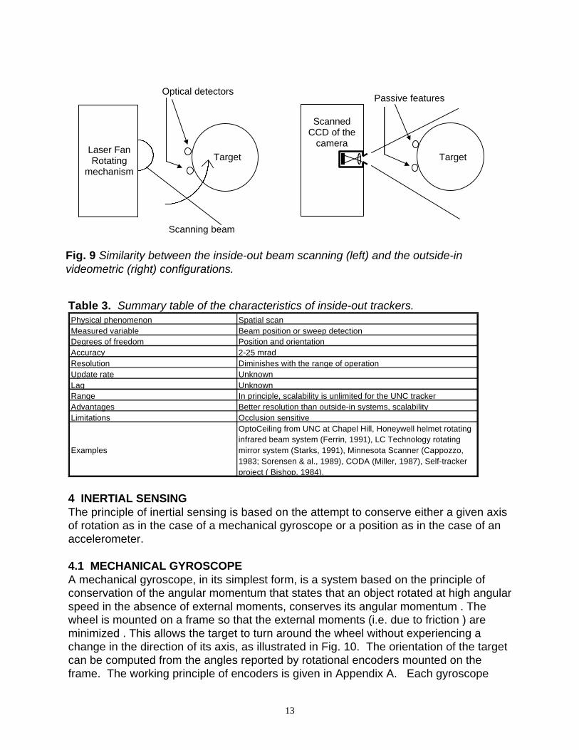
The scanning-beam technique, while an inside-out configuration, does not share theadvantage of the videometric system that provides a higher accuracy and resolution inorientation of a target. Given that the receivers are on the target, which makes it aninside-out configuration, the scanning of the working volume is done from thereference. Paradoxically, we show in Fig. 9 that such a configuration can be likened toan outside-in configuration where a camera is attached to the reference and scans thescene.
a
b
c d
Front view Side view
Fig. 8 Inside-out configuration: Structure of a beam scanning tracking system used forthe determination of pilots’ head-orientation in airplane cockpits (Honeywell).
Flat beam ray
13
Table 3. Summary table of the characteristics of inside-out trackers.Physical phenomenon Spatial scanMeasured variable Beam position or sweep detectionDegrees of freedom Position and orientationAccuracy 2-25 mradResolution Diminishes with the range of operationUpdate rate UnknownLag UnknownRange In principle, scalability is unlimited for the UNC trackerAdvantages Better resolution than outside-in systems, scalabilityLimitations Occlusion sensitive
Examples
OptoCeiling from UNC at Chapel Hill, Honeywell helmet rotating infrared beam system (Ferrin, 1991), LC Technology rotating mirror system (Starks, 1991), Minnesota Scanner (Cappozzo, 1983; Sorensen & al., 1989), CODA (Miller, 1987), Self-tracker project ( Bishop, 1984).
4 INERTIAL SENSINGThe principle of inertial sensing is based on the attempt to conserve either a given axisof rotation as in the case of a mechanical gyroscope or a position as in the case of anaccelerometer.
4.1 MECHANICAL GYROSCOPEA mechanical gyroscope, in its simplest form, is a system based on the principle ofconservation of the angular momentum that states that an object rotated at high angularspeed in the absence of external moments, conserves its angular momentum . Thewheel is mounted on a frame so that the external moments (i.e. due to friction ) areminimized . This allows the target to turn around the wheel without experiencing achange in the direction of its axis, as illustrated in Fig. 10. The orientation of the targetcan be computed from the angles reported by rotational encoders mounted on theframe. The working principle of encoders is given in Appendix A. Each gyroscope
Scanning beam
Optical detectors
TargetLaser FanRotating
mechanism
ScannedCCD of the
camera
Target
Passive features
Fig. 9 Similarity between the inside-out beam scanning (left) and the outside-invideometric (right) configurations.

14
gives us one reference axis in space. At least two gyroscopes are needed to find theorientation of an object in space.
A main advantage of this tracking system is that it does not require an externalreference to work. The axis of the rotating wheel is the reference. The main problemof gyroscopes, however, is that the inertial momentum of the wheel does not remainparallel to the axis of rotation because of remaining small friction between the axis ofthe wheel and the bearing. This causes a drift in the direction of the wheel axis withtime. Taking relative measurements of the orientation rather than absolutemeasurements can minimize this drift. As a consequence, the system suffers fromaccumulated numerical errors but a periodic re-calibration of the system will insure,more accuracy over time.
Table 4. Summary table of the characteristics of mechanical gyroscopes.Physical phenomenon Inertia
Measured variableOrientation between the axis of rotation of the wheel and an axis attached to the target
Degrees of freedom Orientation finder (1 to 3 DOFs)Accuracy 0.2 degree, static drift 0.01 deg/s, dynamic drift 0.25 deg/sResolution 0.032 degreeUpdate rate 50 HzLag UnknownTotal Orientation Span 132 degrees in yaw, 360 degrees in roll. Advantages No reference needed
LimitationsError increases with time since measurements are relative to previous ones leading to drift of the axis with time.
ExamplesGyrotrac2 and Gyrotrac3 from VR systems, Gyropoint from Gyration.
Fixed orientationof the wheel axis
Encoders-equipped axes
Target
Fig. 10 Structure of a mechanical gyroscope.
Motor
Inertial wheel
X
Y
Z

15
4.2 ACCELEROMETERAn accelerometer measures the linear acceleration of an object to which it is attached.An accelerometer can be specified as a single-degree-of-freedom device, which hassome kind of mass, a spring like supporting system, and a frame structure with dampingproperties. It may rely for example on a mass mounted on a piezo-electric crystal andattached to the target as shown in Fig. 11. In this case, the motion of the targetproduces a pressure on the crystal because of the inertia of the mass. The resultingforce, proportional to the acceleration, can be evaluated by measuring the voltageappearing on the sides of the piezo-electric crystal. The double integration in time ofthe acceleration yields the position, assuming that the initial conditions of the target(position and speed) are known. This sensor is lightweight and is reference free.Accelerometers are position finders having one degree of freedom and come in manyforms including capacitive, nulling, piezo-resistive, and thermal accelerometers.
Table 5. Summary table of the characteristics of accelerometers.Physical phenomenon Mass inertiaMeasured variable Depends on implementation. Degree of freedom Position along one axis only (1 DOF)Accuracy UnknownResolution UnknownUpdate rate Depends on the processing time to integrate two timesLag Depends on the processing time to integrate two timesRange UnlimitedAdvantages No reference needed; lightLimitations Errors in position due to integrationExamples Unknown
TensionUq
Direction of acceleration
Resulting force on thecrystal from the inertia
of the mass
Mass
Targetsupport
Fig. 11. Structure of an accelerometer.

16
5 MECHANICAL LINKAGES
This type of tracking system uses mechanical linkages between the reference and thetarget (Jau, 1991). Two types of linkages have been used. One is an assembly ofmechanical parts that can each rotate providing the user with multiple rotationcapabilities, as shown in Fig. 12. The orientation of the linkages is computed from thevarious linkages angles measured with incremental encoders or potentiometers. Othertypes of mechanical linkages are wires that are rolled on coils. A spring systemensures that the wires are tensed in order to measure the distance accurately. Thedegrees of freedom sensed by mechanical linkage trackers are dependent upon theconstitution of the tracker mechanical structure. While six degrees of freedom are mostoften provided, typically only a limited range of motions is possible because of thekinematics of the joints and the length of each link. Also, the weight and thedeformation of the structure increase with the distance of the target from the referenceand impose a limit on the working volume. Mechanical linkage trackers have foundsuccessful implementations among others in force-feedback systems used to make thevirtual experience more interactive (Brooks et al., 1990; Massie, 1993).
target
Mechanical links equippedwith encodersReference
Fig. 12. Structure of a typical mechanically linked tracking system.

17
Table 6. Summary table of the characteristics of mechanical linkages trackersPhysical phenomenon Mechanical linkagesMeasured variable Angle measured by rotating encoder(s)Degrees of freedom Position and orientation (Up to 6 DOFs)Accuracy 0.1-2.5 mmResolution 0.05-1.5 mm / 0.15-1 degreeUpdate rate Depends on data aqusition capabilities. (about 300 Hz)Lag 3 ms
Range / Total Orientation Span1.8m / 40 degrees ; Limited by the weight and deformation of the mechanical structure with distance from reference.
AdvantagesGood accuracy, precision, update rate, and lag. No environmental linked error.
Limitations Encoder resolution, limitation of motion.
Examples
FaroArm(1), Phantom(1), Spidar(2), Anthropomorphic Remote Manipulator from NASA (Jau, 1991), Argonne Remote Manipulator (ARM), Fake Space Binocular Omni-Oriented Monitor (BOOM), GE Handyman Manipulator, MITI position tracker, Noll Box, RediffusionADL-1 (Shooting Star Technology), Wrightrac(Magellan Marketing), PROBE-IC and PROBE-IX (Immersion Human Interface), Sutherland Head Mounted Display project, University of Tsukuba Master Manipulator. Spidar II (wire tracker) (Hirata and Sato, 1995)
6 PHASE-DIFFERENCEPhase-difference systems measure the relative phase of an incoming signal from atarget and a comparison signal of the same frequency located on the reference. As inthe TOF approach, the system is equipped with three emitters on the target and threereceivers on the reference, as shown in Fig. 13. Ivan Sutherland's head trackingsystem, built at the dawn of time when it comes to virtual reality, explored the use of anultrasonic phase-difference head tracking system and reported preliminary results(Sutherland, 1968). In Sutherland’s system, each emitter sent a continuous soundwave at a specific frequency. All the receivers detected the signal simultaneously. Foreach receiver, the signal phase was compared to that of the reference signal. Adisplacement of the target from one measure to another produced a modification of thephases that indicated the relative motion of the emitters with respect to the receivers.After three emitters had been localized, the orientation and position of the target couldbe calculated. It is important to note that the maximum motion possible between twomeasurements is limited by the wavelength of the signal. Current systems use solelyultrasonic waves that typically limit the relative range of motion between twomeasurements to 8 mm. Future systems may include phase-difference measurementsof optical waves as a natural extension of the principle that may find best application inhybrid systems. Because it is not possible to measure the phase of light wavesdirectly, interferometric techniques can be employed to this end. The relative range ofmotion between two measurements will be limited to be less than the wavelength oflight unless the ambiguity is eliminated using hybrid technology.

18
The main disadvantage of phase-difference ultrasonic trackers is their vulnerability tocumulative errors in the measurement process. Other limitations are their sensitivitiesto environmental conditions (e.g. sensitivity to temperature, pressure, humidity, andultrasonic noise), and multiple reflections in the environment. Finally, trackers basedon phase-difference measurements are limited to relative motion measurements. Theywill need to be associated with another measuring scheme if absolute measurementsare necessary. Such a scheme will also limit cumulative errors obtained from solerelative measures.
A main advantage of phase-difference trackers is their ability to generate high datarates because the phase can be measured continuously. It is then possible to usefiltering to overcome environmental perturbations. As a result, accuracy and resolutionare improved compared TOF ultrasonic trackers.
Table 7. Summary table of the characteristics of phase-differencetrackers.Physical phenomenon Phase difference sensing (e.g. ultrasonic, optical)Measured variable Phase differenceDegrees of freedom Orientation and position (6 DOFs)Accuracy UnknownResolution 0.1mm, 0.1 degree, 1/32 of the maximum rangeUpdate rate Independent of the range of operationLag Independent of the range of operationRange UnknownAdvantages Less sensitive to noise than TOF systems, high data rate
LimitationsError increases in time since relative measurements. Sensitive to occlusion. Possible ambiguity in reported measures
ExamplesSutherland-Seitz-Pezaris head mounted display position tracker (Sutherland, 1968).
Target
Reference
Phase difference indicative ofthe relative motion
Upcoming target signalReference signal
Fig. 13. Working principle of phase coherent tracking system.

19
7 DIRECT-FIELD SENSING7.1 MAGNETIC FIELD SENSINGBy circulating an electric current in acoil, a magnetic field is generated inthe coil (Potter, 1967). The field atsome distance r has the followingpolar components Br (along the radialdirection) and Bθ (perpendicular tothe radial direction) represented inFig. 14. If a receiver (some magneticfield sensor) is placed in the vicinity,the field induces a flux in thereceiver. This is referred to asmagnetic coupling between theemitting coil and the receiver. Thesensor output resulting from the induced flux can then be measured (Souders, 1966).The flux in the vicinity of the receiver is a function of the distance of the receiver fromthe coil and of its orientation relative to the coil.
To measure position and orientation of a receiver in space, the emitter must becomposed of three coils placed perpendicular to each other, thus defining a spatialreferential from which a magnetic field can exit in any direction. The direction is givenby the resultant of three elementary orthogonal directions. On the receiver, threesensors measure the components of the field’s flux received as a consequence ofmagnetic coupling. Based on these measures, the system determines the position andorientation of the receiver with respect to the emitter attached to the reference (Raab,1977; Raab, 1979). It is typically required that r>>R and r>>L, where r is the distanceof the receiver from the coil, and R and L are the radius and the length of the coil,respectively as shown in Fig. 14.
As stated, the position and the orientation of a receiver could be achieved simply byemitting a field along each coil of the emitting unity, but it is found with this approach,that it is difficult to solve for the position and the orientation. A practical solutionactually involves the emission of three orthogonal fields: one in the estimated directionof the target and two others in the orthogonal directions (Raab, 1979).
Because magnetic trackers are inexpensive, light weight, and compact, they are widelyused in virtual environments. The working volume is limited by the attenuation of thesignal with the distance. However, the field cannot be increased indefinitely in order toimprove the working volume because the effects of significant electromagnetic fields onhumans are not completely discovered. The update rate may be limited if filtering isapplied to smooth the received signals. A trade-off must be made between the workingvolume, the accuracy and resolution, and the update rate.
X
Y
Z
Coil
θr
Br
Bθ
B
Fig. 14 Radiating electromagnetic fieldcomponents.

20
7.1.1 SINUSOIDAL ALTERNATING CURRENT (AC)This type of magnetic tracker is based on alternating the current feeding the emittingcoils. This produces a changing magnetic field (Polhemus, 1972). The current inducedby the changing field in each of three receiving coils is proportional to the product ofthe amplitude of the magnetic flux and the frequency of the field oscillations. Aproblem with this system is the generation of Eddy currents in the vicinity of metallicobjects that create an opposite field distorting the emitted magnetic field (Bryson, 1992)and possibly leading to tracking errors. The variation in amplitude of the signal is whatproduces Eddy currents by induction in metal sheets (Souders, 1966). However, if themetallic objects are static, a lookup table can be in principle pre-computed to accountfor the distortions.
Table 8. Summary table of the characteristics of alternating current magnetic trackers.
Physical phenomenonMagnetic coupling of two coils one of which is fed with sinusoidal alternating current
Measured variable Amplitude at the output of the receiving coilDegrees of freedom Orientation and position (6 DOFs)Accuracy 0.8 mm to 25 mm (75mm at 5m) / 0.15 to 3 degreesResolution 0.04 mm to 0.8 / 0.025 to 0.1 degreeUpdate rate 15-120 Hz divided by the number of emittersLag 4-20 msRange / Total Orientation Span up to 5000 mm / 360 degrees
AdvantagesNo occlusion problem, high update rate, low lag, inexpensive, small.
LimitationsSmall working volume, distortion of accuracy with distance, sensitive to electromagnetic noise in the 8-1000Hz range and metallic objects
Examples Fastrack, Isotrack, Insidetrack and Ultratrack from Polhemus (Polhemus, 1972), Honeywell, Rediffusion Zeis, Ferranti, Israeli government.
7.1.2 PULSED DIRECT CURRENT (DC)In contrast to the previously described system, this system uses a pulsed constantcurrent to excite the sensors. The receiver is composed of sensors capable ofdetecting a constant magnetic flux such as magnetrons (Ascension, 1991). During theraising front of the pulse, Eddy currents are generated as in the AC systems. However,a DC system would wait until these currents die out to take a measurement so that thedistortions by Eddy currents would be eliminated. Actually one would have to wait aninfinitely long time for Eddy currents to fully vanish therefore the DC systems wait thelongest possible time determined by the acquisition rate of tracking before making ameasurement. For instance, to make one measurement of magnetic flux per second,the DC system produces the following sequence: at t equal 0 a DC magnetic field isinduced. Next, the system waits 999 ms, the longest time allowed by the acquisitionrate. Finally at t equal 1 sec. the DC system measures the magnetic field. The pulsedDC method reduces significantly the influence of Eddy currents on the accuracy ofmeasurements. A problem with this type of trackers is the distortion of the magneticfield by Ferro-magnetic objects and other sources of electromagnetic fields such ascomputer monitors. A calibration procedure at startup of the system should measure

21
the magnetic field bias produced by both the Earth's electromagnetic field and othersources to optimize the system performance.
Table 9. Summary table of the characteristics of pulsed direct current magnetictrackers.Physical phenomenon Magnetic couplingMeasured variable Amplitude in output of the receiving sensorDegrees of freedom Orientation and position (6 DOFs)Accuracy 2.5 mm / 0.1-0.5 degreeResolution 0.8 mm / 0.1 degreeUpdate rate 144 HzLag 22 msRange 600-2400 mm radius of radiating magnetic sphere
AdvantagesNo occlusion problem, small, high update rate, low lag, inexpensive
LimitationsSmall working volume, accuracy degraded with distance, sensitive to electromagnetic noise in the 8-1000Hz range and ferromagnetic objects
ExamplesAscension Bird, Big Bird and Flock of Birds (Ascension, 1972 & 1991).
7.1.3 MAGNETOMETER / COMPASMagnetometers measure the orientation of an object with respect to the magnetic fieldof the earth. Magnetic field sensors include fluxgate, Hall effect, magneto-resistive,and magneto-inductive sensors (Fraden, 1997). The most relevant magnetometers usemagneto-inductive sensors. Such sensors operate, for example, on the change ininductance of a coil in the presence of an external magnetic field component parallel tothe axis of coil. If the coil is used in a L/R oscillator, the output frequency of theoscillator changes. The change in frequency allows determination of the strength ofthe magnetic field. With three sensors, the orientation of an object with respect to themagnetic field can be determined. The other angular degrees of freedom are measuredby other means for instance by inclinometers. One problem with this technology is thatthe Earth's electromagnetic field is inhomogeneous and yields angular errors in theorientation measurements. As noted in previous methods, relative measurements canbe implemented to compensate for these errors. This technique works well if betweentwo measurements the field is quasi-constant. Naturally, such technology is sensitiveto disturbances in the ambient magnetic field. Precision Navigation uses compass forexample in their product TCMVR50.

22
Table 10. Summary table of the characteristics of magnetometers.Physical phenomenon Magnetic field sensingMeasured variable Depends on implementationDegrees of freedom Position following one direction (1 DOF)Accuracy 1-3 degreesResolution UnknownUpdate rate UnknownLag UnknownRange UnknownAdvantages No reference neededLimitations UnknownExamples Component of Precision Navigation (TCMVR50)
7.2 GRAVITATIONAL FIELD SENSINGAn inclinometer operates on the principle of a pendulum. Common implementationsuse electrolytic or capacitive sensing of fluids. A simple implementation may measurethe relative level of fluids in two branches of a tube to compute inclination. A commonimplementation measures the capacitance of a component being changed based on thelevel of fluid in the capacitor. Another, perhaps less common implementation is that ofan optical inclinometer shown in Fig. 15. A viscous and opaque liquid is placedbetween two optical vertical panels (Fuchs, 1996). One of the panels produces uniformlight that is received by the other panel on a linear array of photosensitive detectors.The viscous liquid surface keeps its perpendicular orientation with respect to theearth's gravitational field, and a number of photosensitive detectors are lighted whileothers are prevented from receiving light because of the opacity of the liquid. Thisnumber indicates the orientation of the liquid, therefore of the gravitational field withrespect to the target, making it a one-degree-of-freedom orientation finder. Wepostulate that the problem with this sensor is the slow reaction time imposed by theviscosity of the liquid. The vibration and acceleration of the sensor also will affect themeasurements.
Excitedreceivers
Non excitedreceivers
Viscous andopaque liquid
Givenorientation to
the target
Fig. 15. Principle of operation and structure of an optical inclinometer.

23
Table 11. Summary table of the characteristics of inclinometers.Physical phenomenon Gravitational field sensingMeasured variable relative heights; capacitance Degrees of freedom Orientation following one direction (1 DOF)Accuracy Repeatability of 0.5 degreeResolution UnknownUpdate rate UnknownLag UnknownTotal Orientation Span 150 degreesAdvantages No reference neededLimitations Reaction time degraded by viscosity of liquidExamples EX-TILT 2000 from AOSI
8 HYBRID SYSTEMSHybrid technology refers to the combination of various technologies (e.g. optical andmechanical). We would like to extend that definition to include also systems based ondifferent principles of operation such as time of flight measurements versus phasedifference measurements. While hybrid technologies increase the complexity of atracking system and likely its cost, they are adopted either to access variables that onetechnology cannot easily provide (relative and absolute measurements), or to makeexhaustive measurements. In the latter case, when associated with filtering andpredictive techniques, sensor fusion techniques are used to associate incomplete datasets coming from different sensor types. Five examples of hybrid systems arepresented to illustrate how hybrid systems may be built: inertial, inside-out/inertial,magnetic/videometric, and two TOF/mechanical linkages/videometric systems. It isbeyond the scope of this paper to present a comprehensive review of all hybridsystems that have possibly been conceived.
8.1 HYBRID INERTIAL PLATFORMSWe shall present two hybrid inertial platforms. The first platform is composed of threeaccelerometers and three gyroscopes mounted on a target. The accelerometersmeasure the acceleration of the target along three independent perpendicular axes andthe gyroscopes measure the orientation of the target along the same axes. Gyrometerscould be used instead of gyroscopes to access the angular velocity rather than theorientation. By integration of angular velocity, orientation can be estimated. Similarly,the double integration of the measured accelerations leads to the spatial position. Themain limitation of gyroscopes is drift. The main limitation of accelerometers is theintegration process that leads to additional errors.
The second platform relies on three accelerometers and two inclinometers and amagnetometer. As seen earlier, a magnetometer can determine the physical Northdirection, thus measuring the orientation of a target along the Y-axis (Yaw).Inclinometers placed on the X- and Z-axes can provide the orientation of a target alongthese axes as well. These platforms without sources on a reference constitute sixdegrees of freedom self-trackers that are compact and light weight (Foxlin, 1996).

24
Table 12. Summary table of the hybrid inertial platforms characteristicsPhysical phenomenon Direct field sensing and inertiaMeasured variables Depends on implementationDegrees of freedom Orientation and position finder (6 degrees of freedom)Accuracy UnknownResolution 10 ug in acceleration, 0.002 degree in rotationUpdate rate UnknownLag UnknownRange Up to 10 g for acceleration, 500 deg/s in rotationAdvantages Compact and no reference needed.Limitations UnknownExamples Motion Pack from Systron-Donner
8.2 INSIDE-OUT / INERTIALAzuma proposed such a system as part of his doctoral thesis to improve the inside-outoptical tracking system at UNC (Azuma, 1995). The improvement relied on usingKalman filtering to predict head motion. The filter inputs were the outputs of an inertialplatform added to the head-mounted display. A standard Kalman filter was used for theprediction of head position while an Extended Kalman Filter was used for orientation tohandle the non linearity of the quaternions used to represent orientation. The inertialsensor included three angular rate gyroscopes (i.e. gyrometers) and three linearaccelerometers. The three gyrometers performed measures of a user's head angularvelocities around three orthogonal axes. The linear accelerometers conductedmeasures of the head linear acceleration along the same axes. Azuma reported thatthis technique helped greatly removing what is known as the swimming of virtualimages. Registration still remained a challenge. Azuma further showed improvementsin the use of this technology by a factor of 5 to 10 compared to techniques using noprediction tracking and by a factor of 2 to 3 compared to techniques with no inertialsensors. This platform allowed the resolution of small fast movements in a shorter timethan the original configuration would have allowed.

25
Table 13. Summary table of advantages and disadvantages of Inside-out /Inertial hybrid systems.
Inside-out Inertial Hybrid
Characteristics /Advantages
Measures orientationand position,
accurate.
Compact, noocclusion problemsgive stable solutionfor orientation andposition predictionsand small lag whenoutput filtered byKalman predictor.
Compact, accurate,Small lag, stable.
Limitations Unstable, resolutionmay degrade with
distance(implementation
dependent),occlusions sensitive,
processing lag.
Long term drift of theorientation.
Occlusion sensitive.
8.3 MAGNETIC / VIDEOMETRICThis system, developed by State, was composed of a magnetic and an inside-outvideometric tracker (State, 1996). The cameras of the videometric tracker as well asthe receivers of the magnetic tracker were placed on the target (see Fig. 5). Thesystem was used to measure the position and orientation of the head of a user in avirtual environment with respect to stationary objects in that environment. As aconsequence we refer to the head of the user as the target, and the objects in the worldas the references. The inside-out videometric system detected dual color-codedlandmarks placed on the objects. Two cameras placed on the target were usedbecause the detection of at least three landmarks was necessary to recover theposition and orientation of the target.
The magnetic tracking system was used to detect the gross positions and orientationsof a target and determine the field of view within which the image processing was to beperformed. A global non-linear equation solver and a local least-square minimizerwere used to determine the effective field of view. The calibration of the magnetictracker was performed during a setup procedure according to the parameters given bythe videometric system. The magnetic tracker was also used to remove any possibleambiguity in the occurrence of multiple solutions. Finally, it was used to verify that thesolution provided by the videometric system was reasonable given instabilities thatmight have occurred. The system had the robustness of a magnetic tracker and theaccuracy of a videometric tracker (State, 1996).

26
Table 14. Summary table of the characteristics of videometric / magnetic trackingsystem.Physical phenomenon Spatial scan and direct field sensingMeasured variables Image analysis and electromagnetic fluxDegrees of freedom Position and orientation (6 DOFs)Accuracy UnknownResolution UnknownUpdate rate UnknownLag Unknown
RangeDepends on the visibility of the landmarks and the distance from the receiver for the magnetic part
Advantages Fast, accurate and robustLimitations Same as optical and magnetic systemExamples State system at UNC-CH (State, 1996)
Table 15. Summary table of the advantages and disadvantages of magnetic /videometric hybrid systems.
Pulse direct current(Magnetic)
Videometric Hybrid
Characteristics /Advantages
Robust, no occlusionsensitivity,
inexpensive, fast,measure orientation
and position.
Accurate, insensitiveto electromagnetic
noise andferromagnetic object,measures orientation
and position.
Accurate, robust,insensitive to
environment andocclusions, measure
position andorientation.
Limitations Non accurate,sensitive to
electromagnetic noiseand ferromagnetic
objects.
Unstable, sensitive toocclusions, lag due to
processing.
Lag due toprocessing of
videometric data.
8.4 TOF / MECHANICAL LINKAGES / VIDEOMETRIC POSITION TRACKERThis hybrid system developed by Maykynen et al. (1992) included a pointing deviceand a range finder. The pointing device was based on optical technology and wascomposed of an infrared emitter and a 4Q (four quadra) detector. The infrared lightwas reflected off a feature on a target to be localized. The 4Q detector actuated a two-axis motorized gimbal that kept the feature being localized at the center of the sensor.The use of a 4Q detector allowed direct control of the motors of the gimbals by usingthe voltage available at the detector output. The optical axis of the pointing device wascoaxial to the beam axis of the rangefinder. The rangefinder method of measurementwas based on the principle of time-of-flight of infrared waves. Once the target wasaimed, the range-finder measured the distance from the reference to the target bysending an infrared beam to the target equipped of a reflective mirror (e.g. sign paintand cat's eye reflector). Illustration of the principle is shown in Fig. 16. Incrementalencoders attached to the axis of the pointing device determined elevation and azimuth.The TOF device determined the distance of the target thus yielding, with the elevationand azimuth measures, the position in space of the target as shown in Fig. 17.

27
The accuracy and resolution of the system relied on the qualities of the motorized partsof the gimbals as well as on the electronics of the TOF-distance conversion. Becausethe speed of the measuring process was high, numerous measurements could beaveraged in order to improve the accuracy of a measure. The ability to only track onefeature at a time limits the system. The system has been mostly used for themeasurement of large structures in outdoor environments, however we see nofundamental limitation that would prohibit its use for applications perhaps on a smallerscale. High-speed electronics is needed in this case because light passes 30 cm in1ns, so time of flight measurements must provide nano-scale resolution or higherdepending on the accuracy and resolution requirements.
Object 3Dfeature
Motion on azimuth
4Qdetector
IRED
Laser range finder
Elevation
Azimuth
Motion onelevation
Fig. 16. Structure of a TOF / mechanicallinkages / videometric tracking system.
Camera image
X
Y
Z
elevation
azimuth
distance
Target
Fig. 17. Geometrical view of the measurement method of a TOF / mchanical linkages /videometric tracking system.

28
Table 16. Summary table of the characteristics of TOF / mechanical linkages /videometric system.Physical phenomenon TOF, mechanical linkages, videometricMeasured variables Time of flight, 2D projection feature, anglesDegrees of freedom 3 DOFs (position in space)Accuracy Depends on applicationResolution Depends on applicationUpdate rate UnknownLag UnknownRange UnknownAdvantages Long distance measurement
LimitationsNeed a reflective surface on the target. Can track one feature at a time
Examples Large workship measurement apparatus (Makynen, 1994)
Table 17. Summary table of the advantages and disadvantages of TOF /Videometric hybrid systems.
Videometric /Mechanical Linkages
pointing
TOF infraredreflective rangemeasurement
Hybrid
Characteristics /Advantages
Pointing accurate, by4Q detector, line ofsight measurement,determine azimuth
and elevation.
Fast rangemeasurement, which
allows accuracythrough averaging,
long range, andwireless.
Positionmeasurements, fast,accurate, long range,
and wireless.
Limitations Mechanical gimbalconditions accuracy
and precision ofazimuth and elevation
determination.
Expensive rangemeasurement
detector can only beused for a target at a
time.
Expensive, trackonly one target at a
time.

29
8.5 TOF / MECHANICAL LINKAGES/ VIDEOMETRIC 5-DOFS TRACKER
The orientation of an object can be determined by tracking the position of at least threefeatures with three locating systems such as those introduced in the previous section.
IREDA
IRED B
IREDC
Elevation EpAzimuth Ap
Elevation Ac
Azimuth Ap
A
B
C
Length alsoindicative of the
elevation Ep
D1
D2
D
D=D1+D2 2
Elevation Ep and Ddetermined by D1 and D2
TOF determination
Figure 18. Structure of a TOF / Mechanical Linkages / Videometrictracking system.

30
This TOF/ mechanical linkages / videometric 5 DOFs tracker uses an original methodto perform this function with a unique device. The tracking system is composed of aTOF infrared rangefinder and a pointing device similar to the previous system. Thesystem is illustrated in Fig. 18. This tracking system was originally proposed to teachrobot paths (Mäkynen, 1995).
The target, a pen in this example, is equipped with three LEDs firing in the infrared.The pointing device aims constantly at the center of the diode, providing its elevationand azimuth to the processing unit via encoders mounted on the axis of the holdinggimbal. The processing unit triggers the bottom and top tips of the pen where twoLEDs are located. The TOFs of the two beams are measured by the rangefinder. Theaveraging of the two TOFs yields the distance of the central LED. As a result, theposition of the center of the pen can be computed by the use of the elevation andazimuth variables.
Orientation in pitch of the pen is determined from the times of arrival of the infraredpulses. If the pen is vertical, the times of arrival are the same. If the pen is tilted awayfrom the vertical, one pulse is delayed with respect to the other, and the delay is afunction of the amplitude of the pitch. The actual working of the system involves asequential firing of the two diodes with a delay Td between each firing. Such a delay isnecessary in practice to distinguish between the two signals emitted. One of the signalsis therefore delayed by a time Td after reception for comparison. The pointing deviceequipped with a CCD sensing array instead of a 4Q detector as previously adoptedmeasures the orientation in roll. The detection of the positions of the two extremediodes at the time they fire leads to the identification of the roll of the pen. These twoorientations and the position of the central point of the pen yield a 5 DOFs trackingsystem.
Table 18. Summary table with characteristic of TOF / mechanical linkages /videometric tracking system.Physical phenomenon TOF, mechanical linkages, and spatial scanMeasured variable TOF, 2D position and gimbal encoders outputsDegrees of freedom 2 Orientation and position (5 DOFs)Accuracy 1 mm for range-finder, 5 mm for the whole systemResolution 1.3 mm / 0.3 degUpdate rate UnknownLag UnknownRange / Total Orientation Span Up to 5m / 80 degrees ( field of operation of the gimbals)Advantages UnknownLimitations UnknownExamples Laser radar to teach robot paths (Makynen, 1995)

31
Table 19. Summary table of the advantages and disadvantages of TOF /Mechanical Linkages / Videometric 5DOFs hybrid systems.
Videometric /Mechanical Linkages
pointing
TOF infrared rangefinding and orientation
determination
Hybrid
Characteristics /Advantages
Measures azimuthand elevation.
Determine orientationby TOF difference,fast, long range and
accurate.
2 Orientations and 3position measures,fast, accurate, long
range.Limitations Videometric system
and gimbalmechanics limit the
accuracy andresolution in position.
Need wires to bringback to the controlunit the received
signals, expensivetime detector.
Expensive, controlwires needed,accuracy and
resolution in positionlimited by mechanicsof the gimbal and the
quality of thevideometric system.
9 DISCUSSIONAfter reviewing some unique advantages and disadvantages of various trackingtechnologies, whether in isolation or in hybrid configurations, we shall now discusscommon issues to these technologies. First we shall ask and discuss whether thereare fundamental limitations in aiming for finer and finer accuracy and resolution. Nextwe shall discuss a critical technical challenge for virtual environments, the capability forreal-time operation. We shall then address the issue of scalability of the technologythat is especially relevant to large virtual environments where users are physicallynavigating through the virtual world (e.g. larger indoors or outdoors settings). Finally,general considerations for the choice of tracking technologies are discussed.
A review of tracking devices according to their fundamental principle of operation mayexamine the theoretical limitations in accuracy and resolution (i.e. resolution) of thesesystems. Because of the way accuracy is defined, it is a measure of the absoluteerror of either position or orientation of an object in the tracker coordinate system. Achange in coordinate system yields values of these measures in the world coordinatesystem. Accuracy in either position or orientation refers to an estimation of the positionor orientation of an object after the system noise has been fully accounted for and in away averaged. A measure of accuracy, therefore, assumes that a large number ofsamples have been collected for a given position and orientation of an object in orderto yield unbiased estimates of the mean values of the underlying distributions inposition and orientations. In this regard the fundamental limitation of obtaining perfectaccuracy in position and orientation is the Heisenberg uncertainty relation. In ourmacroscopic world this limitation is negligible but for instance STM microscopy can alsobe considered as a tracking technology and the uncertainty relations are playing amajor role in this case. Other limitations to perfect accuracy are thermal noise in theelectronic circuits and quantum noise in the sensors. Cooling the circuits and detectorscan minimize noise.

32
A measure of resolution, in the other hand, quantifies the noise of the tracking system.Resolution is a measure of the spread of an underlying distribution in either position ororientation. Resolution can thus be defined as the square root of the second centralmoment of the considered distribution (Frieden, 1982). All trackers are theoreticallylimited in resolution by a quantification unit (e.g. the size of a quantum of light in someoptical trackers). At the working scale of the technology, where the application is thetracking of human scale features (e.g. the head), the resolution sought by the trackingtechnology considered is a lot larger than the quantification units considered (e.g.wavelength, phase, molecules size).
An exception, perhaps, is the case where secondary parameters are measured withtechnologies that supersede microscale technology. An example is the measurementof head acceleration with nanoscale technology developed by NASA (Tom Caudell,1998). It has been shown that nanoscale accelerometers are limited in resolution dueto interference of gravitational fields that may constitute a fundamental limitation insuch measurements. As finer scale technologies are developed and investigated evenbeyond nanoscale technologies, other fundamental limitations are likely to bediscovered. While such resolution requirements are likely beyond most applications, itis important to understand such phenomena and be able to set lower bounds on whatcan be achieved and what cannot. Nanoscale technology, for example, is now at thecutting edge but may be part of tomorrow every day’s technology.
In today’s' reality, two common practical limitations in resolution are brought from thestate-of-the-art electronics and the manufacturing of various components of thetrackers. Electronics is an essential component in the emission, detection, andprocessing of the measured variables (e.g. time of flight). The finite speed of theelectronic signals produces a lag in the measurements. The limited bandwidth of thesesignals also limits the data acquisition rates. As an example, one may increase theoperating frequency used in a phase coherent system with ultrasonic waves in order toincrease the resolution. A limit in the case of ultrasonic wave, depending on theiramplitude, may be simply the viscosity of the air: the bigger the frequency the larger theattenuation. The electronic response times would however impose a limit on themaximum data acquisition rates, thus also limiting the resolution of the trackingsystem. Optical data processing devices present promises for future improvementsbecause of the larger bandwidth of the optical signals and the shorter switching times.
The manufacturing specifications of the emitting and sensing components of thetracking system often limit the resolution of current tracking technology, but not in anyfundamental way. As examples, the current resolution of a CCD array, or thearchitectural layout and the geometry of emitting and sensing sources, limit theresolution. Achievable resolutions rely essentially on the progress of technologiesincluding micro and nano scales electronics, mechanics, and opto-electronics.However, even if optical switching devices, for example, were to successfully replaceelectronic devices, and manufacturing errors were reduced to become negligible, theachievable resolution for an overall application would be limited by other components

33
or factors of the virtual reality system, other than tracking components. For example,the resolution of the display used in the visualization and the natural occurrences ofmechanical vibrations are sources of limitation as well. Finally, given the sametechnology, different implementations often lead to different final performances.There is no need to seek higher resolution for the tracking system than can bedelivered by individual components of the overall virtual reality system.
An issue of critical importance for trackers is their real-time capability. A virtual realitysystem qualifies as real-time if the virtual world reacts synchronously to the actionsproduced by a user. Because this capability is practically not reachable the preferredterm of interactive speed is commonly used. The difficulty in achieving interactive-speed results from the reception of non-synchronous signals coming from the realworld (we see the real hand moving) and the virtual world (we see the virtual handmoving on the display). The signals from the real world appear as they are produced ifseen directly (see the real hand), whereas the signals from the virtual world appearwhen the processing that produces them (time taken from end-to-end process of thevirtual environment) is completed. Moreover, virtual signals are often generatedfollowing the detection of a real signal (the detection of a hand motion), thusaggravating the problem.
The total lag produced by this process comes from the establishment of themeasurement conditions, the measurement completion time before availability of themeasure, the filtering, the signal propagation and transmission times, and thesynchronization between the tracking system, the computer, and the display. Differentimplementations may also have different temporal performances (Jacoby et al., 1996).To minimize the effect of lag, Kalman filtering (Kalman, 1960) has been used to predictthe position of a target according to the present and past speed and positionparameters (Azuma, 1995). The time of prediction can be tuned to equalize the lagproduced by the system to produce virtual signals with the impression of an interactive-speed response. However, the predicted position and orientation are sole estimationsproduced from the last measurements and do not reflect exactly a real position. As aresult, the lag problem is often replaced by noticeable registration errors.
In applications requiring registration of real and virtual objects, the lag, the update rate,and the errors in position and orientation are hindrances. Motion sickness can ensue ifthese variables are incorrect because of visual-proprioceptive conflicts (Kennedy andStanney, 1997). The severity of the observed errors is a function of other systemparameters (e.g. effectiveness of visual cues, use of sound) and the speed of variousmoving parts among others. Evaluating a tracker in the context of specific applicationsis a key requirement.
Another important issue of tracker technology development is the potential forscalability of the technology. In certain cases, it becomes the driving factor foradopting a certain approach to tracking. At the University of North Carolina at ChapelHill, for example, the opto-ceiling tracker was essentially developed using an inside-out

34
configuration because such an approach was believed to have the potential for naturalscalability indoors. Such a system was described in section 3.2.1 and illustrated in Fig.7. In this case, scalability was traded-off the need to wear three cameras on the headthat appeared highly displeasing. This problem can be and is being addressed byadopting custom-made miniature camera configurations (Welch and Bishop, 1997).The first implementation of the tracking system succeeded in demonstrating tracking ina small volume (~ 10x10 feet), and the second implementation demonstrated somescalability of the system (a factor of 2 in one dimension). Practical issues however(e.g. the requirement for precise calibration of all LED-panels and associated cost) setsome limit on scalability. Self-calibration was attempted to remedy this problem but theoptimization becomes rapidly untractable for larger and larger volumes (Gottschalk andHughes, 1993). Scalability is fairly challenging indeed for most technologies andtheoretical as well as practical considerations have to be carefully examined. Afterreflecting on the scalability issues of the various technologies described in thisdocument, we postulate that, most systems are scaleable for indoor settings if theexpense is not of primary concern and hybrid technologies can be considered. Mostsystems are not however scalable to handle large navigation settings such as may berequired for outdoors navigation. Likely, such tracking will not require the highaccuracy and precision typical of most indoor settings. Generally speaking, however,scalability may imply that more complex algorithms (e.g. fusion algorithms) will benecessary as systems are being scaled and hybrid technologies are implemented.
To conclude this discussion, we shall now summarize some general considerations oftracking technology for virtual environments. TOF ultrasonic systems typically sufferfrom ultrasonic noise sources in the environment, while other TOF systems such asoptical or GPS suffer from occlusion. In addition, current GPS systems do not yieldhigh accuracy and resolution. Phase difference systems based on ultrasonic sourcessuffer from environment noise sources while those based on light sources may offerattractive solutions for relative tracking measurements. Direct field sensing trackerssuch as magnetic trackers seem to be most employed in virtual environments becauseof their robustness and their low price, even though distortions of the magnetic fieldtypically cause large tracking errors. Spatial scan trackers give excellent accuracy andresolution, but they typically suffer from occlusion. Moreover, some of these systemsare complex to implement and thus tend to be expensive. Mechanical linkages havethe best accuracy, update rate, lag, and resolution, but they impose constraints ofmotion on certain degrees of freedom. Inertial platform and other reference-lesstrackers are especially well adapted for fast reaction time and long-range motion of theuser, but they suffer from drift and are best used in hybrid configurations. Given anapplication and thus the environment (e.g. small scale versus large scale, the potentialfor environment noise and occlusion), a sole technology or hybrid technology may beselected for optimal performance and trade-offs.

35
10 CONCLUSIONThis broad technical review considered existing trackers categorized according to theirphysical principle of operation in order to explore their similarities and differences. Webriefly discussed the physical principle of each technology, as well as the technologyadvantages and drawbacks. Such taxonomy based on physical principle of operationwas proposed to facilitate developing new and improved ways to track features of thereal world, as well as assist in the choice of a tracking system that best fit someapplication. At present, a major limitation of state-of-the-art tracking technologies is thedifficulty in achieving interactive-speed performance for complex virtual environments.The limitation is often a system limitation given that it depends on rendering speed aswell as on tracking acquisition and transfer to the rendering engine. The tracker itselfis often not the limiting factor.
ACKNOWLEDGMENTSWe are grateful to Tom Caudell from the University of New Mexico and one anonymousreviewer for their careful review of the manuscript, and their various insightfulsuggestions that have significantly contributed to improvement of this manuscript.From the university of Central Florida, we thank Jim Parsons for his help on definitionsand references, and Boris Zel'dovich for his help with the geometry of the Time of Flighttrackers. From the University of North Carolina at Chapel Hill, we thank StefanGottschalk and Gary Bishop for providing us with information on the opto-ceilingtracking system that has been developed over the last 10 years. Finally we arethankful to Warren Robinett for stimulating discussions on some aspects of this review.
REFERENCESArranz, A.V., and J.W. Flanigan (1994). "New tracking system for virtual reality based
on ultrasonics and using transputers," Actes des Journees in L'interface des mondesreels et virtuels, Montpellier, 359-368.
Ascension Technology Corporation (1991). "Flock of Birds, Vermont & productiondescription for high-speed tracking of multiples bird receivers and operation ofmultiple receiver and transmitter configurations", April.
Ascension Technology Corporation(1991). "Question and answers about the Bird familyof 6D input devices", Trade literature, Vermont.
Azuma, R. & Ward, W. (1991). "Space resection by Colinearity: Mathematics behindthe optical ceiling head-tracker", Department of Computer Sciences, University ofNorth Carolina at Chapel Hill, TR91-048.
Azuma, R. (1995). "Predictive tracking for augmented reality", Ph.D. dissertation, UNC-CS at Chapel Hill, TR-95-007.
Barret, S.F. Jerath, M.R., Rylander III, H.G. & Welch, A.J. (1994). "Digital tracking andcontrol of retinal images", Optical engineering, 33(1).
Bhatnagar, D.K. (1993). "Position trackers for Head Mounted Display systems: Asurvey", Department of Computer Sciences at the University of North Carolina atChapel Hill, March 29th.
Bishop, T.G. (1984). "Self-Tracker: A Smart Optical Sensor on Silicon", Ph.D.dissertation, UNC-CS at Chapel Hill, TR84-002.

36
Brooks, F.P., M. Ouh-Young, J.J. Batter, and P.J. Kilpatrick, (1990) "Project GROPE -haptics displays for scientific visualization," Computer Graphics 24(4), 177-185.
Bryson, S. (1992). "Measurement and calibration of static distortion of position datafrom 3D trackers", NASA RNR Technical report RNR-92-011.
Burdea, G. & Coiffet, P. (1993). Virtual Reality, Hermes editions, France.CAE Electronics (1991). “The visual display system you wear”, CAE-7-3739-BR, Trade
literature.Cappozzo, A., Leo, T., & Macellari, V. (1983). "The COSTEL kinematics monitoring
system: Performance and use in human movement measurements". Biomechanics,VIII-B.
Caudell, T. (1998). Department of Electrical and Computer Engineering. University ofNew Mexico. (personal communications).
Chan, K.C., Xie, J. & Shirinzadeh, B. (1992). "Using Neural Network for MotionAnalysis", Control'92, Perth 2-4.
Chavel, P. & Strand, P. (1984). "Range measurement using Talbot diffraction imagingof gratings", Applied Optics, 23(6), 862-870.
Chi, V.L., (1995) "Noise model and performance analysis of outward-looking opticaltrackers using lateral effect photo diodes," Technical Report TR95-012, University ofNorth Carolina at Chapel Hill.
Colla, A.M., Trogu, L., Zunino, R. & Bailey, E. (1995). "Digital Neuro-Implementation ofVisual Motion Tracking Systems", 1995, 0-7803-2739-X/95, IEEE.
Dewiee, T. (1989). “Range finding by the diffraction method”, Laser and Optics, 8(4),119-124.
Durlach, N.I., and A.S. Mavor, (1994) "Virtual Reality : Scientific and TechnicalChallenges," National Academy Press. Washington D.C.
Elliot, D. (1996), Understanding GPS: principles and applications. Edition Kaplan.Ferrin, F.J. (1991). "Survey of helmet tracking technologies", SPIE proceedings, Large
Screen Projection, Avionics and Helmet Mounted Displays, 1456, 86-94.Foxlin, E. (1996). "Inertial head tracker sensor fusion by a complementary separate
bias Kalman filter", Proceedings of the IEEE VRAIS'96, 185-194.Fraden, J. (1997). “Handbook of modern sensors: physics, designs, and applications”
Woodbury, N.Y. : American Institute of Physics. Frieden, B.R. (1983). Probability, Statistical Optics, and Data Testing. Springer-
Verlag. NY.Fuchs, P. (1996). Les interfaces de la réalité virtuelle, Interfaces-Les journees de
Montpellier, France.Gennery, D.B. (1992). "Visual tracking of known three dimensional objects",
International Journal of Computer Vision, 7(3), 243-270.Gottschalk, S., and J. Hughes (1993) “Autocalibration for virtual environments tracking
hardware,” Computer Graphics (Proc. of SIGGRAPH, 65-72.Harding, K.G. & Harris, J.S. (1983) "Projection moiré interferometer for vibration
analysis", Applied Optics, 22(6), 856-861.Hirata Y., and M Sato, (1995) "A measuring method of finger position in virtual work
space. technical report of the Precision and Intelligence Laboratory, 4259 Nagatsuta-Cho, Midori-Ku, Yokohama 227, Japan.

37
Horn, B.K.P. (1987). "Closed-form solution of absolute orientation using unitquaternions", Opt. Soc. Am., 4(4).
Jacoby, R.H., Adelstein, B.D. & Ellis, S.R. (1996). "Improved temporal response invirtual environments through system hardware and software reorganization",Proceedings of SPIE , 2653. Stereoscopic displays and Virtual Reality Systems III.
Jau, B. (1991). “Technical support Package on Anthropomorphic Remote Manipulatorfor NASA TECH BRIEF, 15(4) from JPL Invention Report ( Report No.NPO-17975/7222). Pasadena, CA: JPL Technology Utilization Office.
Kalman, R.E. (1960). "A new approach to linear filtering and prediction problems",transactions of the ASME, J.Basic Eng 82, D, 35-45.
Kennedy, R.S., and K.M. Stanney (1997). “Aftereffects in virtual environment exposure:psychometric issues”. In M.J. Smith, G. Salvendy, and R.J. Koubek (Eds.), Design ofcomputing systems: social and ergonomic considerations. 897-900.Amsterdam:Elsevier.
Logitech (1991). press kit.Mäkynen, A., J., Kostamovaara, J.T. & Myllylä, R.A. (1994). "Tracking laser radar for
3D shape measurements of large industrial objects based on the time-of-flight laserrange-finding and position-sensitive detection techniques", IEEE Transactions onInstrumentation and Measurement, 43(1), 40-49.
Mäkynen, A.J., Kostamovaara, J.T. & Myllylä, R.A. (1995). "Laser-radar-based threedimensional sensor for teaching robot paths", Optical engineering, 34(9).
Massie, T.H. (1993), "Design of a 3 degree of freedom force reflecting haptic interface,"SB Thesis, Department of EE and CS at MIT.
Meyer, K., Applewhite, H.L. & Biocca, F.A. (1992). "A survey of position trackers",Presence, 1(2), 173-200, MIT Press.
Meyer-Arendt, J.R. (1995). Introduction to Classical and Modern Optics, Prentice Hall,Englewood Cliffs, New Jersey 07632.
Miller, J.A.A. (1987). "Motion analysis using the twelve markers CODA-3 measurementsystem". Proceedings of the 1987 Applied Mechanics, Bioengineering and fluidsengineering conference, Cincinnati, Ohio, 343-344. ASME'87.
Noe, P., and K. Zabaneh (1994). "Relative GPS". IEEE Position Location andNavigation Symposium, 586-590.
Okereke, O.C. & Ipson, S.S. (1995). "The design and implementation of hardwired 3Dvideo position-tracking transducer", IEEE Transactions on Instrumentation andMeasurements, 44(5).
Polhemus Navigation Science Division (1972). "Operation and maintenance for the 3Dspace head tracker", OPM1056-006, 3-1 to 3-15.
Potter, J.H. (1967). Handbook of the Engineering Sciences. D. Van NOSTRANDCOMPANY, INC.
Raab, F. (1977). “Remote object position locator”, US Patent 4054881, October 1977.Raab, F., Bood, E., Steiner, O. & Jones, H. (1979). “Magnetic position and orientation
tracking system”. IEEE Transactions on Aerospace and Electronics Systems, AES-15(5), 709-717.
Rehg, J.M. & Kanade, T. (1994). "Visual tracking of self-occluding articulated objects",CMU Technical report CMU-CS-94-224.

38
Roberts, L. (1966). “The Lincoln Wand”, AFIPS Conference Proceedings, November1966 Fall, Joint Computer Conference, 29, 223-227.
Rodgers, A.G. (1991). “Advances in head tracker technology- A key contributor tohelmet vision system performance and implementation”, Society for InformationDisplay International Symposium, Digest of Technical Papers, May 6-10, 22,127-130.
Simon, D.A., Hebert, M. & Kanade T. (1993). "Real-time 3D pose estimation using ahigh-speed range sensor", CMU Technical report CMU-RI-TR-93-24.
Sorensen, B.R., Donath, M., Yang, G.B., & Starr, R.C. (1989). "The Minnesota scanner:A prototype sensor for three dimensional tracking of moving body segments". IEEETransactions on Robotics and Automation, 5(4).
Souders, Mott. (1966). "The engineer's companion, a concise handbook of engineeringfundamentals", Piedmont, California.
State, A., Hirota, G., Chen D.T., Garrett, W.F. & Livingston, M.A. (1996). "SuperiorAugmented Reality Registration by Integrating Landmark Tracking and MagneticTracking. "Proceedings of SIGGRAPH '96. In Computer Graphics Proceedings,Annual Conference Series, ACM SIGGRAPH, 429-438.
Sutherland (1968)," A head-mounted three-dimensional display, 1968 Fall JointComputer Conference, AFIPS Conference Proceedings, 33, 757-764.
Wang, J, F. (1990). "A Real-time Optical 6D Tracker for Head-mounted DisplaySystems", UNC-CS at Chapel Hill, Ph.D. dissertation, TR90-011.
Wang, J.F., Azuma, R., Bishop, G., Chi, V., Eyles, J. & Fuchs, H. (1990). "Tracking aHead-mounted Display in a Room-sized environment with Head-mounted Cameras",Proceedings of SPIE 1990 Technical Symposium on Optical Engineering andPhotonics in Aerospace Sensing, Orlando, Florida.
Welch, G., and G. Bishop (1997). “SCAAT: Incremental tracking with incompleteinformation,” Proc. of ACM SIGGRAPH.

39
APPENDIX A: DEFINITIONS
Accuracy : Error between a real and a measured position X* for each spatialposition. The extreme value of the error will be given for eachsystem. This number is evaluated by taking numerous measures at agiven location and orientation, and comparing the computed mean tothe real value. A system with an accuracy A will report a positionwithin ±A of the actual position.
Lag : Delay between the measurement of a position and orientation by atracking apparatus and the report to a device (e.g. scene generator,force feedback apparatus) requiring the orientation and positionvalues.
Real-time : Attribute of a virtual reality system in which the virtual world reactssynchronously to the actions of a user. This capability is practicallynot reachable since the processing time is not zero, so the preferredterm of interactive speed is used.
Interactive Speed: Attribute of a virtual reality system that reacts "in time" according toactions taken by an user. Such a system must be fast enough toallow a user to perform a task at hand satisfactorily.
Reference : Part of a tracking system considered fixed with respect to the motionof a target.
Resolution : Smallest resolvable change in position and orientation. A measure ofresolution is the standard deviation of the underlying distribution ofmeasurements around the mean of a measured position ororientation.
User : Person interacting in a virtual world. Can be a target.
Target : Feature (e.g. object, landmark, human feature) to be localized by thetracking process.
Update rate : Maximum frequency of report of position or orientation.
Pitch : Rotation in the vertical plane including the line of sight around the Xaxis shown in Fig. A1. Pitch is called also heading.
Yaw : Rotation in the horizontal plane including the line of sight around theY axis shown in Fig. A1.

40
Roll : Rotation in the plane perpendicular to the line of sight around the Zaxis shown in Fig. A1.
Degree-of-freedom : Capability of motion in translation or rotation. There are sixdegrees of freedom: translation along X, translation along Y, translation along Z,rotation around X (pitch), rotation along Y (Yaw), and rotation along Z (roll).
CCD : Charge-Coupled Device. Sensitive photoelectric array measuring thelight energy striking each pixel.
LED : Light Emitting Diode. Photoelectric emitting device used as a lightsignal.
Symbols employed in this document
Line of sightdirection
Z
Y
X
Roll
Yaw
Pitch
Fig. A1 Referential commonly employed inVirtual Reality.
Monitor displaying the output of a camera.
Camera.
Piezo-electric sound emitter or receiver.
Helmet.
Cylinder liaison which allows rotation axially around the bearing(one degree of freedom or DOF ).
Side view of a cylinder liaison (not to confuse with the spherical or rotule liaison).
Spherical or rotule liaison, allows three rotations (3DOFs).
Photo-transistor or photo-receiver in general.
LED or light emitter.

41
APPENDIX B: addresses of corporations and laboratories cited in this paper.
Advanced Orientation Systems Incorporated (AOSI)6 Commerce DriveSuite 2000Cranford, NJ 07016USA(908) 272 7750
Alps Electric Ltd.Clara RoadMillstreet TownCo. CorkIreland(353) 29 70677
Ascension Technology CorporationPO Box 527Burlington, VT 05402USA(802) 655 7879
Biocontrol Systems2555 Park Blvd.Suite #12Palo Alto, CA 94306USA(415) 329 8494
BiometricsOsayFrance(33) 16 1 60 19 34 35
BTSVia Capecelatro, 6620148 MilanoItaly(39) 240 092116
CAE Electronics8585 Cote de LiesseCP 1800tSaint-LaurentQuebec, H42 4X4

42
Canada(514) 341 7699
Colombia UniversityDepartment of Computer ScienceNew York, NY 10027, USA(212) 939 7000
Cornell UniversityProgram in Computer GraphicsTheory CenterIthaca, NY 14853, USA(607) 255 4880
Division19 Apex courtWoodlands, AlmondsburyBristol, BS12 4JTEngland(44) 454 615554
FakeSpace4085 Campbell Av.Menlo Park, CA 94025USA(415) 688 1940
Gyration12930 Saratoga Av.Bldg CSaratoga, CA 95070USA(408) 255 3016
Harmonic Research193 Villanova DriveParamus, NJ 07652, USA(201) 652 3277
Hughes Training Incorporated621 Six Flags DriveArlington, TX 76011, USA(817) 695 2000

43
Human Interface Technology LabFU-20,University of WashingtonSeattle, WA 98195, USA(206) 543 5075
IBM TJ Watson Research CenterPO Box 704Yorktown HeightsNY 10598, USA(914) 784 7511
Immersion CorporationPO Box 2990Santa Clara, CA 95055-2990USA(408) 653 1160
Kantec IncorporatedEast RockawayNew York, USA(516) 593 3212Logitech6505 Kaiser DriveFremont, CA 94555USA(510) 795 8500
Magellan Marketing32969 Halmilton CourtSuite 215Farmington HillsMI 48334, USA(810) 488 0330
Micromaine8, avenue LaennecTechnopole Universite72000 Le MansFrance
MIT Media Labs20 Ames StreetCambridge, MA 02139, USA(617) 253 0300
44
NASA Ames Research CenterMoffett FieldCA 94035, USA(415) 604 3937
NASA Johnson Space CenterMail code PT4Houston, TX 77058, USA(713) 483 8070
Northern Digital403 Albert StreetWaterloo, OntarioN2L 3V2Canada
NTT Human Interface Laboratories1-2356 TakeYokosuka-ShiKanagawa, 238-03 Japan(81) 468 59 2329
Oxford Metrics14, Minns EstateWest WayOxford OX 2 OJBEngland(44) 186 524 4656
PolhemusPO Box 560Colchester, VT 05446USA(802) 655 3159
Precision Navigation Incorporated1235 Pear AvenueSuite 111Mountain View, CA 94043USA(415) 962 [email protected]

45
Silicon Graphics Incorporated2011 N Shoreline Blvd.PO Box 7311, Mountain ViewCA 94039-7311, USA(415) 960 1980
Systron-DonnerInertial divisionConcord, CA 94518-1399USA(510) 671 6582
Thomson GroupLa Defense, Cedex 6794045 Paris, France(33) 1 49 07 80 00
University of North CarolinaDepartment of Computer ScienceChapel Hill, NC 27599, USA(919) 962 1700
US Control Desk700 E San Antonio Av.El Paso, TXUSA(915) 534 6229
APPENDIX C: Patents related to tracking technology.Breglia, D.R. & Oharek, F.J. (1984). “Head Position and orientation sensor”, US Patent
4446480.Cherri, A. & Cooper, P. (1989). “Visual environment simulator for mobile viewer”, US
Patent 4807202, February 1989.Kuipers, J. (1975). “Object tracking and orientation determination mean, system and
process”, US Patent 3868565, February 1975.Kuipers, J. (1976). “Tracking and determining orientation of an object using coordinate
transformation means, system and process”, US Patent 3983474, September 1976.Menn, A. & Krimerman, J. (1990). “System for measuring the angular displacement of
an object”, US Patent 4896962, January 1990.Raab, F. (1977). “Remote object position locator”, US Patent 4054881, October 1977.Stoutmeyer, R, G. (1975). "Advanced helmet tracker using lateral-effect photo detection
and light-emitting diodes", US Patent 3,917,417 ( 4 NOV 1975 ).

46

47

48