a survey of image processing - usgs · 3.2 restoration---·-----13 3.3 enhancement ... a survey of...
TRANSCRIPT
r ;if A SURVEY OF IMAGE PROCESSING
:z ~ t} ,- -5 f
:,_ ... ~~~' 'f ~9 r;;: v ';
DEVELOPMENTS IN SUPPORT OF
,~
REMOTE SENSING
U.S. GEOLOGICAL SURVEY
EDC DOCUMENT 0045

UNITED STATES DEPARTMENT OF THE INTERIOR
GEOLOGICAL SURVEY EROS DATA CENTER
A SURVEY OF ]MAGE PROCESSING DEVELOPMENTS
L.'i SUPPORT OF REMOTE SENSING
By Brian P. Bauer
EDC Document #0045
Date: ffl;:d~
Sioux Falls, South Dakota
June 1980

TABLE OF CONTENTS
Page
1.0 Introduction----------------------------------------------------- 1
2.0 Background------------------------------------------------------- 1
2.1 Digital image processing hardware considerations------------ 3
2.2 IP sensor developments-------------------------------------- 7
3.0 Definitions------------------------------------------------------ 11
3.1 Coding-------------------------------------------------- 11
3.2 Restoration---·----------------------------------------------- 13
3.3 Enhancement-------------------------------------------------- 14
3.4 Hardware/graphics------------------------------------------- 17
3.5 Image analysis or pattern recognition----------------------- 17
4.0 Overview of on-going IP activities at various institutions------- 19
4.1 IP activities that are of importance to CCRS---------------- 19
4. 2 Santa Barbara Conference-------------------------------- 20
4. 3 USC Image Processing Institute------------------------ 21
4.4 IP developments at EDC: basic requirements----------------- 21
4.5 IP algorithm development at EDC------------------------- 23
4.6 Summary of on-going IP algorithm development~-------------- 25
5.0 Future image processing algorithm developments------------------- 25
5.1 Coding and techniques--------------------------------------- 25
5.2 Restoration--------------------------------------------- 27
5.3 Enhancement------------------------------------------------- 28
5.4 Pattern recognition and image analysis---------------------- 29
6.0 Summary---------------------------------------------------------- 30
6.1 Conclusion---------------------------------------------- 32
Bibliography---------------------------------------------------------- 33
ii
ILLUSTRATIONS
Page
Figure 1. Specialized IP computing system--------------------- 4
2. IP information system------------------------- 6
3. Technique _for integrated CCD images and processor------ 9
4. The data-handling sequence presently used---------- 10
5. Data handling with a preprocessor in the sequence----- 12
6. Modification of scene due to sensor quantization--------- 16
7. Analysis information system---------------------- 18
iii

TABLES
Page
Table 1. IP algorithms integrated to chips-------------------------- 8
iv

1.0 Introduction
A SURVEY OF IMAGE PROCESSING DEVELOPMENTS
IN SUPPORT OF REMOTE SENSING
New algorithm developments for image processing (IP) will occur
throughout the 1980's, resulting from evolution in computer hardware and
sensors as well as continuing research. This report will describe the
areas of algorithm development that are occurring in applications, research,
and operational environments. Included is an overview of image processing
activities at institutions which are generally regarded as leaders in IP
algorithm development and implementation. Finally, this report addresses
directions in IP algorithm development that are being proposed for the
EROS Data Center (EDC). The major applications of IP at EDC.are developed
for use in the processing, analysis, and extraction of remote sensing
information from Landsat and aircraft data (platforms).
2.0 Background
Currently, for Landsat multi-spectral scanner data, one spectral
band of information requires storage of approximately 9xl06 bytes of
data. For the Landsat follow-on satellite, the thematic mapper sensor
data will require approximately 38xlo6 bytes of storage per band. For
many applications, more than one band must be processed at the same time.
Most of the constraints associated with IP algorithm development are
imposed by the vast quantities of data that have to be processed before
the analyst can view the finished product.
Algorithms for IP can be generalized as follows (Hunt, 1976):
1
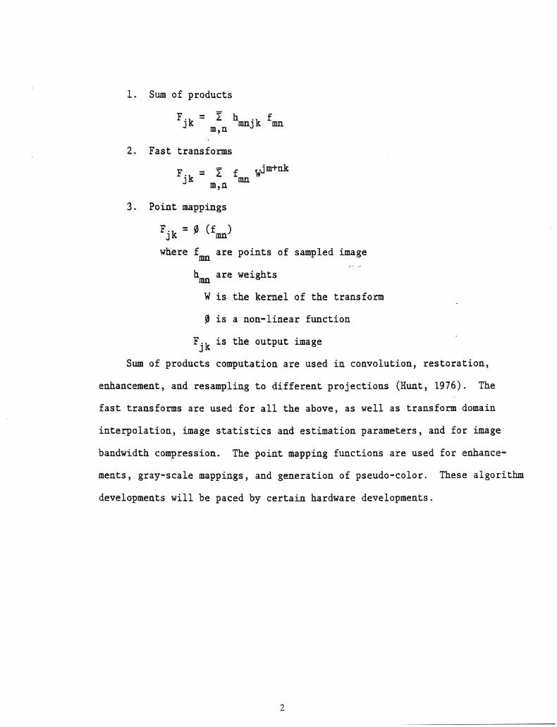
1. Sum of products
F.k = ! h 'k f J IDnJ mn m,n
2. Fast transforms
F.k = ! f Wjm+nk J m,n mn
3. Point mappings
Fjk = ~ (f ) mn
where f mn
are points of sampled image
h mn are weights
w is the kernel of the transform
~ is a non-linear function
Fjk is the output image
Sum of products computation are used in convolution, restoration,
enhancement, and resampling to different projections (Hunt, 1976). The
fast transforms are used for all the above, as well as transform domain
interpolation, image statistics and estimation parameters, and for image
bandwidth compression. The point mapping functions are used for enhance-
ments, gray-scale mappings, and generation of pseudo-color. These algorithm
developments will be paced by certain hardware developments.
2

2.1 Digital Image Processing Hardware Considerations
Special purpose computers are being designed for each of the above
functions (see Figure 1). There are special purpose, highly parallel
computers for certain IP functions. The system described in Figure 1 is
capable of providing the computational power of a CDC 7600 for 250-300K.
The evolution of data base (DB) computers will greatly influence the
design and availability of algorithm development. DB computers will
handle data sets of 109 bits at typical transfer rates of 3xl09 bits per
second to the host or array processor for computational purposes. Real-
time displays are also being considered which will transfer data on the
order of 108 bytes per second through a large multi-port I/0 bus. The
display devices are capable of digital refresh black-and-white imagery
presented at 30 frames per second for 512x512x8 bits and 1024xl024x8 bits
(x3 for color).
For the smaller user though, a more exciting development is the
creation of micro-computer based image processing systems. For example,
a system comprised of a DEC PDP 11/23 with an FPS 100 array processor is
presently being designed, which gives the user the power of a PDP 11/34
at a fraction of the cost. The FPS 100 is an array processor with 300 ns
memory and an instruction set similar to the FPS AP120B. The PDP 11/23
is very similar to the LSI 11 micro-computer except that the 11/23 has
floating point hardware and the full 11/34 instruction set. The price
for this system with appropriate I/0 hardware is on the order of SO-lOOK.
Other low cost systems are being proposed for state and local governments
in the 25 to 30K price range. It is anticipated that once this kind of
hardware is made available to so many users processing remote sensing
information, many new developments in IP will be achieved.
3

' - _______ -·!] OF PRODUCTS COMPUTER
.. lk
+
+:--
I I/0 ~ 1 H~~~ J f
,r --FAST
...,. ... MEMORY I~ .. TRANSFORM .... .. .... .. COMPUTER
~,. .,. I I I I
PO~D I
' I MAPPING I COMPUT~R ' I
t
Figure 1. Specialized IP computing system

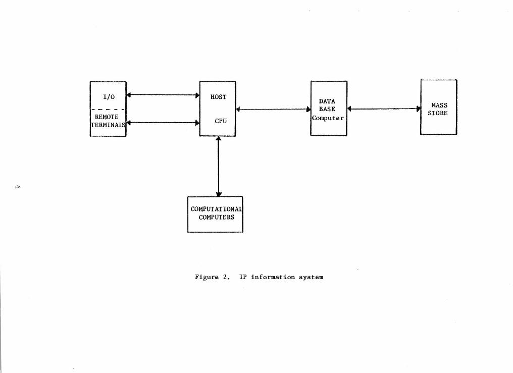
Another hardware development, that will rival the impact array
processors have had on IP, is mass store devices. Once the user has
on-line access to 1013 or 1015 bits of data, it is possible to do multi-
date processing of data on a lot larger volume of information than has
ever been available in the past. Again, IP algorithm development will
occur as people push the information derivation capacity of various
techniques. Image summary statistics will play a much larger role in
deciding what data an algorithm will be exercised on. Mass store systems
are being planned with 1013 to 1015 bits on line with file access time on
the order of 3 to 50 seconds and numerous users on line at once through
host processors. Figure 2 illustrates an example of an IP information
system of the 1980's.
To a certain extent, future planning for larger image processing
computer systems will be driven by higher data rates from improved sensor
resolution. Continual development in the image processing systems (or
data management systems) of the 1980's will stress off-loading certain
processes to front-end displays or specialized hardware to minimize I/0
processing rates. However, with the advent of the combination of micros
and array processors, IP in the low data rate environment will be very
attractive to many users. Continual hardware improvements and the advent
-16 of memory cycle times on the order of 10 seconds through Josephson
circuits will make large systems capable of higher throughput. The
possibility of utilizing, ARPANET, for IP data transfer will also
stimulate IP algorithm development in that it will expose more and more
software designers to parallel coding techniques.
5
I/O :....._ .. ,.. .., HOST
·~---~ ....
DATA ... ._
REMOTE ... • BASE ... MASS
...
TERMINAlS ~· .... CPU Computer
-,. STORE
"PI
4~
0\
lP
COMPUTATION AI COMPUTERS
Figure 2. IP information system
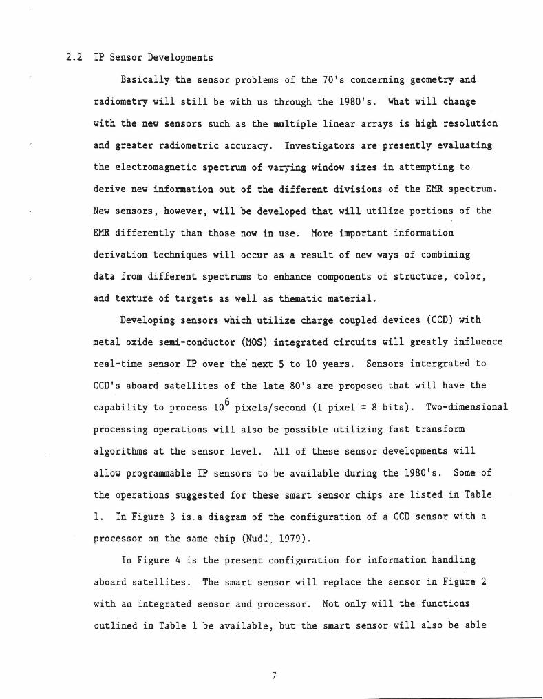
2.2 IP Sensor Developments
Basically the sensor problems of the 70's concerning geometry and
radiometry will still be with us through the 1980's. What will change
with the new sensors such as the multiple linear arrays is high resolution
and greater radiometric accuracy. Investigators are presently evaluating
the electromagnetic spectrum of varying window sizes in attempting to
derive new information out of the different divisions of the EMR spectrum.
New sensors, however, will be developed that will utilize portions of the
EMR differently than those now in use. More important information
derivation techniques will occur as a result of new ways of combining
data from different spectrums to enhance components of structure, color,
and texture of targets as well as thematic material.
Developing sensors which utilize charge coupled devices (CCD) with
metal oxide semi-conductor (MOS) integrated circuits will greatly influence
real-time sensor IP over the· next 5 to 10 years. Sensors intergrated to
CCD's aboard satellites of the late 80's are proposed that will have the
capability to process 106 pixels/second (1 pixel= 8 bits). Two-dimensional
processing operations will also be possible utilizing fast transform
algorithms at the sensor level. All of these sensor developments will
allow programmable IP sensors to be available during the 1980's. Some of
the operations suggested for these smart sensor chips are listed in Table
1. In Figure 3 is.a diagram of the configuration of a CCD sensor with a
processor on the same chip (Nud~, 1979).
In Figure 4 is the present configuration for information handling
aboard satellites. The smart sensor will replace the sensor in Figure 2
with an integrated sensor and processor. Not only will the functions
outlined in Table 1 be available, but the smart sensor will also be able
7

00
TEST CHIP NUMBERS
I
II
Ill
Table 1. IP algorithms integrated to chips (from Nudd, 1979)
PERFORMANCE OPERATIONS AlGORITHMS tcERNEl PER EffECTIVE IMPlEMENTED SIZE PIXEl NUMBER SPEED
OPERATION OF BITS fPIXEl RATEI RATE
EDGt: DETECTaON 3x3 16 .. li kH1 80KOPS HIGH-PASS SPATIAl FILTER 3x3 18 • ti kH1 OOKOPS lAPLACIAN 3x3 13 • 6kH1 66 KOPS 12 dB/APERTURE CORRECTOR 3x3 18 • ti kHJ 80KOPS
SOBEL 3x3 16 • lMHJ 31 MOPS MEAN 3x3 & • lMH1 18 MOPS UNSHARP MASKING 3x3 13 • lMH1 20MOPS BINAIUZATION 3x3 10 • lMH1 20MOPS ADAPTIVE STRETCH 3x3 11 • 2MHJ 24 MOPS
L»LACIAN 3x3 'Ia__ a• 1MHl+ &1 MOPS+
MASIC PROGRAMMABlE 1x1 98 6 JMHJ 630MOPS PROGRAMMABLE 6x5 50 6 lMH1 350MOPS PLUS SHAPED MEDIAN 6 JMH1 BIPOLAR CONVOLUTION 26 X 26 1362 6 lMHz -104 MOPS
' •PRfDICTED PERfORMANCE BASED ON DESIGN
I
&TAlUS I
I
DEVElOPED AND TESTED
DEVELOPED AND TESTED
I
I
I
IN PROCESS

CCD IMAGER
~ CCD PROC
Figure 3. Technique for integrated CCD images and processor
9
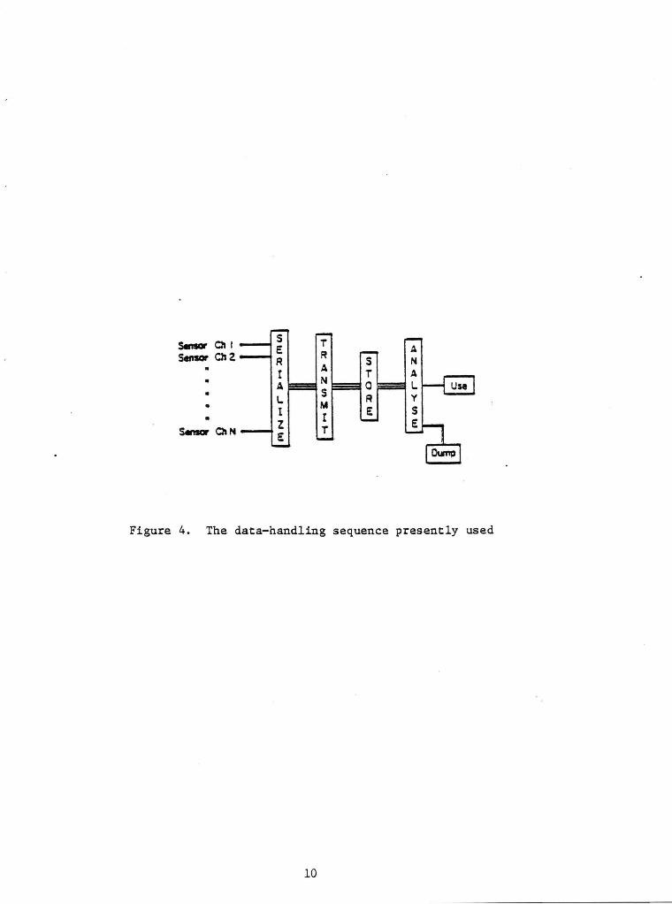
Figure 4. The data-handling sequence presently used
10

to sample the input data and decide aboard the satellite whether to
down-link for further processing or dump. This decision process will
compare stored data either on-board the satellite or up-linked for a
specific pass so that redundant data is not down-linked for processing
(R. Keman, et. al., 1977). Future smart sensors will revolutionize
present modes of sensor data processing. In Figure 5 is a description of
the smart sensor and a pre-processor with an editing or dump function.
3.0 Definitions
Because of some confusion among investigators about terminology in
the areas of IP, definitions of the areas that will be addressed in this
report are given below.
3.1 Coding
The subject of coding basically includes the subsets of data com
pression, formatting, data structures, data bases, and image segmentation.
However, coding generally is the subject of how to create an invertible
transform for a given image. The selected transform should also be more
economical than the original image. This economy is generally expressed
in bits per image or picture element (pixel). A limit of encoding
capability is the original image entropy. Some methods of coding or data
compression give 10 to 1 compression ratios with close to full restoration
capability.
In obtaining image compression through coding, two techniques are
generally used:
1. Fast Fouriers Transforms (FFT) where after the FFT is
computed, the resulting coefficients are observed. Those
coefficients with a magnitude below a certain level are
11
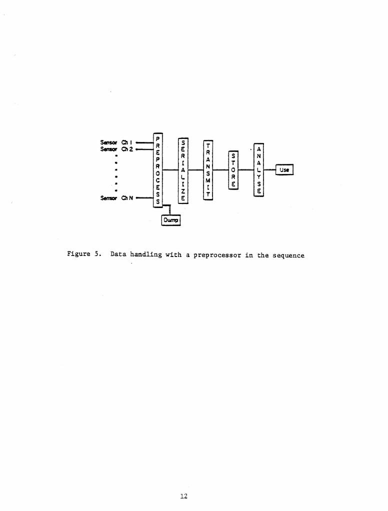
Figure 5. Data handling with a preprocessor in the sequence
12

eliminated. Then the inverse of the FFT is done, recon-
structing the original image. The resultant image minus
the detail of small magnitude, although not fully restored,
does not appear that much different from the original.
2. Difference Methods: Where taking the difference between
samples in either the spatial or tempera! and then
quantizing the results can result in full restoration.
3. Other methods are Huffman and block codes.
3.2 .Restoration
These techniques assume that the observer has knowledge of the
original image. In equation (1),
F5(x,y) = S(s,y) * FI(x,y)
the original image, FI(x,y), is convolved with the sensor function S(x,y)
to produce a sampled image F5(x,y). In restoration methods, A-1 • A
s (x,y) * F5(x,y) = FI(x,y) ~-1 S (x,y) is convolved with the sampled image to produce an estimated
image, FI(x,y). s-1(x,y) is an estimate of the sensor or point spread
function. For restoration methods to be successful, it is anticipated
that the difference e will be small. Of course, the smaller e is, the
better the restoration.
Most of the techniques of restoration are oriented to undoing
degradation of the scene by the sensor and the processing system. Most
of the techniques used, model the degradation to FI(x,y) as additive
combinations of noise, blurring due to focus and motion, and atmospheric
affects. The multiplicative affects such as sun angle are also modeled.
Blurring is a weighted sun or integral operation, and is highly
correlated. Noise, however, is uncorrelated.
13

The various restoration operators are Kalman and other two-
dimensional filters. Also, pseudo-inverse or deconvolution techniques
"-1 are also used (such as S (x,y]). Synthetic line generation is usually
an example of a restoration technique (Bauer, 1978).
Restoration techniques also address the problems of quantitative
radiometric and geometric correction. In radiometric restoration, one
attempts to retain scene signature subtleties with the proper brightness
range. Balance among sensors of the same wavelength is maintained to
avoid banding. Lastly, photographic or shading corrections and pixel
noise reduction are also restoration techniques. As far as geometric
correction as a restoration process is concerned, the main objective is
to register sequential images and to align data with that from other
sources.
The two basic kinds of geometric correction are used for elimination
of internal and external sources of error. The internal sources are made
up of inter-sensor pixel displacement sensor or scanner non-linearities
and horizontal and/or vertical inequalities in pixel spacing. The
external sources are satellite altitude, attitude, projection differences
from a planar to a spherical system, and Earth rotation.
3.3 Enhancement
Enhancement has as its main objective the task of satisfying the
peculiarities and dynamic capabilities of the human observer. Enhance-
ment techniques are basically oriented to an improved display or to
accentuate the visual appearance based on a model of human perception.
Enhancement techniques basically do not contribute to radiometric accuracy.
They can cause geometric inaccuracy when the technique causes a pixel to
be classified in the surround as opposed to the target or vice versa.
14

The enhancement techniques discussed in Section 5.3 essentially
modify the image feature based on a subjective model of how a target
should appear.
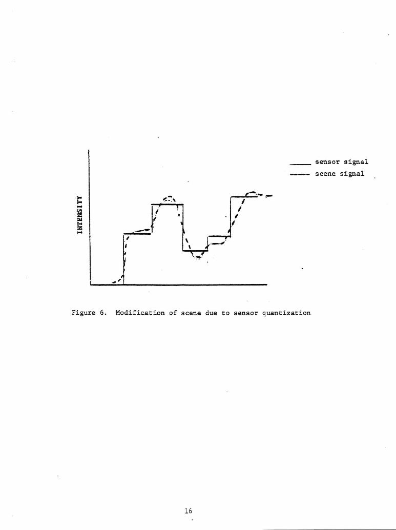
Most of the enhancement techniques entail stretching of the data to
improve the dynamic range and filtering such as high/low pass and medium
filters. The high pass filters restore edges or structural detail that
are lost due to inaccurate or inadequate sampling by the sensor (see
Figure 6). The high pass filter then restores high frequencies that were
altered in the imaging system. One drawback to this method is that it
tends to depress low frequency information while it amplifies the high
frequencies. This is called edge enhancement. Low pass filters preserve
and enhance low frequency information. An example of a low pass filter
is:
/-2-2 ( 1 for ~·X +y <R
F(x,y) = 0 otherwise
where R is a threshold value. The medium filter is used to remove noise
without degradation or smoothing of edges.
Removal of radiometric striping is another area where enhancement
techniques are used. The most effective method is to do a fourier
transform of the image, identify the concentration of energy due to
striping, set the intensity components to zero, and retransform to the
image domain. In summary, basic image enhancement processes are concerned
with the following areas:
1. Noise suppression
2. Removal of distortions
3. Resolution enhancement
15
, I
\ \
I i
I ;
Figure 6. Modification of scene due to sensor quantization
16
sensor signal
scene signal

4. Contrast enhancement
5. Contour enhancement
6. Image blending
3.4 Hardware/Graphics
The hardware and display characteristics of data have been covered
above in Section 1.1. Included for completeness is a short discussion of
graphics, as graphics is considered a subset or a technique of digital
image processing. Some of the most interesting developments in the area
of graphic display are the evolution of encoding in an image digital
information such as elevation. Other typical graphics devices use gridded
information added to the imagery.
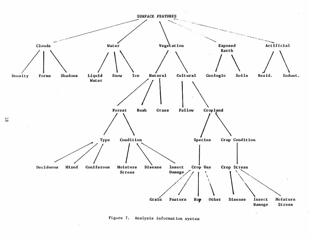
3.5 Image Analysis or Pattern Recognition
This area is basically concerned with the classification and information
extraction techniques. In Figure 7 is the way the scene or object of the
sensor is broken down into classes at different levels. In order to
differentiate to each level, it requires a certain increasing sophistica
tion in either spatial, spectral, or temporal discrimination and increasing
complexity of IP algorithms. The ability to differentiate the scene into
a specific set of distinct classes is a capability of some sensors.
However, IP algorithms do exist that can through either supervised or
unsupervised techniques, classify different scene features. In terms of
user requirements, it is usually identification and mensuration of different
targets that are of utmost importance. · In terms of IP algorithms, it is
of paramount importance that the spatial, spectral, and temporal relation
ships be isolated. Whereas much work has been done in spectral evaluation,
spatial and temporal techniques have not been developed thoroughly. The
problem here is that spatial techniques that separate or classify targets
17
....... (X)
-Clouds
/\ Density Forms Shadows
Deciduous Mixed
SURFACE FEATURES r-- . . . ~ -. . --------....
Water
1\\ I\ Liquid Snow Ice Natural Cultural Water
·,~
, ......... ___
Exposed Earth
-----~--
I \ Geologic Soils
-·-----Artificial
1\ Resid. Indust.
Forest Bush
1\ Grass Fallow lpl\
Condition Species Crop Condition
Coniferous 1\
Moisture Disease Stress
Insect C Damage / rop II Grai// Pasture uar
Figure 7. Analysis information system
Us.e
\
\ Other
Crop Stress
\'·\~ Disease Insect
Damage Moisture Stress

by areal extent are very time consuming for computers (Kirlin, 1980).
Temporal techniques have also not received the development that is required
to make them profitable for pattern recognition. Lack of data availabil
ity has hampered development of temporal techniques. Another temporal
problem is calibration and registration differences that create uncer
tainty in the absence of repetitive data sets. Since cloud cover limits
repetitiveness, temporal techniques have not been adequately developed.
4.0 Overview of On-going IP Activities at Various Institutions
The facilities at CCRS, USC Image Processing Institute, and the
GEOBASE INFORMATION SYSTEM STUDY GROUP are all active in image processing
activities. Reports (see Bibliography) have been generated that discuss
their current activities and outline their future image processing
objectives. These objectives are summarized below.
4.1 IP Activities that are of importance to CCRS are as follows:
1. Develop an on-line quick-look facility for imagery with
remote inquiry stations at regional applications assis
tance facilities. The data from CCRS will be stored
or staged to a digital data system that will transmit
imagery via ANIK-B to remote facilities. There will also
be some communications via land lines with other facilities.
2. Develop a data base or procedure for area selectable
imagery. This activity implies a generalized mosaicking
capability.
3. Develop variable haze map methods for each scene.
19
4. Utilize 70x70 m imagery and develop ground control
point criteria so that 10-20 m location accuracy is
achievable.
5. Investigate requirements from other Earth resources
systems other than Landsat and develop ground processing
systems when a need is demonstrated.
4.2 Santa Barbara Conference
The Santa Barbara Conference on GEOBASE information systems (April,
1978) made the following recommendations concerning development of image
processing algorithms:
l. Evaluate polygonal versus cellular data bases for remote
sensing data. Evaluate the use of gridded information.
2. Document the effects of bi-resampling on classifier
performance for cultural and non-cultural imagery.
3. Develop projection transformations and identify the error
associated with the different cartographic projections.
Development of inter-conversion techniques for reformatting
data from image to map space.
4. Develop a set of "standard" statistics by path/row and
calibrate each path so that radiometry does not vary from
scene to scene.
5. Investigate radiometric and geometric calibration and
feathering techniques where scene overlap occurs.
6. Evaluate data compression techniques for archival and
transmission purposes. These techniques should be
reversible to system noise level.
20
7. Develop cloud cover estimation techniq~es which would
include spatial distribution of cloud cover.
8. Develop the capability for area selectable imagery and
"universal" mosaics.
9. Investigate and document data communication of imagery
via spacecraft and/or land lines.
4.3 USC Image Processing Institute
The following areas are currently being investigated for thesis
material at the Image Processing Institute at USC:
1. Quantitative measures of image quality.
2. "Blind" and non-linear restoration techniques.
3. Development of noise models for image restoration.
4. Figure of merit for boundary detection and edge enhance
ment algorithms.
5. Symbolic image encoding.
6. Generalized brightness cor~ections for mosaicked imagery.
4.4 IP Development at EDC: Basic Requirements
The Systems Development Branch was requested to identify the IP
activities that should be pursued over the next 2-3 years. In order to
identify these activities, it is first important to define the products
needed over the next 2-3 years and then identify those IP techniques
required to provide those identified products. It is proposed that
generalized techniques be used to support many areas at once instead of
developing many product unique techniques for purposes of economy. It is
also felt it would be useful to identify both near and long-term product
lines. A very important additional consideration is what products and
techniques could be developed to satisfy repeatability requirements.
21
Lastly, it is important to identify those products requiring special
versus pipeline techniques or those having an interactive versus batch
flavor.
The areas of product development which were felt important in terms
of priorities listed above with the required techniques are as follows:
1. Geologic/Geographical Analysis
a. Non-cultural products
- Edge enhancement techniques
- Mosaicking
- Stereo and radar data
b. Cultural Products
- Mosaicking
- Improved spatial resolution
GCP and/or RCP activity
- Area selectable data
2. Vegetative Analysis
- Ratio technique
- Brightness masking
- True color (TM)
- Better spectral and spatial resolution
22
3. Shallow Seas Analysis
- Radiometric techniques for improved display of sub
surface and surface phenomena
Low radiance areas of high interest, therefore, noise
removal techniques
- True color (natural or false color w/TM)
- Oil exploration and improved spatial and spectral
resolution
- Emphasis on radiometric technique improvement
4. Meterological Analysis
- Snow melt
- Environmental damage assessment ~.
Quick-look facility and on-line data bases to improve
data timeliness.
In order to evaluate the impact of algorithm development on products
over the next 2-3 years, it is important to define algorithm research and
development activities as well as new hardware and sensor developments.
4.5 IP Algorithm Development at EDC
Areas that seem optimum for algorithm development at EDC are:
1. Projection driver techniques: To produce mosaics and area
selectable imagery expertise in feathering of. overlap
areas (this is a blending technique), surface filter for
variable image sizes, and generalized brightness guide
lines need to be developed.
23
2. Formatting of data: Determining optimal data structures
for feeding CRT, film and tape formats for a variable
product line. This approach might also include symbolic
encoding techniques for transfer of information.
3. Ground control point library development for fitting of
image data. Improvement of spatial resolution will drive
-the development of more accurate Earth location tech
niques of the data. The Stereosat development is assuming
that corrections for platform and ephemeris will be so
4.
accurate that GCP's will not be necessary. However, in
most of the world, the accuracy of the maps is not
sufficient to support GCP. In this event, relative control
points (RCP's) will have to be developed.
Interpolation techniques: Develop techniques to optimally
restore resolution (spatial and spectral) and to take
advantage of over-sampling characteristics.
5. Blending of image data with non-image data. Digital
terrain with MSS data for improved classification (Bauer,
1980).
6. Ratio images: For vegetative vigor and stress detection
as well as water depth mapping.
7. Brightness masked hue · images: For detection of subtle
terrain color differences.
8. High and low pass filter techniques: High pass for
lineament detection and low pass for identifying target
of a low frequency nature such as submerged objects.
24

9. Spatial filtering techniques: For improved classification
in that adjacent pixels have a high probability of belong
ing to the same class.
4.6 Summary of On-going IP Algorithm Development
Advances and applications of new sensors such as the MLA and smart
sensors as well as better spectral and spatial resolution, will drive
many of the developments in IP algorithms. Smart sensors, which integrate
the sensing device with a processor on a chip, will transfer some IP
function to the satellite. Of course, the old problem of users who want
processed versus raw data will continue to plague the ground systems
manager. Additional smart sensor developmen~s are planned for the 80's
where all or most of the present ground processing is done aboard the
satellite. This would include techniques where sensed information for an
area is checked against a data base for that area. If new information
has been sensed, then it is down-linked, otherwise the data is dumped.
The basic reason for this development will be the increase in data rates.
Also, changes in the Data Center itself will affect IP develop
ment. If hardware integration of the major main frames occurs, then
certain IP activities will develop faster. For example, if the EDIPS
could be used as both a pipeline system to Computer Services Branch and
an IDIMS like development system to whoever, more IP functions might be
in an output product mix.
5.0 Future Image Processing Algorithm Developments
5.1 Coding and Techniques
Among the areas where the most intensive algorithm development has
occurred is in bandwidth compression techniques. Most of the data
compression algorithms being developed today, however, do not seem capable
25

of keeping up with the increased data flow forecast for the late 1980's.
For these reasons, mass store systems or a hardware solution is still
envisioned as the most promising solution for the quantity of data.
Along with this technique is the concept of gross information first or
symbolic image encoding. This technique envisions that gross detail can
be summarized before being transmitted to remote sites. What is considered
here is that remote sites will interrogate a data base and gross or
statistical information will be passed to the user before he orders or
accesses the information. The data would be low resolution for this
quick-look information.
Another area of encoding is the creation of data-base design to
effectively store data in appropriate forms for retrieval and display
purposes. Creation of a standard set of sensor data bases for measure
ment of algorithm improvement could also be implemented to solve problems
of standardization. In a related topic to optimal data-base design, is
image segmentation and the creation of what has been identified at EDC as
selectible computer compatible tapes. Related to this is the optimal
projection for various imagery and satellite platforms. The space oblique
mercator (SOM) has been recommended to replace the Hotine oblique mercator
(HOM). Projection on a globe is the ideal since the Earth can be modeled
rather ideally as an ellipsoid. When two-dimensional projection is
required, various algorithms for the projection are utilized. Algorithm
development in this area will continue to seek ways to:
1. Minimize scale distortion
2. Produce conformality
3. Preserve continuity at all latitudes
26

4. Compensate for Earth rotation at higher latitudes
5. Have zones with larger coverage
Once an accurate projection method is available, it is not inconceivable
to put bench-mark data at the end of an image file so that investigators
will have ready made methods to Earth locate the imagery.
5.2 Restoration
Development of quantitative measures of image quality will continue
to be a high priority in algorithm development. Figures of merit for
various restoration are of great importance in providing measures of
improvement. Another area of intense research is "blind" and non-linear
restoration techniques. Greater use of scene statistics, for example,
such as replacing the density values in band 5 of the multi-spectral
scanner with its standard deviation so that one has a ready-made measure
of texture channel is one way to use the present data in a statistically
more meaningful way.
Development of better noise models for restoration purposes will
still be required. Even though sensors with higher SNR will be on-line
in the 1980's, increased resolution will still cause many problems.
Increasing interest in the problems of multiplicative noise models is an
area of active research.
Another area of restoration that is receiving a lot of interest is
interpolation. Mostly those techniques that are now considered inefficient
for present throughput requirements will be utilized more in the future
because of improvements in hardware speed. Especially developments in
parallel or horizontal programming will speed the implementation of
techniques already developed but too time consuming. Also, since over
sampling is used to improve SNR and resolution, new interpolation techniques
will be developed to take advantage of oversampling.
27
In addition to the above, as far as future work on interpolation is
concerned, there are a number of important developments to investigate.
Some of these areas to be investigated are:
1. Because resampling results in an increase of the point
spread function, thus a decrease in resolution, what is
the effect of bi-resampling and what are the optimal
resampling techniques for input to the bi-resampling
process?
2. Create context dependent interpolators that function on
local scene characteristics as opposed to global tech
niques now used.
3. Develop interpolation techniques that are '· shape preserving
techniques. Presently, the histogram changes very little
as a function of shape of interpolator, however, boundaries
of objects in the scene do change.
4. What sort of patterns are added to images as a result
of resampling? That is, develop a figure of merit for
resampling that measures the statistical effect.
5. Quantify the effects of bi-resampling.
6. The effect of bi-resampling on bi-resampled data.
5.3 Enhancement
Figure of merit for boundary detection and edge enhancement ·algorithms
are important areas for developing IP contributions to image understanding.
More spatial enhancement algorithms will be possible in specialized IP
hardware environments of the future. Most of the techniques are scene
dependent. However, new methods will be developed as the analyst develops
a better concept of the underlying structure of the image. There are
28

specific techniques which work quite well for specific problems. However,
general techniques of edge enhancement do not exist that utilize scene
statistics to determine what kernel size and/or filter to utilize.
Since more and better mosaicking capability will be developed, more
rigor will be required to develop generalized brightness corrections for
multiple overlapping imagery.
Another method of analysis that should produce better results is
greater use of spectral and spatial filtering techniques. Better noise
reduction will be possible as generalized Kalman filtering becomes available.
If coded in array processors, most of the IP algorithms will be more
useful and applicable to the small system user. Because of the speed of
the AP, there will be better utilization of the small system.
5.4 Pattern Recognition and Image Analysis
Data integration techniques or correlation of an image with non-image
data will continue to be important for algorithm development. Along with
integration are problems of optimal resolution, registration, and the
techniques of interpolation for missing data points. Also, optimal map
projection for integrated data will spur more work in this area. Other
areas of spatial data integration necessary to support the image analyst
are given below. The following characteristics of spatial data must be
considered:
l. Data format and archival media
2. Resolution, projection, and coordinate system
3. Observational criteria or how the data is grouped and
whether or not it includes interpretative measures
29

4. Accuracy of data
5. Characteristics of sensor, satellite, and atmospheric
path of collected data
Algorithms to take care of the above five points are in great need.
Developing them will necessarily be a rather complex task. In addition,
some measure must be taken of which tasks should be automated versus
those which should remain as manual tasks.
Application of time series techniques will also be an area of develop
ment for classification purposes. Adaptive filters based on two-dimensional
auto-regressive moving average (ARMA) processes are being developed to
create classifications from resultant covariance matrices.
As more and more spatial algorithms are available on processors,
topologically oriented algorithms will be available to evaluate connectivity
of spectral areas as well as consecutivity of the various targets in a
scene.
6.0 Summary
The development of IP algorithms over the next few years will address
many of the same problems seen in the last 10 years (McMurtry, 1980).
The fundamental reason for IP development is to improve the ability to
extract information from data. In the past and the future, algorithm
development will key on spectral, spatial, and temporal variations.
Hardware evolutions as is stated above will pace many of the new develop
ments in IP. More time is being spent on developing the software capability
of present array processors. At the low throughput end, the development
of the FPS 100 will put IP capability at the small user level. At the
other end of the spectrum, the massive parallel processor that Goodyear
is building for NASA/GSFC will see a larger capability for the data rates
of Landsat D and the OERS systems to follow.
30

Even with all the improvements in sensors and ground processing most
errors in IP algorithm are due to the fact that the algorithm makes an
assumption about the scene that on closer inspection is not quite valid.
Most IP algorithm errors are due to misunderstanding of scene components.
Also, most of the algorithm development is related to PR techniques and
no one is actively doing fundamental research. Most researchers are too
busy doing applications. In separating the scene into components for
identification, it is important that:
1. List ·of classes must be cqmplete
2. Classes must have information value
3. Classes must be separable
What the user needs from the algorithm is to be able to recognize a
scene component and measure its extent. These objectives will remain the
same for the forese'eable future. Since there will be more and more
spectral bands Qf different extent on future satellites, it will be
necessary to understand relations between spectral classes in a much more
sophisticated manner. Also, utilizing second and third order statistics
in order to interpret the information in a band will be mandatory. It is
in this area where the technique of principal components will be able to
contribute a lot to our understanding. Principal components analysis
yields a measure of correlation and dependence of various spectral bands
or information channels.
Sensors such as MLA will characterize variations in the scene in a
new way. More spectral channels will enable classifiers to advance
further into the information tree of Figure 7. Better analysis of spatial
variation will be available with increased resolution (10-20 m). Classifi
cation accuracy won't improve greatly over the present results due to
31

resolution alone (Landgrebe, 1976). More class separability will probably
occur, however. Current classification algorithms do not rely that much
on spatial structure as they do on spectral value. Also, improvements in
spatial sampling will occur due to Geostationary Earth Resources Satellites
or more polar orbiting Landsat-type satellites.
Temporal variations will be evaluated as data sets become more
complete. Essentially a good measure of what a target, such as crops, is
can be identified if we can track its stages of development.
6.1 Conclusion
In conclusion, it has been demonstrated that some matching between
the complexity of the data and the complexity of the algorithm will occur
as the spatial, spectral, and temporal characteristics of satellite-borne
sensors are improved. The data will be more complex because of the
increased number of spectral bands, greater SNR, better spatial resolution,
access to scene matching ancillary data, and the availability of multi
temporal data sets.
The requirements for future algorithm development will generally
follow those outlined above. In support of th~se requfrements, IP
algorithm technique development will occur along these paths:
1. Increase of spatially oriented algorithms.
2. Algorithms which will make use of temporal variations
such as time series analysis.
3. Conditional classification algorithms that optimize
discrimination in the feature set.
32
Bauer, B. P.
Sensors.
Bauer, B. P.
Hunt, B. R.
BIBLIOGRAPHY
1980. Considerations for Integrating Data Obtained by Remote
EDC Tech Memo #46.
1979. Synthetic Line Generation. EDC Tech Memo #39.
1976. Computers and Images. SPIE 10SA. Vol. 74.
McMurtry, G. 1980. Private Comm. Penn State Univ.
Keman, R. 1977. Sorting News from Earth-Resources Satellites. NASA Cr.
2869.
Kirlin, Lynn. 1980. Private Communication. Univ. of Wyoming.
Landgrebe, David. 1976. Future of Computer Based Remote Sensing. In Journal
Remote Sensing of Env. Vol. 5, no. 4.
Santa Barbara Conference on GEOBASE INFORMATIONS SYSTEMS. 1978. Univ. of
Calif.
Nudd, G. R. 1979. DEVELOPMENT OF CUSTOM-DESIGNED INTEGRATED CIRCUITS FOR
IMAGE UNDERSTANDING. USCIPI Report Number 910.
33