a study state analysis of mu mimo using adaptive …. 9 issue 5/version-4... · furthermore,...
TRANSCRIPT

IOSR Journal of Electronics and Communication Engineering (IOSR-JECE)
e-ISSN: 2278-2834,p- ISSN: 2278-8735.Volume 9, Issue 5, Ver. IV (Sep - Oct. 2014), PP 11-18 www.iosrjournals.org
www.iosrjournals.org 11 | Page
A Study State Analysis of Mu Mimo Using Adaptive Algorithm
1Venu Madhavi vadagana,
2Mrs. T.D Prashanthi
1M.Tech Student, 2Assistant Professor
Abstract: In conventional cellular systems, each base station (BS) transmits signals intended for a single user
in a particular resource allocation. As bandwidth is a scarce resource, effective utilization of the available
bandwidth in the system is essential in modern wireless systems especially for applications such as video
streaming and voice over internet protocol (VoIP) which demands high data rate. Fortunately since the user’s
feedback the channel state information to the network, there is an opportunity for the BS to schedule more than
one user’s data in a single resource allocation by designing pre-coders which beam form the data to the
intended user. This technique which is called multi-user multiple-input and multiple-output (MU-MIMO) is adopted to investigate an orthogonal frequency-division multiplexing (OFDM)-based downlink transmission
scheme. We develop a analogous fast iterative truncation algorithm (FITRA) and display statistical results to
exhibit tremendous PAR-reduction capabilities. The significantly condensed linearity necessities ultimately
empower the routine of low-cost RF components for the large-scale MU-MIMO-OFDM downlink. We show that
there is a strong preference for obtaining high-quality feedback, and that obtaining near-perfect channel
information from as many receivers as possible provides a significantly larger sum rate than collecting a few
feedback bits from a large number of users.
Keywords: BS, MU-MIMO, OFDM, PAR.
I. Introduction LARGE-SCALE multiple-input multiple-output (MIMO) wireless communication is a promising
means to meet the growing demands for higher throughput and improved quality-of-service of next-generation
multi-user (MU) wireless communication systems [2]. The vision is that a large number of antennas at the base-
station (BS) would serve a large number of users concurrently and in the same frequency band, but with the
number of BS antennas being much larger than the number of users [3], say a hundred antennas serving ten
users. Large-scale MIMO systems also have the potential to reduce the operational power consumption at the
transmitter and enable the use of low-complexity schemes for suppressing MU interference (MUI). All these
properties render large-scale MIMO a promising technology for next-generation wireless communication
systems.
In MU-MIMO operation two or more user environment‟s (UE) share the same time frequency
resources. Several parallel data streams are transmitted simultaneously, one for each UE. It is assumed that the UE feeds back a quantized version of the observed channel, so that base station (BS) can schedule in
MU-MI MO mode terminals with good channel separation. Long term evolution (LTE) and its successor
LTE-Advanced (LTE-A) are some of next generation wireless systems, which use advanced features like
MIMO, link adaptation, orthogonal frequency division multiplexing (OFDM) and many other techniques
to help in achieving high spectral efficiencies.
While the theoretical aspects of large-scale MU-MIMO systems have gained significant attention in the
research community, e.g., [2]–[6], much less is known about practical transmission schemes. As pointed out in
[7], practical implementations of large-scale MIMO systems will require the use of lowcost and low-power
radio-frequency (RF) components. To this end, reference [7] proposed a novel MU precoding scheme for
frequency-flat channels, which relies on per-antenna constantenvelope (CE) transmission to enable efficient
implementation using non-linear RF components. Moreover, the CE precoder of [7] forces the peak-to-average
(power) ratio (PAR) to unity, which is not necessarily optimal as in practice there is always a trade-off between PAR, error-rate performance, and power amplifier efficiency.
The demand for higher speed communications in future wireless cellular networks motivated an
intensive study of multi-antenna transmission techniques which can provide significant performance gains over
conventional single-antenna transmission strategies [14, 15]. Much of the MIMO research in the last decade has
focused on single-user (SU) MIMO techniques where the multiple spatial channels are allocated to a single user
during a given transmission interval. But lately, there is an increasing attention to multiuser (MU)
configurations, where a multi-antenna transmitter serves multiple users over spatially multiplexed channels [16].
Differently from SU MIMO transmissions where channel state information at transmitter (CSIT) is optional, in
MU MIMO CSIT is essential to achieve spatial multiplexing across users.
A Study State Analysis of Mu Mimo Using Adaptive Algorithm
www.iosrjournals.org 12 | Page
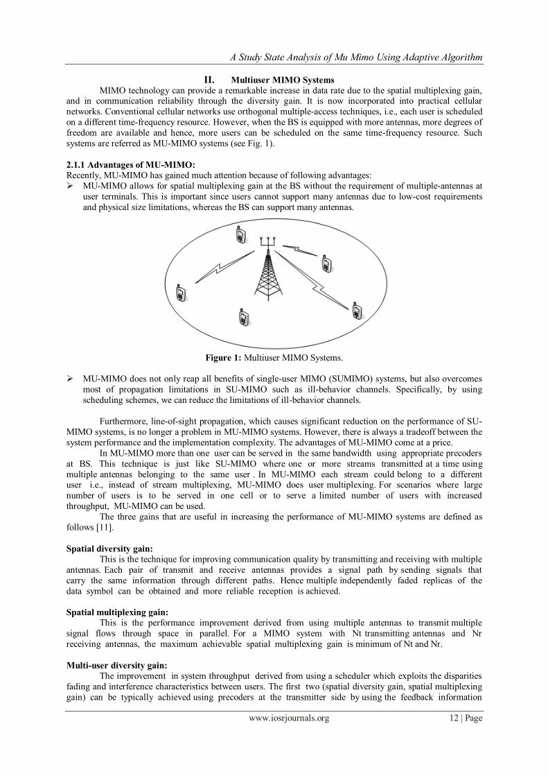
II. Multiuser MIMO Systems
MIMO technology can provide a remarkable increase in data rate due to the spatial multiplexing gain, and in communication reliability through the diversity gain. It is now incorporated into practical cellular
networks. Conventional cellular networks use orthogonal multiple-access techniques, i.e., each user is scheduled
on a different time-frequency resource. However, when the BS is equipped with more antennas, more degrees of
freedom are available and hence, more users can be scheduled on the same time-frequency resource. Such
systems are referred as MU-MIMO systems (see Fig. 1).
2.1.1 Advantages of MU-MIMO:
Recently, MU-MIMO has gained much attention because of following advantages:
MU-MIMO allows for spatial multiplexing gain at the BS without the requirement of multiple-antennas at
user terminals. This is important since users cannot support many antennas due to low-cost requirements
and physical size limitations, whereas the BS can support many antennas.
Figure 1: Multiuser MIMO Systems.
MU-MIMO does not only reap all benefits of single-user MIMO (SUMIMO) systems, but also overcomes
most of propagation limitations in SU-MIMO such as ill-behavior channels. Specifically, by using
scheduling schemes, we can reduce the limitations of ill-behavior channels.
Furthermore, line-of-sight propagation, which causes significant reduction on the performance of SU-
MIMO systems, is no longer a problem in MU-MIMO systems. However, there is always a tradeoff between the
system performance and the implementation complexity. The advantages of MU-MIMO come at a price.
In MU-MIMO more than one user can be served in the same bandwidth using appropriate precoders
at BS. This technique is just like SU-MIMO where one or more streams transmitted at a time using
multiple antennas belonging to the same user . In MU-MIMO each stream could belong to a different user i.e., instead of stream multiplexing, MU-MIMO does user multiplexing. For scenarios where large
number of users is to be served in one cell or to serve a limited number of users with increased
throughput, MU-MIMO can be used.
The three gains that are useful in increasing the performance of MU-MIMO systems are defined as
follows [11].
Spatial diversity gain:
This is the technique for improving communication quality by transmitting and receiving with multiple
antennas. Each pair of transmit and receive antennas provides a signal path by sending signals that
carry the same information through different paths. Hence multiple independently faded replicas of the
data symbol can be obtained and more reliable reception is achieved.
Spatial multiplexing gain:
This is the performance improvement derived from using multiple antennas to transmit multiple
signal flows through space in parallel. For a MIMO system with Nt transmitting antennas and Nr
receiving antennas, the maximum achievable spatial multiplexing gain is minimum of Nt and Nr.
Multi-user diversity gain:
The improvement in system throughput derived from using a scheduler which exploits the disparities
fading and interference characteristics between users. The first two (spatial diversity gain, spatial multiplexing
gain) can be typically achieved using precoders at the transmitter side by using the feedback information

A Study State Analysis of Mu Mimo Using Adaptive Algorithm
www.iosrjournals.org 13 | Page
sent by UE and using multiple antennas. But the latter can be achieved by using proper scheduling
techniques.
MU-MIMO offers additional degrees of freedom when compared to SU-MIMO since multiple users are multiplexed in the same physical channel. This can be achieved by pairing users whose
precoders are orthogonal to each other in a dataregion and then precoding them appropriately so that
each user sees only its own information. As UE feedback quantized channel information, the users will
not be perfectly orthogonal to each other so some remnant inter user interference will be seen by each
of the users who are paired. This can be minimized by using a minimum mean square error (MMSE)
receiver at UE to minimize the effect of multilingual user interference (MUI) on capacity [17].
The main advantages that lead to MIMO paradigm shift to MU-MIMO from SU-MIMO
communications are
1. MU-MIMO schemes allow for direct gain in multiple-access capacity (proportional to number of
transmit antennas) because of multiplexing of data of several users in the same radio channel.
2. MU-MIMO schemes are more immune to loss of channel rank because of line of sight (LOS) conditions or antenna correlation, which is a major problem that causes performance degradation in SU-
MIMO communications.
2.1.2 Challenges:
Channel state information: in order to achieve high spatial multiplexing gain, the BS needs to process the
received signals coherently. This requires accurate and timely acquisition of CSI. This can be challenging,
especially in high mobility scenarios.
There exists multiuser interference, hence complicated interference reduction or cancellation techniques
should be used. For example, maximum likelihood multiuser detection [19] for uplink, dirty paper coding
(DPC) techniques for downlink [20], and interference alignment [21].
Since several users are served on the same time-frequency resource, scheduling schemes which optimally select the group of users depending on the precoding/detection schemes, CSI knowledge etc., should be
considered. This increases the cost of the system implementation.
Pilot contamination: in practical cellular networks, due to the limitation of the channel coherence interval,
non-orthogonal pilot sequences have to be utilized in different cells. Therefore, the channel estimate
obtained in a given cell is contaminated by pilots transmitted by users in other cells. This effect, called
“pilot contamination”, reduces the system performance [22].
MU-MIMO has tremendous benefits which are achieved by overcoming some challenges. Multiple
users using the same resources at the same time would lead to several issues that need to be considered,
some of them are mentioned here.
2.2.1 Interference When multiple users are using the same resources at the same time, there would be severe
interference between their signals. Each user should be capable of decoding his respective stream by
reducing the interference due to other stream. This can be achieved by careful pre-processing at the
transmitter and post-processing at the receiver .
2.2.2 Post-processing
In single-user transmission, MIMO could be used for spatial multiplexing, where multiple
symbols are transmitted to the same user . For example, consider a 2×2 single-user system, in which the
received vector can be represented as
y = Hx + n (2.1)
where the transmitted 2×1 vector x represents 2 symbols that are transmitted simultaneously to
a particular user , thus doubling the user throughput. In order to decode the 2 symbols from the
received 2×1 vector y, a simple approach would be to build a linear receiver that diagonalises the
system, i.e., multiply the received vector y by H−1. This decouples the system and we get back the two
transmitted symbols.
In the MU-MIMO case, the effective received vector y, is a concatenation of the symbols
received by geographically separated users, and post processing must be done in such a way to reduce
the interference from the other user . Several receiver configurations such as MMSE, maximum ratio
combining (MRC) and ZF are possible but MMSE receiver is shown to reduce the interference effectively.

A Study State Analysis of Mu Mimo Using Adaptive Algorithm
www.iosrjournals.org 14 | Page
2.2.3 Pre-processing/precoding
Because of this limitation on the interference cancellation that can be done at the MS, good
precoders need to be designed, such that we beamform efficiently towards the two users. However this would require good knowledge of the channels to both users at the BS, which requires heavy amounts
of feedback. So we would need to come up with the best possible precoders to use at the BS, with a
limitation on the feedback rate.
2.2.4 Channel Quality Indicator (CQI) modeling
CQI is a feedback by the user in frame (n), for the allocation of modulation and coding
schemes in frame (n+1). CQI modeling is to be done so that the user experiences a good throughput.
In the single input single output (SISO) case, CQI is a function of the channel to a particular user ,
which (for low Doppler‟s shift) does not fluctuate much between adjacent frames. But in case of MU-
MIMO, in addition to being a function of the channel to the user, CQI is also a function of the precoder
used at the BS. Hence, better the precoding is lesser is the interference and higher CQI will be.
2.2.5 Scheduling
When we have a number of users contending for same resource, throughputs can be increased
by scheduling those users who experience a good channel. This increase in system performance merely
because of scheduling the best-set of users at any point of time is known as multi-user diversity . However ,
maximizing system throughput must not come as a result of cell-edge users (who face poor channel
conditions) never being scheduled. System performance must be maximized and at the same time a
certain amount of fairness must be ensured among the users in the system. A multi-user scheduler that
meets these demands needs to be implemented.
Zero Forcing Beamforming (ZFBF) and Unitary precoding
ZFBF and unitary precoding are two useful precoding techniques for MU-MIMO in limited feedback environments. ZF precoding is a potential precoder design for MU-MIMO. The main benefit of
ZF scheme is that the interference is pre-cancelled at the transmitter side. It implies that eNodeB has most of
the computational complexity in designing the precoder and each terminal needs only information
regarding its own data streams for reception. However the quantized channel information has to be
precise, so that the multi-user interference becomes sufficiently low in order to get gains from this
scheme. The ZF precoder can be designed using the moore-penrose psuedo inverse as given below (assuming
“u” users are paired together).
(2.2)
Where is the equivalent channel feedback and WT is the precoder used.
2.3.2 Channel Inversion Method and Diagnolization method (BD)
Channel inversion method is one of the linear precoding MU-MIMO techniques which is
simple and has capacity limit. When spatial correlation is increased, the multi-user channel capacity
decreases rapidly. BD can perfectly cancel co-channel interference (CCI), but has antenna constraint at the BS
and MS. The computation burden for system is very heavy when the number of users is very large. Both channel inversion method and BD are based on the feedback of the MIMO channel matrix, so the feedback is
very large. More information about these techniques can be found in [13][14][15].
System Model Digital video broadcast is the technology driving fixed, portable and mobile TV. Since its inauguration
in 1993, digital video broadcast (DVB) project for terrestrial (DVB-T) transmission has fully responded to the
objectives of its designers, delivering wireless digital TV services in almost every continent Error!
Reference source not found.. The main concern of many researchers is to support transmission at higher
data rates with minimum error probability. In 2006, the DVB forum launched a study mission to investigate
what technologies might be considered for a future DVB-T2 standard. It is expected that a multiple input
multiple output (MIMO) system combined with orthogonal frequency division multiplexing (OFDM) should take place for that target. However, it is well known that OFDM systems suffer considerably from carrier
frequency offset (CFO) between transmitter and receiver since CFO includes inter carrier interference (ICI) at
the receiving side Error! Reference source not found..

A Study State Analysis of Mu Mimo Using Adaptive Algorithm
www.iosrjournals.org 15 | Page
This work is carried out within the framework of the European project „Broadcast for the 21st Century‟
(B21C) which constitutes a contribution task force to the reflections engaged by the DVB forum. The main
contribution of this work is twofold. First, a generalized framework is proposed for modelling the effect of CFO on MIMO-OFDM systems. Therefore, we analyze the robustness of different MIMO-OFDM schemes to CFO
using a sub-optimal iterative receiver. This analysis should give a global view on the best suitable MIMO-
OFDM scheme with respect to CFO.
We consider in the downlink communication with two transmit antennas (MT=2) at the base station and
two receiving antennas (MR=2) at the terminal. Figure3.1 depicts the transmitter modules. Information bits bk
are first channel encoded with a convolutional encoder of coding rate R. The encoded, interleaved bits are then
fed to a quadrature amplitude modulation (QAM) module which assigns B bits for each of the complex
constellation points. Therefore, each group s=[s1,…,sQ] of Q complex symbols is encoded through a space time
(ST) block code (STBC) encoder and transmitted during T symbol durations according to the chosen ST
scheme. The ST coding rate is then defined by L=Q/T. With MT transmitting antennas, the output of the ST
encoder is an (MT,T) matrix X=[xi,t] where xi,t (i=1,…,MT; t=1,…,T) is a function of the input symbols sq (q=1,…,Q) depending on STBC encoder type. The resulting symbols are then fed to OFDM modulator of N
subcarriers.
Figure3.1- Block diagram of the transmitter
After D/A conversion, the signal is transposed to the transmitter carrier frequency FTX by the RF unit,
and transmitted through the channel. At the receiver (Error! Reference source not found.), it is
transposed to base band with the receiver carrier frequency FRX and sampled at sampling frequency Fs=1/Ts. In this work, we assume equal carrier frequencies FTX for all transmitting antennas and equal carrier frequencies
FRX for all receiving antennas. The carrier frequency offset is therefore given by F= FRX - FTX. After OFDM demodulation, the signal received by the jth antenna at each time sample t on the nth subcarrier could be written
as:
1 1
,
0 0
1[ , ] [ , ] [ ] , [ , ]
TM N
j i j i j
m pT
y n t x p t h p n p w n tM
(1)
where hj,i[p] is the frequency channel coefficient on the pth subcarrier assumed constant during T
OFDM symbols, Wj[n] is the additive white Gaussian noise (AWGN) with zero mean and N0/2 variance. (n,p) is a function of the CFO, given by:
NpnFTN
pnFTN
Nepn
s
spnFTN
N
Nj s
/)(sin
)(sin1),(
)(1
(2)
The signal received by the MR antennas on sub-carrier n are gathered in a matrix Y[n] of dimension
(MR,T). It can be deduced from (1) by:
1
[ ] ( , ) [ ] [ ] ( , ) [ ] [ ] [ ]N
pp n
n n n n n n p p p n
Y H X H X W
1
[ ] [ ] ( , ) [ ] [ ] [ ]N
pp n
n n n p p p n
eqH X H X W (3)
In (3), the first term represents useful signal, the second term indicates the ICI and the last one is the
AWGN. (n,n) can be seen as a phase rotation and an amplitude distortion of the useful signal due to CFO. The ICI could be seen as an additive noise to the useful signal. It will be
Consider the symbol sampled and complex baseband equiv alent model of a wireless narrow-band
MIMO communication system depicted in Figure 3.3. There are M transmit antennas, N receive antennas and n
denotes the integer-v alued sample index. The frequency non-selective fading MIMO channel at discrete time
instant n is represented by the N ×M matrix H(n) with complex-valued elements Hkl (n), k = 1, · · · , N , l = 1, · · · , M , where Hkl (n) represents the channel between the lth transmit and the kth receive antenna.
Source Encoder Interleaver MapperSTBC
Encoder
OFDM
Mod.
OFDM
Mod.
Ant. 1
Ant. MTkb S
RF Unit
FTX
RF Unit
FTX
Source Encoder Interleaver MapperSTBC
Encoder
OFDM
Mod.
OFDM
Mod.
Ant. 1
Ant. MTkb S
RF Unit
FTX
RF Unit
FTX

A Study State Analysis of Mu Mimo Using Adaptive Algorithm
www.iosrjournals.org 16 | Page
Fig 3.3: MIMO System Model
Channel side information is available at the transmitter. The side information comes in the form of a
time-v arying vector ζ (n) which is statistically related to H(n) in the sense that {ζ (n)} and {H(n)} are assumed
to be jointly stationary and ergodic random processes. A spacetime encoder maps the message to be transmitted
and the side information into M parallel streams of channel symbols by choosing a codeword to transmit out of a set of codewords in a codebook. The codebook corresponds to the channel code. The channel symbols at time
instant n are
represented by the output vector
(15)
which is assumed to satisfy the power constraint
Adaptation of the transmission to variations in the channel conditions is facilitated by the assumption
of an encoder output that is allowed to depend on past and present side information. In other words, c(n) is a
function of {ζ (k)}, k=−∞ (causal side information), in addition to its dependence on the message to be
communicated. The resulting information carrying signals are transmitted over the wireless channel, picked up
by the receiver‟s antenna array and thereafter filtered and symbol sampled to produce the received signals. The
complex baseband equivalent received signals are represented by the vector
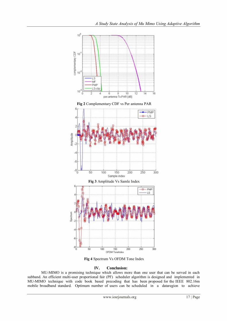
III. Outputs
Fig 1 Average SER vs SNR
A Study State Analysis of Mu Mimo Using Adaptive Algorithm
www.iosrjournals.org 17 | Page
Fig 2 Complementary CDF vs Per antenna PAR
Fig 3 Amplitude Vs Samle Index
Fig 4 Spectrum Vs OFDM Tone Index
IV. Conclusion: MU-MIMO is a promising technique which allows more than one user that can be served in each
subband. An efficient multi-user proportional fair (PF) scheduler algorithm is designed and implemented in
MU-MIMO technique with code book based precoding that has been proposed for the IEEE 802.16m
mobile broadband standard. Optimum number of users can be scheduled in a dataregion to achieve

A Study State Analysis of Mu Mimo Using Adaptive Algorithm
www.iosrjournals.org 18 | Page
maximum sum capacity, which is equal to minimum number of antennas at the base station and the
mobile station.
As for the constant-envelope precoder in [7], the fundamental motivation of PMP is the large number of DoF offered by systems where the number of BS antennas is much larger than the number of terminals
(users). Essentially, the downlink channel matrix has a high-dimensional null-space, which enables us to design
transmit signals with “hardware-friendly” properties, such as low PAR. In particular, PMP yields per-antenna
constant-envelope OFDM signals in the large-antenna limit, i.e., for N → ∞. PMP is formulated as a convex
optimization problem for which a novel efficient numerical technique, called the fast iterative truncation
algorithm (FITRA), was devised.
The sum capacity increases linearly with SNR (db) when the number of users paired is not greater
than the minimum of the number of antennas at the BS and MS i.e. when K < min {M, N} then sum capacity
increases linearly, otherwise it saturates at some other point. From the results discussed in the previous
chapter, multiple users can be paired in a dataregion resulting in higher sum capacity. In addition, we
observe that as the number of user‟s increases, the sum capacity decreases. Moreover, a detailed analysis of the impact of imperfect channel state information on the performance of PMP is left for future work.
References [1]. Aboulnasr Hassanien, “Phased-MIMO Radar: A Tradeoff Between Phased-Array and MIMO Radars,” IEEE TRANSACTIONS
ON SIGNAL PROCESSING, VOL. 58, NO. 6, JUNE 2010
[2]. E. Brookner, “Phased-Array Radars,” Sci. Am. 252(2), 1985, pp. 94–102.
[3]. E. Fishler, A. Haimovich, R. Blum, L. J. Cimini, D. Chizhik and R. Valenzuela, “Spatial Diversity in Radars – Models
and Detection Performance”, IEEE Transactions on Signal Processing, vol. 54, no. 3, pp.823-838, Mar. 2006
[4]. N.H. Lehman, E. Fishler, A.M. Haimovich, R.S. Blum, D. Chizhik, L.J. Cimini, R. Valenzuela, “Evaluation Of Transmit
Diversity In MIMO-Radar Direction Finding”, IEEE Transactions On Signal Processing, vol. 55, no. 5, pp. 2215-2225, May
2007
[5]. D.R. Fuhrman and G.S. Antonio, “Transmit Beamforming For MIMO Radar Systems Using Partial Signal Correlation”, Proc.
38thAsilomar Conf. Signals, Syst. Comput., vol. 1, pp. 295-299, Nov.2004
[6]. A. Hassanien and S. A. Vorobyov, “Transmit/receive beamforming for MIMO radar with colocated antennas”, in Proc. IEEE Int.
Conf. Acoustics, Speech, and Signal Processing, April 2009, pp. 2089ñ2092.
[7]. W. Forsythe, D. W. Bliss, and G. S. Fawcett, “Multiple-input multipleoutput (MIMO) radar: performance issues”, in Proc.
38thAsilomar Conf. Signals, Syst. Comput., vol. 1, PaciÖc Grove, CA, Nov 2004, pp. 310ñ315.
[8]. J.E. Reed, “The AN/FPS-85 Radar System,” Proc. IEEE 57 (3), 1969, pp. 324–335.