a study on the prediction of dynamic behavior of ... · - 1 - a study on the prediction of dynamic...
TRANSCRIPT

- 1 -
A study on the prediction of dynamic behavior of suspensiondesign for Korean High Speed Train System(KHST)
Kyung-Ryul Chung, Jin-Sung Paik and Johannes Picht
(330-825) 35-3 HongChonri, IbjangMyun, ChonAn, Korea
High Speed Railway Technology R&D Division
Korea Institute of Industrial Technology
Phone : +82-41-589-8251, Fax : +82-41-589-8230
E-Mail : [email protected]
Summary
This paper shows an overview of a prototyped test train system, which consists of two power cars, two
motorized trailers and three trailers. The prototyped test train is being manufactured and will be tested for
acquire key technologies of high speed railway in Korea. During conceptual design phase, dynamic behavior
of train system, bogie assembly including suspension system were checked in order to meet a stability, safety
and ride quality requirements by ADAMS/RAIL V10.1
Using the linearized mathematical model, dynamic behavior of the prototyped test train system and bogie
were checked by frequency domain analysis, and then, nonlinear characteristics were also investigated by time
domain analysis for investigating the detail behavior of key suspension components.
Through the analysis, tracking shift force, wheel load, acceleration of bogie frame & wheelsets etc. reviewed
and feedbacked to improve the design parameters.
The optimizations of lateral and yaw damper were already performed to improve the dynamic behavior,
however, detail evaluation will be done during production/test procedure.
Dynamic simulation was performed for middle car group model, which equipped with eddy-current brake
unit(ECBU) to assess its influence of ECBU of trailer bogie
Keywords : Prototyped test train system, Power bogie, Trailer bogie, Suspension system, Bogie system,
Eddy-current brake unit(ECBU)
1. INTRODUCTION
The conceptual design technology of train system in initial design stage[1] is at the core of system
engineering, which is essential to competitiveness of international railway market.
However, Korean railway industries have never designed a high speed train system by themselves, and then,
they always needed an assitance from outside experts or companies. Due to lack of system engineering
technology for designing a new train system, the products are less competitive than the others. To overcome
this drawback, KITECH(Korea Institute of Industrial Technology) in cooperation with KRRI(Korea Railway
Research Institute) is developing a new high speed train in order to acquire key technologies and lead a high
speed railway project in the future[2][3]. The project will continue until October 31, 2002, and the prototyped
test train will be tested on a high speed line in Korea up to 350 km/h. The prototyped high speed test train,
- 2 -
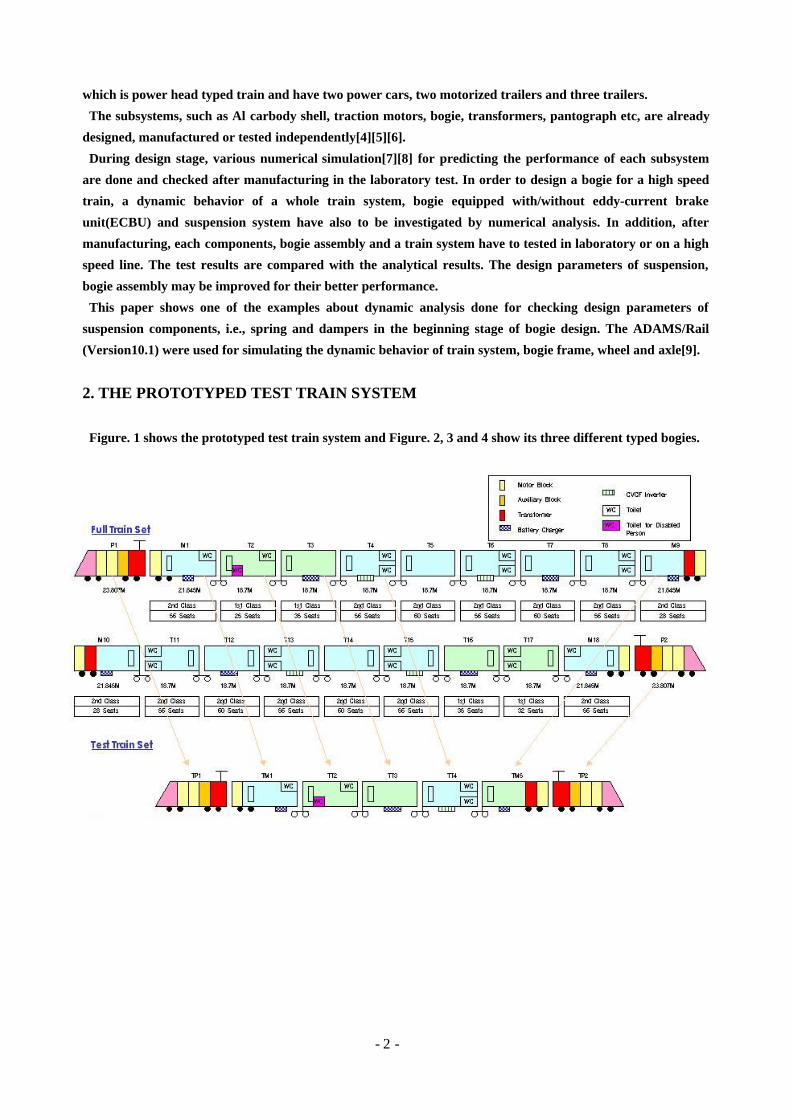
which is power head typed train and have two power cars, two motorized trailers and three trailers.
The subsystems, such as Al carbody shell, traction motors, bogie, transformers, pantograph etc, are already
designed, manufactured or tested independently[4][5][6].
During design stage, various numerical simulation[7][8] for predicting the performance of each subsystem
are done and checked after manufacturing in the laboratory test. In order to design a bogie for a high speed
train, a dynamic behavior of a whole train system, bogie equipped with/without eddy-current brake
unit(ECBU) and suspension system have also to be investigated by numerical analysis. In addition, after
manufacturing, each components, bogie assembly and a train system have to tested in laboratory or on a high
speed line. The test results are compared with the analytical results. The design parameters of suspension,
bogie assembly may be improved for their better performance.
This paper shows one of the examples about dynamic analysis done for checking design parameters of
suspension components, i.e., spring and dampers in the beginning stage of bogie design. The ADAMS/Rail
(Version10.1) were used for simulating the dynamic behavior of train system, bogie frame, wheel and axle[9].
2. THE PROTOTYPED TEST TRAIN SYSTEM
Figure. 1 shows the prototyped test train system and Figure. 2, 3 and 4 show its three different typed bogies.

- 3 -
Figure 1 : Protoyped test train system
Figure 2 : Power bogie Figure 3 : Power bogie Figure 4 : Trailer bogie
for power car for motozed car for traile car
A power bogie for power car have two traction motors, motor & axle gear reduction unit(transmission unit),
primary suspension with guide spring, secondary suspension with coil spring, tread brake unit and air brake
assembly. A power bogie for motorized car also have two traction motors, motor & axle gear reduction
unit(transmission unit), primary suspension with elastic joint, secondary suspension with air spring, wheel
disk brake unit and anti-roll bar device.
A trailer bogie for trailer car is a articulation bogie which is designed with an emphasis on stability during
high speed operation, improved riding comfort and weight reduction and have primary suspension with
elastic joint, secondary suspension with air spring, axle disk brake unit, eddy-current brake unit and anti-roll
bar device. The details are shown in Table. 1
- 4 -
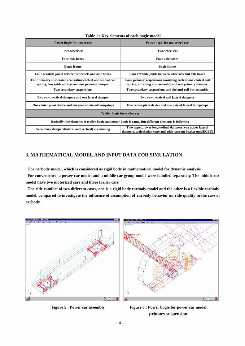
Table 1 : Key elements of each bogie model
Power bogie for power car Power bogie for motorized car
Two wheelsets Two wheelsets
Four axle boxes Four axle boxes
Bogie frame Bogie frame
Four revolute joints between wheelsets and axle boxes Four revolute joints between wheelsets and axle boxes
Four primary suspensions consisting each of one central coilspring, two guide springs and one primary damper
Four primary suspensions consisting each of one central coilspring, a trailing arm assembly and one primary damper
Two secondary suspensions Two secondary suspensions and the anti-roll bar assembly
Two yaw, vertical dampers and one lateral damper Two yaw, vertical and lateral dampers
One center pivot device and one pair of lateral bumpstops One center pivot device and one pair of lateral bumpstops
Trailer bogie for trailer car
Basically, the elements of trailer bogie and motor bogie is same. But different elements is following
Secondary dampers(lateral and vertical) are missing Two upper, lower longitudinal dampers, one upper lateraldampers, articulation cone and eddy-current brakes unit(ECBU)
3. MATHEMATICAL MODEL AND INPUT DATA FOR SIMULATION
The carbody model, which is considered as rigid body in mathematical model for dynamic analysis.
For convenience, a power car model and a middle car group model were handled separately. The middle car
model have two motorized cars and three trailer cars
The ride comfort of two different cases, one is a rigid body carbody model and the other is a flexible carbody
model, compared to investigate the influence of assumption of carbody behavior on ride quality in the case of
carbody.
Figure 5 : Power car assembly Figure 6 : Power bogie for power car model,
primary suspension

- 5 -
Figure 7 : Middle car group assembly Figure 8 : Power bogie for motorized car template
Figure 9 : Power bogie for motorized car model, Figure 10 : Power bogie for motorized car model,
primary suspension anti-roll bar assembly
- 6 -
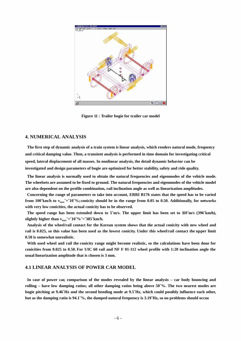
Figure 11 : Trailer bogie for trailer car model
4. NUMERICAL ANALYSIS
The first step of dynamic analysis of a train system is linear analysis, which renders natural mode, frequency
and critical damping value. Then, a transient analysis is performed in time domain for investigating critical
speed, lateral displacement of all masses. In nonlinear analysis, the detail dynamic behavior can be
investigated and design parameters of bogie are optimized for better stability, safety and ride quality.
The linear analysis is normally used to obtain the natural frequencies and eigenmodes of the vehicle mode.
The wheelsets are assumed to be fixed to ground. The natural frequencies and eigenmodes of the vehicle model
are also dependent on the profile combination, rail inclination angle as well as linearization amplitudes.
Concerning the range of parameters to take into account, ERRI B176 states that the speed has to be varied
from 100 km/h to vmax + 10 %; conicity should be in the range from 0.05 to 0.50. Additionally, for networks
with very low conicities, the actual conicity has to be observed.
The speed range has been extended down to 5 m/s. The upper limit has been set to 110 m/s (396 km/h),
slightly higher than vmax + 10 % = 385 km/h.
Analysis of the wheel/rail contact for the Korean system shows that the actual conicity with new wheel and
rail is 0.025, so this value has been used as the lowest conicity. Under this wheel/rail contact the upper limit
0.50 is somewhat unrealistic.
With used wheel and rail the conicity range might become realistic, so the calculations have been done for
conicities from 0.025 to 0.50. For UIC 60 rail and NF F 01-112 wheel profile with 1:20 inclination angle the
usual linearization amplitude that is chosen is 3 mm.
4.1 LINEAR ANALYSIS OF POWER CAR MODEL
In case of power car, comparison of the modes revealed by the linear analysis – car body bouncing and
rolling – have low damping ratios; all other damping ratios being above 50 %. The two nearest modes are
bogie pitching at 9.46 Hz and the second bending mode at 9.5 Hz, which could possibly influence each other,
but as the damping ratio is 94.1 %, the damped natural frequency is 3.19 Hz, so no problems should occur.

- 7 -
Figure 12 : Root locus plot for conicity 0.025(Power car)
At the design conicity 0.025 for new wheel and rail, the yaw mode of the car body shows negative damping at
speeds above 82 m/s. The corresponding natural frequency is 1.2 Hz at 110 m/s. All other eigenmodes stay well
above 5 % damping ratio.
The negative damping of the body yaw mode indicates some form of instability, albeit with a rather low
frequency. Bogie instabilities would rather be expected at above 4 Hz. Whether this mode is critical – actually
being excited – can only be seen in the nonlinear analysis.
4.2 LINEAR ANALYSIS OF MIDDLE CAR GROUP MODEL
In case of middle car group model, comparison of natural modes of the vehicle model and flexible carbody
shows that the lowest damping ratios are above 12 %. Two frequency pairs seem to lie quite close to each
other. The bouncing of the motorized bogies 1 and 6 at about 7.9 Hz and the first car body bending mode at
8.1 Hz could possibly influence each other, but the bogie mode has a quite high damping ratio of 46 %. This
should not be a too great concern. The rolling of the articulated bogies 2 – 5 at around 20.4 Hz and the 2nd
torsion mode at 19.8 Hz could possibly influence each other. This might require some closer checking.
At the design conicity 0.025 for new wheels and rails basically two modes show negative or marginal
damping. One is a complicated mix of lateral car body movement and bending, car body yawing and lateral
movement of the leading bogie. This mode has negative damping from slightly below 30 m/s, reaches lowest
damping ratio at 55 m/s and –9 %, then shows increasing damping ratios – finishing at 110 m/s, 0.6 Hz and

- 8 -
–2.5 %. The other one is four closely neighbouring modes, which show decreasing damping ratios as speed
increases. All mostly feature lateral and yawing motions of the four articulated bogies, with different
amplitudes and phase angles.
Figure 13 : Root locus plot for conicity 0.025(Middle car group)
Two of these modes cross the 0 %-line just below 110 m/s, at frequencies around 1.4 Hz. The negative damping
of these modes indicates some form of instability, albeit with a rather low frequency. Bogie instabilities would
rather be expected at above 4 Hz. Whether this mode is critical – actually being excited – can only be seen in the
nonlinear analysis.
5. NONLINEAR ANALYSIS
The nonlinear analysis gives the deepest insight into the vehicle behaviour. It is not restricted to simple
stable vs. non-stable decisions, but gives information about mechanical quantities such as forces,
accelerations and displacements.
The nonlinear analysis is performed in the time domain and takes into account the full vehicle model
including wheel/rail contact and the influence of disturbed track. Disturbed track has been measured on
section of high speed line in Korea.
The present calculations have been done under the following condition.

- 9 -
Table 2 : Conditions of nonlinear analysisItems Conditions
Curvature Straight track, 7000 m
Cant in curve 90, 120, 150, 180 m
Track in irregularity Line speed 270 km/h - gauge 1435 mm, 0-1km
Track gauge 1435, 1432 mm on straight track1435 mm on curved track
Rail profile UIC60 (1:20)
Wheel profile 1/40 NF F 01-112, wheel back to back distance 1356 mm
Velocity50, 60, 70, 80, 90, 100, 110 m/s on straight track(power car)70, 80, 90, 100, 110 m/s on straight track(middle car)100 m/s on curved track(both power and middle car)
Loading condition Power car in service conditionMiddle car empty on straight track, fully loaded on curves
Lateral non-compensated accelerationon curved track 0.84, 0.64, 0.45, 0.25 m/s2(decreasing with increasing cant)
A nonlinear simulation has been performed for each of the resulting variations. All quantities are filtered
according to UIC 518. The time histories of each simulation run are statistically analyzed.
5.1 NONLINEAR ANALYSIS RESULT OF POWER CAR MODEL INSTRAIGHT/CURVED TRACK
In this case the lateral wheelset and bogie frame accelerations remain comparatively small. The vertical
accelerations of the car body and derailment quotient stay small as well.
Table 3 : Nonlinear analysis result of power car model in straight/curved trackStraight track Curved track(cant 90 mm)
Items Assessment criteria110 m/s 110 m/s
Track shiftingforce(99.85%)
64 [kN] 28.8 53.3
Derailmentquotient(99.85%)
0.8 0.227 0.356
Wheel load(99.85%) 160 [kN] 151 153
Lateralacceleration(99.85%)
2.5 [m/s2] 1.02 1.04
Verticalacceleration(99.85%)
2.5 [m/s2] 1.87 1.56
Lateral acceleration(rms) 0.5 [m/s2] 0.349 0.289
Vertical acceleration(rms) 1.0 m/s2 0.585 0.521
5.2 NONLINEAR ANALYSIS RESULT OF MIDDLE CAR GROUP MODEL INSTRAIGHT/CURVED TRACK
The results show some improvements in the critical area(wheel/rail forces). Too high wheel load forces
occur on straight track at 100 m/s and on curved track at 90 m/s, indicating that wheel lift-off happens.
On straight track at 90 m/s all results are below the limits, at 100 m/s only the wheel load forces exceed the

- 10 -
limit. On curved track at 90 m/s only the wheel load forces exceed the limit, at 100 m/s the derailment
quotient ae well is slightly too high
Table 4 : Nonlinear analysis result of middle car group model in straight/curved trackStraight track Curved track(cant 90 mm)
Items Assessment criteria90 m/s 100 m/s 90 m/s 100 m/s
Track shiftingforce(99.85%)
56 [kN] 37.4 65.9 67.4 90.6
Derailmentquotient(99.85%)
0.8 0.363 0.527 0.459 0.813
Wheel load(99.85%) 160 [kN] 130 232 200 224
Lateralacceleration(99.85%)
2.5 [m/s2] 0.636 0.832 0.676 1.17
Verticalacceleration(99.85%)
2.5 [m/s2] 0.417 0.477 0.513 0.63
Lateral acceleration(rms) 0.5 [m/s2] 0.158 0.265 0.190 0.329
Vertical acceleration(rms) 0.75 m/s2 0.077 0.082 0.090 0.113
5.3 NONLINEAR ANALYSIS RESULT OF MIDDLE CAR GROUP MODEL WITHEDDY-CURRENT BRAKE UNIT (ECBU) IN STRAIGHT TRACK
To assess the influence of ECBU of trailer bogie, nonlinear analysis were performed for middle cargroup model which equipped with ECBU. Figure. 14 show the schematic of ECB frame.
Figure 14 : Eddy-current brake frame(weight : 920 kg)
The calculation for the middle car group model with ECBU was done at a speed of 100 m/s. The braking

- 11 -
forces led to a decelaration of about 0.35 m/s2, then, the speed researched 86.5 m/s after 4 km/h. The results for the middle car with ECBU at high speed differ only slightly from those for the middle carwithout ECBU. This is due to the relatively small force which ECBU produces at high speed.
Table 6 : Nonlinear analysis result of middle car with ECBU in straight trackStraight track
Items Assessment criteria 100 m/s[without ECBU]
100 m/s[with ECBU]
Track shiftingforce(99.85%)
56 [kN] 65.9 45.4
Derailmentquotient(99.85%)
0.8 0.527 0.381
Wheel load(99.85%) 160 [kN] 232 150
Lateralacceleration(99.85%)
2.5 [m/s2] 0.832 0.769
Verticalacceleration(99.85%)
2.5 [m/s2] 0.477 0.327
Lateral acceleration(rms) 0.5 [m/s2] 0.265 0.242
Vertical acceleration(rms) 0.75 m/s2 0.082 0.074
6. CONCLUSIONS
This paper shows an overview of a prototyped test train system, which are being manufactured in the
project for developing a new high speed train system in Korea. The dynamic behavior of a prototyped
test train, bogie and suspension components were performed for reviewing the basic design of the bogies
and their suspension. Dynamic analysis also has been performed for middle car group model, whose bogie
are equipped with ECBU in order to assess the influence of ECBU of trailer bogie
Using the linearized mathematical model, dynamic behavior of the prototyped test train system and
bogie were checked by frequency domain analysis, and then, nonlinear characteristics were also
investigated by time domain analysis for investigating the detail behavior of key suspension components.
Through the analysis, tracking shift force, wheel load, acceleration of bogie frame & wheelsets etc.
reviewed and feedbacked to improve the design parameters.
The optimizations of lateral and yaw damper were already performed to improve the dynamic behavior,
however, detail evaluation will be done during production/test procedure.
REFERENCES:
[1] K.R. Chung, K.T. Kim, “The Conceptual Design of Korea High Speed Train System”, The Korean
Society for Railway, 1999.11.10, pp 172-180.
[2] K.R. Chung etc., “Development of Train System Engineering Technology”, KITECH Annual report,
1999.
[3] K.R. Chung etc., “Development of Train System Engineering Technology”, KITECH Annual report,
2000.
[4] S.H. Han, B.H. Lee, K.T. Kim, K.R. Chung, “Fundamental Design & Integration of Test Car for Korea

- 12 -
High Speed Train”, The Korean Society for Railway, 1999.11.10, pp 202-208.
[5] K.R. Chung, K.T. Kim, Jurgen Jakob, “Basic Design of High Speed Bogie for Articulated and
Distributed Power Train system”, Proceeding of the Korean Society of Mechanical Engineers Summer
Annual Conference, 2000, pp 496-502, KSME00DC091.
[6] K.R. Chung etc., “The basic design of Korean high speed train system”, WCRR 2001, ID number 321.
[7] K.R. Chung, S.H. Kim, J.S. Paik, T.Schwiegel, “Analysis of Dynamic Behavior of The Korean High
Speed Train”, Proceeding of the Korean Society for Noise and Vibration Engineering Autumn Annual
Conference, 2000, pp 900-910.
[8] K.R. Chung, J.S. Paik, “Analysis of Dynamic Behavior for Design Review of The Korean High Speed
Prototype Test Train”, Proceeding of the Korean Society for Noise and Vibration Engineering Spring
Annual Conference, 2001, pp 1232-1240.
[9] Bombardier Transportation - Talbot, "G7-train Dynamic calculations and Testing", Report for
KITECH 2000.