a strong team for economical concrete paving. slipform
TRANSCRIPT
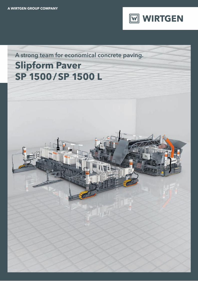
A strong team for economical concrete paving.
Slipform PaverSP 1500 / SP 1500 L

Outstanding features of the SP 1500 slipform paver
PIVOTING LEGS
Pivoting legs for full adjustment of the track units to the conditions prevailing on site.
3 |TRACK UNITS
Hydraulically driven, separately height-adjustable and steerable track units for precise driving behaviour and high-precision concrete paving.
4 |
SUPER SMOOTHER
Super smoother for a perfectly smooth surface finish.
16 |
TOP-LAYER CONCRETE PAVER SP 1500
As top-layer concrete paver in dual-layer concrete paving, the SP 1500 paves the top concrete layer “wet-in-wet”.
1 |
LONGITUDINAL JOINT TIE BAR INSERTER
Automated insertion of longitudinal joint tie bars to prevent concrete slabs from drifting apart.
13 |SIDE TIE BAR INSERTER
Automated insertion of side tie bars when paving adjacent concrete slabs.
14 |
OSCILLATING BEAM
Eccentrically driven oscillating beam for the production of smooth con-crete surfaces.
15 |
BOTTOM-LAYER CONCRETE PAVER SP 1500
As bottom-layer concrete paver in dual-layer concrete paving, the SP 1500 paves the bottom concrete layer.
2 |
16 |
1 |
6 |3 |
4 |
5 |
7 |
9 |
15 |
3 |
14 |
02 03
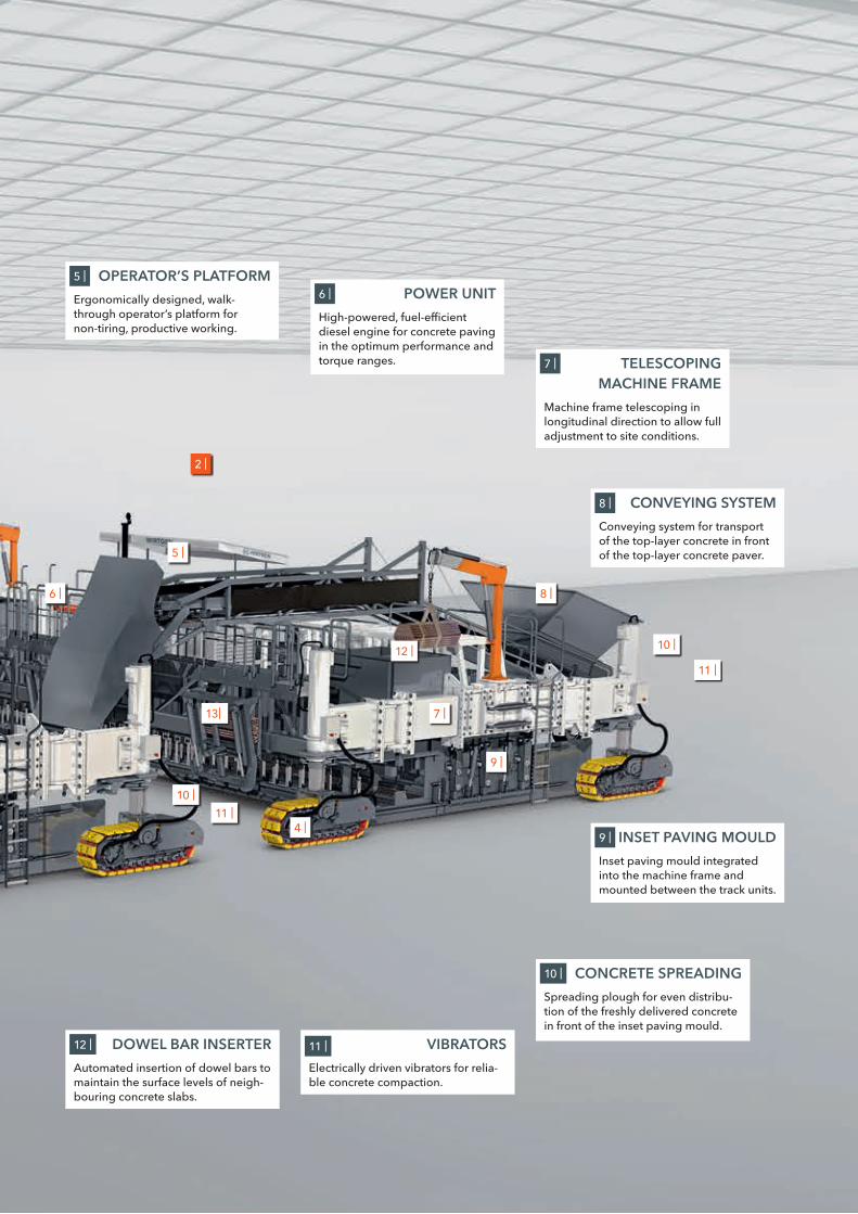
DOWEL BAR INSERTER
Automated insertion of dowel bars to maintain the surface levels of neigh-bouring concrete slabs.
12 | VIBRATORS
Electrically driven vibrators for relia-ble concrete compaction.
11 |
TELESCOPING MACHINE FRAME
Machine frame telescoping in longitudinal direction to allow full adjustment to site conditions.
7 |
CONVEYING SYSTEM
Conveying system for transport of the top-layer concrete in front of the top-layer concrete paver.
8 |
OPERATOR’S PLATFORM
Ergonomically designed, walk-through operator’s platform for non-tiring, productive working.
5 |
POWER UNIT
High-powered, fuel-efficient diesel engine for concrete paving in the optimum performance and torque ranges.
6 |
CONCRETE SPREADING
Spreading plough for even distribu-tion of the freshly delivered concrete in front of the inset paving mould.
10 |
INSET PAVING MOULD
Inset paving mould integrated into the machine frame and mounted between the track units.
9 |
2 |
10 |
11 |
9 |
4 |
10 |
11 |
13|
5 |
6 |
7 |
8 |
12 |

Outstanding features of the SP 1500 L slipform paver
4 |
TRACK UNITS
Hydraulically driven, height-adjust-able track units for precise driving behaviour and high-precision con-crete paving.
3 |
SUPER SMOOTHER
Super smoother for a perfectly smooth surface finish.
14 |
13 |
5 |
LONGITUDINAL JOINT TIE BAR INSERTER
Automated insertion of longitudinal joint tie bars to prevent concrete slabs from drifting apart.
12 |
14 |
OSCILLATING BEAM
Eccentrically driven oscillating beam for the production of smooth con-crete surfaces.
13 |
1 |
TOP-LAYER CONCRETE PAVER SP 1500 L
As top-layer concrete paver in dual-layer concrete paving, the SP 1500 L paves the top concrete layer “wet-in-wet”.
1 |
BOTTOM-LAYER CONCRETE PAVER SP 1500 L
As bottom-layer concrete paver in dual- layer concrete paving, the SP 1500 L paves the bottom concrete layer.
2 |
SIDE TIE BAR INSERTER
Automated insertion of side tie bars when paving adjacent concrete slabs.
11 |
04 05

3 |
DOWEL BAR INSERTER
Automated insertion of dowel bars to maintain the surface levels of neigh-bouring concrete slabs.
10 |
7 |
3 |
4 |
10 |
11 |
CONVEYING SYSTEM
Conveying system for transport of the top-layer concrete in front of the top-layer concrete paver.
6 |
OPERATOR’S PLATFORM
Ergonomically designed, walk-through operator’s platform for non-tiring, productive working.
4 |
POWER UNIT
High-powered, fuel-efficient diesel engine for concrete paving in the optimum performance and torque ranges.
5 |
INSET PAVING MOULD
Inset paving mould integrated into the machine frame and mounted between the track units.
7 |
8 |12 |
7 |
CONCRETE SPREADING
Spreading plough for even dis-tribution of the freshly delivered concrete in front of the inset paving mould.
8 |
8 |
9 |
9 |
VIBRATORS
Electrically driven vibrators for relia-ble concrete compaction.
9 |
2 |
13 |
6 |
5 |
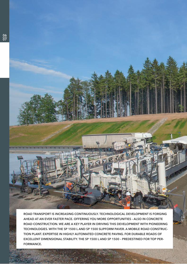
ROAD TRANSPORT IS INCREASING CONTINUOUSLY. TECHNOLOGICAL DEVELOPMENT IS FORGING
AHEAD AT AN EVER FASTER PACE. OFFERING YOU MORE OPPORTUNITIES - ALSO IN CONCRETE
ROAD CONSTRUCTION. WE ARE A KEY PLAYER IN DRIVING THIS DEVELOPMENT WITH PIONEERING
TECHNOLOGIES. WITH THE SP 1500 L AND SP 1500 SLIPFORM PAVER. A MOBILE ROAD CONSTRUC-
TION PLANT. EXPERTISE IN HIGHLY AUTOMATED CONCRETE PAVING. FOR DURABLE ROADS OF
EXCELLENT DIMENSIONAL STABILITY. THE SP 1500 L AND SP 1500 – PREDESTINED FOR TOP PER-
FORMANCE.
06 07
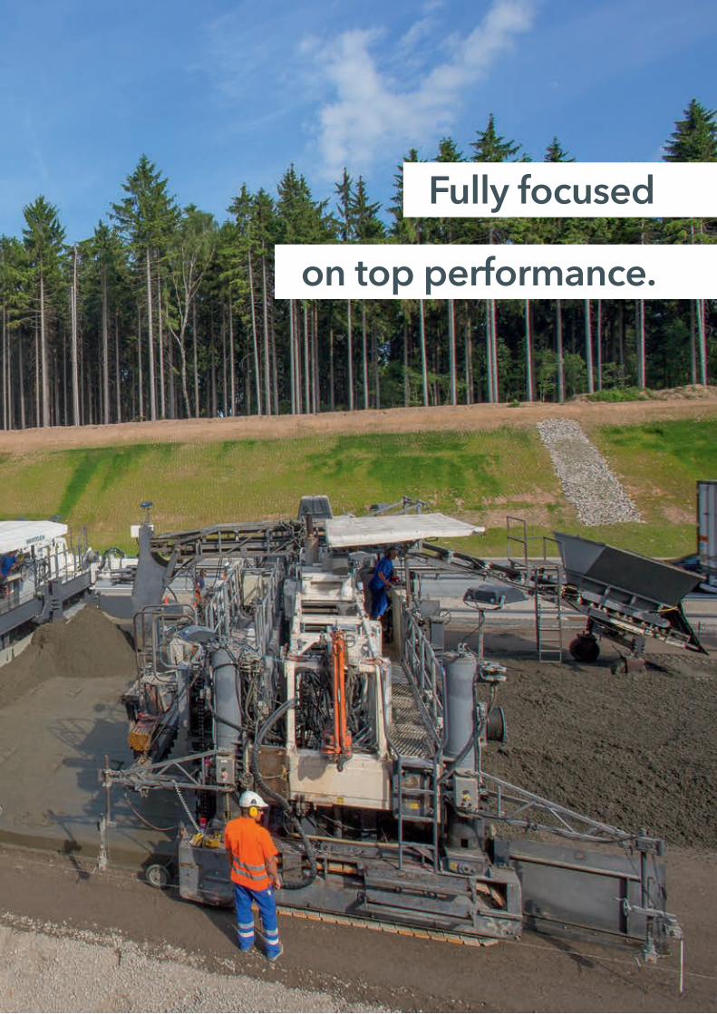
Fully focused
on top performance.

Intelligence in concrete paving:this paving train is a high-speed train
HIGH-QUALITY DUAL-LAYER CONCRETE PAVEMENTS
WIRTGEN uses an efficient, tried-and-tested process for the production of dual-layer concrete pavements: the paving train con-sists of three separate units comprising the bottom-layer paver, top-layer paver and TCM texture curing machine. In the paving process, the SP 1500 / SP 1500 L slipform paver can be used as bottom-layer paver or top-layer paver in accordance with customer specifications.
The intelligent concrete paving process and resulting high daily performance rates, ease of transport and a variety of adjustment options enable the paving train to produce high-quality dual-layer concrete pavements at widths of up to 15.25 m economically and in record time.
The SP 1500 L is equipped with two track units, whilst the SP 1500 features four track units for increased flexibility. Separation of the two paving units ensures ease of transport and requires little effort for setup and disas-sembly. The high degree of automation of the SP 1500 / SP 1500 L additionally results in efficient performance.
Paving two layers of concrete simultaneously is an approved method for the economically efficient production of concrete pavements.
1 |
08 09

1 | Efficient: bottom- layer concrete and top-layer concrete are paved in imme-diate succession.
2 | The SP 1500 L and SP 1500 are used as either bottom-layer paver or top-layer paver in accordance with requirements.
2 |

Bottom-layer concrete paver SP 1500
Top-layer concrete paver SP 1500
CHOICE OF DIFFERENT COMBINATIONS:
Use as required: concrete pavingwith the SP 1500 or SP 1500 L
TWO OR FOUR TRACK UNITS
Depending on requirements, customers can use the SP 1500 with four or the SP 1500 L with two track units as the bottom-layer or top-layer concrete paver. The two-tracked SP 1500 L slipform paver model offers the advantages of lower machine weight and shorter transport length.
The four-tracked SP 1500, on the other hand, offers a significantly larger contact surface, thus effectively pre-venting the machine from sinking in on soft ground. In addition, each of the SP 1500’s four track units can be adjusted, steered and pivoted about 90 degrees separately and hydraulically for improved manoeuvra-bility. Hydraulically adjustable pivoting legs enable track adjustment which allows the SP 1500 to be easily adapted to any fixed obstacles on the paving site.
Being equipped with four track units, the SP 1500 can easily turn on its axis which is helpful, for example, for repositioning or manoeuvring the machine.
10 11

Bottom-layer concrete paver SP 1500 L
Bottom-layer concrete paver SP 1500 L
Top-layer concrete paver SP 1500
Top-layer concrete paver SP 1500 L
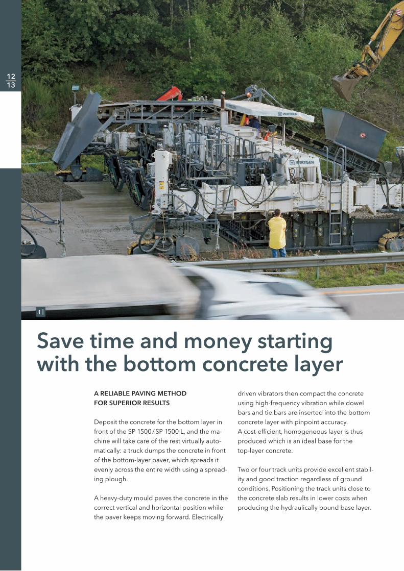
A RELIABLE PAVING METHOD FOR SUPERIOR RESULTS
Deposit the concrete for the bottom layer in front of the SP 1500 / SP 1500 L, and the ma-chine will take care of the rest virtually auto-matically: a truck dumps the concrete in front of the bottom-layer paver, which spreads it evenly across the entire width using a spread-ing plough.
A heavy-duty mould paves the concrete in the correct vertical and horizontal position while the paver keeps moving forward. Electrically
driven vibrators then compact the concrete using high-frequency vibration while dowel bars and tie bars are inserted into the bottom concrete layer with pinpoint accuracy. A cost-efficient, homogeneous layer is thus produced which is an ideal base for the top-layer concrete.
Two or four track units provide excellent stabil-ity and good traction regardless of ground conditions. Positioning the track units close to the concrete slab results in lower costs when producing the hydraulically bound base layer.
Save time and money starting with the bottom concrete layer
1 |
12 13

1 | Economical paving of inexpen-sive bottom-layer concrete at working widths ranging from 5.0 m to 15.25 m.
2 | Sensor for level and steering con-trol; the track unit travels close to the concrete slab.
3 | The spreading plough distributes the previously deposited concrete for the bottom layer across the entire width.
3 |
2 |

No need to interrupt production:automated insertion of dowel bars
TOTAL AUTOMATION HELPS YOU EXPLOIT ALL COST-CUTTING POTENTIAL
The SP 1500 / SP 1500 L has yet another trump card to offer: automated insertion of dowel bars and tie bars into the concrete layer. The dowel bars are inserted parallel, the tie bars perpendicular to the concrete slab by means of vibration. Highlight of the process: the dowel bar inserter mounted on the machine can move in the direction of paving, meaning that it remains above the paving site without interrupting machine travel until the dowel bars have been accurately inserted into the concrete. Dowel bars and tie bars are inserted
in a fully automated process. Labour require-ments for dowel bar distribution are therefore reduced to process monitoring.
Dowel bar and tie bar lengths and intervals can be adapted in accordance with project requirements.
1 |
14 15
3 | 4 |
5 |
2 |
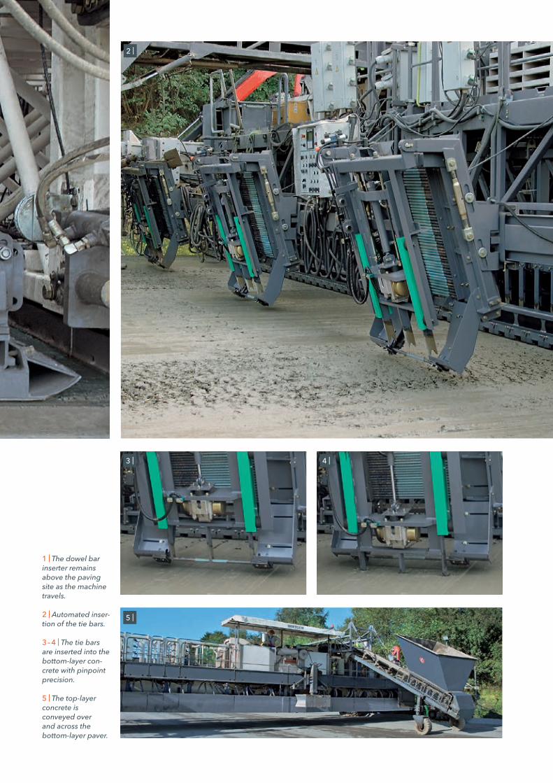
1 | The dowel bar inserter remains above the pavingsite as the machinetravels.
2 | Automated inser-tion of the tie bars.
3 – 4 | The tie bars are inserted into the bottom-layer con-crete with pinpoint precision.
5 | The top-layer concrete is conveyed over and across the bottom-layer paver.
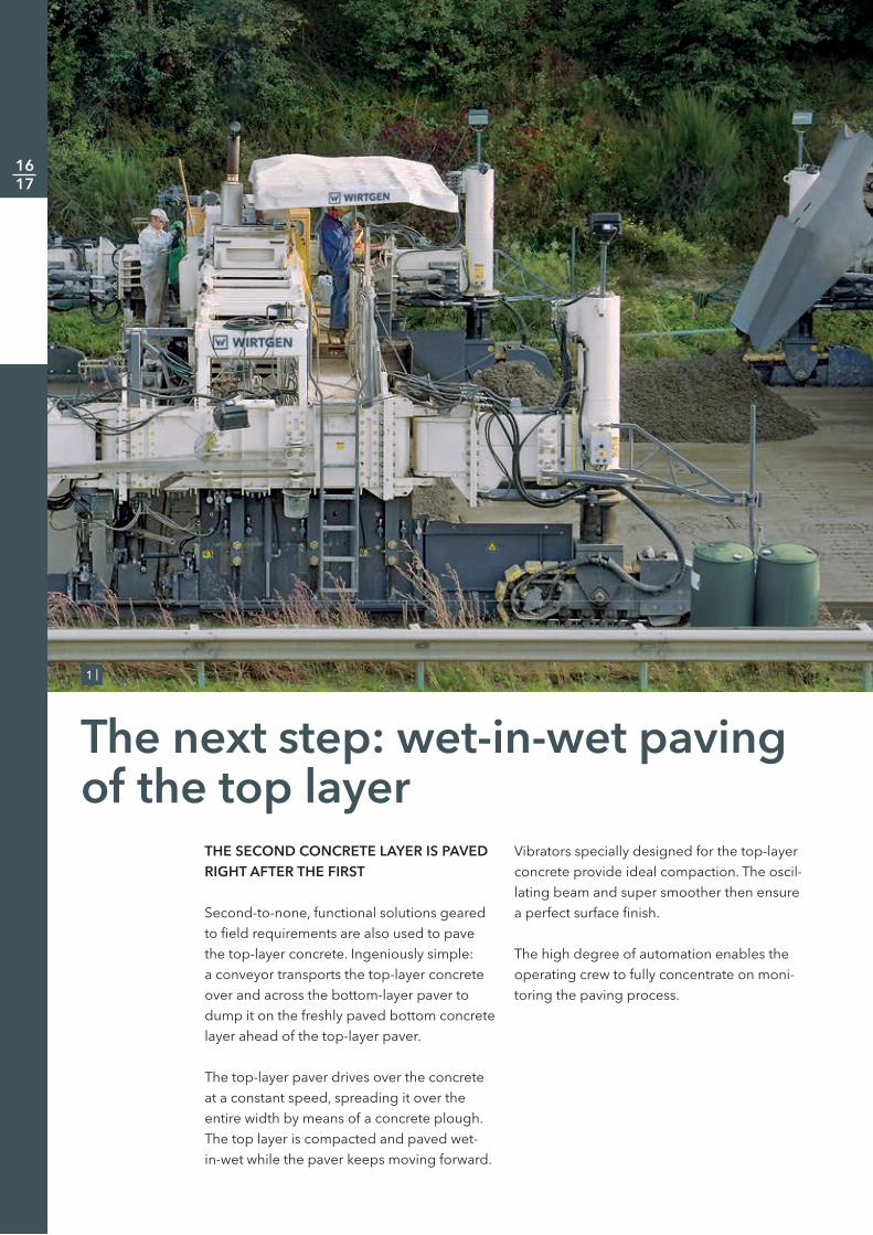
THE SECOND CONCRETE LAYER IS PAVED RIGHT AFTER THE FIRST
Second-to-none, functional solutions geared to field requirements are also used to pave the top-layer concrete. Ingeniously simple: a conveyor transports the top-layer concrete over and across the bottom-layer paver to dump it on the freshly paved bottom concrete layer ahead of the top-layer paver.
The top-layer paver drives over the concrete at a constant speed, spreading it over the entire width by means of a concrete plough. The top layer is compacted and paved wet-in-wet while the paver keeps moving forward.
Vibrators specially designed for the top-layer concrete provide ideal compaction. The oscil-lating beam and super smoother then ensure a perfect surface finish.
The high degree of automation enables the operating crew to fully concentrate on moni-toring the paving process.
The next step: wet-in-wet paving of the top layer
1 |
16 17
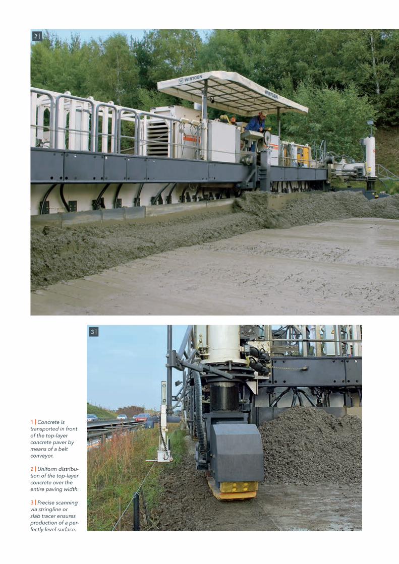
1 | Concrete is transported in front of the top-layer concrete paver by means of a belt conveyor.
2 | Uniform distribu-tion of the top-layer concrete over theentire paving width.
3 | Precise scanning via stringline or slab tracer ensures production of a per-fectly level surface.
2 |
3 |

PERFECT FINISH FOR A PERFECT SURFACE
An ideal surface finish is one factor determin-ing the quality and service life of a pavement. The SP 1500 / SP 1500 L is a cut above in this category as well because it delivers outstand-ing results.
The top-layer concrete is paved wet-in-wet and bonds perfectly with the bottom layer. As the machine continues to travel, the oscil-lating beam and downstream super smoother move over the pavement, with the oscillating
beam oscillating transverse to and the super smoother oscillating in the direction of travel. This combination reliably producesthe specified surface texture.
Dual, hydraulically adjustable sideplates guarantee only minor concrete losses. In addition, the trailing and deep paving moulds designed with a view to the paving thickness produce perfect concrete edges.
Perfection with the finishing touch: automated smoothing
1 |
1 | After super-smoothing, the concrete slab meets all quality requirements.
18 19

3 | The heavy-duty oscillating beam produces an even surface.
4 | Cost-intensive material need onlybe used for the thin top layer.
3 |
4 |
2 |2 | Hydraulically adjustable side-plates ensure clean concrete edges.

From a single supplier: texture curing for optimum results
ENGINEERED RIGHT DOWN TO THE LAST DETAIL
The paving train is equipped with a multi-tude of practical, time-saving features. These include the tried-and-tested texture curing machine which follows right behind the two slipform pavers. To achieve optimum skid resistance of the surface, it applies a burlap or cross broom to the freshly paved concrete.
In a final step, a special liquid is sprayed across the entire width of the concrete pave-ment for effective protection against prema-ture evaporation and cracking. In addition, exposed aggregate concrete surfaces can be produced or longitudinal brooms applied without difficulty.
The operator’s platform of the texture curing machine offers excellent visibility. All controls are arranged in line with ergonomic princi-ples. Extended uptimes are guaranteed by a large storage container for the curing com-pound. The machine’s range of applications is extended further by ancillary equipment, suchas a separate generator or crane.
1 |
20 21

1 | The texture curing machine is used to produce the specified surface texture.
2 | Dispersion is sprayed in a final step to prevent evaporation and cracking.
2 |

22 23
Technical specification SP 1500
*1 = Please consult factory for different offset geometries or special applications*2 = Applicable for the range of dowel bar dimensions specified; for any other dimensions, please consult factory; the dowel bar
inserters will be customized in accordance with pre-selected customer requirements*3 = The range of tie bar dimensions specified above can be covered; for any other dimensions, please consult factory; the longitudinal
joint tie bar and side tie bar inserters will be customized in accordance with pre-selected customer requirements
SP 1500
Range of applications Slab paving
Concrete spreading
Spreading plough for working width 5,000 – 15,250 mm
Slab paving equipment for bottom-layer concrete
Working width 5,000 – 15,250 mm *1
Paving thickness 0 – 400 mm *1
Transverse camber adjustment 0 – 3 %
Dowel bar inserter
Working width 5,000 – 15,250 mm *2
Diameter of dowel bars 25 – 40 mm *2
Dowel bar length 450 – 600 mm *2
Longitudinal joint tie bar inserter
Diameter of tie bars 20 – 40 mm *3
Tie bar length 400 – 1,200 mm *3
Vibration for bottom-layer concrete
Connectors for electric vibration 16, can be extended to 48 (option)
Number of electric vibrators, curved 16, can be extended to 48 (option)
High-frequency generator 80 kVA
Slab paving equipment for top-layer concrete
Working width 5,000 – 15,250 mm *1
Paving thickness 0 – 500 mm *1
Transverse camber adjustment 0 – 3 %
Oscillating beam
Working width 5,000 – 15,250 mm
Super smoother
Working width 5,000 – 15,250 mm
Side tie bar inserter
Diameter of tie bars 20 – 40 mm *3
Tie bar length 400 – 800 mm *3
Vibration for top-layer concrete
Connectors for electric vibration 16, can be extended to 32 (option)
Number of electric T-vibrators 10, can be extended to 32 (option)
High-frequency generator 80 kVA

*4 = Weights depend on the machine’s range of equipment and working width*5 = Weight of machine with half-full water tank, half-full fuel tank, driver (75 kg) and on-board tools
SP 1500
Engine
Engine manufacturer Caterpillar
Type C11 ATAAC
Cooling Water
Number of cylinders 6
Rated power at 2,100 min-1 287 kW / 385 HP / 390 PS
Displacement 11,100 cm3
Fuel consumption, full load 78.7 l / h
Fuel consumption in field mix 35.4 l / h
Emission standards EC Stage 3a / US Tier 3
Electrical system 24 V
Filling capacities
Fuel tank 880 l
Hydraulic fluid tank 420 l
Water tank 870 l
Driving characteristics
Operating speed 0 – 6 m / min
Travel speed 0 – 25 m / min
Track units
Number 4
Steering angle ± 30°
Dimensions (L x W x H) 2,100 x 350 x 715 mm
Height adjustment of machine
Max. hydraulic height adjustment 950 mm
Transport dimensions (L x W x H)
Machine for bottom-layer concrete, working width 15,250 mm 21,500 mm x 3,800 mm x 3,100 mm
Machine for top-layer concrete, working width 15,250 mm 21,500 mm x 3,600 mm x 3,100 mm
Machine weights *4
Operating weight, CE *5 of basic machine including options for bottom-layer concrete, working width 15,250 mm
72,080 kg
Operating weight, CE *5 of basic machine including options for top-layer concrete, working width 15,250 mm
60,520 kg
Transport weight of basic machine including options for bottom-layer concrete, working width 15,250 mm
64,560 kg
Transport weight of basic machine including options for top-layer concrete, working width 15,250 mm
57,620 kg

24 25
Dimensions SP 1500
Slipform paver SP 1500, concrete paving equipment for top-layer concrete, 4-track designDimensions in mm
Working direction
4,04
05,
000
– 15,
250
5,75
0 – 1
6,00
0
6,70
0 – 1
6,95
0
400
850
375
10,040
10,520
8,700
6,570

Slipform paver SP 1500, concrete paving equipment for bottom-layer concrete, 4-track designDimensions in mm
Working direction
9,640
7,510
4,04
0
6,70
0 – 1
6,95
0
5,00
0 – 1
5,25
0
5,75
0 – 1
6,00
0
300
850
375
14,100

26 27
Technical specification SP 1500 L
*1 = Please consult factory for different offset geometries or special applications*2 = Applicable for the range of dowel bar dimensions specified; for any other dimensions, please consult factory; the dowel bar inserters will be customized
in accordance with pre-selected customer requirements*3 = The range of tie bar dimensions specified above can be covered; for any other dimensions, please consult factory; the longitudinal joint tie bar and side
tie bar inserters will be customized in accordance with pre-selected customer requirements
SP 1500 L
Range of applications Slab paving
Concrete spreading
Spreading plough for working width 5,000 – 15,250 mm
Slab paving equipment for bottom-layer concrete
Working width 5,000 – 15,250 mm *1
Paving thickness 0 – 400 mm *1
Transverse camber adjustment 0 – 3 %
Dowel bar inserter
Working width 5,000 – 15,250 mm *2
Diameter of dowel bars 20 – 40 mm *2
Dowel bar length 450 – 600 mm *2
Longitudinal joint tie bar inserter
Diameter of tie bars 20 – 40 mm *3
Tie bar length 400 – 1,200 mm *3
Vibration for bottom-layer concrete
Connectors for electric vibration 16, can be extended to 48 (option)
Number of electric vibrators, curved 16, can be extended to 48 (option)
High-frequency generator 80 kVA
Slab paving equipment for top-layer concrete
Working width 5,000 – 15,250 mm *1
Paving thickness 0 – 500 mm *1
Transverse camber adjustment 0 – 3 %
Oscillating beam
Working width 5,000 – 15,250 mm
Super smoother
Working width 5,000 – 15,250 mm
Side tie bar inserter
Diameter of tie bars 20 – 40 mm *3
Tie bar length 400 – 800 mm *3
Vibration for top-layer concrete
Connectors for electric vibration 16, can be extended to 32 (option)
Number of electric T-vibrators 10, can be extended to 32 (option)
High-frequency generator 80 kVA
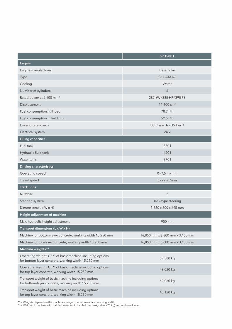
*4 = Weights depend on the machine’s range of equipment and working width*5 = Weight of machine with half-full water tank, half-full fuel tank, driver (75 kg) and on-board tools
SP 1500 L
Engine
Engine manufacturer Caterpillar
Type C11 ATAAC
Cooling Water
Number of cylinders 6
Rated power at 2,100 min-1 287 kW / 385 HP / 390 PS
Displacement 11,100 cm3
Fuel consumption, full load 78.7 l / h
Fuel consumption in field mix 52.5 l / h
Emission standards EC Stage 3a / US Tier 3
Electrical system 24 V
Filling capacities
Fuel tank 880 l
Hydraulic fluid tank 420 l
Water tank 870 l
Driving characteristics
Operating speed 0 – 7,5 m / min
Travel speed 0 – 22 m / min
Track units
Number 2
Steering system Tank-type steering
Dimensions (L x W x H) 3,350 x 300 x 695 mm
Height adjustment of machine
Max. hydraulic height adjustment 950 mm
Transport dimensions (L x W x H)
Machine for bottom-layer concrete, working width 15,250 mm 16,850 mm x 3,800 mm x 3,100 mm
Machine for top-layer concrete, working width 15,250 mm 16,850 mm x 3,600 mm x 3,100 mm
Machine weights *4
Operating weight, CE *5 of basic machine including options for bottom-layer concrete, working width 15,250 mm
59,580 kg
Operating weight, CE *5 of basic machine including options for top-layer concrete, working width 15,250 mm
48,020 kg
Transport weight of basic machine including options for bottom-layer concrete, working width 15,250 mm
52,060 kg
Transport weight of basic machine including options for top-layer concrete, working width 15,250 mm
45,120 kg

28 29
Dimensions SP 1500 L
Working direction
Slipform paver SP 1500 L, concrete paving equipment for top-layer concrete, 2-track designDimensions in mm
4,04
040
0
6,60
0 – 1
6,85
0
5,00
0 – 1
5,25
080
035
0
5,70
0 – 1
5,95
0
7,365
2,460
3,495
5,520
8,400

Working direction
Slipform paver SP 1500 L, concrete paving equipment for bottom-layer concrete, 2-track designDimensions in mm
4,060
5,920
4,04
030
0
13,120
6,60
0 – 1
6,85
0
5,70
0 – 1
5,95
0
5,00
0 – 1
5,25
080
035
0
3,495
2,460
480
30 31
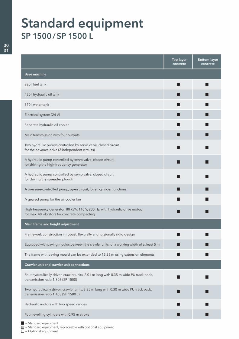
Standard equipmentSP 1500 / SP 1500 L
= Standard equipment = Standard equipment, replaceable with optional equipment = Optional equipment
Top-layer concrete
Bottom-layer concrete
Base machine
880 l fuel tank
420 l hydraulic oil tank
870 l water tank
Electrical system (24 V)
Separate hydraulic oil cooler
Main transmission with four outputs
Two hydraulic pumps controlled by servo valve, closed circuit, for the advance drive (2 independent circuits)
A hydraulic pump controlled by servo valve, closed circuit, for driving the high-frequency generator
A hydraulic pump controlled by servo valve, closed circuit, for driving the spreader plough
A pressure-controlled pump, open circuit, for all cylinder functions
A geared pump for the oil cooler fan
High frequency generator, 80 kVA, 110 V, 200 Hz, with hydraulic drive motor, for max. 48 vibrators for concrete compacting
Main frame and height adjustment
Framework construction in robust, flexurally and torsionally rigid design
Equipped with paving moulds between the crawler units for a working width of at least 5 m
The frame with paving mould can be extended to 15.25 m using extension elements
Crawler unit and crawler unit connections
Four hydraulically driven crawler units, 2.01 m long with 0.35 m wide PU track pads, transmission ratio 1:305 (SP 1500)
Two hydraulically driven crawler units, 3.35 m long with 0.30 m wide PU track pads, transmission ratio 1:403 (SP 1500 L)
Hydraulic motors with two speed ranges
Four levelling cylinders with 0.95 m stroke

Top-layer concrete
Bottom-layer concrete
Machine control and levelling and steering
Digital control system with LCD display which displays all necessary information for the user on a menu and allows parameter settings, e.g. free choice of languages (D / GB / F / E / NL)
Proportional electrohydraulic levelling and steering by PLC system including four (4) levelling sensors, two (2) steering sensors
Sensor mountings, adjustable in height and range
Vibration
10 horizontal T-vibrators, 500 mm –16x bended vibrators (D76), electrically driven, with mechanical height adjustment –Concrete equipment for carriageway paving
Spreader plough with 2 drives
Metering gate and guide
Side header left and right (max. concrete thickness 0.45 m)
Depth paving mould left and right 0.30 m (others on request) –Depth paving mould left and right 0.20 m (others on request) –Oscillating beam 5 m – without crown profile –Super smoother 5 m – 15.25 m –Electrical control DBI / TBI –Automatic dowel bar inserter, base 5 m –Others
Lighting package with 5 halogen headlights 24 V
Paint standard cream white RAL 9001
= Standard equipment = Standard equipment, replaceable with optional equipment = Optional equipment
32 33
= Standard equipment = Standard equipment, replaceable with optional equipment = Optional equipment
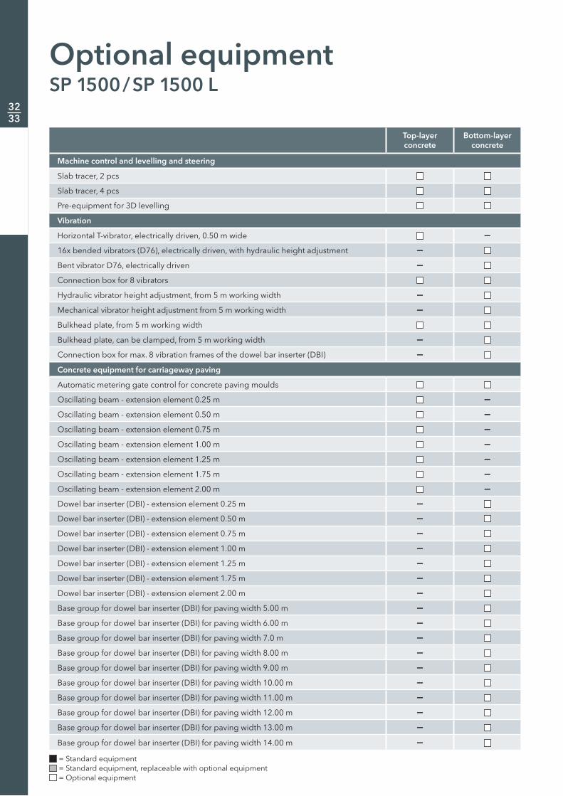
Optional equipmentSP 1500 / SP 1500 L
Top-layer concrete
Bottom-layer concrete
Machine control and levelling and steering
Slab tracer, 2 pcs
Slab tracer, 4 pcs
Pre-equipment for 3D levelling
Vibration
Horizontal T-vibrator, electrically driven, 0.50 m wide –16x bended vibrators (D76), electrically driven, with hydraulic height adjustment –Bent vibrator D76, electrically driven –Connection box for 8 vibrators
Hydraulic vibrator height adjustment, from 5 m working width –Mechanical vibrator height adjustment from 5 m working width –Bulkhead plate, from 5 m working width
Bulkhead plate, can be clamped, from 5 m working width –Connection box for max. 8 vibration frames of the dowel bar inserter (DBI) –Concrete equipment for carriageway paving
Automatic metering gate control for concrete paving moulds
Oscillating beam - extension element 0.25 m –Oscillating beam - extension element 0.50 m –Oscillating beam - extension element 0.75 m –Oscillating beam - extension element 1.00 m –Oscillating beam - extension element 1.25 m –Oscillating beam - extension element 1.75 m –Oscillating beam - extension element 2.00 m –Dowel bar inserter (DBI) - extension element 0.25 m –Dowel bar inserter (DBI) - extension element 0.50 m –Dowel bar inserter (DBI) - extension element 0.75 m –Dowel bar inserter (DBI) - extension element 1.00 m –Dowel bar inserter (DBI) - extension element 1.25 m –Dowel bar inserter (DBI) - extension element 1.75 m –Dowel bar inserter (DBI) - extension element 2.00 m –Base group for dowel bar inserter (DBI) for paving width 5.00 m –Base group for dowel bar inserter (DBI) for paving width 6.00 m –Base group for dowel bar inserter (DBI) for paving width 7.0 m –Base group for dowel bar inserter (DBI) for paving width 8.00 m –Base group for dowel bar inserter (DBI) for paving width 9.00 m –Base group for dowel bar inserter (DBI) for paving width 10.00 m –Base group for dowel bar inserter (DBI) for paving width 11.00 m –Base group for dowel bar inserter (DBI) for paving width 12.00 m –Base group for dowel bar inserter (DBI) for paving width 13.00 m –Base group for dowel bar inserter (DBI) for paving width 14.00 m –
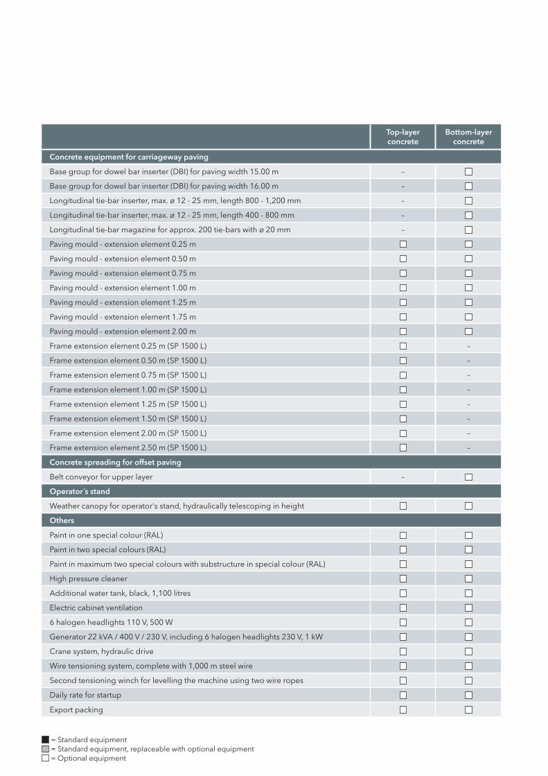
Top-layer concrete
Bottom-layer concrete
Concrete equipment for carriageway paving
Base group for dowel bar inserter (DBI) for paving width 15.00 m –
Base group for dowel bar inserter (DBI) for paving width 16.00 m –
Longitudinal tie-bar inserter, max. ø 12 - 25 mm, length 800 - 1,200 mm –
Longitudinal tie-bar inserter, max. ø 12 - 25 mm, length 400 - 800 mm –
Longitudinal tie-bar magazine for approx. 200 tie-bars with ø 20 mm –
Paving mould - extension element 0.25 m
Paving mould - extension element 0.50 m
Paving mould - extension element 0.75 m
Paving mould - extension element 1.00 m
Paving mould - extension element 1.25 m
Paving mould - extension element 1.75 m
Paving mould - extension element 2.00 m
Frame extension element 0.25 m (SP 1500 L) –
Frame extension element 0.50 m (SP 1500 L) –
Frame extension element 0.75 m (SP 1500 L) –
Frame extension element 1.00 m (SP 1500 L) –
Frame extension element 1.25 m (SP 1500 L) –
Frame extension element 1.50 m (SP 1500 L) –
Frame extension element 2.00 m (SP 1500 L) –
Frame extension element 2.50 m (SP 1500 L) –
Concrete spreading for offset paving
Belt conveyor for upper layer –
Operator´s stand
Weather canopy for operator‘s stand, hydraulically telescoping in height
Others
Paint in one special colour (RAL)
Paint in two special colours (RAL)
Paint in maximum two special colours with substructure in special colour (RAL)
High pressure cleaner
Additional water tank, black, 1,100 litres
Electric cabinet ventilation
6 halogen headlights 110 V, 500 W
Generator 22 kVA / 400 V / 230 V, including 6 halogen headlights 230 V, 1 kW
Crane system, hydraulic drive
Wire tensioning system, complete with 1,000 m steel wire
Second tensioning winch for levelling the machine using two wire ropes
Daily rate for startup
Export packing
= Standard equipment = Standard equipment, replaceable with optional equipment = Optional equipment
34 35


Illustrations and texts are non-binding and may include customized fittings. Subject to technical changes. Performance data depend on operational conditions. No. 2512050 EN-06/16 © by WIRTGEN GmbH 2016. Printed in Germany.
WIRTGEN GmbHReinhard-Wirtgen-Str. 2 · 53578 Windhagen · Germany
Phone: +49 (0) 26 45 / 131-0 · Fax: +49 (0) 26 45 / 131-392Internet: www.wirtgen.com · E-Mail: [email protected]