a six meter moxon antenna - iz3mez six meter moxon... · glass inside both pieces of 5/ 8 inch od...
TRANSCRIPT
April 2004 65
By Allen Baker, KG4JJH
Iwas amazed by the response to my Black Widow antennain the May 2003 QST.1 I subsequently helped quite a fewbuilders locate the hard-to-find fishing pole spreaders and I
also addressed several details about its construction. Many hadnever heard of this antenna configuration and enjoyed buildingit. While the wire version of the Moxon rectangle is a provenperformer, a tubular version provides broader bandwidth andslightly more gain. The two antennas presented here are basedon an article by L.B. Cebik, W4RNL.2 The first is horizontallypolarized for CW and SSB use at the low end of the 6 meterband (50-51 MHz) and the second is vertically polarized for FMuse at the upper portion (52-54 MHz). For ease of reference, Irefer to the first as H-POL and the second as V-POL. All materi-als have been chosen to withstand the elements and are availablelocally or via the Internet for under $100.
The Moxon RectangleI used the program MoxGen3 to generate models at 50.5 and
53.0 MHz, using 5/8 inch OD aluminum tubing. I then fine-tuned them with EZNEC4 to allow for the different tubingsizes. The 6 meter Moxon is built from 5/8 inch OD and1/2 inch OD aluminum tubing with 3/8 inch OD solid aluminumfor the corners. The detailed construction drawings, sheets andEZNEC models for both versions are available at www.arrl.org/files/qst-binaries/6 meter moxon.zip. A basic outline draw-
A 6 Meter Moxon AntennaDiscover 6 meters for the first time or enhance your existing operationwith a rugged but portable version of this novel 2 element antenna.
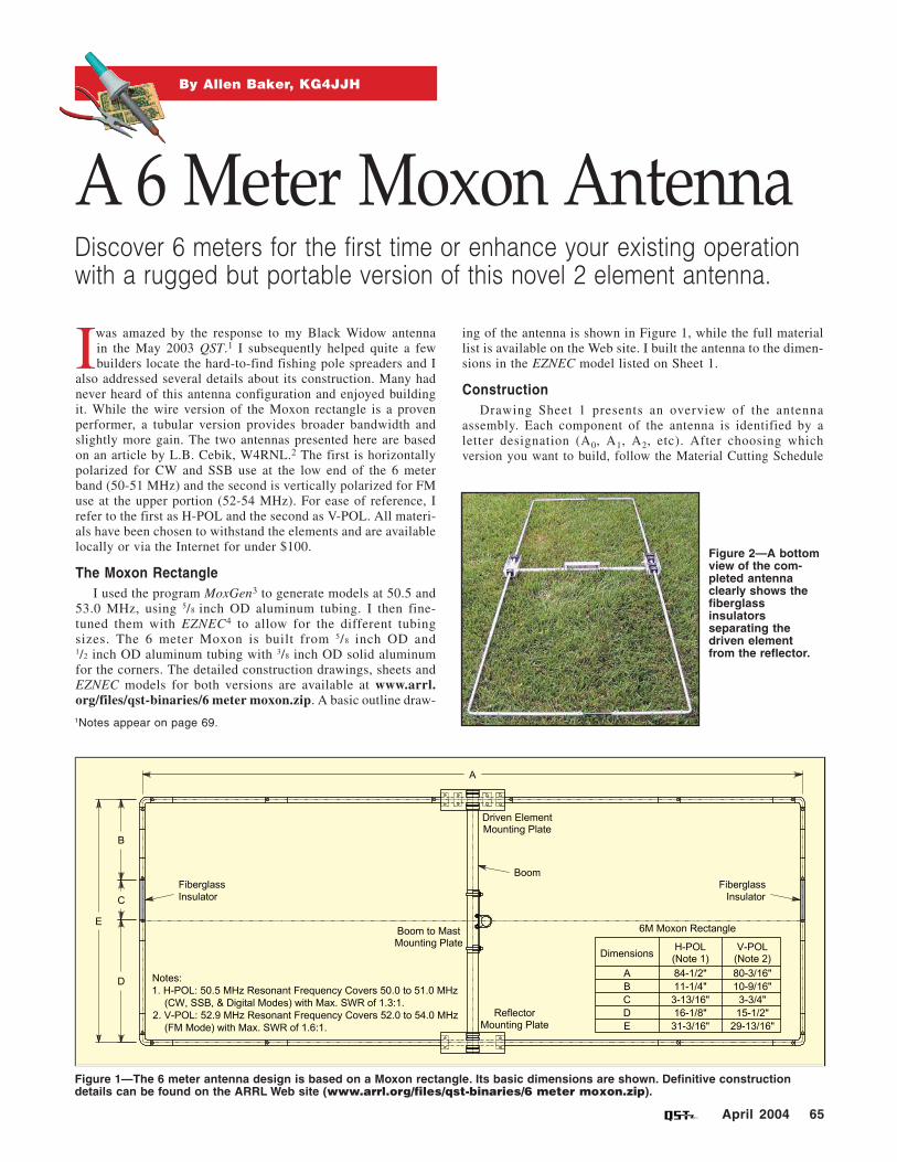
ing of the antenna is shown in Figure 1, while the full materiallist is available on the Web site. I built the antenna to the dimen-sions in the EZNEC model listed on Sheet 1.
ConstructionDrawing Sheet 1 presents an overview of the antenna
assembly. Each component of the antenna is identified by aletter designation (A0, A1, A2, etc). After choosing whichversion you want to build, follow the Material Cutting Schedule
1Notes appear on page 69.
Figure 1—The 6 meter antenna design is based on a Moxon rectangle. Its basic dimensions are shown. Definitive constructiondetails can be found on the ARRL Web site (www.arrl.org/files/qst-binaries/6 meter moxon.zip).
Figure 2—A bottomview of the com-pleted antennaclearly shows thefiberglassinsulatorsseparating thedriven elementfrom the reflector.
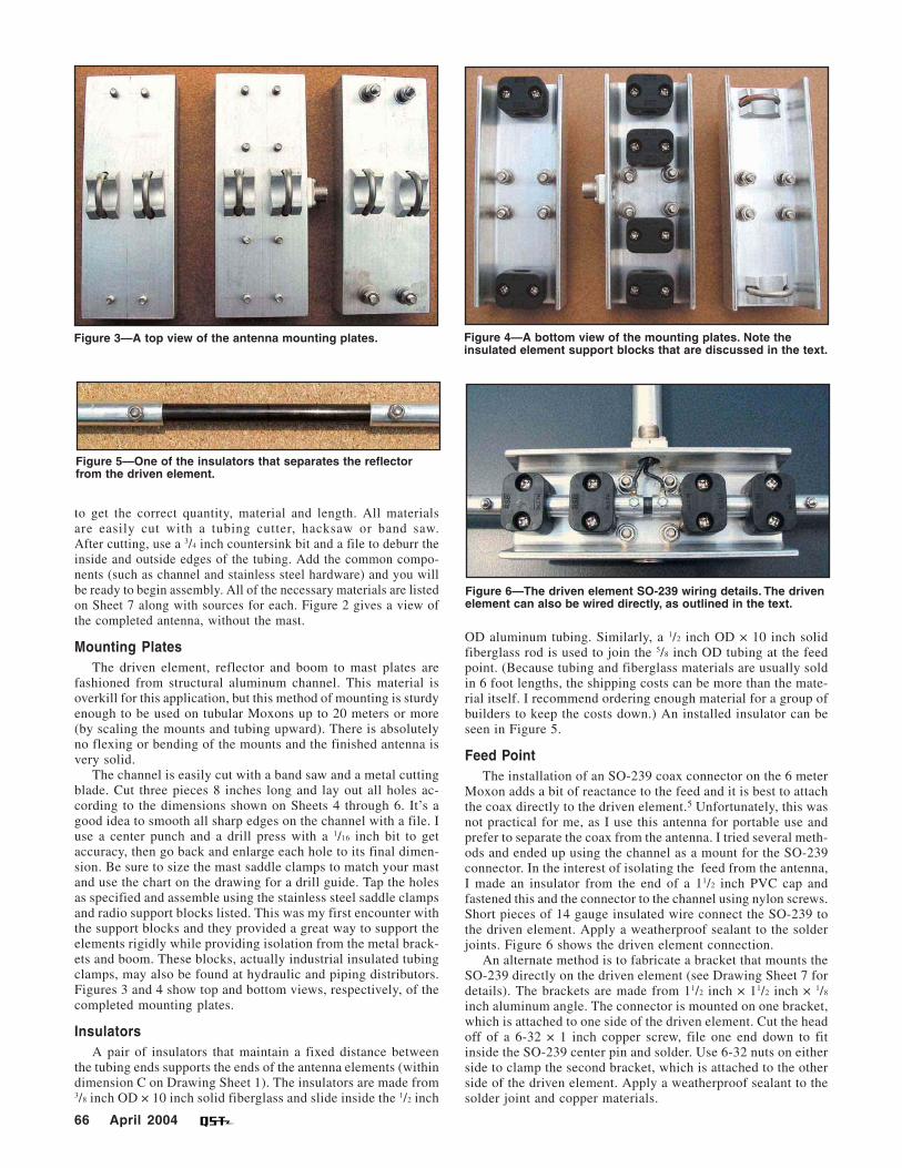
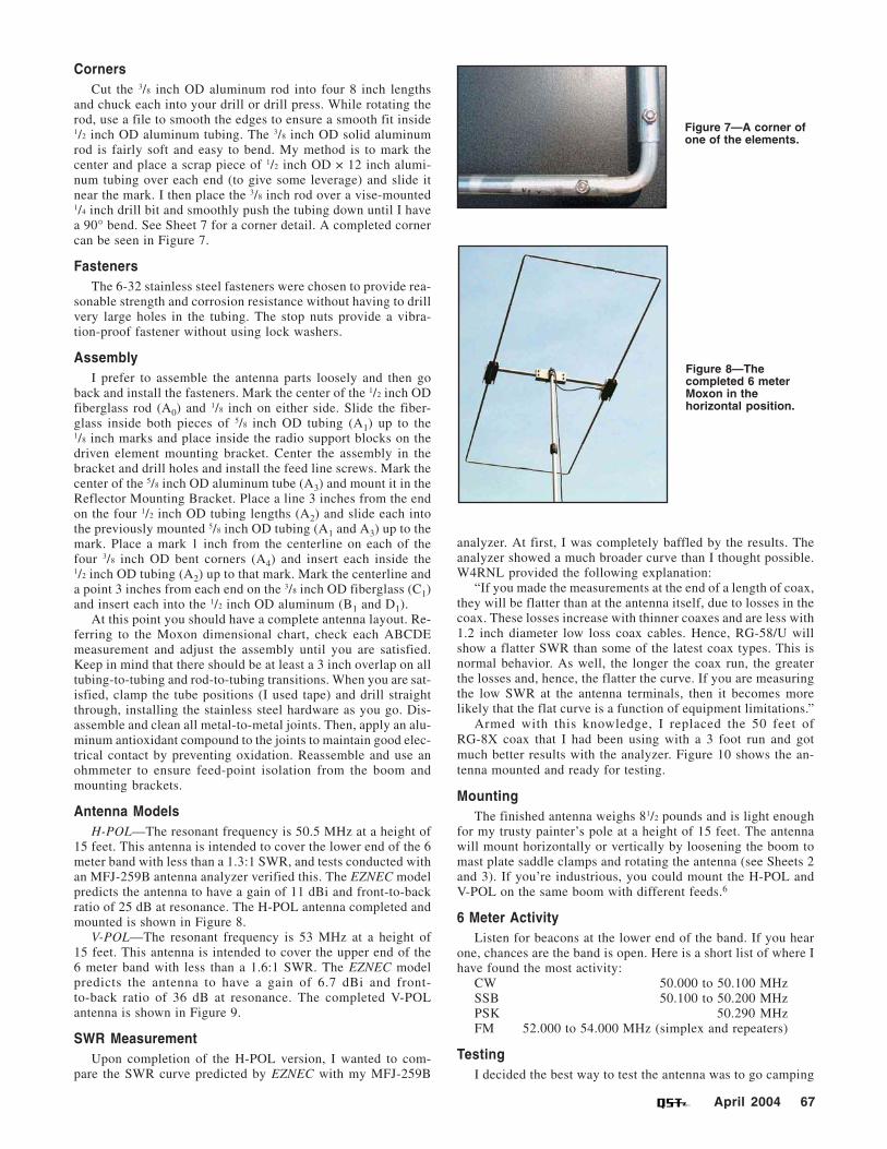
Figure 3—A top view of the antenna mounting plates.
Figure 5—One of the insulators that separates the reflector from the driven element.
to get the correct quantity, material and length. All materials are easily cut with a tubing cutter, hacksaw or band saw. After cutting, use a 3/4 inch countersink bit and a file to deburr the inside and outside edges of the tubing. Add the common compo-nents (such as channel and stainless steel hardware) and you will be ready to begin assembly. All of the necessary materials are listed on Sheet 7 along with sources for each. Figure 2 gives a view of the completed antenna, without the mast.
Mounting Plates The driven element, reflector and boom to mast plates are
fashioned from structural aluminum channel. This material is overkill for this application, but this method of mounting is sturdy enough to be used on tubular Moxons up to 20 meters or more (by scaling the mounts and tubing upward). There is absolutely no flexing or bending of the mounts and the finished antenna is very solid.
The channel is easily cut with a band saw and a metal cutting blade. Cut three pieces 8 inches long and lay out all holes ac-cording to the dimensions shown on Sheets 4 through 6. It’s a good idea to smooth all sharp edges on the channel with a file. I use a center punch and a drill press with a 1/16 inch bit to get accuracy, then go back and enlarge each hole to its final dimen-sion. Be sure to size the mast saddle clamps to match your mast and use the chart on the drawing for a drill guide. Tap the holes as specified and assemble using the stainless steel saddle clamps and radio support blocks listed. This was my first encounter with the support blocks and they provided a great way to support the elements rigidly while providing isolation from the metal brack-ets and boom. These blocks, actually industrial insulated tubing clamps, may also be found at hydraulic and piping distributors. Figures 3 and 4 show top and bottom views, respectively, of the completed mounting plates.
Insulators A pair of insulators that maintain a fixed distance between
the tubing ends supports the ends of the antenna elements (within dimension C on Drawing Sheet 1). The insulators are made from 3/8 inch OD × 10 inch solid fiberglass and slide inside the 1/2 inch
66 April 2004
Figure 4—A bottom view of the mounting plates. Note the insulated element support blocks that are discussed in the text.
Figure 6—The driven element SO-239 wiring details. The driven element can also be wired directly, as outlined in the text.
OD aluminum tubing. Similarly, a 1/2 inch OD × 10 inch solid fiberglass rod is used to join the 5/8 inch OD tubing at the feed point. (Because tubing and fiberglass materials are usually sold in 6 foot lengths, the shipping costs can be more than the mate-rial itself. I recommend ordering enough material for a group of builders to keep the costs down.) An installed insulator can be seen in Figure 5.
Feed Point The installation of an SO-239 coax connector on the 6 meter
Moxon adds a bit of reactance to the feed and it is best to attach the coax directly to the driven element.5 Unfortunately, this was not practical for me, as I use this antenna for portable use and prefer to separate the coax from the antenna. I tried several meth-ods and ended up using the channel as a mount for the SO-239 connector. In the interest of isolating the feed from the antenna, I made an insulator from the end of a 11/2 inch PVC cap and fastened this and the connector to the channel using nylon screws. Short pieces of 14 gauge insulated wire connect the SO-239 to the driven element. Apply a weatherproof sealant to the solder joints. Figure 6 shows the driven element connection.
An alternate method is to fabricate a bracket that mounts the SO-239 directly on the driven element (see Drawing Sheet 7 for details). The brackets are made from 11/2 inch × 11/2 inch × 1/8
inch aluminum angle. The connector is mounted on one bracket, which is attached to one side of the driven element. Cut the head off of a 6-32 × 1 inch copper screw, file one end down to fit inside the SO-239 center pin and solder. Use 6-32 nuts on either side to clamp the second bracket, which is attached to the other side of the driven element. Apply a weatherproof sealant to the solder joint and copper materials.
Corners Cut the 3/8 inch OD aluminum rod into four 8 inch lengths
and chuck each into your drill or drill press. While rotating the rod, use a file to smooth the edges to ensure a smooth fit inside 1/2 inch OD aluminum tubing. The 3/8 inch OD solid aluminum rod is fairly soft and easy to bend. My method is to mark the center and place a scrap piece of 1/2 inch OD × 12 inch alumi-num tubing over each end (to give some leverage) and slide it near the mark. I then place the 3/8 inch rod over a vise-mounted 1/4 inch drill bit and smoothly push the tubing down until I have a 90° bend. See Sheet 7 for a corner detail. A completed corner can be seen in Figure 7.
Fasteners The 6-32 stainless steel fasteners were chosen to provide rea-
sonable strength and corrosion resistance without having to drill very large holes in the tubing. The stop nuts provide a vibra-tion-proof fastener without using lock washers.
Assembly I prefer to assemble the antenna parts loosely and then go
back and install the fasteners. Mark the center of the 1/2 inch OD fiberglass rod (A0) and 1/8 inch on either side. Slide the fiber-glass inside both pieces of 5/8 inch OD tubing (A1) up to the 1/8 inch marks and place inside the radio support blocks on the driven element mounting bracket. Center the assembly in the bracket and drill holes and install the feed line screws. Mark the center of the 5/8 inch OD aluminum tube (A3) and mount it in the Reflector Mounting Bracket. Place a line 3 inches from the end on the four 1/2 inch OD tubing lengths (A2) and slide each into the previously mounted 5/8 inch OD tubing (A1 and A3) up to the mark. Place a mark 1 inch from the centerline on each of the four 3/8 inch OD bent corners (A4) and insert each inside the 1/2 inch OD tubing (A2) up to that mark. Mark the centerline and a point 3 inches from each end on the 3/8 inch OD fiberglass (C1) and insert each into the 1/2 inch OD aluminum (B1 and D1).
At this point you should have a complete antenna layout. Re-ferring to the Moxon dimensional chart, check each ABCDE measurement and adjust the assembly until you are satisfied. Keep in mind that there should be at least a 3 inch overlap on all tubing-to-tubing and rod-to-tubing transitions. When you are sat-isfied, clamp the tube positions (I used tape) and drill straight through, installing the stainless steel hardware as you go. Dis-assemble and clean all metal-to-metal joints. Then, apply an alu-minum antioxidant compound to the joints to maintain good elec-trical contact by preventing oxidation. Reassemble and use an ohmmeter to ensure feed-point isolation from the boom and mounting brackets.
Antenna Models H-POL—The resonant frequency is 50.5 MHz at a height of
15 feet. This antenna is intended to cover the lower end of the 6 meter band with less than a 1.3:1 SWR, and tests conducted with an MFJ-259B antenna analyzer verified this. The EZNEC model predicts the antenna to have a gain of 11 dBi and front-to-back ratio of 25 dB at resonance. The H-POL antenna completed and mounted is shown in Figure 8.
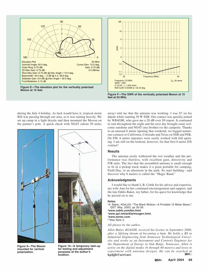
V-POL—The resonant frequency is 53 MHz at a height of 15 feet. This antenna is intended to cover the upper end of the 6 meter band with less than a 1.6:1 SWR. The EZNEC model predicts the antenna to have a gain of 6.7 dBi and front-to-back ratio of 36 dB at resonance. The completed V-POL antenna is shown in Figure 9.
SWR Measurement Upon completion of the H-POL version, I wanted to com-
pare the SWR curve predicted by EZNEC with my MFJ-259B
Figure 7—A corner of one of the elements.
Figure 8—The completed 6 meter Moxon in the horizontal position.
analyzer. At first, I was completely baffled by the results. The analyzer showed a much broader curve than I thought possible. W4RNL provided the following explanation:
“If you made the measurements at the end of a length of coax, they will be flatter than at the antenna itself, due to losses in the coax. These losses increase with thinner coaxes and are less with 1.2 inch diameter low loss coax cables. Hence, RG-58/U will show a flatter SWR than some of the latest coax types. This is normal behavior. As well, the longer the coax run, the greater the losses and, hence, the flatter the curve. If you are measuring the low SWR at the antenna terminals, then it becomes more likely that the flat curve is a function of equipment limitations.”
Armed with this knowledge, I replaced the 50 feet of RG-8X coax that I had been using with a 3 foot run and got much better results with the analyzer. Figure 10 shows the an-tenna mounted and ready for testing.
Mounting The finished antenna weighs 81/2 pounds and is light enough
for my trusty painter’s pole at a height of 15 feet. The antenna will mount horizontally or vertically by loosening the boom to mast plate saddle clamps and rotating the antenna (see Sheets 2 and 3). If you’re industrious, you could mount the H-POL and V-POL on the same boom with different feeds.6
6 Meter Activity Listen for beacons at the lower end of the band. If you hear
one, chances are the band is open. Here is a short list of where I have found the most activity:
CW 50.000 to 50.100 MHz SSB 50.100 to 50.200 MHz PSK 50.290 MHz FM 52.000 to 54.000 MHz (simplex and repeaters)
Testing I decided the best way to test the antenna was to go camping
April 2004 67

68 April 2004
Antenna Patterns and SWR PlotsHere are the both azimuth and elevation antenna
patterns for the 6 meter Moxon antenna, including theSWR plots. These are presented for both the verticallyand horizontally polarized antennas and were madeat a modeled test height of 15 feet. All of the plots
were made using EZNEC software.EZNEC predicts a gain of 11.06 dBi for the horizontally
polarized Moxon and the constructed antenna appearsto verify that model. The SWR has, likewise, beenconfirmed.
Figure A—The 6 meter horizontally polarized Moxon azimuthplot at 15 feet.
Figure B—The elevation plot for the horizontally polarizedMoxon at 15 feet.
Figure C—The SWR of the horizontally polarized Moxon at 15feet at 50.5 MHz.
Figure D—The 6 meter vertically polarized Moxon azimuthplot at 15 feet.
April 2004 69
Figure E—The elevation plot for the vertically polarizedMoxon at 15 feet.
Figure 10—A temporary lash-upfor testing and adjustmentpurposes at the author’slocation.
Figure 9—The Moxonmounted for verticalpolarization.
during the July 4 holiday. As luck would have it, tropical stormBill was passing through our area, so it was raining heavily. Weset up camp in a light drizzle and then mounted the Moxon onthe painter’s pole. A quick check with NG4T (about 50 miles
away) told me that the antenna was working. I was S7 on hisdipole while running 30 W SSB. Our contact was quickly joinedby WB4GBI, who gave me a 20 dB over S9 report. It continuedto rain throughout the night and the next day brought some wel-come sunshine and NG4T (my brother) to the campsite. Thanksto an unusual 6 meter opening that weekend, we logged numer-ous contacts to California, Colorado and Texas on SSB and PSK.On FM, 6 meter repeaters were easily worked with full quiet-ing. I am still on the lookout, however, for that first 6 meter DXcontact!
ResultsThe antenna easily withstood the wet weather and the per-
formance was flawless, with excellent gain, directivity andF/B ratio. The fact that the assembled antenna is small enoughto fit in a pickup truck makes it a great portable for camping,Field Day, or an afternoon in the park. So start building—anddiscover why 6 meters is called the “Magic Band.”
AcknowledgmentsI would like to thank L.B. Cebik for his advice and expertise,
my wife Ann for her continued encouragement and support, andthe late Oddis Baker, my father, for his quest for knowledge thathe passed on to me.
Notes1A. Baker, KG4JJH, “The Black Widow—A Portable 15 Meter Beam,”
QST, May, 2003, pp 35-39.2www.cebik.com/6m.html.3www.qsl.net/ac6la/moxgen.html.4www.eznec.com.5,6See Note 2.
All photos by the author.
Allen Baker, KG4JJH, received his license in September 2000,after a lifelong dream of becoming a ham. He holds a BS inIndustrial Engineering from Tennessee Technological Univer-sity and works as an Instrument and Controls Engineer forthe Department of Energy in Oak Ridge, Tennessee. Allen isactive on the digital modes (6 through 40 meters) and loves toexperiment with antenna designs. He can be reached [email protected].
Figure F—The SWR of the vertically polarized Moxon at 15feet at 53 MHz.