a simple two-stage co single stage, compound, cascade and … stage... · 2018-05-03 · a compound...
TRANSCRIPT

11
By Ramesh ParanjpeyFellow ASHRAE Life Member, Pune
A simple two-stage CO2 booster system (Courtesy: Emerson)
About the AuthorRamesh Paranjpey is a mechanical engineer with an M. Tech. in refrigeration from IIT Bombay, having over 35 years’ experience. He has worked in very senior positions with Kirloskar Pneumatic in Pune, Carrier Transicold in Bangalore and Singapore and Voltas-Air International in Pune. Presently, he works for himself as a technical advisor and consultant. He is an ASHRAE Fellow, past president ASHRAE W.I. Chapter and past president ISHRAE Pune Chapter. He can be contacted at [email protected]
Single Stage, Compound,
Cascade and Booster
Systems and Inter-
stage Cooling Methods
IntroductionThis article discusses various refrigeration systems and
differences between:a. Single stage, two stage and cascade systems, b. Single frame two stage compressor inter-stage cooling
systems, c. Various methods of inter-stage gas cooling, their advantages
and drawbacks, and d. Performance comparisons of various methods.
Compressor and Compression RatioFirst, we need to understand the function of a compressor in a
closed cycle refrigeration system.The function of a compressor in a vapour compression
refrigeration system is to draw the low temperature low pressure saturated or superheated vapour from the evaporator and raise its energy level so that it is able to reject heat to the cooling medium, either initially to water and then to the atmosphere, or directly to the atmosphere in an air cooled system.
Since heat always flows from high temperature to low temperature, it is necessary to raise the energy level of the refrigerant beyond the condenser cooling water temperature in case of water cooled systems or air temperature in case of air cooled systems for rejecting heat.
The compressor performs this function of raising the energy level and is the most important part in the refrigeration system, as it is the only moving component in the system and is also the most expensive equipment. The compressor therefore needs to be protected since any fault anywhere in the system finally results in malfunction or breakdown of the compressor.
The problems that cause compressor malfunction or breakdown are generally:1. System contamination caused by dirt, dust or other material
coming from the internals of piping, e.g. welding material.2. Liquid reaching the compressor due to faulty plant design,
installation or operation.3. High operating temperatures beyond allowable limits;
these conditions could be due to high superheat of gas at compressor entry, non-condensable gases, high discharge pressures, high compression ratio, etc.
Cold Chain d March 2018 C11

12
Compression ratio is the ratio between absolute discharge pressure and absolute suction pressure.
As the evaporator temperature and pressure decrease, compression ratio increases and therefore the discharge temperature goes up.
While designing Industrial Refrigeration systems, especially for low temperature applications using ammonia as the refrigerant, many times we come across a system where the compression ratio exceeds 10 to 12 and it is then obvious that a two-stage system would be a better choice than a single stage system. The manufacturer’s capacity charts also prohibit use of compressors beyond a certain difference between saturated condensing temperature (SCT) and saturated suction temperature (SST) and not saturated evaporating temperature (SET).High compression ratio causes:1. Loss of efficiency.2. High discharge temperatures.3. Carbonization of oil and reduced viscosity, affecting lubrication.4. Damage due to high bearing loads.5. Excessive wear.
Table 1 shows isentropic discharge temperatures for various refrigerants currently used in a typical low temperature application, say at -20°C evaporating and +40°C condensing temperature.Table 1: Isentropic discharge temperatures for refrigerants used in a
typical low temperature application
Refrigerant Cp/Cv at boiling point or at atmospheric pressure
Approximate isentropic discharge temperature, °C
R22 1.236 75
R134a 1.154 55
R404A 1.166 58
R410A 1.244 70
R717 (ammonia) 1.348 145
Where,Cp is specific heat at constant pressure,Cv is specific heat at constant volume,Cp/Cv is known as index of compression and generally
represented as ‘γ’.As can be seen from Table 1, for similar operating compression
ratio, ammonia compressors will have higher discharge gas temperatures compared to other refrigerants.
The maximum allowable discharge gas temperature is 130-140°C with use of mineral oils for compressor lubrication. If the isentropic temperature exceeds this limit, it is always advisable to go for multi-staging. As a thumb rule, if the allowable temperature difference between SCT and SST is more than 50°C for ammonia and 70°C for R22 and other refrigerants, it is advisable to design two-stage systems.
Many compressor manufacturers also indicate in their published ratings the allowable difference between saturated discharge and suction temperatures, thus limiting the use of single stage compressors.
Since low temperature applications require high compression ratios, they are accomplished by carrying out compression in two or more stages. The discharge from the first compression stage becomes the suction of next stage after the superheat of the gas is reduced.
Single and Two-stage CompressionThe simplest way to explain the difference between a single
stage compressor and dual or two-stage compressor is the number of times that the refrigerant is compressed. In a single stage system, the refrigerant is compressed once and in a two-stage system the refrigerant is compressed twice.
In a single stage reciprocating compressor the refrigerant is drawn into a cylinder and compressed in a single piston stroke, and then the refrigerant goes to the condenser as shown in Figure 1.
A system with multiple compressors running in parallel without any inter-stage cooling is considered as single compression, not as a compound or two-stage system.Compound Refrigeration System
A compound system uses two or more compressors – reciprocating, screw or centrifugal – in series using a single refrigerant.
The system could be two-stage, three-stage or even more, depending upon the application and low temperature required to be achieved.
A compound system must therefore include additional components such as intercooler, economizer or sub-cooler to improve the system efficiency. A two-stage system is in fact a compound system having a combination of two single stage systems with an intermediate intercooler.
In two-stage compression, the first step is the same except that the refrigerant from the low stage is not directed to the condenser; it is sent via an intercooler. The discharge gas superheat is then reduced and the saturated or slightly superheated gas goes to second high stage suction and is compressed again before going to the condenser. The final discharge gas temperature is therefore much lower than if compression had taken place in single stage, as shown in Figure 2.
Figure 1: Single stage compression
Single Stage, Compound, Cascade and Booster Systems and Inter-stage Cooling Methods
C12 Cold Chain d March 2018

13
Two-stage OperationIf the compression ratio tends to go beyond 8 to 10, many
times it is found that a two-stage system operation is much more economical, consumes lower power and leads to overall lower compressor displacement and lower discharge temperatures.
A two-stage operation uses the same refrigerant for high and low stages, and the inter-stage cooling of the low stage gas is achieved by various designs leading to its de-superheating before it goes to the high stage suction. This ensures lower intermediate and final discharge gas temperatures.
A two-stage system can be with two different compressors or with an inbuilt single frame compressor in which the cylinders are arranged in such a manner that some cylinders operate as the high stage and the remaining cylinders operate as the low stage.Advantages of Two-stage Systems • Increase in the refrigeration effect. • Removal of flash gas in the inter-stage cooler. • Reduced discharge gas temperature. • Reduced equipment size. • Reduced system power consumption. • Reduced annual operation expenses.
Normally a two-stage system operates most efficiently when the pressure ratio for the low stage and the high stage is equal or, in other words, intermediate pressure is a square root of the overall compression ratio; Pi = √Pc x Po. This is the ideal intermediate pressure and saturated temperature and is possible when the number of high stage cylinders is half the number of low stage cylinders. For example, a 6-cylinder compressor with four low stage and two high stage cylinders has higher efficiency compared to five low stage and one high stage cylinder arrangement; however, one can achieve much lower evaporating temperatures easily with the second arrangement.
If two separate compressors are used, the application engineer can select the proper intermediate pressure; however, if he is using uni-built single frame design of a compressor, the selection of intermediate pressure depends upon the cylinder ratio of high and low stages for the particular compressor model.
Inter-stage CoolingFour inter-stage gas cooling methods are normally used for
two-stage application. These are: A. Direct injection of liquid for gas cooling in the inter-stage
system. B. Direct injection with inter-stage gas and liquid cooler
system. C. Open type flash cooler system. D. Closed flash type inter-stage cooler system.
We shall now discuss each of these methods in greater details and their advantages as well as disadvantages.System A: Direct Injection of Liquid for Gas Cooling in the Inter-stage
Figure 2: Two-stage compression
Figure 3: Direct injection of liquid for gas cooling in the inter-stage
LegendTSC : Two stage compressor Qo : Compressor capacityIC : Injection inter-stage cooler Pe : Compressor shaft powerTXV : Thermostatic expansion valve n : Maximum rotational speedOS :Oilseparator ∆tc :Liquidsub-coolingCD :Condenser ∆tm :HPsuctionsuperheatTVE :Throttlevalveforfeedingevaporator ∆to :LPsuctionsuperheatEV : Evaporator Pc : Saturated condensing pressuretc : Saturated condensing temperature Pm : Saturated intermediate pressuretm : Saturated intermediate temperature Po : Saturated evaporating pressureto : Saturated evaporating temperature h : Enthalpy
Cold Chain d March 2018 C13
14
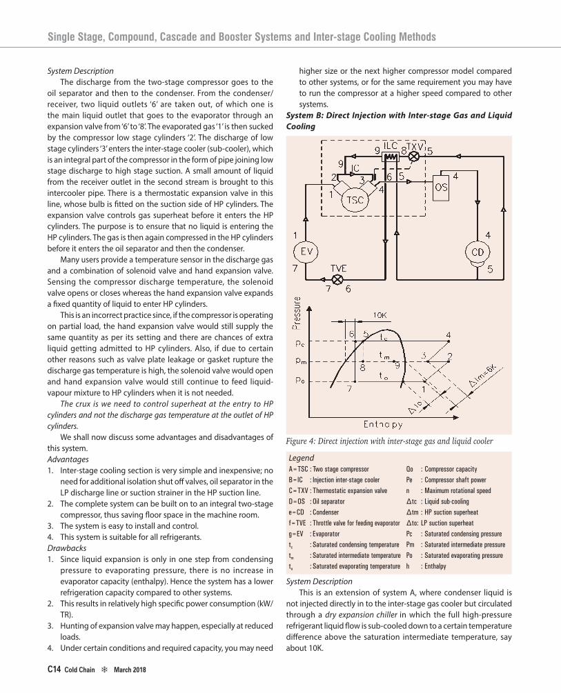
System DescriptionThe discharge from the two-stage compressor goes to the
oil separator and then to the condenser. From the condenser/receiver, two liquid outlets ‘6’ are taken out, of which one is the main liquid outlet that goes to the evaporator through an expansion valve from ‘6’ to ‘8’. The evaporated gas ‘1’ is then sucked by the compressor low stage cylinders ‘2’. The discharge of low stage cylinders ‘3’ enters the inter-stage cooler (sub-cooler), which is an integral part of the compressor in the form of pipe joining low stage discharge to high stage suction. A small amount of liquid from the receiver outlet in the second stream is brought to this intercooler pipe. There is a thermostatic expansion valve in this line, whose bulb is fitted on the suction side of HP cylinders. The expansion valve controls gas superheat before it enters the HP cylinders. The purpose is to ensure that no liquid is entering the HP cylinders. The gas is then again compressed in the HP cylinders before it enters the oil separator and then the condenser.
Many users provide a temperature sensor in the discharge gas and a combination of solenoid valve and hand expansion valve. Sensing the compressor discharge temperature, the solenoid valve opens or closes whereas the hand expansion valve expands a fixed quantity of liquid to enter HP cylinders.
This is an incorrect practice since, if the compressor is operating on partial load, the hand expansion valve would still supply the same quantity as per its setting and there are chances of extra liquid getting admitted to HP cylinders. Also, if due to certain other reasons such as valve plate leakage or gasket rupture the discharge gas temperature is high, the solenoid valve would open and hand expansion valve would still continue to feed liquid-vapour mixture to HP cylinders when it is not needed.
The crux is we need to control superheat at the entry to HP cylinders and not the discharge gas temperature at the outlet of HP cylinders.
We shall now discuss some advantages and disadvantages of this system.Advantages1. Inter-stage cooling section is very simple and inexpensive; no
need for additional isolation shut off valves, oil separator in the LP discharge line or suction strainer in the HP suction line.
2. The complete system can be built on to an integral two-stage compressor, thus saving floor space in the machine room.
3. The system is easy to install and control.4. This system is suitable for all refrigerants.Drawbacks1. Since liquid expansion is only in one step from condensing
pressure to evaporating pressure, there is no increase in evaporator capacity (enthalpy). Hence the system has a lower refrigeration capacity compared to other systems.
2. This results in relatively high specific power consumption (kW/TR).
3. Hunting of expansion valve may happen, especially at reduced loads.
4. Under certain conditions and required capacity, you may need
higher size or the next higher compressor model compared to other systems, or for the same requirement you may have to run the compressor at a higher speed compared to other systems.
System B: Direct Injection with Inter-stage Gas and Liquid Cooling
Figure 4: Direct injection with inter-stage gas and liquid cooler
LegendA=TSC : Two stage compressor Qo : Compressor capacityB=IC : Injection inter-stage cooler Pe : Compressor shaft powerC=TXV : Thermostatic expansion valve n : Maximum rotational speedD=OS :Oilseparator ∆tc :Liquidsub-coolinge=CD :Condenser ∆tm :HPsuctionsuperheatf=TVE : Throttle valve for feeding evaporator ∆to: LPsuctionsuperheatg=EV : Evaporator Pc : Saturated condensing pressuretc : Saturated condensing temperature Pm : Saturated intermediate pressuretm : Saturated intermediate temperature Po : Saturated evaporating pressureto : Saturated evaporating temperature h : Enthalpy
System DescriptionThis is an extension of system A, where condenser liquid is
not injected directly in to the inter-stage gas cooler but circulated through a dry expansion chiller in which the full high-pressure refrigerant liquid flow is sub-cooled down to a certain temperature difference above the saturation intermediate temperature, say about 10K.
Single Stage, Compound, Cascade and Booster Systems and Inter-stage Cooling Methods
C14 Cold Chain d March 2018

15
Advantages1. Thermodynamically identical alternative as for system D.2. It has the same favorable refrigeration capacity and power
consumption, but much smaller liquid content of inter-stage cooler and trouble free oil return to HP cylinders.
3. Inter-stage cooling section is smaller, simpler, less expensive and more convenient than system D.
4. It can be built on the compressor like system A, resulting in saving of space.
5. As with system A, no LP oil separator, HP suction strainer or isolation valves between stages are required.
Drawbacks1. Hunting of expansion valve may happen at reduced loads.2. This system is more suitable for R22 and R404A applications
and is seldom used in ammonia applications.System C: Open Flash Inter-stage Cooling
System DescriptionInter-stage cooling takes place by passing the full hot
discharge gas from LP cylinders through a liquid ammonia refrigerant inside the vessel, called open flash cooler. The gas gets condensed and reaches intermediate pressure. This is achieved by passing full liquid refrigerant flow from the high-pressure condenser and expanding it through a throttle valve to intermediate pressure. Both the gas from low stage and the expanded liquid/flash gas from high stage mix and the mixture reaches equilibrium at intermediate pressure.
The saturated liquid from this intermediate vessel is then further expanded through a throttle valve to the required temperature and pressure and fed to the evaporator either directly or through LP vessel if it is a force-feed ammonia pump circulation system.
An important point to be kept in mind while using open flash cooler is that the mass flow rates in lower stage and higher stage are different. The high stage will have more refrigerant mass flow rate since it has to absorb heat equal to refrigeration load plus heat of compression of low stage. This does not mean that more swept volume is required in high stage. In fact, much lower swept volume is required since the density of gas is higher at intermediate pressure and temperature compared to low stage suction conditions.Advantages1. The refrigeration effect is higher compared to all other
systems for the given operating conditions. (The enthalpy difference is the maximum.)
2. This results in minimum power consumption for the required refrigeration effect.
3. C.O.P is the highest or kW/TR is the lowest.4. This results in minimum operating cost, especially where
the running time per year is very high.5. This results in less refrigerant mass flow and thus needs a
smaller compressor or the same compressor at lower RPM.Drawbacks1. Inter-stage cooling section is complicated and expensive
due to the necessity of shut off valve, additional oil separator in the LP discharge line and a suction strainer in HP suction line.
2. It requires automatic capacity control to load and unload cylinders as per variation in load and suction pressure.
3. An expensive set of level controls are required for intermediate pressure vessels and extra safety valve, drain valve and purge valve are needed.
4. It requires extra floor space in the machine room to accommodate inter-stage cooler and its controls.
5. Installation is less convenient since the intermediate vessel is required to be located above LP vessel in case of ammonia pump circulation systems as the pressure difference across the throttle control valve is low and many times liquid feeding in evaporators/LP vessels becomes a problem if sufficient care is not taken to ensure minimum
Figure 5: Open type flash cooler system
LegendA=TSC : Two stage compressor Qo : Compressor capacityB=IC : Injection inter-stage cooler Pe : Compressor shaft powerC=TXV : Thermostatic expansion valve n : Maximum rotational speedD=OS :Oilseparator ∆tc :Liquidsub-coolinge=CD :Condenser ∆tm :HPsuctionsuperheatf=TVE :Throttlevalveforfeedingevaporator ∆to :LPsuctionsuperheatg=EV : Evaporator Pc : Saturated condensing pressuretc : Saturated condensing temperature Pm : Saturated intermediate pressuretm : Saturated intermediate temperature Po : Saturated evaporating pressureto : Saturated evaporating temperature h : Enthalpy
Cold Chain d March 2018 C15
16
pressure drop in the liquid line from intermediate vessel to evaporators/LP vessel.
6. There is a risk of flash gas formation in liquid line from inter-stage cooler to evaporators.
7. Inter-stage cooler contains a considerable volume of liquid refrigerant and traps oil coming from LP stage, therefore it is less suitable for HFC/HCFC refrigerants.
8. It requires a skilled operator to operate the system.System D: Closed Flash Inter-stage Cooler
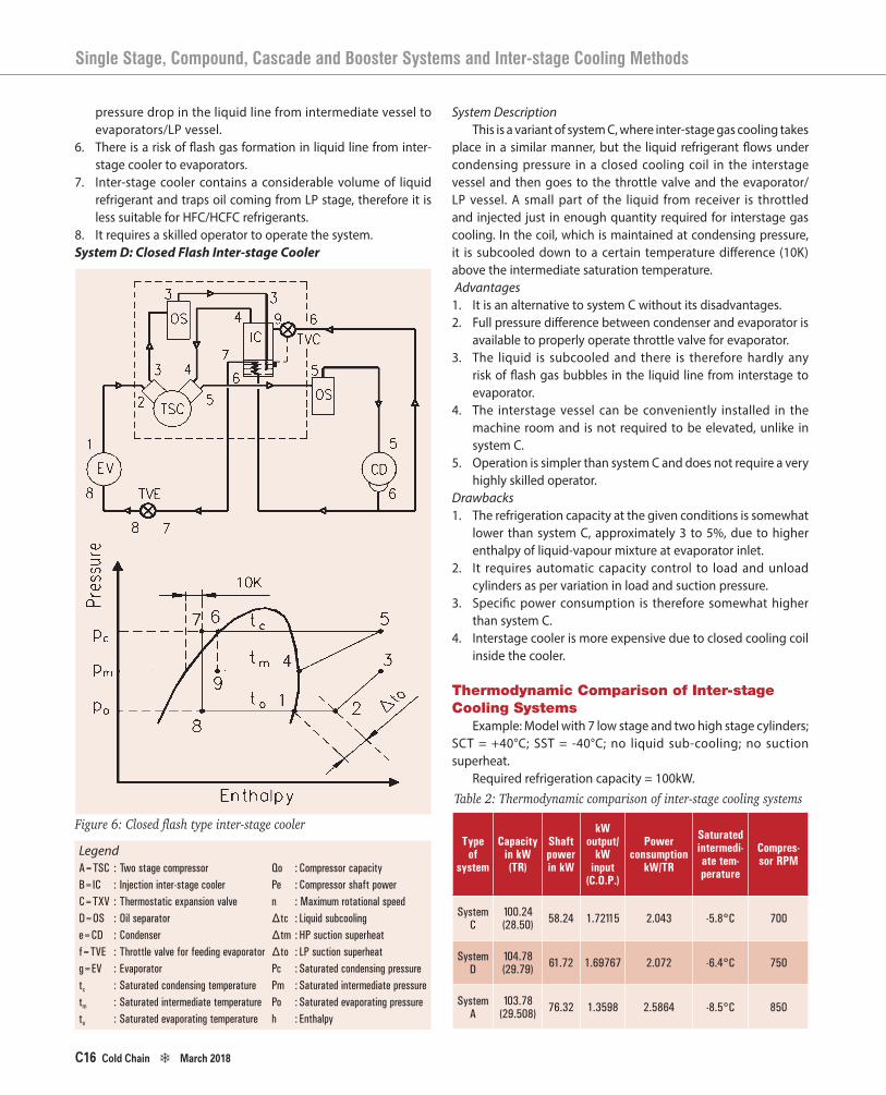
System DescriptionThis is a variant of system C, where inter-stage gas cooling takes
place in a similar manner, but the liquid refrigerant flows under condensing pressure in a closed cooling coil in the interstage vessel and then goes to the throttle valve and the evaporator/LP vessel. A small part of the liquid from receiver is throttled and injected just in enough quantity required for interstage gas cooling. In the coil, which is maintained at condensing pressure, it is subcooled down to a certain temperature difference (10K) above the intermediate saturation temperature. Advantages1. It is an alternative to system C without its disadvantages.2. Full pressure difference between condenser and evaporator is
available to properly operate throttle valve for evaporator.3. The liquid is subcooled and there is therefore hardly any
risk of flash gas bubbles in the liquid line from interstage to evaporator.
4. The interstage vessel can be conveniently installed in the machine room and is not required to be elevated, unlike in system C.
5. Operation is simpler than system C and does not require a very highly skilled operator.
Drawbacks1. The refrigeration capacity at the given conditions is somewhat
lower than system C, approximately 3 to 5%, due to higher enthalpy of liquid-vapour mixture at evaporator inlet.
2. It requires automatic capacity control to load and unload cylinders as per variation in load and suction pressure.
3. Specific power consumption is therefore somewhat higher than system C.
4. Interstage cooler is more expensive due to closed cooling coil inside the cooler.
Thermodynamic Comparison of Inter-stage Cooling Systems
Example: Model with 7 low stage and two high stage cylinders; SCT = +40°C; SST = -40°C; no liquid sub-cooling; no suction superheat.
Required refrigeration capacity = 100kW.Table 2: Thermodynamic comparison of inter-stage cooling systems
Type of
system
Capacity in kW (TR)
Shaft power in kW
kW output/
kW input
(C.O.P.)
Power consumption
kW/TR
Saturated intermedi-ate tem-perature
Compres-sor RPM
System C
100.24 (28.50) 58.24 1.72115 2.043 -5.8°C 700
System D
104.78 (29.79) 61.72 1.69767 2.072 -6.4°C 750
System A
103.78 (29.508) 76.32 1.3598 2.5864 -8.5°C 850
Figure 6: Closed flash type inter-stage cooler
LegendA=TSC : Two stage compressor Qo : Compressor capacityB=IC : Injection inter-stage cooler Pe : Compressor shaft powerC=TXV : Thermostatic expansion valve n : Maximum rotational speedD=OS :Oilseparator ∆tc :Liquidsubcoolinge=CD :Condenser ∆tm :HPsuctionsuperheatf=TVE :Throttlevalveforfeedingevaporator ∆to :LPsuctionsuperheatg=EV : Evaporator Pc : Saturated condensing pressuretc : Saturated condensing temperature Pm : Saturated intermediate pressuretm : Saturated intermediate temperature Po : Saturated evaporating pressureto : Saturated evaporating temperature h : Enthalpy
Single Stage, Compound, Cascade and Booster Systems and Inter-stage Cooling Methods
C16 Cold Chain d March 2018

17
From Table 2, we can observe the following: i. System C has the maximum C.O.P. and therefore best
efficiency. ii. System C has the lowest power consumption per unit
output. iii. System C has the lowest compressor speed, meaning
longer life, less wear and tear. iv. System C has the highest intermediate pressure and
temperature, which means lowest high stage compression ratio, lowest discharge gas temperature at the outlet of high stage cylinders, resulting in better lubricating properties, less overheating and lower inlet gas temperatures to condenser.
Cascade Systems
For low temperature applications, two independent circuits known as cascade systems are also commonly used.
The high stage circuit is a standard single stage refrigeration unit; however, the evaporator of this unit acts as the condenser for the low stage unit.
The low stage circuit is also a single stage standard refrigeration unit; however, the condenser of the low stage circuit is the evaporator of high stage unit. Thus, heat rejection of low stage is done by the boiling of high stage liquid and in the process the low stage gas gets condensed.Application Areas1. Very low temperature applications.2. Different load patterns for high and low stage.3. Very high difference between saturated evaporating and
condensing temperatures.
Advantages1. Simplicity of operation.2. Regular operator can manage the plant.3. No oil circulation and oil return problems.4. Three-stage cascade system is also possible.5. One can use different refrigerants for high stage and low stage
to achieve better results, which is not possible in two-stage single compressor design. For example, one can use ammonia for high stage and carbon dioxide for low stage. This is not possible in compound two-stage systems as they use the same refrigerant for high and low stage
6. High stage system can function independently without low stage system running, in case temperature requirements are high. This happens many times in cold rooms when very low temperature rooms are not loaded with products.
7. Different design of compressors can be used for high and low stage. One can use reciprocating compressor for high stage and screw compressor for low stage or both the stages with either reciprocating or screw compressors.
8. Load patterns for high stage and low stage can be different. For example, load on high stage could be much higher if the appli-cation warrants, and a very small system could be used for low stage if the load requirement is substantially lower. This happens often in a multipurpose cold storage facility when only one small room is used for storing, say, ice cream at -25°C whereas the main facility is used for storing fruits and vegetables at +2°C.Thus, there is total flexibility available to the system designer
if he opts for a cascade system instead of single two-stage compressor selection.Drawbacks1. Cascade condenser heat transfer requires temperature
differential penalty in the form of increased size and power compared to a two-stage open flash intercooler system.
2. First cost is somewhat higher due to the additional condenser-cum-evaporator, two compressors and two motors.
3. Liquid sub cooling has its limitations.4. Expansion valves need to be sized for relatively low pressure
differentials.5. Occupies more space and requires engineering and designing
skills for vessels, pipe routing, control selection, etc. 6. Quite often the low temperature circuit, using refrigerants like
R507, R-23 or carbon dioxide, may have very high pressures at standing conditions and hence a large volume expansion vessel is required to be provided in the system to allow the entire system gas of low stage to expand in the vessel without exceeding allowable pressures.
Two-stage vs. Cascade SystemMany consultants and designers of refrigeration systems
prefer cascade systems over two-stage systems, claiming that it gives better efficiency. We shall therefore now compare two-stage system vs. cascade system for identical conditions using ammonia refrigerant
Figure 7: A cascade refrigeration system
Cold Chain d March 2018 C17

18
We shall consider operating conditions as +40°C saturated condensing temperature and -30°C saturated suction temperature, and capacity as 100kW at -30°C. For the sake of comparison we shall consider two-stage KC42 compressor so that the cylinder ratio is 2:1 and therefore ideal with system C using open interstage cooling flash cooler.
For the cascade system we shall use KC4 compressor as low stage booster operating at -30°C evaporating and -5°C condensing temperature. For high stage we shall select KC3 single stage 3-cylinder compressor operating at +40°C condensing and -10°C evaporating temperature.
The heat exchanger would have thus 5°C TD (∆T).Ammonia-CO2 Cascade Systems
Since ammonia is generally not used for very low temperatures without encountering vacuum operation (below-33°C), and is not permitted where public may be exposed to ammonia gas leaks, systems using ammonia for high stage remotely located in the plant room and CO2 as a secondary coolant in the low stage, cooled by ammonia in the high stage, are gaining popularity especially for supermarket applications. This confines ammonia to the machine room, and thus benefits of high thermodynamic efficiency of ammonia may be derived with relatively low refrigerant charge. The volumetric capacity-density of CO2 being extremely high – nearly 8 times that of ammonia – makes the system compact and competitive to install.
The advantage of such a system is that it is thermodynamically efficient and uses both the natural environmentally friendly refrigerants having zero ODP and GWP.
Conclusion1. Power consumption per ton is lower with single frame two-
stage compressor than with cascade system, because the latter has inefficiency due to additional heat exchanger working as condenser for low stage and evaporator for high stage.
2. Power consumption is nearly 22% higher than two-stage compressor with open flash cooler.
3. A booster high stage cascade system requires in all 7 cylinders of the same swept volume as against 6 for two-stage compressor.Thermodynamic comparison, however, would not lead to the
conclusion that two-stage system is always a better alternative. Designers who have gone for cascade systems have never
regretted the choice; it has other obvious advantages that are not possible with two staging, such as easier oil management, simplicity in design, independent circuits, flexibility of compressor types and selection of different refrigerants as well as selecting optimum intermediate pressure and temperature levels.
References1. ASHRAE Handbook – Refrigeration2. Tested Solutions to Design Problems, Melvin A Ramsey3. Low Temperature Refrigeration, Rudy Stegmann, ASHRAE
Journal, January 20004. ASHRAE Journal, May 20005. Manual for Application of Two Stage Compressors, Grasso
Netherlands6. IIAR technical paper presentation, May 1986
Table 3: Thermodynamic comparison of two-stage vs. cascade systems
System type Compressor Model-RPM Operating conditions Capacity in kW(TR) Power consumption in kW kW/TR
Booster – low stage KC4-650 RPM -30°C/-5°C 100.56 (28.59) 17.36
Highstage KC3-600 RPM +40°C/-10°C 128.51 38.34
Total 100.56 (28.59) 55.7 1.948
Single frame two stage KC42-650RPM +40°C/-30°C 101.08 (28.74) 45.82 1.5942
Single Stage, Compound, Cascade and Booster Systems and Inter-stage Cooling Methods
C18 Cold Chain d March 2018