a sandwich-structure composite membrane as separator with
TRANSCRIPT

Int. J. Electrochem. Sci., 14 (2019) 7088 – 7103, doi: 10.20964/2019.08.60
International Journal of
ELECTROCHEMICAL
SCIENCE www.electrochemsci.org
A Sandwich-Structure Composite Membrane as Separator with
High Wettability and Thermal Properties for Advanced
Lithium-Ion Batteries
Yang Li1,2, Jiang Cao2,3,*, Qi Liu2, Aoxuan Wang1,*, Baohua Li2
1 State Key Laboratory of Chemical Engineering, School of Chemical Engineering and Technology,
Tianjin University, Tianjin, 300350, China 2 Division of Energy and Environment, Engineering Laboratory for the Next Generation Power and
Energy Storage Batteries, Graduate School at Shenzhen, Tsinghua University, Shenzhen 518055,
China 3 R&D Center, Shenzhen Senior Technology Material Co., LTD, Shenzhen 518106, China *E-mail: [email protected] , [email protected]
Received: 2 April 2019 / Accepted: 31 May 2019 / Published: 30 June 2019
Lithium-ion batteries with high energy density and environmental friendliness have attracted
considerable interest for reseachers in recent years. However, the conventional polyolefin separators
with poor electrolyte wettability and low thermal stability limited the further development of lithium-
ion batteries. Here we designed a porous poly(m-phenylene isophthalamide) (PMIA) layer, embedded
with high-dispersed TiO2-P(MMA-AA-BA) (TP) nanohybrid, on both sides of a polyethylene (PE)
membrane by a facile nonsolvent-induced phase inversion process to improve the electrolyte wettability
and thermal stability of the PE separator. The TP nanoparticles can disperse uniformly in PMIA layer.
Due to the inherent high-heat resistance and good affinity to the liquid electrolyte of PMIA and
nanohybrid, this (TP-PMIA)-modified PE (TP-PMIA@PE) membrane exhibits high porosity, high ionic
conductivity, improved thermal resistance and superior interfacial stability, which can endow the
composite membrane-based Li/LiFePO4 cell with good capacity retention and superior rate capability.
The as-prepared composite membrane can serve as a promising separator for high-safety and high-
performance lithium-ion batteries.
Keywords: Poly (m-phenylene isophthalamide); Nanohybrid ; Phase inversion process; Separator;
Lithium-ion batteries
1. INTRODUCTION
In the past decades, lithium-ion batteries (LIBs) have been widely applied in portable electronic,
electric vehicles and energy storage systems due to their high energy density, excellent cycle life, low
self-discharge rate and environmental friendliness [1,2]. A traditional lithium-ion battery is mainly

Int. J. Electrochem. Sci., Vol. 14, 2019
7089
composed of cathode, anode, separator and electrolyte [3,4]. The separator is a key component in a
lithium-ion battery, which is used to prevent short circuit by separating the cathode and anode and allow
lithium-ions transport between the electrodes during the charging and discharging processes. Therefore,
the property of separator is vital for the battery performance [5,6].
Up to now, the commercial microporous polyolefin separators, such as polypropylene (PP),
polyethylene (PE) and their composite membrane (PP/PE/PP), have been widely used in LIBs, due to
their good chemical stability, excellent mechanical strength as well as the acceptable cost. However,
some inherent drawbacks of polyolefin separators, including low porosity, inferior thermal stability and
poor electrolyte wettability, may hinder their application for advanced LIBs to some extent [7]. The low
porosity and poor electrolyte wettability of polyolefin membranes are derived from their intrinsic
nonpolar properties, which may lead to low ionic conductivity, high cell resistance and poor rate
performance of the LIBs. In particular, the low melting point of polyolefin separators makes them suffer
great thermal shrinkages when the batteries work under high temperatures, leading to internal short
circuit and even ignition or explosion [8]. To solve the abovementioned shortcomings of polyolefin
separators, extensive efforts have been devoted to surface modification of polyolefin separators. One
effective method is to introduce inorganic nanoparticles coating layers onto the membrane surfaces, such
as silicon dioxide (SiO2) [9,10], aluminum oxide (Al2O3) [11], zirconia (ZrO2) [14] and titanium dioxide
(TiO2) [12,13] etc. The nano-sized inorganic particles can significantly enhance the thermal stability and
electrolyte wettability of separators. For example, Kim et al. introduced an amino-functionalized SiO2
particles to the surface of PE separator. The obtained composite membrane exhibited good electrolyte
wettability, high ionic conductivity and enhanced thermal stability, which showed superior cycling
stability and thermal safety of LIBs [9]. Zhao et al. developed a ceramic coating separator by introducing
Al2O3 powder and thermal stable polymer binder (polyimide) onto the surface of a PE membrane,
leading to the improved safety and high capacity retention for LIBs [11]. Although the composite
membranes with ceramic coating possess excellent electrolyte wettability and good thermal stability, a
certain amount of ceramic nanoparticles will aggregate and inevitably block the pores of the polymer
matrix. Moreover, the applied binders are easily swelling and gelling in the liquid electrolyte, resulting
in shedding of particles from the substrate. The polymer-based coating is another strategy to modify the
polyolefin membranes, including aramid nanofiber (ANF) [15], polybenzimidazole (PBI) [16],
polydopamine (PDA) [17]. By introducing the polymer onto the surface of polyolefin membranes, the
prepared composite membranes exhibit high thermal stability and good affinity with liquid electrolyte.
Nevertheless, this method may also lead to some drawbacks, such as pore blocking and multistep
operations.
It is well known that the aramid possesses high strength, high flame resistance, superior heat
resistance and high electrical insulation, which is widely used as electrical insulating materials, special
protective apparels, high temperature filter materials, etc [18-20]. Poly (meta-phenylene isophthalamide)
(PMIA), also widely known as meta-aramid, exhibits high mechanical property and superior thermal
stability (up to 400 °C). In addition, the PMIA polymer may have superior wettability with liquid
electrolyte due to the polar carbonyl groups in it [21]. In recent years, some researchers have used PMIA
or PMIA-based composite membranes as separators of LIBs, such as the PVdF/PMIA/PVdF nanofibrous
composite membrane [22], F-doped PMIA nanofibrous membrane [23], the SiO2/PMIA nanofiber
Int. J. Electrochem. Sci., Vol. 14, 2019
7090
membrane [24]. All of these preparation methods are sophisticated, time-consuming and high
manufacturing cost, which are not desirable for the large-scale application. Zhu et al. prepared a
microporous PMIA separator by phase separation process [25]. Although the PMIA separator showed
high thermal stability, which was beneficial for the safety of batteries, it exhibited no thermal shutdown
function and the cost was relatively high.
In this paper, we designed a composite membrane with the three-dimensional (3D) porous TP-
PMIA layers on both sides of a PE membrane by a facile phase inversion method with low cost,
combining the advantages of polymer and inorganic nanoparticles. A small amount of TiO2 nanoparticles
are distributed uniformly and 3D porous structure can avoid pore blocking of PE matrix effectively.
Compared with the bare separator, the obtained porous composite membrane exhibits excellent
electrolyte wettability and higher dimensional thermal stability. Thus, the cells assembled with the
composite membranes perform high interfacial stability, stable cycle performance and superior rate
capability. In addition, the composite membrane shows a shutdown function at high temperature due to
the low-melting PE layer. The characterization of the composite membrane was investigated in this
paper.
2. EXPERIMENTAL
2.1. Materials
Poly(m-phenylene isophthalamide) (PMIA) was obtained from Teijin Ltd., Japan. N, N-
Dimethylacetamide (DMAc) and Lithium chloride (LiCl) was supplied by Aladdin Industrial Co., China.
Methyl methacrylate (MMA), acrylic acid (AA) and butyl methacrylate (BA) were provided from
Sinopharm Chemical Reagent Co.,Ltd., China. The potassium persulfate and tritonX-100 were
purchased from Shanghai Aladdin Biochemical Technology Co., Ltd., China. TiO2 nanoparticals were
purchased from Hangzhou Wanjing New Materials Co., Ltd., China. The microporous polyethylene (PE,
thickness 12 µm) membrane were purchased from Shenzhen Xingyuan Materials Technology Co., Ltd.,
China., which were used as commercial separators of lithium-ion batteries for a contrasting test. All the
chemical reagents were used directly without further purification.
2.2. Synthesis of TP nanospheres
In this experiment, a certain amount of TiO2 nanopaticals were dispersed in deionized water by
ultrasonication. The mixture of methyl methacrylate, acrylic acid and butyl methacrylate (MMA-AA-
BA) was added to the aqueous solution with mechanical stirring (MMA-AA-BA: TiO2=80: 20, in mass).
Then, the emulsifying agent (tritonX-100) and the initiator (potassium persulfate) were also added
slowly to the solution. The emulsion polymerization was carried out in oven for 4 h at 85 °C. Then the
TiO2-P(MMA-AA-BA) (TP) nanospheres were obtained successfully.
Int. J. Electrochem. Sci., Vol. 14, 2019
7091
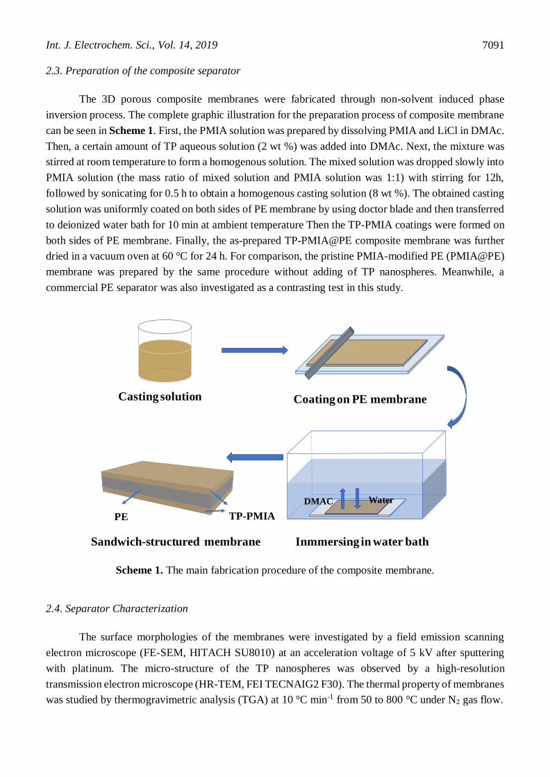
2.3. Preparation of the composite separator
The 3D porous composite membranes were fabricated through non-solvent induced phase
inversion process. The complete graphic illustration for the preparation process of composite membrane
can be seen in Scheme 1. First, the PMIA solution was prepared by dissolving PMIA and LiCl in DMAc.
Then, a certain amount of TP aqueous solution (2 wt %) was added into DMAc. Next, the mixture was
stirred at room temperature to form a homogenous solution. The mixed solution was dropped slowly into
PMIA solution (the mass ratio of mixed solution and PMIA solution was 1:1) with stirring for 12h,
followed by sonicating for 0.5 h to obtain a homogenous casting solution (8 wt %). The obtained casting
solution was uniformly coated on both sides of PE membrane by using doctor blade and then transferred
to deionized water bath for 10 min at ambient temperature Then the TP-PMIA coatings were formed on
both sides of PE membrane. Finally, the as-prepared TP-PMIA@PE composite membrane was further
dried in a vacuum oven at 60 °C for 24 h. For comparison, the pristine PMIA-modified PE (PMIA@PE)
membrane was prepared by the same procedure without adding of TP nanospheres. Meanwhile, a
commercial PE separator was also investigated as a contrasting test in this study.
Scheme 1. The main fabrication procedure of the composite membrane.
2.4. Separator Characterization
The surface morphologies of the membranes were investigated by a field emission scanning
electron microscope (FE-SEM, HITACH SU8010) at an acceleration voltage of 5 kV after sputtering
with platinum. The micro-structure of the TP nanospheres was observed by a high-resolution
transmission electron microscope (HR-TEM, FEI TECNAIG2 F30). The thermal property of membranes
was studied by thermogravimetric analysis (TGA) at 10 °C min-1 from 50 to 800 °C under N2 gas flow.
DMAC Water
Casting solution Coating on PE membrane
Inmmersing in water bath Sandwich-structured membrane
PE TP-PMIA

Int. J. Electrochem. Sci., Vol. 14, 2019
7092
The thermal shrinkage of the membranes (size:3 cm×3 cm) was investigated by measuring the
dimensional change after storing them in an oven at different temperatures (100 °C, 110 °C, 120 °C, 130
°C, 140 °C, 150 °C and 160 °C ) for 0.5 h. The thermal shrinkage percentage (area-based) was calculated
by the following equation.
𝑆ℎ𝑟𝑖𝑛𝑘𝑎𝑔𝑒 (%) = (𝑆0 − 𝑆1) 𝑆0⁄ × 100% (1)
where the S0 and S1 represent the area of separators before and after the heat treatment,
respectively.
Liquid electrolyte uptake measurement of the membranes was performed by immersing
membranes in the electrolyte (1 M LiPF6 in EC/DMC/EMC (1:1:1)) at 25 °C for 2 h in a glove box and
then measured the weight change between the dry state and the soaked state of the membranes. The
electrolyte uptake (U) was calculated according to the following equation.
𝑈 (%) = (𝑊1 − 𝑊0) × 100% (2)
where the W1 and W0 refer to the mass of the soaked and dry membrane, respectively.
To study the wettability of the membrane, the electrolyte contact angle measurement of the
samples was carried out by a contact angle goniometer (DSA30) in air atmosphere, where a droplet of
electrolyte was dropped onto the surface of the membrane.
For the porosity testing, the membrane was immersed into n-butanol for 2 h until the equilibrium
was achieved, and then the weight of the saturated and dry membranes was measured, respectively. The
porosity was calculated by the following equation:
𝑃 (%) = (𝑀1 − 𝑀0) (𝜌 × 𝑉)⁄ × 100% (3)
where P represents porosity of the membrane, M1 and M0 are the weight of the soaked and dry
membrane, respectively, ρ is the density of the n-butanol, and V stands for the volume of the membrane.
2.5. Electrochemical performance
Ionic conductivity (σ) can be calculated according to the following formula:
𝜎 = 𝑑 (𝑅𝑏 × 𝑆)⁄ (4)
where Rb is the bulk impedance (ohm), d indicates the thickness (cm) of the membrane, S
represents the effective contact area between stainless steel discs and membrane. Rb was obtained by
electrochemical impedance spectroscopy (EIS) using an electrochemical working station (Bio Logic
Science Instruments) at room temperature.
The liquid electrolyte soaked membrane was sandwiched between the two stainless steel discs.
The EIS tests were conducted at scanning frequencies ranging from 0.1 Hz to 100 kHz, with an amplitude
of 5 mV.
The electrochemical stability window of the prepared membrane was investigated by linear
sweep voltammetry (LSV) test. Before the measurement, the coin cell (lithium/separator/stainless steel)
was assembled and sealed in the argon-filled glovebox. In our test, the stainless steel was used as the
working electrode, while the lithium electrode as the reference and counter electrode, and the potential
range was from 2.5 to 5.5V (vs. Li+/Li) at 1 mV s-1.

Int. J. Electrochem. Sci., Vol. 14, 2019
7093
A LAND battery testing equipment (Wuhan, China) was used to evaluate the charge and
discharge properties of the assembled button cell at room temperature. The coin-type half cell was
assembled in a glove box filled with argon gas with the moisture and oxygen content below 0.01 ppm.
The prepared membrane was used as separator, 1 M LiPF6 in EC/DMC/EMC (1:1:1 vol), lithium metal
and LiFePO4 were employed as electrolyte, anode and cathode respectively. The LiFePO4 cathode was
prepared by mixing LiFePO4 powder (80 wt%), Super P (10 wt%) and PVDF binder (10 wt%) in the N-
methyl-2-pyrrolidone (NMP) solvent, then casting the slurry on the aluminum foil and drying at 60°C
for 24 h. The charge/discharge cycling test was performed at a constant current density of 0.5 C for 100
cycles in a voltage window of 2.5 to 4 V at room temperature. For the rate performance measurement,
the battery was charged and discharged at varied current densities of 0.2 C, 0.5 C, 1 C, 2 C and 5 C for
5 cycles respectively and finally returned to 0.2 C. Both cycle performance and rate performance
measurements of the battery were activated at 0.1C for 3 cycles to form a stable solid electrolyte interface
(SEI).
3. RESULTS AND DISCUSSION
3.1 morphology analysis
Figure 1. SEM images (a, b) and TEM micrographs (c, d) of the TP nanospheres
The core-shell structured TP nanospheres were synthesized. Fig. 1 shows the SEM images (a, b)
and TEM micrographs (c, d) of the as-prepared TP nanospheres. As can be seen from Fig. 1a and b,
Int. J. Electrochem. Sci., Vol. 14, 2019
7094
these nanospheres exhibit a good monodisperse distribution and have a uniform spherical structure with
an average diameter of 100 nm. The size and the core-shell structure of the TP nanospheres are obtained
from the Fig. 1c and d, which are consistent with the SEM images. Such core-shell structure is similar
to the structure of SiO2-PMMA sub-microspheres reported by Yang [26] Every TP nanosphere is
composed of the P(MMA-AA-BA) shell (light area) and several TiO2 core particles (dark area)
surrounded by P(MMA-AA-BA). TEM micrographs indicate that the TiO2 particles are well
encapsulated by P(MMA-AA-BA).
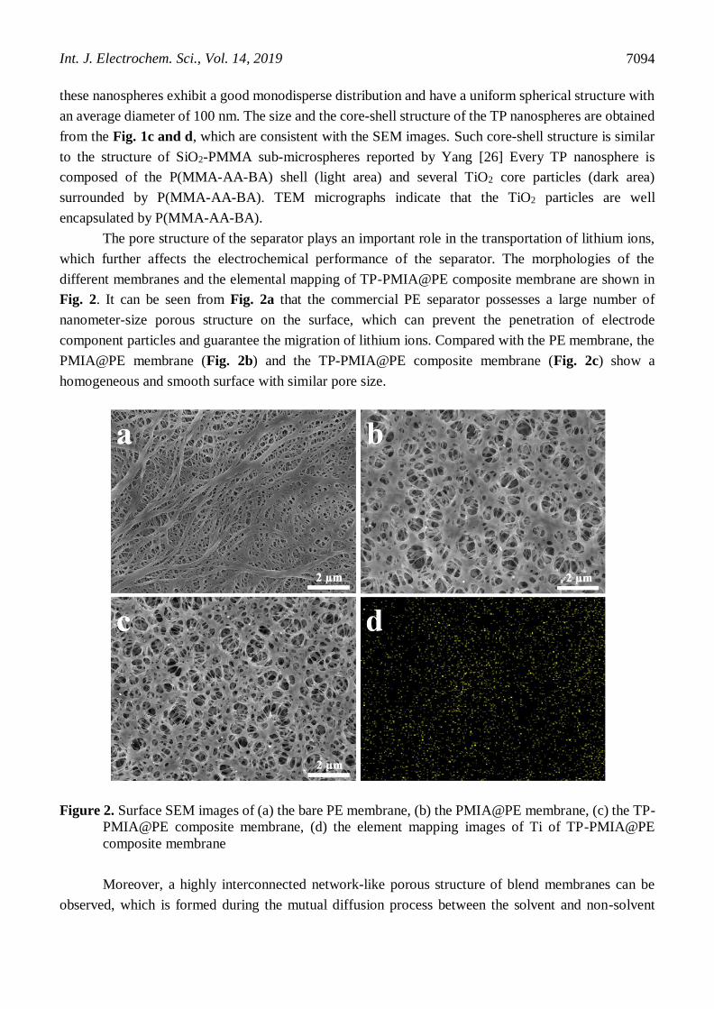
The pore structure of the separator plays an important role in the transportation of lithium ions,
which further affects the electrochemical performance of the separator. The morphologies of the
different membranes and the elemental mapping of TP-PMIA@PE composite membrane are shown in
Fig. 2. It can be seen from Fig. 2a that the commercial PE separator possesses a large number of
nanometer-size porous structure on the surface, which can prevent the penetration of electrode
component particles and guarantee the migration of lithium ions. Compared with the PE membrane, the
PMIA@PE membrane (Fig. 2b) and the TP-PMIA@PE composite membrane (Fig. 2c) show a
homogeneous and smooth surface with similar pore size.
Figure 2. Surface SEM images of (a) the bare PE membrane, (b) the PMIA@PE membrane, (c) the TP-
PMIA@PE composite membrane, (d) the element mapping images of Ti of TP-PMIA@PE
composite membrane
Moreover, a highly interconnected network-like porous structure of blend membranes can be
observed, which is formed during the mutual diffusion process between the solvent and non-solvent

Int. J. Electrochem. Sci., Vol. 14, 2019
7095
[27,28]. It is consistent with the previous report [25] that the membrane exhibited numerous
interconnected pores, which was beneficial for the storage of liquid electrolyte and migration of lithium
ions [29]. This special structure is helpful to avoid blocking the pore structure of matrix. A uniform
distribution of element Ti in the TP-PMIA@PE composite membrane is observed in Fig. 2d, suggesting
that the TiO2 nanoparticals in the membrane are distributed uniformly.
3.2 separator properties analysis
Various physical and chemical properties of the PE, PMIA@PE and TP-PMIA@PE membranes
are summarized in Table 1. The thicknesses of the two kinds of composite membranes are 20 μm and
24 μm respectively, thicker than pristine PE membrane (12 μm). However, the thickness of the composite
membrane is suitable for separator of LIBs in portable electronic devices and electric vehicle
applications [30]. The porosity of a separator is a crucial factor for electrochemical properties of LIBs.
As shown in Table 1, the porosities of the PMIA@PE (58%) and TP-PMIA@PE membranes (67%) are
higher than pristine PE membrane (40%), owing to the interconnected porous structure formed by non-
solvent induced phase inversion process [31]. The addition of TP nanospheres affects the formation of
pore structure to some extent. The TP-PMIA@PE composite membrane with high porosity possibly
exhibits high liquid electrolyte uptake, further leading to a high ionic conductivity, which is consistent
with the paper in Cao [32].
Table 1. Physical and chemical properties of different membranes
Sample Thickness
(μm)
Porosity
(%)
Electrolyte
uptake (%)
Electrolyte contact
angle (deg)
Ion conductivity
(S cm-1 )
PE 12 40 105 36 6.42×10⁻⁴
PMIA@PE 20 58 202 10 6.00×10⁻⁴
TP-PMIA@PE 24 67 254 8 7.90×10⁻⁴
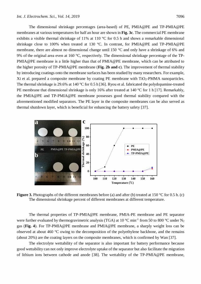
It is acknowledged that thermal stability of the separator is another vital parameter to evaluate
the safety of batteries. A separator with good thermal stability can prevent internal short circuit of
batteries at elevated temperature [33]. Fig. 3a and b show the photographs of PE, PMIA@PE and TP-
PMIA@PE membranes before and after treating at 150 °C for 0.5 h, respectively. The PE membrane
shows a serious dimensional shrinkage with obvious color change from white to transparent due to its
inherent low melting point (130 °C) [30]. In contrast, the composite membranes of PMIA@PE and TP-
PMIA@PE maintain the original dimension due to the introduction of high heat-resistance TP-PMIA
coatings onto the both sides of the PE membrane [34,35]. The above results indicate that the composite
membranes of PMIA@PE and TP-PMIA@PE can suppress thermal shrinkage effectively, further to
prevent internal short circuit of batteries.
Int. J. Electrochem. Sci., Vol. 14, 2019
7096
The dimensional shrinkage percentages (area-based) of PE, PMIA@PE and TP-PMIA@PE
membranes at various temperatures for half an hour are shown in Fig. 3c. The commercial PE membrane
exhibits a visible thermal shrinkage of 11% at 110 °C for 0.5 h and shows a remarkable dimensional
shrinkage close to 100% when treated at 130 °C. In contrast, for PMIA@PE and TP-PMIA@PE
membrane, there are almost no dimensional change until 150 °C and only have a shrinkage of 6% and
9% of the original area even at 160 °C, respectively. The dimensional shrinkage percentage of the TP-
PMIA@PE membrane is a little higher than that of PMIA@PE membrane, which can be attributed to
the higher porosity of TP-PMIA@PE membrane (Fig. 2b and c). The improvement of thermal stability
by introducing coatings onto the membrane surfaces has been studied by many researchers. For example,
Xi et al. prepared a composite membrane by coating PE membrane with TiO2-PMMA nanoparticles.
The thermal shrinkage is 29.6% at 140 °C for 0.5 h [36]. Ryou et al. fabricated the polydopamine-treated
PE membrane that dimensional shrinkage is only 16% after treated at 140 °C for 1 h [17]. Remarkably,
the PMIA@PE and TP-PMIA@PE membrane possesses good thermal stability compared with the
aforementioned modified separators. The PE layer in the composite membranes can be also served as
thermal shutdown layer, which is beneficial for enhancing the battery safety [37].
Figure 3. Photographs of the different membranes before (a) and after (b) treated at 150 °C for 0.5 h. (c)
The dimensional shrinkage percent of different membranes at different temperature.
The thermal properties of TP-PMIA@PE membrane, PMIA-PE membrane and PE separator
were further evaluated by thermogravimetric analysis (TGA) at 10 °C min-1 from 50 to 800 °C under N2
gas (Fig. 4). For TP-PMIA@PE membrane and PMIA@PE membrane, a sharply weight loss can be
observed at about 460 °C owing to the decomposition of the polyethylene backbone, and the remains
(about 20%) are the coating layers on the composite membranes, which is confirmed by Wan [37].
The electrolyte wettability of the separator is also important for battery performance because
good wettability can not only improve electrolyte uptake of the separator but also facilitate the migration
of lithium ions between cathode and anode [38]. The wettability of the TP-PMIA@PE membrane,
100 110 120 130 140 150 160
0
20
40
60
80
100
Temperature (oC)
Th
erm
al
shrin
ka
ge (
%)
PE
PMIA@PE
TP-PMIA@PE
a
b
c
PE PMIA@PE TP-PMIA@PE

Int. J. Electrochem. Sci., Vol. 14, 2019
7097
PMIA@PE membrane and bare PE membrane is evaluated by the contact angle test, respectively. As
shown in Fig. 5a, a certain amount of liquid organic electrolyte was simultaneously dropped onto the
surface of each membrane and then the diffuse phenomenon of the electrolyte was observed.
Figure 4. TGA curves of the bare PE membrane, the PMIA@PE membrane, the TP-PMIA@PE
composite membrane.
The electrolyte droplet on the TP-PMIA@PE and PMIA@PE membranes spread quickly and
became transparent due to the absorption of liquid electrolyte, whereas the electrolyte droplet was kept
for a long time on the bare PE separator. Fig. 5b depicts that the electrolyte contact angles of the
PMIA@PE and TP-PMIA@PE composite membranes are 10° and 8° respectively, which are much
lower than that of the pristine PE membrane (36°), indicating a strong affinity towards liquid electrolyte
of the composite membranes. The superior electrolyte wettability of the composite membranes can be
ascribed to the presence of polar carbonyl groups and amine groups in PMIA and the TiO2 nanospheres
[25,34]. The inherent hydrophobicity of PE membrane results in poor wettability with liquid electrolyte.
The electrolyte uptake of the separator was measured by immersing membranes in the electrolyte
in a glove box, summarized in Table 1. The high electrolyte uptake will facilitate the migration of lithium
ions and is beneficial to improve the ionic conductivity, leading to superior rate capability of batteries.
The TP-PMIA@PE and PMIA@PE membrane exhibit a high electrolyte uptake of 254% and 202%,
respectively, which are much higher than that of PE membrane (105%). Therefore, the composite
membranes possess the high electrolyte uptake, which is attributed to their excellent wettability with
electrolyte and high porosity [39]. Moreover, the electrolyte uptake of the TP-PMIA@PE membrane is
higher than that of PMIA@PE membrane due to the high porosity and the P(MMA-AA-BA) shells of
TP nanospheres. The special structure of shells becomes gelled in the electrolyte after adsorbing a certain
amount of electrolyte in the coating layers. [40].
0 200 400 600 8000
20
40
60
80
100
W
eig
ht
(%)
Temperature (oC)
PE
PMIA@PE
TP-PMIA@PE

Int. J. Electrochem. Sci., Vol. 14, 2019
7098
Figure 5. (a) Photograph of the wettability of PE membrane, PMIA@PE membrane and TP-PMIA@PE
membrane with liquid electrolyte. (b) Electrolyte contact angles of different membranes.
Figure 6. Electrochemical measurements of PE, PMIA@PE and TP-PMIA@PE membranes. (a) Nyquist
plots with the different membranes, (b) AC impedance spectra of LiFePO4/Li cells after 100th
cycle, and (c) Linear sweep voltammograms of Li/separator/SS cells.
0 2 4 6 80
2
4
6
8
-Z(o
hm
)
Z(ohm)
PE
PMIA@PE
TP-PMIA@PE
0 20 40 60 80 1000
20
40
60
80
100
-Z''
(oh
m)
Z'(ohm)
PE
PMIA@PE
TP-PMIA@PE
a b
c
2.5 3.0 3.5 4.0 4.5 5.0 5.5-0.05
0.00
0.05
0.10
0.15
0.20
Cu
rren
t (m
A)
Potential (Vvs Li+/Li)
PE
PMIA@PE
TP-PMIA@PE

Int. J. Electrochem. Sci., Vol. 14, 2019
7099
The ionic conductivity of the membrane was studied by EIS tests at room temperature. The bulk
resistance (Rb) was obtained from the Z′ axis intercept in the Nyquist plot shown in Fig. 6a. Although
the Rb of the pristine PE separator is a little lower than the PMIA@PE and TP-PMIA@PE composite
membranes, the calculated ionic conductivity (0.79 mS cm-1) of the TP-PMIA@PE (shown in Table 1)
is higher than that (0.64 mS cm-1) of PE membrane due to the higher thickness of TP-PMIA@PE
membrane. By comparison, Li et al. developed a PBI/PE/PBI composite membrane with the ionic
conductivity of 0.6 mS cm-1 [37]. And the ionic conductivity of TiO2-grafted PE separator proposed by
Zhu was 0.5 mS cm-1 [13]. Therefore, the TP-PMIA@PE membrane exhibits the high ionic conductivity,
which should be ascribed to its high porosity with interconnected porous structure and the high
electrolyte uptake due to the introduction of the PMIA and nano-TiO2 hybrid [41]. The enhanced ionic
conductivity of the TP-PMIA@PE membrane can facilitate the migration of lithium ions and further
improve the rate capability of battery.
From Fig. 6b, it can be seen that AC impedance spectra of Li/LiFePO4 cells with the bare PE,
PMIA@PE and TP-PMIA@PE membranes after the 100th cycle at 0.5 C, are used to analyze the battery
impedance. The left crossover point of the semicircle with the Z′ axis represents the bulk resistance (Rb),
which includes the resistance of electrodes, electrolyte and separator. The semicircle and straight line
refer to the charge transfer resistance (Rct) between the electrode and electrolyte and the Warburg
impedance (Zw) about the lithium ion diffusion in LiFePO4 cathode, respectively [42]. The Rb of the
PMIA@PE and TP-PMIA@PE membrane are slightly larger than that of the PE membrane because of
the high thickness of the composite membrane. In contrast, the Rct of TP-PMIA@PE membrane is far
smaller than that of the bare PE and PMIA@PE membrane. The lower charge transfer resistance of TP-
PMIA@PE membrane is mainly attributed to its excellent liquid electrolyte wettability and high
porosity, facilitating the lithium ions migration and further improving the battery performance [43,44].
Electrochemical stability of the as-prepared membranes is a vital parameter for the application
of battery, which was evaluated by linear-sweep voltammetry (LSV) tests [45], as shown in Fig. 6c. It
can be observed clearly that the commercial PE membrane, PMIA@PE and TP-PMIA@PE composite
membranes are all stable with no obvious anodic currents until around 4.5 V vs Li+/Li. However, there
is a considerable rise in current flow when the potential exceeded 4.5 V, which should be related to the
oxidative decomposition of the membranes. Some reported research showed similar results [32,33,34].
The above result indicates that the composite membranes possess good electrochemical stability and can
be applied to practical LIBs [34]. The rate capability of Li/LiFePO4 batteries with different membranes
was measured and shown in Fig. 7. The discharge capacities of all batteries with the different membranes
gradually decrease with the increase of current density (Fig. 7a-c), ranging from 0.2 C to 5 C and finally
returning to 0.2 C every 5 cycles. At relatively low discharge rates of 0.2 C, 0.5 C and 1 C, the discharge
capacities are all very close for the three kinds of batteries (Fig. 7d). However, the difference in the
discharge capacities increases obviously at high current densities of 2 C and 5 C, especially at 5 C rate,
the cell with TP-PMIA@PE membrane exhibits a higher discharge-specific capacities of 128 mA h g-1
than that of the cells with PMIA@PE (114 mAh g-1) and pristine PE membrane (116 mAh g-1). The
discharge capacity retention of the battery with TP-PMIA@PE membrane at 5 C is about 82% of that at
0.2 C, which is much better than that of batteries with PMIA@PE (75%) and PE membrane (72%). The
excellent rate performance of the Li/LiFePO4 battery with TP-PMIA@PE membrane is mainly attributed

Int. J. Electrochem. Sci., Vol. 14, 2019
7100
to its excellent interfacial compatibility and its high ionic conductivity, which are favorable for lithium
ions transport.
Figure 7. The discharge curves of LiFePO4/separator/Li cells with (a) PE membrane, (b) PMIA@PE
membrane and (c) TP-PMIA@PE membrane. (d) Rate performance of LiFePO4/separator/Li
cells with different membranes at the current densities of 0.2 C, 0.5 C, 1 C, 2C and 5C.
Figure 8. Cycling performance of the cells (LiFePO4/separator/Li) with PE membrane, PMIA@PE
membrane and TP-PMIA@PE membrane at 0.5 C.
0 5 10 15 20 25 3060
80
100
120
140
160
180
Dis
cha
rge
cap
aci
ty (
mA
h/g
)
Cycle number
PE
PMIA@PE
TP-PMIA@PE
0.2C 0.5C1C
2C
5C
0.2C
a b
c d
PE PMIA@PE
TP-PMIA@PE
0 20 40 60 80 100 120 140 160 1802.4
2.6
2.8
3.0
3.2
3.4
3.6
3.8
Vo
lta
ge
(V)
Discharge capacity (mAh/g)
0.2C
0.5C
1C
2C
5C
0 20 40 60 80 100 120 140 160 1802.4
2.6
2.8
3.0
3.2
3.4
3.6
3.8
Vo
lta
ge
(V)
Discharge capacity (mAh/g)
0.2C
0.5C
1C
2C
5C
0 20 40 60 80 100 120 140 160 1802.4
2.6
2.8
3.0
3.2
3.4
3.6
3.8
Volt
ag
e (V
)
Discharge capacity (mAh/g)
0.2C
0.5C
1C
2C
5C
0 20 40 60 80 10080
100
120
140
160
180
Dis
ch
arg
e c
ap
acit
y (
mA
h/g
)
Cycle number
PE
PMIA@PE
TP-PMIA@PE

Int. J. Electrochem. Sci., Vol. 14, 2019
7101
Fig. 8 compares the cycling stability of Li/LiFePO4 coin cells assembled with three kinds of
membranes at 0.5 C under 2.5-4.0 V. For the cell with the TP-PMIA@PE membrane, the discharge
capacity retention is up to 100% after 100 cycles and almost maintain its initial capacity, which is higher
than the capacity retention of both PMIA-PE membrane (98.6%) and PE membrane (93.5%). The high
capacity retention and stable cycle performance of the TP-PMIA@PE membrane are attributed to its
highly developed nanoporous structure and superior affinity between membrane and electrolyte, which
are favorable for lithium ions transport and interface stability.
Various physical and electrochemical performances of different composite membrane separators
are listed in Table 2. It can be observed that the thermal stability, electrolyte uptake, ionic conductivity
and specific capacity of the cells with TP-PMIA@PE membrane in this work are excellent or comparable
to that of the cells with PE modified membranes in previous studies.
Table 2. Comparison of the various performance of other modified PE membrane separators
Sample Thickness
(μm)
Electrolyte
uptake
(%)
Thermal
shrinkage (%)
Ion
conductivity
(S cm-1 )
Specific capacity
(mAh g-1)
Ref.
PDA-coated PE 25 126 16
(140°C,1h)
4.10×10⁻⁴ 139
(0.1C, Li/LiCoO2)
[17]
SiO2-PMMA@PE 25 89.5 13
(130°C,0.5h)
10.8×10⁻⁴ 107
(0.1C,
graphite/LiFePO4)
[26]
TiO2-PMMA/PE 20 202 30
(140°C,0.5h)
8.70×10⁻⁴ ~130
(0.5C, Li/LiFePO4)
[36]
PBI/PE/PBI 28 225 0
(200°C, 1h)
5.96×10⁻⁴ ~148
(0.5C, Li/LiFePO4)
[37]
TP-PMIA@PE 24 254 0
(150°C,0.5h)
7.90×10⁻⁴ 154
(0.5C, Li/LiFePO4)
This
work
4. CONCLUSION
In this work, we successfully prepared a sandwich-structured TP-PMIA@PE composite
membrane by a facile nonsolvent-induced phase inversion process. Compared with PE membrane, the
obtained composite membrane possesses the improved physical and chemical properties by introducing
nanoporous TP-PMIA coating layers onto both sides of PE membrane. The TP-PMIA@PE composite
membrane shows high porosity (67%), excellent wettability with liquid electrolyte, high electrolyte

Int. J. Electrochem. Sci., Vol. 14, 2019
7102
uptake (254%), low interfacial resistance and high ionic conductivity (0.79 mS cm-1). In addition, due
to the introduction of high heat resistance TP-PMIA coating layers, the TP-PMIA@PE membrane
exhibits no dimensional shrinkage even at 150 °C. The battery assembled with the TP-PMIA@PE
membrane shows excellent rate property and cycle performance. In summary, the experimental results
clearly indicate that the TP-PMIA@PE composite membrane may be a promising candidate as separator
for high-safe and high-rate LIBs.
ACKNOWLEDGMENTS
This work was supported by National Nature Science Foundation of China (51872157), Postdoctoral
Innovative Talents Project of China (BX20190232), China Postdoctoral Science Foundation
(2017M620771), Shenzhen Technical Plan Project (No.JCYJ20170817161753629,
KQJSCX20160226191136 and JCYJ20170412170911187), Guangdong Technical Plan Project (No.
2015TX01N011) and Local Innovative and Research Teams Project of Guangdong Pearl River Talents
Program (2017BT01N111).
References
1. S. Abada, G. Marlair, A. Lecocq, M. Petit, V. Sauvant-Moynot, F. Huet, J. Power Sources, 306
(2016) 178-192.
2. J.B. Goodenough, K.-S. Park, J. Am. Chem. Soc., 135 (2013) 1167-1176.
3. L.G. Lu, X.B. Han, J.Q. Li, J.F. Hua, M. Ouyang, J. Power Sources, 226 (2013) 272-288.
4. C.M. Costa, M.M. Silva, S. Lanceros-Mendez, RSC Adv., 3 (2013) 11404-11417.
5. H. Lee, M. Yanilmaz, O. Toprakci, K. Fu, X.W. Zhang, Energy Environ. Sci., 7 (2014) 3857-3886.
6. J. Moon, J.Y. Jeong, J.I. Kim, S. Kim, J.H. Park, J. Power Sources, 416 (2019) 89-94.
7. W.X. Xu, Z.Y. Wang, L.Y. Shi, Y. Ma, S. Yuan, L.N. Sun, Y. Zhao, M.H. Zhang, J.F. Zhu, ACS
Appl. Mater. Interfaces, 7 (2015) 20678-20686.
8. J.H. Dai, C. Shi, C. Li, X. Shen, L.Q. Peng, D.Z. Wu, D.H. Sun, P. Zhang, J.B. Zhao, Energy
Environ. Sci., 9 (2016) 3252-3261.
9. J. Cho, Y.-C. Jung, Y.S. Lee, D.-W. Kim, J. Membr. Sci., 535 (2017) 151-157.
10. G.H. Feng, Z.H. Li, L.W. Mi, J.Y. Zheng, X.M. Feng, W.H. Chen, J. Power Sources, 376 (2018)
177-183.
11. C. Shi, J.H. Dai, X. Shen, L.Q. Peng, C. Li, X. Wang, P. Zhang, J.B. Zhao, J. Membr. Sci., 517
(2016) 91-99.
12. H. Chen, Q. Lin, Q. Xu, Y. Yang, Z.P. Shao, Y. Wang, J. Membr. Sci., 458 (2014) 217-224.
13. X.M. Zhu, X.Y. Jiang, X.P. Ai, H.X. Yang, Y.L. Cao, J. Membr. Sci., 504 (2016) 97-103.
14. J.-K. Pi, G.-P. Wu, H.-C. Yang, C.G. Arges, Z.-K. Xu, 9 (2017) 21971-21978.
15. S.Y. Hu, S.D. Lin, Y.Y. Tu, J.W. Hu, Y. Wu, G.J. Liu, F. Li, F.M. Yu, T.T. Jiang, J. Mater. Chem. A.,
4 (2016) 3513-3526.
16. D. Lia, D.Q. Shia, Z.Z. Yuan, K. Feng, H.M. Zhang, X.F. Li, J. Membr. Sci., 542 (2017) 1-7.
17. M.-H. Ryou, D.J. Lee, J.-N. Lee, Y. M. Lee, J.-K. Park, J.W. Choi, Adv. Energy Mater., 2 (2012)
645-650.
18. Y. Guan, W. Li, Y.L. Zhang, Z.Q. Shi, J. Tan, F. Wang, Y.H. Wang, Compos. Sci. Technol., 144
(2017) 193-201.
19. J. Lin, S.H. Bang, M.H. Malakooti, H.A. Sodano, ACS Appl. Mater. Interfaces, 9 (2017) 11167-
11175.
20. J.J. Zhang, Q.S. Kong, Z.H. Liu, S.P. Pang, L.P. Yue, J.H. Yao, X.J. Wang, G.L. Cui, Solid State
Ionics, 245 (2013) 49-55.
21. K.S. Jeon, R. Nirmala, R. Navamathavan, K.J. Kim, S.H. Chae, T.W. Kim, H.Y. Kim, S.J. Park,

Int. J. Electrochem. Sci., Vol. 14, 2019
7103
Mater. Lett., 132 (2014) 384-388.
22. Y.Y. Zhai, N. Wang, X. Mao, Y. Si, J.Y. Yu, S.S. Al-Deyab, M. El-Newehy, B. Ding, J. Mater.
Chem. A., 2 (2014) 14511-14518.
23. W.M. Kang, N.P. Deng, X.M. Ma, J.G. Ju, L. Li, X.H. Liu, B.W. Cheng, Electrochim. Acta, 216
(2016) 276-286.
24. Y.F. Li, X.M. Ma, N.P. Deng, W.M. Kang, H.H. Zhao, Z.J. Li, B.W. Cheng, Fibers Polym., 18
(2017) 212-220.
25. H. Zhang, Y. Zhang, T.G. Xu, A.E. John, Y. Li, W.S. Li, B.K. Zhu, J. Power Sources, 329 (2016) 8-
16.
26. P.T. Yang, P. Zhang, C. Shi, L.X. Chen, J.H. Dai, J.B. Zhao, J. Membr. Sci., 474 (2015) 148-155.
27. H. Strathmann, K. Kock, Desalination, 21 (1977) 241-255.
28. J.F. Kim, J.H. Kim, Y.M. Lee, E. Drioli, AIChE J., 62 (2016) 461-490.
29. X.Y. Luo, Y.H. Liao, Y.M. Zhu, M.S. Li, F.B. Chen, Q.M. Huang, W.S. Li, J. Power Sources, 348 (2017)
229-238.
30. P. Arora, Z. Zhang, Battery separators, Chem. Rev., 104 (2004) 4419-4462.
31. J. Heo, Y. Choi, K.Y. Chung, J.H. Park, J. Mater. Chem. A., 4 (2016) 9496-9501.
32. J. Cao, L. Wang, X.M. He, M. Fang, J. Gao, J.J. Li, L.F. Deng, H. Chen, G.Y. Tian, J.L. Wang, S.S.
Fan, J. Mater. Chem. A., 1 (2013) 5955-5961.
33. D. Li, D.Q. Shi, K. Feng, X.F. Li, H.M. Zhang, J. Membr. Sci., 530 (2017) 125-131.
34. X.M. Zhu, X.Y. Jiang, X.P. Ai, H.X. Yang, Y.L. Cao, J. Membr. Sci., 504 (2016) 97-103.
35. J. Lin, B. Ding, J. Yang, J. Yu, S. S. Al-Deyab, Mater. Lett., 69 (2012) 82-85.
36. Y.Y. Xi, P. Zhang, H.N. Zhang, Z.H. Wan, W.M. Tu, H.L. Tang, Int. J. Electrochem. Sci., 12 (2017)
5421-5430.
37. D. Li, D.Q. Shi, Z.Z. Yuan, K. Feng, H.M. Zhang, X.F. Li, J. Membr. Sci., 542 (2017) 1-7.
38. Y. Xie, H.L. Zou, H.F. Xiang, R. Xia, D.D. Liang, P.C. Shi, S. Dai, H.H. Wang, J. Membr. Sci., 503
(2016) 25-30.
39. Y.F. Chen, Y. Gao, J.J. Jian, Y.H. Lu, B.Y. Zhang, H.Q. Liu, L. Li, X.W. Wang, C.X. Kuang, Y.Y.
Zhai, Electrochim. Acta, 292 (2018) 357-363.
40. M. Rao, J. Liu, W. Li, Y. Liang, D. Zhou, J. Membr. Sci., 322 (2008) 314-319.
41. W.-K. Shin, D.-W. Kim, J. Power Sources, 226 (2013) 54-60.
42. R. Ruffo, S.S. Hong, C.K. Chan, R.A. Huggins, Y. Cui, J. Phys. Chem. C, 113 (2009) 11390-11398.
43. J. Shi, Y. Xia, S. Han, L. Fang, M. Pan, X. Xu, Z. Liu, J. Power Sources, 273 (2015) 389-395.
44. Z. Li, W.Q. Wang, Y. Han, L. Zhang, S.S. Li, B. Tang, S.M. Xu,
Z.H. Xu, J. Power Sources, 378 (2018) 176-183.
45. N. H. Idrisa, M. M. Rahmana, J. Z. Wang, H. K. Liu, J. Power Sources, 201 (2012) 294-300.
© 2019 The Authors. Published by ESG (www.electrochemsci.org). This article is an open access
article distributed under the terms and conditions of the Creative Commons Attribution license
(http://creativecommons.org/licenses/by/4.0/).