a robust power control strategy to enhance lvrt capability
TRANSCRIPT
Control of Wind Energy Systems to Improve LVRT
1
A Robust Power Control Strategy to Enhance LVRT Capability of Grid-Connected DFIG-Based Wind Energy Systems
Sid Ahmed El Mehdi Ardjoun1*, Mouloud Denai2 and Mohamed Abid1 1IRECOM Laboratory, Faculty of Electrical Engineering, Djillali Liabes University, Sidi Bel-
Abbes, Algeria. 2 School of Engineering and Technology, University of Hertfordshire, Hatfield, United
Kingdom.
Corresponding Author: [email protected]
Abstract
This paper presents a new robust and effective control strategy to mitigate symmetrical
voltage dips in a grid-connected doubly-fed induction generator (DFIG) wind energy
conversion system without any additional hardware in the system. The aim is to control the
power transmitted to the grid so as to keep the electrical and mechanical quantities above their
threshold protection values during a voltage dip transient. To achieve this, the references of
the powers are readjusted to adapt the wind energy conversion system to the fault conditions.
Robust control strategies, combining the merits of sliding mode theory and fuzzy logic are
then proposed in this paper. These controllers are derived from the dynamic model of the
DFIG considering the variations in the stator flux generated by the voltage drop. This
approach is found to yield better performance than other control design methods which
assume the flux in the stator to remain constant in amplitude. This control scheme is
compliant with the fault-ride-through grid codes which require the wind turbine generator to
remain connected during voltage dips. A series of simulations scenarios are carried out on a 3
MW wind turbine system to demonstrate the effectiveness of the proposed control schemes
under voltage dips and parameters uncertainties conditions.
Keywords
Wind turbine, doubly-fed induction generator, powers control, fuzzy sliding mode control,
voltage dip.
Nomenclature wind speed (m/s) rotor radius (m) Ω DFIG rotor speed (rpm) turbine total inertia (kg·m2) turbine total friction coefficient (Nm·s/rad) , voltage (V), current (A)

Control of Wind Energy Systems to Improve LVRT
2
, real power (W), reactive power (VAR) electromagnetic torque ( Nm) , rotor and stator resistance (Ω) , rotor and stator inductance (H) flux (Wb) mutual inductance (H) leakage coefficient 1 ⁄ , rotor and stator position angle (rad) , angular speed, synchronous speed (rad/s) number of pole pairs desired signal state variable of the control signal positive coefficient ! system order
Acronyms DFIG doubly fed induction generator LVRT low-voltage ride-through RSC rotor side converter GSC grid side converter VC vector control FSMC fuzzy sliding mode control MPPT maximum power point tracking
1. Introduction
Electric power quality has become a vitally important issue that involves all actors, whether
they are network managers or users of these networks. The term ‘power quality’ is a broad
concept which covers both the continuity of the electrical supply and the quality of the voltage
and current waveforms. The main phenomena that can affect this quality are frequency and
voltage fluctuations, voltage dips, harmonic currents or voltages.
The continuity of electricity supply may be affected by a fault in the network (e.g. voltage
dip) which may result in the disconnection of a generation unit. This causes a deficit in the
supply of power to the loads and a loss of the electrical network stability.
A voltage dip is a sudden drop in the voltage which ranges between 10% and 90% of its
nominal value, and which may last from ten milliseconds up to one minute.1 A voltage dip can
be due to several reasons: a short circuit in the network, a partial disconnection of the power
supply, heavy currents due to the starting of large motors, and large currents due to electric
arcs or saturation of transformers.2
Control of Wind Energy Systems to Improve LVRT
3
With the increasing penetration of wind energy in distribution grids, many countries around
the world have started to impose new grid codes which establish the guidelines and
requirements for the interconnection of wind generators to the grid.3 One of the most stringent
technical requirements for the grid-connection of wind generators is their ability to resist to
voltage disturbances in the network. To fulfill this technical requirement, generators should
remain connected to the network and should be able to regain normal operation after the
occurrence of a fault. This capability of the generator to stay connected is defined by the term
low-voltage ride through (LVRT).
Currently, the DFIG is the most commonly used variable-speed generator in wind power
applications. However, it is very sensitive to network disturbances and more particularly to
voltage dips.4
Voltage drops, even located far from the DFIG, can cause an over-intensity of current in both
the rotor and stator of the machine, and an overvoltage at the DC bus. Without protections,
this may lead to the deterioration of the power converters and possibly their breakdown.5
Moreover, these voltage drops are accompanied by an over-speed of the turbine which
deteriorates its normal operation.6
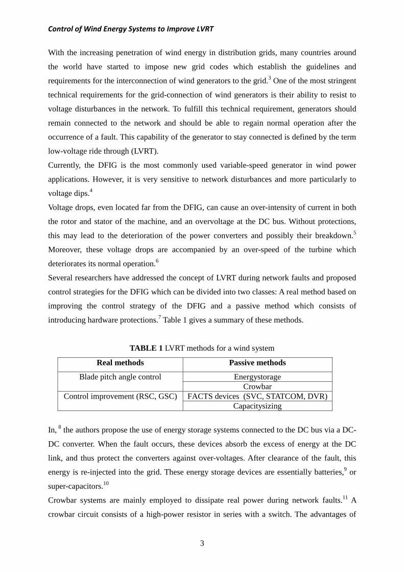
Several researchers have addressed the concept of LVRT during network faults and proposed
control strategies for the DFIG which can be divided into two classes: A real method based on
improving the control strategy of the DFIG and a passive method which consists of
introducing hardware protections.7 Table 1 gives a summary of these methods.
TABLE 1 LVRT methods for a wind system
Real methods Passive methods
Blade pitch angle control Energystorage Crowbar
Control improvement (RSC, GSC) FACTS devices (SVC, STATCOM, DVR) Capacitysizing
In, 8 the authors propose the use of energy storage systems connected to the DC bus via a DC-
DC converter. When the fault occurs, these devices absorb the excess of energy at the DC
link, and thus protect the converters against over-voltages. After clearance of the fault, this
energy is re-injected into the grid. These energy storage devices are essentially batteries,9 or
super-capacitors.10
Crowbar systems are mainly employed to dissipate real power during network faults.11 A
crowbar circuit consists of a high-power resistor in series with a switch. The advantages of

Control of Wind Energy Systems to Improve LVRT
4
this structure are its low cost and simplicity of its control structure. However, crowbar
systems cannot improve the injection of reactive power to the grid.
FACTS (Flexible AC Transmission Systems) are another option for keeping wind systems
connected to the grid in case of a fault. Examples of these are the STATCOM (Static
Compensator) and the SVC (Static Var Compensator). In general, they are used to increase the
reactive power control capacity.12 Another device is the DVR (Dynamic Voltage Restorer)
which works by injecting a compensating voltage through a transformer to support the grid
during a voltage dip.13 All these methods are based on the addition of hardware devices which
increase the total cost of the system. Alternatively, other works have focused on modifying
converter control strategies.
For the real LVRT methods, different control approaches have been proposed. In,14 the authors
studied the performance limits of vector control. Direct torque control, direct power control,
adaptive control and predictive control were also investigated.15-18
Most variable-speed wind turbine systems use vector control, which can be modified to meet
the LVRT requirements of grid operators. The authors in19 proposed a modified vector control
scheme by introducing the variation of flux in the coupling terms between the d-and q-axes.
This control approach was further extended to include both the flux magnitude and phase
angle, 20 and in, 21 an improved version of this control scheme was proposed.
Other more advanced control strategies have also been proposed to overcome the limitations
of classical proportional and integral (PI) controllers. Among these, sliding mode control, 22
second-order sliding mode control,23 fuzzy type-2 control,24 fuzzy control tuning by genetic
algorithms,25 fuzzy second order integral terminal sliding mode control,26 passivity control,27
and backstepping control.28
To sum up, whichever the method used, for the wind turbine to fulfill the LVRT requirements,
three physical quantities must be closely controlled during a voltage dip to prevent their
protections to trigger. These quantities are: the rotational speed of the generator, the stator and
rotor currents, and the DC bus voltage. The LVRT capability requires that the wind turbine
system must be able to limit, store and/or dissipate real power and contribute to restore the
voltage by injecting reactive power.
The authors in,29 presented a comprehensive review of the existing methods and future trends
of the DFIG in compliance with LVRT requirements. They concluded that if RSC can counter
the grid disturbance effect then the use of additional hardware such as crowbar, DC chopper,
etc. can be avoided. They finally suggested to focus more on the development of robust
nonlinear control techniques.

Control of Wind Energy Systems to Improve LVRT
In all these previous works, the authors assumed that the flux in the stator is constant in
amplitude to simplify the design of their controllers. However, dur
stator is directly connected to the network, the stator flux is expected to decrease. Therefore,
neglecting the dynamics of the stator flux may deteriorate the transient performance of the
system during fault conditions.
The solution proposed in this article is
the fault the real power is reduced,
return to its nominal value. The
reference values is based on F
controller is carried out considering
dip. The aim is to control the
to keep the electrical and mechanical quantities
dip.
This paper is organized as follows:
DFIG wind energy conversio
LVRT requirement. Section 3
control. The proposed FSMC contro
results and conclusion are presented
2. Problem Statement and P
The wind energy conversion system
depicted in Figure 1. The WECS power electronics interface with the
converters: the Rotor Side Converter
power of the DFIG and the Grid Side Converter (G
and reactive power exchanged with the network.
FIGURE 1 Wind energy conversion system based on a DFIG
Control of Wind Energy Systems to Improve LVRT
5
In all these previous works, the authors assumed that the flux in the stator is constant in
amplitude to simplify the design of their controllers. However, during a voltage dip, since the
stator is directly connected to the network, the stator flux is expected to decrease. Therefore,
neglecting the dynamics of the stator flux may deteriorate the transient performance of the
system during fault conditions.
roposed in this article is to re-adjust the references of the powers so that during
power is reduced, and the reactive power is injected to
The control scheme proposed to regulate the
Fuzzy Sliding Mode Control (FSMC) concept
considering the dynamics of the stator flux generated by the voltage
real and reactive powers of a DFIG-based wind turbine
the electrical and mechanical quantities above their threshold values
as follows: Section 2 describes the problems of the grid
wind energy conversion system during voltage dip, and presents the solution to the
Section 3 is devoted to the modeling of the system in view of the RSC
The proposed FSMC control scheme is derived in Section 4. Finally,
are presented in Section 5 and 6 respectively.
Proposed Solution
The wind energy conversion system (WECS) studied in this paper is based on a
The WECS power electronics interface with the gr
Rotor Side Converter (RSC) for the control of the real
Grid Side Converter (GSC) for the control of
exchanged with the network.
Wind energy conversion system based on a DFIG
In all these previous works, the authors assumed that the flux in the stator is constant in
ing a voltage dip, since the
stator is directly connected to the network, the stator flux is expected to decrease. Therefore,
neglecting the dynamics of the stator flux may deteriorate the transient performance of the
the references of the powers so that during
to help the voltage
regulate the powers to their
ontrol (FSMC) concept. The design of the
the dynamics of the stator flux generated by the voltage
wind turbine system
values during a voltage
of the grid-connected
nts the solution to the
is devoted to the modeling of the system in view of the RSC
nally, the simulation
studied in this paper is based on a DFIG and is
grid consists of two
and reactive stator
the DC bus voltage
Wind energy conversion system based on a DFIG.
Control of Wind Energy Systems to Improve LVRT
6
Under normal operating conditions, the generated electrical power " # is equal to the power
recovered by the turbine $ (when losses are neglected). Since the stator of the DFIG is
directly coupled to the grid, if a fault such as a voltage dip occurs, the generator magnetic
field and rotational speed will be directly affected and consequently this will limit the power
transmitted to the grid. At the appearance of the voltage dip, the power captured by the turbine
will be greater than the power transmitted to the grid. This causes an over-intensity of current
in both the rotor and stator in order to compensate for the decrease in the power caused by the
voltage dip.
The problem lies in the management of the excess power & $ " # inside the system.
To ensure that the LVRT is fulfilled, this excess of power must not cause any electrical and
mechanical quantities of the DFIG to drift above their threshold values and trigger the
protection.
To protect the system during voltage dips, grid operators in several countries request that the
real power injected by wind turbines into the electricity grid should be reduced to maintain the
stability of the system. In addition, the WECS should be able to supply the required amount of
reactive power to help restore the voltage to its nominal value.
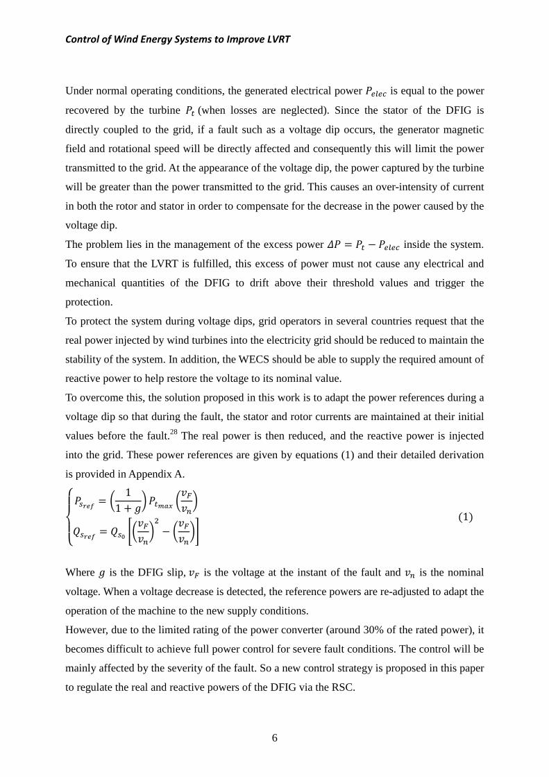
To overcome this, the solution proposed in this work is to adapt the power references during a
voltage dip so that during the fault, the stator and rotor currents are maintained at their initial
values before the fault.28 The real power is then reduced, and the reactive power is injected
into the grid. These power references are given by equations (1) and their detailed derivation
is provided in Appendix A.
'()(* +,- . 11 / 01 $234 .561
+,- 7 8.561 .5619 :1;<
Where 0 is the DFIG slip, 5 is the voltage at the instant of the fault and 6 is the nominal
voltage. When a voltage decrease is detected, the reference powers are re-adjusted to adapt the
operation of the machine to the new supply conditions.
However, due to the limited rating of the power converter (around 30% of the rated power), it
becomes difficult to achieve full power control for severe fault conditions. The control will be
mainly affected by the severity of the fault. So a new control strategy is proposed in this paper
to regulate the real and reactive powers of the DFIG via the RSC.

Control of Wind Energy Systems to Improve LVRT
7
3. Proposed modeling approach for the RSC controller design
Unlike other research studies which consider the flux in the stator constant in amplitude to
simplify the control design methodology, the approach proposed in this paper considers the
dynamic of the flux during the transients. During a voltage dip, the stator flux will decrease
because the stator is directly connected to the network and this should be taken into
consideration during the design of the controller.
In a rotating Park reference frame, the direct and quadrature components of the DFIG voltage
and flux are expressed as:
'((()(((* / ==> ?
? ? / =?=> / / ==> ?? ? / =?=> /
< :2;
')* / ? ? / ? / ? ? / ?
< :3;
The stator real and reactive powers are given by:
B / ? . ? ? . ? < :4;
It should be noted that the quadrature component of the flux is not equal to zero during a
voltage dip, hence the stator currents are obtained as:
')* ? ? ?
< :5;
Substituting these currents equations into (3):
')* /
? ? / ?< :6;
Now, substituting the flux equations into (2) yields:

Control of Wind Energy Systems to Improve LVRT
8
'()(* / ==> ? ? /
==>? ? / =?=> / / / =?=>
< :7;
Using equations (4) and (7) the following relationships between the stator powers and the
rotor voltages are obtained:
')* H? I IJ?K L 1 / :;M . . ? 1N / ?? /
H / I? / IJK L 1 / :;M . . ? 1N / ? ?< :8;
Where I and I? are the coupling terms between axes d and q. IJ and IJ? are related to the
stator flux and its dynamics. These terms are defined by:
BI I? ? <'()(*IJ .? ==> 1
IJ? . / =?=> 1< :9;
To control the powers of the DFIG at the desired references, equations (8) must be reproduced
in the opposite direction by imposing rotor voltages on the machine (?,). But these
equations show that there is a strong coupling between the powers and voltages. Therefore,
the control must be designed to compensate for the coupling effect, the variation of rotor
speed, the stator flux and the dynamics of the flux. To achieve this, each axis component must
be controlled independently i.e. each having its own control loop (power controller and rotor
current controllers).
4. Fuzzy Sliding Mode Control
A type of robust control law, simple to calculate and implement, even for nonlinear systems,
is sliding mode control. However, once the sliding regime is reached, the discontinuity in the
control generates high frequency oscillations, known as chattering. This is a major
shortcoming in sliding mode control, as it can lead to imprecise control, and generate noise in
the system.30 To eliminate this chattering phenomenon while retaining the robustness and
performance, the discontinuous component is replaced by a fuzzy logic structure.31
In general, to achieve this type of control two steps must be performed: choice of the sliding
surface and the synthesis of the control laws.
4.1. Choice of the sliding surface

Control of Wind Energy Systems to Improve LVRT
9
The choice of the sliding surface concerns not only the necessary number of these surfaces,
but also their shapes depending on the application and the intended purpose. Generally, the
number of sliding surfaces is chosen equal to the size of the control system.
To apply this control scheme to the DFIG, four sliding surfaces must be selected to control the
real and reactive powers as well as the rotor currents. These surfaces are selected according to
the error between the references input signals and the measurement signals.32
The most commonly used surface to obtain the sliding regime and which guarantees the
convergence of the state towards its reference is defined by 33:
Q:; : ==> / ;6RS I :10;
Where I U .
If IS, I, IV and IW denote the errors of the real power, reactive power, quadrature and direct
rotor currents respectively, then:
XISIIVIWY
Z[[[\ +,- +,- ?+,- ?+,- ]
_ :11;
Let ! 1 in (10), then the control surfaces have the following form:
Z[[\ Q:;Q:;Q:?;Q:;]
_ Z[[[\ +,- +,- ?+,- ?+,- ]
_ :12;
4.2. Synthesis of the control laws
The control action is designed to bring the errors IS,I ,IV and IW to zero under any parameter
uncertainties and grid disturbances conditions.
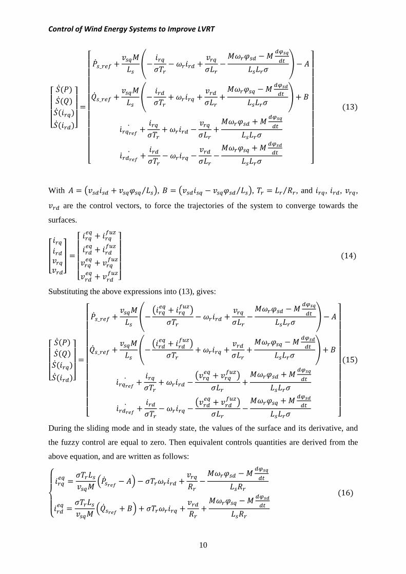
Substituting for , , taking the derivatives of the surfaces and finally substituting the
expressions of the currents `a?a and `aa from the equations of the voltages ? and
respectively, gives:
Control of Wind Energy Systems to Improve LVRT
10
Z[[[\ Qa:;Qa:;Qa:?;Qa:;]
_
Z[[[[[[[[[[[\ a_ U / ? c ? / ? Jde$ f ga_ U / ? c / ? / / ? Jdh$ f / i
`a?+,-a / ? / ? / / Jde$`a+,-a / ? ? / Jdh$ ]
^^^_
:13;
With g j / ?? ⁄ k, i j? ? ⁄ k, ⁄ , and ?, , ?, are the control vectors, to force the trajectories of the system to converge towards the
surfaces.
X ??Y
Z[[[[\
? ? / ?Ulm ? / Ulm? ? / ?Ulm
? / Ulm ]^_ :14;
Substituting the above expressions into (13), gives:
Z[[[\ Qa:;Qa:;Qa:?;Qa:;]
_
Z[[[[[[[[[[[\ a_ U / ? c j? ? / ?Ulmk / ? Jde$ f ga_ U / ? c j ? / Ulmk / ? / / ? Jdh$ f / i
`a?+,-a / ? / j? ? / ?Ulmk / / Jde$`a+,-a / ? j ? / Ulmk ? / Jdh$ ]
^^^_
:15;
During the sliding mode and in steady state, the values of the surface and its derivative, and
the fuzzy control are equal to zero. Then equivalent controls quantities are derived from the
above equation, and are written as follows:
'()(* ? ? ? na+,- go / ? Jde$
? ? na+,- / io / ? / / ? Jdh$< :16;

Control of Wind Energy Systems to Improve LVRT
'()(*? ? .`a?+,-a / ? /
? .`a+,-a / During the convergence mode, for the condition
must hold:
Z[[[\ Qa:;Qa:;Qa:?;Qa:;]
_ Z[[[[[[[\ ? ?Ulm ? Ulm 1 ?Ulm 1 Ulm ]
^^_
For the input variables (sliding surfaces of
currents and ?) and for
defined as: NB (Negative Big
Medium), and PB (Positive Big
FIGURE 2
FIGURE 3 Membership functions for
Control of Wind Energy Systems to Improve LVRT
11
1 / / Jde$?1 ? / Jdh$
< During the convergence mode, for the condition Q:;Qa:; p 0 to be satisfied
]^^_
input variables (sliding surfaces of the real power , reactive power
for the output variables (?Ulm , Ulm, ?Ulm , Ulm), the fuzzy sets
ig), NM (Negative Medium), EZ (Equal Z
ig) and are shown in Figures 2 and 3.
Membership functions for the input variables
Membership functions for the output variables.
:17;
satisfied, the following
:18;
reactive power and rotor
), the fuzzy sets are
), EZ (Equal Zero), PM (Positive
put variables.
variables.

Control of Wind Energy Systems to Improve LVRT
The fuzzy rules are given in
aggregation uses the max operator. The defuzzification of the control output is
center of gravity method.
TABLE
According to the rules presented in Table 2
and based on equation (18), it can be
imposes a positive output, hence the derivative of the surface is negative,
convergence condition is guaranteed
controller imposes a negative output, hence the derivative of the surface i
the convergence condition is achieved
Figure 4 shows the overall structure of the proposed control scheme.
FIGURE 4 Block diagram of the proposed control system
Fuzzy input
Fuzzy output
Control of Wind Energy Systems to Improve LVRT
12
Table 2. Mamdani’s fuzzy inference and membership function
the max operator. The defuzzification of the control output is
TABLE 2 Fuzzy rule base of the FSMC.
o the rules presented in Table 2 and the membership functions of
it can be noticed that if the surface is positive the fuzzy controller
oses a positive output, hence the derivative of the surface is negative,
guaranteed. Alternatively, if the surface is negative, the fuzzy
controller imposes a negative output, hence the derivative of the surface is positive,
achieved.
shows the overall structure of the proposed control scheme.
Block diagram of the proposed control system
NB NM EZ PM
NB NM EZ PM
embership function
the max operator. The defuzzification of the control output is based on the
the membership functions of Figures 2 and 3,
that if the surface is positive the fuzzy controller
oses a positive output, hence the derivative of the surface is negative, and therefore the
if the surface is negative, the fuzzy
s positive, and again
Block diagram of the proposed control system.
PB
PB

Control of Wind Energy Systems to Improve LVRT
13
5. Simulation Results
A simulation study is presented to validate the proposed control approach and demonstrate its
robustness and performance during voltage dips. The simulation is based on a 3 MW wind
turbine, the parameters of the DFIG and turbine models are listed in Table 3.34 These results
are compared with classical vector control.
TABLE 3 DFIG and turbine parameter values.34
6 q6 6 6
nominal power (MW) nominal voltage (V) nominal frequency (Hz) nominal wind speed (m/s) pole pairs
3 690 50 13 2 stator resistance (mΩ) 2.97 stator inductance (mH) 12.241 rotor resistance (mΩ) 3.82 rotor inductance (mH) 12.1773 mutual inductance (mH) 12.12 turbine total inertia (kg·m2) 254
#t u
turbine total friction coefficient (Nm·s/rad) nominal dc-link voltage (V) dc bus capacitor (F)
0.0024 1200 0.038 radius of the blades (m) 45
The simulated LVRT conditions for the wind turbine are as follows:
- The wind turbine must be operating at a critical threshold level before the fault. It
should be noted that these are the conditions under which the LVRT requirement is the
most difficult to fulfill, because the wind turbine operates at its maximum power and
its speed is in the super-synchronous mode.
- Before the fault; the real power injected into the grid is maximum, and the reactive
power is zero (unity power factor).
- During the fault, the real power is reduced, and the reactive power is injected into the
grid.
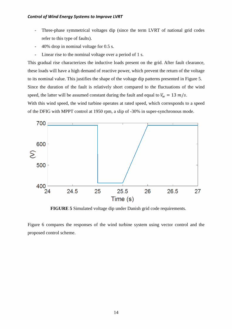
The voltage dip considered in this study has been inspired from Danish grid code. It is
illustrated in Figure 5 and has the following characteristics:
Control of Wind Energy Systems to Improve LVRT
- Three-phase symmetrical
refer to this type of faults)
- 40% drop in nominal voltage for 0.5
- Linear rise to the nomi
This gradual rise characterizes
these loads will have a high demand
to its nominal value. This justifies the shape of the voltag
Since the duration of the fault is
speed, the latter will be assumed
With this wind speed, the wind turbine operates at rated speed, which corresponds to a speed
of the DFIG with MPPT control at 1950 rpm, a slip of
FIGURE 5 Simulated voltage dip
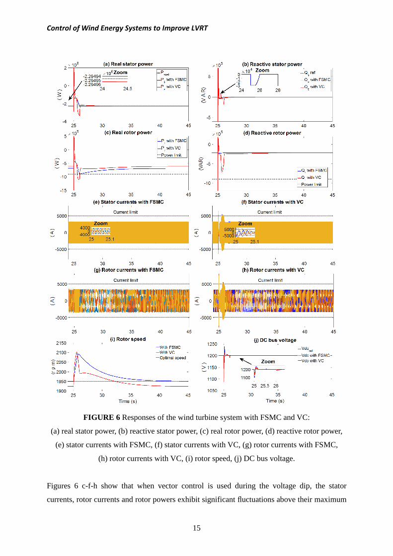
Figure 6 compares the responses of the
proposed control scheme.
Control of Wind Energy Systems to Improve LVRT
14
symmetrical voltages dip (since the term LVRT of national grid codes
refer to this type of faults).
drop in nominal voltage for 0.5 s.
ominal voltage over a period of 1 s.
characterizes the inductive loads present on the grid. After
have a high demand of reactive power, which prevent the return of the voltage
ustifies the shape of the voltage dip patterns presented in Figure
Since the duration of the fault is relatively short compared to the fluctuation
assumed constant during the fault and equal to the wind turbine operates at rated speed, which corresponds to a speed
MPPT control at 1950 rpm, a slip of -30% in super-synchronous mode.
Simulated voltage dip under Danish grid code requirements
he responses of the wind turbine system using vector
(since the term LVRT of national grid codes
After fault clearance,
the return of the voltage
e dip patterns presented in Figure 5.
luctuations of the wind 13 v/M.
the wind turbine operates at rated speed, which corresponds to a speed
synchronous mode.
Danish grid code requirements.
vector control and the
Control of Wind Energy Systems to Improve LVRT
FIGURE 6 Responses
(a) real stator power, (b) reactive stator power, (c) real rotor power, (d)
(e) stator currents with FSMC, (f) stator currents with VC,
(h) rotor currents with VC, (i) rotor speed, (j) DC bus voltage.
Figures 6 c-f-h show that w
currents, rotor currents and rotor powers
Control of Wind Energy Systems to Improve LVRT
15
Responses of the wind turbine system with FSMC and VC
(a) real stator power, (b) reactive stator power, (c) real rotor power, (d) reactive rotor power,
(e) stator currents with FSMC, (f) stator currents with VC, (g) rotor currents with FSMC,
(h) rotor currents with VC, (i) rotor speed, (j) DC bus voltage.
when vector control is used during the voltage d
rotor powers exhibit significant fluctuations above
FSMC and VC:
reactive rotor power,
(g) rotor currents with FSMC,
(h) rotor currents with VC, (i) rotor speed, (j) DC bus voltage.
control is used during the voltage dip, the stator
above their maximum

Control of Wind Energy Systems to Improve LVRT
16
acceptable limits (the currents limit is 150% of its rated value, and the rotor powers limit is
30% of its rated value). This will activate the protections so that neither the converter nor the
DFIG will be damaged, and it leads to the disconnection of the system. The excursions of the
responses of the current and rotor powers are due to the poor tracking of stator powers
references (Figures 6 a-b).
On the other hand, when the FSMC is used, the stator powers follow their references perfectly
(Figures 6 a-b). The stator and rotor currents are maintained constant as shown in Figures 6 e-
g. In addition the rotor powers do not exceed their limits (Figures 6 c-d).
During the fault, the power from the wind is stored as kinetic energy in the rotor (due to its
large inertia, the rotor of the wind turbine has a capacity to store energy).25 This causes an
increase in the rotor speed (≈2100 rpm). Note that this increase is about 40% above the speed
of synchronism (1500 rpm) for both control strategies (Figure 6i). For this type of wind
turbine the increase in speed is acceptable, since it has a short duration. However if the speed
is compared with the speed before fault, an increase of about 9.25% can be observed in the
case of VC, and 7.3% in the case of FSMC. This is explained by the fact that with VC the
speed is not optimal in the nominal regime, because there is a slight steady-state error in the
stator active power as shown in the zoom of Figure 6a.
After fault clearance, the energy stored in the rotor is sent to the grid as active power and
subsequently, the rotor speed gradually returns back to its pre-fault value. It can be observed
that FSMC leads to a better performance as compared to VC.
The DC bus voltage waveform is shown in Figure 6j. At the onset of the fault, the rotor power
demand will be supplied from the DC link, this results in a decrease of the DC bus voltage.
When the fault is cleared, this voltage undergoes a disturbance and then is subsequently
regulated via the GSC and maintained within an acceptable level.
From these results, it can be noted that with the FSMC there is a good tracking of the
reference powers which significantly improve the behavior of the system during dip voltage.
The proposed control design strategy was based on wind turbine model parameters which
have been assumed fixed. However, in a real system, such as the wind generator, these
parameters are subject to variations due to different physical phenomena such as saturation of
inductances, heating of resistors, etc.
Therefore, testing the robustness of the controller under parameter uncertainties is essential.
This test is carried out by varying the DFIG model parameters. The resistances are increased
by 50%, and the inductances are decreased by 50%. The responses of the real and reactive

Control of Wind Energy Systems to Improve LVRT
stator powers under parameter
good tracking of the real and reactive powers
FIGURE 7 Responses of the real and reactive sta
(a) real stator power with FSMC, (b) real stator power with VC, (c) reactive stator power with
FSMC, (d) reactive stator power with VC
These results show that by adopting
hardware, the DFIG-based variable
requirements and remain connected during
level (if the voltage dip does not exceed 40% of the nominal voltage
The strategy for the adaptation of
ensures that the electrical and mechanical quantities
very much dependent on the performance of the control scheme
addressed via the application of FSMC which
flux.
6. Conclusion
The paper proposed a fuzzy sliding mode control (
dynamics of the stator flux in the
turbine during a voltage dip.
Control of Wind Energy Systems to Improve LVRT
17
er uncertainties are shown in Figure 7. The results demonstrate a
the real and reactive powers references when using FSMC.
esponses of the real and reactive stator powers under parameter
(a) real stator power with FSMC, (b) real stator power with VC, (c) reactive stator power with
FSMC, (d) reactive stator power with VC
y adopting the proposed control strategy without addi
based variable-speed wind turbine is able to fulfill the LVRT
main connected during voltage dips when operating at a critical threshold
f the voltage dip does not exceed 40% of the nominal voltage).
strategy for the adaptation of real and reactive powers references during voltage dips
electrical and mechanical quantities do not exceed their limits.
performance of the control scheme of the powers. This
the application of FSMC which takes into account the variation of the stator
fuzzy sliding mode control (FSMC) scheme that takes into account the
in the control of real and reactive power of a DFIG
. The results demonstrate a
FSMC.
under parameter uncertainties:
(a) real stator power with FSMC, (b) real stator power with VC, (c) reactive stator power with
control strategy without additional
is able to fulfill the LVRT
at a critical threshold
during voltage dips
not exceed their limits. This strategy is
wers. This has been
the variation of the stator
that takes into account the
and reactive power of a DFIG-based wind

Control of Wind Energy Systems to Improve LVRT
18
The results demonstrate that FSMC provides a more robust control of the DFIG during the
voltage dip conditions as compared to vector control. Indeed, the DFIG was able to
successfully overcome the voltage dip without disconnecting from the network. The system
was able to quickly regain its initial state of operation.
It should be noted that with FSMC it is possible to improve the capacity of the DFIG to resist
against voltage disturbances so as to satisfy the constraints imposed by the LVRT
requirements without the need of any auxiliary hardware. However, its capacity is limited by
the relatively small size of the power converters.
Appendix A: Calculation of powers references (equation (1))
Under normal conditions, the real and reactive stator powers are expressed as:
'()(* 6 6 ?6
6 6 6 6 :19;<
And in the case of fault, these powers are given as:
'()(*5 5 ?5
5 5 5 5< :20;
To have a power adjustment during the voltage dip, it is necessary that the rotor currents are
maintained at the same levels as before fault, i.e. ?6 ?5 and 6 5
For this, the following equalities must hold:
'()(* 6 6 5 56 x 6 6y 6 x 5 5y< :21;
Thus the relation between the powers before and during the default is given as follows:
'()(* 5 6 .561
5 6 .561 / 6 8.561 .5619< :22;
In our study the stator real power is controlled so that the DFIG converts the maximum of the
available mechanical power from the turbine such as; if the losses are neglected, the converted
real power is expressed by: $ / / 0 :1 / 0; :23;

Control of Wind Energy Systems to Improve LVRT
The stator reactive power is controlled so that the reactive power is zero (
Therefore, the references of the
'()(* +,- . 11 / 01 $234 .561
+,- 7 8.561 .5619With 7 6 ⁄
It should be noted that when the
term z:5 6⁄ ; :5 6⁄ ; reset to their values before the fault.
Appendix B: Determination of the PI controllers parameters.
In the control of the RSC, four controllers were used: two for th
currents. To simplify the design of the controllers,
terms are neglected. Then, it can be
are identical and hence the controllers for the two loops are the same.
The block diagram of the closed
FIGURE 8 Control block diagram in the
Figure 8 shows two control loops
external loop for the control of the power
the current loop, a 1st order closed
2nd order closed-loop transfer function
The open-loop transfer function of the current
|~+e / ~~+eM 1 / M After calculation and identification, the
Control of Wind Energy Systems to Improve LVRT
19
reactive power is controlled so that the reactive power is zero (ences of the stator powers are written as equation (1)
. 1. 19 <
uld be noted that when the fault is cleared, the ratio :5⁄ 0, hence the reference values of real and reactive power are
reset to their values before the fault.
Determination of the PI controllers parameters.
In the control of the RSC, four controllers were used: two for the powers and
To simplify the design of the controllers, the RSC is assumed ideal
Then, it can be noticed that the transfer functions of the two
and hence the controllers for the two loops are the same.
The block diagram of the closed-loop axis control of the RSC is depicted in Figure 8.
Control block diagram in the axis of the RSC.
ntrol loops: an internal loop for the control of the current and an
control of the power. For the calculation of the controller parameters of
closed-loop transfer function is used. For the power control l
function is used.
loop transfer function of the current control loop is given by:
1M After calculation and identification, the following PI controller parameters
6 0).
:24;
6⁄ ; 1 and the
and reactive power are
e powers and two for the rotor
assumed ideal and the coupling
the transfer functions of the two = and axes
depicted in Figure 8.
axis of the RSC.
an internal loop for the control of the current and an
For the calculation of the controller parameters of
power control loop, a
:25;
are obtained:

Control of Wind Energy Systems to Improve LVRT
20
'()(*~+e 3>~+e 0.0053
~~+e 3>~+e 0.1146 < :26; >~+e is the settling time of the closed-loop response of the current.
Similarly, for the power control loop, the closed-loop transfer function is given as follows:
:M; nddoddM / dddd M / ddd :27;
The controller parameters are obtained using a simple pole placement. The desired
characteristic polynomial is written as follows: M / 2M / 2.
After calculation and identification, the following PI controller parameters are obtained:
'()(*d 2 0.006
~d 2 0.56 < :28;
References
1. American National Standard (ANSI). IEEE Recommended practices and requirements
for harmonic control in electrical power systems. IEEE Std 519. 1992.
2. Bollen MHJ. Understanding power quality problems voltage sags and interruptions.
New Jersey: John Wiley & Sons; 2000.
3. Mohseni M, Islam SM. Review of international grid codes for wind power integration:
diversity, technology and a case for global standard. Renewable and Sustainable
Energy Reviews. 2012; 16(6):3876-3890.
4. Rolán A, Pedra J, Córcoles F. Detailed study of DFIG-based wind turbines to
overcome the most severe grid faults. Electrical Power and Energy Systems. 2014;
62:868-878.
5. Gayen PK, Chatterjee D, Goswami SK. An improved low-voltage ride-through
performance of DFIG based wind plant using stator dynamic composite fault current
limiter. ISA Transactions. 2016;62: 333-348.
6. Oriol GB, Adrià JF, Sumper A, Joan B-J. Ride-through control of a doubly fed
induction generator under unbalanced voltage sags. IEEE Transactions On Energy
Conversion. 2008; 23(4):1036-1045.
Control of Wind Energy Systems to Improve LVRT
21
7. J. J. Justo, F. Mwasilu, and J.-W. Jung. Doubly-fed induction generator based wind
turbines: A comprehensive review of fault ride-through strategies. Renewable and
Sustainable Energy Reviews. 2015; 45: 447-467.
8. I. Ngamroo and T. Karaipoom. Cooperative Control of SFCL and SMES for
Enhancing Fault Ride Through Capability and Smoothing Power Fluctuation of DFIG
Wind Farm. IEEE Transactions on Applied Superconductivity. 2014; 24(5):1-4.
9. K. Ibrahima and C. Zhao. Modeling of wind energy conversion system using doubly
fed induction generator equipped batteries energy storage system. 4th International
Conference on Electric Utility Deregulation and Restructuring and Power
Technologies (DRPT), 2011; 1780-1787.
10. S. I. Gkavanoudis and C. S. Demoulias. A combined fault ride-through and power
smoothing control method for full-converter wind turbines employing Supercapacitor
Energy Storage System. Electric Power Systems Research. 2014; 106: 62-72
11. G. Pannell, D. J. Atkinson, and B. Zahawi. Minimum-Threshold Crowbar for a Fault-
Ride-Through Grid-Code-Compliant DFIG Wind Turbine. IEEE Transactions on
Energy Conversion. 2010; 25(3):750-759.
12. M. Molinas, J. A. Suul, and T. Undeland. Low Voltage Ride Through of Wind Farms
With Cage Generators: STATCOM Versus SVC. IEEE Transactions on Power
Electronics. 2008; 23(3): 1104-1117.
13. C. Wessels, F. Gebhardt, and F. W. Fuchs. Fault Ride-Through of a DFIG Wind
Turbine Using a Dynamic Voltage Restorer During Symmetrical and Asymmetrical
Grid Faults. IEEE Transactions on Power Electronics. 2011; 26(3): 807-815.
14. Xiang D, Ran L, Tavner PJ, Yang S. Control of a doubly fed induction generator in a
wind turbine during grid fault ride-through. IEEE Transactions On Energy
Conversion. 2006;21:652-662.
15. Seman S, Niiranen J, Arkkio A. Ride-through analysis of doubly fed induction wind-
power generator under unsymmetrical network disturbance. IEEE Transactions On
Power Systems. 2006;21:1782-1789.
16. Nian H, Song Y, Zhou P, He Y. Improved direct power control of a wind turbine
driven doubly fed induction generator during. IEEE Transactions On Energy
Conversion. 2011;26:976-986.
17. Song Z, Shi T, Xia C, Chen W. A novel adaptive control scheme for dynamic
performance improvement of DFIG-Based wind turbines. Energy. 2012;38:104-117.

Control of Wind Energy Systems to Improve LVRT
22
18. Phan VT, Lee HH. Improved predictive current control for unbalanced stand-alone
doubly-fed induction generator-based wind power systems. IET Electric Power
Applications. 2011;5:275-287.
19. Peng L, Colas F, Francois B, Li Y. A modified vector control strategy for DFIG based
wind turbines to ride-through voltage dips. 13th European Conference on Power
Electronics and Applications, 2009.
20. Anaya-lara O, Hughes FM, Jenkins N, Strbac G. Rotor flux magnitude and angle
control strategy for doubly fed induction generators. Wind Energy. 2006;9:479-495.
21. Xiao-ming Li, Xiu-yu Zhang, Zhong-wei Lin, Yu-guang Niu. An Improved Flux
Magnitude and Angle Control With LVRT Capability for DFIGs. IEEE Transactions
on Power Systems. 2018
22. Saad NH, Sattar AA, Mansour AEM. Low voltage ride through of doubly-fed
induction generator connected to the grid using sliding mode control strategy.
Renewable Energy. 2015;80:583-594.
23. Benbouzid M, Beltran B, Amirat Y, Yao G, Han J, Mangel H. Second-order sliding
mode control for DFIG-based wind turbines fault ride-through capability
enhancement. ISA Transactions. 2014;53:827-833.
24. Raju SK, Pillai GN. Design and real time implementation of type-2 fuzzy vector
control for DFIG based wind generators. Renewable Energy. 2016;88:40-50.
25. Theodoros DV, Xanthi IK, Nicholas AV. A genetic algorithm-based low voltage ride-
through control strategy for grid connected doubly fed induction wind generators.
IEEE Transactions On Power Systems. 2014; 29(3):1325-1334.
26. Mohammad JM, Afef F. A new fault ride-through control for DFIG-based wind energy
systems. Electric Power Systems Research. 2017; 146: 258-269.
27. Vandai L, Xinran L, Yong L, Tran LTD, Caoquyen L. An innovative control strategy to
improve the fault ride-through capability of DFIGs based on wind energy conversion
systems. Energies. 2016; 69(9):1-23.
28. Kammoun S, Sallem S, Kammoun MBA. Backstepping control for low-voltage ride
through enhancement of DFIG-based wind turbines. Arabian Journal for Science and
Engineering. 2017; 42(12):5083-5099.
29. M. Ezzat, M. Benbouzid, S. M. Muyeen, and L. Harnefors, “Low-voltage ride-through
techniques for DFIG-based wind turbines: state-of-the-art review and future trends,” in
IECON 2013 - 39th Annual Conference of the IEEE Industrial Electronics Society.
2013; 7681–7686.

Control of Wind Energy Systems to Improve LVRT
23
30. Furat M, Eker Đ. Second-order integral sliding-mode control with experimental
application. ISA Transactions. 2014;53:1661-1669.
31. Ardjoun SAEM, Abid M. Fuzzy sliding mode control applied to a doubly fed
induction generator for wind turbines. Turkish Journal of Electrical Engineering &
Computer Sciences.2015;23(6): 1673-1686
32. Utkin VI. Sliding mode control design principles and applications to electric drives.
IEEE Transactions On Industrial Electronics. 1993;40:23–36.
33. SLOTINE J-JE, LI W. Applied Nonlinear Control. Englewood Cliffs New Jersey:
Prentice Hall; 1991.
34. Lohde R, Jensen S, Knop A, Fuchs FW. Analysis of three phase grid failure and
Doubly Fed Induction Generator ride-through using crowbars. Proceedings of the 12th
European Conference on Power Electronics and Applications (EPE 2007), Aalborg,
Denmark, September 2007.