a review on computational electromagnetics methods · accuracy by using cst microwave studio® and...
TRANSCRIPT

A review on Computational Electromagnetics Methods
P. Sumithra1 * and D. Thiripurasundari 2
1, 2 School of Electronics Engineering, VIT University, Vellore, Tamil Nadu 632014, India
*Corresponding author: Sumithra. P, E-mail: [email protected]
Abstract
Computational electromagnetics (CEM) is applied to model the interaction of electromagnetic fields with the objects like antenna, waveguides, aircraft and their environment using Maxwell equations. In this paper the strength and weakness of various computational electromagnetic techniques are deliberated in detail. Performance of various techniques in terms accuracy, memory and computation time for application specific tasks such as modeling RCS (Radar Cross Section), space Applications, thin wires and antenna arrays are presented in this paper. Commercial software codes has certain limitations, Agilent ADS could not model 3D structures, HFSS is accurate but execution time is h igh, WIPL-D® does not support modeling Inhomogeneous dielectrics embedded metal objects and periodic structures. IE3D® is not suited for geometry with fin ite details. However for regular shapes like rectangular patch MOM based IE3D provides accurate results than FEM based IE3D. The complicated structures are dealt with accuracy by using CST Microwave Studio® and HFSS®. Although CST and HFSS has similar interface in dealing with geometry with fine details, CST had edge over HFSS software as it starts in time domain and ends in frequency domain. HFSS uses Finite Element Method (FEM) to arrive at frequency domain solution. FEKO® has two main solvers MOM based and GTD based. GTD based FEKO is good in handling large structures like reflector antennas.
1. Introduction
The Widespread use of antennas has spurred considerable attention to the computational analysis of electromagnetics The CEM techniques came into limelight after the introduction of three pillars of numerical analysis viz. FDTD (Finite Difference Time Domain) , FEM (Finite Element Method) and MOM (Method of moments). Most EM problems ult imately involve solving only one or two partial differential equations subject to boundary constraints but a very few practical problems like modeling homogeneous, inhomogeneous problems and boundary value problem can be solved without the aid of a computer. Computational Electromagnetics techniques are flexible. CEM finds its application in fields like design and analysis of RCS (Radar Cross Section), antenna geometry, bio medical applications, space borne radar and satellite applications, hand held devices, nano photonic devices and other communication devices.
CEM is used in solving EM compatibility problems and issues associated with them. Few issues like Multiscale model, macro-models, time-domain and frequency-domain models, the use of structured meshes, un-structured meshes and stochastic models in EM compatib ility are discussed in [1]. CEM is broadly classified into numerical methods, high frequency methods and other methods. The Numerical methods includes integral equation based MOM method, differential equation based FEM and FDTD. High frequency methods include current based Physical optics (PO) and fie ld based Geometric optics (GO). Other methods include Generalized Multipo le Technique (GTM), Transmission line matrix method (TLM) and modal methods (MM) to name a few. The computational h ierarchy of these methods is depicted in Figure.1. CEM practit ioners in the recent days are aiming to use existing software packages to solve a particular problem as early as possible. Present CEM researchers have limitation in learn ing the CEM methods, due to the readily available software packages. It is more important that experienced CEM researchers impart the knowledge and share the experience with young researchers. An attempt has been made in this paper to report on the growth and advancements in the field of computational electromagnetics.
Figure 1: Computational hierarchy
2. Survey of CEM
The growing field of CEM research has sprouted various divisions of research. CEM research is carried out mainly in three ways viz. (i) analytical techniques, (ii) numerical analysis technique, (iii) expert systems. Analytical
ADVANCED ELECTROMAGNETICS, VOL. 6, NO. 1, MARCH 2017

43
techniques make some assumptions (for example geometry like ground plane is considered as infinite ground plane) to get closed form solution (look up table). Analytical techniques are used not only in simple computer progra ms but also in elaborate IEMCAP (Intra system Electromagnetic Compatibility program) provided they have anticipation of EM interactions [2]. Analysis of numerical techniques plays a vital ro le in select ing suitable method for various geometries. Expert systems estimate values for the parameters of interest through their knowledge on EM interactions that cause EMI sources to radiate [3, 4]. Expert system is unsuitable for difficult EM problems. Prominent methods used in this domain of research are discussed to provide insight in to computational electromagnetics.
2.1. FDTD (Finite Difference Time Domain)
Yee et al defined FDTD scheme in the year 1966. He provided the solution to Maxwell’s curl equation involving centred finite difference approximations to find part ial space and time derivatives. Consider one component of Maxwell’s equation:
(
) (1)
Using the central difference scheme, the above equation is discretized. FDTD algorithm comprises a grid o f points containing computational domain, a stencil to approximate PDE, a boundary condition to approximate points on boundary of computational domain, an excitation source and solution method to solve PDE. Post processing is done to find physical quantities from field equations [5]. In 1980, Taflove created an acronym to refer to fin ite difference time domain schemes (FDTD). The computational domain of structure under analysis is discretised using two techniques viz.(i) Bergner’s PML (Perfectly Matched Layer) and (ii) Modified PML. The PML is illustrated as follows.
2.1.1. Perfectly Matched Layer (PML)
Mesh termination remains as problem in modelling the computational domain using FDTD. Reflection from boundary that arises due to coarse meshing affects accuracy of computation. Absorbing Boundary Conditions (ABC) demands larger computational domain to be meshed. Domain is large in ABC as they need adequate distance between radiating body and boundary. The ABC can achieve a return loss of -20 dB to -30 dB. However ABC need to battle to achieve return loss less than -50 dB [6] because ABC shows good performance in absorbing reflection only for normal angles and performance is poor for angles other than normal incidence [7]. This reflection is greatly reduced by making computational domain finite through domain truncation techniques. Truncation techniques experiences
the truncation error in cases wherever they are not properly implemented, therefore accuracy of computed results is affected. Computational resource requirement such as time and memory for high order ABC is high as computational domain is larger. The computational effort can be reduced and accuracy is enhanced by introducing an absorbing layer called Perfectly Matched Layer (PML). Berenger [8] introduced this method for 2D cases in 1994 by p lacing boundary close to radiating body. The E or H field is split into two and different E and H loss is assigned to each field component [7]. FDTD update equations are used by PML to accommodate these split fields. The layout of Perfectly Matched Layer is depicted in Figure 2. X-PML is X –oriented PML and Y- PML is Y oriented PML and X-Y PML is X-Y oriented PML. σx , σy are conductivities in X and Y direction. Corner reg ions are handled well by overlapping X and Y PML resulting in X-Y PML. Absorption of reflection with PML is good at all frequencies and angle of incidence regardless of polarization of angle of incidence [7]. Perfect matching is achieved by PML using absorbing materials with electric and magnetic losses at termination of mesh. PML uses two approaches namely stretched approach (mathemat ical in nature) and anisotropic media with Uniaxial PML (popular method) [6]. PML Techniques allows Electromagnetic waves to be absorbed with min imal reflection and further this reflection magnitude is decreased by fine tuning of parameters like thickness of layer [8] thereby achieving return loss greater than -100 dB [6] better than anechoic chamber (-70 dB). The PML requires more computational domain and CPU t ime due to the splitting of the fields which makes it unreliable.
4 X-Y PML σx , σy≠ 0
3 Y PML σx=0 , σy≠ 0
2 X-Y PML σx , σy≠ 0
5 X PML σx≠0 ,
σy= 0
Object for
Computation
1 X PML σx≠0 ,
σy= 0 6
X-Y PML σx , σy≠ 0
7 Y PML σx=0 , σy≠ 0
8 X-Y PML σx , σy≠ 0
Figure 2: Layout of Perfectly Matched Layer Further in FDTD d iscretization of computational domain poses error due to truncation. Staircase approximat ion also contributes error accumulat ion at each time step for surface with sharp and fine edges [9]. Also reflection error increases with increase in time step affecting accuracy of method.
Perfect Conductor

44
The reflection error could be reduced by placing non-resonant absorber adjacent resonating object (i.e.) Resonating Perfectly Matched Layer (RPML). Period ic structures could be analysed using this technique due to its capability, reduced computation domain of repetitive structures up to 70% for 1D objects and 90% for 2D objects [10]. Also, this method has good convergence. Courant, Friedrichs, Lewy discovered and named it as CFL limit in order to ease the solution of second order wave equation. Desired accuracy is obtained when time step is within CFL limit making the system unconditionally stable at the expense of computational t ime. The FDTD is solved by Zheng Yu Huang in [11] by a new unconditionally stable method using Associate Hermite (AH) function. In [11] Orthonormal basis function is used to expand the E field and time derivatives. Time variables associated with it is removed by Galerkin testing procedure. Here in [11] the CPU time is reduced by 0.59% than traditional FDTD without any impact on the accuracy at the cost of memory consumption. Spheroidal FDTD uses CFL limit and field formulas to deal with singularity at the center and edges of spherical cavit ies and patch antennas with addit ional computational cost than conventional FDTD [12]. An efficient 3D FDTD gives solution to Maxwell’s equation using two different time step increments. Applications like space weather effects, satellite communicat ions operating at high altitudes, high collisional regimes are analysed by this method. Easy implementation, less memory and time makes this method more attractive than anisotropic approach. However, stability is largely affected for strong electric field as error increases with increase in time step [13]. Semi Implicit Schemes (SIS) depend on current step alone, over ruling the dependence of CFL limit for applications involving larger time step. This method computes E and H field at each step, forcing the time step be within CFL limit. For computational domain problems requiring larger time step, this method is an ideal choice. This method is used when time step (> 10 t imes) is larger than FDTD stability limit at the cost of additional memory consumption. Memory storage and computational cost is proportional to the electrical size of geometry and grid resolution. Electrical properties of the scatterers are varied at each step by varying the values of µ, , and є assigned to each field component. SIS performs certain modification to CPML-FDTD enabling implementation of CFS-PML to resolve synchronisation issues in CPML-FDTD, RIPML that affects accuracy in cases like dispersive media. Further this CFS-PML requires less computation and memory in treating unbounded 2D region and thin bounded PEC [14]. An algorithm called sub-cell algorithm is used to model flat electrode using coarse grids of FDTD preserves 12% computational memory and 3% of CPU t ime usage than traditional FDTD without compromising efficiency [15]. Long and short apertures without depth or with finite depth
could be modelled using uniform two step method in FDTD analysis with good accuracy, high resolution in [16]. The two step uniform method is processed in steps like: (i) estimate aperture-field singularity using standard FDTD simulation at the edge of the receiver to yield aperture coefficients (ii) coefficients thus obtained are used in contour path to define FDTD update equations for fields near aperture. The challenges faced by this method are computational memory and accuracy. Fin ite Difference Time Domain – Alternating Direction Implicit Method (FDTD-ADI) d iscussed in [17] is an unconditionally stable method that operates in one step leap frog fashion to solve open region (isotropic lossless) problems using Sherman Morrison formula to solve tridiagonal equations efficiently. Also this method is efficient in terms of computation time, memory and similar accuracy in comparison with two step schemes. The main issues associated with this method are increase in error with increase in time. Locally One-Dimensional-Finite-Difference Time-Domain Method (LOD-FDTD) is found to be faster than parallel (FDTD-ADI) method, where parallelization is achieved using message passing interface. Debye-dispersive media, complex bio -electromagnetic problems like deep brain stimulat ion could be handled with good scalability and performance. LOD-FDTD ach ieves lower communications between cores (up to 40 cores) than FDTD-ADI, however suffers efficiency issues if number of cores goes beyond 40 cores [18]. Th is method uses less CPU time at the cost of memory consumption. In order to improve performance of conventional FDTD in terms of CPU time and memory, Zh i-Hong proposed in [19] a DD (Domain Decomposition)-Laguerre-FDTD method to solve very large rough surface, PEC, lossy dielectric media, large scatterers. The computational domain is discretised into sub domains, radiated and scattered fields. DD-FDTD can model vast rough region than conventional FDTD. Characteristic basis functions (CBFs) are employed to mitigate interpolation erro rs between the boundaries thereby increasing accuracy of this method. Min Zhu proposed in [20] a Novel RK-HO-FDTD (Runge Kutta Higher Order FDTD) used in computation of EM regions which is in terms of accuracy, speed, convergence and has reduced dispersion. This method combines SSP-RK and HO-FDTD. RK-HO-FDTD is pretty much attractive than HO-FDTD, MRTD and RK-MRTD methods due to its better scattering properties and quick convergence.
2.2. FEM (Finite Element Method)
FEM code meshes computational domain problem into sma ll portions and forms linear equations using weighted residual method and solves the same by reducing the energy of geometry viz. inhomogeneous material resonant cavities. Thin wires, large rad iation problem like Eigen value problem and 3D problems are difficult to be modelled using

45
FEM due to its unstructured mesh. FEM for 3D EM problems faces certain issues than 2D problems like need for excessive computation and vector parasites that results in false solutions. FEM is used in modelling Yagi-Uda antennas, horn antennas, waveguides, vehicular and conformal antennas [21]. Bangda Zhou proposed Direct FE solver [22] that uses the following algorithm: (i) Divid ing of unknown nested dissection (ii) Constructing elimination tree, (iii) Symbolic factorization (iv) H matrix creation for frontal matrix for every node of elimination tree (v) H matrix based algorithm to perform numerical factorization to arrive at the solution and (vi) post processing. Although this method is far better than the available commercial solvers for applications like 3D structures, Patch antennas , it is not ideal in terms of CPU time and memory storage. Dual Prime (FETI-DP) method in [23] incorporates Hierarchical-Lower Upper (H-LU) and Nested Dissection (ND) is a domain decomposition method. This solver with sub-domain finite element systems has faster convergence and numerical scalability without sacrificing efficiency. The applications of this method include 3D structure problem, periodic array problem, Jerusalem type array, Vivald i array. These applications use LU for maintain ing computation resources and accuracy while ND conforms less memory and CPU t ime. Though this method facilitate parameter choice based on applications, accuracy and computational cost for unconditionally s table system has a trade-off [24]. Ivan Voznyuk [25] discussed Finite - Element Tearing and interconnecting Full-Dual-Primal (FETI-FDP2) (FETI-FDP2) method an extended version of FETI-DPEM2 is used in analysis of 3D large-scale electromagnetic problems using robin type boundary condition at corners and interface. Electrically s mall problems are solved by using Krylov solver and ASP/AMG(Auxiallary Space Preconditioners / Algebraic Multigrid) preconditioners as they facilitate convergence with lesser iterations. However the implementation could be extended not only to geometry that is tedious to solve but also to electrically large problems using DDM [26]. The incapability of iterative solver to converge due to presence of PML is over ru led by Dirich let-to-Neumann (DtN) approximat ion [25]. Further, algorithm’s parallelization improves convergence. The use of Robin type boundary condition at interface cause the Interface issue, that is solved by an effective code based on mesh partitioning without affecting accuracy. This method requires performance enhancement in terms of memory and CPU time and is not suitable for hierarchical elements that are higher in order. Zhi-Qing Lü [27] proposed Non-Conforming FETI (NC-FETI). Few steps involves are (i) Computational domain is discretised to subdomain (ii) Data transfer between subdomains is done by imposing Robin type boundary condition (iii) Lagrange mult iplier scheme and Schur complement approach are used to solve interface issue and
(iv) Iterat ive algorithm is to find unknown electric field. NC-FETI is far better than DDM and is capable of modeling 3D large-scale slot array, complicated electromagnetic problems such as photonic band gap and antenna arrays with efficiency and accuracy at the cost of memory. Memory consumption can be greatly reduced for periodic structures due to their repetitive nature [27]. Jian Guan proposed an accurate and efficient Finite Element-Boundary Integral-Multilevel Fast Multipole Algorithm method (FE-BI-MLFMA) [28]. The formulation of FE-BI is first approximated by FEM with absorbing boundary condition. Further it is solved using FETI with numerical complexity and considerable scalability. The efficiency of this method is increased by Graphics Processing Unit (GPU) accelerated MLFMA. Testing schemes involved in this method are enhancing accuracy and ABC preconditioner improves speed by faster convergence of iterative solution. However ABC preconditioners like algebraic preconditioners demands bulky factorizat ion which is solved by DDM. In spite of parallelization difficu lty, this method is suitable in real applications like biomedical application involving human body, RCS, space applications involving missiles, antenna arrays due to its accuracy and efficiency. Ming Lin in [29] suggested that Domain Decomposition based Preconditioner - Finite Element-Boundary Integral-Multilevel Fast Multipole A lgorithm (DDP-FE-BI-MLFMA) is best for large lossy objects; it finds difficulty in dealing with 3D objects that are lossless with high µr and ԑr. CFL limit is having an important ro le in unconditional stability. Also semi implicit schemes could be used to attain memory and CPU time and cost reduction. GPU with Compute Unified Device Architecture (CUDA) quickens solution to mitigate parallelization blocks. GPU (Graphics Processing Unit) accelerated parallelization is done using ILU (Incomplete LU) preconditioner, SSOR preconditioner, Pard iso, MKL solver provided DDA speeds up large scale problem [30, 31]. This method holds good for fin ite element structures and single array with large structures due to the increased speed within less time, but complicated antenna and microwave devices are having difficulty in convergence.
2.3. MOM (Method of Moments)
Antenna structure is analyzed using MOM by splitting the computational area into various segments viz. meshing and evaluating each segment using basis functions. The selection of basis functions plays a vital role in arriving at the solution with accuracy, efficiency. Current distribution is decomposed with this basis function. Green’s functions help in studying current on each segment and strength of each moment. Accuracy of calculat ing integral of Green’s function is enhanced by employing singularity extract ion. In addition with accuracy in calculating self -interaction and near interaction matrix, the problem converges to finite solution with less number of iterations using singularity

46
extraction. MOM discretizat ion leads to very large and dense matrix, consumes more time making it not suited for large problems, this could be solved by using preconditioners and iterative methods [32]. MOM is capable of modeling thin wire structures with speed, accuracy, convergence and versatility using triangular basis functions. MOM, a pro jection based process that solves linear equations to find unknown current distribution requires the solution to be well conditioned and error controllable. To attain these targets we emphasis on an equation to have single solution conforming to discretizat ion and well-conditioned MOM matrix. However various issues associated with MOM like singularity, low-frequency breakdown and charge cancellation, non-smooth surfaces and physical resonances, composite structures, inhomogeneous and anisotropic medium, mult i-scale problems poses great difficulty in realizing these targets. Low-frequency breakdown and charge cancellation related problems are rectified by splitting the problem potentially and by the use of preconditioners [33]. Charge cancellation is restricted by derivative recovery of charges based on RWG basis functions proposed by Willem J. Strydom [34] uses Galerkin testing procedure to maintain current continuity between subdomains and nodal ZZ (Zhimin Zhang) patch to calculate charge density on various non-overlapping RWG basis functions. The performance of MOM in computational electromagnetics is based on its speed, accuracy and memory occupancy. Accurate error controllable MOM could be achieved by suppressing error measures from current, boundary conditions and scattering amplitudes. Testing and basis functions contribute to error. Also MOM is a projection based method where project ion error acts as reference error [35]. The Pocklington integral equation (PIE) using pulse basis and weight functions fail to address singularity. However error controllable and good conditioned MOM elliptic formulation finds unknown current with less number of basis functions. Low-Frequency Fast Multipole Method Based on Multiple-Precision Arithmetic method (FMM-MPA) discussed in [36] produces consistent field values compared to the MOM with lesser relative error. Multiresolution approach enhances spectrum of MOM matrix. Th is enhancement is achieved by using regularizing diagonal basis functions obtained by using near field part of MOM in standard basis functions that has low computational cost and memory occupation [37]. Electrically large structures like Vivaldi array [4, 8 element array] are analyzed and numerical results shows that MLFMA, accelerat ion of MOM is better than other methods (FDTD, FEM, conventional MOM) when electrical size of structure increases [38]. For Electrically s mall problems in which preconditioning could not be achieved, near field and self-interactions matrix must be focused. Multisolver DDM
method is used in air platform modeling where touching sub regions is inevitable. MS-DDM method uses different techniques for different subregions to achieve antenna isolation in the air p latform. An example discussed in [39] shows EMC interaction effects on air platform using MS-DDM at 10 GHz uses DD-FEM-BEM for reg ion 1 (overview) and FEM -DDM for region 2 (mid plane). MS-DDM solves ill-conditioned MOM matrix with non-smooth edges, tips and multiscale structures. Geometrical continuity and current continuity in PEC scatterers is maintained by using Non-Uniform Rat ional B-Spline (NURBS) and approximate functions respectively developed by modified GMM. Contrasting DDM, GMM unites different basis and geometry descriptions to form MOM and solves it after breaking it in to sub problem [40]. Preconditioners discussed in [33] remove ill conditioning effects and fasten convergence to a fin ite solution with less number of iterat ions. This operates in two phases (i) generation of Z by filtering the NFI matrix and (ii) approximating the inverse of Z. Former operation is widely used due to its capability to handle non uniform meshing [41]. Many preconditioners like block preconditioners, Calderon preconditioner, Algebraic preconditioners, MR Preconditioners, Block diagonal preconditioners, incomplete LU, Sparse Approximate Inverse (SAI) preconditioners mitigate ill conditioning in various scenarios [40]. Block diagonal preconditioners finds its use in preconditioning MLFMA accelerated form of MOM using new basis function that arises by linear combination of subdomain and entire domain basis functions. Calderon preconditioners are used in both open and closed structures. This preconditioner promotes convergences without affecting discretization density [42]. Calderon preconditioner utilized in antenna array treat ill condition in open problems employing testing basis function for faster convergence of solution. MR preconditioners along with diagonal preconditioner handles ill condition ing in low frequency MOM employing incremental mult ilevel filling and sparsification thereby enhancing memory requirements, CPU t ime and accuracy than standard MOM, MLFMM, ACA [43]. Preconditioning with overlapping triangular basis functions, PMCHWT (Poggio, Miller, Chang, Harrington, Wu, Tsai) formulat ion can address scattering that occurs from penetrable bodies like Yagi – Uda nano antennas [44]. The MOM technique is used in modeling conformal antenna structures. Besides this conformal microstrip patch antenna, windscreen antennas are also modeled using MOM method [21].
2.4. FDFD (Finite Difference Frequency Domain)
FDFD is similar to FDTD and related to FEM in the method of arriv ing at solutions. FDFD is obtained from finite difference approximat ion of time harmonic Maxwell’s curl equations to find partial space and time derivatives. This

47
method is not a time stepping procedure, so the FDFD meshes are similar to FEM meshes. Moreover FDFD creates linear equations that produce sparse matrix like MOM and FEM to compensate time stepping procedure. Although FDFD is on par with FEM, it has not drawn considerable attention like the later owing to fast growth of FEM in mechanics. FDFD finds its application in 2D Eigen formulation and scattering problems at optical frequencies
2.5. TLM (Transmission Line Matrix Method)
Although TLM method has similarities to the FDTD, it is unique. Modeling nonlinear materials and absorbing boundary conditions is simple in TLM. In this method E-field and H-field grids are interleaved as single grid and the nodes of this grid are connected by virtual transmission lines. At each time step excitations at source nodes are transmitted to adjacent nodes through these transmission lines. Requirement of excessive computation time for large problem and increased memory per node than FDTD makes this method less appealing. As they are similar to FDTD, designer can chose between the two, based on their applications. The applications of TLM method include inhomogeneous media, lossy media, and nonlinear device.
2.6. GMT (Generalized Multipole Techniques)
GMT is based on method of weighted residuals similar to MOM. Field based GMT is advantageous over current based MOM due to the fact that it is not necessary to do further computation to obtain fields. However MOM yields field only after integrating the charge over the surface. GMT finds its applications in waveguides and thin-wire modeling.
2.7. CGM (Conjugate Gradient Method)
CGM is a frequency domain method that differs from MOM in two aspects viz. the way the weighted residual functions are employed and by the method of solving linear equations. Hilbert inner product is used for inner product of weighing functions instead of symmetric products used in MOM. Sparse matrix is solved by iterative solution procedure instead of Gaussian Jacobian method used in case of MOM.
2.8. AEM (Asymptotic - Expansion Methods)
AEM method includes High frequency CEM [45] and Low Frequency CEM (Quasistatic approximat ion) reviewed in [46]. The various high frequency techniques like GO, UTD and PO are discussed in [45]. 2.8.1 UTD (Uniform Theory of Diffraction (UTD)
UTD falls under the category of High frequency methods. This is an extension of GTD. This method produces more accurate results relative to the field wavelength. Fields at the point of excitation where wavelength is zero can be evaluated using geometric optics. The effects of d iffraction are included in UTD and GTD [46]. Small and complex geometries that require accurate surface and wire currents could not be modeled using GMT and UTD codes. The UTD is used in the applications involving modern naval vessel.
2.8.2 PO (Physical Optics)
Physical optics is a current based method used to find current density induced on a surface. This finds application in large scatterers. This method could be used for smooth and curved surface since they ignore edge diffractions. However, integration with reflector is complicated and time consuming. In ray launchers contribution of rays in finding fields is done by using PO integration [47]. In some cases that demand efficiency and accuracy PO could not be used. High frequency (HF) methods like GO-PO combination are extensively used in electrically large objects for spline approximations prediction and coarse oceanic surface [48]. NSDP (Numerical Steepest Descent Path) method is a used widely to find solution for PO scattered field [49]. High-resolution RCS matrices, generated using Physical Opt ics (PO) were used in an investigation of RCS matrix resolution. In [50] accuracy dependent problems use RCS interpolation that is obtained from spline approximat ions. Computational cost dependent PO Problems use bilinear interpolation with compromise in accuracy. Mult ilevel method based on PO in [51] is used in analysis of near field single bounce back scattering. Computational time is minimized by data from far fields and areas around near field. Further Near field (NF) scattering analysis makes it viable for realistic applications with less CPU timers. 2.8.3 GO (Geometric Optics):
This is a field based method in which equivalent currents on geometric plane is set up using ray tracing. Integration of GO with Aperture Integration (AI) is performed with ease. This method is advantageous as it ignores edge diffractions. The applications like ray-launching uses Multi-core CPUs or cluster computers to solve ray launching problems using geometric optics. The entire process of RL-GO is controlled by angular spacing or transverse spacing. GO meshes the region in same way as MOM and PO. However, GO triangles are larger than for MOM as mesh is implemented in surface geometry thereby reducing mesh storage efficiently. Fin ite dielectric materials, dielectric coatings of metallic surfaces, anisotropic materials are modeled using GO.
2.9. EEM (Eigen Expansion Method)
A challenge is posed on CEM to provide efficient solutions to Generalized Eigenvalue Problems (GEP) in order to aid CM analysis. The computational time and memory requirement for matrix-vector product is greatly reduced with the use of Multilevel Fast Multipole Algorithm (MLFMA). MLFMA could be combined into the implicit restarted Arnoldi (IRA) method for the estimat ion of Characteristic modes. MLFMA is combined with the sparse approximate inverse (SAI) to accelerate the creation of Arnoldi vectors. Large-scale and complicated 3D objects with restricted computational resources can be modeled by this method for CM analysis [52]. Develop ing MLFMA based CM analysis

48
is a challenge to conventional MOM approach. MLFMA can be implemented in parallel processing using iterative Eigen
Source of the Figure: 3[21] Figure : 3. Applications of computational Electromagnetics solvers, yield desired performance in CM analysis. The applications of various computational electromagnetic techniques are depicted in Figure: 3. The commercial codes like HFSS®, CST®, FEKO®, XFDTD®, Empire®, SEMCAD® uses differential methods like fin ite difference method and finite element method. FEKO, WIPL-D® (IE3D, Sonnet, Designer etc. – 2D) are using integral methods like method of moments . The Survey of CEM method is compared in Table 1: Survey of these methods based on issues associated with each method like MOM, FEM, FDTD and Hybrid izat ion of Techniques is discussed. Correspondingly solutions to these issues are also addressed in this Table.
3. Meshless and Meshfree methods
Mesh less method are used in arriving at numerical solut ion for problems where meshes are not necessary however they use mesh only once in final stage to solve linear equations. In order to remove meshes, we require designing of fitting policies for scattered data in multi-d imensional spaces that results in definit ion of mesh less shape functions [53]. Point interpolation method, radial point interpolation method and Shepard approximat ion are few natural neighboring methods used to define shape function. The Shepard approximation help in achieving good accuracy and considerable computing time [54]. These problems are solved by expanding unknown field variab le over such shape function and also reduce number of unknowns. This method has few drawbacks in terms of accuracy and computational time. Sharp discontinuity and difficult simulat ion are dealt in mesh less method. The various advantages of mesh less method are increased support domain, change in basis functions, adopting nodal densities. The meshless methods
like Meshless Local Petrov- Galerkin (MLPG) , Local Boundary Integral Equation (LBIE) and Meshless Local Boundary Equation (MLBE) are used in the analysis of microstrip antennas [53].
Table 1: Survey on CEM methods Categories
Issues Solution
MOM Based
Techniques
Singularity, Low frequency break down, Charge cancellation
Singularity extraction, MOM elliptic formulation, Preconditioners, Charge recovery
FEM based Techniques
Internal interface issue, Spurious solution , Difficult in solving electrically large problem
HLU, DDA-ABC preconditioners. DDA- parallelization.
FDTD based Techniques
Truncation error at each step , synchronization issues, interpolation error
CFL limit- step size small, Semi implicit schemes- step size large, RK-HO-FDTD.
Hybridization
of
Techniques
Ill conditioning effects Multiscale problems
DDA-ABC preconditioner MLFMA with some FFT-based algorithm
All these methods decrease computational time by changing domain integrals to boundary integrals . Amongst these three methods it is expected that MLBE is fastest. The comparison of all these methods for thin microstrip with coax fed and line fed shows same convergence rate. LBIE has least condition number and MLBE needs low CPU time. Mesh free method usually bypasses mesh generation. Mesh free methods are used in solving computationally difficult problems at the cost of computational time and programming effort. The mesh free method has several benefits over FEM and FDM such as Overlapping domain gives much support and gives good approximation.
4. GPU acceleration
In spite of development in GPGPU computing and speeding of parts of programs or using easy problems many factors that make problem robust are considered before implementing this technique to commercial software. The expected solution needs increased computational power and therefore time required for solution is reduced. Successful GPU implementation needs code implementation and optimization depending on problem t ime regardless of

49
whether it is my memory bound or compound bound. GPGPU has both hardware capability like c/c++ and software programming. This method is used in FEKO and choice of solution depends on electrical size of problem and intricacy of materials that are simulated. The Challenges in GPU acceleration are versatility, reliab ility and reproducibility, variety of CEM methods and software and design decisions. Multi GPU and heterogeneous system increase computational performance are discussed in [55]. Challenges faced by GPU acceleration are discussed in [56]. 1. Flexibility, consistency and reproducibility
Commercial software settings demands accurate results without exceeding allocated memory fo r GPU acceleration. They require addit ional computational resources when they run out of GPU memory, in such cases the switching algorithms transfer control to CPU.
2. Wide variety of computational electromagnetics
methods
GPU faces several challenges in parallelization techniques like MPI, Open MP and GPU computation. GPU accelerat ion has similar approaches for MOM and FEM, In spite of their differences (Linear system is dense matrix fo r MOM and sparse for FEM). However realized speed will d iffer for dense and sparse GPU computation.
3. Software used and design decisions
GPU acceleration on commercial CEM software are based on decisions such as language for software implementation and low-level program flow such that it maps well to GPU architecture
Open CL, Open MP and CUDA are few programming languages preferred and partially used in commercial soft wares like FEKO. GPU programming is C/C++ based and acceleration of this is FORTRAN based. Any modification of codes may result in bugs; further introduce need for testing, tuning and software verification GPU processing for MOM matrix experiences run time that is quadratic and solution that is cubic. In case of larger problem matrix solution will dominate the run time. Speed up for MOM code needs resources to be invested due to complex nature of code. In case of FEM GPU acceleration must be overlooked. The total simulation t ime of FEM include construction of preconditioner and solution to sparse matrix. Use of right preconditioner decreases the solution time in comparison to direct sparse solvers. Single GPU is used for small problems and GPU cluster is used for large problem. Iterative solvers show performance improvement in cases where GPU memory is a limitation and they provide a speed up of 50%. FDTD based GPU accelerat ion is no hybridization is involved so computational resources are reduced. Optimization of GPU based FDTD is done by exp loiting shared memory, achieves global memory coalesced accesses, employing texture caches, use of build in arrays,
properly arrange computation in third domain. GPU provides speed up of ten times compared to CPU. Parallelizat ion of 75% is achieved by overlapping computation and communication. Ray Launching- Geometric optics used UTD, PO, RL-GO co llect ively resulting in Shooting and Bouncing Ray (SBR) fo r dealing with large objects and is well suited for GPU acceleration. CUDA code is run through GPU compiler to obtain accelerated GPU implementation. Stack size must be addressed well to deal with GPU limitation in terms of difficulty and recursive code. Further acceleration of these methods is done by using numerical algorithms through hybridization for all methods except FDTD.
5. Hybridization
MOM faces difficulty in modeling inhomogeneous, interior of conducting enclosures and dielectrics with non-linearity. FEM is not suited for efficient modeling of thin wires, large radiation problems and Eigen value p roblem due to its unstructured mesh. FDTD is difficult in modeling structure with sharp edges. GTM and UTD techniques are not suitable for problems that need accurate measurement of surface currents. It is obvious from the above discussion that none of the numerical techniques can solve all EM problems. All these techniques fail to cater the needs of printed radiation models that have all these structures. The most appropriate solution found by the researchers is to club two or three techniques and produce one code i.e. Hybridizat ion code. Hybridizat ion techniques involve combing two or more techniques into a single code. Various hybridization techniques are discussed in the forthcoming section.
5.1. Hybrid MOM - FDTD
FDTD method accomplishes propagation simulations excellently but not suited for modeling complex metallic structures like antennas. On the other hand the Method of Moments (MOM) is ideal for modeling complex metallic structures and is not very well suited for penetrating into such structures, hybrid MOM /FDTD method is used in application that require penetration into these structures eg. human tissue [57]. Antenna and scattering problems could be resolved using hybrid MOM and FDTD based on IMR (Iterative Mult i-Region) technique [58]. IMR div ides the domain p roblem into separate sub regions. In a problem with thin wire and scatterer MOM is used to solve thin wire antenna while the other region can be solved using FDTD solutions. Iterative algorithm helps in achieving the solution for combined sub regions. Radiated fields arising from MOM region due to current distribution on the antenna helps in interaction of two sub regions. Since the FDTD is a time domain solver, fields emanating from the MOM region that excite the FDTD region needs to be changed into time domain waveforms. This method helps in achieving reduction in the memory storage requirements and computation time.

50
Hybrid MOM-FDTD method employing the Asymptotic Waveform Evaluation (AW E) technique [59] involves swapping back and forth information between the MOM (DFT) and FDTD (IDFT). The AWE technique in the MOM domain is implemented to reduce the computational time needed for wide-band analysis. Frequency hopping technique is suggested for choice of expansion points in AWE technique. The computational time is reduced from 3 hours 18 min to 1 hour 4 min by using AWE technique.
5.2. Hybrid FDTD - PO
Radiat ing planar antennas in the existence of large conductive structures are analyzed using Hybrid FDTD and PO [60]. Surface equivalence theorem is used to combine FDTD and PO and spatial interpolation technique is used to enhance computational efficiency of the proposed approach. The idea of using this technique is to calculate samples of the electric and magnetic fields on a comparatively coarse spatial grid over the Huygens surface and then to use interpolation for obtaining field values on the required fine grid. FDTD regions enclose the antennas and inhomogeneous dielectric objects surrounded by Huygens Surface. Conducting bodies in frequency domain are analyzed using PO. Memory storage and CPU t ime are saved by using this technique.
5.3. Hybrid FEM - FDTD
Hybrid FEM - FDTD is aids to present modified equivalent surface current [61] by means of equivalent princip le theorem to extend the field transformation. FDTD gained popularity due to its simplicity and efficiency. However compromise is made in terms of accuracy. FEM permits good estimates of complicated boundaries and with edge elements it perfo rms well for Maxwell’s equations but needs further memory hybrid that applies FDTD in large volumes. FEM is difficult to be applied for p roblems with large dimensions but FDTD can handle this even for penetrable structures. 70% of the required memory locations of the field points between the two domains are saved along with increase in speed for updating boundary equations inside the FDTD method [62].
5.4. Hybrid MOM - PO
MOM could be hybrid ized with FEM, FDTD, TLM, AEM, and PO. In case of MOM - PO hybrid MOM method is used in small, resonating structures near edge while PO is used for large and smooth regions. MOM /PO hybrid is preferred for modeling large reflector antenna instead of MLFMM. Reflector is modeled using PO and feed of the reflector is accurately modeled using MOM.
5.5. Hybrid FEM - MOM
In spite of the advantage of FEM like mesh adaption and mesh refinement that improves accuracy, there is disadvantage in this technique in case of mesh termination. Mesh termination issue arises when radiation condition are enforced in open region. Various methodologies have been used for mesh termination but FEM-MOM hybrid is the best
method. FEM uses curl and field based Whitney element while MOM uses divergence and current based RWG element.
5.6. Hybrid FDTD with two level atomic systems
Hybrid of atomic systems emerged from coupling rate equations and FDTD. EM fields and atoms population density are updated and leads to the significant reduction of computational effort for the analysis of absorbing materials [63]. Short FDTD simulations allow updating the population density of the system at a much longer time scale than a single cycle of the wave
5.7. Hybrid FDTD with DGF formulation
Hybridizat ion of FDTD method with formulat ion of DGF (Discrete Green Function) [64, 65] has limited utility due to computation overhead. It anticipates new fast methods for DGF generation. However this hybrid formulation finds its application in antenna and disjoints domains. The antenna is modeled by DGF formulation of FDTD, while scatterer is modeled with FDTD. Implementation of this method in parallel processing using iterative Eigen solvers yield desired performance in CM analysis .
5.8. Advanced Hybridization Schemes
FE-BI-MLFMA which is derived from FE-BI uses absorbing boundary condition to do first approximat ion by FEM. The solution based on FETI faces issues in terms of numerical scalability and computational difficulty. Although, preconditioners are utilized to reduce computational time enabling fast convergence towards desired solution with less number of iterations, algebraic preconditioners need complex factorizat ion making them unsuitable in this regard. However DDA-ABC preconditioner employing iterat ive solver using DDM satisfies the need. This method finds its application in antenna arrays and large lossless objects. Computational time can be reduced by incorporating ID algorithm and the solution is obtained by combining direct solvers with iterative solvers. The proposed method with ID exhib its more accurate, efficient and robust result. Further it decreases the peak memory requirement while it maintains the number of the final skeleton direct ions the same as or less is applicable in 3-D composite objects [66].
Multiscale problems are analyzed using various hybrid techniques like MLFMA, LFFIPWA effective in solving sub wavelength breakdown with high accuracy and low efficiency compromising the speed. MLIPFFT-MLFMA (Multilevel Interpolatory Fast Fourier Transform –MLFMA) is a broadband method with higher efficiency. ID-MLFMA, MLFMA-ACA and MLFMA with some Fast Fourier Transform based method solves multiscale problem in large structures. On the other hand in terms of memory storage and computing resources ID-MLFMA and MLFMA-ACA techniques are capable of treating multiscale problem [67]. MLFMA-PO is a hybrid technique used in scenarios where geometry with fine details needs to be modeled with
51
accuracy and efficiency. MLFMA is an acceleration of MOM that is responsible for modeling fin ite parts with accuracy. PO can model large structures with efficiency. Hybrid MLFMA-PO can be used in applications involving large scattering and large radiation problems like certain critical parts of antenna [68].
Parallelization improve the speed and efficiency of a process, also this is implemented in hybrid parallel open MP -VALU (Vector Arithmet ic Logic Unit) MLFMA to achieve the same. In contrast to GPU accelerat ion the above cited technique does not demand extra device due to the presence of essential VALU inside CPU. The hybrid SPMD-SIMD parallel scheme is not supported by hybrid parallel Open MP-VALU MLFMA method [69]. Hybrid MPI and Open MP parallel programming technique is one such technique where in BOR-MOD-CFIE code is subjected to parallelization to enhance performance of MOD method in terms of memory, accuracy and CPU time [70].
MLFMA with PO to form hybrid finds its application in analyzing scattering and radiation problems for electrically large structures. The proposed hybrid uses MLFMA, accelerated version of MOM for analyzing certain structures where complex linear equation are solved by iterative solvers exp licitly and PO, on the other hand to enhance the accuracy dealing with scattered fields. The application involving fast RCS predict ion of electrically large target are accomplished using hybridizat ion of GO/PO accelerated by open graphics library enabling accuracy in capturing creep ing effect and wave d iffraction effects [71]. High frequency approximat ion method called shooting and bouncing ray is used in applications involving PEC and dielectric using CUDA. This method uses physical approximation, current based method in SBR owing to its capability to penetrating into objects for applications like RADAR and ISAR [72] Juan Chen [73] proposed a hybridization method based on WCS-PSTD (Weakly Conditionally Stable – Pseudo Spectral Time Domain).This method is fo rmulated to deal with electrically large object with continuity between subdomains implies less memory and less computational time. For photonic crystal this method is better than FDTD. However, accuracy of the proposed method that largely depends on step size and is not applicable to surfaces with discontinuity. Time domain applicat ion of Hybridization like DGTD and TDBI incorporates calculation of truncated boundary while truncation is brought about by ABC or EAC, PML. Flux produced by truncated boundary is responsible for communicat ion between the domains and determines shape of scatterer by imposing physical radiation. DGTD truncated by EAC makes radiat ion condition elastic than all DGTD systems to address EM scattering problems [74].
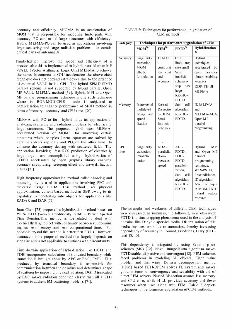
TABLE 2: Techniques for performance up gradation of CEM methods
Category Techniques for performance upgradation of CEM
MOM®
FEM®
FDTD®
Hybridization®
Accuracy Singularity extraction, MOM elliptic formulation
1.H-LU -computation cost and accuracy
CFL limit- step size small Semi implicit schemes- step size large RK-HO-FDTD.
Hybrid techniques accelerated by open graphics library enabling accuracy DDP-FE-BI-MLFMA
Memory Incremental multilevel filling and sparsi- fication
Nested Dissection- DDM. Semi Implicit Schemes. -
Sub cell algorithm, RK-HO-FDTD.
ID-MLFMA and MLFMA-ACA, Open MP parallel programming
CPU time
Singularity extraction, Paralleli- zation
DDA- parallelization- increases speed
ADI- FDTD, LOD-FDTD –paralleli-zation, Sub cell algorithm, RK-HO-FDTD.
Hybrid MPI and Open MP parallel programming technique, WCS-PSTD, Preconditioner, ID algorithm. AWE technique in MOM-FDTD hybrid reduce resource
The strengths and weakness of different CEM techniques were discussed. In summary, the following were observed: FDTD is a time stepping phenomena used in the analysis of domains like Debye dispersive media. Discretization of th is media imposes error due to truncation, thereby increasing dependency of accuracy to Courant, Friedrichs, Lewy (CFL) limit [8, 10]. This dependency is mit igated by using Semi implicit schemes (SIS) [12]. Novel Runge-Kutta algorithm makes FDTD stable, dispersive and convergent [18]. FEM schemes faced problems in modeling 3D objects, Eigen value problem and thin wires. Domain decomposition method (DDM) based FETI-DPEM solves FE system and makes good in terms of convergence and scalability with aid of direct FEM solvers. Nested Dissection assures less memory and CPU t ime, while H-LU prov ides accuracy and fewer resources when used along with FEM. Table 2 depicts techniques for performance upgradation of CEM methods.

52
Iterative solvers face difficulty in convergence due to existence of PML. However DtN approximation, preconditioners promotes convergence [25]. DDM makes it applicable to large domain problems. MLFMA acceleration incorporates accuracy as depicted DDP-FE-BI-MLFMA technique, is suitable for all domains [29]. MOM needs the domain to be well conditioned and error controllable. Ill conditioning effects could be reduced by potentially splitting the domain or by the use of preconditioners. Error could be controlled by using semi implicit schemes and formulation like MOM elliptic approach [36]. Various hybrid combinations and advanced hybridization like FE-BI-MLFMA with limited scalability and computational complications [28,29], ID-MLFMA [67], MLFMA-ACA that treat mult iscale problems [67], Open MP VALU[69], MLFMA, W CS-PSTD[73], DGTD–TDBI with truncated by EAC shows better performance in terms of accuracy, convergence and CPU time [74]. Most widely used softwares are CST®[75] based on Finite Integration Technique, HFSS® [76] based on FEM and FEKO ® [77] based on MOM and FEM.
6. Future of CEM
CEM Research has wide scope of evolution in next few decades. A few techniques have been incorporated to improve the performance of this stream of research. The hybrid GPU–CPU parallelization may acquire considerable attention in few years. The computational time is expected to be reduced by implementing fast convergence methods and implementing efficient preconditioners. Multi scaling methods that are fast and accurate use efficient DDM methods like d iscontinuous Galerkin methods and generalized transition matrix. Methods with higher order modeling capabilit ies with high order basis function, characteristic basis functions are expected to have considerable growth. Novel integral and differential methods can be used for several realistic applicat ions and these applications may also require choice of d ifferent material in cases like nonlinear sensing, Spectroscopy, frequency generation. The collaboration of CEM with other field of research like Mult iphysics aids in dealing with realistic applications and has potential to grow tremendously.
7. Conclusion
A review on different computational electromagnetics shows that these methods are application specific. Selecting a correct method that will afford fast and accurate solutions may be a difficult task. Comparing the performance of FDTD, FEM, MLFMA accelerated MOM will give better insight on CEM. Although FDTD uses SIS for enhancing accuracy, parallelizat ion for reducing CPU t ime and Novel RK-HO FDTD to enhance both, is time consuming. On the other hand FEM is producing spurious solution that makes it not ideal for Eigen value problem. However MOM accelerated MLFMA is found to be suitable for well-conditioned and error controllable solver. Preconditioners
speed the convergence, parallelization makes CPU time usage less, incremental multilevel filling and spars ification reduces memory and MOM elliptic formulation promotes the accuracy, thereby proving efficiency of MOM. To cater the needs of emerg ing technology CEM incorporates the technique called hybridisation. Introduction of this technique helps in achieving the efficiency in terms of computational time, memory storage and accuracy. ID algorithm reduces computational issues, ID-MLFMA and MLFMA-ACA reduces mult iscale problem, open MP-VALU MLFMA method enhances the CPU t ime, in turn making MOM hybrid more reliable. On analysing pros and cons of CEM techniques, it could be noticed that in application specific tasks, hybridisation of techniques involving MOM accelerated MLFMA are exh ibit ing better results in terms of memory, accuracy and computational time.
References
[1] C. Christopoulos, Review of Computational Electromagnetics in Electromagnetic Compat ibility Applications, IET 8
th International Conference, Wroclaw,
pp. 11-14, 2011. [2] Hubing, Todd H, and J. L. Drewniak, Computer
modeling tools for EMC, Proceedings of the 12th
Annual
Review of Progress in Applied Computational
Electromagnetics, pp. 857-860. 1996. [3] B. Ravelo, Y. Liu and A. K. Jastrzebski, PCB Near-Field Transient Emission Time-Domain Model, IEEE
Transactions on Electromagnetic Compatibility 57(6): 1320-1328, Dec. 2015.
[4] Y. Liu and B. Ravelo, Application of Near-Field Emission Processing for Microwave Circuits under Ultra -Short Duration Perturbations, Advanced Electromagnetics
1(3): 24-40, 2012.
[5] Karl F. Warn ick, Numerical Methods for Engineering , Sci Tech Pub, 2011. [6] D.B. Davidson, A Review of Important Recent Developments in Full-wave CEM for RF and Microwave Engineering, 3rd International Conference on
Computational Electromagnetics and Its Applications [ICCEA], Beijing China, pp. 1- 4, 2004. [7] Sankaran Krishnaswamy, Accurate domain truncation techniques for time-domain conformal methods, PhD diss, ETH ZURICH, 2007. [8] J.P. Berenger, A Perfect ly Matched Layer for the Absorption of Electromagnetic Waves, Journal of
Computational Physics 114(2): 185-200, 1994. [9] M. Niziolek, Rev iew of Methods used for Computational Electromagnetics , 2nd International Students Conference on
Electrodynamics and Mechatronics [SCE 11 '09], Silesia, 2009.

53
[10] Zhun Yang, A Modified PML in FDTD Modeling of a Uniaxial Wire medium, IEEE Antennas and Wireless
Propagation letters 13: 1191-1194, 2014. [11] Zheng Yu Huang, Li-Hua Shi, Bin Chen, and Ying-Hui Zhou Li-Hua Shi, Bin Chen, and Ying-Hui Zhou, A New Unconditionally Stable Scheme for FDTD Method Using Associated Hermite Orthogonal Functions , IEEE
Transactions on Antenna and Propagation 62(9): 4804-4809, 2014. [12] Saif A. Al Hasson and Joerg Schoebel, Spheroidal FDTD Method for Modeling 3-D Structures in Open and Closed Domains , IEEE Transactions on Antenna and
Propagation 63(7): 3055-3064, 2015. [13] Alireza Samimiand Jamesina J. Simpson, An Efficient 3-D FDTD Model of Electromagnetic Wave Propagation in Magnetized Plasma, IEEE Transactions on Antenna and Propagation 63(1) : 269-279, 2015. [14] Iraklis Giannakisand Antonios Giannopoulos , Time-Synchronized Convolutional Perfectly Matched Layer for Improved Absorbing Performance in FDTD, IEEE
Transactions on Antenna and Propagation 14: 690-693, 2015. [15] Run Xiong, Bin Chen, and Dagang Fang, An Algorithm for the FDTD Modeling of Flat Electrodes in Grounding Systems , IEEE Transactions on Antenna and
Propagation 62(1): 345-353, 2014. [16] Run Xiong, Cheng Gao, Bin Chen, Yan-Tao Duan, and Qin Yin, Uniform Two-Step Method for the FDTD Analysis of Aperture Coupling, IEEE Antennas and
Propagation. Magazine 56 (6): 182-192, 2014. [17] Yi-Gang Wang, Bin Chen, Hai-Lin Chen, Yun Yi, and Xin-Li Kong, One-Step Leapfrog ADI-FDTD Method in 3-D Cylindrical Grids with a CPML Implementation , IEEE
Transactions on Antenna and Propagation 13: 714-717, 2014. [18] Tadashi Hemmi, Fumie Costen, Salvador Garcia, Ryutaro Himeno, Hideo Yokota, and Mehshan Mustafa, Efficient Parallel LOD-FDTD Method for Debye-Dispersive Media, IEEE Transactions on Antenna and Propagation 62 (3) : 1330-1338, 2014. [19] Zhi-Hong Lai, A Domain Decomposition Fin ite Difference Time Domain (FDTD) Method for Scattering Problem from Very Large Rough Surfaces , IEEE Transactions on Antenna and Propagation 63 (10): 4468 -4476, 2015. [20] Min Zhu, Jean-Fu Kiang, and Raj Mittra, Study and Analysis of a Novel Runge–Kutta High-Order Fin ite-Difference Time-Domain Method, IET Microwave Antennas
Propagation 8(12): 951–958, 2014. [21] www.feko.info [22] Bangda Zhouet al, Direct Finite Element So lver of Linear Complexity for Analyzing Electrically Large
Problems , Applied Computational Electromagnetics (ACES), 2015 31st International Review of Progress, pp.1 – 2, 2015. [23] Ting Wan, Qingwen Zhang, Tao Hong, Zhen hong Fan, Dazhi Ding, Ru Shan Chen, Fast Analysis of Three -Dimensional Electromagnetic Problems Using Dual-Primal Fin ite-Element Tearing and Interconnecting Method Combined W ith H-Matrix Technique, IET Microwave
Antennas Propagation 9(7): 640–647, 2015. [24] Haksu Moon, Fernando L. Teixeira, Joonshik Kim, and Yuri A, Trade-Offs for Unconditional Stability in the Fin ite-Element Time-Domain Method, IEEE Transactions on
Antenna and Propagation 24(6): 361-363, 2014. [25] Ivan Voznyuk, HerveTortel and Amelie Litman, 3-D Electromagnetic Scattering Computation in Free-Space with the FETI-FDP2 Method, IEEE Transactions on Antenna and
Propagation 63(6): 2604-2613, 2015. [26] Ali Aghabarati and Jon P. Webb, Algebraic Mult igrid Combined With Domain Decomposition for the Finite Element Analysis of Large Scattering Problems , IEEE
Transactions on Antenna and Propagation 63(1): pp. 404-408, 2015. [27] Zhi-Qing Lu, Xiang An, Non-Conforming Fin ite Element Tearing and Interconnecting Method With One Lagrange Multiplier for So lving Large-Scale Electromagnetic Problems , IET Microwave Antennas
Propagation, 8(10): 730–735, 2014. [28] Jian Guan, Suyan and Jian-Ming Jin, An Accurate and Efficient Finite Element-Boundary Integral Method with GPU Acceleration for 3-D Electromagnetic Analysis , IEEE
Transactions on Antenna and Propagation , 62(12): pp. 6325-6336, 2014. [29] Ming Lin Yang, Hong-Wei Gao, Wei Song and Xin-Qing Sheng, An Effective Domain-Decomposition-Based Preconditioner for the FE-BI-MLFMA Method for 3D Scattering Problems , IEEE Transactions on Antenna and
Propagation 62(4): 2263-2268, 2014. [30] Huan-Ting Meng, GPU Accelerated Fin ite-Element Computation for Electromagnetic Analysis , IEEE Antennas
and Propagation Magazine 56(2): 39-62, 2014. [31] Yong Zhang and Hai Lin, A New Preconditioning Scheme for MLFMA Based on Null-Field Generation Technique, IEEE Transactions on Antenna and Propagation (14): 289-292, 2015. [32] B.Carpentieri, Preconditioning for Large-Scale Boundary Integral Equations in Electromagnetics , IEEE
Antennas and Propagation Magazine 56(6): 338-345, 2014. [33] M. A. Echeverri Bautista, M. A. Francavilla, F. Vip iana, and G. Vecch i, A Hierarch ical Fast Solver for EFIE-MOM Analysis of Mult iscale Structures at Very Low Frequencies , IEEE Transactions on Antenna and
Propagation 62(3): 1523-1528, 2014.

54
[34] Willem J. Strydom and Matthys M. Botha, Charge Recovery for the RW G-Based Method of Moment, IEEE
Transactions on Antenna and Propagation 14: 305-308, 2015. [35] Fu-Gang Hu, Errors in Pro jection of Plane Waves Using Various Basis Functions , IEEE Antennas and
Propagation Magazine 51(2): 86-98, 2009. [36] Ozgur Ergul and Barıscan Karaosmanoglu, Low-Frequency Fast Multipole Method Based on Multiple-Precision Arithmetic, IEEE Transactions on Antenna and
Propagation 13, 975-978, 2014 [37] F.Vipiana, Mult i-Resolution Approach to Three-Dimensional Method-of-Moments Problems, Computational
Electromagnetics International Workshop [CEM], Izmir, pp.11-14, 2009. [38] Gopinath Gampala, Comparison of Various CEM Methods for Antenna Array Applications , 31st International
Review of Progress in Applied Computational
Electromagnetics (ACES), pp. 1-2, 2015. [39] Xiao Chuan Wang, Multisolver Domain Decomposition Method for Modeling EMC Effects of Multiple Antennas on a Large A ir Platform, IEEE
Transactions on Antenna and Propagation 54(2): 375-388, 2012. [40] Daniel L. Dault, The Generalized Method of Moments for Electromagnetic Boundary Integral Equations , IEEE
Transactions on Antenna and Propagation 62(6): 3174-3188, 2014. [41] Xiao-Min Pan, Improved Algebraic Preconditioning for MOM Solutions of Large-Scale Electromagnetic Problems, IEEE Transactions on Antenna and Propagation 13: 106-109, 2014. [42] F. Andriulli, A multiplicative Calderon preconditioner for the Electric Field Integral Equation, IEEE Transactions
on Antenna and Propagation 56(8): 2398–2412, 2008. [43] Francesca Vipiana, Incremental Mult ilevel Filling and Sparsificat ion for the MOM Solution of Multiscale Structures at Low Frequencies , IEEE Transactions on
Antenna and Propagation 56(6), 1707-1710, 2014. [44] Te-Kao Wu, Accurate PMCHWT Solutions for Scattering from Arb itrarily-Shaped Penetrable Bodies of Revolution, IEEE Antennas and Propagation Magazine 56, (5): 315-320, 2014. [45] D. Chatterjee, A Selective Review of High Frequency Techniques in Computational Electromagnetics , Applied
Electromagnetics Conference [AEMC 2007], Kolkata, India, pp. 1 – 4, 2007. [46] L.J. Jiang, Review of Low Frequency Computational Electromagnetics, IEEE International Conference on
Microwave Technology & Computational Electromagnetics (ICMTCE), Beijing, China, pp. 1-1, 2011.
[47] Hossein Azodi, A Fast 3-D Deterministic Ray Tracing Coverage Simulator Including Creeping Rays Based on Geometry Voxelization Technique, IEEE Transactions on
Antenna and Propagation 63(1): 210-220, 2015. [48] Xiao Meng, An Accelerated Ray Tracing Method Based on the TSM for the RCS Pred iction of 3-D Large-Scale Dielectric Sea Surface, IEEE Transactions on Antenna
and Propagation 14: 233-236, 2015. [49] Yu Mao Wu, The Contour Deformation Method for Calculating the High Frequency Scattered Fields by the Fock Current on the Surface of the 3-D Convex Cylinder, IEEE Transactions on Antenna and Propagation 63: 2180 – 2190, 2014. [50] B. Persson, On Modeling RCS of Aircraft for Flight Simulation, IEEE Antennas and Propagation Magazine, 56, (4), 37 -43, 2014. [51] Alex Gendelman, Mult ilevel Physical Optics Algorithm for Near Field Scattering, IEEE Transactions on
Antenna and Propagation 62(8): 4325-4335, 2014. [52] Qi I. Dai, Mult ilevel Fast Multipole Algorithm for Characteristic Mode Analysis, arXiv preprint arXiv, 1412.1756, 2014. [53] Honarbakhsh, B, and A. Tavakoli, Analysis of Thin
Microstrip Antennas by Meshless Methods, Applied Computational Electromagnetics Society Journal 27(12): 2012.
[54] Razmjoo, H., M. Movahhedi, and A. Hakimi, Modification on a Fast Meshless Method for Electromagnetic Field Computations , IET Science,
Measurement & Technology 5(5): 175-182, 2011. [55] A. Capozzo li, O. Kilic, C. Curcio, and A. Liseno, The success of GPU computing in Applied Electromagnetics , ACES Express Journal 1(4): 113-116, 2016. [56] Ulrich Jakobus, Benefits and Challenges of GPU Accelerated Electromagnetic So lvers from a Commercial Point of View, ACES Express Journal 1(4): 117-120, 2016. [57] E. A. Forgy, A Hybrid MOM/FDTD Technique for
Studying Human Head/Antenna Interactions, IEEE-APS Conference, Waltham, MA, pp. 81 – 84, 1998. [58] Fatih Kaburcuk, IMR Technique for Antenna and Scattering Problems Using Hybrid Solutions Based on the MOM and FDTD Method, International Conference on
Electromagnetics in Advanced Applications (ICEAA), Palm
Beach, pp. 1149 – 1152, 2014. [59] Tomasz Topa, Efficient Wideband Analysis of Electromagnetic Problems Using the Awe Adaptive Technique with the Hybrid MOM-FDTD Method,17
th
International Conference on Microwaves, Radar and
Wireless Communications [MIKON], Wroclaw, pp.1-4, 2008.

55
[60] Tomasz Topa, FDTD/PO Hybrid Method for Analysis of Planar Antennas Radiating near Large Conducting Objects, 21
st International Conference on Radioelektronika
(RADIOELEKTRONIKA), pp. 1 – 3, 2011. [61] R. Alias, A Modified Equivalent Conducting Surface Boundary Using Hybrid FEM -FDTD Technique, 8
th
International Multitopic Conference [INMIC], Lahore, pp. 698 – 702, 2004. [62] R. Alias, Dual Band Patch Antenna Design Using Modified Surface Boundary Hybrid FEM -FDTD Technique, Asia-Pacific Conference on Applied Electromagnetics [APACE 2005], Johor, pp. 21-25, 2005. [63] Salski B, Hybrid FDTD Modeling of a Two-Level Atomic System, 14
th International Conference on
Numerical Simulation of Optoelectronic Devices (NUSOD), Palma de Mallorca, pp. 83 – 84, 2014. [64] T.P. Stefanski, Analysis of Radiation and Scattering Problems with the Use of Hybrid Techniques Based on the Discrete Green's Function Formulation of the FDTD Method, International Conference on Electromagnetics in
Advanced Applications (ICEAA), Turin, pp.375 – 378, 2015. [65] T.P. Stefanski, Hybrid ization of the FDTD Method with Use of the Discrete Green’s Function , 8
th European
Conference on Antennas and Propagation (EUCAP), The Hague, pp. 1149-1152, 2014. [66] Hong Wei Gao, Application of Interpolative Decomposition to FE-BI-MLFMA for Fast Computation of Monostatic Scattering fro m 3-D Complex Composite Objects , IEEE Transactions on Antenna and Propagation , 13: 1490 -1493, 2014. [67] Wei-Bin Kong, Analysis of Multiscale Problems Using the MLFMA with the Ass istance of the FFT-Based Method, IEEE Transactions on Antenna and Propagation 63 (9): 4184-4188, 2015. [68] Yong Zhang and Hai Lin, MLFMA-PO Hybrid Technique for Efficient Analysis of Electrically Large Structures, IEEE Transactions on Antenna and Propagation 13:1670-1676, 2014. [69] Jinbo Liu, Parallelization of the Multilevel Fast Multipole Algorithm by Combined Use of Open MP and VALU Hardware Acceleration, IEEE Transactions on
Antenna and Propagation 62(7): 3884-3889, 2014. [70] Z. He, Parallel March ing-on-in-Degree So lver of Time-Domain Combined Field Integral Equation for Bodies of Revolution Accelerated by MLACA, IEEE Transactions on
Antenna and Propagation 63(8): 3705 -3710, 2015. [71] Tian-Qi Fan, Open-GL Based Hybrid GO/PO Computation for RCS of Electrically Large Complex Objects , IEEE Transactions on Antenna and Propagation , 13: 666-669, 2014. [72] Robert Brem, A Shooting and Bouncing Ray (SBR) Modeling Framework Involving Dielectrics and Perfect
Conductors, IEEE Transactions on Antenna and
Propagation, 63(8): 3599-3609, 2015. [73] Juan Chen, A WCS-PSTD Method for So lving Electromagnetic Problems Both With Fine and Electrically Large Structures, IEEE Transactions on Antenna and
Propagation 62(5): 2695-2701, 2014. [74] Ping Li, A Hybrid Time-Domain Discontinuous Galerkin Boundary Integral Method for Electromagnetic Scattering Analysis, IEEE Transactions on Antenna and
Propagation 62(5): 2841-2846, 2014.
[75] CST, https://www.CST.com [76] HFSS, http://www.ansys.com/Products/Electronics/ANSYS-HFSS
[77] FEKO, https://www.feko.info