a review of the present and future utilisation of frp composites in the civil
TRANSCRIPT
Construction and Building Materials 24 (2010) 2419–2445
Contents lists available at ScienceDirect
Construction and Building Materials
journal homepage: www.elsevier .com/locate /conbui ldmat
Review
A review of the present and future utilisation of FRP composites in the civilinfrastructure with reference to their important in-service properties
L.C. HollawayUniversity of Surrey, Guildford, Surrey, UK
a r t i c l e i n f o a b s t r a c t
Article history:Received 13 December 2009Received in revised form 9 April 2010Accepted 9 April 2010Available online 20 May 2010
Keywords:PolymersFibresCompositesAll-composite structuresHybrid structuresNew structural formsSustainable structuresStructures associated with renewableenergy
0950-0618/$ - see front matter � 2010 Published bydoi:10.1016/j.conbuildmat.2010.04.062
E-mail address: [email protected]
The paper discusses the development of the advanced polymer composite material applications in thebuilding and civil/structural infrastructure over the past three to four decades. It endeavours to identifyand prioritise the important in-service research areas which are necessary to improve the understandingof the behaviour of FRP materials and FRP structural components. The paper demonstrates the types ofstructures which have been developed from the FRP composite material and the most advantageousway to employ composites in civil engineering. The material has extraordinary mechanical and importantin-service properties which when combined with other materials are utilised to improve the stiffness/strength, durability, the whole-life cost benefit and the environmental impact. The paper concludes bysummarising key successes of the advanced polymer composite in the civil infrastructure and suggestsareas in which, if they are employed innovatively, FRP composites could be used with great advantage.
� 2010 Published by Elsevier Ltd.
1. Introduction
For more than 30 years following the Second World War theconstruction industry showed a lack of investment in researchand development and consequently potential material investors,in the technological revolution in materials and in their processingtechniques, were being explored in other sectors of the manufac-turing industry and inevitably the construction industry was by-passed, Latham [134] and Egan [61]. Nevertheless, notwithstand-ing the criticisms by these authors there is evidence in the late1970s and into the 1980s of an interest by the research depart-ments of universities, research institutes and a few civil engineer-ing consultants in advanced polymer composite (APC) materials;these materials consist of high-strength and stiffness fibres pro-tected by a high-performance thermosetting polymer. The early re-search and development and the innovations in structural and civilengineering APC systems was instrumental in the current interest,throughout the world, in the use of APC in the civil engineeringindustry.
The polymer composite derives its mechanical characteristicswholly from those of the fibre and the quality of the fibre/matrix
Elsevier Ltd.
interface, therefore the most important properties required of thepolymer is its physical and in-service characteristics. High-perfor-mance thermosetting resins are required to provide specific prop-erties in highly demanding environments. These matrices mustpossess high dimensional stability at elevated temperatures andthermal resistance, low water absorption, good chemical resis-tance, high mechanical strength, excellent stiffness and high com-pressive strength. This combination of properties is essential foradvanced composites to be utilised in the construction industry,but due to the increase in cross-linking density observed duringpolymerisation, conventional thermosetting matrices are consid-ered to be brittle and this limits the damage tolerance of the com-posite, O’Brien [176], Hollaway [98].
Before discussing the current and future composite structuralsystems used in the civil infrastructure it is important to discussthe characteristics of the material which make them attractive insome areas of construction and other characteristics which requireto be improved before full confidence in the material is achieved.This paper, therefore, will be divided into two parts.
Part A will examine the in-service and physical properties ofpolymers and composites for utilisation in civil engineering. Thesecharacteristics are fundamental for a successful structural systemto be used in the civil infrastructure.
Part B will demonstrate how these unique characteristics ofAPCs can be used to form,

2420 L.C. Hollaway / Construction and Building Materials 24 (2010) 2419–2445
� ‘All-FRP-composite’ structures.� Combined with other engineering materials to improve the
stiffness, strength and durability of the overall composite struc-tural member.� Future generations of FRP structural members associated with
the construction industry.
The mechanical properties of the component parts of the com-posite are clearly important but this area has been well docu-mented, Hollaway and Head [90], Hull and Clyne [107], Kim[125] and only a brief discussion will be included in Part A as (a)mechanical properties will be affected by the in-service propertiesover time and (b) for completeness. Likewise, a brief discussionwill be given of the mechanical properties of the FRP composite;typical mechanical values are given in Appendix A.
In civil engineering the APC is generally referred to as the fibre-reinforced polymer (FRP) composite; this description will be usedthroughout this paper.
2. Part A: the important physical and in-service properties ofthermosetting polymers used in the civil infrastructure
2.1. Introduction
The FRP engineering structural composites must possess notonly sufficient strength and stiffness properties to resist the fullsuperimposed and self-weight loads to which the structure is ex-posed but also the relevant in-service and physical characteristicsrequired to function in the aggressive and sometimes hostile envi-ronments encountered in the construction industry; these lattercharacteristics are clearly just as important as the mechanicalproperties. The greater the degradation of structures over timethe lower will be their load carrying capacity. Consequently, themost important properties of the matrix (the polymer), which pro-tects the load carrying fibre component of the composite, are itsphysical and in-service characteristics.
The vinyl-esters, the epoxies and the polyesters are the thermo-setting matrices which are utilised for composite structural mem-bers in the civil infrastructure; all are crossed linked. A wide rangeof amorphous and crystalline polymer materials (an amorphousand a crystalline polymer are those in which there is a random or-der of their atoms and those in which there is an orderly repeatingpattern of their atoms, respectively) can be used to form fibres. Inthe construction industry the three fibres which are invariablyused are the glass, the aramid and the carbon fibres. The basicmechanical properties of the component parts of the composites,their interaction and the techniques for the manufacture of the fi-bres and the composite materials have been discussed many timesin a number of publications, Kim [125], Hollaway and Head [90],Karbhari [118], Hollaway [98] and will not be dealt with here.However, the physical and in-service characteristics of the compo-nent parts of the FRP composite will be discussed in the subse-quent sections. These characteristics are of primary importancein relation to the durability of the polymer and hence of the FRPcomposite.
2.2. Polymerisation
It is essential that polymers are manufactured correctly forthem to perform their in-service functions efficiently. Polymerisa-tion is a process of bonding together repeating molecular buildingblocks, known as monomers, through a variety of reaction mecha-nisms to form large chainlike or network molecule of relativelyhigh molecular mass known as a polymer. At least one hundredand often thousands of monomer molecules must be combined
to form a product that has certain physical properties such ashigh-modulus of elasticity and high tensile strength values or hasthe ability to form fibres. There are two classes of polymerisation,these are:
� Addition polymerisation is a process in which monomers react toform a polymer without the formation of by-products. Additionpolymerisation is usually undertaken in the presence of a cata-lyst, which in certain cases controls the structural properties ofthe polymer. In this process monomers are dissolved in a sol-vent that is later removed. The monomers quickly combine byan addition reaction without losing any atoms, so that the poly-mer has the same basic formula as the monomer.� Condensation polymerisation is a slower stepwise reaction. It
results in the loss of atoms or groups of atom as by-productsof the linking monomers. Most condensation polymerizationsare of a kind of copolymerization, usually consisting of two ormore types of monomers. The number of monomers in a poly-mer determines the degree of polymerization of the polymer.When the number of monomers is high, the compound is saidto have a high degree of polymerization and is called a highpolymer.
As mentioned earlier thermosetting resins are crossed linkedpolymers, in which their molecular structure is a network. Theseresins are formed under the influence of heat and once formed theydo not melt or soften upon reheating, and do not dissolve in sol-vents; they can be made by either addition or condensation poly-merisation. It is essential that the correct mix ratio is obtainedbetween the epoxy resin and the curing agent to ensure that acomplete reaction does take place as the curing agent molecules‘co-react’ with the thermosetting resin molecules in a fixed ratio.If the mix is not in the correct proportions, un-reacted resin or cur-ing agent will remain within the matrix, and this will affect the fi-nal properties of the polymer after cure.
There are two procedures which are used to polymerise a ther-mosetting polymer for the civil engineering industry, these are:
� The cold cured systems where the polymer is cured (polymer-ised) at ambient temperature on site, generally in the regionof 10–30 �C; the lower the curing temperature the longer isthe cure time. It is advisable with cold cure resins to providea post cure with a higher temperature over an extended periodof time. This regrettably is not generally done on civil engineer-ing site.� The hot cured system where the polymerisation is performed in a
factory environment at elevated temperatures of the order of130 �C; this is generally an automated production procedure.
The cold and hot cured resins have different formulations, con-sequently, a hot cured system cannot be polymerised using a coldcuring agent and vice versa. Attention must be given to the sitetemperature when using the cold cure polymers; the environmen-tal temperature under working conditions should be some 20� Cbelow the glass transition temperature (Tg).
2.3. Temperature
The influence of temperature on polymers can be separated intotwo effects:
� short-term and� long-term.
The short-term effect is generally physical and is reversiblewhen the temperature returns to its original state, whereas the

L.C. Hollaway / Construction and Building Materials 24 (2010) 2419–2445 2421
long-term effect is generally dominated by chemical change and isnot reversible; this effect is referred to as aging. As the temperaturevaries all properties of the polymer will change, consequently, tofully characterise the temperature dependent material, propertiesshould be measured over a range of temperatures. To study oneor more of the properties as a function of temperature, a thermalanalyser is used; it scans property change over a wide temperaturerange. The differential scanning calorimeter (DSC) is used to under-take these measurements. The heat input and temperature rise forthe material under test are compared with those for a standardmaterial both subjected to a controlled temperature programme.The general principles of DSC are outlined in ISO standard, ISO11357-1 [1997] for polymers and it contains a bibliography givingreferences to more detailed information.
Particular cases of the effects of temperature on polymers are:(i) the glass transition temperature and their melting point, (ii)their thermal expansion, (iii) their thermal conductivity, and (iv)the effect of ultraviolet light although this is not strictly a temper-ature property.
2.3.1. Glass Transition Tg and melting point Tm
The temperature below which the physical properties of anamorphous or an amorphous/crystalline polymer vary in a mannersimilar to that of a solid phase (brittle or glassy state) and abovewhich it behaves in a manner similar to that of a liquid (rubberystate) is known as the glass transition temperature (Tg). More spe-cifically, the glass transition state is a pseudo second order phasetransition in which a supercooled melt returns on cooling to aglassy structure. The Tg is usually associated with the wholly amor-phous or the amorphous/crystalline polymer (the epoxies used inconstruction come under the latter class of material) in which itchanges from the solid phase to the rubbery state (or vice versa)gradually over a finite temperature range and the Tg is the mid-point of this range. As polymers below the Tg, are rigid, they haveboth stiffness and strength, but above the Tg, the amorphous (oramorphous/crystalline) polymers are soft elastomers or viscousliquids, and have no stiffness or strength. The Tg of crystalline(thermoplastic) polymers are more complex than those of theamorphous/crystalline (thermosetting) polymers because, in addi-tion to a melting temperature Tm, which takes place over a range ofa few degrees and above which all their crystalline structure disap-pears they also have a second but lower value Tg below which theybecome rigid and brittle. Slightly different numerical values of theTg may be quoted in the literature depending upon the testingtechnique used. There are two methods which may be used, theseare the Dynamic Mechanical Thermal Analysis (DMTA), [ISO/CDstandard 6721-11 (2001)] and the Differential Scanning Calorime-try (DSC) ISO standard, ISO 11357-1 [1997].
All physical properties of thermosetting polymers depend uponintermolecular cross-links for their strength and as stated above asthe temperature nears its (Tg) value the polymer will begins to soft-en. The temperature at which this happens depends upon the de-tailed chemical structure of the polymer. The hot curedpolyesters, vinyl-esters and epoxies all begin to weaken and breakdown at above 200� C, the cold cured polymers will have a lower Tg
value than that of the hot cured polymers. However, the Tg of somelow temperature (ambient cured) moulded composites, can be in-creased in value by further post curing the polymer at a highertemperature but for any specific cold cure thermosetting polymerthere is a maximum value of the Tg, irrespective of the post curetemperature value.
2.3.2. The thermal expansion (CTE)The CTE is the change in length per unit rise in temperature. The
CTEs of polymer materials are of the order of 100 � 10�6, conse-quently, they are an order higher than those of the conventional ci-
vil engineering materials. The CTEs vary with temperature rangesand are calculated as the slope of the secant line of the thermalexpansion curve between the reference temperature (generallythe normal environmental temperature) and the temperature ofinterest. The CTE of thermosetting polymers is influenced mainlyby the degree of the cross-linking of the molecules of the materialand the overall stiffness of the units between the cross-linkages.This property must be considered in structural design when joining apolymer or polymer composite to a dissimilar material.
2.3.3. The Thermal conductivityThe thermal conductivity is a measure of the ease with which
temperature is transmitted through a material. The thermal con-ductivity of all polymers is low; consequently, they are good heatinsulators. To reduce the thermal conductivity of a polymer furtherthe material can be used in the form of a foam. If the value is to beincreased, metallic fillers can be added to the resin at the time ofpolymerization.
2.3.4. Fire resistanceThe polymer component of the composite used in the civil engi-
neering industry is an organic material and is composed of carbon,hydrogen and nitrogen atoms; these materials are flammable tovarying degrees. Consequently, a major concern for the construc-tion engineer using polymers is the problem associated with fire.Most building structures must satisfy the requirements of buildingcodes relating to the behaviour of structures in a fire. A measure offire ratings for buildings refers to the time available in a fire beforethe structure collapses. However, the major health hazard derivedfrom polymer and composites in a fire accident is generated fromthe toxic combustion products produced during burning of materi-als. The degree of toxicity generated depends on the phase of burn-ing of the fire including: oxidative pre-ignition, flamingcombustion or fully developed combustion and ventilation con-trolled fires. Smoke toxicity plays an important role during fireaccidents in buildings, where the majority of people die fromsmoke inhalation.
The basic approaches to reduce the fire hazards of polymers are:
(a) To extinguish the fire, to control the fire, or to provide expo-sure protection for structures on site, by:
� a sprinkler system,� a foam system,(b) To introduce additives into resin formulations, by:
� incorporating halogens into resins formulations (e.g.fluorine, chlorine, bromine and iodine family ofchemicals),
� combining synergists in the resin (e.g. het acid resin),� adding epoxy-layered silicate nano-composites at the
time of formulating the resin. The process is complicatedand at present is expensive for the civil engineeringindustry, Hackman and Hollaway [77].
(c) To apply a passive fire protection system to treat the surfaceof the manufactured composite by using intumescent coat-ing technology. These coatings incorporate an organic mate-rial which will char and evolve gases at a designedtemperature so as to foam the developing char, Correiaet al. [49] and by Keller et al. [122].
These approaches are discussed further in Section 5.1.3concerned with fire in FRP composites.
2.3.5. Ultraviolet light (UV)The ultraviolet light from the radiation of the sun is strong en-
ough to cleave the covalent bonds in organic polymers, causingyellowing and embrittlement. All polymers are susceptible by
2422 L.C. Hollaway / Construction and Building Materials 24 (2010) 2419–2445
varying degrees to the degradation by UV light. For a high degree ofUV resistance, UV stabilisers are incorporated into the polymerduring manufacture. Designers should seek advice from the manu-facturer of the specific materials regarding their UV resistance toascertain whether the UV stability is an important performanceparameter.
2.4. The long-term in-service properties of the thermosetting polymers
2.4.1. IntroductionAs briefly mentioned in Section 1 the polymer serves a number
of functions besides being the binder to hold the fibres together intheir required positions. It provides environmental and damageprotection to the fibres and toughness to the composite. In addi-tion, the polymer has important in-service properties, the density,the bonding and the degree of cross-linking of the molecular struc-ture of the polymer are all function of its short term strength; italso depend upon the type of loading applied to that polymer.The long-term stability of the polymer will be dependent uponits durability in the environment into which it is placed. The stiff-ness of the polymer is a function of its degree of cure which in turnis a function of the degree of cross-linking of the three-dimensionalnetwork of polymer chains; however, the stiffness and strength ofthe polymer are not critical in terms of the composite as the fibresare the stiffening and strength component of the composite. Whatis important is the ability of the material under load to resist theparticular civil engineering environment into which it is placed.
It should be mentioned that all materials will degrade over timeand polymers (and composites) are more resistant to degradationthan many of their competitors.
2.4.2. DurabilityKarbhari et al. [116] noted that although the term ‘durability’
is widely used, its meaning and implications are often ambigu-ous. The authors defined the durability of a material or structureas its ability to resist cracking, oxidation, chemical degradation,delamination, wear, and/or the effects or foreign objects damagefor a specified period of time, under the appropriate load conditions,under specified environmental conditions. The reduction in thematerial properties of the polymer (or composite) by the slowand irreversible variation of the structure of the polymer, mor-phology and/or composition as defined (above) is a chemicalchange in the polymer leading to its aging. The instability ofthe material during in-service use or its interaction with theenvironment into which it is placed is one of the causes of thischange. One of the major concerns of the material is the ingressof moisture and aqueous solutions or the contact with an alka-line environment.
One of the main problems in undertaking detailed analysis ofany durability property is the length of time involved in gatheringthe relevant information. There are many different polymers thatare available to the civil engineer and some of these have beenmodified by chemists over the years to improve a particular phys-ical and in-service property. In addition, additives are on occasionsincorporated into polymers at the time of manufacture to enhanceparticular properties. Each time these polymers are changed/mod-ified the durability will be affected.
The durability of a polymer is a function of the aggressive envi-ronments into which the polymer is placed.
These environments will now be discussed.
2.4.2.1. Polymer permeability/barrier property. Moisture will diffuseinto all organic polymers leading to changes in their mechanical,chemical and thermophysical characteristics. The absorption ofthe moisture will cause mechanisms to be set up such as plastici-zation, saponification or hydrolysis that will cause both reversible
and irreversible changes in the structure of the polymer. A high de-gree of cross-linking of the polymer leads to a decrease in its per-meability with a consequent decrease in the diffusion process, thusit is necessary to fully cure the polymer. A successful method to de-crease the diffusion for civil engineering polymers is to apply anadditive to the matrix polymer at the time of manufacture. Silanes(organofunctional trialkoxysilanes) or organotitanates are twoagents which have been used as a barrier against moisture ingress,van Ooij et al. [220]. Furthermore, epoxy-layered silicate nano-composites introduced into the polymer at the time of manufac-ture has the potential to lower its permeability, thus improvingits barrier properties and its mechanical strengths, Hackman andHollaway [77]. Thus by improving the barrier property, a reductionof the ingress of moisture, aqueous and salt solutions is achieved.However, the utilisation of nano-composites is expensive for theconstruction industry and currently it would be used only undervery special circumstances in construction.
2.4.2.2. Corrosion resistance. The resistance of thermosetting poly-mers to chemical attack depends upon its chemical compositionand the bonding in its monomer. These polymers can degrade byseveral mechanisms, but degradation may be divided into twomain categories, (i) physical and (ii) chemical.
� Physical corrosion is the interaction of a thermosetting polymerwith its environment causing an alteration in its properties butno chemical reaction occurs.� Chemical corrosion is when the bonds in the polymer are bro-
ken by a chemical reaction with the environment in whichthe polymer is situated. During this process the polymer maybecome embrittled, softened, charred, delaminated, discolouredor blistered; these are usually a non-reversible reactions. A cor-rect curing procedure of the polymer is important to reducethese degrading effects.
Thermosetting polymers have a poor resistance to concen-trated sulphuric and nitric acids. Furthermore, the attack of aque-ous solutions occurs through hydrolysis in which moisturedegrades the bonds of the polymer molecules. Polymers with highcrystallinity/density or a high degree of cross-linking will gener-ally have low permeability, thus gasses and other small particleswill not readily permeate through it. Haque et al. [78], Liu et al.[143], Hackman and Hollaway [77] have shown that the ingressof moisture will permeate through polymers over time particu-larly if the polymer (and therefore the composite) is permanentlyimmersed in water or salt solution or is exposed to de-icing saltsolutions.
There are two-ways of measuring durability of polymers:
� Long-term testing in the natural environment.� Accelerated test procedures.
These two methods of testing for durability are described inHollaway [98], which discusses the durability of FRP composites.
3. Mechanical properties of the thermosetting polymer
As mentioned in Section 1 the mechanical properties of thecomponent parts of the FRP composite will not be discussed in full.The main headings of the mechanical properties of polymers whichmust be taken into account when designing FRP composites forconstruction are:
� Ultimate tensile strength. Information may be obtained fromHollaway and Head [90]. Some typical tensile properties aregiven in Appendix A.

L.C. Hollaway / Construction and Building Materials 24 (2010) 2419–2445 2423
� Ultimate compressive strength. The compressive strength of ther-mosetting polymers is usually 1.5–4.0 times higher than in ten-sion. Such a difference can be caused by the presence of variousdefects in the material, including micro cracks, whose influenceis more pronounced in tension. In compression such cracks canbe closed, which creates preconditions for achieving the yieldpoint of the material.� Creep characteristics of polymers. Information may be obtained
from references Hollaway [98], BS 4618-5.3: 1972, Hollaway[93].(a) The time temperature superposition principle (TTSP) [7](b) The time, applied stress superposition principle (TSSP), [37],(c) Further descriptions of the TTSP and TSSP may be found in
Hollaway [93].(d) Cheng and Yang [38] have developed the (TTSP) further by
introducing a matched theoretical calculated curve from asupposed model of transition kinetics in which only timeis involved as the independent variable.
� The uniaxial compressive strength of fibre-reinforced polymerFRP composites is a very complex issue which is still not fullyunderstood. Although FRP composites characteristically possessexcellent ultimate and fatigue strength when loaded in tensionin the fibre direction, compressive properties are not good.Unlike tensile properties which are fibre dominated, compres-sive properties are dependent upon other factors such as matrixmodulus and strength, fibre/matrix interfacial bond strength,and fibre misalignment. Discussions on this topic are given inHull and Clyne [107], ASTM D6641/D6641 M-09 [12].� Stiffness of polymers. Discussions on this topic are given in Hol-
liday and White [100].
Subramaniyan et al. [203], have shown that by the addition ofnanoclays to the polymer the compressive strengths of GFRP com-posites increase.
4. The important physical and in-service of fibres
4.1. Introduction
Fibres can be formed from a wide range of amorphous and crys-talline materials but in the construction industry the three fibreswhich are generally used in structural systems are the glass fibre(the E-glass fibre, the S-glass fibre and the Z-glass fibre), the ara-mid fibre (the aromatic polyamides, Kevlar 49 fibre) and the carbonfibre (the ultra high-modulus fibre, the high-modulus fibre and thehigh-strength fibre). The fibres may be used separately or as a hy-brid of two or three different fibres. The various types and mechan-ical properties of glass fibre, the three types of carbon fibre, and thearamid fibre are discussed in Hollaway and Head [90] andHollaway [97]. The basic manufacturing techniques for the ultra-high-modulus, the high-modulus and the high-strength carbon fi-bres are the same but the heat treatment temperature will begreater the higher the modulus of the fibres, thus, at the highestheat treatment temperature, about 2400� C. (for civil engineeringfibres). The precursor polyacrylonitrile fibres are used for the pro-duction of high-modulus fibres (construction industry) or the pro-duction of high-modulus or ultra-high-modulus (aerospaceindustry). Pitch fibres which are derived from petroleum, asphalt,coal tar and PVC, the carbon yield is high but the uniformity ofthe fibre cross-sections is not constant from batch to batch; thesefibres are used for the ultra-high-modulus carbon fibres (construc-tion industry), Philips [178], Hollaway [87,98]. The definitions of fi-bres used here are the European ones, the US and many countriesin the Far East use the normal and high-modulus terms whendiscussing high-modulus and ultra-high-modulus carbon fibres,respectively.
A typical sequence of operation used to form carbon fibres frompolyacrylonitrile (PAN) precursor include various processes, theseare:
� Stabilisation process in an air oven (oxygen is absorbed) toachieve dimensional stability. Temperature 200–300� C.� Carbonation process is performed in and inert atmosphere (Car-
bon crystallites formed). Temperature > 800� C.� Graphitisation process. (Fibres highly orientated.) Temperature >
1200� C.� Surface treatment.� Fibre winding process.
The three carbon fibres have very different strength and stiff-ness values, the ultra-high-modulus carbon fibre has a typical stiff-ness value up to 400 GPa (for civil engineering, this value can beincreased under higher heat treatment) but a relatively low tensilestrength value of 1800 MPa and therefore will have a low strain tofailure value whereas the high-modulus carbon fibre has a typicalstiffness value of 240 GPa and strength value of 4000 MPa andtherefore a relatively high strain to failure value. The high-strengthcarbon fibre has typical tensile strength values of 4400 MPa andmodulus values of 200 GPa.
The in-service properties of the three main civil engineering fi-bres are similar and will be discussed in the following section.
4.2. In-service properties of civil engineering fibres
4.2.1. CreepThe creep characteristics of glass, aramid and carbon fibres are
very small and are not generally considered in the design of poly-mer composite components for civil engineering.
4.2.2. DurabilityAll glass fibres are very susceptible to alkaline environments,
which is primarily due to the presence of silica in the glass fibres.These conclusions have been made when glass fibres (and there-fore GFRP composites) are immersed into concentrated alkalinesolutions. Mufti et al. [172], however, have shown from field sur-veys that the attack is minimal under civil engineering environ-ments. There are, nevertheless, glass fibres on the market thatare more resistant to this environment and are used to increasethe durability of composites. Advantex, and ARcoteXTM are glassfibres which increase the durability of GFRP composites; the for-mer is manufactured by Ownes Corning, and the latter by Saint-Gobain Vetrotex. Carbon fibres do not absorb liquids and are sub-sequently resistant to all forms of alkali or solvents ingress, Ceroniet al. [36]. Aramid fibres have been reported to suffer some reduc-tion in tensile strength when exposed to an alkaline environment,Uomoto and Nishimura [216].
4.2.3. Effects of hydrolysisMost glass fibres have limited solubility in water but they are
very dependent upon the pH value of the liquid. Jones and Chan-dler [112] have stated that glass fibres are susceptible to chemicalcorrosion when exposed to strong acidic environments (pH valueconsiderably lower than 7) and it is well known that they are alsosusceptible to high alkaline environments (pH values considerablyhigher than 7) in which they are severely degraded due to a com-bination of mechanisms ranging from pitting, hydroxylation,hydrolysis, and leaching. Chloride ions will also attack and dissolvethe surface of the E-glass fibre. Moisture is readily adsorbed andcan exacerbate microscopic cracks and surface defects in the fibreand thus reduce the tensile strength of the glass fibre. The glass fi-bres have high ratios of surface area to weight but the increasedsurface makes them much more susceptible to chemical attack.
2424 L.C. Hollaway / Construction and Building Materials 24 (2010) 2419–2445
4.3. The mechanical properties of the fibres
The tensile strength and stiffness of the reinforcing fibre are two ofthe most important mechanical characteristics. These propertieshave been discussed in Hollaway [98].
5. The civil engineering composite materials
5.1. Introduction
The short term in-service and physical properties of the poly-mer/fibre composite are governed by:
� The basic physical and in-service properties of the polymer andthe fibre; the former is the most important component. Thesehave been briefly discussed in and Sections 2 and 4.� The surface interaction of fibre and resin (the ‘interface’).� The relative proportions of the polymer and fibre, (fibre volume
fraction – the fibres must be well wetted by the resin for thislatter material to be fully effective, this becomes increasinglymore difficult the higher this ratio).� The method of manufacture of the composite.
The long-term durability of the composite will depend upon:
� The type of loading which the composite has to resist and theenvironment into which it is placed; there are two areas to besatisfied:1. The in-service properties – these are largely dependent upon
the matrix material. (These properties of the matrix materialhave been discussed in Section 2.4.)
2. The mechanical property of the composite, which are depen-dent upon the fibre and the interface between the two com-ponent parts.
5.1.1. The surface interaction of fibre and resinThe mechanical performance of a composite material is highly
dependent upon the quality of the fibre–matrix interface. This re-gion is an anisotropic transition region which is required to pro-vide chemical and physical bonding between the fibre and thepolymer. The primary aim of a fibre reinforced matrix compositematerial is to provide an average behaviour of the compositefrom the properties of the components which must act compos-itely for the material to be efficient. It is well known that theapplication of a coupling agent to, say, a glass fibre surface willimprove fibre–matrix adhesion in that composite but in addition,and to a greater degree, it is the mixing of the processing addi-tives; this contribution to composite properties is not well under-stood. The interfacial region of the composite will therefore beaffected not only by the composition of the coating, but also byits distribution on the glass fibre surface and in the compositematrix.
5.1.2. The method of manufacture of the compositeThere are three basic methods for the manufacture of
composites:
� Manual methods – wet lay-up process:(i) The REPLARK method
(ii) The Dupont method(iii) The Tonen Forca method.� Semi-automatic methods
(i) The hot-melt factory-made pre-impregnated fibre (pre-preg).
� Automatic methods
(i) The pultrusion technique(ii) The filament winding method.
(iii) The Resin Transfer Moulding process.
These techniques have been discussed in Hollaway and Head[90]. The automated fabrication methods have a high degree ofproduction control, composite compaction and curing comparedto the manual fabricated techniques and therefore the former tech-nique will have higher values of the in-service properties (andstrength and stiffness values) compared to those of the lattermethods and therefore a more robust resistance to hostileenvironments.
Quality control and quality assurance are important aspects ofcomposites during manufacture as both are dependent upon theperformance characteristics and the overall integrity and durabil-ity of the composite formed. These aspects are particularly impor-tant for civil structures as they are required to withstand harsh andvarying environmental exposure for long periods of time, (e.g.many bridges are designed for some 100 years). Clarke [42] hasdiscussed the importance for a regular inspection regime on allstructures, new or upgraded; these inspections are normallyundertaken for bridges but few buildings are regularly checked.The inspections on the latter are carried out only when there is achange of ownership. Clarke recommends that all building ownersinstigate a regular inspection regime.
A further consideration is that many civil structures are fabri-cated on site with the likelihood of the technique of bonding beingused; the bonding area is likely to be the weakest link, Mirmiranet al. [163]. Achieving a reliable standard of product requires goodquality assurance procedures; this will be easier under factory con-trolled conditions compared with the more difficult site controlledconditions. Clarke [42] has discussed quality control andassurance.
5.1.3. In-service properties of FRP5.1.3.1. Fire resistance. The property of the polymer in a fire hasbeen dealt with in Sections 2–4. It is the polymer which protectsthe fibre and hence is the main component of the degradation ofthe composite in a fire; the following discussion will involve manyproblems met in Section 2.3.4.
Problems associated with the fire resistance of FRP compositesare seen by many civil engineers as the single most critical techni-cal barrier to the widespread use of structural engineering applica-tions in the civil infrastructure. Until recently, only a few researchgroups worldwide had worked on this problem as, due to its com-plexity, it is not as amenable to the simpler types of modelling ap-proach, Mouritz and Gibson [157]. Furthermore, the experimentaltesting regime for fire properties has not progressed as rapidly asthat for the testing of mechanical properties of composites.
When FRP composite materials are exposed to high tempera-tures (300–500� C) the polymer matrix will decompose and will re-lease heat and toxic volatiles. When heated to lower temperaturesin the region of 100–200� C), FRP composites will soften, creep anddistort, and this degradation of the mechanical properties oftenleads to buckling failure mechanisms of load-bearing compositestructures [168]. This degradation will seriously compromise thestructural properties of the FRP material which may lead to failuresthat could jeopardise the building, the building occupants as wellas the fire fighting crews. Nevertheless, numerous research studieshave shown FRP materials to be suitable for a variety of civil engi-neering applications but there is a limited amount of informationregarding their behaviour in fire, Harries et al. [81] and Karbhariet al. [116], consequently, there is a barrier to its use in manybuilding applications. For instance, Keller et al. [122] has statedthat in Switzerland residential buildings with more than threefloors a 90 min fire endurance is required, consequently, the use

L.C. Hollaway / Construction and Building Materials 24 (2010) 2419–2445 2425
of FRP in buildings and parking garages has so far been limited.Externally-bonded FRP strengthened concrete structures are cur-rently required to meet the minimum strength requirements ofthe un-strengthened concrete structure in fire thus any strengthcontribution from the FRP is ignored in a fire situation, [3]; thisrequirement is generally followed in European countries. Chowd-bury et al. [41], Chowdbury et al. [39], Chowdbury [40], Bisbyet al. [28] have shown that with appropriate insulation to the exte-rior of the FRP strengthening system, concrete structures strength-ened with FRP materials can achieve an endurance ratings ofgreater than 4 h. However, after exposure to a severe fire, well-insulated RC members are able to retain most, if not all, of their ori-ginal un-strengthened flexural capacity, particularly if the temper-ature of the compression concrete and reinforcing steel aremaintained below 200� C and 593� C, respectively, Chowdburyet al. [41].
5.1.3.2. Alkaline and ingress of liquid into FRP composites. Matthewsand Rawlings [149] found that the mechanical properties of FRPcomposite materials exposed to moisture penetration dependedupon the sensitivity of the composite to matrix properties, mea-sured as the fibre to polymer tensile strength ratio. Carbon-fibre-reinforced polymer (CFRP) composites have a high-strength ratio,which makes them usually unaffected by moisture absorption. Incontrast, glass fibre-reinforced polymer (GFRP) composites have alow-strength ratio, making them susceptible to moisture attack.Ceroni et al. [36] present a state-of-the-art of the durability ofFRP rebars which highlights issues relating to the material proper-ties and interaction mechanisms that influence the service life ofRC elements.
5.1.3.3. Permeability. Within a FRP composite, the polymer matrixoffers the fibre some protection from moisture attack. However,it is relatively inefficient especially at normal fibre volume frac-tions of 60–65% where the average distance between the fibres isof the order of 2 lm or less. Methods to improve the permeabilityof FRP composites are:
� To apply a thin (few mm) polymer coating (gel-coat) to theouter surface of GFRP structures as a moisture barrier. However,this layer does not offer sufficient protection against moistureintrusion.� The successful use of GFRP composites in wet environments has
been largely due to the development of coupling agents that areapplied directly onto the fibre at the time of manufacture. Aswith the protection of polymers against moisture ingress (Sec-tion 2.4.2.1), silanes (organofunctional trialkoxysilanes) or orga-notitanates are two agents which have been used.
5.1.3.4. Durability of FRP composites. As stated in Section 2.4.2 thedurability of a FRP structural composite depends intrinsically uponthe components of the composite, but in particular on the polymerand is a function of the environments into which it is placed.Therefore the composite durability is related to various factors,such as the properties of the resin, fibre and interfacial character-istics, fabrication process and the environment. The durability ofFRP composites has been defined in (Karbhari et al. [116] for ther-mosetting polymers in Section 2.4.2.
Thus, the results of accelerated and other tests carried out in thelaboratory must represent those in the field and an appropriate testprogramme taking into account the actual usage should be devel-oped, on a case-by-case basis. [114,224,217] undertook tests on fi-bres and FRP rods to study the alkaline resistance, UV resistance,freeze thaw resistance, high temperature resistance, fire resistanceand static fatigue fracture. The results showed:
� Carbon fibres and FRP rods had good durability characteristics.� Aramid fibres and FRP rods had good durability properties
except under static fatigue, UV radiation and acidicenvironment.� Glass fibres had poor durability characteristics as far as their
alkaline resistance is concerned, although they had satisfactorycharacteristics in an acidic and freeze thaw environment. FRPmaterials in general showed poor performance at high temper-atures and therefore their use should be avoided when fireresistance is required.� There is a need to limit the tensile load depending on the dura-
tion of the load in cases where the FRP are used as internalreinforcement.
There are two methods which are be used to obtain informationon the durability of a material. These are field and acceleratedtests, details of these have been given in Hollaway [92,98].
5.1.4. The type of loading which the civil infrastructure composite hasto resist
� Tensile properties.� Compressive properties.� Impact resistance.� Fatigue loading.� Blast loading.� Creep loading
The above mechanical properties have been discussed in Holl-away [98]. An overview of the blast loading and blast effects onstructures is given Ngo et al. [174]. The impact of initially stressedcomposite laminates has been discussed by Sun and Chen [204],Kim [126]. Longinow et al. [142] has discussed research neededto resist terrorists attack.
6. Part B: the utilisation of FRP composites in the civilinfrastructure
Part B will illustrate the types of structural systems that havebeen developed as a result of the unique physical and in-serviceproperties of FRP composite materials; their present and futuredevelopment have been and will be influenced by these properties.Fig. 1 illustrates the development of the fibre matrix compositefrom the early 1970s into the 21st century.
The building industry was the forerunner for the use of compos-ites in the construction industry, with the introduction of Radomesduring the Second World War. The material used for these struc-tures was GFRP (known then as GRP) as it minimally attenuatesthe radio waves passing through them; therefore, it had the phys-ical property of being transparent to radar or radio waves. Duringthe 1950s and into the 1960s the FRP material in building and inconstruction had a very chequered existence with inexperiencedfabricators, generally consisting of one or two operatives, manufac-turing the composite without understanding the fundamentals offabrication or the importance of the correct procedure for curingthe material. By the 1970s consulting architects and civil engineerscommenced to consider FRP composites as a building material andto design composite building structures. The larger fabricatingfirms, which already had experience of manufacturing FRP com-posite units for other industries, entered the building industry withthe fabrication of semi-load bearing and infill panels for housesand larger constructions. The main large building examples ofthese systems in the UK are the class-room structure at Fulwood,Lancashire, the Mondial House, London and the Amex House inBrighton. The fabrication of the panels for these buildings was by

All APC Structures
Manual Construction Building Block System (commenced 1974)
Load bearing and infill panels (commenced 1970s)
Automated Construction(Building Block Systems - Commenced mid 1980s)
Advanced Polymer Composites (APC)(Generally referred to as fibre reinforced polymer[ FRP] in civil engineering)
Rehabilitation(Commenced early 1990s)
Non-matallic Rebars(Commenced mid-1990s)
Construction using APC/conventionalmaterials as composite structural units (Commenced 2000)
Hybrid structures(Commenced 2003)
Repair Retrofitting(Seismic)
RetrofittingStrengthening (Non-seismic)
Combination of APC and conventional materials(This is the most advantageous methods of using APC)
Fig. 1. The development of the fibre matrix composite from the early 1970 into the 21st century.
2426 L.C. Hollaway / Construction and Building Materials 24 (2010) 2419–2445
the hand lay-up method (which has since been updated and isknown as the wet lay-up method), the first building used a glassfibre chopped strand mat and the latter two used a combinationof glass fibre/polyester chopped strand mat and a 0/90 fibre arraymat; the polymer used in all cases was the polyester. There aremany other examples where GFRP composites were used forsemi-load bearing infill panels and where GFRP panel ‘buckets’were used in conjunction with a steel double layer skeletal struc-ture to construct roof systems such as the Covent Garden Marketat Nine Elms, London. The shapes of the above structures were lar-gely of a folded plate construction in order to add stiffness to theoverall structure as the stiffness of GFRP composites were/are low.
The class-room building, in Lancashire was/is ‘all composite’FRP building in the form of a geometrically modified icoshedronand was manufactured from 35 independent self-supported tetra-hedral panels of chopped strand glass fibre reinforced polyestercomposite; the geometrical shape was of folded plate constructionlikewise to provide stiffness to the structure. Twenty-eight panelshave a solid single skin GFRP composite skin and in five of thesepanels circular apertures were constructed to contain ventilationfans. In the remaining seven panels non-opening triangular win-dows were inserted. The wet lay-up manufacturing method wasutilised to manufacture the E-glass fibre/polyester compositeskins. The inside of the panels have a 50 mm thick integral skinphenolic foam core acting as a non-load bearing fire protection lin-ing to the GFRP composite skins; the foam core also maintains aconstant temperature in the class-room, (see Section 2.3.3 for thethermal properties of foam polymers). The geometric icoshedronstructure is separated from the concrete base by a timber hard-wood ring. The FRP panels were fabricated onto a mould lining ofperspex with an appropriate profile to give a fluted finish to the flatsurfaces of the panels. The edges of the panels were speciallyshaped to provide a flanged joint which formed the connectionwith adjacent panels. Sandwiched between two adjacent flangesis a shaped hardwood batten, this provides the correct geometric
angle between the panels; the whole is bolted together using gal-vanised steel bolts placed at 450 mm intervals. The external jointsurfaces between the adjacent panels were sealed with polysul-phide mastic. The glass windows were fixed in position on siteby means of neoprene gaskets. The architect to Lancashire CountyCouncil conceived the idea of the GFRP class-room and developed acomplete school manufactured from GFRP; this latter idea neverdeveloped further than the ‘drawing board’. The single class-roomwas build and continues to be used by the pupils at the Fulwood,Lancashire school.
In 1974, Mondial House situated on the banks of the Thames be-tween Cannon Street station and London Bridge was one of themost prestigious and ambitious building projects both in termsof size and complexity; it was designed as a skeletal RC beamand column structure and clad above the upper ground floor level.The semi-loading cladding panels were contact moulded usingScott Bader Crystic 356PA ‘Class O’ fire resistant polyester laminat-ing resin and isophthalic polyester gel-coat 65PA for weather resis-tance and durability; glass fibre was used as the reinforcingcomponent. In 2007 as telephone exchanges no longer require vastamounts of space and, in addition, to allow for redevelopment ofthat area it was vacated by the Post Office and was demolished.It was, when erected in 1974, the largest exchange in Europe; itwas built as a bomb proof structure at the height of the cold war.The outer skin of the GFRP panel included a gel-coat which usedisophthalic resin, pigmented white, with an ultraviolet stabilizerbacked up with a glass fibre-reinforced polymer laminate; the lat-ter used a 3oz per square foot chopped strand mat and a self-extin-guishing laminating resin reinforced with 9oz per square foot glassfibre chopped strand mat reinforcement. Some degree of rigiditywas obtained from a core material of rigid polyurethane foambonded to the outer skin and covered on the back with a furtherglass reinforced laminate; this construction also provided thermalinsulation. Further strength and rigidity was obtained by the use oflight-weight top hat section beams, manufactured as thin formers

L.C. Hollaway / Construction and Building Materials 24 (2010) 2419–2445 2427
and incorporated and over-laminated into the moulding as manu-facture proceeded. The effect of the beams was transferred to thefront of the panel by means of glass fibre reinforced ties or bridgesformed between the polyurethane foam at the base of each beam.The face of the beam was reeded on the vertical surfaces in order tomask any minor undulations and to provide channels off which thewater ran and thereby cleaned the surface. The reeding also gavethe effect of a matt panel without reducing the high surface whitefinish. The structure was visually inspected in 1994 by a memberfrom Scott Bader and one from University of Surrey and the degra-dation was found to be minimal.
The American Express Building in Brighton was completed in1977 and was build as a composite construction with a skeletalload bearing structure with RC columns, major RC beams and pan-els manufactured from GFRP composites. These latter were used asbeams spanning between 7.2 m and 12.5 m. The GFRP beams sup-ported 2 m high laminated glazing system and the roof structure.This application is more significant from a structural engineeringpoint of view as it involves a semi-structural application of GFRPcomposites. A description of the structure is given by Berry [26]and Roach [188].
Architectural embellishment rather than structural perfor-mance and durability motivated the early applications of GFRPcomposite materials. By the mid-1980s there was a desire by engi-neers to use FRP composites as a structural material and this wasdriven by the need for durable, high-strength and high stiffnessmaterials that could replace the more conventional civil engineer-ing materials in aggressive and hostile environments that aresometimes encountered in civil engineering applications. Thusconsulting civil/structural engineers investigated the possibilityof using automated manufacturing methods for the manufactureof structural components for ‘all composite’ structures; the mainone chosen was the pultrusion technique. At this time structuralunit building blocks were being considered and Maunsell Struc-tural Plastics, (Faber Maunsell now AECOM), Beckenham, Kent de-signed and developed ACCS Plank known as the Manusell Plank.The ACCS construction consisted/consists of a number of interlock-ing fibre-reinforced polymer composite Maunsell Plank unitswhich can be assembled into a large range of different high-perfor-mance structures for use in the construction industry; the panelswere connected to each other and to the connectors by bondingand GFRP toggles were used to maintained the parts togetherwhilst the adhesive polymerised. The details of the Maunsell Plankare shown in Hollaway and Head [90]. The system was initiallymanufactured by the pultrusion technique using isophthalic poly-ester resin and uni-directional, bi-directional and chopped strandmat glass fibre reinforced for the main structural members. Theproduction and material content of the ACCS plank are optimizedto provide highly durable and versatile composites and, in addi-tion, structures can be formed quickly from a small number ofstandard components. The ACCS system is now marketed byStrongwell Corporation, USA as Composolite.
Kendall [123] has given a review of the type of FRP buildingstructures for the future.
From the mid to late 1980s the use of FRP composite materialscommenced to expand and the following section will discuss someof these systems; Canning et al. [32] has discussed the use of ad-vanced composites in the civil infrastructure.
6.1. The All FRP composite bridge structures
The first pedestrian FRP bridge was built in Tel Aviv, Israel in1975, [83]. Since then, others have been constructed in Asia, Europe,and North America. Many innovative pedestrian bridges have beenconstructed using pultruded composite structural shapes and dueto the light-weight materials and the ease in fabrication and instal-
lation many of these bridges have been able to be constructed ininaccessible and environmentally restrictive areas without havingto employ heavy equipment. Some bridges were flown to the sitesin one piece by helicopters; others were disassembled and trans-ported by vehicles and assembled on site. The advancement in thisapplication has resulted in the production of second generation pul-truded shapes of hybrid glass and carbon FRP composites that willincrease the stiffness modulus with very little additional cost. Therecognition of providing high quality fibres at the most effective re-gions in a structural member’s cross-section is a key innovation tothe effective use of these high-performance materials.
The first cable stay, GFRP deck and pylons footbridge was con-ceived and developed in the UK and was erected at Aberfeldy, Scot-land in 1992; this bridge crosses the river Tay in Scotland and joinstwo parts of the Aberfeldy golf course. The deck and pylons wereconstructed from interlocking ACCS Planks; the use of compositematerials resulted in a light-weight structure, which could beerected without the aid of heavy machinery. The durability perfor-mance of this bridge over 16 years of service has been very satis-factory, Stratford [202].
The Bonds Mill Road Bridge, Gloucestershire, England, UK crossesthe Stroudwater Navigation canal near Stonehouse, Gloucestershire,England. It is an electrically operated single bascule lift bridge andwas completed in 1994; it is constructed from 10 ACCS units whichform an integral 3D multi-cellular box structure 8.5 m span and4.25 m wide and 0.8 m depth weighing 4.5 tonnes. The individualACCS units are bonded together through square connectors contain-ing recesses through which mechanical toggles are fastened to en-sure the units do not slip during the bonding operation; they alsoact as mechanical fasteners. The bridge is able to support vehiclesup to 44 tonnes weight. The box structure relies on cold cure adhe-sive bonding with an epoxy adhesives, Head [84].
The Wilcott Bridge, Shropshire, England was constructed in2003 and is a 51.3 m single span suspension footbridge with aslightly cambered slender deck providing a footway 2 m wide. Itwas built in three units and spliced to fabricate the total length.The cross-section of the deck of the bridge consists of six GFRP‘Maunsel Plank’ units; three units were placed in the top surfaceof the deck and three in the bottom. A description of the bridgeis given in Faber Maunsell [67].
These three structures were innovative prestigious structures intheir day and the two footbridge structures are ascetically pleasingbut they were expensive to manufacture and fabricate.
Recently the UK Highways Agency has completed a new bridgeover the M6 motorway consisting of steel primary beams and apultruded FRP deck.
Strongwell, Bristol VA and Chatfield MN, USA, now hold themanufacturing licence for the plank and produce similar panel un-der the trade name of COMPOSOLITE�. Further information can beobtained on this Maunsell Plank system from Hollaway and Head[90] and Strongwell, Bristol, Virginia, USA. There have been somefootbridges recently built that have used COMPOSOLITE�. For in-stance, the New Chamberlain Bridge, Bridgetown, Barbados, wascompleted in 2006. It spans the Careenage River, was designedby AECOM and was constructed from COMPOSOLITE�. This bridgereplaced the steel horizontal swing bridge built in 1872. The com-posite bridge is composed of two 2.13 m (7 ft.) raised side walkswith handrails and a 4 m (13 ft.) wide road in the centre which isfor emergency vehicular traffic only; the lift bridge is of similarconstruction to that of the Bonds Mill bridge.
A bascule FRP composite footbridge of span 56 m was openedin May 2003. This double-cantilever bridge crosses the river Vest-erelven in Fredrikstad, Norway; it is the largest moveable bridgein Scandinavia. One large hydraulic cylinder operates each of the28 m long cantilevers to open and close. The cantilevers are builtas a closed box girder with double curved outer surfaces and

2428 L.C. Hollaway / Construction and Building Materials 24 (2010) 2419–2445
longitudinal and transverse stiffeners. The approximate weight ofa fully equipped unit is 20 tonne of which 9 tonne is the weight ofthe FRP composite materials. The bridge deck is of sandwich con-struction with CFRP laminates and a Balsa wood core; there areembedded heating cables for defrosting during winter. The deckis sufficiently strong to carry a car with up to 2.0 tonne axel load.The bottom flange of the girder is manufactured from single skinCFRP laminates (10–38 mm thick). The internal stiffeners are allsandwich constructions with CFRP and/or GFRP laminates andPVC core materials. All FRP composite material was manufacturedby vacuum assisted resin infusion. A steel construction inside thethickest end of the girder is used to distribute the concentratedbearing loads. The client was Værste AS and Fredrikstad com-mune, the designer was Griff kommunikasjon AS and the con-struction was undertaken by Marine Composites AS, Arendal,Norway.
A footbridge installed by Network Rail was erected over themain Penzance-Paddington railway line at St. Austell, Cornwallduring the weekend of 21–22nd October 2007. It has a central spanof 14 m and three sections each 6 m wide; the composite sectionswere manufactured by Pipex (Plymouth) and the consultant forthis bridge was Parsons Brinkerhoff.
The 47 m span Halgavor suspension bridge which spans the A30road near Bodmin, Cornwall is one of the longest curved compositestructures in Europe; it was opened in July 2001. The bridge deckwas designed to carry pedestrians, cyclists and horses is con-structed of composite materials with bonded structural joints.The 4 m wide deck is supported from four cranked steel masts atthe abutments using suspension cables along the length. The FRPdeck was manufactured by Vosper Thornycroft using resin infusionwith vinyl-ester resin and an ultraviolet (UV) resistant gel-coat.Polyester pultrusions were also used longitudinally to locate thedeck. The composite solution provided easy installation and gaveto the architects’ freedom to design the required shapes, coloursand lines.
The first Russian composite bridge made by vacuum infusionresulted in the development of a product line of arched bridgesfor rivers with span lengths between 15 m and 30 m and a life cy-cle span of 100 years. The use of the vacuum infusion technologyprovided reduced manufacture steps, avoided site assemblingand thus decreased the cost of the structure. The first bridge wasinstalled at the p. Vernadskogo subway station, Moscow in 2008,the structure was designed by light-weight structures BV, theNetherlands and installed by Applied Advanced Technology (ApA-TeCh), Company Ltd., Ushakov et al. [215]; the paper won the bestinnovative construction paper award from the American Society ofCivil Engineers.
A bridge built of composite materials can be constructed andput into service in a relatively short time and at a competitive cost.Its light-weight materials and ease of construction provide large la-bour and traffic control cost savings to offset a higher first cost.Mosallam [167] wrote a state-of-the-Art review of composites forhighway bridge applications.
Keller [121] has presented a review of all-composite bridge andbuilding construction from 1997 to 2000.
7. The combination of FRP composites with other materials toform hybrid systems
7.1. Introduction
The unique properties of advanced polymer composites in thecivil infrastructure suggest their suitability for integration in hy-brid structural systems as well as the development of hybrid FRPmaterials themselves. Hybrid structures are those in which two
(or more) dissimilar materials could structurally compliment eachother. Hybrid systems range from open or closed stay-in-placeformwork to hybrid structural systems, incorporating FRP and con-ventional construction materials. The combination can take manystructural forms, these are:
� All FRP composite bridge decks and the bridge superstructure.� An access to an existing structure for maintenance purposes and
for aerodynamics of the structure – a bridge enclosure and aero-dynamic fairings using FRP units.� The rehabilitation of RC beams by the techniques of (i)
external plate bonding (EPB) and (ii) Near Surface MountedFRP rods.� The rehabilitation of steel beams by the techniques of EPB.� The retrofitting of RC columns by using uni-directional FRP
composites.� The FRP rebars used to reinforce concrete beams and slabs.� The construction of a structural member to enable two or
more materials to take advantage of their superior properties.For instance, combining FRP composites with concrete whichis weak in tension but strong in compression whereas FRPcomposites in plate form are strong in tension but will buckleunder low compressive loads. The combination of these twocould take advantage of the dominant properties of bothmaterials by joining the two materials to form a structuralmember.
The structural analysis and design of the above systems gener-ally do not present many problems; in addition, there is evidencein the literature that provides substantial reasons to believe that,if appropriately analysed, designed and fabricated FRP compositescan provide longer lifetime and lower maintenance costs thanequivalent structures fabricated from conventional materials.However, there are areas within the physical and in-service prop-erties of FRP composites that are sparse particularly on the durabil-ity of composites; this property will affect the long-term behaviourof the material. One of the problems with composite materials is inthe general name of their component parts. For instance the matrixmaterial is generally defined in the literature as the polymer but asstated earlier there are three polymers used in civil engineeringconstruction (but there are many more which are used in engineer-ing generally) each having different in-service properties. Further-more, these matrices may have had additives applied at the time oftheir fabrication which will have affected their properties. Likewisewith the fibres, there are many which have the same general namebut within their family group will have differing properties. Thelack of an easily accessible comprehensive data base on themechanical and in-service properties of the groups of polymersand fibres and indeed also the lack of many codes of practice andspecifications makes it difficult for the practicing civil engineerand designer to have the confidence to use FRP composites on aroutine basis.
7.2. All FRP composite bridge decks
The bridge deck is the most vulnerable element in the bridgesystem because it is exposed to the direct actions of wheel loads,chemical attack, and temperature/moisture effects including freezeand thaw shrinkage and humidity.
The FRP bridge deck structures are typically made with vinyl-ester polymer and E-glass fibre and are based on the pultrudedmanufacturing system; occasionally the deck is moulded. TheFRP deck replacement can be manufactured in conjunction withthe FRP superstructure replacement for the bridge; the deck ismanufactured in a factory and the fabrication is undertaken on site,the wearing surface is then added.

L.C. Hollaway / Construction and Building Materials 24 (2010) 2419–2445 2429
The advantages of the FRP bridge deck are:
� Light weight – FRP bridge decks weigh about 10–20% of thestructurally equivalent of a reinforced concrete deck. Conse-quently, using an FRP deck to replace a concrete deck reducesthe dead load significantly. A lighter dead load can translate intosavings throughout the structure and the foundations arereduced for new structures.� Corrosion resistance – the corrosion of the reinforcing steel is the
main cause of the premature deterioration of RC bridge decks.The use of road de-icing salts accelerates this corrosion. FRPcomposites have resistance against these corrosion forces. (seeSections 2.4.and 5.1)� Rapid installation time with minimum traffic disruption – factory
made FRP deck panels offers several advantages over cast-in-place concrete decks. These are:(i) Quality of the product can be closely monitored in the con-
trolled factory environment.(ii) During manufacture the potential for inclement weather is
eliminated.(iii) Once the superstructure is prepared, the fabricated deck
structure can be installed quickly with light lifting cranes.[cf. cast-in-place RC deck site construction – erecting form-work, placing rebars, pouring and curing concrete andremoving formwork.]
� High-strengths – stiffness drives the design of FRP decks, theyhave high safety factors; decks also have high ductility.� Lower life-cycle costs – life cycle cost savings have been shown to
more than offset the relatively high initial cost of the FRP mate-rials compared to conventional materials; the service life of theFRP deck can be about three times greater than concrete decks.However, few public agencies select materials based on pro-jected life-cycle costs, most materials are chosen on the experi-ence and judgement of the engineer, agency preferences andindustry standard practice, generally with a strong bias towardsminimising initial construction costs.
The high-strength to low-weight ratio enables the bridge deckto carry the currently designed traffic loads with little or noupgrading of the superstructure. The dead load of the bridge deckis about 20% of the weight of an equivalent size of a RC deck andcan be erected within 2 days. FRP composite bridge decks havebeen used in the United States since the mid-1990’s; the span ofthese bridges are generally about 10–12 m.
The bridge market represents a major and largely untapped po-tential market for light-weight, corrosion resistant FRP compositematerials. However, there are major barriers to the use of FRP bridedecks, these are:
� The cost of the FRP decks – highway authorities responsible forconstruction and maintenance of the nation’s bridges are underconsiderable pressure to maintain the significant number ofsubstandard bridges all of which are competing for the limitedamount of monies for such purposes. Under these conditionsofficials are compelled to maximise the number of bridges inserviceable condition at any given time and rarely have the lat-itude to consider the life-cycle costs advantages of initiallymore expansive materials. Consequently, any decision to use amore expensive material must be justified based on superiorperformance or specific project requirements.� Standard specifications – specifications for the procurement and
construction of FRP deck must be developed so that bridge own-ers can obtain the decks within their procurement process.
FRP bridge decks are required to meet the same design require-ments as conventional bridge decks. Unless waived or modified by
the bridge owner, typical design criteria are given in Daly andDuckett [50], AASHTO [1], AASHTO LRFD [2], BD 90/05 [23]. Mostof the bridge decks which have been built use proprietary experi-mental systems and details, consequently, the lack of geometri-cal/material standardisation is a challenge to bridge engineers,who traditionally are accustomed to standard shapes, sizes andmaterial properties.
Most of the deck systems are sealed and enclosed; they areinaccessible for field inspection. To ensure the composites’ integ-rity, sophisticated non-destructive evaluation/testing (NDE/NDT)devices and fibre optic sensors have been incorporated into someof the composite deck systems to monitor the in-service conditionof and the presence of moisture in the bridge deck. With time theeffectiveness of the monitoring systems and the long-term serviceperformance of composites can be ascertained.
In the UK the first bridge deck and superstructure replacementwas demonstrated by the innovative ASSET Project, Luke et al.[146], conceived and developed by a European consortium led byMouchel Consulting, West Byfleet, UK. This project culminatingin 2002 in the construction of the West Mill Bridge, over the RiverCole in Oxfordshire; the beam and deck structures were manufac-tured by the pultrusion technique, Zhang and Canning [225]. Thespan of the bridge is 10 m with a width of 6.8 m; the bridge carriestwo lanes of traffic and a footpath. The beams have uni-directionalcarbon-fibre-reinforced polymer composite flanges bonded to theGFRP beams to provide the required global flexural rigidity.
The first vehicle carrying FRP bridge deck in the UK to span overa railway, replaced the existing over-line bridge at Standen Hey,near Clitheroe, Lancashire; it has a span of 10 m, weighs 20 tonnesand was completed in March 2008, TGP [212]. This is the first ofNetwork Rail’s six trial sites in the country. The consulting firm,Tony Gee and Partners, was responsible for the design of the bridgedeck which comprises of three layers of ASSET panel deck unitswhich are made from E-glass fibres in the form of bi-axial matswithin a UV resistant resin matrix.
Composite Advantage (CA) built April 2008 a new ‘drop-in-place’ GFRP composite pre-fabricated integral beams and deckbridge superstructure, 6.75 m long by 19.0 m wide (22 ft � 62 ft)in Hamilton County, Ohio, USA. No heavy lifting equipment was re-quired and took 1 day to install, Composite Advantage Newsletter[44].
The UK Highways Agency in 2008 completed a new single car-riageway road bridge over the M6 motorway. The superstructurecomprises a novel pre-fabricated FRP deck spanning transverselyover, and adhesively bonded to, two longitudinal steel plate gird-ers. The FRP bridge deck constructed from ASSET constructionwas designed by Mouchel Group, Manchester, UK and providesgeneral vehicular access to an equestrian centre; it was designedfor unrestricted traffic loading, Canning [33].
The 27 m long bridge over the German B3 highway at Friedbergnear Frankfurt comprises a superstructure of two steel beams witha multi-cellular GRP deck constructed of the ASSET pultruded pro-files, [75].
FRP composites have a high tensile strength; however, in almostall of the demonstration bridge projects constructed to date, thedesign has been driven by the stiffness requirement rather thanstrength. Greater improvement and advancement of the compositedeck systems will capitalize on its material strength. The key tosuccessful application of the deck superstructure system is to opti-mize its geometric cross-section and to establish well-defined loadpaths.
The modular panel construction of bridge deck systems enablesquick project delivery. A bridge built of composite materials can beconstructed and put into service in a relatively short time and at acompetitive cost. Its light-weight materials and ease of construc-tion provide tremendous labour and traffic control cost savings

2430 L.C. Hollaway / Construction and Building Materials 24 (2010) 2419–2445
to offset a higher first cost; to improve on the time element evenfurther Lee and Hong [136] have developed an innovative profileof snap-fit connections for composite-deck bridges. An FRP deckcould reduce the weight of conventional construction by 70–80%.This technology has demonstrated that a bridge structure can bereplaced and put into service in a matter of hours rather than daysor months; this is innovative technology put to good use.
7.2.1. Bridge enclosure and aerodynamic fairings using FRP unitsMost bridges designed and built over the last 50 years do not
have good access for inspection consequently the maintenancecost is increased by the erection of falsework. In 1982 the conceptof a FRP ‘Bridge Enclosure’ was developed by Transport ResearchLaboratory (TRL, formerly TRRL), UK and Maunsell, Beckenham,UK, (now AECOM Europe), Head [85], to provide a solution to thisproblem. The design standard covering Bridge Enclosures was pub-lished by the Highway Agency, UK in 1996, BD67/96 [24], Enclo-sure of Bridges. The requirements for wind loading are coveredby BD37/01 [25], UK, ‘Enclosure of bridges’. The effects of traffic in-duced pressure waves, fire design and appropriate access and es-cape provision should also be covered. The first major examplewhich utilised this technique in the UK was in 1988–1989 whenthe A19 Tees Viaduct at Middlesborough was fitted with the Maun-sell ‘caretaker’ system, Constable [48].
Bridge enclosures facilitate bridge construction, inspection,maintenance, upgrading and operation with minimum traffic dis-ruption. In addition, it provides access to the bridge bearings,drainage pipes and services, and provides corrosion protection,environmental protection, improved safety and convenient clearboundaries between responsible authorities. The floor of bridgeenclosure is sealed onto the underside of the edge girder and oncethe enclosures are erected and sealed the rate of corrosion of un-coated steel in the protected environment within the enclosure is2–10% of that of painted steel in the open, McKenzie [150,151].
Advantages of using enclosures and aerodynamic fairings arereductions in:
(i) The cost of maintenance due to fewer coats of steel bridges.(ii) The concrete cover to the steel for RC members.
(iii) The wind loads on structure.(iv) The costs of formwork and falsework.(v) The oscillation-inducing loadings on the bridge.
8. The rehabilitation of RC beams by the techniques of externalplate bonding (EPB) and Near Surface Mounted (NSM) rods
8.1. Introduction
The deterioration of some civil engineering structural elements,in particular bridge systems, and the need to upgrade others to ser-vice requirements and capacities beyond those for which the sys-tems were initially designed, has placed demands on owners andhighway authorities to effect rapid renewal. The maintenance ofthese degraded structures has become one of the fast growingand important challenges confronting the engineer worldwide.
Throughout the industrialised world there are many bridgesand building structures which are either structurally deficient orfunctionally obsolete. The definitions mainly refer to bridges andwere defined by Hollaway [97]:
� A structurally deficient bridge is one whose components mayhave deteriorated or have been damaged, resulting in restric-tions on its use.� A functionally obsolete bridge refers to the geometrical charac-
teristics of the bridge in terms of the load carrying capacity of it.For instance, a bridge which was designed some 40 years ago
for lower load levels, traffic volume or under/over clearanceand which now requires restrictions to be imposed on its useis functionally obsolete in spite of its good structural condition.
In the case of the civil infrastructure deficient structures can besplit into two broad groups:
� Changes in the use of a structure, so that it needs to carry differ-ent loads from those originally specified.� Degradation of a structure, so that it can not carry the loads for
which it was originally intended.
Both of these broad classifications of structural deficiency can beaddressed using FRP composites. The use of externally bonded platesand NSM CFRP systems to strengthen RC beams in flexure has beenwell researched, Meier [158], Hollaway and Leeming [89], De Loren-zis and Nanni [51,52], Teng et al. [207], Hassan and Rizkalla [82],Hollaway [94]. Each construction material has different properties,and will be required to perform different upgrading functions;consequently, structural deficiencies are discussed for each of thegeneral FRP composite materials used in the civil infrastructure.Some structural deficiencies are common to any type of structure.
Civil infrastructure routinely has a serviceable life in excess of100 years; in addition it is inevitable that the structure will be re-quired to fulfil a role not envisaged in the original specification.These changes include:
� Increased live load; (i) increased traffic load on a bridge and (ii)change in use of a building resulting in greater imposed loads.� Increased dead and live load; additional load on underground
structures due to new construction above ground, for instance,widening a bridge to add an extra lane of traffic and additionalallowable live load.� .Pre-stressed concrete beams; strengthening measures may be
required to prevent further loss of prestress.� Modern design practice; changes in modern design technique
requirements and updated current codes.� New loading requirements; a structure not originally designed to
carry blast or seismic loads.� Material deficiencies; the degradation of the material of the
structural system.
There are state-of-the-art papers, review papers and books onFRP composites on the civil infrastructure and on the rehabilitationof existing civil structures, Hollaway and Mays [88], Karbhari andLi [115], Bakis et al. [13], Motavalli and Czaderski [156], Hollawayand Teng [96],
8.2. Unstressed FRP soffit plate for flexural strengthening of concretestructures
The strengthening of concrete structures may be undertaken byexternally-bonded FRP composites Hollaway [98] ; this techniqueis now routinely considered a viable alternative to the rather costlyreplacement of these structures. However, it should be mentionedthat the designer should have knowledge of the in-service proper-ties, particularly the durability of the composite material, which isto be used to rehabilitate the degraded member; Section 2.3 dis-cusses the influence of temperature on polymers, and Section 2.4discusses the long-term in-service properties of the thermosettingpolymers. The first upgrading applications to RC beams used wetlay-up sheets or pre-cured pultruded plates bonded to the tensionface of the beam with the fibre direction aligned to the beam axis.The high-strength-to-weight ratio and good corrosion resistance ofFRP materials provides considerable advantages over that of steelfor rehabilitation. The effectiveness of flexural strengthening of

L.C. Hollaway / Construction and Building Materials 24 (2010) 2419–2445 2431
RC beams with FRP is evident from the large database of experi-ments, reported by Smith and Teng some 8 years ago, Smith andTeng [198,199]. Furthermore, Porter and Harries [181] have dis-cussed future directions for research into FRP composites in con-crete construction.
The ductility of a flexural member generally decreases as a re-sult of strengthening, especially if the controlling failure mode isde-bonding or FRP rupture. To guarantee adequate ductility of astrengthened cross-section, the strain level of the internal steelreinforcement at ultimate should considerably exceed the steelyield strain, as indicated by available design recommendations(e.g. Federation Internationale du Beton, fib Task Group 9.3 [71]and ACI 440.2R-08). ACI 440.2R-02 also suggests that the lowerductility should be compensated with a higher reserve of strengththrough the use of a lower overall strength reduction factor.
Under service loads, the effectiveness of a non pre-stressed FRPsystem is usually limited, but a notable increase in the ultimatemoment of the cross-section can be obtained. The analysis ofstrengthened members at the ultimate limit state may followwell-established procedures valid for RC members, with the excep-tions that any contribution of the FRP must be properly accountedfor, and the issue of bond between FRP and concrete must be care-fully designed and executed, Teng et al. [208].
FRP composites have also been used to rehabilitate pre-stressedconcrete (PC) bridge members. PC members are susceptible to steelstrand fatigue and may require strengthening to prevent furtherloss of prestress, Hollaway and Leeming [89], Hassan and Rizkalla[82]. Takács and Kanstad [205] showed that pre-stressed concretegirders could be strengthened with externally bonded CFRP com-posite plates to increase their ultimate flexural capacity. Reedand Peterman [185] showed that both flexural and shear capacitiesof a 30 year old damaged pre-stressed concrete girders could besubstantially increased with externally bonded CFRP compositesheets. They used CFRP U-wraps as shear reinforcement alongthe length of the girder to delay de-bonding failure.
Governments and engineering associations worldwide arecooperating to standardise workable international design parame-ters, and the composites industry is building up critical allianceswith the civil engineering community and associations. A notableexample is the American Concrete Institute (which in 2008 pub-lished three new guides for concrete reinforcement: ACI 440-2R-08: guide for the design and construction of externally-bondedFRP systems: ACI 440.5-08: specification for construction withfibre-reinforced polymer (FRP) reinforcing bars: and 440.6-08:specification for carbon and glass Fiber-Reinforced Polymer (FRP)Bar Materials for Concrete reinforcement.
8.3. Preparation of adherent surfaces
Prior to the rehabilitation or retrofitting of RC and PC structurestheir surfaces to be bonded must be prepared, likewise, the surfaceof. the FRP composite. It is necessary to pre-treat the surfaces of theadherents to enable the required surface properties to be achieved.The concrete substrate is prepared by:
� grit blasting, and in the UK ‘Turbobead’ grade 7 angular chillediron grit, Guyson [76] of nominal 0.18 mm particle size is gen-erally used. The surface is then solvent degreased. This opera-tion is important, because it removes contaminants, whichinhibit the formation of the chemical bonds, Kinloch [127].
The FRP surface is prepared by either:
� The abrasion method followed by solvent cleaning. Abrasionremoves weak surface layers and contamination and increasesthe apparent surface energy and the rate of spreading of the
adhesive but it is important not to abrade down to fibre expo-sure. Although the degree of abrasion prior to bonding is knownto affect subsequent bond strength and durability, the strengthof bonded FRP joints depends on the roughness of the surfacesand the level of contaminants present.� The peel-ply method. Peel-ply composites are adapted for the
manufacture of multi-layer laminates built from glass and car-bon fibre pre-pregs. Peel-ply layers can also be applied to pul-trusion composites; they are attached to the pultruded unitsduring the manufacturing procedure. A peel-ply is a layer ofnylon or polyester fabric incorporated onto the surface of thecomposite during manufacture. The peel-ply is stripped fromthe pultruded surface immediately prior to bonding to theadherent to provide a clean, textured surface to the compositeunit. Most peel-plies are coated with a release agent to ensurethat their removal does not damage the underlying plies. Holl-away and Leeming [89], recommended the use of the peel-plymethod particularly when long-span beams (e.g. 18 m spanbeams) are to be upgraded using strips of CFRP composite man-ufactured by the pultrusion technique.
Further information on the technique and analysis of rehabilitat-ing FRP composites to reinforced concrete may be obtained fromHollaway and Leeming [89], Lam and Teng [132], Teng et al. [207],Lui et al. [145], Teng et al. [209], Anania et al. [9], Pešic and Pilakoutas[177], Lu et al. [144], Hollaway and Teng [96], Bogas and Gomes [29].
8.4. Failure areas of an upgraded RC beam
There are nine failure areas of a RC beam upgraded with an un-stressed FRP plate. The following description has been developedfrom Hollaway and Leeming [89], where the various modes of fail-ure have been discussed.
� For an un-strengthened and over-reinforced RC beam, the flex-ural failure occurs as a concrete compression failure at the topflange (mode 1).� For an un-strengthened and under-reinforced RC beam, the ini-
tial failure occurs at yield of the steel tensile reinforcement(mode 2), with an increasing deflection but without any addi-tional load carrying capacity, the beam fails in concrete com-pression in the top flange, (mode 1), due to excessive deflection.� For an un-strengthened and under-reinforced beam and if the
beam remains under-reinforced when strengthened with anFRP plate, the failure mode could be a tensile rupture of thelaminate, (mode 3).� For a beam over-reinforced after plate bonding, flexural failure
occurs as a concrete compression failure in the top flange (mode1). Yielding of the steel reinforcement is likely to occur beforeeither the concrete or the CFRP plate fails and whilst this maycontribute to the ultimate failure of the beam it is not the primecause of failure. At the termination of the plate (plate free end)there are high normal stresses to the plate, these will cause theplate to peel off towards the centre of the beam; this is knownas end anchorage peel, (mode 6 – anchorage peel/shear in coverzone)and (mode 7 – peel failure)� For upgraded beams there is also a peel failure mode at a shear
crack, (modes 4 – shear failure), (mode 5 – peel due to verticalmovement at the shear crack) and (mode 8 – adhesive failure atconcrete/adhesive interface), where there is a possible complexmechanism of de-bonding due to strain redistribution in theplate at the crack and/or the formation of a step in the soffitof the beam thus causing shear peel. The delamination can thenpropagate towards the end of the plate. Whether modes 5 or 8occur depends upon the structure of the shear reinforcement inthe un-strengthened beam.
2432 L.C. Hollaway / Construction and Building Materials 24 (2010) 2419–2445
There are a number of other possible but unlikely modes of fail-ure which have been identified in the literature such as delamina-tion of the composite plate or of the area within the glue line butthese have not generally been experienced; the strength of thesematerials is higher than that of concrete and the failures will onlyhappen if the installation has been poorly performed or there is adefect in the manufacture of the plate.
There are several design guides for the design calculations forretrofitting of FRP composites to reinforced concrete structures,used throughout the world, these have been given in the AppendixB to this paper.
8.5. Shear strengthening of RC structures
When a RC beam is deficient in shear or when its shear capacityis less than the flexural capacity after flexural strengthening, shearstrengthening must be undertaken. FRP can be effective in increas-ing the shear capacity of RC beams and a number of different de-sign approaches have been proposed Fanning et al. [70], Tenget al. [207], Barnes and Mays [21]. Efficient design requires theprincipal fibre direction to be parallel to that of the maximum prin-cipal tensile stresses, which generally is at approximately 45� tothe member axis. However, for practical reasons it is usually pre-ferred to attach the external FRP reinforcement with the principalfibre direction perpendicular to the member axis.
Different strengthening patterns can be used, both along the axisof the beam and in the plane of the cross-section. The strengtheningsystem can either be continuous or discontinuous in the longitudi-nal direction. The use of a continuous pattern may limit the migra-tion of moisture and hence should be considered with caution. Inthe cross-sectional plane three different configurations may beused these involve the wet lay-up process and are; (i) sheets canbe completely wrapped along the cross-section and (ii) wrappedon three sides (U-straps), or bonded on two opposite sides (wetlay-up or re-cured strips). The first pattern is obviously the mostefficient, and is typically adopted for shear strengthening columns;however, it is impractical for strengthening beams in the presenceof an integral slab. Strengthening on three sides is less efficient be-cause the effective bond length needs to be developed from the freeends, while strengthening only on the two side faces is the least effi-cient system due to the development of bond length from two freeplate ends. Pre-cured plates cannot be bent around corners and canonly be bonded to the sides, Zeris [226]. However, pre-fabricated L-angles specifically suited for shear strengthening are also manufac-tured, Basler et al. [22], Meier et al. [159].
Several different approaches have been used to predict theshear strength of FRP-strengthened RC beams. These include themodified shear friction method, Deniaud and Cheng [56], Deniaudand Cheng [57,58] the compression field theory, various truss mod-els including Mörsch’s truss analogy, El-Refaie et al. [63], Ibell andSilva [110], and the design guidelines have adopted the design ap-proach, Maruyama and Ueda [229], fib.(2001), ISIS Canada [111],ACI [3], Concrete Society [46,47].
8.6. Bonding FRP composites onto RC structures
The FRP composite plate material used for the upgrading of RCstructures is generally the high-modulus CFRP, AFRP (Kevlar 49) orGFRP composites and these composites will be fabricated by one ofthree methods, namely:
� the pultrusion technique, Hollaway [95], Starr [201]� the rigid fully cured FRP pre-preg plate, Hollaway [95]� the cold-melt FRP pre-preg/adhesive film placed onto the struc-
tural member, both components are cured and compacted
simultaneously on the site structural member under an ele-vated temperature and pressure; the description of this tech-nique is given in Hollaway [95].� The wet lay-up process, Hollaway and Head [90].
The first two methods are bonded onto the degraded memberwith cold cure adhesive polymer. The drawback to these systemsis that the plate material cannot be reformed to cope with anyirregular geometries of the structural member.
The third method is superior to the pre-cast plate and cold cureadhesive systems as the site compaction and cure procedure of thepre-preg and film adhesive ensures a low void ratio in the compos-ite and an excellent join to the concrete. The drawback to thismethod, currently, is the cost; it is about twice as expensive asthe first two methods. Currently, the preferred manufacturing sys-tem by the civil engineering contractors is either the first or secondmethods.
A two part, cold cure epoxy adhesive is used to bond the plateonto the substrate on site. The bonding operation of the FRP plateto the RC beam has been described by Hutchinson [108].
The cold cured adhesive is the Achilles heel of the plate bondingsystem particularly if the cure is at a low ambient temperaturewithout post cure, see Section 2.2 (Polymerisation) and Sec-tion 2.4.2 (Durability).
Anchoring techniques such as steel bolting and the use ofbonded FRP U-shaped channels or jackets at the end of the beamand/or at intermediate locations have been developed to limitde-bonding failures, Quantrill et al. [182,183]. However, the bolt-ing methods must ensure that no damage to the internal steel re-bars or the FRP composite occurs during the fabrication operation.The use of FRP anchor spikes has been proposed by Eshwar et al.[66].
8.6.1. Composite patch technologyAdhesively bonded FRP composite patch techniques have been
successfully applied to military aircraft repair. The technique is ap-plied to extend the service life of aluminium aerospace compo-nents and the method is now of interest to the civil engineeringindustry to repair cracked metallic materials.
The fatigue of steel sections and the ultimate fracture undercyclic loading is a problem common to many industries but partic-ularly to aging metallic bridges. The cut and re-weld repair tech-niques are degenerative and replacement of the fatigued orcracked section is often the inevitable solution, causing significantlosses in production time; however, recent research has shownthat CFRP patches provide an efficient and a relatively easy to ap-ply repair system. Research has been conducted to investigate thebonding of CFRP patches to reinforce cracked steel sections. Righ-iniotis et al. [187] investigated the potential fatigue life improve-ment that may be achieved in using CFRP patches on crackedsteel members. A two dimensional steel plate with a crack growinginto its thickness direction and a CFRP patch attached through athin fibre/resin film over the crack mouth was modelled and ana-lysed using the finite element method. Comparisons between thestress intensity factors for the un-patched and the patched platesdemonstrated the considerable reductions in these parametersresulting from the repair operation. Hongbo et al. [101] have dis-cussed a numerical method of boundary element analysis to rein-force cracked steel plates. The numerical software programmeBEASY was adopted to calculate stress intensity factors, crack prop-agation and fatigue lives of steel plates and the adhesive layer wassimulated as interface elements to connect the patch and steelplate. Their work was validated by the good agreement betweenthe numerical and experimental results. Colombi et al. [43] pre-stressed composite patches and bonded them onto crackedsteel sections to reinforce cracked details and to prevent fatigue

L.C. Hollaway / Construction and Building Materials 24 (2010) 2419–2445 2433
cracking on steel structural elements. Prestressing the CFRP com-posite patch introduced compressive stresses that produced acrack closure effect. Furthermore, it modified the crack geometryby bridging the crack faces and so reducing the stress intensityrange at the crack tip. The debond crack total strain energy releaserate was computed by the modified virtual crack closure technique(MVCCT). A parametric analysis was performed to investigate theinfluence of some design parameters such as the modulus of elas-ticity of the composite patch, the adhesive thickness and the pre-tension level on the adhesive-plate interface debond.
8.7. The mechanically-fastened un-bonded FRP (MF-UFRP) method(power actuated (PA)) fastening ‘pins’ for fastening FRP composites
The mechanically-fastened un-bonded FRP (MF-UFRP) methodfor the fastening of pre-cast FRP plates uses many closely spacedsteel power actuated (PA) fastening ‘pins’ and a limited numberof steel expansion anchors. The method is rapid and uses conven-tional hand tools, light-weight materials and unskilled labour;minimal surface preparation of the concrete is required and thetechnique permits immediate use of the strengthened structure.The method has been developed by researchers at the Universityof Wisconsin, Madison, USA, Bank [15]. An analytical analysis topredict the strength of concrete beams upgraded with the MF-FRP method has been discussed by Arora [10], Bank and Arora[16]. Bank et al. [19,20] have discussed the strengthening of a1930 RC flat-slab bridge of span 7.3 m by mechanically fasteningthe rigid FRP plates using the MF-FRP method.
8.8. FRP composite strips for flexural strengthening of slabs
FRP composites have been used for the flexural strengtheningof:
� one-way slabs Erki and Heffernan [65], Seim et al. [194],� two-way slabs using FRP sheets bonded along the middle of the
slab, Ebead and Marzouk [60], Harajli and Soudki [79], or dis-tributed along the slab width Mosallam and Mosalam [166],Limam et al. [141], and� two-way slabs with pre-stressed sheets, Longworth et al. [139].
The interfacial behaviour between the FRP composite and theconcrete slab is one of the most important issues as this often con-trols the failure mode of the strengthened member, Elsayed et al.[64]. If FRP sheets are bonded to the tension face of the slab it islikely that they will cover the whole surface whereas strips wouldcover only part of its surface. However, with the former method itis difficult to check the quality of the bond and, furthermore, freemovement of moisture from the slab is prevented thus increasingthe risk of degradation of the bond. Wide strips are possible as theyoffers a larger contact area between the slab and the reinforcementcompared to the narrow strips thus reducing the risk of de-bond-ing of the strips.
There are a limited number of theoretical studies on FRP-strengthened RC slabs compared to those on beams but the finiteelement analysis has been one of the most effective numericalmethods for modelling their behaviour. However, finite elementmodelling of laminated beams is difficult because the thicknessof the laminates is small compared to the other dimensions ofthe slab; this leads to a significant increase in the number of ele-ments. Mosallam and Mosalam [166], Ebead and Marzouk [60]used the finite element analysis to investigate the structuralbehaviour of concrete slabs, both un-strengthened and strength-ened. The former investigators reported that the FRP systems up-graded the structural capacity of two-way slabs by up to 200%.Failure was preceded by large deformations providing adequate vi-
sual warning. Crushing of the concrete was the common failuremode, with localised de-bonding close to the ultimate load. ElSayed et al. [138] modelled the concrete to FRP interface usingappropriate finite elements connecting the FRP composite to theconcrete. Limam et al. [141], used a simplified laminated platemodel to design strengthened slabs as three-layered plates, wherethe bottom layer represented the FRP strip, the middle layer repre-sented the steel reinforcement, and the upper layer representedthe compressive concrete; a full-bond was assumed between theconcrete and the FRP composites. Reitman and Yankelevsky [186]developed a nonlinear finite element analysis of a grid represent-ing the slab which was based on yield-line theory for reinforcedconcrete slabs under various loading conditions. Seim et al. [194]used a beam analogy technique to provide an approximate solutionto the overall response of FRP-strengthened one-way slabs. Michelet al. [162] introduced an analytical model to explain the behav-iour of RC slabs strengthened by FRP composite materials bondedto the tensile face of the beam; experimental models were com-pared with those of the analytical model; they found good agree-ment between the two techniques.
8.9. Near Surface Mounted (NSM) FRP bars
Another technology for increasing the flexural and shearstrength of deficient reinforced concrete (and masonry and timber)members is to utilise the Near Surface Mounted FRP bar. This tech-nique requires a groove to be cut into the concrete surface in thedirection for flexural or shear upgrading. The groove is then filledhalf-way with adhesive epoxy paste and an FRP rod of circular orrectangular cross-section is placed into it and lightly pressed intothe paste. This forces the paste to flow around the rod and the sidesof the groove. The groove is then filled with more paste and thesurface is levelled to that of the concrete, De Lorenzis et al. [55].
The advantages of using NSM FRP rods compared with usingEPB laminates are:
� There is no preparation of the concrete surface apart fromremoving the sawn debris.� The possibility of anchoring the rods into adjacent members.� There is minimal installation time.� The rods are protected from the external environments in that
they are completely surrounded in adhesive paste. This impliesthat concrete structures which have alkaline and other salts inthe cements do not attack the paste, therefore, the rods willnot be affected by the alkaline initiated corrosion in a concreteenvironment.
Bond is the first issue that needs to be addressed, since it is themeans for the transfer of stress between the concrete substrate andthe FRP reinforcement. If manufactured by the pultrusion methodthe surface of the rods will be smooth and they must be roughenedto improve the bond strength. There are two main techniques forsurface roughening, namely, CFRP sandblasted, GFRP deformedmethods or in conjunction with the pultruded technique to placea FRP composite spirally wound onto the external surface of thebar.
De Lorenzis and Nanni [52] have shown that when NSM roundbars are used to enhance the shear capacity of RC beams an in-crease in capacity as high as 106% in the absence of steel stirrups,and a significant increase also in the presence of internal shearreinforcement. One of the observed failure modes was de-bondingof one or more FRP bars, associated with concrete diagonal tension.This mechanism can be prevented by providing a longer bondlength by either anchoring the NSM bars in the beam flange (forT-beams) or using 45� bars at a sufficiently close spacing. Whende-bonding of the bars is prevented, splitting of the concrete cover

2434 L.C. Hollaway / Construction and Building Materials 24 (2010) 2419–2445
of the longitudinal reinforcement may become the controllingmechanism due to the fact that, unlike internal steel stirrups,NSM rods are not able to exert any restraining action on the longi-tudinal reinforcement subjected to dowel forces.
De Lorenzis et al. [53], El-Hacha and Rizkalla [62] have shownthrough experimental test results that NSM reinforcement can sig-nificantly increase the flexural capacity of RC elements but bondmay be the limiting factor on the efficiency of this technique asit is with externally bonded laminates. El-Hacha and Rizkalla [62]compared the strengthening of reinforced concrete T-beams withidentical NSM strips and externally bonded plates, They obtaineda strength increase of 4.8 times higher in the first case, due to anearly de-bonding failure of the external FRP compared to a tensilerupture of the NSM strips.
A review of the NSM reinforcement technique has been given byDe Lorenzis and Teng [54].
8.10. The rehabilitation of steel beams by the technique of externalplate bonding
Corrosion, fatigue and a lack of proper maintenance are possiblythe major causes for steel bridge deterioration. In addition, many ofthe bridges require upgrading to carry present day traffic require-ments. Clearly, a repair or a rehabilitation option should be consid-ered before a decision is taken to replace a structure, since the costto undertake the former is far less than the cost of replacement. Inaddition, repair and rehabilitation will invariably take less timeand will reduce the disruption to traffic and commerce.
The superior mechanical and physical properties of CFRP com-posites make them excellent candidates for the repair and rehabil-itation of steel structures compared to many other civilengineering materials. CFRP have excellent mechanical properties,namely, typical tensile and stiffness values of 1.5 GPa and 220 GPa,respectively, for the high stiffness material and 1.5 GPa and up to420 GPa, respectively, for the ultra high stiffness material; the lat-ter composite is invariably used for the upgrading of steel mem-bers. These materials have not been utilised to upgrade metallicstructures to the same extent as they have been for reinforced con-crete structures and until relatively recently only a limited amountof research had been conducted on the application of these mate-rials to metallic structures, but this situation is now changing,Mertz and Gillespie [152], Mays [155], Mosallam and Chakrabarti[154], Tavakkolizadeh and Saadatmanesh [206], Luke and Canning[147], Luke and Canning [148], Photiou et al. [179], Schnerch andRizkalla [192].
In principle, the high tensile strength and elastic modulus ofcarbon fibre polymer (CFRP) composites make them ideal candi-dates for upgrading steel structures, though it is necessary toappreciate the possible limitations associated with their mechani-cal properties, their interaction with the steel substrate and theirlong-term behaviour in harsh environments. The high-modulus(H-M) CFRP composites have stiffnesses of the same order as thatof the steels and therefore substantial load transfer can only takeplace after the steel has yielded. The ultra high-modulus (UH-M)CFRP composites (see Hollaway and Head [90]), can have stiffnessvalues in excess of 600 GPa, and for the upgrading of steel beamsthe UH-M pitch precursor (manufactured by the cold-melt fac-tory-made pre-impregnated fibre with a compatible film adhesiveas opposed to the polyacrylonitrile precursor method for the H-MCFP composite which is manufactured by the pultrusion methodand uses the cold cure adhesive for bonding) for the manufactureof CFRP pre-pregs at about 60% FVF are used; these compositeswhen utilised in construction would be manufactured to havemoduli values of about 400 GPa. Consequently, the stiffness of thismaterial will be of the order of twice that of the steel; the loadtransfer to the composite will then commence to take place before
the steel has yielded. With the high stiffness moduli values thestrain to failure of the UH-M carbon fibres are very low, less than0.4% strain depending upon the modulus of elasticity value. Pho-tiou et al. [179] have shown that the adhesive film with the pre-preg composite fails at higher ultimate loads compared to the coldcure adhesive/pultrusion CFRP plate. Finally, the successfulstrengthening of steel structures with FRP materials is completelydependent upon the quality and integrity of the composite/steeljoint, and the effectiveness of the adhesive used. The integrity ofthe joint is highly dependent upon the preparation proceduresfor bonding the FRP plates onto, possibly corroded, steel members.Consequently, the surface for bonding must be carefully cleanedand be free from rust and scale and any pitting must be levelledusing an epoxy paste. The beam surface should then be shotblasted prior to the bonding operation. If an aluminium structurewere to be upgraded its surface pre-treatment would include etch-ing and anodising procedures; these operations cause chemicalmodification to the surfaces involved. The performance of theadhesive joint is directly related to the successful application ofthe pre-treatment and this in turn depends upon the quality ofthe surface characteristics of the substrate in terms of topographyand chemistry.
A significant advantage of using a film adhesive with a com-patible pre-preg is that the curing operation of the compositematerial and the adhesive resin is undertaken on site in one oper-ation under an elevated temperature of 60� C for 16 h (or 80� Cfor 4 h) and a pressure of 1 bar. This system was used to fit CFRPcomposites to an historic building, Garden and Shahidi [73], butto the knowledge of the author it has not yet been employed toupgrade a bridge structure constructed of traditional structuralmaterials.
8.11. The retrofitting of RC columns by using uni-directional FRPcomposites
During the last decade many experimental investigations havebeen conducted on retrofitting FRP composites to concrete col-umns. Experimental tests on concentrically loaded concrete speci-mens retrofitted with FRP composites to observe the strength anddeformation capacity enhancement in pure compression have beenundertaken by Samaan et al. [190], Xiao and Wu [222], Harries andKharel [80], Lam and Teng [133]. These tests revealed that thebehaviour of FRP-confined concrete substantially differs from thatof steel confined concrete due to differences in constitutive behav-iour of the two materials. The level of confinement for the FRP-wrapped concrete is proportional to the axial load up to the pointwhere FRP ruptures and failure occurs in a sudden and brittle man-ner, whereas for the steel confined concrete the confining stressesare proportional to the applied axial load up to the yielding of thesteel. Beyond yielding of the transverse steel reinforcement, con-fining stresses remain approximately constant. Other studies haveconcentrated on FRP retrofit of deficient RC columns for seismicstrengthening, Saadatmanesh et al. [189], Seible et al. [193], Sheikhand Yao [197], Iabucci et al. [109], and Xiao and Ma [221]. It hasbeen shown that FRP retrofit can significantly improve the lateraldeformation capacity of columns keeping the plastic hinge regionsintact even at large deformation cycles, Tastani and Pantazopoulou[211].
FRP-confined concrete models have been developed; extensivereviews of the literature on FRP-confined concrete have beeninvestigated by Lam and Teng [132], Teng et al. [207]. Most ofthese models are empirical in nature and employ best-fit expres-sions. Other analytical models Binici [27], Kazunori et al. [120],Spoelstra and Monti [200] define the axial and lateral stress–strain relationships of concrete for different levels of confinement.By matching the expansion of concrete to the straining of the
L.C. Hollaway / Construction and Building Materials 24 (2010) 2419–2445 2435
jacket, FRP-confined concrete response is obtained from a familyof active confined concrete curves. The advantages of these lattermodels include:
1. The flexibility of introducing different material models for thejacket,
2. The ability to directly define failure of the jacket from the trans-verse jacket strains.
Although these models have been shown to estimate the axialresponse of FRP-confined concrete accurately, they have not beenused widely for the analysis of columns subjected to combined ax-ial loads and bending moments.
Following the disastrous Hyogoken–Nanbu earthquake whichoccurred in 1995, Japan has concentrated considerable effort intothe studies of economically viable seismic retrofit systems. Of par-ticular concern is the seismic performance of structures originallydesigned for gravity loads only. RC systems that were not designedfor seismic loads can have inadequate ductility and a lack ofrobustness. Seismic upgrade of these structures can have profoundeconomic and social implications.
9. The FRP rebars used to reinforce concrete beams and slabs
Steel rebars are protected by the high alkalinity (pH 12.5–13.5)of the concrete and are physically protected by the surroundingconcrete cover against corrosion. When the structural membersare exposed to aggressive environmental combinations of mois-ture, temperature and chlorides the alkalinity of the concrete is re-duced; this combination of attack together with freeze–thaw andde-icing salts on the steel will result eventually in the corrosionof the steel reinforcement and a loss of structural serviceability.To overcome these corrosion problems the use of FRP compositerebars would be an advantageous option, see Section 5.1.3, forthe in-service properties of composites.
Durability of FRP rebars is not a straightforward topic; it tendsto be more complex than the corrosion of steel reinforcement, be-cause the degradation of the material is dependent upon the com-ponents of the composite material. Furthermore, the types ofrebars available on the market are various and the commercialproducts are improving with time. Different fibres are character-ised by different behaviour under high temperature, environmen-tal effects and long-term phenomena. In addition, concrete couldbe an unfavourable environment due to alkali and moistureabsorption. Many studies have been carried out on the durabilityof FRP bars, Balazs and Borosnyoi [14], Katz [119], Karbhari[117], Micelli and Nanni [153], Nkurunziza et al. [175], Uomoto[217,218]; however, there are still many aspects to be investigatedin order to provide reliable design rules to be implemented incodes of practice.
The geometric cross-sections of FRP rebars are typically squareand rectangular and they are generally manufactured by the pul-trusion process from continuous carbon, glass or aramid fibresembedded in vinyl-ester or epoxy matrix. Products of the pultru-sion technique have smooth surfaces and these must be modifiedto improve the bond characteristics between the concrete andthe rebar. The improvements in bond characteristics are effectedby forming:
� Ribbed bars – manufactured from a combination of a pultrusionand compression moulding method.� Sand-blasted bars – manufactured by applying sand blasted fin-
ish to the pultrusion.� Spirally wound and sand coated bars – manufactured by spirally
winding the pultrusion rod with a fibre tow sand coated.
Other systems for improving bond between the FRP compositeand concrete are given in Pilakoutas [180].
The advantages and disadvantages of the use of FRP rebars aregiven in Hollaway [95], the major difficulty with thermosettingpolymer composites on site is that they cannot be reshaped to formhooks or angles for end anchorage; specially shapes rebars are re-quired to be manufactured in the factory. For site shaped rebarsmade from thermoplastic polymer material is currently used andby the application of heat the bar may be shaped into 90� or180� bends; sufficient bond length must be provided betweenthe bars from the thermosetting and thermoplastic materials.Composite materials have now become a strong alternative/com-petitor to steel rebars.
Claims have been made by some researchers, Bank and Gentry[17], Bank et al. [18], Sen et al. [195], that GFRP rebars could be sus-ceptible to the high alkaline environment of concrete where thepore solution concentration has a pH value of 12.5–13.5. Long-term full size tests undertaken by ISIS Canada on RC structures inexcess of 10 years have shown that the GFRP flexural tension rein-forcement is durable and compatible with concrete, Mufti et al.[169–171].
A state-of-the-art paper on the durability of FRP rebars has beenwritten by Ceroni et al. [36].
The American Concrete Institute (ACI) in 2008 [5,6] publishedtwo new guides for concrete reinforcement: (i) specification for con-struction with fibre-reinforced polymer (FRP) reinforcing bars AND(ii) ACI 440.6-08: specification for carbon and glass fibre-reinforcedpolymer (FRP) bar materials for concrete reinforcement.
10. The hybrid structural member in new construction
The hybrid structural system consisting of FRP composites andtraditional materials such as concrete and/or steel, optimally com-bined, are currently a major focus for the use of the compositematerials in new construction; the successful applications of thesesystems requires that three criteria should be met, these are:
(i) Cost effectiveness in terms of the most advantageous combi-nation of whole-life cost and of high quality andperformance.
(ii) The material should ideally be used in areas subjected totension, (for instance, in wrapping columns and on the ten-sion soffit of beams).
(iii) The fire resistance should not be critical, (for instance, wherethe structure is in an open space (e.g. bridges) or the FRP isnot required to make any contribution to structural resis-tance during a fire.
The first two criteria are met when composites are used incombination with other materials to form hybrid structures.The aim of the designer of these structures should be to opti-mally combine the FRP with traditional structural materials tocreate innovative structural forms. With respect to fire, AdvancedComposites Group Ltd. (ACG), Derbyshire, England, UK havelaunched a new a phenolic resin system (MTM 82S-C), availableas a pre-preg which has been designed to offer outstanding fireperformance to mass transit, industrial, and construction applica-tions. ACG claims that the new pre-preg has excellent mechanicalproperties in combination with exceptional fire performance,where the operating temperature is within the range �55� C to80� C. The laminates exhibit extremely low fire propagation andsurface spread of flames, together with low smoke and toxicgas emission. Consequently, the product meets the requirementsof: the British Standards BS 476 Parts 6 and 7, and BS 6853 Cat1a, the French Standards NF P 92-501 Rating M1 and NF F

2436 L.C. Hollaway / Construction and Building Materials 24 (2010) 2419–2445
16-101 Rating F1, and the German DIN5510 Ratings S2, SR2and ST2.
During the last decade the Universities of California, San Diego,USA, Southern Queensland, Australia, Surrey, UK, Warwick, UK, theHong Kong Polytechnic University, China and EMPA, Switzerlandhave focussed upon hybrid systems that combine advanced com-posites with conventional materials, currently, mainly for bridgeconstructions.
Examples include: concrete-filled FRP tubes as columns andpiles, FRP cables and FRP composite/concrete duplex beams. Hy-brid systems previously mentioned are the upgrading of structureswith composites, the rebars to form reinforced concrete and thebridge decks supported by the superstructure of the bridge.
10.1. Examples of hybrid systems
(1) In a reinforced concrete structural beam member the regionbelow its neutral axis is wasteful of material due to theweakness of the concrete in tension; it merely holds thereinforcement in position and protects it from aggressiveenvironments. Furthermore, this area of concrete addsweight to the beam unnecessarily and hence increases thefoundation size. This region of the beam could be substitutedby a FRP composite structural unit; composites with highfibre volume fractions have high specific strength and stiff-ness. Moreover, it has been shown in Section 5.1.3 that GFRP,CFRP and AFRP composites possess excellent in-serviceproperties particularly durability; therefore, they requireonly minimum maintenance; depending upon the require-ments of the structural system the composite may requirefire protection.
An innovative hybrid rectangular beam cross-section composedof a low-cost construction material, (namely, concrete) placed inits compressive region and a high specific strength/stiffness FRPcomposite situated in the tensile region was presented by Trianta-fillou and Meier [213], Deskovic and Triantafillou [59], Triantafillou[214], Canning et al. [31], Hulatt et al. [104]. This system resultedin a new concept for a light-weight structural member whichwas corrosion free with excellent damping and fatigue properties.This system was extended to form a composite/concrete duplexbeam for both a standard rectangular and a Tee beam cross-section, Hulatt et al. [102], Hulatt et al. [103]; the webs of bothsections were constructed as a GFRP plate or as a sandwich platesection and a CFRP plate was incorporated into the soffit of thebeam. Further developments of this beam system have been dis-cussed in Hulatt et al. [105,106]. The VTM260 series epoxy resin,glass and carbon fibre pre-pregs supplied by Advanced CompositesGroup (ACG), Heanor, UK were used in this research at the Univer-sity of Surrey. Using this hybrid structural beam system and ACG’sVTM264 variant epoxy/carbon fibre pre-preg material NECSO Ent-recanales Cubiertas, Madrid, Spain undertook a R&D project anddeveloped a ‘Duplex’ beam element; this system was utilised asan advanced composite motorway bridge construction on the high-way at Cantabrico in Spain; Hollaway [95] shows the completedbridge. The production of these first advanced composite bridgebeam elements has demonstrated that utilising proven compositedesign principles, civil engineering structural elements can be pro-duced that offer significant benefits over traditional reinforcedconcrete designs. There are, in the offing one or two further designsfor bridges in Spain using this method of construction. In recogni-tion for this development and the pre-preg composite technology,ACG was awarded the JEC Composites Award 2005 for construc-tion, reinforced plastics (2005). Khennane [124] has taken this ideaa stage further with the rectangular section member manufacturedfrom pultuded GFRP composite and a CFRP laminate in the tension
zone. The concrete in the compression area of the section is man-ufactured from high-performance concrete (HPC).
(2) Concrete-filled steel tubes have been used as structural col-umns but these have been largely superseded by hybrid FRPcolumns consisting of an FRP tube filled with concrete withor without internal reinforcement, Mirmiran et al. [128],Fam and Rizkalla [68], Mirmiran [165], Xiao [223], Mirmiranet al. [164]. Double-skin hybrid FRP columns consisting oftwo concentric FRP tubes and the space between them filledwith concrete have been also been studied Fam and Rizkalla[69]. The advantages of the concrete-filled FRP tubes overthe concrete-filled steel tubes include light-weight and cor-rosion resistance. However, building columns manufacturedfrom concrete-filled FRP tubes do have a number of disad-vantages, these include brittle failure in bending, difficultywith connections to beams, an inability to support substan-tial construction loads and poor fire resistance; this lastresistance is not significant with respect to bridge columns.Teng et al. [210] has suggested a new form of hybrid columnto overcome the disadvantages discussed above. Teng’s col-umn consists of an outside FRP tube and a concentric steeltube inside; the annulus is filled with concrete. The fibresare oriented mainly in the hoop direction in the FRP tubethus providing confinement to the concrete for enhancedductility and additional shear resistance. The stated aim ofthe new column is to achieve a high-performance structuralmember by combining the advantages of the three constitu-ent materials and the structural form of the columns whichare mentioned above. The column is relatively easy to con-struct and is highly resistant to corrosion and earthquakes.Clearly, the section form can also be employed as a beamby moving the inner steel tube towards the tension side,Teng et al. [210] has illustrated these sections.
11. The steel-free deck system
Extensive research was conducted in Canada at the end of the20th century and into the beginning of the 21st century has ledto concrete deck slabs of bridges that can be entirely free of anytensile reinforcement, Mufti et al. [230]. By omitting the tensilesteel rebars, thus avoiding corrosion and major bridge deck deteri-oration, and replacing them with external steel straps positioned atthe top flange of the superstructure girder for lateral restraintwould lead to an increase in the service life of bridges. Compressivemember forces in the deck slab are developed under increasingtraffic loads which will eventually reach a magnitude where thetensile stresses will cause the concrete to crack. It has been shownthat the wide cracks do not pose any danger to the safety of thestructure, however, they are generally unacceptable to bridge engi-neers; aesthetically cracks are unpleasant. The cracks are con-trolled by a mesh of nominal GFRP bars. Once this happens thedeck will resist traffic loads through arching action thus causingcompressive membrane action and cracking on the soffit of thedeck slab. The first application of the second-generation slab wason one span of the 10-span Red River Bridge on the North Perime-ter Highway in Winnipeg, Canada, Klowak et al. [113]. Gordon andMay [74] have stated that the utilisation of ‘steel-free’ decks maybe of use in Europe initially as temporary and accommodationbridges. Mufti et al. [169] have illustrated the arching action.Klowak et al. [129] have discussed a second generation steel-freeslabs for bridges rehabilitation. Mufti and Neale [173] have writtena state-of-the-art paper on FRP and SHM applications in bridgestructures in Canada; a discussion on steel-free deck systems isincluded in their paper.

L.C. Hollaway / Construction and Building Materials 24 (2010) 2419–2445 2437
12. The future direction for FRP composites in the constructionindustry
12.1. Introduction
The simplest way to introduce a new material into construc-tion and thence become familiar with its potentialities is to re-place the traditional material with the new one. This approachwas employed by the building industry in the late 1960’s, clearlythis approach is limited as the building systems which had beendeveloped for the traditional materials had been evolved and de-signed over many decades. The innovation in FRP compositematerials for the civil/structural engineering commencing in the1980’s made rapid advances as this paper has illustrated. Themain interest has been in the combination of FRP compositeswith the more primary traditional materials and examples of thishave been given but as yet fewer studies have concentrated on‘all FRP’ structural elements for bridges and buildings. However,this area is expanding with the introduction of FRP deck systemsfor bridge construction and the construction of FRP footbridgesand small span highway bridges. The main advantages of FRPcomposite materials have been discussed in Part A with a specialmention to its very satisfactory durability property comparedwith traditional materials. The main disadvantages have been al-luded to as the fragile nature of the composite material comparedto the traditional construction materials and the relative inexpe-rience of some of the FRP designers and general construction con-tractors which has resulted in high safety factors being applied atthe time of the design. The high cost of the material is anotherfactor which prevents its greater use but when the whole-life costof the construction and long-term durability of the material is ta-ken into account, the cost of using this material is generallycheaper than that of the traditional materials. It has already beenmentioned that the first achievements in construction utilisatingthis material dates back to the beginning of the 1980s, indeedthe building industry dates back to the beginning of the 1970swhen the structures were manufactured from hand lay-uppolyester and a randomly orientated glass fibre; these structures,as reported in Section 6, are showing minimal degradation.Hollaway [91] and Market Development Alliance of the FRP Com-posites Industry, Global FRP Use for Bridge Applications, (2003),have given state-of-the-art reviews of the use of FRP compositesup to that time.
12.2. Future directions
The future directions of the utilisation of FRP composites in theconstruction industry and the methods of monitoring structuresthroughout their lives possibly in hostile environments dependupon innovative ideas. Some suggestions are discussed in the fol-lowing items.
(i) There have been some interesting ideas put forward over thelast three decades which have shown how FRP composites, involv-ing innovative ideas, can be used where traditional materials arenot capable of the same function. In 1987 Professor Urs Meier ofEMPA, Switzerland suggested that composite materials offeredthe opportunity to build a bridge across the Straits of Gibraltar, thisinnovative idea captured the imagination of both the internationalbridge and composites engineering communities. Steel cableswould be limited in this application as they could not have sup-ported their own weight when the bridge span approached 7 kmin length; to span the Strait of Gibraltar would require a minimumcentral span of 8.4 km. Meier [160], showed that the use of carbon-fibre-reinforced polymer components for the bridge deck andcables would allow a significant increase in the limiting span of
such a bridge and would have permitted the construction of thebridge over the Strait of Gibraltar.
Another idea put forward by Schlaich and Bleicher [191] toshow the potential of CFRP composites was a stressed-ribbonbridge with carbon fibre ribbons. The ribbons were anchored atthe abutments on both sides of the bridge. The ribbons are gener-ally made from steel plates or steel cables which are covered andstabilised by open-jointed concrete slabs but Schlaich and Bleicher[191] replaced the steel units by CFRP ribbons. By using CFRP rib-bons of low specific weight and high specific tensile strength willallow longer span bridges with smaller cross-sections to be builtcompared with those of steel.
(ii) The first carbon-fibre tendon cable-stayed vehicle bridge in theworld was the Storchenbrücke (Stork Bridge) at Winterthur inSwitzerland with twin spans of 63 m and 61 m. Two of the 24 staysare carbon composite tendons put in place to establish their viabil-ity and long-term behaviour in this application; the other 22 staysare steel. The bridge-deck spans both a river and a railway stationcrossing the major east-to-west axis of the Swiss Federal RailwayNetwork, was the world’s first bridge to use carbon stay cable tech-nology, Meier [161]. Due to its low self-weight, carbon stay cablesare a promising solution for ultra long span bridges. Their extre-mely high fatigue resistance and the fact that carbon is non-corro-sive are further advantages of this type of cable; however, specialcare should be taken when choosing an anchorage system for car-bon stay cables.
(iii) The performance of buildings to blast loads is an ever increas-ing issue; this is clearly evident from the recent world events.Many older buildings such as un-reinforced masonry infill wallshave low flexural capacity and a brittle mode of failure and there-fore they will have a low resistance to out-of-plane loads. To im-prove the latter’s resistance in the past FRP composites havebeen retrofitted but one drawback to using these materials is theirlack of ductility at the ultimate state. Casadei and Agneloni [35]have investigated a hybrid system that couples together thehigh-strength of the FRP systems with the ductility of polyurea re-sin that can elongate up to 400%. The authors claim that the systemallows different layers of FRP and Polyurea to
� provide the necessary strength to the infill wall subjected toout-of-plane forces,� provide a ballistic layer to catch flying debris, and� guarantee sufficient deformations of the strengthened walls
dissipating energy without collapsing completely.
(iv) Barriers to protect airport infrastructure against malicious ac-tions or natural events. Asprone et al. [11] have investigated thedesign, optimisation and testing of a fence system made from GFRPcomposites which could protect critical airport infrastructureswithout disturbing radio-communications. Electromagnetic testsconfirmed radio-transparency of the barrier, mechanical testsguaranteed its high structural performances and in situ blast testsconfirmed its capacity to withstand blast loads and reduce shockwave effect on protected targets.
(v) The main structural element for structures particularly bridgescurrently is the pultruded unit which is a cost-effective productionmethod. The use of pultruded structural members has been dem-onstrated in this paper, for new bridges and buildings and therehabilitation of concrete and steel structural members. The highquality of the pultruded elements can be assured as they are man-ufactured in a factory environment under strict quality control toensure the fibres are positioned correctly as they pass throughthe heated die and the temperature and pressure of the injectedpolymer are as specified. Furthermore, transportation costs forFRP pultruded structural elements are lower in comparison tothe traditional materials due to their specific weight.
2438 L.C. Hollaway / Construction and Building Materials 24 (2010) 2419–2445
(vi) A self-stressed bowstring footbridge which is based on anelastically curved pultruded FRP cylindrical pipe, the geometry ofwhich is that of an elastica, has been introduced by Caron et al.[34]. A cable is anchored at the ends of the curved member tomaintain its shape, and two zigzag stay strings to maintain thecurved arches and bows. The energy stored elastically in the bentbows provides the self-stress that generates the required stabilityfor the whole structure; no heavy equipment is required to bucklethe curved members.
(vii) Reuse of structural composite materials is high in thewaste hierarchy, but may not provide the most practical optionfor many FRP composite applications. The way in which a mate-rial is used, its applications and how it is secured to other com-ponents must be considered with a view to deconstruction andreuse at the end of that application’s life. The manufacturingprocess must be examined to identify any possible modificationsto enable design for future reuse or recycling. The US Army hascommissioned two bridges constructed entirely from recycledconsumer and industrial plastics using Axion International Hold-ings, Inc. N.J., proprietary immiscible blending to create RecycledStructural Composites (RSC). These bridges will be constructedat Fort Eustis, Va, the home of the US Army Transport Corps.The load rating capacities of these bridges is 130 tonnes. Thismust be seen as an excellent use of waste FRP compositematerial.
(viii) Cured-in-place-pipes (CIPP) which are designed to relineexisting pipe infrastructure without costly excavation, is an inno-vative use of composites. For example, Reline America (Saltville,Va.) in Amarillo, Texas has recently installed a 600 mm diameterCIPP pipe. CC Technologies Laboratories Inc. (Dublin, Ohio) in con-junction with National Association of Corrosion Engineers, Hous-ton, Texas, (NACE International) has estimated that the directcost of metallic corrosion in the US is $300 billion (USD) per year.There are significant corrosion costs in metallic pipe technologies,including water and sewer systems, industrial plants and electricalutilities and the corrosion-resistant composites are ideally suitedto replace these systems.
(ix) Underwater FRP repair became a possibility following theavailability of resins that can cure under wet conditions. How-ever, the application is somewhat controversial because of theuncertainty regarding the continuing corrosion inside the wrap.Nevertheless, several demonstration projects have been com-pleted although the majority of such repairs were undertakenin dry conditions, Sen [196]. The repairs are only durable if theconditions responsible for the original damage are removed.For corrosion damage all chloride-contaminated concrete mustbe removed. For piles that are half submerged in salt waterthe cost of such preparation is very high and therefore the pilerepair is undertaken in conjunction with a cathodic protectionsystem otherwise the repaired region will corrode again veryquickly.
The issues associated with the repair of underwater structuresare:
� Preparation of surface of structure: The repair of the pile usingFRP composite is part contact-critical, to allow expansion dueto the corrosion, and part bond-critical to allow for strengthen-ing of the pile.� Cleaning corroded steel: There are guide lines for the repair of
deteriorated concrete, provided by the International ConcreteRepair Institute, Concrete Repair Manual [45].� Access to pile, The success of the repair requires easy access to
the entire region to be wrapped.� Environmental conditions: The temperature wind and tide will
interfere with the placement of the wrap and can adverselyaffect the quality of the repair.
� Repair region: The steel rebars which are exposed to the splashzone of the pile are particularly likely to corrode due to a com-bination of deposit of salt onto the pile surface during the wet/dry cycles of the tide.
(x) Structural health monitoring (SHM), in recent years, has at-tracted significant interest from academia, government agencies,and industries involved in a diverse field of disciplines including ci-vil, marine, mechanical, military, aerospace, power generation, off-shore and oil and gas. The aim of SHM is to detect damageinitiation and to subsequently monitor the development of thisdamage using structurally-integrated sensors in order to provideearly warning and other useful information for successful interven-tion to preserve the structural integrity of the host. Optical fibresensors are widely used for SHM applications to measure strain,load, displacement, impact, pH-level, moisture, crack width, vibra-tion signatures, and the presence of cracks by modifying a fibre sothat the quantity to be measured modulates the intensity, phase,polarisation and wavelength or transit time of light in the fibre.Optical fibre-based sensors such as fibre Bragg gratings (FBG),intensiometric and polarimetric-type sensors and those based oninterferometric principles (e.g., Fabry–Perot) have been shown tooffer specific advantages in their niche area of applications.
The advantages of optical fibre sensing in engineering struc-tures include their insensitivity to electromagnetic radiation (espe-cially in the vicinity of power generators in construction sites),being spark-free, intrinsically safe, non-conductive and light-weight, and also their suitability for embedding into structures.To date, a number of key optical fibre sensors have been reportedand their applications for damage detection in FRP compositestructures are given in review articles, Kuang and Cantwell [130],Zhou and Sim [227], Kuang et al. [131].
(xi) Nanoparticles can be classified into three categories depend-ing upon their number of nanoscale dimensions, namely, nano-plates, nano-tubes and nano-spheres. Chemically treated layeredsilicates (clays) which come under the definition of nano-platescan be combined with normal polymer matrix materials to forma nano-composite in which clay layers are distributed throughoutthe material. Le Baron et al. [135], Ray and Okamoto [184], Utraki[219], have shown that these high aspect ratio clays can alter theproperties of a range of thermoplastic and thermosetting polymersby a number of mechanisms, for instance, by improving theirmechanical and thermal properties and reducing permeability. Asdiscussed in Part A there exists a number of different propertiesthat can be tested with respect to any material, these can be di-vided into four categories, mechanical, physical, thermal and dura-bility. The first three can be tested in a more direct manner thanthose of durability which is time dependent and involves morecomplex variables. Composite materials are frequently used inclose proximity to, in contact with or enclosed in concrete. Thehigh pH value of the cement pore solution generates a problem re-lated to the durability of glass fibre composites which are suscep-tible to attack from alkali due to the reactivity of the glass fibreitself. Freshly manufactured concrete will have a pH value of12.8 increasing to 13.4 after 7 days (Li et al. [140]. Carbon fibrecomposites on the other hand do not absorb liquids and are subse-quently resistant to all forms of ingress from alkalis or solvents,Balazs and Borosnyoi [14]. Polymer–organoclay nano-compositesare able to reduce the rate of permeability of salt solutions intothe polymer, Zhou and Lee [228], Haque et al. [78] and thus delaythe attack on the glass fibre from alkali solutions.
Calcium silicate hydrate, a naturally occurring material in ce-ments, is composed of particles little more than a nanometre insize and tools have been developed to manipulate its behaviourat the nanoscale to form stronger and denser concrete. Scientistsat the University of Michigan, USA have developed a mixture of
L.C. Hollaway / Construction and Building Materials 24 (2010) 2419–2445 2439
carbon nano-tubes and polymer that is very strong and has electri-cal properties that allow it to act as a sensor skin. The carbon nano-tubes and polymer material may be applied to the surface of astructure or, for instance, may be added to a pre-fabricated paneland it would then act to provide environmental protection andconstant monitoring of a structure’s condition throughout its sur-face as opposed to a few locations.
(xii) Sustainable materials/environment development The mostcommonly quoted definition of sustainability which aims to bemore comprehensive than most is that of Brundtland [30]: Sustain-able development is development that meets the needs of the presentwithout compromising the needs of future generations to meet theirown needs.
‘Sustainability is a process of change in which the exploitationof resources, the direction of investment and institutional changeare all in harmony and enhance both current and future potentialto meet human needs and aspirations’, Lee and Jain [137]. How-ever, the fabrication of the matrix and fibre of composite materialsare of primary concern when considering sustainability as the for-mer component is produced from one of the fossil fuels such ascrude oil and natural gas and the latter component (viz. glass, car-bon or aramid for civil engineering consumption) require hightemperatures during production (1400� C for glass; 1200–2400� Cfor carbon) and in the case of the latter two fibres require petro-leum by-products as precursors. It is worth mentioning that themore conventional civil engineering materials also have high envi-ronmental cost associated with them. For instance, during therefining process of the manufacture of steel the removal of the oxy-gen from the mined iron ore is by heating it with coke and lime-stone to a temperature of about 1600� C in a blast furnace. In thecase of the manufacture of cement a combination of the fundamen-tal raw ingredients of cement, namely, calcium, silicon, aluminium,and iron are mixed in a rotating kiln and the burning fuel inside thekiln reach temperatures of 1430–1650� C. Nevertheless, when con-sidering the energy component of the FRP composite and the mate-rial resources in isolation it would appears that the argument forFRP composites in a sustainable environment is uncertain. How-ever, such a conclusion needs to be evaluated in terms of the po-tential advantages of FRP composites in terms of:
(i) The in-service and mechanical properties and in particularits long-term durability (see Part A), when compared withthe more conventional materials.
(ii) Its utilisation in conjunction with the conventional materialsin terms of rehabilitation of structures, seismic retrofittingto columns, the manufacture of bridge decks and the hybridstructures to form cost-effective structures in terms ofwhole-life cost and to provide an economic structuralsystem.
(xiii) From the point of view of geopolitical or environmental issuesit is clear that the present methods of producing energy are notsustainable. The currently known sources of coal and oil and themagnitude of their deposits are finite, in addition, the price of thesefuels continue to rise, this is causing the renewable forms of energyto become more cost-effective and profitable. Wind power is theworld’s fastest growing energy source (renewable or otherwise)and as a result, the giant rotor blades on the turbines have becomethe composites industry fastest growing application. During 2007,slightly more than 20,000 MW of wind power was installed world-wide and according to the European Wind Energy Association.(EWEA) this represents a total installed capacity of 94,112 MW,an increase of 31% compared with 2006. This represented about17,000 turbines, or nearly 50,000 blades. Assuming a 1.5-MW tur-bine has a typical blade of 36 m length and weighing about5216 kg this represents nearly 200,000 metric tonnes of composite
materials; manufacturing wind turbine blades represents one ofthe largest single applications of engineered composites in theworld. The vast majority of that total tonnage is glass fibre andthermosetting polymers (either epoxy or vinyl-ester polymer); car-bon fibre composites are also used as they have a greater strengthand are lighter than GFRP composites. The best prospects for large-scale production and net-energy performance remain wind, earthbased and space based solar energies. The first two renewableenergies face important limitations due to intermittency, remote-ness of good ground sources; the space based solar power is limit-less. The basic idea of space based solar power structural systems isto place large solar arrays into the intensely sunlit low earth orbitor ideally in geostationary orbit and collect gigawatt of electricalenergy and then beam it to earth using either lasers or microwaves.This system would require many large double layer skeletal spacestructures manufactured from FRP composites to support the solarcollectors and reflectors. Hollaway [99] as discussed this idea withparticular reference to the hostile environments at low earth, andat geostationary orbits. Solar power has great potential, it is thelargest energy source available to mankind for consumption onearth and the rate at which it is used today does not affect theamount that can be used tomorrow. If, however, the solar radiationreceived today is not trapped and utilised, it will not be availabletomorrow, the sun is not an infinite resource and is slowly (albeitvery very slowly) running down. Heinberg and Mander [86] havealso made an important observation: ‘a full replacement of energyderived from fossils fuels with energy from alternative sources isprobably impossible over the short term; it may be unrealistic toexpect it even over longer time frames’. Nevertheless, whateversystems are used to harness renewable forms of energy, they areproviding and will continue to provide ideal opportunities for theFRP composite industry and this industry should take full advan-tage of these opportunities.
13. Observations
It will be clear from the paper that in the foreseeable future it islikely that the main utilisation of the APC materials will be used inconjunction with the more conventional materials. The combina-tion of these two dissimilar materials will be utilised in such away within the structure that the benefits, in terms of the mechan-ical and in-service properties and the economics of the completesystem, will be clearly seen. The advantages of FRP compositescan be realised from its physical characteristics and their potentialin developing structural systems with service lives exceeding tra-ditional materials. The light weight of the composite can result inlower construction costs and increased speed of constructionresulting in reduced environmental impacts. In the case of FRPcomposite materials’ high-strength and stiffness characteristicswill require less material to achieve similar performance as tradi-tional materials resulting in minimising resource use and wasteproduction. In general, the advantage of FRP composites is its po-tential to extend the service life of existing structures and to devel-op new structures that are far more resistant to the effects of aging,weathering, and degradation in severe environments. It has beenshown that the use of FRP composites for construction of newstructures and rehabilitation of existing structures has increasedsignificantly over the past decades. Due to its advantageous char-acteristics, FRP composites have been utilised in new constructionof structures through its use as reinforcement in concrete, bridgedecks, modular structures, formwork and external reinforcementfor strengthening and seismic upgrade. Whilst the mechanicaladvantages of using FRP composites have been reported widelyin the literature and the in-service properties have been discussedin Part A, questions remain as to the feasibility of FRP composites

2440 L.C. Hollaway / Construction and Building Materials 24 (2010) 2419–2445
within the framework of sustainable environments. It has beenmentioned in the last part of Section 12 of this paper that the eval-uated of FRP composites in the construction industry must belooked at in terms of the advantageous specific strength and stiff-ness of the composite, low environmental impact, low human andenvironmental health risks, sustainable site design strategies andhigh-performance. In addition, innovations are required to reducecosts of production and minimising environmental impacts. Interms of implementation, the development of codes and standardsthat include considerations for safety, performance, and sustain-ability are needed to transfer technology from laboratory to themarket.
Based on the above discussion, it is apparent that the area of hy-brid structures should be a major research focus in the use of FRPcomposites in new construction. Within the area of hybrid struc-tures, the aim should be to optimally combine FRP with traditionalstructural materials such as steel and concrete to create innovativestructural forms that are cost-effective and of high-performance.
Table A3Typical tensile mechanical properties of long directionally aligned fibre reinforced compmaterial is epoxy).
Material Specific weight Tensile strength (MPa) Tensile
E-glass 1.9 760–1030 41.0S-2 glass 1.8 1690.0 52.0Aramid 58 1.45 1150–1380 70–107Carbon (PAN) 1.6 2689–1930 130–17Carbon (Pitch) 1.8 1380–1480 331–44
Table A2Typical tensile mechanical properties of the three thermosetting polymers used in civil en
Material Specific strength Ultimate tensile strength (MPa) Modu
ThermosettingPolyester 1.28 45–90 2.5–4Vinyl-ester 1.07 90 4.0Epoxy 1.03 90–110 3.5
Table A1Typical tensile mechanical properties of glass, carbon and aramid fibres.
Material Fibre Elasticmodulus(GPa)
Tensilestrength(MPa)
Ultimatestrain(%)
Glass fibre E 69 2400 3.5A 69 3700 5.4S-2 86 3450 4.0
Carbon fibrePan based fibreHysol Grafil Apollo HMa 300 5200 1.73
UHMb 450 3500 0.78HSc 260 5020 1.93
Pan based fibreBASF Celion G-40–700 300 4960 1.66
Gy 80 572 1860 0.33
Pan based fibre Torayca T300 234 3530 1.51
Pitch based fibresHysol union carbide T-300 227.5 2758.0 1.76
T-500 241.3 3447.5 1.79T-600 241.3 4137.0 1.80T-700 248.2 4550.7 1.81
Aramid fibre 49 125 2760 2.229 83 2750 3.3
a High-modulus (American definition is known as intermediate modulus).b Ultra-high-modulus (American definition is known as intermediate modulus).c High-strength.
To this end, simple duplications of existing structural systems areoften inadequate. Furthermore, Section 12 has discussed the futuredirection for innovative uses of composite materials for construc-tion and probably the greatest use yet of structural FRP compositeis/will be in the area of structural members for the harnessing ofenergy from Wind, wave, hydroelectric, underground coal gasifica-tion, geothermal and solar power.
Appendix A
A.1. Typical mechanical values
See Table A1–A5.
Appendix B
B.1. Design codes, codes and specifications for the design of FRPcomposites in structural engineering
In recent years a significant number of design codes and speci-fications have been published by technical organisations whichprovide guidance for design with FRP materials for civil engineer-ing. The key publications are listed below.
B.1.1. British and European
� Structural Design of Polymer Composites Eurocomp DesignCode and handbook. Edited by John L Clarke., (1996).� fib Task Group 9.3, FRP Reinforcement for Concrete Structures,
Federation Internationale du Beton (1999).� fib Bulletin 14, Design and use of externally-bonded FRP Rein-
forcement for RC Structures, Federation Internationale duBeton [71,72].� ‘Strengthening Concrete Structures using Fibre Composite
Materials: Acceptance, Inspection and Monitoring’ TR57, Con-crete Society, Camberley, UK [46].� ‘Design Guidance for Strengthening Concrete Structures Using
Fibre Composite Materials’, TR55, 2nd ed., Concrete Society,Camberley, UK [46].� ‘Strengthening Metallic Structures Using Externally Bonded
Fibre-Reinforced’ Cadei, J.M., Stratford, T.K., Hollaway, L.C.,and Duckett, W.G. CIRIA Report, C595, (2004).� Eurocrete Modifications to NS3473 – When Using FRP Rein-
forcement, Report No. STF 22 A 98741, Norway (1998).
osites (fibre weight fraction 65%) manufactured by automated process (the matrix
modulus (GPa) Flexural strength (MPa) Flexural modulus (GPa)
1448 41.0– –– –
2 1593 110.00 – –
gineering.
lus of elasticity in tension (GPa) Coefficient of linear expansion (10�6/�C)
.0 100–1108045–65
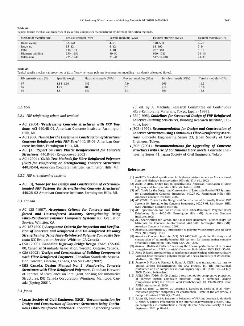
Table A4Typical tensile mechanical properties of glass fibre composites manufactured by different fabrication methods.
Method of manufacture Tensile strength (MPa) Tensile modulus (GPa) Flexural strength (MPa) Flexural modulus (GPa)
Hand lay-up 62–344 4–31 110–550 6–28Spray-up 35–124 6–12 83–190 5–9RTM 138–193 3–10 207–310 8–15Filament winding 550–1380 30–50 690–1725 34–48Pultrusion 275–1240 21–41 517–14,448 21–41
Table A5Typical tensile mechanical properties of glass fibre/vinyl-ester polymer (compression moulding – randomly orientated fibres).
Fibre/matrix ratio (%) Specific weight Flexural strength (MPa) Flexural modulus (GPa) Tensile strength (MPa) Tensile modulus (GPa)
67 1.84–1.90 483 17.9 269 19.365 1.75 406 15.1 214 15.850 1.8 332 15.3 166 15.8
L.C. Hollaway / Construction and Building Materials 24 (2010) 2419–2445 2441
B.2. USA
B.2.1. FRP reinforcing rebars and tendons
� ACI (2004) ‘Prestressing Concrete structures with FRP Ten-dons, ACI 440.4R-04, American Concrete Institute, FarmingtonHills, MI.� ACI (2006) ‘Guide for the Design and Construction of Structural
Concrete Reinforced with FRP Bars’ 440.1R-06, American Con-crete Institute, Farmington Hills, MI.� ACI [3], ‘Report on Fibre Plastic Reinforcement for Concrete
Structures’ 440.R-96 (Re-approved 2002).� ACI (2004), ‘Guide Test Methods for Fibre-Reinforced Polymers
(FRP) for reinforcing or Strengthening Concrete Structures’440.3R-04, American Concrete Institute, Farmington Hills, MI.
B.2.2. FRP strengthening systems
� ACI [3], ‘Guide for the Design and Construction of externally-bonded FRP Systems for Strengthening Concrete Structures’,440.2R-02 American Concrete Institute, Farmington Hills, MI.
B.3. Canada
� AC 125 (1997), Acceptance Criteria for Concrete and Rein-forced and Un-reinforced Masonry Strengthening UsingFibre-Reinforced Polymer Composite Systems ICC EvaluationService, Whittier, CA.� AC 187 (2001) Acceptance Criteria for Inspection and Verifica-
tion of Concrete and Reinforced and Un-reinforced MasonryStrengthening Using Fibre-Reinforced Polymer Composite Sys-tems ICC Evaluation Service, Whittier, CA.Canada� CSA (2000), ‘Canadian Highway Bridge Design Code’, CSA-06-
00, Canadian Standards Association, Toronto, Ontario, Canada.� CSA (2002), ‘Design and Construction of Building Components
with Fibre-Reinforced Polymers’, Canadian Standards Associa-tion, Toronto, Ontario, Canada, CSA S806-02 (2002).� ISIS Canada, Design Manual No. 3, ‘Reinforcing Concrete
Structures with Fibre-Reinforced Polymers’, Canadian Networkof Centres of Excellence on Intelligent Sensing for InnovativeStructures, ISIS Canada Corporation, Winnipeg, Manitoba, Can-ada (Spring 2001).
B.4. Japan
� Japan Society of Civil Engineers (JSCE), ‘Recommendation forDesign and Construction of Concrete Structures Using Contin-uous Fibre-Reinforced Materials’, Concrete Engineering Series
23, ed. by A. Machida, Research Committee on ContinuousFibre-Reinforcing Materials, Tokyo, Japan, (1997).� BRI (1995), Guidelines for Structural Design of FRP Reinforced
Concrete Building Structures, Building Research Institute, Tsu-kuba, Japan� JSCE (1997), Recommendation for Design and Construction of
Concrete Structures using Continuous Fibre-Reinforcing Mate-rials. Concrete Engineering Series 23, Japan Society of CivilEngineers, Tokyo.� JSCE (2001), Recommendations for Upgrading of Concrete
Structures with Use of Continuous Fibre Sheets. Concrete Engi-neering Series 41, Japan Society of Civil Engineers, Tokyo.
References
[1] AASHTO. Standard specification for highway bridges. American Association ofState and Highway Transportation Officials. 17th ed.; 2002.
[2] AASHTO LRFD. Bridge Design Specifications. American Association of StateHighway and Transportation Officials. 3rd ed.; 2004.
[3] ACI. Guide for the Design and Construction of Externally Bonded FRP Systemsfor Strengthening Concrete Structures. 440.2R-02. Farmington Hills (MI):American Concrete Institute; 2002.
[4] ACI (2008), ‘Guide for the Design and Construction of Externally Bonded FRPSystems for Strengthening Concrete Structures’, 440.2R-08. Farmington Hills(MI): American Concrete Institute.
[5] ACI. Specification for Construction with Fiber-Reinforced Polymer (FRP)Reinforcing Bars. 440.5-08. Farmington Hills (MI): American ConcreteInstitute; 2008.
[6] ACI. Specification for Carbon and Glass Fiber-Reinforced Polymer (FRP) BarMaterials for Concrete Reinforcement, 440.6-08. Farmington Hills (MI):American Concrete Institute; 2008.
[7] Aklonia JJ, MacKnight WJ. Introduction to polymer viscoelasticy. 2nd ed. NewYork (NY): Wiley; 1983.
[8] American Concrete Institute (ACI), ACI 440,2R-02: guide for the design andconstruction of externally-bonded FRP systems for strengthening concretestructures. Farmington Hills, Mich, USA: ACI; 2002.
[9] Anania L, Badala A, Failla G. ‘Increasing the flexural performance of RC beamsstrengthened with CFRP materials’. Construct Build Mater 2005;19(1):55–61.
[10] Arora D. Rapid strengthening of reinforced concrete bridge with mechanicallyfastened-fibre reinforced polymer strips’ MS Thesis, University of Wisconsin-Madison, USA; 2003.
[11] Asprone D, Prota A, Parretti R, Nanni A. GFRP radar-transparent barriers toprotect airport infrastructures: the SAS project’. In: 4th internationalconference on FRP composites in civil engineering (CICE 2008), 22–24 July2008, Zurich, Switzerland.
[12] ASTM D6641/D6641M-09. Standard test method for compressive propertiesof polymer matrix composite materials using a combined loadingcompression (CLC) test fixture. West Conshohocken, PA, 19428-2959, USA;ASTM International; 2009.
[13] Bakis CE, Bank LC, Brown VL, Cosenza E, Davalos JF, Lesko JJ, et al. Fiber-reinforced polymer composites for construction – state-of-the-art review. JCompos Construct 2002;6(2):73–87.
[14] Balazs GL, Borosnyoi A. Long-term behaviour of FRP. In: Cosenza E, ManfrediG, Nanni A, editors. Proceedings of the international workshop, at Carri, Italy,on composites in construction: a reality. Reston: American Society of CivilEngineers; 2001. p. 84–91.
2442 L.C. Hollaway / Construction and Building Materials 24 (2010) 2419–2445
[15] Bank LC. Mechanically-fastened FRP (MF-FRP) – a viable alternative forstrengthening RC members. In: Seracino R, editor. Proceedings of the FRPcomposites in civil engineering – CICE 2004. Leiden/London/New York/Philadelphia/Singapore: A.A. Balkema Publishers; 2004.
[16] Bank LC, Arora D. Analysis and design of RC beams with mechanicallyfastened FRP(MF-FRP) strips. ACI Struct J, in preparation.
[17] Bank LC, Gentry RT. Accelerated test methods to determine the long-termbehaviour of FRP composite structures: environmental effects. J Reinf PlastCompos 1995;14:559–87.
[18] Bank LC, Gentry RT, Barkatt A, Prian L, Wang F, Mangla SR. Accelerated agingof pultruded glass/vinylester rods. In: Proceeding 2nd internationalconference on fibre composites in infrastructure (ICCI), vol. 2; 1998 p. 423–37.
[19] Bank LC, Borowicz DT, Arora D, Lamanna AJ. Strengthening of concrete beamswith fasteners and composite material strips – scaling and anchorage issues.US Army Corps of Engineers. Draft Final Report, Contract Number DACA42-02-P-0064; 2003.
[20] Bank LC, Arora D, Borowicz DT, Oliva M. Rapid strengthening of reinforcedconcrete bridges. Wisconsin Highway Research Program, Report Number 03-06; 2003. 166 pages.
[21] Barnes RA, Mays GC. Strengthening of reinforced concrete beams in shear bythe use of externally bonded steel plates: part 1 – experimental programme’.Construct Build Mater 2006;20(6):396–402.
[22] Basler M, Mungal B, Fan S. Strengthening of structures with the Sika Carb0Durcomposite strengthening systems. In: Teng JG, editor. Proceedings of theinternational conference on FRP composites in civil engineering – CICE 2001.Oxford, England: Elsevier Science; 2001. p. 253–62.
[23] BD 90/05 – Design of FRP bridges and highway structures, design manual forroads and bridges, vol. 1, Section 3, Part 17; 2005.
[24] BD67/96 Enclosure of Bridges – UK Highways Agency – Standard and AdviceNotes, – Standard and Advice Notes, The Highways Agency, Southwark Street,London; 1996.
[25] BD37/01. Enclosure of bridges. Design manual for roads and bridges,Highways Agency, London; 1988.
[26] Berry DBS. Tests on full size plastics panel components. In: Hollaway Leonard,editor. The use of plastics for load bearing and infill panels. Croydon: PublishersManning Rapley Publishing Limited; 1974 [chapter 9].
[27] Binici B. An analytical model for stress–strain behaviour of confined concrete.Eng Struct 2005;27(7):1040–51.
[28] Bisby LA, Green MF, Kodur VKR. Fire endurance of FRP-confined concrete: testresults and model evaluation. ACI Struct J 2005;102(6):883–91.
[29] Bogas JA, Gomes A. Analysis of the CFRP flexural strengthening reinforcementapproaches proposed in fib bulletin 14 2008; 22(10).
[30] Brundtland GH. World commission on environment and development, ourcommon future, report. Oxford: Oxford University Press; 1987.
[31] Canning L, Hollaway L, Thorne AM. Manufacture, testing and numericalanalysis of an innovative polymer composite/concrete structural unit. ProcInst Civil Eng Struct Bridges 1999;134:231–41.
[32] Canning L, Hodgson J Karuna, R, Luke S, Brown P. Progress of advancedcomposites for civil infrastructure. In: Proceedings of the ICE, structures andbuildings, vol.160, Issue 6; 2007. p. 307–15.
[33] Canning L. Mount pleasant FRP bridge deck over M6 motorway. In:Proceedings of the 4th international conference on FRP composites in civilengineering (CICE 2008), 22nd–24th July 2008, Zurich, Switzerland; p243 [6pages].
[34] Caron J-F, Julich S, Baverel O. Self-stressed bowstring footbridge in FRP.Compos Struct 2009;89(3):489–96 [July].
[35] Casadei P, Agneloni E. Elastic systems for dynamic retrofitting of structures.Paper 15B, Cobrae Conference 2007 – benefits of composites in civilengineering, University of Stuttgart 28–30th March 2007. Stuttgart(Germany): Pub. Itke, University of Stuttgart; 2007.
[36] Ceroni F, Cosenza E, Gaetano M, Pecce M. Durability issues of FRP rebars inreinforced concrete members. Cement Concrete Compos 2006;28(10):857–68.
[37] Cessna LC. Stress–time superposition for creep data for polypropylene andcoupled glass reinforced polypropylene. Polym Eng Sci 1971;13:211–9 [May].
[38] Cheng R, Yang H. Application of time–temperature superposition principle topolymer transient kinetics. J Appl Polym Sci 2005;99(4):1767–72.
[39] Chowdbury EU, Bisby LA, Green MF, Kodur VKR. Performance in fire ofinsulated FRP-wrapped reinforced concrete columns. In: Proceedings of the4th international workshop: structures in fire, Aveiro, Portugal; 2006. p. 791–802
[40] Chowdbury EU. Performance in fire of reinforced concrete tee beamsstrengthened with externally bonded fiber-reinforced polymer sheets. MSc.Thesis, Department of Civil Engineering, Queen’s University, Kingston,Ontario, Canada; 2005.
[41] Chowdbury EU, Bisby LA, Green MF, Kodur VKR. Residual behaviour of fire-exposed reinforced concrete beams pre-strengthened in flexure with fibre-reinforced polymer sheets. J Compos Construct 2008:61–8 (Jan/Feb.).
[42] Clarke JL. Quality assurance/quality control, maintenance and repair. In:Hollaway LC, Teng JG, editors. Strengthening and rehabilitation of civilinfrastructures using advanced fibre/polymer composites. Cambridge:Woodhead Publishing; 2008. p. 323–51 [chapter 12].
[43] Colombi P, Bassetti A, Nussbaumer A. Crack growth induced delamination onsteel members reinforced by prestressed composite patch. J Fatigue Fract EngMater Struct 2003;26(5):429–37.
[44] Composite Advantage Newsletter. Composite advantage builds new drop-in-place FRP superstructure press release 1st May; 2008.
[45] Concrete Repair Manual. Second ed., vol.1. Farmington Hills (MI): ACI; 2003.p. 915–24.
[46] Concrete Society. Strengthening concrete structures using fibre compositematerials: acceptance, inspection and monitoring. TR57, Camberley, UK;2003.
[47] Concrete Society. Design guide for strengthening concrete structures usingfibre composite materials. TR 55, 2nd ed. Camberley, UK; 2004.
[48] Constable PA. Bridge modification approach – a value for money approach’Paper 3. In: Proceedings of stronger and safer Bridges – Bridge modification 2,21.
[49] Correia JR, Branco FA, Ferreira JG. Fire protection of GFRP pultruded profilesfor floors of buildings. In: 4th international conference on FRP composites incivil engineering. EMPA; 2009. p. 211.
[50] Daly AF, Duckett WA. The design and testing of an FRP highway bridge deck. JRes 2002;5(3) [Transport Research Laboratory, Crowthorne, UK].
[51] De Lorenzis L, Nanni A. Characterisation of FRP rods as near-surface mountedreinforcement. J Compos Construct 2001;5(2):114–21.
[52] De Lorenzis L, Nanni A. Shear strengthening of RC beams with near surfacemounted FRP rods. ACI Struct J 2001;98(1):60–8.
[53] De Lorenzis L, Micelli F, La Tegola A. Passive and active near surface mountedFRP rods for flexural strengthening of RC beams. In: Proceedings of ICCI’02,San Francisco, USA; 2002.
[54] De Lorenzis L, Teng JG. Near-surface mounted reinforcement: an emergingtechnique for structural strengthening. Compos Part B: Eng 2007;38(2):119–43.
[55] De Lorenzis L, Stratford T, Hollaway LC. Structurally deficient civil engineeringinfrastructure: concrete, metallic, masonry and timber structures. In: HollawayLC, Teng JG, editors. Strengthening and rehabilitation of civil infrastructuresusing fibre-reinforced polymer (FRP) composites. Cambridge: WoodheadPublishing; 2008 [chapter 1].
[56] Deniaud C, Cheng JJR. Shear behaviour of RC T-beams with externally bondedfiber reinforced polymer sheets. ACI Struct J 2001;93(3):386–94.
[57] Deniaud C, Cheng JJR. Review of design methods for reinforced concretebeams strengthened with fiber reinforced polymer sheets. Can J Civil Eng2001;28:271–81.
[58] Deniaud C, Cheng JJR. Reinforced concrete t-beams strengthened in shearwith forced fiber polymer sheets. J Concrete Construct, ASCE 2003;7(4):302–10.
[59] Deskovic N, Triantafillou TC. Innovative design of FRP combined withconcrete: short-term behaviour. J Struct Eng 1995;121(7):1069–78.
[60] Ebead UA, Marzouk H. Fiber-reinforced polymer strengthening og two-wayslabs. ACI Struct J 2004;101(5):650–9.
[61] Egan J. Rethinking construction. Report commissioned by John Prescott, thedeputy Prime Minister in July 1998. Source: Rethinking Construction; 1998.
[62] El-Hacha R, Rizkalla SH. Near-surface-mounted fibre-reinforced polymerreinforcements for flexural strengthening of concrete structures. ACI Struct J2004;101(5):717–26.
[63] El-Refaie SA, Ashour AF, Garrity SW. Sagging and hogging strengthening ofcontinuous reinforced concrete beams using CFRP sheets. ACI Struct J2003;100(4):446–53.
[64] Elsayed W, Ebead UA, Neale KW. Interfacial behavior and debonding failuresin FRP-strengthened concrete slabs. J Compos Construct 2007;11(6):619–28.
[65] Erki MA, Heffernan PJ, Reinforced concrete slabs externally strengthened withfiber reinforced plastic materials. In: L. Taerwe, editor. Proceedings of thesecond international RILEM symposium FRPRCS-2. Belgium: University ofGhent; 1995. p. 509–16.
[66] Eshwar N, Ibell T, Nanni A. CFRP strengthening of concrete bridges withcurved soffits. In: Forde MC, editor. Proceedings of structural faults + repair2003, London, UK. CD-ROM, 2003. 10 pp.
[67] Faber Maunsell. FRP footbridge in place. Reinf Plastics 2003;47(6):9 [June].[68] Fam AZ, Rizkalla SH. Confinement model for axially loaded concrete confined
by circular fiber-reinforced polymer tubes. ACI Struct J 2001;98(4):451–61.
[69] Fam AZ, Rizkalla SH. Behavior of axially loaded concrete-filled circular fiber-reinforced polymer tubes. ACI Struct J 2001;98(3):280–9.
[70] Fanning P, Kelly O. Shear strengthening of reinforced concrete beams: anexperimental study using CFRP plates. In: Forde MC, editor. Proceedings ofthe 8th international conference on structural faults and repair. Edinburgh(UK): Engineering Technics Press; 1999.
[71] Federation Internationale du Beton, fib Task Group 9.3. Externally bonded FRPreinforcement for RC structures. FIB, Lausanne; 2001.
[72] fib Bulletin 14. Design and use of externally bonded FRP reinforcement for RCStructures. Federation Internationale du Beton; 2001.
[73] Garden HN, Shahidi EG. ´The use of advanced composite laminates asstructural reinforcement in a historical building. In: Shenoi RA, Moy SJ,Hollaway LC, editors. Proceedings of the international conference ‘advancedpolymer composites for structural applications in construction. University ofSouthampton, UK, 15–17 April; 2002. p. 457–65.
[74] Gordon SR, May IM. Precast deck systems for steel-concrete compositebridges. In: Proceedings of the institution of civil engineers, BridgeEngineering 160, March 2007, Issue BE1; 2007 p. 25–35.
[75] GRP road bridge .An operational response to ageing infrastructure. ECComposites magazine, November/December; 2008, (45), 64.
[76] Guyson Manual of blast media’, Guyson data sheets; 1989.

L.C. Hollaway / Construction and Building Materials 24 (2010) 2419–2445 2443
[77] Hackman I, Hollaway LC. Epoxy-layered silicate nanocomposites in civilengineering. Composites Part A 2006;37(8):1161–70.
[78] Haque A, Shamsuzzoha M, Hussain F, Dean D. S2-Glass/epoxy polymernanaocomposites: manufacturing, structures, thermal and mechanicalproperties. J Compos Mater 2003;37(20):1821–37.
[79] Harajli MH, Soudki KA. Shear strengthening of interior slab-columnconnections using carbon fibre-reinforced polymer sheets. J ComposConstruct 2003;7(2):145–53.
[80] Harries KA, Kharel G. Experimental investigation of the behaviour of variablyconfined concrete. Cem Concr Res 2003;33(2003):873–80.
[81] Harries KA, Porter ML, Busel JP. FRP materials and concrete – research needs.Concrete Int 2003;25(10):69–74.
[82] Hassan T, Rizkalla S. Flexural strengthening of post-tensioned bridge slabswith FRP systems. PCI J 2002;47(1):76–93.
[83] Hastak M, Halpin DW, Hong T. Constructability, maintainability, andoperability of fiber reinforced polymer (FRP) Bridge Deck Panels. DOT FinalReport (FHWA/IN/JTRP-2004/15); 2004.
[84] Head P. The world’s first advanced composite road bridge. In: Symposium on– short and medium span bridges, Calgary, Canada; 1994.
[85] Head P. GRP Walkway membranes for bridge access and protection. Paperdelivered to 13th RPG Congress, British Plastic Federation, London; 1982.
[86] Heinberg R, Mander J. Searching for a miracle: net energy’ limits and the fateof industrial society. Post Carbon Institute and International Forum onGlobalization Nov 13; 2009.
[87] Hollaway LC. Polymer composites for civil and structuralengineering. Glasgow: Blackie Academic and Professional; 1993.
[88] Hollaway LC, Mays GC. Structural strengthening of concrete beams usingunstressed composite plates. Strengthening of reinforced concrete structures,– using externally-bonded FRP composites in structural and civilengineering. Cambridge, England: Pub. Woodhead Publishing Ltd.; 1999[Chapter 4].
[89] Hollaway LC, Leeming MB. Strengthening of reinforced concrete structures –using externally-bonded FRP composites in structural and civilengineering. Cambridge, England.: Pub. Woodhead Publishing Ltd.; 1999.
[90] Hollaway LC, Head PR. Advanced polymer composites and polymers in thecivil infrastructure. Oxford: Pub. Elsevier; 2001.
[91] Hollaway LC. The evolution of and the way forward for advanced polymercomposites in the civil infrastructure. Construct Build Mater 2003;17(6–7):365–78.
[92] Hollaway LC. Fibre-reinforced polymer composite structures and structuralcomponents: current applications and durability issues. In: Karbhari Vistasp,editor. Durability of composites for civil structural applications. Cambridge,UK: Publishers Woodhead Publishing; 2007 [chapter 10].
[93] Hollaway LC. Fibre-reinforced polymer (FRP) composites used inrehabilitation. In: Hollaway LC, Teng JG, editors. Chapter 2 of‘Strengthening and rehabilitation of civil infrastructures using fibre-reinforced polymer (FRP) composites. Cambridge UK, USA: Pub. WoodheadPublishing, CRC Press; 2008.
[94] Hollaway LC. Case studies. In: Hollaway LC, Teng JG, editors. Strengtheningand rehabilitation of civil infrastructures using fibre-reinforced polymer(FRP) composites. Cambridge: Woodhead Publishing; 2008 [chapter 13].
[95] Hollaway LC. Advanced fibre polymer composite structural systems used inbridge engineering. In: Parke G, Hewson N, editors. ICE manual of bridgeengineering. London: Thomas Telford; 2008. p. 503–30.
[96] Hollaway, Teng. Strengthening and rehabilitation of civil infrastructures usingfibre-reinforced polymer (frp) composites. Woodhead Publishing; 2008.
[97] Hollaway LC, Chen JF. Sub-editors to section 7 of ICE manual of constructionmaterials. ICE; 2009.
[98] Hollaway LC. Advanced polymer composites. In: Hollaway LC, Chen JF, subeditors, Forde M, editor. ICE manual of construction material. Thomas Telford,London; 2009 [Chapters 51 and 52, of Section 7].
[99] Hollaway LC. Review of the generation of solar electricity – with specialreference to a reinforced thermoplastics solar support system ASCE J ComposConstruct, in press.
[100] Holliday L, White JW. The stiffness of polymers in relation to their structure.In: Pure and applied chemistry, international symposium onmacromolecules, Leiden, The Netherlands 31 August 31st 4th September170, vol. 26, Issue 3; 1971. p. 545–82.
[101] Hongbo L, Zhao X-L, Al-Mahaidi R. Cracked steel plate with CFRP patch.Compos Struct 2009;91(1):74–83.
[102] Hulatt J, Hollaway L, Thorne A. Characteristics of composite concrete beams.In: Ryall MJ, Parke GAR, Harding JE, editors. Bridge management – 4inspection maintenance assessment and repair. Thomas Telford; 2000. p.83–491.
[103] Hulatt J, Hollaway LC, Thorne AM. Developing the use of advanced compositematerials in the construction industry. In: Proceedings of the internationalconference, FRPRC-5, Cambridge, UK; July 2001.
[104] Hulatt J, Hollaway L, Thorne A. The use of advanced polymer composites toform an economic structural unit. Int J Construct Build Mater2003;17(1):55–68.
[105] Hulatt J, Hollaway L, Thorne A. Short term testing of a hybrid T-beam madefrom a new prepreg material. ASCE J Compos Construct 2003;7(2):135–45.
[106] Hulatt J, Hollaway LC, Thorne AM. A novel advanced polymer composite/concrete structural element. In: Proceedings of the institution of civilengineers. Special issue: advanced polymer composites for structuralapplications in construction; February 2004, p. 9–17.
[107] Hull D, Clyne TW. An introduction to composite materials. CambridgeUniversity Press; 1996.
[108] Hutchinson A. Adhesives for externally bonded FRP reinforcement. In:Hollaway LC, Chen JF, sub editors. Mike Forde, editor, ICE manual ofconstruction materials, vol 2. Thomas Telford, London, UK; 2009 [chapter57, Section 7].
[109] Iabucci RD, Sheikh SA, Bayrak o. ‘Retrofit of square concrete columns withcarbon fiber-reinforced polymer for seismic resistance. ACI Struct J2003;100(6):785–94.
[110] Ibell TJ, Silva PF. A theoretical strategy for moment redistribution incontinuous FRP-strengthened concrete structures. In: Hollaway LC,Chryssanthopoulos MK, Moy SSJ, editors. Proceedings of conference ACIC-2004, 20–22nd April 2004, Guildford, Surrey, UK; 2004. p. 144–51.
[111] ISIS Canada. ISIS Canada, Design Manual No. 3, ‘Strengthening ReinforcingConcrete Structures with Externally Bonded Fiber Reinforced Polymers’,Canadian Network of Centers of Excellence on Intelligent Sensing forInnovative Structures, ISIS Canada Corporation, Winnipeg, Manitoba,Canada (Spring 2001); 2001.
[112] Jones RL, Chandler HD. Strength loss in E-glass fibres after exposure toorganics acids. J Mater Sci 1985;20:3325–8.
[113] Klowak C, Memon A, Mufti A. Static and fatigue investigation of secondgeneration steel-free bridge decks. Cement Concrete Compos 2006;28(10):890–7.
[114] Katsuki F. Evaluation of alkaline resistance of fibre reinforcement forconcrete. Thesis submitted to the University of Tokyo for D, Engrg degree;1997 [in Japanese].
[115] Karbhari, Li. A review of durability based safety factors for the use of FRPcomposites in civil infrastructure. In: Fu-Kuo Chang, editor. 10th US–Japanconference on composite materials. Stanford University, Co-organised by Air-force Office of Scientific Research, The American Society for Composites andthe National Science Foundation, 16–18, 2002 Stanford University, Stanford,California; 2002. p. 292–300.
[116] Karbhari VM, Chin JW, Hunston D, Benmokrane B, Juska T, Morgan R, et al.Durability gap analysis for fiber-reinforced polymer composites in civilinfrastructure. J Compos Construct 2003;7(3):238–47.
[117] Karbhari VM. Durability of FRP composites for civil infrastructure myth,mystery or reality. Adv Struct Eng 2003;6(3):243–56.
[118] Karbhari VM. Fabrication, quality and service-life issues for composites incivil engineering. In: Karbhari VM, editor. Durability of composites for civilstructural applications. Cambridge, England: Woodhead Publishing; 2007[chapter 2].
[119] Katz A. Bond to concrete of FRP rebars after cyclic loading. J ComposConstruct 2000;4(3):137–44.
[120] Kazunori F, Mindness S, Xu H. Analytical model for concrete confined withfiber reinforced polymer concrete. ASCE J Compos Construct 2004;8(4):341–51.
[121] Keller T. Recent all-composite and hybrid fibre-reinforced polymer bridgesand buildings. J Prog Struct Eng Mater 2001;3(2):132–40.
[122] Keller T, Tracy C, Huge E. Fire endurance of loaded and liquid-cooled GFRPslabs for construction. Composites: Part A 2006;37(7):1055–67.
[123] Kendall D. Building the future with FRP composites. Reinf Plast2007;51(5):31–3. 26–9.
[124] Khennane A. A new design concept for a hybrid FRP-high strength concretebeam for infrastructure applications. In: 4th international conference on FRPcomposites in civil engineering (CICE 2008), 22–24 July 2008, Zurich,Switzerland; 2008.
[125] Kim D-H. Composite structures for civil and architecturalengineering. London, Glasgow, Weinheim, New York, Tokyo, Melbourne,Madras: E & FN Spon; 1995.
[126] Kim RY. Fatigue strength. In: Dostal CA, editor. Composites engineeredmaterials handbook, vol 1. Metals Park (OH): ASM International; 1987. p.436–44.
[127] Kinloch AJ. Adhesion and adhesives: science and technology. London:Chapman and Hall; 1987.
[128] Mirmiran A, Shahawy M, Samaan M, Echary H, Mastrapa JC, Pico C. Effect ofcolumn parameters on FRP confined concrete. J Compos Construct1998;2(4):175–85.
[129] Klowak C, Eden R, Mufti AA, Elkholy I, Tadros G, Loewen E. First application ofsecond-generation steel-free slabs for bridge rehabilitation. In: Watanabe E,Frangopol DM, Utsunomiya T, editor. Bridge management, safety,management and cost. Proceedings of the 2nd international conferenceIABMAS. London (UK): Taylor and Francis Group plc.; 2004. p. 453–4.
[130] Kuang KSC, Cantwell WJ. The use of conventional optical fibres and fibreBragg gratings for damage detection in advanced composite structures – areview. Appl Mech, Rev 2003;56:493–513.
[131] Kuang KSC, Quek ST, Koh CG, Cantwell WJ, Scully. Plastic optical fibre sensorsfor structural health monitoring: a review of recent progress. J Sensors2009;2009:1–13 [Article ID 312053].
[132] Lam L, Teng JG. Strength models for fiber-reinforced plastic-confinedconcrete. ASCE J Struct Eng 2002;128(5):612–23.
[133] Lam L, Teng JG. Design-oriented stress–strain model for FRP-confinedconcrete. Construct Build Mater 2003;17(6 and 7):471–89. September–October.
[134] Latham M. Constructing the team. The final report of the government/industry review of procurement and contractual arrangements in the UKconstruction industry HMSO, London; 1994.
2444 L.C. Hollaway / Construction and Building Materials 24 (2010) 2419–2445
[135] Le Baron P, Wang Z, Pinnavaia. Polymer-layered silicate nanocomposites. AnOverview Appl Clay Sci 1999;15:11–29.
[136] Lee SU, Hong K-J. Experiencing more composite-deck bridges and developinginnovative profile of snap-fit connections. Paper 10B, Cobrae Conference2007 – Benefits of Composites in Civil Engineering, University of Stuttgart28–30th March 2007 – Stuttgart, Germany, Pub. Itke, University of Stuttgart;2007.
[137] Lee SL, Jain R. The role of FRP composites in a sustainable world. CleanTechnol Environ Policy 2009;11(3):247–9.
[138] El Sayed W, Ebead UA, Neale KW. Interfacial behavior and debonding failuresin FRP-strengthened concrete slabs. J Compos Construct 2007;11(6):619–28.
[139] Longworth J, Bizindavyi L, Wight RG, Erki A. Prestressed CFRP sheets forstrengthening two-way slabs in flexure. In: El-Badry M, Dunaszegi L, editors.Advanced composite materials in bridges and structures. Canadian Societyfor Civil Engineering; 2004. p. 8.
[140] Li A, Sagues A, Poor N. In-situ leaching investigation of pH and nitriteconcentration in concrete pore solution. Cement Concrete Res 1999;29:315–21.
[141] Limam o, Foret G, Ehrlacher A. Reinforced concrete two-way slabsstrengthened with CFRP strips: experimental study and a limit analysisapproach. J Compos Construct 2003;60:467–71.
[142] Longinow A, Krauthammer T, Mohammadi J. Research needed to resistterroristattacks – section on dynamics of structures. In: Proceedings of thestructures congress, Orlando, Florida, ASEC; 1987. p. 712–20.
[143] Liu W, Hoa S, Pugh H. Epoxy–clay nanocomposites: dispersion, morphologyand performance. Compos Sci Technol 2005;65:307–16.
[144] Lu XZ, Teng J, Ye LP, Jiang JJ. Intermediate crack debonding in FRP-strengthened RC beams: FE analysis and strength model. J ComposConstruct 2007;11(2):161–74.
[145] Lui I, Oehlers DJ, Seracino R. Parametric studies of intermediate crack (IC)debonding on adhesively plated beams. In: Seracino R, editor. Proceedings ofthe international conference on FRP composites in Civil Engineering – CICE2004. Leiden/London/New York/Singapore: A.A.Balkema Publishers; 2004.
[146] Luke S, Canning L, Brown P, Kundsen E, Olofsson I. The development of anadvanced composite bridge decking system – project ASSET. Struct Eng Int2002;12(2).
[147] Luke S, Canning L. Strengthening highways and railway bridge structures withFRP composites–case studies. In: Advanced polymer composites for structuralapplications in construction. Proceedings of the second internationalconference, held at the University of Surrey, Guildford, UK, on 20–22 April,2004, Woodhead Publishing Ltd., Cambridge, England; 2004. p. 745–55.
[148] Luke S, Canning L. Strengthening and repair of railway bridges using FRPcomposites. In: Parke GAR, Disney P, editors. Proceedings of the 5thinternational conference on bridge management. University of Surrey,Guildford, UK, 13–15th April; 2005. London: Thomas Telford.
[149] Matthews FL, Rawlings RD. Composite materials: engineering andscience. Cambridge, England: Woodhead Publishing; 1999.
[150] McKenzie, M., (1991), Corrosion protection: The environment created bybridge enclosure, Research Report 293, (1991), from Bridges Division,Structures Group, Road Research Laboratory, Crowthorne, Bib ID 26584.
[151] McKenzie M. The corrosivity of the environment inside the Tees Bridgeenclosure: final year results. Project Report PR/BR/10/93; 1993.
[152] Mertz, D.R. and Gillespie, J.W., (1996). ,Rehabilitation of steel bridge girdersthrough the application of Advanced Composite Materials’, Final Report tothe Transportation Research Board for NCHRP-IDEA Project 11, pp. 30.
[153] Micelli F, Nanni A. Durability of FRP rods for concrete structures. ConstructBuild Mater 2004;18(7):491–503.
[154] Mosallam AS, Chakrabarti PR. Making connection. Civil Engineering, ASCE;1997. p. 56–59 [Editor].
[155] Moy SSJ. FRP composites – life extension and strengthening of metallicstructures. Institution of Civil Engineers; 2001. p. 33–5.
[156] Motavalli M, Czaderski C. FRP composites for retrofitting of existing civilstructures in Europe: state-of-the-art review. Composites and Polycon 2007,American Composites Manufacturers Association, October 17–119th 2007,Tampa, FL, USA; 2007. p. 1–10.
[157] Mouritz AP, Gibson AG. Fire properties of polymer composite materials,Springer, Dordrecht; 2006. p. 394 (ISBN 140253559).
[158] Meier U. Strengthening of structures using carbon fibre/epoxy composites.Construct Build Mater 1995;9(6):341–51.
[159] Meier H, Basler M, Fan S. Structural strengthening with bonded CFRP L-shaped plates. In: Teng JG, editor. Proceedings of the international conferenceon FRP composites in civil engineering – CICE 2001. Oxford (England):publishers Elsevier Science; 2001. p. 263–72.
[160] Meier U. Proposal for a carbon fibre reinforced composite bridge across theStrait of Gibraltar at its narrowest site. In: Proceedings of the institution ofmechanical engineers, Part B: management and engineering manufacture,vol. 201(B2); 1987. p. 73–8.
[161] Meier U. Structural tensile elements made of advanced composite materials.Struct Eng Int 1999;9(4):281–5 [1st November 1999].
[162] Michel L, Ferrier E, Agbossou A, Hamelin P. Flexural stiffness modelling of RCslab strengthened by externally bonded FRP. Composites Part B2009;40(8):758–65.
[163] Mirmiran A, Shahawy M, Nanni A Karbhari VM. Bonded repair and retrofit ofconcrete structures using FRP composites: recommended constructionspecification and processing control manual. NCHRP 514, TransportResearch Board of the National Academies, Washington, DC; 2004. p. 66–74.
[164] Mirmiran A, Shahawy M, Nanni A, Karbhari, Yalim B. Recommendedconstruction specifications and process control manual for repair andretrofit of concrete structures using bonded FRP composites. Report 609National Cooperative Highway Research Program; 2008.
[165] Mirmiran A. Stay-in-place FRP form for concrete columns. Adv Struct Eng2003;6(3):231–41.
[166] Mosallam AS, Mosalam KM. Strengthening of two-way concrete slabs withcomposite laminates. Construct Build Mater 2003;17:43–54.
[167] Mosallam AS. Composites for highway bridges applications: a state-of-the-art review, Paper 7B, cobrae conference 2007 – benefits of composites in civilengineering, University of Stuttgart 28–30th March 2007 – Stuttgart,Germany, Pub. Itke, University of Stuttgart; 2007.
[168] Mouritz AP, Gibson AG. Fire properties of polymer composite materials.London: Springer-Verlag; 2007.
[169] Mufti AA, Jeager LG, Bakht B, Wegner LD. Experimental investigation of FRPslabs without internal steel reinforcement. Can J Civil Eng 1993;20(3):398–406.
[170] Mufti A, Benmokrane B, Boulfiza M, Bakht B, Breyy P. Field study on durabilityof GFRP Reinforcement. International Bridge Deck Workshop, Winnipeg,Manitoba, Canada. April 14–15; 2005.
[171] Mufti, A., Onofrei, M., Benmokrane, B., Banthia, N., Boulfiza, M., Newhook, J.,Bakht, B., Tadros, G. and Brett, P. (2005) ‘Durability of GFRP reinforcedconcrete in field structures. 7th International Symposium on FiberReinforcement for Reinforced Concrete Structures (FRPRCS-7), New OrleansLousiana, USA, November 7–10; 2005.
[172] Mufti A, Onofrei M, Benmokrane B, Banthia N, Boulfiza M, Newhook J, et al.Report on the studies of GFRP durability in concrete from field demonstrationstructures. In: Hamelin et al., editors. Proceedings of the composites inconstruction 2005 – 3rd international conference, Lyon, France, July 11–13;2005.
[173] Mufti AA, Neale KW. State-of-the-art of FRP and SHM applications in bridgestructures in Canada. Compos Res J 2008;2(2):60–9. Spring 2008.
[174] Ngo T, Mendis P, Gupta A, Ramsay J. Review of blast loading. Special edition:Loading on Structures 2007 of the Electronic Journal of StructuralEngineering; 2007.
[175] Nkurunziza G, Debaiky A, Cousin P, Benmokrane B. Durability of GFRP bars: acritical review of the literature. In: Proceedings structural engineeringmaterials, vol. 7; 2005. p. 194–209.
[176] O’Brien TK. Towards a damage tolerance philosophy for composite materialsand structures. In: Garbo SP, editor. Composite materials: testing and design9th volume, ASTM STP 1059. Philadelphia: American Society for TestingMaterials; 1990.
[177] Pešic N, Pilakoutas K. Flexural analysis and design of reinforced concretebeams with externally bonded FRP reinforcement. Mater Struct 2005;38(2):183–92.
[178] Philips LN. Design with advanced composite materials. Berlin, Heidelberg,New York, London, Tokyo: Published for The Design Council by Springer-Verlag; 1989.
[179] Photiou NK, Hollaway LC, Chryssanthopoulos MK. Selection of carbon-fibre-reinforced polymer systems for steelwork upgrading. J Mater Civil Eng2006;18(5):641–9 [September/October].
[180] Pilakoutas K. Composites in concrete construction. In: Gdoutos EE, PilakoutasK, Rodopoulos CA, editors. Failure analysis of industrial compositematerials. New York: McGraw-Hill; 2000. 2000 [chapter 10].
[181] Porter ML, Harries K. Future directions for research in FRP composites inconcrete construction. J Compos Construct 2007;11(3):252–7.
[182] Quantrill RS, Hollaway LC, Thorne AM. Part 1, experimental and analyticalinvestigation of FRP strengthened beam response. Mag Concrete Res1996;48(177):331–42 [December].
[183] Quantrill RS, Hollaway LC, Thorne AM. Part 2, predictions of the maximumplate end stresses of FRP strengthened beams. Mag Concrete Res1996;48(177):343–52 [December].
[184] Ray S, Okamoto M. Polymer-layered silicate nanocomposites: a review frompreparation to processing. Prog Polym Sci 2003;28:1539–641.
[185] Reed CE, Peterman RJ. Evaluation of prestressed concrete girdersstrengthened with carbon fiber reinforced polymer sheets’ ASCE. J BridgeEng 2004;9(2):185–92.
[186] Reitman MA, Yankelevsky DZ. A new simplified method for nonlinearreinforced concrete slabs analysis. ACI Struct J 1997;94(4):399–408.
[187] Righiniotis TD, Aggelopoulos K, Chryssanthopoulos MK. Fracture mechanics2D-FEA of cracked steel plate with a CFRP patch. In: Hollaway LC,Chryssanthopoulos MK, Moy SSJ, editors. Advanced polymer composites forstructural applications in construction (ACIC 2004). CambridgeEngland: Woodhead Publishing Ltd.; 2004.
[188] Roach EC. The manufacturer’s view of the general use of plastics panels asstructural and non-load bearing units. In: Hollaway Leonard, editor. The useof plastics for load bearing and infill panels. Croydon: Manning RapleyPublishing Limited; 1974 [chapter 3].
[189] Saadatmanesh H, Ehsani MR, Jin L. Seismic strengthening of circular bridgepier models with fibre composites. ACI Struct J 1996;93(6):639–47.
[190] Samaan M, Mirmiran A, Shahawy M. Model of confined concrete by fibercomposites. ASCE J Struct Eng 1998;124(9):1025–31.
[191] Schlaich M, Bleicher A. Caron fibre stress-ribbon bridge, Paper 1, cobraeconference 2007 – benefits of composites in civil engineering, University ofStuttgart 28–30th March 2007 – Stuttgart, Germany, Pub. Itke, University ofStuttgart; 2007.

L.C. Hollaway / Construction and Building Materials 24 (2010) 2419–2445 2445
[192] Schnerch D, Rizkalla S. Flexural strengthening of steel bridges with highmodulus CFRP strips. ASCE J Bridge Eng 2008;13(2):192–201. March/April2008.
[193] Seible F, Priestley MJN, Hegemier GA, Innamorato D. Seismic retrofit of RCcolumns with continuous carbon fiber jackets. ASCE J Compos Construct1997;1(2):52–62.
[194] Seim W, Horman M, Karbhari V, Seible F. External FRP post-strengthening ofscaled concrete slabs. J Compos Construct, ASDCE 2001;5(2):67–75.
[195] Sen R, Mullins G, Salem T. Durability of E-glass/vinylester reinforcement inalkaline solution. ASI Struct J 2002;99:369–75.
[196] Sen R. Advances in the application of FRP for repairing corrosion damage.Prog Struct Eng Mater 2003;5(2):99–113.
[197] Sheikh SA, Yao G. Seismic behaviour of concrete columns confined with steeland fiber-reinforced polymers. ACI, Struct J 2002;99(1):72–80.
[198] Smith ST, Teng JG. FRP strengthened RC beams I – review of de-bondingstrength models. Eng Struct 2002;24(4):385–95.
[199] Smith ST, Teng JG. FRP strengthened RC beams II – assessment of de-bondingstrength models. Eng Struc 2002;24(4):397–417.
[200] Spoelstra MR, Monti G. FRP-confined concrete model. ASCE J ComposConstruct 1999;3(3):143–50.
[201] Starr TF, editor. Pultrusion for engineers. Cambridge, UK: WoodheadPublishing Ltd.; 2000.
[202] Stratford T. Aberfeldy Footbridge after 16 years. Paper presented at the Longterm In-service Performance of FRPs in Construction, Seminar 1st July 2008Arup Campus Birmingham, UK; 2008.
[203] Subramaniyan AK, Bing Q, Nakaima D, Sun CT. Effect of Nanoclay oncompressive strength of glass fibre composites. In: Proceedings of the 18thtechnical conference, American Society for Composites, Gainesville, FL, 20–22nd October; 2003.
[204] Sun CT, Chen JK. On the impact of initially stressed composite laminates. JCompos Mater 1985;19(6):490–504.
[205] Takács PE, Kanstad T. Strengthening pre-stressed concrete beams withcarbon fiber reinforced polymer plates. NTNU Report R-9-00, Trondheim,Norway; 2000.
[206] Tavakkolizadeh M, Saadatmanesh H. Strengthening of steel-concretecomposite girders using carbon fibre reinforced polymers sheets. J StructEng ASCE 2003;129(1):30–40.
[207] Teng JG, Chen JF, Smith ST, Lam L. FRP strengthening of RC structures. NewYork, Chichester, England.: John Wiley; 2002.
[208] Teng JG, Lu XZ Ye LP, Jiang JJ. Recent research on intermediate crack de-bonding in FRP-strengthened RC beams. In: Proceeding of 4th internationalconference on advanced composite materials in bridges and Structures,(ACMBS IV), Calgary, Alberta, Canada, July, 2004. CD-ROM; 2004.
[209] Teng JG, Yu T, Wong YL. Behaviour of hybrid FRP-concrete-steel double-skintubular columns. In: Seracino R, editor. FRP composites in civil engineering-CICE 2004. London: Taylor and Francis; 2004. p. 811–8.
[210] Teng JG, Yu T, Wong YL, Dong SL. Hybrid FRP-concrete-steel tubular columns:concept and behaviour. Construct Build Mater 2007;21(4):846–54.
[211] Tastani SP, Pantazopoulou SJ. Detailing procedures for seismic rehabilitationof reinforced concrete members with fiber reinforced polymers. Eng Struct2008;30(2):450–61.
[212] TGP. Birse Rail and TGP complete the UK railway network’s forest vehiclecarrying FRP bridge deck over a railway. Newslett; March 2008.
[213] Triantafillou, TC, Meier U. Innovative design of FRP combined withconcrete. In: Proceedings of the 1st international conference on advancedcomposites for bridges and structures (ACMBS), Sherbrooke, Quebec; 1992.p. 491–99.
[214] Triantafillou TC. Composite materials for civil engineering construction. In:Proceedings of the first Israeli workshop on composite materials for civilengineering construction, Haifa, Israel; May 1995. p. 17–20.
[215] Ushakov AE, Dubinsky SV, Ozerov SN. FRP components for bridgesuperstructures: status and future projects - Russian perspective. In: 5thinternational engineering and construction conference IECC, 27–29 August2008, Irvine, CA, USA.
[216] Uomoto T, Nishimura T. Determination of Aramid, Glass and Carbon Fibresdue to alkali, acid and water in different temperatures. In: Proceedings 4thinternational symposium, FRPRCS-4, ACI SP-188, American ConcreteInstitute; 1999. p. 515–22.
[217] Uomoto T. Durability considerations for FRP reinforcements. In: Burgoyne CJ,editor. Proceedings of 5th International Conference on fibre-reinforcedplastics for reinforced concrete structures. Cambridge, UK; 2001.
[218] Uomoto T. Development of new GFRP with high alkali resistivity. In:Proceedings of 4th international conference on advanced compositematerials in bridges and structures ACMBS-IV, Calgary, Alberta; 2004.
[219] Utraki A. Clay containing polymeric nanocomposites, vol. 1. RapraTechnology Ltd.; 2004. p. 419.
[220] van Ooij WJ, Zhu D, Stacy M, Seth A, Mugada T, Gandhi J, et al. Corrosionprotection properties of organofunctional silanes – an overview. Tsinghua SciTechnol 2005;10(6):639–64.
[221] Xiao Y, Ma R. Seismic retrofit of RC circular columns using prefabricatedcomposite jacking. ASCE, J Struct Eng 1997;123(10):1357–64.
[222] Xiao Y, Wu H. Compressive behavior of concrete confined by carbon fibercomposite jackets. ASCE J Mater Civil Eng 2000;12(2):139–46.
[223] Xiao Y. Applications of FRP composites in concrete column. Adv Struct Eng2004;7(4):335–43.
[224] Yamaguchi T. Deterioration due to ultraviolet radiation and the creep failureof FRP rods. D. Engrg thesis, University of Tokyo; 1998 [in Japanese].
[225] Zhang C, Canning L. A successful model for introducing non-conventionalmaterials in construction. In: Proceedings of the 11th internationalconference on non-conventional materials and technologies (NOCMAT2009) 6–9 September 2009, Bath, UK; 2009.
[226] Zeris CA. Experimental investigation of strengthening of non ductile RCbeams using FRP. In: Proceedings of the 8th US national conference onearth-quakes, 18–22nd April 2006, San Francisco, California, USA; 2006.11p.
[227] Zhou G, Sim LM. Damage detection and assessment in fibre-reinforcedcomposite structures with embedded fibre optic sensors-review. SmartMater Struct 2002;11(6):925–39.
[228] Zhou Y, Lee L. Nanoclay and Long fibre reinforced composites based on epoxyand phenolic resins. ANTEC 2003:2094–8.
[229] Maruyama K, Ueda T. JSCE design recommendations for upgrading of RCmembers by FRP sheet. In: FRPRCS-5—fibre-reinforced plastics for reinforcedconcrete structures, UK; 2001.
[230] Mufti AA, Jeager LG, Bakht B, Wegner LD. Experimental investigation of FRCslabs without internal steel reinforcement. Can J Civil Eng 1993;20(3):398–406.