a requirement elicitation tool for gathering specifications ... · a requirement elicitation tool...
TRANSCRIPT

A Requirement Elicitation Tool for Gathering
Specifications for Data Migration
Matthew Robertshaw
Computing (with Industry)
Session (2007/2008)
The candidate confirms that the work submitted is their own and the appropriate credit has been given
where reference has been made to the work of others.
I understand that failure to attribute material which is obtained from another source may be considered
as plagiarism.
(Signature of student)

Summary
The use of web surveys to gather data from individuals is a common practice in today’s society. As
such, surveys are used by many organisations and groups as anelicitation technique for gathering views
and opinions within many domains and fields of endeavour. Currently tools do exist to facilitate the
creation of simple web surveys by allowing designers to formulate a survey with a set of pre-defined
questions, which are then answered by other individuals. However a new challenge arises when pre-
cursive and successive conditions are defined to determine which question is displayed next, given a
previous answer. Furthermore, to facilitate this process adynamic method of loading questions onto the
screen is required to prepare the application for the next response.
The demand for such an elicitation tool exists within the Computer Sciences Corporation (CSC)
who are currently contracted by the UK government and working collaboratively with the National
Health Service (NHS) to upgrade the current NHS IT infrastructure. By providing CSC with a solution
and using it as a basis for the general development of a dynamic elicitation tool, the project aims to
implement an application to enable the customisable creation and answering of a dynamic web survey
through the use of precursive and/or successive constraints.
i

Acknowledgements
First of all I would like to thank my project supervisor Dr. Brandon Bennett for his invaluable advice
during the development of the algorithm used in the project,as well his patience and support throughout
the year. Extended thanks go to my assessor Dr. Natasha Shakhlevich for her suggestions and advice
over the last year, both of whom I have enjoyed working with.
I would also like to thank the School of Computing support team, more specifically Savio Pirondini
and Ollie Clark for their help in setting up my web application and database on the schools web servers.
Furthermore many thanks go to my client and friend Dr. William Thirsk–Gaskill of the Computer
Sciences Corporation (CSC) as without his vast experience and foresight this project would not have
come to light.
Further thanks must go to Dr. Mark Walkley, my personal tutor, for his friendly advice and support
over the last four years whilst studying at the University ofLeeds.
Finally, I would like to thank my friends and family for theirsupport, patience and encouragement
this year, it’s beenverymuch appreciated.
ii

Contents
1 Introduction 1
1.1 Aim . . . . . . . . . . . . . . . . . . . . . . . . . . . . . . . . . . . . . . . . . . . . 1
1.2 Structure of Report . . . . . . . . . . . . . . . . . . . . . . . . . . . . . . .. . . . . 1
1.3 Objectives . . . . . . . . . . . . . . . . . . . . . . . . . . . . . . . . . . . . . .. . . 2
1.4 Minimum Requirements . . . . . . . . . . . . . . . . . . . . . . . . . . . . .. . . . 2
1.5 Schedule . . . . . . . . . . . . . . . . . . . . . . . . . . . . . . . . . . . . . . . .. . 2
2 Methodologies and Technologies 3
2.1 Methodologies . . . . . . . . . . . . . . . . . . . . . . . . . . . . . . . . . . .. . . 3
2.1.1 SSM (Soft Systems Methodology) . . . . . . . . . . . . . . . . . . .. . . . . 3
2.1.2 SSADM (Structured Systems Analysis and Design Method) . . . . . . . . . . 4
2.1.3 USDP (Unified Software Development Process) . . . . . . . .. . . . . . . . . 5
2.1.4 MoSCoW Prioritisation Technique . . . . . . . . . . . . . . . . .. . . . . . . 6
2.2 Technologies . . . . . . . . . . . . . . . . . . . . . . . . . . . . . . . . . . . .. . . 7
2.2.1 Standalone vs. Web Based . . . . . . . . . . . . . . . . . . . . . . . . .. . . 7
2.2.2 Client-Side Technologies . . . . . . . . . . . . . . . . . . . . . . .. . . . . . 7
2.2.2.1 XHMTL (Extensible HyperText Mark up Language) . . . .. . . . . 7
2.2.2.2 CSS (Cascading Style Sheets) . . . . . . . . . . . . . . . . . . .. . 8
2.2.2.3 JavaScript . . . . . . . . . . . . . . . . . . . . . . . . . . . . . . . 8
2.2.3 Server-Side Technologies . . . . . . . . . . . . . . . . . . . . . . .. . . . . 8
2.2.3.1 ASP.NET . . . . . . . . . . . . . . . . . . . . . . . . . . . . . . . 8
2.2.3.2 PHP (Hypertext Preprocessor) . . . . . . . . . . . . . . . . . .. . . 9
2.2.3.3 JSP (Java Server Pages) . . . . . . . . . . . . . . . . . . . . . . . .9
iii

2.2.4 Data Access Layer . . . . . . . . . . . . . . . . . . . . . . . . . . . . . . .. 10
2.2.4.1 PostgreSQL . . . . . . . . . . . . . . . . . . . . . . . . . . . . . . 10
2.2.4.2 Microsoft SQL Server 2005 . . . . . . . . . . . . . . . . . . . . . .11
2.2.5 Chosen Technologies . . . . . . . . . . . . . . . . . . . . . . . . . . . .. . . 11
2.3 Security . . . . . . . . . . . . . . . . . . . . . . . . . . . . . . . . . . . . . . . .. . 11
2.3.1 Authentication . . . . . . . . . . . . . . . . . . . . . . . . . . . . . . . .. . 12
2.3.2 Membership and Roles . . . . . . . . . . . . . . . . . . . . . . . . . . . .. . 12
3 Requirements Capture and Analysis 13
3.1 Problem Background . . . . . . . . . . . . . . . . . . . . . . . . . . . . . . .. . . . 13
3.2 System Overview . . . . . . . . . . . . . . . . . . . . . . . . . . . . . . . . . .. . . 14
3.2.1 Current System In Place . . . . . . . . . . . . . . . . . . . . . . . . . .. . . 14
3.2.2 Hardware or Software Constraints . . . . . . . . . . . . . . . . .. . . . . . . 15
3.3 Proposed Solution . . . . . . . . . . . . . . . . . . . . . . . . . . . . . . . .. . . . . 16
3.3.1 Structuring the survey . . . . . . . . . . . . . . . . . . . . . . . . . .. . . . 16
3.3.2 Proposed User Definitions . . . . . . . . . . . . . . . . . . . . . . . .. . . . 18
3.4 Functional Requirements . . . . . . . . . . . . . . . . . . . . . . . . . .. . . . . . . 19
3.4.1 Question Processing . . . . . . . . . . . . . . . . . . . . . . . . . . . .. . . 19
3.4.2 Dynamic Controls Processing . . . . . . . . . . . . . . . . . . . . .. . . . . 19
3.4.3 Report Processing . . . . . . . . . . . . . . . . . . . . . . . . . . . . . .. . 20
3.4.4 Required Inputs and Outputs of the System . . . . . . . . . . .. . . . . . . . 20
3.5 Non-Functional Requirements . . . . . . . . . . . . . . . . . . . . . .. . . . . . . . 20
3.5.1 Performance criteria . . . . . . . . . . . . . . . . . . . . . . . . . . .. . . . 20
3.5.2 Help Considerations . . . . . . . . . . . . . . . . . . . . . . . . . . . .. . . 20
3.5.3 Security considerations . . . . . . . . . . . . . . . . . . . . . . . .. . . . . . 21
3.6 Usability Requirements . . . . . . . . . . . . . . . . . . . . . . . . . . .. . . . . . . 21
3.6.1 Nielsens Usability Heuristics . . . . . . . . . . . . . . . . . . .. . . . . . . . 21
3.6.2 Application Users tasks and goals whilst using the system . . . . . . . . . . . 21
4 Design of Proposed Solution 22
4.1 Deployment Modelling . . . . . . . . . . . . . . . . . . . . . . . . . . . . .. . . . . 22
4.2 Elicitation Algorithm Design . . . . . . . . . . . . . . . . . . . . . .. . . . . . . . . 23
iv

4.2.1 First Iteration . . . . . . . . . . . . . . . . . . . . . . . . . . . . . . . .. . . 23
4.2.2 Second Iteration . . . . . . . . . . . . . . . . . . . . . . . . . . . . . . .. . 24
4.2.3 Third Iteration . . . . . . . . . . . . . . . . . . . . . . . . . . . . . . . .. . 25
4.3 Data Access Layer . . . . . . . . . . . . . . . . . . . . . . . . . . . . . . . . .. . . 26
4.3.1 Entity Relationship Diagram . . . . . . . . . . . . . . . . . . . . .. . . . . . 26
4.3.2 Database Schema . . . . . . . . . . . . . . . . . . . . . . . . . . . . . . . .. 26
4.4 Presentation Layer . . . . . . . . . . . . . . . . . . . . . . . . . . . . . . .. . . . . 28
4.4.1 Pages . . . . . . . . . . . . . . . . . . . . . . . . . . . . . . . . . . . . . . . 28
4.4.2 User Interface . . . . . . . . . . . . . . . . . . . . . . . . . . . . . . . . .. . 29
4.4.3 Navigation . . . . . . . . . . . . . . . . . . . . . . . . . . . . . . . . . . . .30
4.4.4 Dynamic Form Controls . . . . . . . . . . . . . . . . . . . . . . . . . . .. . 30
5 Implementation 31
5.1 First Iteration . . . . . . . . . . . . . . . . . . . . . . . . . . . . . . . . . .. . . . . 31
5.1.1 Data Access Layer . . . . . . . . . . . . . . . . . . . . . . . . . . . . . . .. 31
5.1.1.1 Elicitation Algorithm Implementation . . . . . . . . . .. . . . . . 32
5.1.1.2 Security . . . . . . . . . . . . . . . . . . . . . . . . . . . . . . . . 34
5.1.2 Application Logic Layer . . . . . . . . . . . . . . . . . . . . . . . . .. . . . 35
5.1.2.1 Implemented Program Methods . . . . . . . . . . . . . . . . . . .. 35
5.1.2.2 Dynamic Controls . . . . . . . . . . . . . . . . . . . . . . . . . . . 36
5.1.2.3 Reports . . . . . . . . . . . . . . . . . . . . . . . . . . . . . . . . . 36
5.1.2.4 Pages . . . . . . . . . . . . . . . . . . . . . . . . . . . . . . . . . . 37
5.1.2.5 Security . . . . . . . . . . . . . . . . . . . . . . . . . . . . . . . . 38
5.1.3 Presentation Layer . . . . . . . . . . . . . . . . . . . . . . . . . . . . .. . . 38
5.1.3.1 User Interface . . . . . . . . . . . . . . . . . . . . . . . . . . . . . 38
5.1.3.2 Navigation . . . . . . . . . . . . . . . . . . . . . . . . . . . . . . . 39
5.2 Second Iteration . . . . . . . . . . . . . . . . . . . . . . . . . . . . . . . . .. . . . . 39
6 Testing 40
6.1 Test Plan . . . . . . . . . . . . . . . . . . . . . . . . . . . . . . . . . . . . . . . .. . 40
6.2 Summary of Test Results . . . . . . . . . . . . . . . . . . . . . . . . . . . .. . . . . 41
6.2.1 Creating a Survey . . . . . . . . . . . . . . . . . . . . . . . . . . . . . . .. . 41
v

6.2.2 Elicitation Algorithm . . . . . . . . . . . . . . . . . . . . . . . . . .. . . . . 41
6.2.3 Reports Generation . . . . . . . . . . . . . . . . . . . . . . . . . . . . .. . . 41
6.2.4 Security . . . . . . . . . . . . . . . . . . . . . . . . . . . . . . . . . . . . . .42
6.2.5 Web Browser Testing . . . . . . . . . . . . . . . . . . . . . . . . . . . . .. . 42
6.3 User Acceptance Testing . . . . . . . . . . . . . . . . . . . . . . . . . . .. . . . . . 42
7 Evaluation 43
7.1 Schedule . . . . . . . . . . . . . . . . . . . . . . . . . . . . . . . . . . . . . . . .. . 43
7.2 Meeting Objectives . . . . . . . . . . . . . . . . . . . . . . . . . . . . . . .. . . . . 44
7.3 Meeting Requirements . . . . . . . . . . . . . . . . . . . . . . . . . . . . .. . . . . 45
7.4 Usability . . . . . . . . . . . . . . . . . . . . . . . . . . . . . . . . . . . . . . .. . . 45
7.4.1 Nielsen Usability Heuristics . . . . . . . . . . . . . . . . . . . .. . . . . . . 46
7.4.2 Navigation . . . . . . . . . . . . . . . . . . . . . . . . . . . . . . . . . . . .46
7.5 Client Evaluation . . . . . . . . . . . . . . . . . . . . . . . . . . . . . . . .. . . . . 47
7.6 Comparison with the Clients Existing Solution . . . . . . . .. . . . . . . . . . . . . . 47
7.7 Limitations . . . . . . . . . . . . . . . . . . . . . . . . . . . . . . . . . . . . .. . . 48
7.8 Possible Enhancements . . . . . . . . . . . . . . . . . . . . . . . . . . . .. . . . . . 49
7.9 Conclusion . . . . . . . . . . . . . . . . . . . . . . . . . . . . . . . . . . . . . .. . 50
Bibliography 51
A Personal Reflection 54
B Requirements Capture and Analysis 56
C Design of Proposed Solution 70
D Implementation 73
E Testing 104
F Evaluation 121
G Project Management 126
vi

Chapter 1
Introduction
1.1 Aim
The requirement for this application originates within theComputer Sciences Corporation (CSC), who
are currently contracted by the government and working collaboratively with the National Health Ser-
vice (NHS) to upgrade the current NHS IT infrastructure, under the acronym NPfIT.
The aim of the project is to produce an elicitation tool for CSC, to aid them in the Child Health
data migration process, which forms part of the deployment framework for the Child Health System,
a product CSC markets to various NHS Trusts. The solution will gather data from the users regarding
their current Child Health System by asking a series of questions, each of which are dependant on the
users’ answer to the previous question. The results will go on to define the rules for migrating data from
a legacy application to the Child Health system.
1.2 Structure of Report
The structure of the report is based upon the workflows found within the chosen methodology (discussed
in Chapter 2) with reference to its phases.
1

1.3 Objectives
The objectives of the project are to:
• Analyse the current system in place for data migration within CSC.
• Decide upon the system architecture (standalone or web based) based upon clients requirements.
• Research similar systems in place, methodologies and technologies that can be used for develop-
ing the system.
• Produce a design for the system.
• Build the system using the chosen technology to meet the minimum requirements.
• Test the system with suitable test data to highlight any problems.
• Evaluate the solution based upon the clients requirements.
1.4 Minimum Requirements
The minimum requirements are:
• Implementation of a database suitable for storing questionsets, requirements information and user
details.
• Functionality for generating dynamic web forms for requirements elicitation.
• Functionality for generating reports based on the requirements information that has been gathered
using the system.
1.5 Schedule
The project schedule (found in Appendix G) is based upon the workflows found within the chosen
project methodology. The workflows themselves are sub-divided into further tasks that must be com-
pleted in order for the project to progress.
2

Chapter 2
Methodologies and Technologies
The following chapter discusses the methodologies and technologies appropriate for the project. After
a critical discussion and analysis, a conclusion is made as to which development methodology is to be
followed and the technologies used for implementing a solution.
As stated, the purpose of the project is to produce a softwaresolution to facilitate requirements
elicitation. As the clients requirements for the project are well defined, a fully fledged methodology
will be employed for their capture and analysis. However at the same time, the chosen methodology
will be required to support the design, implementation and testing of a solution but more specifically an
elicitation algorithm which in itself forms the basis of theproject. An appropriate technology is also
required with the ability to create dynamic controls, allowing questions to be answered. Finally, given
the projects complex nature the methodology should be flexible and allow for an iterative design and
development approach.
2.1 Methodologies
2.1.1 SSM (Soft Systems Methodology)
The Soft Systems Methodology is used to assess the business processes prior to any Information Systems
development. Skidmore and Eva point out that the methodology is more concerned with the assessment
3

of organisational strategies and processes rather than on how technological solutions can be applied and
integrated [26]. Although this would be useful in assessingthe clients current organisational processes,
it doesn’t provide the developer with a means of designing and implementing a requirements elicitation
system. In doing so, the methodology itself, seems to provide superfluous steps and diverts attention
away from what the project is attempting to achieve.
Whilst Avison and Fitzgerald [7] discuss the issue of havingdebates with the stakeholders of the
system to further understand the problem, such steps seem irrelevant for the project since the clients re-
quirements are clear and more concern should be placed upon the development of an efficient elicitation
algorithm, which requires theoretical development ratherthan stakeholder debates and consultations.
Furthermore within the seven stage SSM framework, the decision as to the type of solution appro-
priate is not made until the final stage and “may, or may not, include computers” [26], indicating no
guarantee of a technical solution. In theory, such an assessment should have already been completed by
the client who found a software solution necessary. Therefore, given these limitations and its extensive
focus on organisational practices in conjunction with a lack of desired characteristics of a methodology,
SSM would not be appropriate.
2.1.2 SSADM (Structured Systems Analysis and Design Method)
SSADM is a structured methodology that has been proven successful in the analysis and design of soft-
ware applications. Similar to SSM, implementation is not considered with a large amount of time spent
on feasibility studies and assessing all possible requirements which as Bennett et al [9] discusses risks
making the project unmanageably complex. SSADM also provides flexibility for design and would
therefore be scheduled in the project plan but as Avison and Fitzgerald [7] point out a lack of consid-
eration with regards to implementation (categorised as installation-specific), highlights its inappropri-
ateness, given the project is aimed at the incremental implementation of a requirements elicitation tool.
In addition to this, Avison and Fitzgerald further note thatSSADM was originally aimed at large-scale
UK Civil Service projects [7] with Bocij et al [11] indicating its use in conjunction with PRINCE (used
for project management). However due to the small comparable size and nature of this project with a
government contract, it provides further justification fornot using SSADM.
In conclusion, although SSADM would provide useful in the requirements gathering and analysis
phase of the project, implementation is not considered and given the methodologies association with
large scale projects, it may in itself overcomplicate this project. Also given the complex nature of
4

SSADM and its strict adherence to time management, focus could be misplaced on meeting succes-
sive milestone deadlines, rather than on the flexibility anditerative delivery associated with more agile
methodologies.
2.1.3 USDP (Unified Software Development Process)
The USDP (originally proposed by Jacobson et al [17]), is an iterative development process used in
the design and development of software applications. Jacobson et al recognises that the USDP is not a
methodology but rather a set of processes that can be adaptedto any project [17], which highlights its
flexibility and possible usage for the project. A characteristic of the project is that the design and imple-
mentation of the solution is carried out via an iterative process. By selecting the USDP, it would satisfy
this condition as within the process itself Jacobson et al [17] claim that the work is divided into smaller
tasks, known as iterations. From further research it is apparent that the USDP itself is divided into four
phases (inception, elaboration, construction and transition) which span over five workflows (bulleted be-
low). The inception phase deals primarily with requirements analysis [9], where as the elaboration and
construction phases cover the design and implementation aspects of the project (respectively) with the
final transition phase concerned with deployment. In addition, Jacobson et al [17] suggest that testing
is carried through beta releases. Whilst testing will be carried out throughout the implementation and at
the end, the use of beta releases go beyond the scope of the project.
Owing to the fact that USDP is use-case driven, as discussed by Jacobson et al [17], Avison and
Fitzgerald [7] make the case for using UML (Unified ModellingLanguage) use case diagrams as part of
the initial process, in order to capture and model user requirements. Although this may not be directly
useful for the development of the elicitation algorithm, itwill prove invaluable when capturing the
requirements from the client and modelling workflows, whichafter analysis will go on to define the
application design.
Therefore, given its iterative nature, the USDP would be a suitable choice as per the projects charac-
teristics. As mentioned task iterations may occur which indicate the flexibility of the process typically
unseen with earlier methodologies. In using an iterative process, several iterations of the elicitation
algorithm could be developed and the application as a whole can be developed incrementally, to ensure
that the critical components of the design are implemented first. Jacobson et al [17] breaks the USDP
down into the five workflows:
• Requirements:The stage at which the requirements for the proposed system are gathered from
5

users and other available sources.
• Analysis: Use the requirements obtained to produce a specification. Avison and Fitzgerald [7]
suggests at this stage only functional requirements are analysed.
• Design:Outlines a design for the system using the points raised in the requirements specification.
It is here where Avison and Fitzgerald [7] consider the research of non-functional requirements.
• Implementation:At this stage the design of the system is implemented.
• Test:Testing occurs to ensure the system functions correctly.
Following the assessment of the methodologies and processes above, the USDP will be used as the
development framework, not only because of its suitabilityfor the project but also due to the authors
previous experience with it. As the SSM seems to be a methodology carried out before the development
of a solution and the SSADMs lack of guidance for tasks post design and its association with typically
large scale projects, both methodologies do not fulfil the characteristics of the project and therefore are
not suitable.
2.1.4 MoSCoW Prioritisation Technique
MoSCoW is technique used for prioritising tasks during a project. Bennett et al refers to this overall
process as Timeboxing [10]. The technique can be used in conjunction with the USDP methodol-
ogy to prioritise the use case requirements, derived from the UML modelling. Furthermore, by using
MoSCoW it would ensure that the work required to fulfil the minimum requirements is prioritised over
the other tasks. MoSCoW uses rules to prioritise tasks (requirements), referred to as ‘Must haves’,
‘Should haves’, ’Could haves’ and ’Won’t haves’ [10]. During the requirements analysis phase of the
project, UML use cases will be assigned to one of these rules.The ’Must haves’ and ’Should haves’
will be implemented as part of the first iteration and will include the minimum requirements for the
project (hence the need to be completed as early as possible). Further tasks will then be assigned to the
remaining rules, depending upon task criticality.
6

2.2 Technologies
2.2.1 Standalone vs. Web Based
In producing a solution, it is important to analyse the architectural options available. A standalone appli-
cation would be the simplest approach in building the system. However a lack of scalability will require
users of the application to have it installed locally. Furthermore, as the client intends to enable other
individuals to use the application (at different physical locations), suggests that a standalone system will
not be appropriate. Developing a web based solution does indeed have security implications, however
the scalable nature of such systems and the clients plans suggest that a web based system is necessary.
Platform dependence is therefore not an issue and security risks can be reduced by following appropriate
and secure development techniques. The organisations current underlying infrastructure also supports
the deployment of web based applications and is therefore anappropriate method. Owing to these facts,
a web based solution will be produced.
2.2.2 Client-Side Technologies
2.2.2.1 XHMTL (Extensible HyperText Mark up Language)
The W3C describes XHTML as a family of document types that extends to the original functionality
found within HTML 4.01 and is based upon XML (Extensible Markup Language) [6]. In producing the
web based solution, XHTML will be used to structurally definethe content of a web page through the
use of tags. Furthermore, as the application is required to generate dynamic controls for requirements
elicitation, XHMTL must be able to support the creation and layout of such controls. With regards to
the future development of the solution, both Sebesta [24] and the W3C [6] agree that XHTML should be
used. This could be due to its close association with XML, which is now seen as the long-term standard
for structurally defining web pages.
Therefore whilst it’s important to consider the future benefits of using XHTML, consistency and
conformance must also be highly prioritised when selectinga suitable technology, to ensure the web
site behaviour is the same across different web browsers.
7

2.2.2.2 CSS (Cascading Style Sheets)
Cascading Style Sheets were introduced in the 1990s and provide web developers with a way of sep-
arating the web pages content from its style and layout. The W3C [3] indicates that style sheets can
be implemented at a document level, inline level or externallevel. Although inline level style sheets
may be considered, the solution will attempt to implement external level style sheets, so as to separate
the content and layout further and allow for a consistent style across multiple web pages. Lastly, with
having experience of writing Cascading Style Sheets, theircreation and integration into the presentation
layer should be met with relative ease.
2.2.2.3 JavaScript
Given that the solution will require different forms of userinput, validating that input is important for
security and integrity reasons. Hoque [15] discusses the use of JavaScript for validating input before
the data is sent to the server. As such this will be implemented to ensure that the necessary fields are
populated before submission to the database. Hoque [15] also notes the use of dynamic HTML, which
may be considered when implementing the dynamic parts of theproject.
2.2.3 Server-Side Technologies
2.2.3.1 ASP.NET
ASP.NET (Active Server Pages) is a Microsoft server-side scripting language, used in the development
of dynamic web pages. The scripting language itself is part of the .NET framework, which Sebesta
describes is a Microsoft term for the collection of its various technologies [24].
Liberty & Hurwitz argue that ASP.NET is now one of the most popular ways of writing interactive
web applications and is regarded as the alternative to JSP (Java Server Pages) [19]. Given that Sebesta
[24] notes that the programming code used in ASP.NET is already compiled when on the server (unlike
JSP) implies that performance will be high and its use will bebeneficial given the requirement for
generating dynamic form controls, which may be expensive ifthe code is not pre-compiled on the
server.
Each ASP.NET page has associated with it acode-behindfile, containing the application logic code
to control the dynamic behaviour of the web page in question.It also provides a method of separating
the presentation layer from the application logic layer. The programming languages C# and VB can be
8

used to write thecode-behindfiles but for the purposes of the project, C# will be used due toprevious
experiences had with the language.
In order to access a database containing the users, questiondetails and answers for the project,
Microsofts ActiveX Data Objects (ADO) connectivity drivers will be used to manage secure database
connections.
As the clients organisation currently have the infrastructure for building ASP.NET web sites and
given past knowledge and experience of the technology, it would seem appropriate to build the system
using ASP.NET and C#.
2.2.3.2 PHP (Hypertext Preprocessor)
PHP is an open source server side scripting language, used for the creation of dynamic web pages. After
its initial development in 1994 “by 1997 more than 50,000 Websites were using PHP/FI to accomplish
different tasks-connecting to a database, displaying dynamic content” [20], an incredible uptake in just
3 years, though given the fact that PHP is open source the figure is hardly surprising.
In terms of performance, PHP works by receiving a request fora PHP page via a web browser at
which point the request is passed to the PHP parser, to process the requested page and then sends the
output to the clients web browser in HTML form [20]. This indicates a heavy workload on the server
which may lead to slow performance when many requests are made for creating dynamic controls and
as such would not outperform methods where the code is pre-compiled.
PHP also has functionality to maintain state and database connections, of which are handled by the
necessary drivers. These are further arguments for the use of PHP in developing a solution, given the
projects characteristics. Meloni [20] argues that the mainadvantage of using PHP over others is it’s
platform independence. Although this is an important factor if the web site is migrated to another web
server (running on a different platform), it is not important for the project since the clients organisation
currently have infrastructure in place to handle this.
Such attributes make PHP a suitable technology to use, however due to potential performance over-
heads and a lack of knowledge and experience in PHP it would not be an appropriate choice.
2.2.3.3 JSP (Java Server Pages)
Java Server Pages are recognised as the alternative to usingActive Server Pages for developing page
content but Sebesta [24] points out that JSP was built on top of the functionality provided by Java
9

Servlets. Although built upon the same functionality, JSPsare used when the content of a page is loaded
statically, where as Servlets are necessary when the page isloaded dynamically [24] but this tends to
lead to a mix of Java and XHTML in a single file (a mix of application logic and presentation).
Sebesta notes that the technical implementation of a JSP results in a compiled Servlet after a request
for that JSP page has been processed through the container (which is basically a component of JSP
which compiles the JSP document) [24]. However it can be argued that such intensive processing of
requests will have a negative impact on performance.
As a technology JSP would not be sufficient given its static nature. Although the clients infrastruc-
ture does support JSP, a lack of experience and potential performance overheads suggests that it would
not be an appropriate choice of technology.
2.2.4 Data Access Layer
2.2.4.1 PostgreSQL
PostgreSQL is a platform independent open source Relational Database Management System (RDMS).
PostgreSQL [1] points out that now with over 15 years worth ofusage it has won a strong acclaim
amongst software developers, as a reliable database system. Furthermore it supports the concept of
an ACID transaction, which basically stipulates that a transaction within a database should take place
completely or not at all.
Given that PostgreSQL [1] highlights the database systems scalability, this must be considered for
the proposed solution since the number of question details,answers and users within the database will
inevitably grow and the database must be able to cope with that. Stored procedures are also available
for use within PostgreSQL, which is appealing to a developerdue to the enhanced security they can
provide to a system by reducing the risks posed by SQL injections, which are attacks that attempt to
change the way an SQL statement works [16]. Furthermore using stored procedures cleanly separates
the application logic layer from the data access layer as thedeveloper does not have to mix SQL with
application code.
It is clear therefore that PostgreSQL is a widely accepted RDBMS with recognition from many
developers and organisations. With some prior experience with PostgreSQL it could be used, however
given my clients current technical infrastructure, PostgreSQL is not supported.
10

2.2.4.2 Microsoft SQL Server 2005
Microsoft SQL Server is a platform dependent relational database system for “large-scale online trans-
action processing (OLTP), data warehousing, and e-commerce applications” [4], indicating its potential
for use. SQL Server has a built in front end user interface known as the Management Studio, which
provides the user with a graphical interface to the application. Furthermore it provides the developer
with a set of tools to create and maintain large databases. Microsoft [4] claim that SQL Server operates
closely with their Visual Studio integrated development environment (IDE). Such a close relationship
between the two suggests that developing the solution will be easier, since there will be no apparent
platform issues. Stored procedures are also supported by the system which is beneficial for the security
reasons noted in section 2.2.4.1. Further database security must also be implemented in the form of a
username and password to allow the application to connect tothe database and as the security features
within SQL Server are highly precise and configurable [4], such requirements will be achievable.
Using SQL Server comes at the expense of financial costs and platform dependency, however as
the clients organisation currently uses SQL Server, integrating the projects database should be rela-
tively simple and at a low cost. Finally, having had previousexperience with SQL Server makes it an
appropriate choice of database system.
2.2.5 Chosen Technologies
• ASP.NET:Will use XHTML to define the structure of the web pages content. The ‘code-behind’
files will be programmed using C#. Furthermore, JavaScript will be utilised for validation pur-
poses. The entire web application will be deployed via an Internet Information ServicesR©(IIS)
web server.
• Microsoft SQL Server 2005R©: Used to store the questions, answers and user details centrally.
SQL stored procedures will be used to query the data held within the database.
2.3 Security
Given the application is web based security is of utmost importance. ASP.NET provides a host of
security features within its framework but the purpose of this section is to address just some of those
features available, more specifically the use of Forms Authentication, Membership and Roles.
11

2.3.1 Authentication
Liberty & Hurwitz define authentication as a means of ensuring that an individual claiming to be some-
one, is indeed that individual [19]. ASP.NET provides such functionality through the Forms Authen-
tication technique, which allows the user to login to an application via a form, meaning less coding
is required from the developer. To ensure the user is authenticated on each request to the server and
therefore heighten security, a cookie is sent to the client upon authentication to indicate an authenticated
user, which is then passed back to the server with every request [19]. In using Forms Authentication, the
developer will be able to make use of communication gatewaysthat exist between the application layer
and the data access layer, with minimal intervention on the part of the developer. Furthermore and most
importantly, this method is far more secure than the developer implementing a bespoke authentication
procedure, due to a lack of secure computing experience on the developers part.
2.3.2 Membership and Roles
Membership is a part of ASP.NET that provides functionalityfor managing and validating user cre-
dentials. The Membership class itself contains methods forcreating users, deleting users and validating
users amongst others, which when called will invoke the relevant pre-coded ASP.NET stored procedures
within the SQL Server database.
In order for the application logic layer to communicate withthe data access layer, a Membership
provider must be defined and placed within theweb.configfile, explained later in the report. Therefore,
in using the static Membership class, a simple yet seamless way of dealing with user administration is
provided, without the need for developing new methods.
Liberty & Hurwitz [19] discuss ASP.NETs functionality for setting permissions to a group of users
through Roles, implemented in the same way as Membership. Assuch it will be used to ensure that a
non-administrative user will not be able to access administrative functionality within the web applica-
tion.
12

Chapter 3
Requirements Capture and Analysis
The proceeding chapter captures and outlines the clients requirements obtained through a meeting (notes
from which can be found in Figures B.12 to B.14, Appendix B) and includes a detailed analysis of the
findings. In doing a requirements specification is derived tofulfil the first and second workflows of the
USDP. Furthermore it satisfies the entirety of the inceptionphase and the necessary components of the
elaboration phase of the USDP. All acronyms and keywords throughout this chapter are initalic whose
definitions can be found within the project dictionary in Figure B.11, Appendix B.
3.1 Problem Background
The requirement for this application originates within theComputer Sciences Corporation (CSC), who
are currently contracted by the government and working collaboratively with the National Health Ser-
vice (NHS) to upgrade the current NHS IT infrastructure, under the acronymNPfIT. The aim is to
improve patient care by means of a national database of patient records including every person in Eng-
land.
As part of this NHS project, different applications exist such asCH, Community Care, SAP, Out of
Ours, Prison and Hospice. Others are also under developmentincluding Diabetes and Walk-in Centre.
All these are modules of SystmOne (spelled correctly), a Primary Care solution. It is important to note
13

at this point that the abbreviationCH refers to Child Health throughout this document. It is within this
Primary Care solution where the idea for this final year project was conceived. My client deals with
the migration of data fromlegacy CH systemsto the newCH system, a module which is part of the
SystmOne solution. Clients for this data migration serviceareNHS Trusts.
Whilst on work placement with CSC, a colleague (the client) provided an opportunity to produce an
advanced elicitation tool, which would gather informationregarding the requirements for theCH data
migration process.
3.2 System Overview
The CH deployment process is made up of many milestones and stages which represent a complex
methodology in themselves. It is not the purpose of this document to analyse this whole process but
rather to concentrate on one specific area of the deployment process, which is Data Migration. Most of
the critical path to go-live in the vast majority of projectsis the data migration stage.
3.2.1 Current System In Place
The process of data migration requires that certain rules and constraints be defined before any data is
transferred. Information that needs to be captured regarding this process includes; Business rules, Data
recording conventions, Functional constraints.
The old method of obtaining this information was by asking a list of questions of theNHS CH users
responsible for theirCH Systemand recording the answers on paper. After each successiveCH Project,
new questions were added to the list. The list of questions grew unmanageably long and there was a
risk of asking questions which were not relevant to theNHS Trustcurrently under consideration. There
was also a risk of alienating someNHS CH usersby asking questions not relevant to their currentCH
System. Furthermore my client has pointed out that askingNHS CH Userstoo many questions can lead
to hasty or incomplete answers which can potentially lead toincorrect data migration rules. Mistakes or
ambiguity in the migration rules can be very costly and causetheCH projectto overrun. The client has
made it clear that this is a crucial step in the lifetime of aCH Systemdeployment and getting the rules
right at this stage is of up utmost importance.
During a work placement year the client and author collaborated on a primitive (short-term) applica-
tion whereby rules were gathered for this process by asking aseries of questions of theNHS CH users.
14

The application is still in use, despite its limited functional scope. It has been suggested however that a
more advanced version of the application be created.
The current program is a standalone application which operates locally on a client machine. The
application is used by the client who sits with anNHS CH Userand keys in their answers to a series of
questions which are hard-coded into the system. The actual decision making as to whether a question
should be answered or not based upon previous answers is again hard-coded into the application. Upon
completing the questions, the application then exports allthe questions and answers to a Microsoft
Word R©document. This document is then used by the client in formulating the data migration rules
(beyond the scope of this project). In assessing the currentapplication, the following limitations have
been identified:
• The current application has all the questions hard coded, and therefore is not expandable.
• As the application sits locally on a machine, other users must also have the application installed.
It is therefore not scalable or easily deployable. The client is the only person who uses the appli-
cation to date but has stressed that others would be trained to use it.
• The answers to the questions are not stored centrally on a database and rely upon the client or-
ganising the results (in the form of Microsoft WordR©documents) manually into folders.
• The decision making as to which question should be asked nextis hard coded so there is no
possibility of re-ordering questions.
• The current application assumes thatNHS CH Usershave the same job title (and hence same
technical knowledge). In practice this is not the case and either anNHS CH Technical Useror an
NHS CH Operational Userwill be answering questions. Therefore questions asked aredependent
on anNHS CH Usersrole.
3.2.2 Hardware or Software Constraints
The constraints are that the current infrastructure supports applications written in the .NET framework
2.0R©, through the use of Internet Information ServicesR©. Furthermore, the database management
system software is Microsoft SQL ServerR©.
15

3.3 Proposed Solution
The proposed solution is to develop a replacement application which enhances the functionality and
flexibility of the current system. It must provide a user friendly environment forNHS CH Usersto
answer questions regarding theirCH System. The proposed application would be used as a tool in
gathering rules and definitions for the migration of data from the legacy CH Systemto the newCH
System. The solution would sit on a web server and communicate with adatabase. The database would
be used to store user details such as usernames and passwordsalong with the questions (provided by the
administrator) and answers provided by the users.
The application users (section 3.3.2) will complete questions for theirlegacy CH Systemduring
a Q&A Session, which will be given the title of theCH Project. When the user submits an answer,
a new question will be loaded but will depend upon the answer to the previous question. This will
ensure that only related questions are displayed (important as this method will attempt to get as much
detail (and clarity) in the answers as possible). Finally when theQ&A Sessionis complete, a report
will be generated for the user to view, detailing which questions were answered along with the answers
themselves.
During the initial meeting the client provided a set of questions that the system would be required
to store. These can be found in AppendixB and will be used whentesting the system. Please refer to
the UML diagrams found in Appendix B which illustrate user interactions through UML use case and
activity diagrams. Furthermore, the MoSCoW prioritisation technique (section 2.1.4) has been used
classify the use cases in order of importance (Figure B.1 in Appendix B). Use cases relating to the
minimum requirements have been classified as ’Must haves’ and ’Should haves.’
3.3.1 Structuring the survey
In order to illustrate the problem (and a possible solution)consider the following questions (unrelated
to the project):
1. Do you like Italian food?
2. What is your favourite Italian meal?
3. Why don’t you like Italian food?
4. Do you like English food?
16

As can be seen these questions are related to the culinary domain, with Q1 as the entry point into
the survey. Here the users’ answer will determine which question is asked next. If Q1 = True, then Q2
should be asked next. If Q1 = False, then Q3 should be asked next. This therefore demonstrates the
nature of the problem. The modelling becomes more complicated when the user has finished answering
either Q2 or Q3 thus, when Q2 has been answered, how will the application know that it has to go to
Q4 next? Q3 would not have this problem since Q4 logically comes after Q3. The problem becomes
more complex when there are many questions each with individual dependencies. Table 3.1 models
this domain but would not be a suitable solution. The concepts however may be useful in developing a
prototype.
Table 3.1: Question Modelling
Question ID Dependency Model Answer
1
2 1 True
3 1 False
4 2 or 3
Belani et al [8] discusses the implementation of a web based requirements elicitation tool, called a
“Web-Survey” [8]. Most of the principles outlined by Belaniet al [8] can be adopted to meet the needs of
this project. An architecture is proposed whereby functionality exists for “creating surveys, responding
to surveys and browsing filtered survey statistics.” [8]. The ability to create surveys and respond to them
is a requirement of the proposed system, as this will form thebasis of the entire solution. Belani et al
[8] defines two distinct users of a web survey; Creators and Responders. Creators are users who have
the ability to create surveys and the Responders provide answers to them. In the case of this project,
the Creator would be the application administrator and the responders would be theNHS Child Health
Users. Belani el al [8] goes onto identify five types of possible questions, including “text-box, text-line,
combo-box, radio-buttons and check-boxes.” [8]. These arethe types of answers that are expected and
are defined by the Creator when building a web-survey.
The solution will therefore require an implementation of a database to store the questions, answers
and user details. Furthermore, a graphical user interface will be necessary to allow the Responder to
enter answers. The controls (e.g. a checkbox) as Belani et al[8] discusses, will need to be generated
17

dynamically onto a form. Hard coding the controls into the application will not be feasible since each
question may require a different type of answer (e.g. a written answer will require a textbox).
There are currently web-survey tools that take a similar approach, such as SurveyMonkey [5] and
Bristol Online Surveys [2]. However both tools do not implement functionality to allow the next ques-
tion to be pre-determined by the previous answer as well as question insertion and re-ordering. In order
for such functionality to be achieved an algorithm will needto be implemented to look at previous an-
swers to ascertain which question to display next. This willrequire each question to have associated
predecessors and successors. The predecessor will indicate which question needs to be already fulfilled
in order for the current question to be considered. The successor will indicate which question is selected
next, given that the current question has just been answered.
3.3.2 Proposed User Definitions
As explained, theCH Systemhas two types of user: anNHS CH Operational Userand anNHS CH
Database Administrator. Figure B.3 in Appendix B, illustrates a UML use case diagram, showing how
theNHS CH Usershave been derived by considering the business and system domains.
TheNHS CH Operational Useris an individual who uses alegacy CH System. They have little or
no technical knowledge regarding theirlegacy CH system, meaning that asking these users technical
questions is unwarranted. TheNHS CH Database Administratorwill have knowledge of the technical
capabilities of theirlegacy CH system, meaning that they should be asked technically oriented questions.
The types ofNHS CH Usersare therefore external to the proposed solution but their job types can be
mapped onto the user types of the proposed application. In order to map theNHS CH Usersonto the
proposed application, it is proposed that the solution usesthe following user groups for its definition of
anapplication user:
• Limited Application User
• Application Administrator
TheLimited Application Useris in all cases equal toNHS CH Usersof type;NHS CH Operational
UserandNHS CH Database Administrator. TheLimited Application Userwill only be allowed to an-
swer questions that are specific to theirlegacy CH System. TheApplication Administrator; an individual
in charge of the data migration process for theCH systemwithin CSC, should be able to, create new
application user accounts, change application users passwords, delete application user accounts, add
18
new questions, edit the questions and other related details(i.e. the criteria for when it should appear)
and finally change the order of questions (though this is not critical).
Furthermore, anNHS CH Operational UserandNHS CH Database Administratormay well be (in
some cases) the same person. An important point to bear in mind here is that this application is intended
to work within any domain or field of endeavour, not just theCH System. The report is based on the
CH systemas means of explaining the concepts and theories behind the structure of a dynamic web
survey system. So anNHS CH Usercan be thought of as an individual whose field of endeavour we are
attempting to find information about (a person answering thesurvey).
3.4 Functional Requirements
3.4.1 Question Processing
The question processing within the proposed application will be the root of its functionality. A method
will need to be employed so that, for example, when a user answers questionx, the answer will be sub-
mitted to the database and processed, then the next questionwill be displayed. This could be achieved
through the use of SQL queries. Therefore the next question to be displayed is dependent on the answer
to the previous question. Furthermore, the process of selecting the next question to display is done
entirely within the database. This will result in a more robust and generic application which has the
potential to be applied to any domain. It will also be far moreconfigurable than the current application
as it will allow questions to be added, removed and edited within the database.
With regards to the questions, theapplication administratorwill have functionality to add questions,
alter the question ordering and edit the question itself. This will be achieved via an administration area
within the application (only accessible by theapplication administrator), which should display all the
questions within the system. Furthermore, each question will be assigned as either ‘Operational’ or
‘Technical’, thus ensuring that questions regarding Operational or Technical matters are asked to the
correct type of application user.
3.4.2 Dynamic Controls Processing
As there is no guaranteed order of the questions being displayed, an efficient method of displaying the
questions to the application user is required. Furthermore, a way of allowing an application user to
answer questions via the interface is also necessary. When aquestion is loaded, the application will
19

decide which control to add to the user interface based upon the expected data type (the answer) of
the question. For example, if the question being loaded requires an answer in the form of text then the
application will generate a textbox control for the user to provide an answer.
3.4.3 Report Processing
When aQ&A Sessionhas been completed by a user, a report will need to be generated to allow the users
to view what questions have answered during that session. The report will be generated by an SQL
script which will extract the necessary data from the database. Further to this, the client (application
administrator) has requested functionality to run administrative reports to find out users answers for a
particularQ&A Session.
3.4.4 Required Inputs and Outputs of the System
The inputs for the system will include the questions, entered by theapplication administratorand the
answers entered by thelimited application users. Further input will be in the form of adding users
and editing user accounts, again made by theapplication administrator. The primary output from the
system will be the questions, to whichlimited application usersprovide answers. Depending upon the
answers, questions will be output from the database, until theQ&A sessionis complete. This stage will
be signalled by the creation of a report, as mentioned in section 3.4.3. As a further form of output the
generated report may then be printed.
3.5 Non-Functional Requirements
3.5.1 Performance criteria
As the proposed solution is not an application which is beingmarketed or sold, there is no need to
discuss the implementation of Service Level Agreements (SLAs). However the system should provide
the user with appropriate response times, certainly when inserting, updating or retrieving data from the
database.
3.5.2 Help Considerations
As part of the proposed solution there is a requirement for a help feature, to allowlimited application
usersto find out more information regarding the question they are attempting to answer. This could be
20

a simple label on the screen containing text explaining to the user what the question is trying to achieve
and what their answer should contain. In doing so it will reduce the likelihood of vague answers, which
is what the proposed solution is trying to eradicate.
3.5.3 Security considerations
As a standard measure, security will be enabled within the system, requiring application users to provide
credentials when logging in. Furthermore SQL stored procedures will be used to reduce the risk of SQL
injections within input regions and finally user details will be hashed within the database, to provide
protection at the data access layer.
3.6 Usability Requirements
3.6.1 Nielsens Usability Heuristics
In accordance with standard design guidelines, Nielsens Usability Heuristics will be considered when
designing the applications interface. Nielsen outlines ten usability principles, each of which should be
followed when designing user interfaces [21]. During the evaluation phase of the project, the usability
principles will be used as the basis for evaluating the interface.
3.6.2 Application Users tasks and goals whilst using the system
Tasks and goals will differ within the system depending uponuser type.Limited application userswill
have the task of firstly logging in then starting aQ&A Session(for a CH Project), during which they
will answer questions by inputting their answer via a dynamically created control displayed on the form.
Completion of aQ&A Sessionwill be marked by the creation of a report, listing all the questions and
answers provided. TheApplication administrators’main tasks will be to log in and carry out general
administration work, with goal of either successfully inserting, updating or deleting records relating to
questions and users in the database. Theapplication administratorwill also be able to generate reports
from a list ofQ&A Sessions, with the goal of viewing and printing the report if necessary.
21

Chapter 4
Design of Proposed Solution
This chapter addresses the design phase of the project, to satisfy the third workflow of the USDP. In
conjunction with Chapter 3, the remaining work required forthe elaboration phase of the USDP devel-
opment process is completed. The chapter discusses in detail the design iterations of the requirements
elicitation algorithm followed by the database, user interface and navigational designs.
4.1 Deployment Modelling
In accordance with the USDP, a UML modelling exercise took place in order to understand the busi-
ness workflows and interactions between the stakeholders and the proposed system (all diagrams can
be found in Appendix B). The UML implementation diagram (Figure B.1) shows how the system
would be deployed from an architectural point of view. As thefigure indicates, a 3-tier architecture
will be adopted, with the application logic layer residing on a web server running Internet Information
ServicesR©and the .NET Framework 2.0R©. Lastly the data access components will reside on a database
server running Microsoft SQL Server 2005R©. The application will be developed locally and uploaded
onto the web server for testing and evaluation purposes.
22

4.2 Elicitation Algorithm Design
As discussed the focal point of the project is selecting a question based upon a users previous answer.
In order for such functionality to be realised a method of ascertaining the next plausible question needs
to be developed, this will be referred to as the “elicitationalgorithm”. In keeping with the traditional
views of the USDP outlined by Bennett et al as “an iterative approach within four main phases” [9] the
proceeding sections address three design iterations of thealgorithm. The elicitation algorithm is to be
implemented within the database through the use of SQL as theoverall performance of the system will
benefit given the reduced number of calls to the server. Furthermore, the entire web application will be
far more flexible, since the algorithm could then be applied to any domain without the need for specific
changes. Before the algorithms outlined below are invoked,a Q&A Sessionshould be created by the
answering individual by selecting theProject for which they are affiliated with along with the types of
questions they wish to answer (Operational or Technical).
4.2.1 First Iteration
The initial design of the algorithm employed the use of successors and predecessors to determine which
question should be asked next given an answer to a previous question. A successor can be defined as
the next eligible question that can be asked given the answerto the current question. Conversely a
predecessor determines whether an arbitrary question can be asked based on the answer to a previous
question.
1. Retrieve all questions where all predecessors have been fulfilled.
2. From (1), select questions with the most predecessors.
3. From (2), select questions with fewest successors.
4. If there is more than one possibility in (3), pick the question with the lowest position.
In this iteration, the algorithm is divided into four main phases, outlined above. Its purpose is to
find a single yet plausible question to ask the user. The first phase retrieves all the questions where the
predecessors have been satisfied (i.e. a question whose pre-condition has been met due to a previous
answer). If this phase yields more than one possible question (i.e. there are many questions whose pre-
conditions have been satisfied), the second phase is employed. Phase two selects questions from the first
23
phase that have the highest number of satisfied predecessors. In performing this action the algorithm
is attempting to find a set of the most relevant questions, indicating a reliability on the premise that the
question with the highest number of fulfilled predecessors has to be the most eligible. The third phase
attempts to narrow the number of eligible questions furtherby selecting those from phase two that have
the fewest or no successors. Implementing phase three at this point in the algorithm will theoretically
pick such questions towards the end of aQ&A Session, as the second phase will exhaust all questions
with predecessors first, thus reducing the number of questions to ask. The final phase in the algorithm
selects the question with the lowest position number (relative to the question list) but is only employed
if phase three yields more than one question. By performing this step it ensures that a reasonable order
is maintained even if there appears to be no eligible question. Furthermore, the prioritisation technique
of ordering the questions should be defined by the system administrator, who designs and creates the
survey.
With the aid of Levitin [18], the above elicitation algorithm has a calculated worst case time com-
plexity of O(n2), due to the fact that all predecessors may well be satisfied byan answer and therefore
all questions should be asked.
It is important to note at this point that the criteria used for phases two and three could be altered,
thereby assessing the fewest predecessors or the most successors. Such a change in criteria seems more
logical for the early stages of aQ&A Session, as it would mean that the algorithm deals with such
questions at a time during theQ&A Sessionwhen few predecessors would have been fulfilled anyway
and as a result could have the potential of optimising the process.
4.2.2 Second Iteration
In designing the second iteration of the algorithm, the implementation of the database was taken into
greater consideration as was the general domain for which the application was being built. The ideas
behind the phases outlined in the previous iteration were used, however it was found that the use of
successors in the third phase was unnecessary and that usingpredecessors independently of successors
makes the algorithm simpler and easier to implement.
1. Retrieve all questions where all predecessors have been fulfilled.
2. From (1), select questions with the most predecessors.
3. From (2), select and order the questions (lowest to highest) that have not already been answered.
24
4. From (3), select the first question in the list.
The algorithm above starts as before, by selecting all questions that have had predecessors fulfilled.
Phase two selects questions from phase one that have the mostfulfilled predecessors, implying they
are the most plausible to ask. The algorithm then proceeds tophase three, to select questions from
phase two that have not already been answered and arranges them in ascending order, to ensure a single
question is not answered twice. Most importantly the questions selected are arranged in ascending order,
resulting in the most eligible question positioned towardsthe top of the list. The final phase selects the
top question in the list as the next question to ask. Again this strategy ensures that question ordering is
maintained and in doing so provides a transparent feel of continuity during aQ&A Session.
4.2.3 Third Iteration
The third and final iteration for the design of the algorithm was based largely on the second. Further
enhancements were made by taking into account the clients requirements for the project. As mentioned
in Chapter 3, a requirement of the application is to distinguish between two different types of users, with
regards to the Child Health system. These Child Health usersare, ‘Operational Users’ and ‘Technical
Users’. With regards to the proposed application, each of these user types should only answer questions
related to their field of endeavour, as asking an Operationaluser a technical question risks alienating the
user and vice versa. A further requirement of the application is thatCH Projectnames should be used
to identify aQ&A Session. By taking into account the above requirements, the following algorithm was
designed.
1. Retrieve all questions where all predecessors have been fulfilled.
2. From (1), select questions with the most predecessors.
3. From (2), select the questions that have not already been answered for the Project in question.
4. From (3), select and order the questions (lowest to highest), that have the required user type
(Operational or Technical).
5. From (4), select the first question in the list.
From the algorithm above, an additional phase has been addedto what was the second iteration.
Phase three not only selects questions that have not alreadybeen answered but ensures that the ques-
tion has not been answered for theCH Project in question, as there is potential for many differentCH
25

Projectswithin the system and hence many answers to the same question. Furthermore, as an additional
predecessor to a question, theCH User Typeis considered in the third phase, to select questions de-
fined for that user type (Operational or Technical). It is at this point that the questions are arranged in
ascending order, before the top question in the ordered listis chosen as the question to ask.
4.3 Data Access Layer
By considering the elicitation algorithm design (above) itis possible to design the database for which
the user details, question details and answers would be stored. As the elicitation algorithm is designed
to be implemented using SQL stored procedures, the databaseshould to be built around the needs of the
algorithm but at the same time maintaining the principles oflegal database design.
4.3.1 Entity Relationship Diagram
Elmasri & Navathe indicate that designing the entity relationship diagram should take place after the
requirements capture and analysis phase [12]. Given that this condition has been satisfied in Chapter
3, entity relationship diagrams have been produced (Figures C.2 and C.3, Appendix C). The diagrams
illustrate the relationships that exist between entities.An entity is described by Elmasri & Navathe as “a
thing in the real world with an independent existence” [12] so with regards to the proposed application,
an entity could refer to aProject, Question, Answeror User. Given the requirement for two types of
users (anAdministratorandLimited User), it was deemed necessary to design two entity relationship
diagrams to illustrate the different associations betweenthe two user types and other entities. The
relationships between entities are regarded as either 1:1 (one-to-one), 1:N (one-to-many), M:N (many-
to-many), which basically define the constraints placed on entities within relations.
4.3.2 Database Schema
The database schema below reflects the entity relationship diagram above and is suitable for storing
questions, requirements information and user details. Further to the list below, ASP.NET creates its
own set of table as part of the Forms Authentication technique, discussed in section 2.3. Such tables
are responsible for managing users details and from initialresearch, appear to have the prefix ‘ASP-
NET .’ Given this naming convention it seemed appropriate to provide the prefix, ‘ELICITATION’ to
distinguish the tables created by the developer.
26

• ELICITATION QUESTION (QuestionID, QuestionOrder, ControlID, QuestionTypeID, Ques-
tion, DateAdded)
• ELICITATION PREDECESSOR (PredecessorID, QuestionID, Predecessor, OperandID, Value)
• ELICITATION PREDECESSORSSATISFIED (ProjectID, PredecessorID, Satisfied)
• ELICITATION QUESTIONTYPE (QuestionTypeID, QuestionType)
• ELICITATION PROJECT (ProjectID, Project)
• ELICITATION ANSWER (AnswerID, QuestionID, ProjectID, UserID, Answer, DateAdded)
• ELICITATION CONTROL (ControlID, Control)
• ELICITATION ANSWEROPTION (AnswerOptionID, QuestionID, Option)
• ELICITATION OPERAND (OperandID, Operand)
• ELICITATION DATATYPE (DataTypeID, DataType, Syntax)
• ELICITATION HELP (HelpID, QuestionID, Help)
• ASPNETUSERS (UserID, ApplicationID, Username, LoweredUsername, MobileAlias, IsAnony-
mous, LastActivityDate)
The tables above are necessary for a fully customisable requirements elicitation system. The ELIC-
ITATION QUESTION table will store the question information, with predecessors being stored in the
ELICITATION PREDECESSOR table, thus allowing for many predecessors to be assigned to one
question. TheValue field in the predecessor table is the intrinsic pre-condition which is compared
to the users answer to check whether a predecessor is satisfied. TheQuestionOrderfield within ELIC-
ITATION QUESTION will order the questions independently of theQuestionIDand allow for easy
re-ordering. To track which predecessors have been satisfied given an answer, the table ELICITA-
TION PREDECESSORSSATISFIED has been designed. The ELICITATIONQUESTIONTYPE table
holds the terms used to identify the type of question (Operational or Technical), as per the requirement
outlined in Chapter 3. TheProjectnames for which requirements elicitation takes place are stored in the
ELICITATION PROJECT table with the answers being stored in the ELICITATION ANSWER table.
As outlined in Chapter 3, questions can be asked in any order and therefore a method of loading form
27

controls onto a web page dynamically is required (second minimum requirement). Such functionality
can be achieved by storing the required control in the ELICITATION CONTROL table, which provides
as a foreign key into the ELICITATIONQUESTION table. Furthermore, if the question requires answer
options (such as Yes or No), each are stored within the ELICITATION ANSWEROPTION table and
due to the relational constraint with the ELICITATIONQUESTION table, many answer options can be
stored for one question. The ELICITATIONOPERAND table will store the different types of operators
(<, >, =, ! =) available when setting a predecessor for a question. As a primitive yet effective method
of ensuring the correct data type has been entered for a question, the ELICITATION DATATYPE table
will hold the data type required for a question (providing a form of validation). To facilitate the storage
of help text for a question, the ELICITATIONHELP table has been proposed.
4.4 Presentation Layer
This section discusses the design of the interface and navigational components. After initial designs
were prototyped, a meeting was scheduled with the client (indicated in the project plan) in order to
sign-off the proposed user interface.
4.4.1 Pages
In order to fulfil the minimum requirements outlined in section 1.4, a set of web pages will be required
to allow for user interaction. To enable users to login to theapplication using supplied credentials a
login page must be implemented. Conversely to facilitate logging out of the application, a logout page
is necessary. After successfully logging in, a home page will provide succinct yet useful information
regarding the purpose of the application. FurthermoreQ&A Sessionswill be initiated here. To facilitate
user, question and project management pages must be implemented to allow the administrator to perform
the tasks outlined in section 3.3.2. To allow users to start answering a survey, a page will be required to
generate dynamic form controls (such as labels, buttons andtextboxes etc) required for a question. To
fulfil the third minimum requirement, reporting pages will be implemented to allow administrators and
users to generate reports for particularQ&A Sessionsand export the results if necessary.
28

4.4.2 User Interface
Designing the interface for an application is seen as a crucial stage in the development process. Schnie-
derman & Plaisant state that interface design has a vast scope of potential from creating success stories
in business to being able to change the way professionals operate [23].
Whilst designing the user interface, relevant Nielsen usability heuristics have been used. Nielsen
notes that information displayed to the user must be relevant [21]. Given this, the proposed design
attempts to minimise the amount of unnecessary informationcommonly found within labels and mes-
sage boxes. In doing so, this satisfies another Nielsen heuristic which proposes to reduce the amount
of information a user has to remember [21], thereby having users only remember what’s important.
Furthermore, the information fed back to the user will be consistent and understandable, as providing
non-descriptive or technical terms risks alienating the users and resulting in a non-user friendly inter-
face. Nielsen further states that a system may contain a helpfeature which users can refer to [21]. This
in itself is a requirement of the project (see section 3.5.2). Help text will be inputted by the survey
creator, for a question that is being added into the system, which a user may then refer to when answer-
ing a question. Nielsen also promotes the correct use of error messages in systems [21], which will
be generated via JavaScript functions as a result of validating forms before submission. The messages
themselves will be clear, descriptive and to the point. However when users are answering questions, the
usability may be affected by the grammatical construction of a question and so administrators should
avoid the use pronouns and adjectives when specifying questions. Unfortunately, without going down a
natural language processing (NLP) route (beyond the scope of the project) this problem will persist.
The appropriate use of colour must also be considered when designing a user interface. Nielsen
outlines three guidelines as follows, firstly, use a set number of colours, secondly consider people who
are colourblind and lastly, use colour to group, not presentinformation [21]. Therefore, by using at most
three shades of blue for grouping information on the web pages but using black for textual areas (shown
by Figure C.1, Appendix C), the web site will be consistent and easy to view, without compromising
the three principles above. Accessibility of a web site is anissue that Holzschlag discusses, noting that
any individual should be able to access a web site, regardless of platform, browser, physical location or
physical disability [14]. To ensure the application is easily accessible and that functionality does not
undergo significant alterations, testing will occur withinthe web browsers; Mozilla Firefox, Opera and
Microsoft Internet Explorer due to their popularity withinthe web community.
The design shown by Figure C.1 illustrates a general template that can be applied across all the
29

web pages, thereby characterising a strive for consistencyand conformity. At the same time however,
it attempts provide a simple yet attractive interface through the use of browser safe colours. Within
ASP.NET, Liberty & Hurwitz [19] explain that consistency isachieved through the use of Master Pages.
As such these will be implemented in conjunction with CSS.
4.4.3 Navigation
Navigating through the web site will be achieved through hierarchical menus. Holzschlag notes that
by positioning the menu at the top of the page, more room is left in the centre for the content [14]
and since there will only be a maximum of 10 pages in the web site, that in itself does not justify the
implementation of a vertical menu, which may require more space. Nielsen notes that a trade off exists
in hierarchical menus between broad yet detailed menus and deeply nested menus with high navigational
times [21]. By considering these points, Figure 4.1 proposes a hierarchical menu, which groups nodes
together based on the task and in doing so should yield fast user navigational times.
Figure 4.1: Proposed Hierarchical Menu Structure
4.4.4 Dynamic Form Controls
A method to create dynamic form controls is necessary as eachquestion will require various forms of
input from the user, such as booleans, strings, integers or floating points. In section 4.3.2 a database table
has been proposed to store the control required for a question, which can then be retrieved and created
dynamically on the web form via a program class that creates instances of such controls. Furthermore
dynamic event handlers will also be implemented to manage the click event on the button that proceeds
to the next question.
30
Chapter 5
Implementation
The following chapter discusses the implementation of the web application and addresses the fourth
workflow of the USDP. Furthermore, the majority of the USDP construction phase is also fulfilled at this
point. The chapter is structured to enable the implementation to be discussed in terms of two iterations.
The first iteration deals largely with fulfilling the minimumrequirements and the final iteration explains
the optional enhancements made.
5.1 First Iteration
5.1.1 Data Access Layer
The database was deployed on an internal School of Computingweb server. The tables outlined in
section 4.3.2 were fully implemented indicated by Figure D.37, Appendix D. However theQuestion-
TypeIDfield, originally found within the ELICITATIONQUESTION table was modified as it seemed
more logical to include this field within the ELICITATIONPREDECESSOR table and have it act as
a joint predecessor, rather than attribute of a question. Asmentioned in section 4.3.2, user accounts
are managed through a set of pre-defined ASP.NET tables. These tables were set up in Microsoft SQL
Server 2005R©by running the commandaspnetregsql.exeat the SQL Services command prompt. Se-
curity measures were implemented, with specifics discussedin section 5.1.1.2. SQL stored procedures
31

were also written to facilitate the elicitation algorithm extraction of other necessary data required by the
first iteration of the application.
5.1.1.1 Elicitation Algorithm Implementation
The algorithm derived in section 4.2 was implemented as partof four SQL stored procedures, explained
below. Whilst explaining the queries, the algorithm derived in section 4.2 will be referenced to allow
the stages of the elicitation algorithm to be mapped with thestages of the procedures.
TheCreateSessionprocedure, although not formally part of elicitation algorithm, is still an impor-
tant stage with the purpose of creating a newQ&A sessionfor a givenProject name. The query starts
by copying predecessors from the ELICITATIONPREDECESSOR table to the
ELICITATION PREDECESSORSSATISFIED table for a givenProject andQuestion Typeand finds
thePredecessorIDfor the opening question and sets itsSatisfiedcolumn (of the predecessors satisfied
table) to ’1’ (fulfilled) as the opening question must be satisfied in order for the survey to begin. The
remaining tuples within that column are set to ’NULL’ to indicate that no other predecessors have yet
been fulfilled. Then as predecessors are satisfied, tuples within this table are updated accordingly. No
difficulties were encountered at this stage however a designdecision had to be made as to whether all
predecessorIDswere inserted into the ELICITATIONPREDECESSORSSATISFIED table or whether
just the predecessors for the selectedQuestion Typewere inserted. Following further analysis, a deci-
sion was made to insert predecessors of a givenQuestion Type. In doing so, it prevents complications
from occurring when for example a ’technical’ question has the predecessor of an ’operational’ question
and ensures only predecessors of the selectedQuestion Typeare marked as satisfied. Furthermore as the
number of questions and predecessors increases, there may be a performance overhead if the query is
operating on predecessors which are not of the selectedQuestion Type.
With reference to the phases of the elicitation algorithm and theGetFirstQuestionprocedure below
in Figure 5.1, phase 1 is carried out on line 42, by selecting predecessors that have been satisfied (i.e.
not ’NULL’). Implementation of phase 2 was attempted to allow for mixed disjunctive and conjunctive
pre-conditions. However, due to difficulties in finding the satisfied predecessors and time constraints,
phase 2 was not implemented and thereby the resulting elicitation algorithm supports only disjunctive
pre-conditions. Phase 3 of the algorithm is implemented on lines 40 and 43-45, selecting questions
that have not already been asked for theProject. Phase 4 is achieved in lines 41 and 46, by selecting
questions of a givenQuestion Type, then arranging the list in ascending order using theQuestionOrder
32

Figure 5.1: SQL snippet: GetFirstQuestion
field. Finally, phase 5 of the algorithm is satisfied by line 31, which selects the top question (and
therefore the most plausible) in the list from phase 4.
The InsertAnswerprocedure is broken down into three phases to insert a users answer. The first
of which inserts the answer provided by the user into the ELICITATION ANSWER table. The second
phase then attempts to find the predecessors which have been satisfied by the answer and sets them to
’1’ (fulfilled) in the ELICITATION PREDECESSORSSATISFIED table, illustrated in 5.2.
Figure 5.2: SQL snippet: InsertAnswer query
Lines 49 to 53 (Figure 5.2) check whether any predecessors are satisfied, by comparing the answer
and the pre-conditionsvalue. If true, then an update statement is invoked (lines 55–61) and the corre-
sponding predecessors in the
ELICITATION PREDECESSORSSATISFIED table are set to 1 (fulfilled), for the Project. It is impor-
33

tant to note at this point that if many predecessors are satisfied by the answer, the ’IN’ statement (line
56–61) will allow all appropriate predecessors to be set to ’1’. In addition to the SQL snippet shown in
figure 5.2 which finds predecessors where the users answer is less than the specified predecessor value,
similar code exists to satisfy predecessors where the answer is =, ! = or > the predecessorvalue. The
final phase of the query, calls theGetNextQuestion(below) procedure to select the next question, given
the satisfied predecessors.
Figure 5.3: SQL snippet: GetNextQuestion
As can be seen, the statement in figure 5.3 is similar to that offigure 5.1 but instead checks that
the QuestionIDbeing selected is not equal to the currentQuestionID. The constraint was put in place
to ensure that the same question is not asked twice in succession. In hindsight howeverGetFirstQues-
tion andGetNextQuestioncould have been implemented as one procedure, therefore simplifying the
implementation and promoting the re-use of code.
To enable the generation of reports containing questions and answers provided for a particular
Project, thegetAnswersForReportquery was created (Figure D.23, Appendix D).
5.1.1.2 Security
All database queries used by the web application were implemented as SQL stored procedures to reduce
the likelihood of a successful SQL injection attack, as mentioned in section 2.2.4.2. Although Howard
et al points out that using stored procedures does not completely eradicate the risks posed by SQL
34

injections [16], they provide a basic level of security. Theprocedures themselves will be tested by
injecting SQL into points of user input to ensure there are noadverse affects. A further security measure
was taken in using the ASP.NET built in Membership and Role providers to manage user details securely,
however in using these providers they inherently require ASP.NET tables within the database (created
using the method described in section 5.1.1). When users accounts are created for the web application,
the Membership and Role providers are invoked to add the userand hash their credentials within the
database, shown by Figure D.39 in Appendix D.
5.1.2 Application Logic Layer
5.1.2.1 Implemented Program Methods
C# was the programming language used to code the applicationlogic layer. A diagram illustrating
the full set of classes and methods implemented is shown by Figure D.38 in Appendix D, created in
Microsoft Visual Studio 2005R©. The ’ElicitationDAL.cs’ class was written to permit communication
between the application logic layer and the data access layer, by opening and closing database connec-
tions as well as executing stored procedures and returning results. The class methods below (found in
Appendix D) are used when adding questions to the database via theUserAdministration.aspxpage.
• InsertNewQuestion():(Figure D.24). After establishing a connection to the database, it creates
an ’SQLCommand’ object, appending the necessary parameters and calls theinsertNewQuestion
stored procedure to add a new question.
• InsertNewPredecessor():(Figure D.25). Upon passing in the appropriate parameters the in-
sertNewPredecessorprocedure is executed to add pre-condition(s). Multiple disjunctive pre-
conditions are inserted by looping through the list of specified predecessor.
• InsertNewAnswerOption():(Figure D.26). Answer options are displayed to the user as options to
a question. After being defined by the survey creator for a question, theinsertNewAnswerOption
procedure is called to insert the specified options.
• InsertHelpText():Help text (discussed in section 3.5.2) is specified by the administrator at survey
design time. When called, the method invokes theinsertHelpTextquery to insert the help text for
the question.
The following C# methods allow users to answer a survey.
35

• CreateSession():(Figure D.27). Invoking this method will call thecreateSessionstored procedure
and pass the parameters provided (ProjectID andQuestionTypeID) to the method, thus creating a
newQ&A Session.
• GetFirstQuestion():(Figure D.28). A method to return the opening question to askthe user by
invoking thegetFirstQuestionstored procedure.
• InsertAnswer():(Figure D.29). Calls theinsertAnswerquery to insert an answer for a particular
question andProject into the database.
• GetNextQuestion():Using this method, the next plausible question is retrievedfrom the database
(given an answer), by calling thegetNextQuestionquery.
• GetAnswerOptions():The method passes theQuestionIDparameter to thegetAnswerOption
query which then returns a set of options for that question.
5.1.2.2 Dynamic Controls
Dynamic controls were achieved by implementing theControlCreator.csclass (a snippet of which is
found in Figure D.30 Appendix D) to instantiate and return form controls on theQuestionAnswerSes-
sion.aspxpage. The controls are used to display question informationand allow users to input answers.
Figure D.30 shows an example of a method to create aLabel control, at which point all properties of
the label are set. After the user submits an answer, theGetNextQuestionquery returns the next question
along with the name of the control required, as specified by the creator of the question. A table is then
built up to present the controls to the user, explained in section 5.1.3.1. The controls created dynam-
ically includeLabels, Textboxes, DropDownListsandButtons. RadioButtonswere experimented with
however due to technical issues and time constraints, they were not fully implemented.
5.1.2.3 Reports
Functionality to generate reports containing questions and answers for aProject is managed via the
Reports.aspxpage, on which aDropDownList is populated with all theProjectswhere answers have
been provided. From here, the administrator can generate reports by selecting aProject. Results from
the query are passed to the ASP.NETGridViewcontrol for presentation, which was used over a regular
36

XHTML table as it is capable of building dynamic tables, independent of the number of columns re-
turned by the query, thus satisfying the third minimum requirement. Furthermore theMyReports.aspx
page allows the answering user to review the answers they have provided.
5.1.2.4 Pages
The pages outlined in this section were implemented as part of the first iteration but have not yet been
addressed in the chapter. All the implemented pages can be found in Appendix D. To ensure pages are
not accessed by unauthorised users theweb.configfile contains settings that define user Roles (discussed
in section 2.3.2) and privileges. Figure 5.4 illustrates a permission being set where only the administrator
can view theUser Administration.aspxpage.
Figure 5.4: Web.config snippet: Setting a permission
The Default.aspxand Logout.aspxpages allow a user to log in and out of the web application,
respectively. Functionality to remember the user after login was also included as a later requirement,
as was the pageQuestionsWithPreConditions.aspxwhich allows all questions and pre-conditions to
be viewed on screen. TheUserAdministration.aspxpage enables administrators to add or delete user
accounts as well as change user passwords.Add Question.aspxallows an administrator (survey creator)
to add questions along with help text, answer options and predecessors for a question.Q&A Sessions
are created via theWelcome.aspxpage, which provides introductory information regarding the web
application and allows a user to select aProject and their chosenCH User Type(the ’Question Type’)
for requirements elicitation. Further to the pages above, in order to satisfy the remaining ’Should have’
use cases, the pageAdd Project.aspxwas implemented to allow newProjects to be added into the
database for which requirements elicitation needs to take place.
Largely there were no major issues encountered during the implementation of the web pages. How-
ever the issue of posting theQuestionAnswerSession.aspxpage to the web server became a problem,
since the load event of the page contained a method to retrieve the opening question. This resulted
in the GetFirstQuestion()method being invoked each time an answer was submitted and the page re-
37
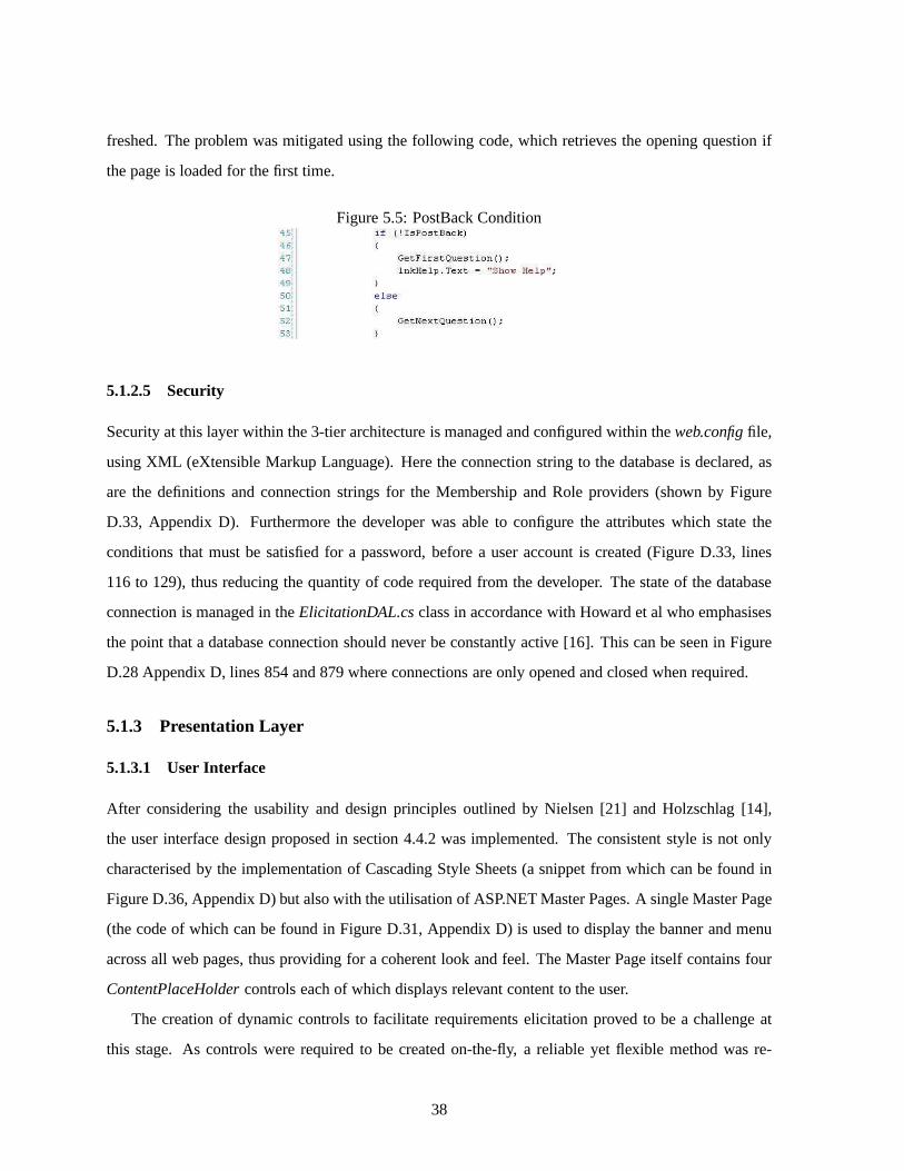
freshed. The problem was mitigated using the following code, which retrieves the opening question if
the page is loaded for the first time.
Figure 5.5: PostBack Condition
5.1.2.5 Security
Security at this layer within the 3-tier architecture is managed and configured within theweb.configfile,
using XML (eXtensible Markup Language). Here the connection string to the database is declared, as
are the definitions and connection strings for the Membership and Role providers (shown by Figure
D.33, Appendix D). Furthermore the developer was able to configure the attributes which state the
conditions that must be satisfied for a password, before a user account is created (Figure D.33, lines
116 to 129), thus reducing the quantity of code required fromthe developer. The state of the database
connection is managed in theElicitationDAL.csclass in accordance with Howard et al who emphasises
the point that a database connection should never be constantly active [16]. This can be seen in Figure
D.28 Appendix D, lines 854 and 879 where connections are onlyopened and closed when required.
5.1.3 Presentation Layer
5.1.3.1 User Interface
After considering the usability and design principles outlined by Nielsen [21] and Holzschlag [14],
the user interface design proposed in section 4.4.2 was implemented. The consistent style is not only
characterised by the implementation of Cascading Style Sheets (a snippet from which can be found in
Figure D.36, Appendix D) but also with the utilisation of ASP.NET Master Pages. A single Master Page
(the code of which can be found in Figure D.31, Appendix D) is used to display the banner and menu
across all web pages, thus providing for a coherent look and feel. The Master Page itself contains four
ContentPlaceHoldercontrols each of which displays relevant content to the user.
The creation of dynamic controls to facilitate requirements elicitation proved to be a challenge at
this stage. As controls were required to be created on-the-fly, a reliable yet flexible method was re-
38
quired in order for controls to be positioned correctly on the form. Experimentation took place using
dynamic Cascading Style Sheets but resulted in applicationlogic code being mixed with unstructured
presentational markup. At this stage, it was decided to use the ASP.NETTableobject, which contains
methods to append Cell, Row and Column objects to a table dynamically. A method calledCreateCom-
ponentTable()(see figure D.32, Appendix D) was implemented to build a dynamic table containing the
necessary controls. After a question is answered, the tabledisposes itself to remove any old controls
from the previous question and adds three new Row objects to the table, primed for the next question
and response. The top is used to contain the question, the second contains the dynamically generated
controls required for the answer and the third row holds the Submit and Exit buttons (also created
dynamically). Using the results passed back by theGetNextQuestionquery, the method invokes a par-
ticular function (an example of which can be found in Figure D.34 in Appendix D) to return a Cell
object containing the required control, (the control of which is created using the ’ControlCreator.cs’
class, see section 5.1.2.2). The process continues until all the necessary controls are added into the table
to facilitate requirements elicitation, therefore satisfying the second minimum requirement. In doing so,
event handlers are also added to the createdButtoncontrols. If an incorrect data type is entered for an
answer JavaScript is used to alert the user.
5.1.3.2 Navigation
The navigational structure outlined in section 4.4.3 was implemented using an ASP.NETweb.sitemap
file (Figure D.35, Appendix D). Within this file, the menu structure is defined within nodes, using XML.
The menu itself is laid horizontally, allowing for more roomon the page and hence more controls. As
the mouse cursor hovers over a root node, the node expands to display to all its child nodes. As the
mouse is moved away, it takes 500 milliseconds for the expanded node to disappear.
5.2 Second Iteration
At this stage in the project, all the minimum requirements aswell as the ’Must have’ and ’Should have’
use cases had been fulfilled. The second iteration saw the introduction of features that were regarded as
optional and hence were categorised as ’Could haves’ and ’Won’t haves’ in the MoSCoW prioritisation
technique (Figure B.1 Appendix B). However due to time constraints, only theDelete Project’Could
have’ use case was implemented, to allow an administrator todelete aProject.
39

Chapter 6
Testing
The following chapter addresses theTestingworkflow of the USDP and in doing so concludes the
work required to fulfil the USDP development process. The purpose ofTestingis to ensure that the
use cases outlined in Appendix B function correctly. As per the deployment model outlined in section
4.1, functional testing will take place via the internet, tosimulate how potential users access the web
application. Furthermore, in accordance with standard testing guidelines, the IEEE Std 829-1998 (IEEE
Standard for Software Test Documentation) paper [22] has been used as a basis for test planning.
6.1 Test Plan
By using the guidelines proposed by the IEEE Std 829-1998 [22], test plans have been devised in
Appendix E. Bennett et al [9] suggests that the use cases derived in theRequirements and Analysis
workflows should provide the basis for testing. Given this, the use cases defined in Figures B.4 and
B.5 in Appendix B, have been added to a table of test items (Figures E.1 to E.5). As can be seen each
test item is split into a series of sub-tests to ensure that elements of the application operate correctly
under different inputs and actions. The test plans themselves contain columns suggested by the IEEE
Std 829-1998 paper [22]. The first column uniquely identifiesthe test item and the second provides it
with a name. The third and fourth columns state the required inputs and outputs from the tests carried
40

out, with the fifth, sixth and seventh columns listing any actions that need fulfilling prior to the tests
being carried out. Finally, results are explained in the last column.
6.2 Summary of Test Results
All tests were carried out by the developer and client, with results noted and highlighted in red, as
indicated in Appendix E. Overall, tests carried out on the use cases were successful, mainly due to the
ongoing testing performed during the implementation. The proceeding sections provide more specific
testing details regarding the aim of the application:- to produce a requirements elicitation tool. Further
test items can be found in Appendix E.
6.2.1 Creating a Survey
TheAdd Questionuse case was tested here, results are found in Figure E.2, Test Item ID: U8. This test
item was expanded on by adding a set of ten questions (provided by the client and found in Appendix
B) into the database, via theAddQuestion.aspxpage. Findings are discussed in Figures E.6 to E.8.
From the results, the client found the same predecessor could be entered twice for one question, which
although has no impact on the algorithm, wastes space in the database. This flaw has been amended.
6.2.2 Elicitation Algorithm
In testing the elicitation algorithm, a set of ten questions(entered as part of the previous test) were
answered. In doing so, theSubmit Answeruse case was being tested (Figure E.3, Test Case ID: U10).
Various answers were provided over multiple Q&A Sessions todetermine whether predecessors were
being satisfied and hence the correct question was being displayed. As can be seen from the results in
Figures E.9 to E.11, the elicitation algorithm worked as desired even with adverse conditions. A minor
bug did arise in Test Case ID A3 (Figure E.9) regarding operational and technical questions with mixed
predecessors, which although has now been resolved does provide a basis for further research.
6.2.3 Reports Generation
The testing process for theGenerate Reportuse case involved the generation of a report for one of the
Q&A Sessionscompleted in the previous section (Test Case ID U12). As a further test, the report was
exported to a spreadsheet application installed locally, to satisfy theExportuse case (Test Case ID U14)
41

and to ensure there were no platform issues. As can be seen from the results in Figure E.4, the tests
performed were successful.
6.2.4 Security
In testing the security of the web site, valid and invalid user credentials were supplied (Figure E.1 Test
Case IDs U1 and U2). As noted in the results, the web site did not allow any unauthorised access. Test
Case ID U1 simulated an unsuccessful SQL injection attack, in an attempt to access the web site using
invalid login credentials. Test Case ID U3 found in Figure E.1 attempted to add a user with a weak
password which as the results indicate, was not accepted.
6.2.5 Web Browser Testing
To ensure the consistency of the web site was maintained, each page was tested in the three web browsers
outlined in section 4.4.2. Results showed that there was little difference across each browser. The layout
and positioning of text and controls was identical, characterised by the use of CSS and ASP.NET Master
Pages. Apart from small variations in font sizes and the styles applied to the controls, consistency was
largely maintained throughout. Furthermore, validation techniques through the use of JavaScript also
functioned correctly across the browsers.
6.3 User Acceptance Testing
Given that Nielsen points out that “designers are not users”[21], it was necessary for the client and other
random individuals to be invited to test the application to ensure that all initial requirements captured in
Chapter 3 were met, as were the usability considerations. Toprovide structure, a test plan was devised
with a set of tasks the users had to complete alongside the developer, who noted any feedback. From
a usability perspective, the users were able to navigate andinteract with the system well, with little
prompting required from the developer. In terms of functionality, the client made recommendations
which have now been implemented. A set of findings are presented in Figures E.12 to E.16.
42
Chapter 7
Evaluation
In evaluating the project, the initial objectives and requirements are discussed and the user interface
and navigational aspects are subjected to the Nielsen Usability Heuristics. Furthermore, the developed
application is evaluated against the clients current solution with tests carried out on the algorithm to
determine its success. Finally the limitations are discussed and possible enhancements are suggested for
future developments.
7.1 Schedule
The project schedule (found in Appendix G) was largely followed but alterations occurred due to the
work required from other University modules. Most significantly, by late January the project was de-
layed as a result of the examination period which as a consequence meant later completion dates for
the stages followingSystem Design. This decision was taken to allow the project to return to schedule
through the use of attainable dates which, as a result, didnot compromise the projects delivery. The
project schedule was structured largely around the USDP. TheRequirements Capturestage followed by
theRequirements Analysisstage allowed for a deeper understanding of the problem through a meeting
with the client and further research. Both phases proved successful in not only capturing the issues
specific to the client but also in understanding the general problem of selecting questions from a set of
43

satisfied pre-conditions. TheSystem Designstage stepped through a series of design iterations resulting
in the final elicitation algorithm. In developing the algorithm in such an incremental fashion, it led to
the most appropriate and efficient solution to come to light.A further meeting was arranged with the
client to sign-off the system design before progressing to the next phase. During theImplementation
stage issues surrounding the development of the algorithm and the use of dynamic controls were appar-
ent. However, these were resolved and the stage was completed ahead of schedule, allowing forTesting
to start earlier. The feedback gained through client testing was positive with further recommendations
made and implemented. On a whole, the initial structure of the project plan was followed but as a result
of changing circumstances the schedule had to adapt in ordersatisfy the workload required.
7.2 Meeting Objectives
As a method of evaluating the project, this section outlineshow the original objectives outlined in
Chapter 1 have been fulfilled.
• Analyse the current system in place for data migration within CSC.: Fulfilled. Research into
current business practices and the requirements elicitation system was carried out in Chapter 3
through an extensive requirements specification with the aid of UML (found in Appendix B).
• Decide upon the system architecture (standalone or web based) based upon clients requirements.:
Fulfilled. Chapter 3 addresses the issue of the application architecture based upon the clients
requirements and in conjunction with Chapter 4 the proposalfor a web based system was put
forward.
• Research similar systems in place, methodologies and technologies that can be used for devel-
oping the system.: Fulfilled. Current applications such as the Bristol OnlineSurvey [2] and Sur-
veyMonkey [5] have been critically analysed, as have proposed techniques put forward by Belani
et al [8], in Chapter 3. Research into software development methodologies as well the available
technologies have been discussed in Chapter 2.
• Produce a design for the system.: Fulfilled. A design for the proposed solution has been outlined
in Chapter 4.
• Build the system using the chosen technology to meet the minimum requirements.: Fulfilled. The
44

Unified Software Development Methodology (USDP) has been used accordingly throughout the
development of the solution as illustrated by the project schedule and structure of the report.
• Test the system with suitable test data to highlight any problems.: Fulfilled. Chapter 6 makes ref-
erence to a set of test plans found in Appendix E to standardise the testing phase, using questions
provided by the client.
• Evaluate the solution based upon the clients requirements.: Fulfilled. The current chapter ad-
dresses this objective.
7.3 Meeting Requirements
The minimum requirements listed in Chapter 1 have all been delivered (and exceeded) as indicated
below. Furthermore, as part of the USDP methodology and in conjunction with the MoSCoW task
prioritisation technique further requirements captured in Chapter 3 have been implemented.
• Implementation of a database suitable for storing questionsets, requirements information and
user details.: Delivered. A database was designed and implemented to facilitate requirements
elicitation with the ability to store questions, users answers and user login details securely.
• Functionality for generating dynamic web forms for requirements elicitation.: Delivered. Func-
tionality to allow the generation of dynamic form controls for requirements elicitation was imple-
mented as part of the application logic layer using ASP.NET and C#.
• Functionality for generating reports based on the requirements information that has been gath-
ered using the system.: Delivered. Reports displaying users questions and answers provided for a
Q&A Session, for which requirements elicitation data is gathered can begenerated and exported
by either a limited application user or an administrator.
7.4 Usability
During the design of the user interface, the Nielsen Usability Heuristics were considered to ensure that
the interface conformed to standard guidelines. To evaluate the interface and navigational components,
the web application was subjected to these heuristics by selecting ten users at random, to perform certain
45

tasks on the system (found in Figures E.12 to E.16). The taskswere simple yet designed to mirror the
day-to-day usage of the application. Upon completion, users were asked questions in relation to how
the web application satisfied the relevant Nielsen Usability Heuristics. Furthermore, users were asked
to comment on the use of predecessors over successors and whether one method was more intuitive than
the other.
7.4.1 Nielsen Usability Heuristics
This section aims to summarise the Nielsen usability feedback (noted in figures F.1 to F.3, Appendix
E) obtained from user testing. Largely users were satisfied with general usability of the application as
indicated in the results. The majority of test users believed the systems dialogue was understandable
and was conveyed in a manner that users could understand. However, there were exceptions to this,
characterised by users 2, 3, 7 and 10 who believed that the error messages were not explained well
enough or were too technical, possibly due to the fact that the system is specific to a particular domain.
A further Nielsen heuristic is that of reducing memory load required of the user, which was agreed
upon by the majority. However this was offset by users 3, 7 and10 who commented on the fact that
when creating a survey, lots of information such as pre-conditions and options had to be remembered in
order to define conditions. This is an important issue which could provide a basis for further research
by developing a user interface facilitating the creation ofa survey but at the same time minimising the
memory load required of a user. All users agreed that the interface was consistent, characterised by
the use of colour, layout and style. The use of error messageswere also commented upon with many
users agreeing that messages were appropriate and used in the correct places. Finally, positive feedback
was obtained for the help functionality, with most users being able to locate the help link correctly,
during aQ&A Session. However users 6 and 10 believed the application would benefit from help being
available during the creation of a survey via theAdd a Questionpage. In doing so, this may indeed
counter the issues associated with memory load. In conclusion, the Nielsen Usability Heuristics were
largely satisfied. Although some feedback was negative, it provides a good starting point for further
development and research in producing an efficient yet user friendly environment for creating surveys.
7.4.2 Navigation
In order to evaluate the navigational menu found on the web site, figure F.4 in Appendix F shows a table
indicating the number of mouse clicks required of the user tonavigate from one page to another. As can
46

be seen, the minimum number of clicks required is 1 due to the links found within the static menu. The
maximum number of clicks is 3 but such cases only arise when the user has logged out. The number
of clicks required in order to navigate to theMyReports.aspxpage is dependent upon on the number
of questions asked to the user. Furthermore, the number of clicks required suggests that the overall
navigational time is low, a point raised in section 4.4.3 andnoted by the developer during user testing.
Lastly, the menu takes up little space on the screen but is immediately identifiable as a navigational
instrument, justified from the results obtained through testing, where no users had navigational issues.
7.5 Client Evaluation
The client evaluated the system by performing a set of tasks found in Figures E.12 to E.16. The outcome
of the tasks were noted and feedback was obtained. On a whole the client was “very happy” [13] with
what was achieved. From the tests carried out, few difficulties were encountered with usability issues
noted. The ’User Administration’ tasks were completed successfully as were the ’Project Administra-
tion’ tasks. However during the creation of a survey, the client and other users suggested the use of
Answer Optiontemplates for commonly required options to reduce the amount of user input, which
as a result may counter some of the usability points raised insection 7.4.1. Whilst adding questions
into the system, the client forgot to specify aQuestion Typeon several occasions which suggests that
this functionality be repositioned on the form. Again this may be a consequence of the amount a user
has to remember when creating a survey. Finally, when asked the question regarding the intuitiveness
of successors over predecessors, the client stated that “the general maintainability of the application is
more important than intuitiveness and the most technicallyefficient should not be compromised” [13].
This is indeed an interesting response, suggesting that theuse of predecessors over successors makes
little difference.
7.6 Comparison with the Clients Existing Solution
In evaluating the solution, it seems appropriate to compareit to the clients existing solution, noted
in section 3.2.1. Currently, requirements elicitation is inflexible, taking place via a set of hard-coded
questions and precursors and thus making configuration (such as the addition of questions) difficult.
Furthermore, in comparison to the Bristol Online Survey [2]and SurveyMonkey [5] systems discussed
in section 3.3.1, which are although not used by the clients organisation, do not allow for the use of
47

pre-conditions when adding questions and creating surveys. In comparison with the existing system, the
new application has far more configurable properties, such as being able to add questions, predecessors,
answer options and projects, with the ability to store usersanswers and generate reports. The applica-
tion itself is web based thereby allowing authorised users to perform requirements elicitation with no
geographical boundaries and as a consequence, security measures have been implemented. Furthermore
no controls required for theQ&A Sessionare created manually as they are all generated on the form
dynamically, thus cutting down the time required to build a survey. All these capabilities contrast with
the current standalone system whereby questions, predecessors, answer options and form controls are
added programmatically with no configuration ability and regards to security. Users answers are also
not maintained in the clients current system.
In evaluating the solution it was suggested by Shakhlevich &Bennett [25] that a question be added
to the new and existing solutions to ascertain the time takento perform such an action in both systems.
As such a single question (with a pre-condition and the answer options, ‘Yes’ and ‘No’) was added
into the two applications to observe the required effort andtime to perform such a task. The results for
adding a question in the developed solution were positive, taking just over 2 minutes from accessing the
relevant web page to submitting the new question. Adding thesame question in the existing solution
took substantially longer as the form controls (DropDownList, Labels and Buttons) had to be created
manually and then the program methods had to be written to handle events on the controls, taking
approximately 14 minutes. Further time was taken to test that the methods worked correctly. The
developed solution is therefore not only more configurable but also far more scalable than the existing
solution as the number of questions increase.
7.7 Limitations
The initial design of the elicitation algorithm involved the use of disjunctive and conjunctive pre-
conditions, in which a question could have the predecessor:
(Q1= 1 ∨ Q2= ‘Yes’)∧ (Q3> 0)
Although such a condition did not form part of the initial requirements it was considered more
flexible and beneficial if implemented, since it allowed conjunctive and disjunctive predecessors to be
assessed. The difficulty encountered when implementing such functionality occurred when the algo-
rithm attempted to find the questions with predecessors (similar to above) that had been satisfied, which
48

the developer believes is a consequence of the database schema and would require a minor revision to
allow for disjunctive pre-conditions. Furthermore in conjunction with time constraints on the project,
only disjunctive predecessors were therefore implemented.
A further limitation of the solution is thatRadioButtoncontrols were not implemented for boolean
answers and as suchDropDownListcontrols were used instead. Whilst it is acceptable forDropDown-
Lists to be used for boolean answers, it seems more appropriate forRadioButtonsto be utilised given
their common relation to binary selections.RadioButtonswere not implemented due to the nature in
which event handlers were applied to dynamically createdRadioButtoncontrols and the difficulties en-
countered. Whilst the issue may be possible to overcome, thetime spent trying to resolve it prevented
further development and as such was abandoned.
7.8 Possible Enhancements
In order to enhance the systems current functionality the points raised in section 7.7 could be considered.
As mentioned, difficulties were encountered when implementing the algorithm to consider conjunctive
predecessors. Such functionality could be achieved with the addition of a table in the current database
schema to store conjunctive and disjunctive predecessors for a question as a single record by relating
predecessors within the ELICITATIONPREDECESSOR table. However the main challenge is writ-
ing the algorithm (in SQL) to find and update pre-conditions containing disjunctive and conjunctive
relations. After this point the process of displaying the correct question is trivial.
The purpose of theQuestionOrderfield found within the ELICITATIONQUESTION table (dis-
cussed in section 4.3.2) was to facilitate the re-ordering of questions independently of unique identifiers.
Yet due to time constraints such functionality was not implemented but could be achieved via aListBox
control containing an ordered list of questions, along withtwo Buttonsto move the selected questions
up and down in the list. Whilst moving the question down the list would be unrestrictive, moving a
question up the list (resulting in a lower question number) would require checks to ensure that the ques-
tions precursor is not compromised (i.e. the pre-conditionfor questiona does not refer to questionb
which comes aftera).
In terms of the applications usability aButtonto allow users to step back through theQ&A Session
could be added and therefore allow users to change a previousanswer. Caution however must be taken at
this stage as stepping back through aQ&A Sessionhas the potential for changing satisfied predecessors
49

and hence which questions are successively displayed. Although there will be little impact on the
presentation layer since the controls are created dynamically, appropriate steps would be required to
ensure correct pre-conditions are marked and unmarked as satisfied.
As a final enhancement, functionality could be placed withinthe system to allow questions and pre-
conditions to be displayed as a tree structure, mapping all possible routes. In doing so it would allow the
application administrators to find the most common routes taken by users during aQ&A Session. It may
also act as a key maintenance tool and provide evidence for revising the entire question set, if the tree
indicates that the current questions are not effective in achieving requirements information. Furthermore
the tree may also act as an integrity checker, by highlighting any loops that may occur when users are
answering questions.
7.9 Conclusion
The premise for the project was to produce a requirements elicitation tool to aid the Child Health data
migration process within the Computer Sciences Corporation (CSC). However, at the same it was im-
portant to build a generic application by using the CSC problem domain as a platform for developing
such a tool.
The main achievement of the project is that a configurable webapplication has been designed and
implemented to allow the creation of dynamic web surveys through the use of pre-conditions. Further-
more, users are able to provide answers to questions which may then go on to determine which further
questions are displayed, thus eradicating the risk of beingasked irrelevant questions. Such functionality
is achieved through the use of dynamic controls, which are created on the web page in run time and allow
the users to input an answer. In addition to this, the web application can be applied to almost any field of
endeavour, characterised by the generic design of the elicitation algorithm, which itself saw several iter-
ations. Feedback obtained from the client and other users was positive with all minimum requirements
and objectives fulfilled (and exceeded in some cases), evident from the testing and evaluation results.
The implementation of a widely used development process andthe utilisation of various technologies
are also achievements in themselves, since the learning of new methods and concepts resulted in a fully
functional and successfully deployed web application thatwas delivered on time.
50

Bibliography
[1] About postgresql.http://www.postgresql.org/about/Last Accessed [15th November
2007].
[2] Bristol online surveys.http://www.survey.bris.ac.uk/ Last Accessed [3rd December
2007].
[3] Cascading style sheets level 2 revision 1 (css 2.1) specification.
http://www.w3.org/TR/CSS21/ Last Accessed [13th November 2007].
[4] Microsoft technet: Sql server overview.
http://technet.microsoft.com/en-gb/library/ms166352.aspx?wt.slv=RightRail
Last Accessed [3rd December 2007].
[5] Surveymonkey.http://www.surveymonkey.com/ Last Accessed [3rd December 2007].
[6] XHTML 1.0 The Extensible HyperText Markup Language (SecondEdition).
http://www.w3.org/TR/xhtml1/ Last Accessed [13th November 2007].
[7] D. Avison and G. Fitzgerald.Information Systems Development Methodologies, Techniques and
Tools (Third Edition). McGraw-Hill, 2003.
[8] H. Belani, K. Pripuzic, and K. Kobas.Implementing web-surveys for software requirements elici-
tation. pages 465–469, June 15–17 2005. Telecommunications, 2005. ConTEL 2005. Proceedings
of the 8th International Conference on Volume 2.
[9] S. Bennett, S. McRobb, and R. Farmer.Object-Oriented Systems Analysis And Design Using UML
(Second Edition). McGraw-Hill, 2002.
51

[10] S. Bennett, S. McRobb, and R. Farmer.Object-Oriented Systems Analysis and Design Using UML
(Third Edition). McGraw-Hill, 2005.
[11] P. Bocij, D. Chaffey, A. Greasley, and S. Hickie.Business Information Systems Technology, De-
velopment and Management for the e-business (Second Edition). Financial Times/Prentice Hall,
2003.
[12] R. Elmasri and S.B. Navathe.Fundamentals of Database Systems (Fourth Edition). Pearson
Education, 2004.
[13] W-T. Gaskill. Client Meeting.
[14] M. E. Holzschlag.Web by Design The Complete Guide. Sybex, 1998.
[15] R. Hoque.Practical JavaScript Programming. pages 3–10. M&T Books, 1997.
[16] M. Howard and D. LeBlanc.Writing Secure Code (Second Edition). pages 397–411. Microsoft
Press, 2003.
[17] I. Jacobson, G. Booch, and J. Rumbaugh.The Unified Software Development Process. Addison-
Wesley, 1999.
[18] A. Levitin. Introduction to The Design & Analysis of Algorithms. pages 43–50. Addison Wesley,
2003.
[19] J. Liberty and D. Hurwitz.Programming ASP.NET (Third Edition). O’Reilly Media, 2005.
[20] J. C. Meloni.PHP Fast and Easy Web Development (Second Edition). Premier Press, 2002.
[21] J. Nielson.Usability Engineering. Academic Press, 1993.
[22] Institute of Electrical and Electronics Engineers (IEEE). IEEE Standard for Software Test Docu-
mentation. Technical Report IEEE Std 829-1998, 1998.
[23] B. Schneiderman and C. Plaisant.Design the User Interface (Fourth Edition) Strategies For Effec-
tive Human-Computer Interaction. Pearson Education, 2005.
[24] R. W. Sebesta.Programming the World Wide Web (Third Edition). Pearson Education, 2006.
[25] N. Shakhlevich and B. Bennett.Final Year Project Progress Meeting.
52

[26] S. Skidmore and M. Eva.Introducing Systems Development. Palgrave MacMillan, 2004.
53
Appendix A
Personal Reflection
The opportunity for the development of this project came about whilst working for the Computer Sci-
ences Corporation (CSC) during my work placement year. Towards the start of the third academic year,
I was keen to work on a project that had potential to make a difference and I therefore feel honoured
to have been able to work with an old colleague and my client Dr. William Thirsk–Gaskill of CSC in
producing a requirements elicitation tool.
Initially, I had different ideas about how I was going to attempt to solve the problem and when a
new idea for the algorithm was proposed, I had difficulties inunderstanding how it would actually work.
However, as I began to develop it further and with the help provided by Brandon it became easier. Upon
reflecting on this stage in the project, I believe that I became so engaged with my initial ideas that I
forgot about the bigger picture and trying to understand someone elses approach became much harder,
until I sought advice enabling me to understand the problem.My advice to other students in similar
predicaments is to take time out and return to the problem later, I did this during the project and it
certainly helped. Furthermore, don’t be afraid to ask for advice from supervisors or accessors, I found
that discussing issues with them allowed me to focus and concentrate on the issues which mattered.
When selecting a project at the start of the year, my advice toother students is to select one that
interests you and that perhaps you might enjoy. Don’t be afraid of a challenge, certainly pick a project
that you are able to attain but at the same time don’t be put offby any pre-conceptions you may have. If
you have been given the opportunity to develop a solution fora third party, think about how you could
54

evaluate it as this forms an important of the project.
During the initial stages of the project, ensure that you define realistic minimum requirements as
over complicating the project can lead to a limited solutionor late delivery.
With regards to the project schedule I found myself working more on the project in the last semester
than in the first, therefore my advice is to do as much work as possible before the Christmas break as
by the time January comes revision takes over and project work does not resume until late January,
thus demonstrating the importance of time management. In scheduling the work make sure you plan
it out early, and base your project plan around the chosen methodology as it is then easier to plan the
workload and structure the final report. Furthermore donot underestimate the workload especially the
time taken for implementing the solution (it really does take time and careful thought), start coding as
soon as possible. If you are using a new technology/languageensure that enough time is spent getting
to grips with it, avoid learning the language and implementing a solution at the same time as the final
product may be limited. When writing up the project, ensure that you have at least a month to do so as
planning and writing takes longer than you think. Most importantly, backup your work throughout and
keep old copies, then if work gets lost or corrupted it can be restored (remember if lost, 8 months worth
of work is gone!).
When dealing with third parties ensure that a professional conduct is maintained throughout (remem-
ber you are representing the University and all your peers).Ensure that when meetings are arranged,
you are aware of the meeting place and arrive on time. Remember the client is taking time out of their
schedule to meet you and if you are late, the meeting will overrun. Before the meeting, make sure you
are prepared. My advice is to draft out a set of questions/points you would like to address during the
meeting and then cross them off as they are discussed. Also during the process, don’t be afraid to cast
your own points or concerns. Furthermore, make notes on whatthe client says in the meeting, as these
will form the requirements of the project. Don’t however pre–empt the client by telling them what they
want, instead use your knowledge to convey how such requirements could be achieved.
Finally, the project should be about learning and producinga quality piece of work, so have fun at
the same time.
55

Appendix B
Requirements Capture and Analysis
Figure B.1: UML Implementation Diagram
56
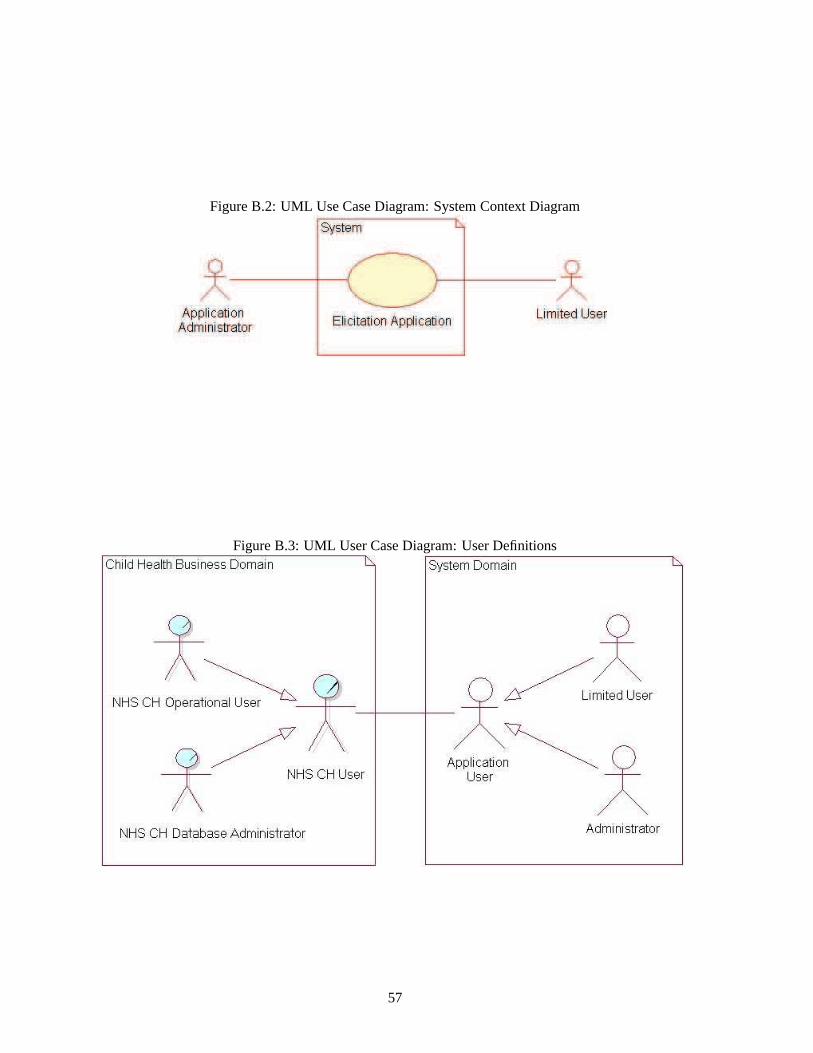
Figure B.2: UML Use Case Diagram: System Context Diagram
Figure B.3: UML User Case Diagram: User Definitions
57

Figure B.4: UML User Case Diagram: Application Administrator
58

Figure B.5: UML User Case Diagram: Limited User
59

Figure B.6: UML Activity Diagram: Add a Question
60
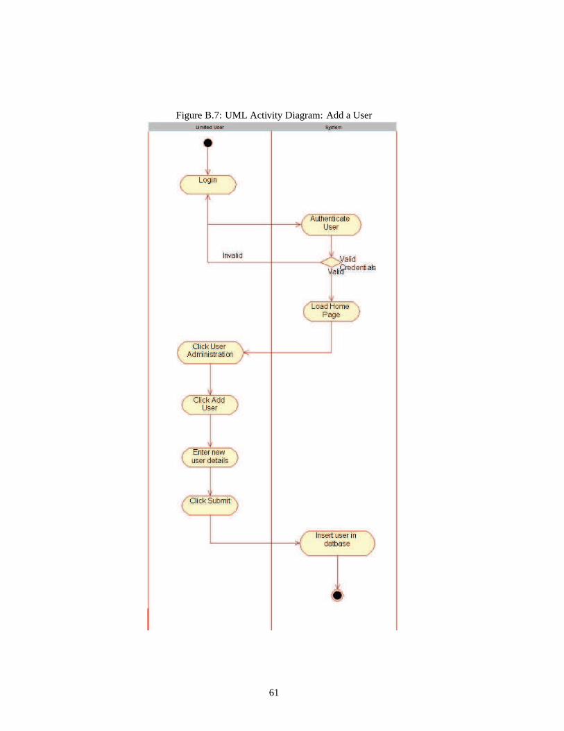
Figure B.7: UML Activity Diagram: Add a User
61

Table B.1: MoSCoW Prioritisation
Priority Use Case
Must Haves Add User
Delete User
Change a Password
Add Question
Submit Answer
Generate Report
Login
Logout
Create Q&A Session
Should Haves Export Report
Add Project
Get Help
Could Haves Modify Question
Delete Question
Won’t Haves Delete Q&A Session
62

Figure B.8: Questions provided by the Client (Page 1)
1.) How many sets of schedules does your Child Health system currently run?
CH User Type:Operational
Exp Data Type:Integer
Predecessor:N/A
2.) Are all these run from the same site?
CH User Type:Operational
Exp Data Type:Boolean
Predecessor:Q1> 1
3.) Does each office or site see exactly the same view of the Child Health system (same software,
same data)?
CH User Type:Technical
Exp Data Type:Boolean
Predecessor:Q2= ‘No’
4.) Does your current Child Health system contain ANY patient records from any other care settings
(e.g. Community, Mental Health, acute care)?
CH User Type:Operational
Exp Data Type:Boolean
Predecessor:(Q1= 0)∨ (Q2= ‘Yes’) ∨ (Q3= ‘No’) ∨ (Q3= ‘Yes’)
5.) Please list all the other care settings which have records inthe same system as Child Health.
CH User Type:Operational
Exp Data Type:String
Predecessor:Q4= ‘Yes’
63

Figure B.9: Questions provided by the Client (Page 2)
6.) Please describe in as much detail as possible how you tell a Child Health record from those
belonging to each of the other care settings.
CH User Type:Operational
Exp Data Type:String
Predecessor:(Q4= ‘No’) ∨ (Q5= ‘’) ∨ (Q5 ! = ‘’)
7.) Please enter the age at which a living patient ceases to be under the care of the Child Health unit.
CH User Type:Operational
Exp Data Type:Integer
Predecessor:(Q6= ‘’) ∨ (Q6 ! = ‘’)
8.) Does this age also apply to patients with special needs?
CH User Type:Operational
Exp Data Type:Boolean
Predecessor:Q7 ! = ‘’
9.) What is the age for patients with special needs?
CH User Type:Operational
Exp Data Type:Integer
Predecessor:Q8= ‘No’
10.) Please enter the registration status which indicates a birth which is transferred out.
CH User Type:Operational
Exp Data Type:String
Predecessor:(Q9<= 0)∨ (Q8= ‘Yes’)
11.) Please enter the registration status which indicates a patient who has moved out.
CH User Type:Operational
Exp Data Type:String
Predecessor:(Q10= ‘’) ∨ (Q10 != ‘’)
64

Figure B.10: Questions provided by the Client (Page 3)
12.) Of all the deceased patients in the current system, do you require any to be EXcluded from
SystmOne?
CH User Type:Operational
Exp Data Type:Boolean
Predecessor:(Q11= ‘’) ∨ (Q11 != ‘’)
13.) Is your current system provided by a vendor or in-house?
CH User Type:Technical
Exp Data Type:Boolean
Predecessor:N/A
14.) What is the name of the vendor?
CH User Type:Technical
Exp Data Type:String
Predecessor:Q13= ‘Vendor’
65

Figure B.11: Project Terminology Definitions used in Chapter 3
Application – Refers to the computer program under development (i.e. theproject deliverable)
Limited Application User– Refers to an individual who uses the application being developed for this
project.
Application Administrator– Refers to an individual who may or may not use the application but has
overall control of the system and acts as the governing individual.
NPfIT – National Programme for IT (when read aloud it sounds like “enn–pee–fit”. Current project
undertaken where by the UK government contract various private-sector companies, to work together
along with the NHS to upgrade the current NHS IT infrastructure.
NHS Trust– An NHS Trust is an organization which provides healthcare services to a designated area,
e.g. North Lincolnshire PCT.
CH Project– Child Health Project. This is a term used by CSC as a unique reference to the deployment
of the Child Health system to an NHS Trust. E.g. Northeast Lincolnshire.
NHS CH Users– Users who work for the National Health Service and use the Child Health System.
There are two types of users who use the Child Health system
1. NHS CH Technical User – deal with the technical/DBA side ofChild Health.
2. NHS CH Operational User – Use the Child Health system as part of their job.
CH system– Child Health System.
Q&A Session– Is a time over which an application user uses the system and provides answers to
questions. The end of the session is signalled when the user answers the very last question and a report
is produced, detailing which questions were asked along with the answers. A Q&A session may occur
more than once for a CH Project (described above).
CH– Stands for Child Health. The module is part of a software suite called “SystmOne” which serves a
number of care settings including GP, Community and Hospice, as well as Child Health.
Legacy CH System– An existing Child Health system currently being used by an NHS Trust.
66

Figure B.12: Requirements Capture meeting with client 29/10/2007 (Page 1)
Notes from meeting
The purpose of this document is to provide the reader with an overview of the discussions during the
first meeting between myself and the client. Throughout the meeting my client and I discussed what
would be required of the proposed system. Due to working withthe client during my work placement
year, I am currently aware of the fundamentals of what is required of the proposed system and thus
during the meeting we were able to concentrate in more specific areas. In the meeting I introduced
my client to the MuSCoW system of modelling requirements. This enabled us to break down the
project and prioritise certain tasks. My made clear the following functionality which should be apparent:
Must Haves... GENERAL: Database of questions/answers, user roles, user interface, output (in
the form of a report) and a list of un-answered questions. SPECIFIC: Ability to add a user, delete and
change passwords – use of Login credentials. Create Q&A Sessions and answer questions. Ability for
administrators to add questions. Users should be able to generate reports for a project.
Should Haves... GENERAL: None SPECIFIC: Adding projects into the database,for surveys to
be carried out against. Help functionality. Export
Could Haves... GENERAL: None SPECIFIC: Ability to change a question, though isnt of ut-
most importance in this iteration. Would be nice though... Should be able to delete projects.
Won’t Haves...GENERAL: None SPECIFIC: None
Discussion surrounding the users... In terms of the users who will be using the system, the
client made it clear that there will be two users of the application. A user and administrator. Each of
which will have different rights with regards to the system
67

Figure B.13: Requirements Capture meeting with client 29/10/2007 (Page 2)
User:
• Will have the ability to log in to the system and start the question answering process.
• May view and print out the final report.
Administrator:
• Will be able to add and remove users from the application.
• Will be able to define a user role (see the next page), which will ultimately determine which
questions they answer.
• Should have the ability to add or remove questions.
• Change the question ordering... not crucial at this stage.
With respect to the system, client emphasised importance ofdrawing a distinction between the types
of users referred to throughout the duration of the project and in order to make this clear I will now
provide descriptions for the types of users. Essentially, there will be users of the application (the
proposed system) and users whose field of endeavour we are attempting to get information about. The
user of the application can be defined as a normal user and an administrator. This user will then go on
to answer questions for their field of endeavour. Clarified below.
Users of the application being developed (the Project)
• Users
• Administrators
Users whose field of endeavour we are attempting to gather information about
• Database Administrators
• Operational Managers
68

Figure B.14: Requirements Capture meeting with client 29/10/2007 (Page 3)
The points above therefore provides us with the types of users who will be using the application (top) and
the users professions whom we are gathering information regarding their field of endeavour (bottom).
This will then go on to determine which questions the user answers. If they are database administrators,
they will answer technical issues. If they are operation managers, they will answer questions relating
to the general day-to-day running of the system. However, ifthe user is a database administrator and
operational manager then they will go onto answer questionsregarding both topics. These types of
user will be added into the database and will also be recordedagainst the questions, to identify the
type of question (technical or non-technical). Security measures were discussed and it was agreed that
usernames and passwords will be implemented to ensure that no unauthorised users can access the
system.
69
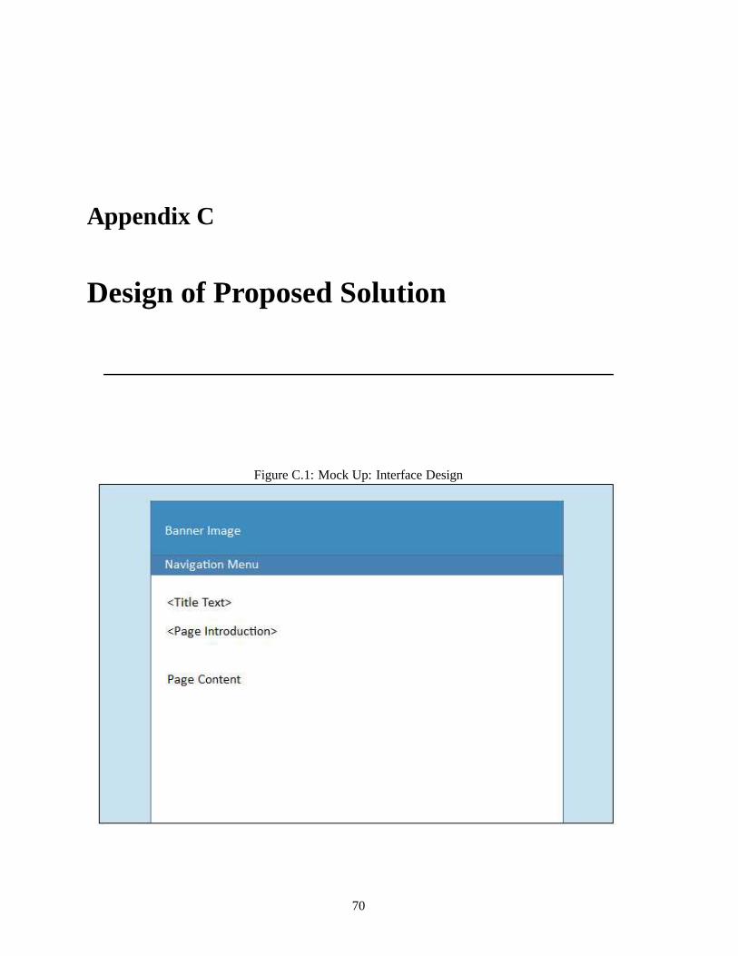
Appendix C
Design of Proposed Solution
Figure C.1: Mock Up: Interface Design
70
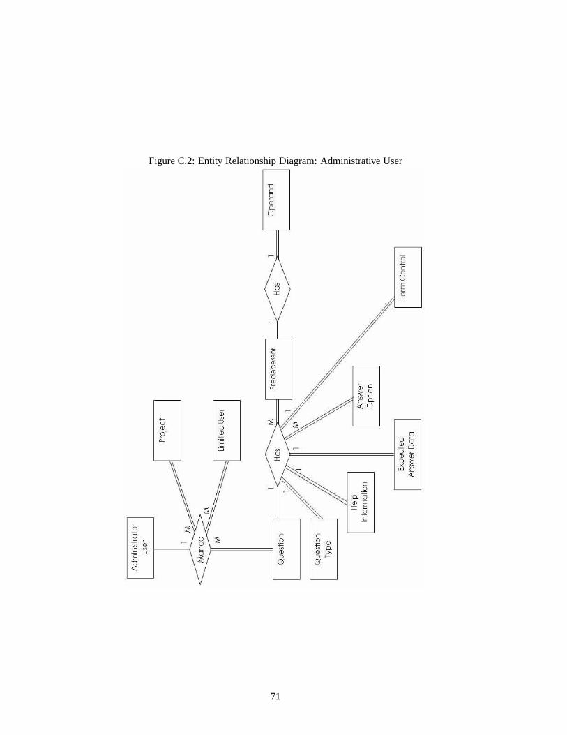
Figure C.2: Entity Relationship Diagram: Administrative User
71

Figure C.3: Entity Relationship Diagram: Limited User
72

Appendix D
Implementation
Figure D.1: Screenshot: Login (Default.aspx)
73
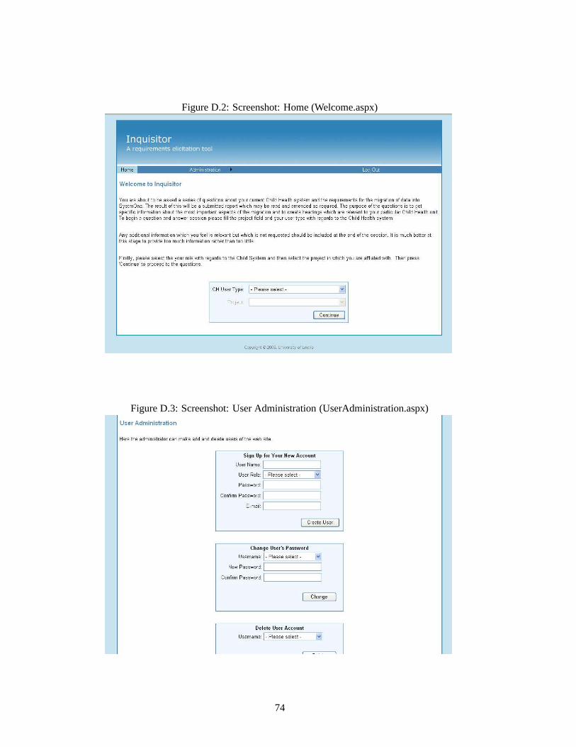
Figure D.2: Screenshot: Home (Welcome.aspx)
Figure D.3: Screenshot: User Administration (UserAdministration.aspx)
74

Figure D.4: Screenshot: Add a Project (AddProject.aspx)
Figure D.5: Screenshot: Delete a Project (DeleteProject.aspx)
75

Figure D.6: Screenshot: Add a Question (Part 1) (AddQuestion.aspx)
Figure D.7: Screenshot: Add a Question (Part 2) (AddQuestion.aspx)
76

Figure D.8: Screenshot: Question and Answer Session in Progress (QuestionAnswerSession.aspx)
Figure D.9: Screenshot: Question and Answer Session completed (QuestionAnswerSession.aspx)
77

Figure D.10: Screenshot: My Report (MyReport.aspx)
Figure D.11: Screenshot: Reports (before being run) (Reports.aspx)
78

Figure D.12: Screenshot: Reports (after being run) (Reports.aspx)
Figure D.13: Screenshot: Export Report (Reports.aspx)
79

Figure D.14: Screenshot: Log Out (withRemember Me(LoggedOut.aspx)
Figure D.15: Screenshot: Log Out (withoutRemember Me(LoggedOut.aspx)
80

Figure D.16: Screenshot: Questions with Pre-Conditions (QuestionsWithPreConditions.aspx)
81

Figure D.17: Stored Procedure: CreateSession
82

Figure D.18: Stored Procedure: GetFirstQuestion
83

Figure D.19: Stored Procedure: GetNextQuestion
84

Figure D.20: Stored Procedure: InsertAnswer (Page 1)
85

Figure D.21: Stored Procedure: InsertAnswer (Page 2)
86

Figure D.22: Stored Procedure: InsertAnswer (Page 3)
Figure D.23: Stored Procedure: GetAnswersForReportQuery
87

Figure D.24: Code: Insert New Question (ElicitationDAL.cs)
88

Figure D.25: Code: Insert New Predecessor (ElicitationDAL.cs)
89

Figure D.26: Code: Insert New Answer Option (ElicitationDAL.cs)
90

Figure D.27: Code: Create Session (ElicitationDAL.cs)
91

Figure D.28: Code: Get First Question (ElicitationDAL.cs)
92
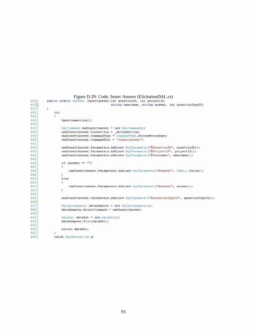
Figure D.29: Code: Insert Answer (ElicitationDAL.cs)
93
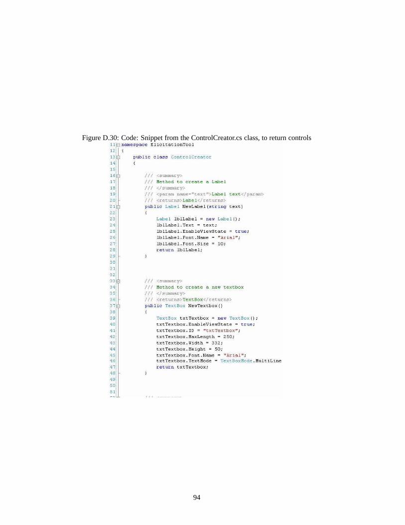
Figure D.30: Code: Snippet from the ControlCreator.cs class, to return controls
94

Figure D.31: Code: MasterPage.Master file
95

Figure D.32: Code: Snippet from the CreateComponentTable.cs class
96

Figure D.33: Code: Snippet from the Web.Config file
97

Figure D.34: Code: Method to return a cell containing a TextBox control
98

Figure D.35: Code: Snippet from the Web.Sitemap file, showing the hierarchical structure of the menu
99
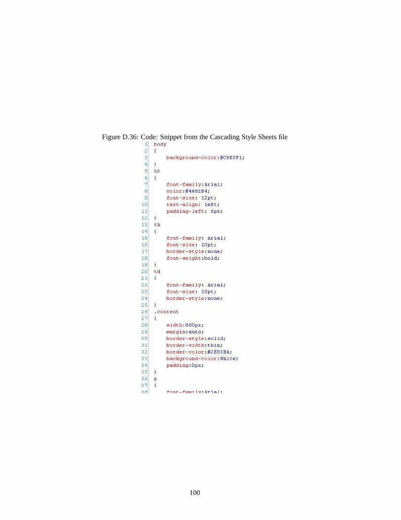
Figure D.36: Code: Snippet from the Cascading Style Sheets file
100

Figure D.37: Microsoft SQL Server 2005R©database diagram, showing the tables
101

Figure D.38: Microsoft Visual Studio 2005R©class diagram, showing the classes implemented
102
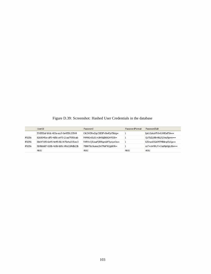
Figure D.39: Screenshot: Hashed User Credentials in the database
103

Appendix E
Testing
The test plan can be found on the following pages.
104

Figure E.1: Use Case Test Plan, using the headings proposed by IEEE [22] (Page 1)
105

Figure E.2: Use Case Test Plan, using the headings proposed by IEEE [22] (Page 2)
106

Figure E.3: Use Case Test Plan, using the headings proposed by IEEE [22](Page 3)
107

Figure E.4: Use Case Test Plan, using the headings proposed by IEEE [22] (Page 4)
108

Figure E.5: Use Case Test Plan, using the headings proposed by IEEE [22] (Page 5)
109

Figure E.6: Add Question Test Plan, using the headings proposed by IEEE [22] (Page 6)
110

Figure E.7: Add Question Test Plan, using the headings proposed by IEEE [22] (Page 7)
111
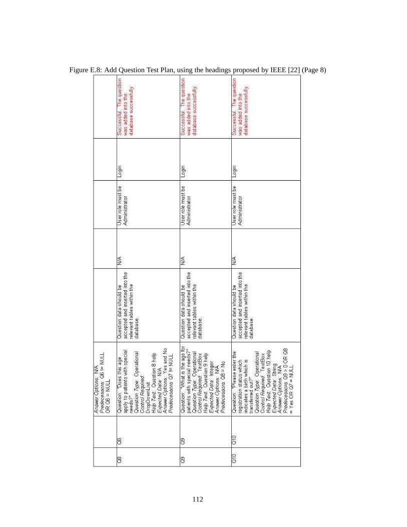
Figure E.8: Add Question Test Plan, using the headings proposed by IEEE [22] (Page 8)
112

Figure E.9: Answer Question Test Plan, using the headings proposed by IEEE [22] (Page 9)
113

Figure E.10: Answer Question Test Plan, using the headings proposed by IEEE [22] (Page 10)
114

Figure E.11: Answer Question Test Plan, using the headings proposed by IEEE [22] (Page 11)
115

Figure E.12: User Acceptance Test Plan (Page 1)
116

Figure E.13: User Acceptance Test Plan (Page 2)
117

Figure E.14: User Acceptance Test Plan (Page 3)
118

Figure E.15: User Acceptance Test Plan (Page 4)
119

Figure E.16: User Acceptance Test Plan (Page 5)
120

Appendix F
Evaluation
Listed on the following pages are a set of users whom after testing the application were asked by the
developer to comment on the Nielsen Usability Heuristics found in [21].
121

Figure F.1: Evaluation: User Interface using the Nielsen Usability Heuristics as headings [21] (Page 1)
122

Figure F.2: Evaluation: User Interface using the Nielsen Usability Heuristics as headings [21] (Page 2)
123

Figure F.3: Evaluation: User Interface using the Nielsen Usability Heuristics as headings [21] (Page 3)
124

Figure F.4: Evaluation: Number of mouse clicks between pages
125

Appendix G
Project Management
The project schedule can be found on the following page
126

Figure G.1: Project Schedule (Microsoft Project 2005R©)
127