a reliable non-contact ecg measurement system with …a reliable non-contact ecg measurement system...
TRANSCRIPT

A Reliable Non-Contact ECG Measurement
System with Minimal Power Line Disturbance
Ahammed Muneer K. V. Govt. Engineering College Kozhikode, Kerala, India
Email: [email protected]
Abstract—A noncontact ECG measurement scheme has
many advantages over a conventional ECG measurement
system. But, one of the main problems of noncontact ECG
signal is its susceptibility to power line disturbances, caused
by powered electronic equipments or power line wires. In
this paper, a scheme for non-contact ECG measurement was
first developed and its sensitivity to power line interference
got suppressed using a novel signal conditioning method.
After designing the suitable capacitive electrodes, the signal
from the active electrodes are amplified, filtered and finally
displayed in a Virtual Instrument developed in a LabVIEW
environment. The simulation of the overall scheme for the
suppression of power frequency disturbance has been
carried out and the result shows a significant improvement
in the SNR.
Index Terms—Capacitive Coupling, Active Shielding, ECG
Electrodes, Cancellation of Power Frequency Disturbance,
Virtual Instrument
I. INTRODUCTION
The ECG is perhaps the most commonly known,
recognized and used biomedical signal. It has been
known for a long time for providing very useful and
important clues to the status of the cardiovascular system
of a patient. In the capacitive coupling method, a
capacitive electrode [1] is placed outside the body (used
as electrode) and this plate and the electric signal source
inside the body forms a condenser and the electric
biosignal can be derived through this condenser.
Conductive electrode, often made of Ag/AgCl uses a
contact gel as a conductive contact to the skin to measure
the potential difference. As it shows a resistive behavior,
during course of time, the gel undergoes dehydration and
hence the quality of the signal get reduced [2]. The
potentials can be measured even through several layers of
clothing (depending on material and thickness). Each
electrode forms a coupling capacitance C with the
patient’s body, which can be expressed as the following
equation:
0 rACd
(1)
where A is the effective surface area of the electrode, d is
the thickness, r is the dielectric constant of the clothes,
and 0 is vacuum permittivity. A small electrode which is
Manuscript received February 2, 2015; revised April 2, 2015.
at a few mm distant from the body and a large electrode
area yields a large coupling capacitance. The capacitive
coupling method of bio-signal acquisition has been
analyzed and tested even long years back, both for
medical and research use. For example, a technique
already known since 1967 through Richardson has been
focusing in his research area: measuring potentials with
isolated electrodes [3]. This method is recently built into
a variety of everyday objects like bed [4], bathtubs [5],
toilet seats [6], chair [7], incubator [8], and for
automotive applications [9]. The underlying principle of
right leg driver circuit is given in [10]. Various methods
for interference rejection are mentioned in [11]-[13].
Recently adopted methods for signal acquisition using
novel electrodes and their signal processing are illustrated
in [14]-[19]. An extreme care should be taken while
designing of filters. ie., we should be aware of the sources
of noises and proper selection of filters and good
experimental set up including the various performance
enhancement techniques will yield to a meaningful and
accurate detection of the ECG signal. In addition to the
removal of common mode signals and dc component, a
special emphasis is given here for power line interference
rejection at the electrode stage itself.
II. METHODOLOGY
A. Noncontact ECG Measurement System
Fig. 1 shows the functional block diagram of the non-
contact ECG measurement. The cross-sectional view of
the Subject’s body and clothes are given, over which the
electrodes are placed. The first two electrodes extract the
bio-signal from the body by capacitive coupling and then
amplified by a high precision instrumentation amplifier
(INA) with gain 106. The potential between electrodes is
measured with respect to the third electrode called
reference electrode. The Subject can sit on a chair and the
raw signal obtained from the back of the body is first
amplified by an instrumentation amplifier with good
CMRR and the amplified signal then properly filtered and
given to the data acquisition system and then displayed
on a PC.
B. Scheme for Power Line Interference Rejection
Fig. 2 shows the block diagram for power line
interference rejection (PLIR). As the interfering signal is
random in nature, it can affect the electrodes through
body or in other ways in equal manner. More over the
International Journal of Pharma Medicine and Biological Sciences Vol. 4, No. 2, April 2015
101©2015 Int. J. Pharm. Med. Biol. Sci.doi: 10.18178/ijpmbs.4.2.101-105
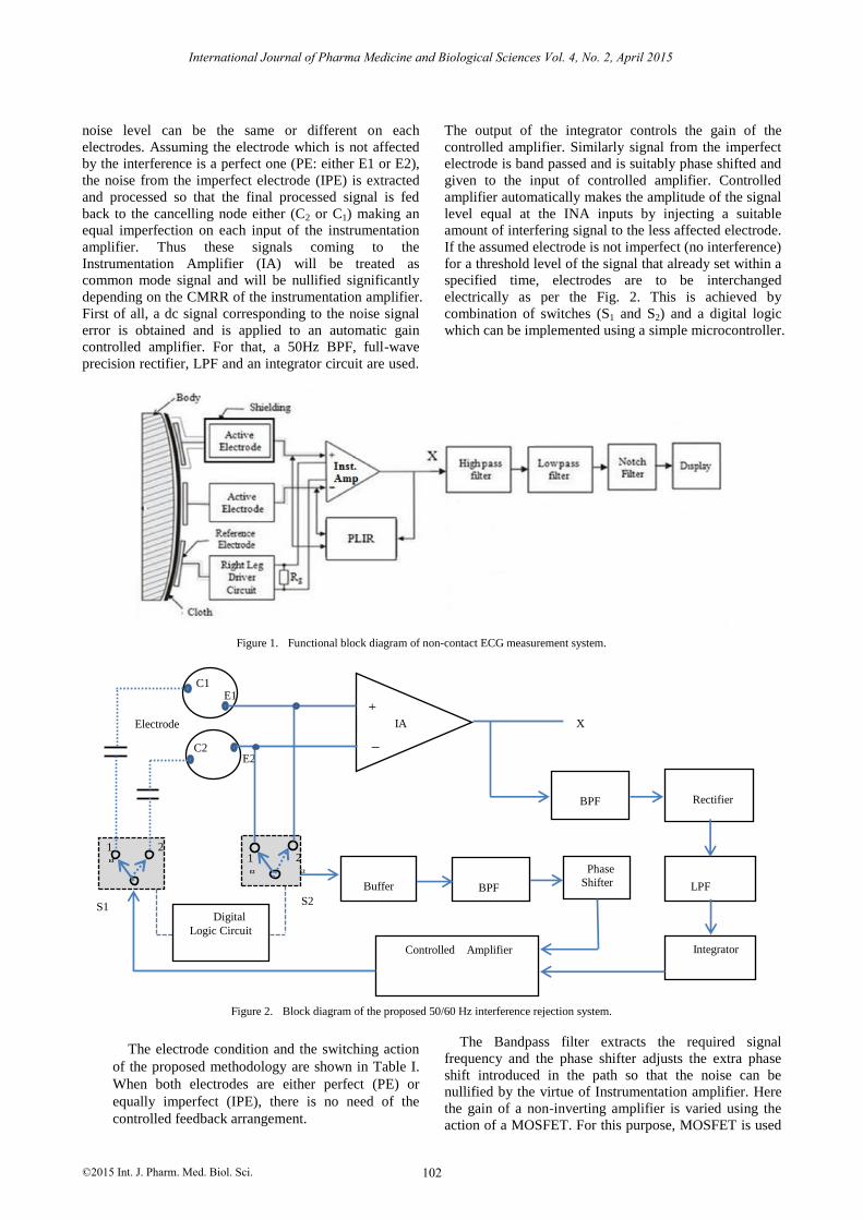
noise level can be the same or different on each
electrodes. Assuming the electrode which is not affected
by the interference is a perfect one (PE: either E1 or E2),
the noise from the imperfect electrode (IPE) is extracted
and processed so that the final processed signal is fed
back to the cancelling node either (C2 or C1) making an
equal imperfection on each input of the instrumentation
amplifier. Thus these signals coming to the
Instrumentation Amplifier (IA) will be treated as
common mode signal and will be nullified significantly
depending on the CMRR of the instrumentation amplifier.
First of all, a dc signal corresponding to the noise signal
error is obtained and is applied to an automatic gain
controlled amplifier. For that, a 50Hz BPF, full-wave
precision rectifier, LPF and an integrator circuit are used.
The output of the integrator controls the gain of the
controlled amplifier. Similarly signal from the imperfect
electrode is band passed and is suitably phase shifted and
given to the input of controlled amplifier. Controlled
amplifier automatically makes the amplitude of the signal
level equal at the INA inputs by injecting a suitable
amount of interfering signal to the less affected electrode.
If the assumed electrode is not imperfect (no interference)
for a threshold level of the signal that already set within a
specified time, electrodes are to be interchanged
electrically as per the Fig. 2. This is achieved by
combination of switches (S1 and S2) and a digital logic
which can be implemented using a simple microcontroller.
Figure 1. Functional block diagram of non-contact ECG measurement system.
Figure 2. Block diagram of the proposed 50/60 Hz interference rejection system.
The electrode condition and the switching action
of the proposed methodology are shown in Table I.
When both electrodes are either perfect (PE) or
equally imperfect (IPE), there is no need of the
controlled feedback arrangement.
The Bandpass filter extracts the required signal
frequency and the phase shifter adjusts the extra phase
shift introduced in the path so that the noise can be
nullified by the virtue of Instrumentation amplifier. Here
the gain of a non-inverting amplifier is varied using the
action of a MOSFET. For this purpose, MOSFET is used
BPF
BPF
IA
_
_
-
-
_-
_
_
_
_
=+
Rectifier
LPF
Integrator
Phase
Shifter
Buffer
Controlled Amplifier
Digital
Logic Circuit
C2 E2
E1 C1
Electrodeess
S2
2 E2
1 E2
S1
2 1
E2
X
+
_
International Journal of Pharma Medicine and Biological Sciences Vol. 4, No. 2, April 2015
102©2015 Int. J. Pharm. Med. Biol. Sci.
as the voltage variable resistor. Normally there are three
regions of operation for a MOSFET, out of which in
triode region only, it will act a voltage variable resistor.
The MOSFET should be properly biased and voltage at
the input should also be in the specified range for getting
the required action. A digital logic unit should be used for
generating control signals and for switching the
electrodes effectively on the basis of a threshold value.
The digital logic unit can be implemented using an 8 bit
micro-controller.
TABLE I. ELECTRODE NOISE AMPLITUDE AND SWITCHING POSITIONS
Electrode1 Status
Electrode 2 Status
Remarks
PE PE Both are having same
amplitude and phase
IPE IPE INA output will be ideally noiseless
PE IPE Switch position: (2,2)
IPE PE Switch position: (1,1)
IPE1 IPE2, IPE2 > IPE1 Switch position: (2,2)
IPE2 IPE1, IPE1 > IPE2 Switch position: (1,1)
III. RESULTS
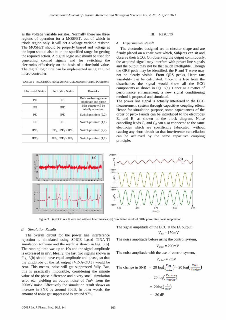
A. Experimental Result
The electrodes designed are in circular shape and are
firmly placed on a chair over which, Subjects can sit and
observe their ECG. On observing the output continuously,
the acquired signal may interfere with power line signals
and the output may not be that much intelligible. Though
the QRS peak may be identified, the P and T wave may
not be clearly visible. From QRS peaks, Heart rate
variability can be calculated. Once it is free from the
disturbance, the signal would show all the ECG
components as shown in Fig. 3(a). Hence as a matter of
performance enhancement, a new signal conditioning
method is proposed and simulated.
The power line signal is actually interfered to the ECG
measurement system through capacitive coupling effect.
Hence for simulation purpose, some capacitances of the
order of pico- Farads can be introduced to the electrodes
E1 and E2 as shown in the block diagram. Noise
cancelling leads C1 and C2 can also connected to the same
electrodes which are specifically fabricated, without
causing any short circuit so that interference cancellation
can be achieved by the same capacitive coupling
principle.
Figure 3. (a) ECG result with and without Interferences; (b) Simulation result of 50Hz power line noise suppression.
B. Simulation Results
The overall circuit for the power line interference
rejection is simulated using SPICE based TINA-TI
simulation software and the result is shown in Fig. 3(b).
The running time was up to 10s and the signal amplitude
is expressed in mV. Ideally, the last two signals shown in
Fig. 3(b) should have equal amplitude and phase, so that
the amplitude of the IA output (VINA-OUT) would be
zero. This means, noise will get suppressed fully. But,
this is practically impossible, considering the minute
value of the phase difference and a very small simulation
error etc. yielding an output noise of 7mV from the
200mV noise. Effectively the simulation result shows an
increase in SNR by around 30dB. In other words, the
amount of noise get suppressed is around 97%.
The signal amplitude of the ECG at the IA output,
Vina = 150mV
The noise amplitude before using the control system,
Vnoise = 200mV
The noise amplitude with the use of control system,
Vnoise’ = 7mV
The change in SNR = 20 log( ) – 20 log( )
= 20 log( )
= 20log( )
= -30 dB
(a) (b)
International Journal of Pharma Medicine and Biological Sciences Vol. 4, No. 2, April 2015
103©2015 Int. J. Pharm. Med. Biol. Sci.

The above calculation shows that the SNR is improved
by 30dB. This study is repeated with different values of
coupling capacitances and the result is found to be
consistent for the designed circuit as shown in Table II.
The complete circuit set up can also be tested using
LabVIEW after wiring the essential hardware part. The
filters, controlled amplifier and the switching circuits etc.
as shown in the Fig. 2 get wired up on NI ELVIS board.
TABLE II. SIMULATION ANALYSIS FOR DIFFERENT COUPLING
CAPACITANCES
Coupling
Capacitance (pF)
Vnoise amplified by
INA (mV)
Vina-out
(mV) Improvement
in SNR (dB)
0.5 49.98 1.66 29.57
1 100.12 3.31 29.62
2 200.34 6.6 29.64
IV. CONCLUSION AND FUTURE SCOPE
In this article, a noncontact ECG measurement has
been carried out and a scheme for suppressing power line
interference is also proposed and simulated. A prototype
had been built; tested and non-contact ECG signals had
been obtained from the body of many volunteers. The
developed non-contact scheme provided reliable and very
good signal quality without losing any important
morphological information compared to a conventional
ECG. The proposed scheme is very applicable if the
noncontact ECG measurement system lies adjacent to
powered electronic equipments. A variety of analog cum
digital circuits for power line interference rejection can
be designed and tested. But, the task of getting
continuous, accurate and stable non-contact ECG
measurement is a challenging one. The proposed
noncontact scheme that tested on a chair can also be
applied on bed for long term cardiovascular monitoring.
In this case some array of electrodes can be implemented
and multiplexed to avoid distortion of the ECG signal
from the body when the Subject is changing his/her
position to right or left on the bed. Moreover, the signal
obtained can be sent to the doctor using telemetry
principle.
ACKNOWLEDGMENT
The Author would like to acknowledge the help and
support received from Dr. Boby George (Asst. Professor),
Arun K P and Anoop C S (Research Scholars) of Indian
Institute of Technology Madras for completing this
research work.
REFERENCES
[1] T. Maruyama, M. Makikawa, N. Shiozawa, and Y. Fujiwara,
“ECG measurements using capacitive coupling electrodes for
man-machine emotional communication,” IEEE/ICME International Conference on Complex Medical Engineering,
Beijing, 2007, pp. 378-383.
[2] A. Schommartz, B. Eilebrecht, T. Wartzek, M. Walter, and S. Leonhardt, “Advances in modern capacitive ECG systems for
continuous cardiovascular monitoring,” Acta Polytechnica, vol. 51, no. 5, pp. 100-105, 2011.
[3] P. Richardson, “The insulated electrode,” in Proceedings of the
20th Annual Conference on Engineering in Medicine and Biology, Boston, vol. 9, pp. 157, 1967.
[4] M. Ishijima, “Monitoring of electrocardiograms in bed without utilizing body surface electrodes,” IEEE Transactions on
Biomedical Engineering, vol. 40, no. 6, pp. 593-594, 1993.
[5] Y. Lim, K. Kim, and K. Park, “The ECG measurement in the bathtub using the insulated electrodes,” 26th Annual International
Conference of the IEEE EMBS, vol. 1, pp. 2383-2385, 2004. [6] K. Kim, Y. Lim, and K. Park, “The electrically noncontacting
ECG measurement on the toilet seat using the capacitively-
coupled insulated electrodes,” 26th Annual International Conference of the IEEE EMBS, vol. 1, pp. 2375-2378, 2004.
[7] Y. Lim, K. Kim, and S. Park, “ECG measurement on a chair without conductive contact,” IEEE Transactions on Biomedical
Engineering, vol. 53, pp. 956-959, 2006.
[8] T. Kato, A. Ueno, S. Kataoka, H. Hoshino, and Y. Ishiyama, “An application of capacitive electrode for detecting electrocardiogram
of neonates and infants,” 28th Annual International Conference of the IEEE EMBS, vol. 1, pp. 916-919, 2006.
[9] S. Leonhardt and A. Aleksandrowicz, “Non-contact ECG
monitoring for automotive application,” 5th International Summer School and Symposium on Medical Devices and Biosensors, Hong
Kong, pp. 183-185, 2008. [10] B. B. Winter and J. G. Webster, “Driven-right-leg circuit design,”
IEEE Transactions on Biomedical Engineering, vol. BME-30, no.
1, pp. 62-66, 1983. [11] T. Degen and H. Jackel, “Enhancing interference rejection of
preamplified electrodes by automated gain adaption,” IEEE Transactions on Biomedical Engineering, vol. 51, pp. 2031-2039,
2004.
[12] N. Hamza, L. Khriji, and R. Tourki, “Interference reduction in ECG signal acquisition: Ground electrode removal (case study),”
International Conference on Computer Medical Applications (ICCMA), 2013, pp. 1-4.
[13] V. Bhateja, S. Urooj, R. Verma, and R. Mehrotra, “A novel
approach for suppression of powerline interference and impulse noise in ECG signals,” International Conference on Multimedia,
Signal Processing and Communication Technologies (IMPACT), 2013, pp. 103-107.
[14] Y. M. Chi, T. P. Jung, and G. Cauwenberghs, “Dry-contact and
noncontact biopotential electrodes: Methodological review,” IEEE Reviews in Biomedical Engineering, vol. 3, pp. 106-119,
2010. [15] B. S. Lin, et al., “Development of novel non-contact electrodes
for mobile electrocardiogram monitoring system,” IEEE Journal
of Translational Engineering in Health and Medicine, vol. 1, pp. 1-8, 2013.
[16] K. V. A. Muneer, “Noncontact ECG Recording Instrument for Continuous Cardiovascular Monitoring,” IEEE-EMBS
International conference on Biomedical and Health Informatics
(BHI), Spain, 2014, pp. 269-272. [17] L. Smolarik, A. Libosvarova, D. Mudroncik, and P. Schreiber,
“Non-contact ECG signal processing,” 6th IEEE International Conference on Intelligent Systems(IS), Sofia, 2012, pp. 349-354.
[18] P. Prasopsin, B. Pholpoke, S. Tepwimonpetkun, and W.
Wattanapanitch, “A compact low-power mixed-signal architecture for powerline interference rejection in biopotential
analog front ends,” IEEE Biomedical Circuits and Systems Conference (BioCAS), pp. 196-199, 2014.
[19] P. Guochen and M. F. Bocko, “Non-contact ECG employing
signal compensation,” IEEE International Conference on Biomedical Circuits and Systems.(BioCAS), Rotterdam, 2013, pp.
57-60.
International Journal of Pharma Medicine and Biological Sciences Vol. 4, No. 2, April 2015
104©2015 Int. J. Pharm. Med. Biol. Sci.

Ahammed Muneer K V received the B.Tech degree in electronics and communication
engineering from College of Engineering
Trivandrum, Kerala, India in 2002 and completed his post-graduation, M.Tech in
control and instrumentation systems from Indian Institute of Technology, Madras, India
in 2012. He has been working as an assistant
professor in electronics engineering in various universities of Kerala, India and has
more than ten years of teaching experience.
He has got the best M.Tech project award from Indian Institute of Technology Madras in 2012 for his thesis work. He recently published a
paper in IEEE-EMBS international conference titled “Non-contact ECG
recording Instrument for Continuous Cardiovascular Monitoring”. Presently he is working as an assistant professor in Govt. Engineeering
College Kozhikode, Kerala, India. His research area includes electronic instrumentation and sensors, signal processing etc. He is pursuing his
PhD degree in National Institute of Technology, Calicut, India and the
current research focus is on biomedical image processing.
International Journal of Pharma Medicine and Biological Sciences Vol. 4, No. 2, April 2015
105©2015 Int. J. Pharm. Med. Biol. Sci.