a refined 1d fe model for the application … · aeroelasticity of composite wings alberto varello...
TRANSCRIPT

IV International Conference on Computational Methods for Coupled Problems in Science and EngineeringCOUPLED PROBLEMS 2011
M. Papadrakakis, E. Onate and B. Schrefler (Eds)
A REFINED 1D FE MODEL FOR THE APPLICATION TOAEROELASTICITY OF COMPOSITE WINGS
Alberto Varello∗†, Marco Petrolo∗† and Erasmo Carrera∗
∗Department of Aeronautic and Space Engineering, Politecnico di TorinoCorso Duca degli Abruzzi 24, 10129 Torino, Italye-mail: [email protected], www.mul2.com
†Institut Jean Le Rond d’Alembert, UMR 7190 CNRS, Univ Paris 6Case 162, Tour 55-65, 4, Place Jussieu, 75252 Paris, France
e-mail: [email protected], www.mul2.com
Key words: Aeroelasticity, FE-VLM Coupling, Refined Beam Models, Composite Wings,Unified Formulation
Abstract. The extension of a hierarchical one-dimensional structural model to aeroelas-ticity is the subject of the present paper. The aerodynamic model is based on the VortexLattice Method, VLM, whereas the refined 1D model is based on the Carrera Unified For-mulation, CUF. Airfoil in-plane deformation and warping are introduced by enriching thedisplacement field over the cross-section of the wing. Linear to fourth-order expansionsare adopted and classical beam theories (Euler-Bernoulli and Timoshenko) are obtainedas particular cases. The VLM aerodynamic theory is coupled with the structural finiteelement model via an appropriate adaptation of the Infinite Plate Spline method. Theaeroelastic tailoring is investigated for several wing configurations (by varying aspect ra-tio, airfoil geometry and sweep angle) and an excellent agreement with MD NASTRANsolution is provided for structural and aeroelastic cases. The effectiveness of higher-ordermodels for an accurate evaluation of aeroelastic response of isotropic and composite wingsis shown.
1 INTRODUCTION
Composite materials are widely used nowadays in a large variety of applications andengineering fields. The advantages related to their spread are becoming so significant thatcomposites are by now a must for state-of-the-art manufacturing technology.
The requirements of weight saving and structural efficiency for aerospace systems suchas rotor blades, aircraft wings, and helicopter rotor blades are leading to a wide use ofstructures in the form of composite thin-walled beams. This makes the accurate evaluationof the response of deformable lifting bodies (LBs) when subjected to steady and unsteady
1
Alberto Varello, Marco Petrolo and Erasmo Carrera
aerodynamic loadings an even more challenging issue for the aeroelastic design of aerospacevehicles [8]. Over the last decades, many significant contributions have been given instructural, aerodynamic, and aeroelastic coupling modeling [12]. A relevant review articleabout recent advances in describing fluid-structure interaction is found in Dowell and Hall[9].
Composite beam-like structures can be analyzed by means of beam models providedthat a number of non-classical effects such as large torsional warping are incorporated.Detailed structural and aeroelastic models are essential to fully exploit non-classical effectsin design due to the properties characterizing advanced composite material structures,such as anisotropy, heterogeneity and transverse shear flexibility [14]. A detailed review ofthe recent development of beam models can be found in [20]. A considerable amount ofwork was done in trying to improve the global response of classical beam theories [11, 19]using appropriate shear correction factors, as described by Timoshenko [19]. El Fatmi [10]improved on the displacement field over the beam cross-section by introducing a warpingfunction to refine the description of normal and shear stress of the beam. An asymptotictype expansion in conjunction with variational methods (VABS) was proposed by Yu andco-workers [22]. Generalized beam theories (GBT) have improved classical theories byusing a piece-wise beam description of thin-walled sections [18].
Among the various extensions of refined beam models to aeroelasticity, the work done byLibrescu and Song [16] on divergence instability of swept-forward wings made of compositematerials is mentioned. A thin-walled beam model was implemented which incorporatedthe anisotropy of the material, transverse shear deformation and warping effects.
Carrera and co-authors have recently proposed refined 1D theories with only generalizeddisplacement variables for the analysis of compact and thin-walled sections/airfoils. Higher-order finite elements are obtained in the framework of the Carrera Unified Formulation,CUF, which considers the order of the model as a free-parameter of the analysis. Thistechnique has been developed over the last decade for plate/shell models [2] and it hasrecently been extended to beam static and dynamic modeling [4, 5, 6].
The present work couples a refined 1D model based on CUF with the Vortex LatticeMethod (VLM) for the analysis of static aeroelastic response of aircraft wings. Theaerodynamic load transferring is based on the work presented by Demasi and Livne [8] viathe Infinite Plate Spline method [13]. In the proposed formulation (see Varello et al.[21]),the computation of linear steady aerodynamic loads refers to the VLM presented by Katzand Plotkin [15].
2 PRELIMINARIES
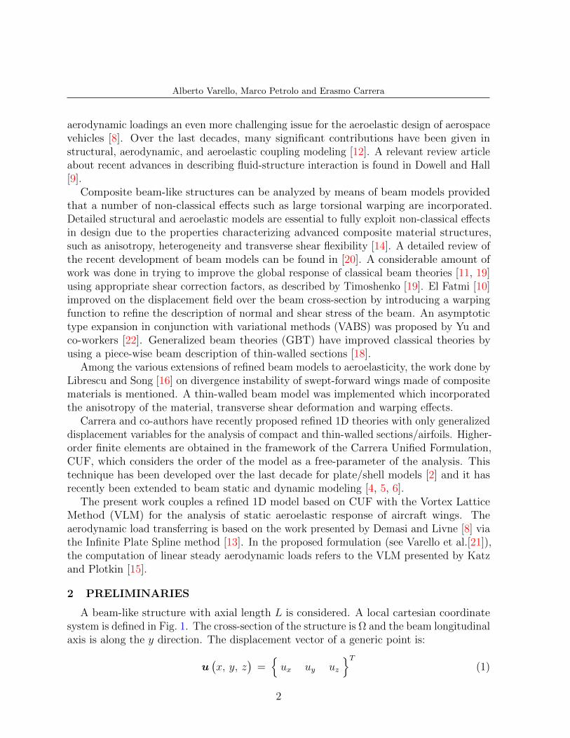
A beam-like structure with axial length L is considered. A local cartesian coordinatesystem is defined in Fig. 1. The cross-section of the structure is Ω and the beam longitudinalaxis is along the y direction. The displacement vector of a generic point is:
u(x, y, z
)=ux uy uz
T(1)
2
Alberto Varello, Marco Petrolo and Erasmo Carrera
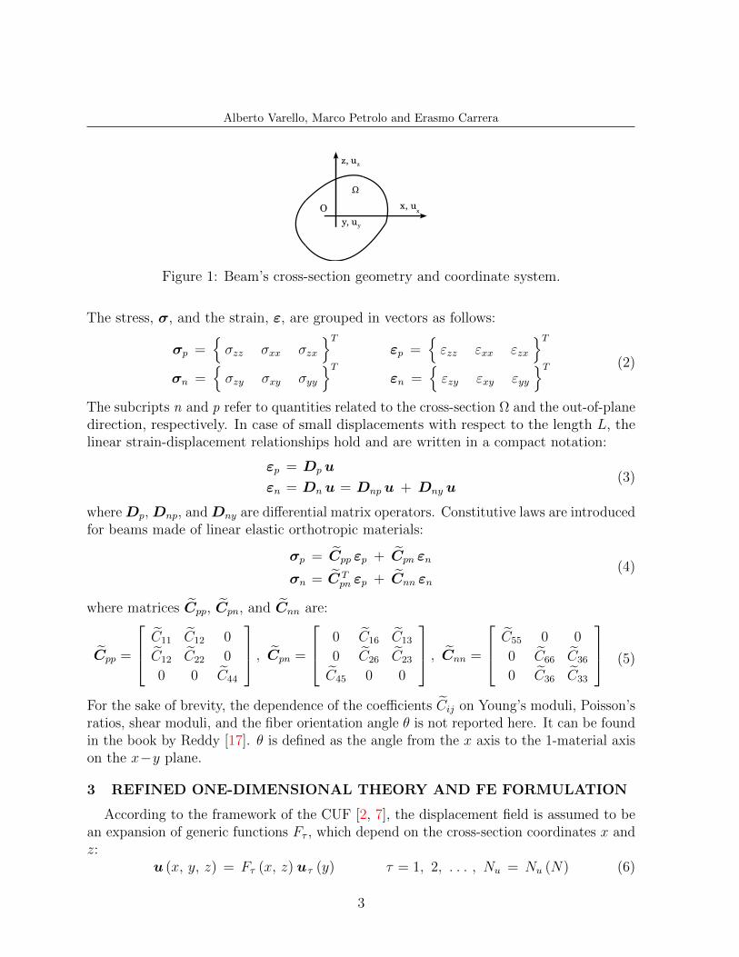
Figure 1: Beam’s cross-section geometry and coordinate system.
The stress, σ, and the strain, ε, are grouped in vectors as follows:
σp =σzz σxx σzx
Tεp =
εzz εxx εzx
Tσn =
σzy σxy σyy
Tεn =
εzy εxy εyy
T (2)
The subcripts n and p refer to quantities related to the cross-section Ω and the out-of-planedirection, respectively. In case of small displacements with respect to the length L, thelinear strain-displacement relationships hold and are written in a compact notation:
εp = Dp u
εn = Dn u = Dnp u + Dny u(3)
whereDp, Dnp, andDny are differential matrix operators. Constitutive laws are introducedfor beams made of linear elastic orthotropic materials:
σp = Cpp εp + Cpn εn
σn = C Tpn εp + Cnn εn
(4)
where matrices Cpp, Cpn, and Cnn are:
Cpp =
C11 C12 0
C12 C22 0
0 0 C44
, Cpn =
0 C16 C13
0 C26 C23
C45 0 0
, Cnn =
C55 0 0
0 C66 C36
0 C36 C33
(5)
For the sake of brevity, the dependence of the coefficients Cij on Young’s moduli, Poisson’sratios, shear moduli, and the fiber orientation angle θ is not reported here. It can be foundin the book by Reddy [17]. θ is defined as the angle from the x axis to the 1-material axison the x−y plane.
3 REFINED ONE-DIMENSIONAL THEORY AND FE FORMULATION
According to the framework of the CUF [2, 7], the displacement field is assumed to bean expansion of generic functions Fτ , which depend on the cross-section coordinates x andz:
u (x, y, z) = Fτ (x, z) uτ (y) τ = 1, 2, . . . , Nu = Nu (N) (6)
3

Alberto Varello, Marco Petrolo and Erasmo Carrera
The number of terms Nu depends on the expansion order N , which is a free parameterof the formulation. Mac Laurin’s polynomials x iz j are chosen as cross-section functionsFτ and hence Eq. 6 is a Taylor-like expansion. Most displacement-based theories canbe formulated on the basis of the above generic kinematic field. Classical beam modelssuch as Timoshenko’s (TBM) [19] and Euler-Bernoulli’s (EBBM) [11] are easily derivedfrom the linear expansion, N = 1 [5]. Models having constant and linear distributions ofthe in-plane displacements components, ux and uz, require opportunely reduced materialcoefficients to overcome Poisson’s locking effect [3]. For the sake of brevity, the explicitexpression for these coefficients is not reported here, but can be found in [4].
The FE approach is herein adopted to discretize the structure along the y axis. Byintroducing the shape functions Ni and the nodal displacement vector q, the displacementfield becomes:
u (x, y, z) = Fτ (x, z)Ni (y) qτi i = 1, 2, . . . , NN (7)
where qτi =quxτi quyτi quyτi
Tcontains the degrees of freedom of the τ th expansion
term corresponding to the ith element node. Elements with a number of nodes NN equalto 4 are formulated and hereinafter referred as B4. A cubic approximation along the yaxis is adopted [1].
The stiffness matrix of the elements is built via the Principle of Virtual Displacements:
δLint =
∫V
(δεTn σn + δεTp σp
)dV = δLext (8)
where Lint stands for the strain energy and Lext is the work of external loadings. δ standsfor virtual variation. By using Eqs. 3, 4, and 7 the internal virtual work becomes:
δLint = δqTτi Kij τ s qsj (9)
K ij τ s is the 3× 3 fundamental nucleus of the structural stiffness matrix. For the sake ofbrevity, its explicit expression is not reported here, but it can be found in [20]. It shouldbe noted that no assumptions on the expansion order have been made. Therefore, it ispossible to obtain refined beam models without changing the formal expression of thenucleus components. Shear locking is corrected through selective integration [1].
4 STRUCTURAL AND AERODYNAMIC NOTATIONS
The proposed beam model can easily analyze non-planar wing configurations witharbitrary orientation in the 3D space, such as tapered wings with dihedals and sweepangles.
The aerodynamic method here chosen is the Vortex Lattice Method (VLM) [15]. Theaerodynamic mesh, which consists in a lattice of NAP quadrilateral panels, lies on areference trapezoidal surface with 2 edges parallel to the wind direction. As shown in
4

Alberto Varello, Marco Petrolo and Erasmo Carrera
yglob
x loc
x loc’ xglob
yloc
yloc’
z loc
z glob z loc’
V
Figure 2: One-dimensional structural mesh and two-dimensional aerodynamic mesh of thewing structure.
Fig. 2, a second coordinate system xloc′−yloc′−zloc′ is introduced so that the referencesurface lies on the xloc′−yloc′ plane. A global coordinate system x−y−z is placed onthe airfoil’s leading edge point at the root wing section so that x and xloc′ axes are bothparallel to the free stream velocity V∞ (see Fig. 2).
The wing is modeled with a straight beam. The structural FE mesh is contained alongthe yloc axis, which is on the trapezoidal reference surface. The fundamental nucleus (seeEq. 9) was derived in the local coordinate system. The notation is slightly modified byintroducing the subscript “loc” to reflect this fact:
δLint = δqTτi loc Kij τ sloc qsj loc = δqTτi
[eT · K ij τ s
loc · e]qsj = δqTτi K
ij τ s qsj (10)
where e is the 3× 3 rotation matrix relating the global and the local coordinate systems.
5 SPLINING AND AEROELASTIC FORMULATION
The present advanced beam model allows a very accurate calculation of the displacementfield at any point of the three-dimensional wing. Based on this property, the Infinite PlateSpline method [8, 13] was shown (see [21]) to be the ideal choice for the aerodynamic loadtransferring with the advanced multi-fidelity beam model presented in this work. For thesake of brevity, the final expressions relating the displacements at aerodynamic load pointsand slopes at aerodynamic control points to the nodal DOFs vector of the whole structureare reported:
Z loc′ = A?3 · q
dZ loc′
dxloc′=
dZ loc′
dx= A3 · q (11)
The coordinate system for the splining is the local′ one. More details about the adaptationof the IPS to the CUF-beam via a set of pseudo-structural points can be found in [21, 20].The derivation of aerodynamic loads is now faced. According to the VLM [15], the
5
Alberto Varello, Marco Petrolo and Erasmo Carrera
pressures acting on the wing are transferred as lift forces located on load points of theaerodynamic panels and perpendicular to the wind direction:
L =1
2ρ∞ V
2∞ I
D · ∆p =1
2ρ∞ V
2∞ I
D ·[AD]−1 · w (12)
where ∆p contains the dimensionless pressure acting on all the load points, normalizedwith respect to the dynamic pressure. ID contains the panels’ geometrical data. The VLMallows the dimensionless normalwash w, normalized with respect to V∞, to be describedas a function of vector ∆p by means of the Aerodynamic Influence Coefficient Matrix AD.
In the steady case, considering that the structure changes configuration when it deforms,the boundary condition used for the Vortex Lattice formulation imposes the dimensionlessnormalwash to equal the slope at the control points:
w =dZ loc′
dxloc′(13)
The transfer from loads at the aerodynamic points to the energetically equivalent loadsat structural nodes is performed via the Principle of Virtual Displacements. All the liftforces are parallel to the zloc′ axis, hence:
δW = δZT
loc′ · L = δqT · A?3
T· 1
2ρ∞ V
2∞ I
D ·[AD]−1 · A3 · q = δqT · Lstr
⇒ Lstr = −Kaero · q(14)
where the negative sign is adopted for the sake of convenience. Such a term can go to theleft hand side of the aeroelastic equation system and summed up to the structural stiffnessmatrix:
Kstr · q = Lstr = −Kaero · q (15)[Kstr + Kaero
]· q = 0 Kaeroelastic · q = 0 (16)
where Kaeroelastic is the aeroelastic stiffness matrix. The stiffness of the system now takesinto account the aerodynamic loads due to the deformed configuration. From Eq. 16 itappears that there is no motion. It occurs because the angle of attack so far considered iszero. To solve this problem, a different from zero angle of attack is assigned to the wingand the corresponding aerodynamic lift forces acting on the panels are computed. Thewall tangency condition is now imposed at the control point of each panel by setting thedimensionless normalwash to be equal to the local slope:
w = tan(π − α
)(17)
where the angle of attack α is a small quantity (linear aerodynamic model). Followingthe same procedure used to build Lstr, the energetically equivalent nodal loads LRHS (thesubscript RHS means Right Hand Side) are:
LRHS =1
2ρ∞ V
2∞ tan
(π − α
)A?
3
T· ID
[AD]−1
d (18)
6

Alberto Varello, Marco Petrolo and Erasmo Carrera
(a) NACA 2415 with 3 cells (b) Rectangular section
Figure 3: Cross-sections used for the wing configurations.
where d stands for a NAP × 1 vector of ones. More details about this procedure can befound in [20]. In conclusion, the final aeroelastic equation to be solved is:
Kaeroelastic · q = LRHS (19)
Equation 19 allows nodal displacement vector q to be computed. Now that the right handside is different from zero, we have a solution.
6 RESULTS AND DISCUSSION
A number of wings with different geometries, layout and loadings are considered. Twodifferent solutions are investigated and compared in this work. The first one coincides withthe static structural analysis, hereinafter referred as SSA, and involves only the structuralstiffness matrix by disabling the aerodynamic matrix Kaero. The second solution is thestatic aeroelastic analysis (SAA) which solves the aeroelastic system (Eq. 19) by adding theaerodynamic stiffness matrix to the elastic one. Unless otherwise specified, the wings aresubjected to a pure aerodynamic loading (vector LRHS). Cantilever boundary conditionon half-wings is accounted for and the symmetry condition is exploited in the aerodynamiccomputation.
A swept tapered wing is first taken into account. A half-wing is modeled via a cantileverbeam by using the following data: length L = 5 m, root chord croot = 1.6 m, taper ratioλ = 0.25, and sweep angle Λ = +13.5°. The cross-section is a thin-walled NACA 2415airfoil, which is subdivided into three cells by two longerons along the spanwise directionat 25% and 75% of the chord (see Fig. 3a). An isotropic aluminium (Young’s modulusE = 69 GPa and Poisson’s ratio ν = 0.33) is considered.
A convergence study is carried out to evaluate the combined effect of the number offinite elements NEL and the expansion order N on the solution. The mechanics of thebeam is described in terms of the maximum vertical displacement uzmax, which is locatedat the trailing edge of the tip cross-section. The results for SSA and SAA are shown inTables 1 and 2, respectively. uzmax increases with N for any mesh, to such an extentthat no remarkable differences are detected for high-order expansion. The numericalconvergence on NEL is achieved both for SSA and SAA. Linear theories EBBM, TBM,and N = 1 are unable to handle any torsional behavior. Poisson’s locking correction is notsufficient to make them effective in computing the maximum displacement.
7

Alberto Varello, Marco Petrolo and Erasmo Carrera
Table 1: Convergence study: effect of the number of B4 elements on uzmax [mm] fordifferent beam models. Swept tapered wing. V∞ = 50 m/s, α = 3°, 4× 40 panels. SSA.
NEL EBBM TBM N = 1 N = 2 N = 3 N = 4
2 4.2749 4.2829 4.2909 4.4309 4.9598 5.10365 3.1768 3.1842 3.1965 3.6408 3.8045 3.885810 3.0401 3.0473 3.0605 3.4701 3.5785 3.631620 3.0071 3.0144 3.0277 3.4097 3.4854 3.537740 2.9990 3.0062 3.0196 3.3920 3.4440 3.4802
-13.69% -13.49% -13.10% -2.383% -0.886% +0.155%
MD NASTRAN-solid (sol 101): 3.4748
EBBM
N = 3
Figure 4: Tridimensional deformation of the swept tapered wing. Pz = −7.2 kN. SAA.
Table 2: Convergence study: effect of the number of B4 elements on uzmax [mm] fordifferent beam models. Swept tapered wing. V∞ = 50 m/s, α = 3°, 4× 40 panels. SAA.
NEL EBBM TBM N = 1 N = 2 N = 3 N = 4
2 4.2747 4.2827 4.2904 4.4236 4.9456 5.09155 3.1767 3.1841 3.1959 3.6307 3.7930 3.874310 3.0400 3.0472 3.0598 3.4597 3.5678 3.620620 3.0071 3.0143 3.0270 3.3993 3.4749 3.526940 2.9989 3.0061 3.0189 3.3816 3.4337 3.4695
-13.40% -13.20% -12.83% -2.353% -0.849% +0.185%
MD NASTRAN-shell (sol 144): 3.4631
8
Alberto Varello, Marco Petrolo and Erasmo Carrera
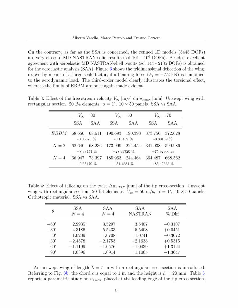
On the contrary, as far as the SSA is concerned, the refined 1D models (5445 DOFs)are very close to MD NASTRAN-solid results (sol 101 - 106 DOFs). Besides, excellentagreement with aeroelastic MD NASTRAN-shell results (sol 144 - 2135 DOFs) is obtainedfor the aeroelastic analysis (SAA). Figure 3 shows the tridimensional deflection of the wing,drawn by means of a large scale factor, if a bending force (Pz = −7.2 kN) is combinedto the aerodynamic load. The third-order model clearly illustrates the torsional effect,whereas the limits of EBBM are once again made evident.
Table 3: Effect of the free stream velocity V∞ [m/s] on uzmax [mm]. Unswept wing withrectangular section. 20 B4 elements. α = 1°, 10× 50 panels. SSA vs SAA.
V∞ = 30 V∞ = 50 V∞ = 70
SSA SAA SSA SAA SSA SAA
EBBM 68.650 68.611 190.693 190.398 373.756 372.628-0.05573 % -0.15459 % -0.30189 %
N = 2 62.640 68.236 173.999 224.454 341.038 599.986+8.93451 % +28.99720 % +75.92906 %
N = 4 66.947 73.397 185.963 244.464 364.487 668.562+9.63479 % +31.4584 % +83.42555 %
Table 4: Effect of tailoring on the twist ∆uz TIP [mm] of the tip cross-section. Unsweptwing with rectangular section. 20 B4 elements. V∞ = 50 m/s, α = 1°, 10 × 50 panels.Orthotropic material. SSA vs SAA.
θSSAN = 4
SAAN = 4
SAANASTRAN
SAA% Diff
−60° 2.9935 3.5297 3.5407 −0.3107−30° 4.3186 5.5433 5.5408 +0.0451
0° 1.0209 1.0708 1.0741 −0.307230° −2.4578 −2.1753 −2.1638 +0.531560° −1.1199 −1.0576 −1.0439 +1.312490° 1.0396 1.0914 1.1065 −1.3647
An unswept wing of length L = 5 m with a rectangular cross-section is introduced.Referring to Fig. 3b, the chord c is equal to 1 m and the height is h = 20 mm. Table 3reports a parametric study on uzmax, placed at the leading edge of the tip cross-section,
9

Alberto Varello, Marco Petrolo and Erasmo Carrera
-3
-2
-1
0
1
2
3
4
5
6
-100 -80 -60 -40 -20 0 20 40 60 80 100
∆ u z
TIP
[m
m]
θ [deg]
SSA N = 4
SAA N = 4
SAA NASTRAN
(a) Twist
80
100
120
140
160
180
200
220
-100 -80 -60 -40 -20 0 20 40 60 80 100
u z T
IP [
mm
]
θ [deg]
SSA N = 4
SAA N = 4
SAA NASTRAN
(b) Bending
Figure 5: Effect of tailoring on the twist and bending of the tip cross-section. Unsweptwing with rectangular section. Orthotropic material. SSA vs SAA.
as the free stream velocity changes. While uzmax increases linearly with the square of V∞for SSA, the same does not occur for SAA. The contribution of Kaero to system stiffnessbecomes more evident as V∞ increases and the difference from SSA can become verysignificant for V∞ = 70 m/s. This difference increases with the expansion order N , whichenhances the flexibility of the structure. EBBM is ineffective in describing the differencebetween structural and aeroelastic behavior.
The length L of the unswept wing is further extended to 10 m. The chord c is equal to1 m and the height of the rectangular section is h = 100 mm. A composite material isintroduced to analyze the well-known aeroelastic tailoring. Young’s modulus along thelongitudinal axis EL is equal to 20.5 GPa, whereas those along the transverse directionsare equal to 10 GPa. Poisson’s ratio ν = 0.25 and the shear modulus G = 5 GPa are thesame in all directions. Table 4 shows the effect of the lamination θ on the torsion of thetip cross-section due to the only aerodynamic pressure. The quantity ∆uz is defined asthe difference of uz between leading and trailing edges. The aeroelastic tailoring is moreevident for the wing twist evaluation as it is presented in Fig. 5a.
The comparison of SSA and SAA underlines the importance of the contribution ofKaero in the case N = 4 to evaluate the aeroelastic behavior of composite wings. Whilethe curve related to SSA is essentially symmetrical with respect to the θ = 0° lamination,the aeroelastic analysis shows a trend which is far from symmetrical. In general, theaeroelastic analysis leads the twist of the unswept wing to be higher compared to thestructural solution as the lamination changes, expecially for negative values of θ. Thesame result occurs for bending behavior as shown in Fig. 5b, where only the SSA caseobtains an almost symmetrical curve. The excellent agreement between the fourth-orderbeam model and MD NASTRAN-shell (sol 144) to describe the aeroelastic response oforthotropic wings with generic orientation is again striking.
10
Alberto Varello, Marco Petrolo and Erasmo Carrera
7 CONCLUSIONS
This paper has extended the Vortex Lattice Method and a refined one-dimensionalstructural model for the analysis of anisotropic wings. Advanced 1D finite elements havebeen obtained via the Carrera Unified Formulation which allows any order theory to beobtained in a hierarchical manner. The static aeroelastic and structural response of wingswith different geometries and cross-sections has been analyzed. Isotropic and compositematerials has been considered.
The CUF-VLM structural and coupling models have been assessed and comparedwith MD NASTRAN results. The effectiveness of higher-order models for an accurateanalysis of aircraft wings exposed to a free stream has been shown in respect to classicaltheories. Comparison of structural and aeroelastic solutions has underlined the importanceof the contribution of aerodynamic stiffness. The effect of aeroelastic tailoring has beeninvestigated and excellent agreement with MD NASTRAN in evaluating the aeroelasticresponse of composite wings has been documented. Future works will focus on aeroelasticstatic and dynamic stability analyses (divergence and flutter).
REFERENCES
[1] K.J. Bathe. Finite element procedure. Prentice hall, Upper Saddle River, New Jersey,1996.
[2] E. Carrera. Theories and finite elements for multilayered plates and shells: a unifiedcompact formulation with numerical assessment and benchmarking. Archives ofComputational Methods in Engineering, 10(3):216–296, 2003.
[3] E. Carrera and S. Brischetto. Analysis of thickness locking in classical, refined andmixed multilayered plate theories. Composite Structures, 82(4):549–562, 2008.
[4] E. Carrera and G. Giunta. Refined beam theories based on a unified formulation.International Journal of Applied Mechanics, 2(1):117–143, 2010.
[5] E. Carrera, G. Giunta, P. Nali, and M. Petrolo. Refined beam elements with arbitrarycross-section geometries. Computers and Structures, 88(5–6):283–293, 2010. DOI:10.1016/j.compstruc.2009.11.002.
[6] E. Carrera, M. Petrolo, and A. Varello. Advanced beam formulations for free vibrationanalysis of conventional and joined wings. Journal of Aerospace Engineering, 2010.In press.
[7] L. Demasi. ∞3 hierarchy plate theories for thick and thin composite plates: thegeneralized unified formulation. Composite Structures, 84(3):256–270, 2008.
11

Alberto Varello, Marco Petrolo and Erasmo Carrera
[8] L. Demasi and E. Livne. Dynamic aeroelasticity of structural nonlinear configurationsusing linear modally reduced aerodynamic generalized forces. AIAA Journal, 47(1):71–90, 2009.
[9] E.H. Dowell and K.C. Hall. Modeling of fluid-structure interaction. Annual Reviewof Fluid Mechanics, 33:445–490, 2001.
[10] R. El Fatmi. Non-uniform warping including the effects of torsion and shear forces.Part I: A general beam theory. International Journal of Solids and Structures,44(18-19):5912–5929, 2007.
[11] L. Euler. De curvis elasticis. Bousquet, Lausanne and Geneva, 1744.
[12] Y.C. Fung. An Introduction to the Theory of Aeroelasticity. Dover Publications, 2008.
[13] R. Harder and R.N. Desmarais. Interpolation using surface splines. Journal of Aircraft,9(2):189–192, 1972.
[14] K. Kapania and S. Raciti. Recent advances in analysis of laminated beams and plates,part I: Shear effects and buckling. AIAA Journal, 27(7):923–935, 1989.
[15] J. Katz and A. Plotkin. Low-Speed Aerodynamics. Cambridge University Press, 2001.
[16] L. Librescu and O. Song. On the static aeroelastic tailoring of composite aircraft sweptwings modelled as thin-walled beam structures. Composites Engineering, 2:497–512,1992.
[17] J.N. Reddy. Mechanics of laminated composite plates and shells. Theory and Analysis.CRC Press, 2nd edition, 2004.
[18] N. Silvestre and D. Camotim. First-order generalised beam theory for arbitraryorthotropic materials. Thin-Walled Structures, 40(9):791–820, 2002.
[19] S.P. Timoshenko and J.N. Goodier. Theory of elasticity. McGraw-Hill, New York,1970.
[20] A. Varello, E. Carrera, and L. Demasi. Vortex lattice method coupled with advancedone-dimensional structural models. Journal of Aeroelasticity and Structural Dynamics,2011. Submitted.
[21] A. Varello, L. Demasi, E. Carrera, and G. Giunta. An improved beam formulationfor aeroelastic applications. In 51st AIAA/ASME/ASCE/AHS/ASC Structures,Structural Dynamics, and Materials Conference, AIAA Paper 2010-3032, Orlando,Florida, 12-15 April 2010.
[22] W. Yu, V.V. Volovoi, D.H. Hodges, and X. Hong. Validation of the variationalasymptotic beam sectional analysis (VABS). AIAA Journal, 40(10):2105–2113, 2002.
12