a redundancy strategy for high-availability power systems ... · a new redundancy strategy for...
TRANSCRIPT

© 2012 IBM Corporation
A New Redundancy Strategy for
High-Availability Power Systems
Kevin Covi
IBM STG High-End Server Development

© 2012 IBM Corporation2 A New Redundancy Strategy for High-Availability Systems K. Covi1 November 2012
Outline
�RAS Philosophy
�Review
– Power 6 – Traditional approach
– Power 7 – Hybrid approach
�Load lines and Redundancy
�New architecture

© 2012 IBM Corporation3 A New Redundancy Strategy for High-Availability Systems K. Covi1 November 2012
RAS Philosophy
�Goal: 100% Availability
– High-end server should never go down
�Conventional implementation
– Full redundancy
– No single points of failure due to active parts
– Full diagnostics with 100% Error Detection & FRU ID
– Concurrent replacement of faulty hardware

© 2012 IBM Corporation4 A New Redundancy Strategy for High-Availability Systems K. Covi1 November 2012
Power 6 Processor Book Power
�DCA (Distributed Converter Assembly)
–15 voltage levels
–1600 amps total current
–Technology: Multi-phase synchronous buck (60 phases)
�RAS
–1+1 redundant � replace after 1st failure
Power 6 DCA
Bus converters VRM’s

© 2012 IBM Corporation5 A New Redundancy Strategy for High-Availability Systems K. Covi1 November 2012
Lessons learned from Power 6
�Designing for 100% concurrent replacement results in poor
efficiency
�DCAs must be closer to load to reduce distribution losses!

© 2012 IBM Corporation6 A New Redundancy Strategy for High-Availability Systems K. Covi1 November 2012
DCA
DCA
Solution to efficiency problem
PRM* VTM* Load44V 40V 1V
Regulation Current multiplication
Power 7
Bus
Converter*
OK for DCA to be far away from loadHigh current produced
close to load
350V
Reducedlosses
Negligiblelosses
DCA too far away from load!
Bus
Converter*Load
11V 1VVRM
Power 6
350V
High copper losses!
*

© 2012 IBM Corporation7 A New Redundancy Strategy for High-Availability Systems K. Covi1 November 2012
Power 795 Processor Book Power
� DCA
– 16 voltage levels
– 200 amps total current
– Technology: Vicor Factorized Power
� Processor board
– 8 voltage levels
– 2475 amps of logic current
– Technology: Vicor Factorized Power
� RAS
– DCA: 1+1 � replace on 1st failure
– VTM: N+2 � replace on 2nd failure
Power 7 DCA
Power distribution board
Bus converters
PRM’s
VTM’s (37x) ORing FET’s (222x)

© 2012 IBM Corporation8 A New Redundancy Strategy for High-Availability Systems K. Covi1 November 2012
Power 775 Supercomputing Drawer
� Factorized Power is ideally suited for IBM Power 775 Supercomputer, where high
power density was essential
� Contains compute power of 8 Power 795 processor books
� Specifications
– 256 processor cores
– 24 TB DDR3 memory
– Load power: 17,500 watts
– Load current: 15,000 amps!
– 100% water-cooled
DCAs
Memory DIMMs (128x)
P7 QCM modules (8x)
Hub modules (8x) Optical interfaces
Extremely dense
package ���� no space
for l-f decoupling
caps!
PCIe interconnect

© 2012 IBM Corporation9 A New Redundancy Strategy for High-Availability Systems K. Covi1 November 2012
Power 775 processor board (bottom view)
VTM assembly with ORing FETs (192x)(side view)

© 2012 IBM Corporation10 A New Redundancy Strategy for High-Availability Systems K. Covi1 November 2012
Lessons learned from Power 7
� N+2 fail-in-place works!
– Delivered higher currents redundantly - without penalizing efficiency
� Mandatory for very high power systems like P775
– Large N reduces “redundancy overhead”
� Would like more granularity (for smaller systems)
– N+2= 4 has same overhead as N+1= 2
� Goal is utilize more fail-in-place for future systems

© 2012 IBM Corporation11 A New Redundancy Strategy for High-Availability Systems K. Covi1 November 2012
Challenges of Concurrent Maintenance
� Every level is “disturbed” during DCA
replacement
� DCA’s with faults on different levels
– Results in deferred maintenance
– Probability increases with # of levels
� Connector misplugs (rare)
� Negative customer perception
0
5
10
15
20
25
30
G7 Power 4 Power 5 Power 6 Power 7 Projected
Number of voltage levels by System

© 2012 IBM Corporation12 A New Redundancy Strategy for High-Availability Systems K. Covi1 November 2012
Goals of proposed architecture
� N+2 redundancy with no single points of failure
� Power Conversion and Controls at point of load
� Smaller power trains for improved granularity
�But how will independent controllers share current?

© 2012 IBM Corporation13 A New Redundancy Strategy for High-Availability Systems K. Covi1 November 2012
Redundant supplies must share current
� Why force equal current sharing?
– Optimum reliability and transient
response
– Simplifies diagnostics
� Current sharing approach
– “Droop” sharing method
– Voltage droops as current increases
� Advantage of “droop” sharing
– Current sharing is automatic
– No interconnections to fail
– Well suited for redundant systems
� Disadvantages
– Requires factory calibration
– Firmware balancing to correct for drift
© 2012 IBM Corporation14 A New Redundancy Strategy for High-Availability Systems K. Covi1 November 2012
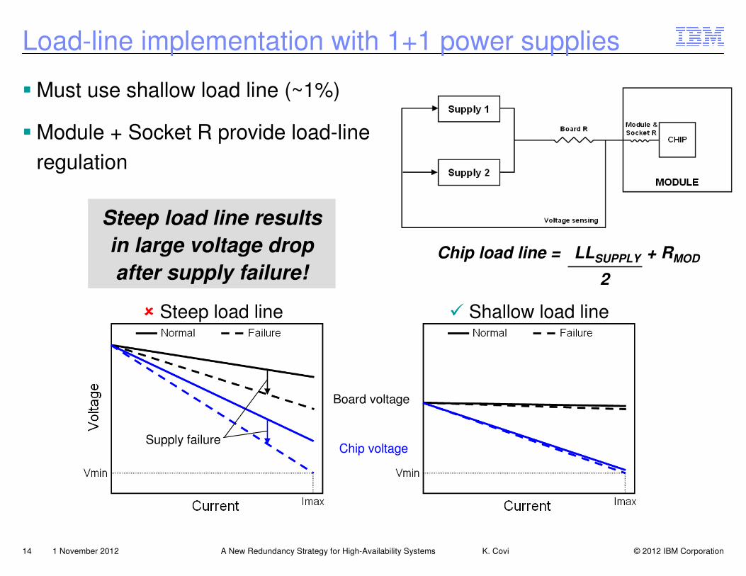
Load-line implementation with 1+1 power supplies
� Must use shallow load line (~1%)
� Module + Socket R provide load-line
regulation
� Steep load line � Shallow load line
Board voltage
Chip voltageSupply failure
Steep load line results
in large voltage drop
after supply failure!Chip load line = LLSUPPLY + RMOD
2

© 2012 IBM Corporation15 A New Redundancy Strategy for High-Availability Systems K. Covi1 November 2012
Power 6: 1+1 VRM’s
13-bitDAC
Slave
Slave
Slave
Slave
Slave
Slave
Protection
DCA 1
13-bitDAC
Slave
Slave
Slave
Slave
Slave
Slave
Protection
DCA 2
� N phases per DCA
� 1 Master per level
� 1 Protection controller per level
� Precision DAC
� Current sharing
– Initial factory calibration
– Firmware balance routine to
compensate for drift
12V
12V
Vo
Vo
Master
Master

© 2012 IBM Corporation16 A New Redundancy Strategy for High-Availability Systems K. Covi1 November 2012
Load-line regulation with N+2 power supplies
� Sense inside module at chip
� Module & Socket R is now inside
feedback loop
� Small voltage drop after supply
failure
Steep supply load lines
ensure current sharing
without precision DAC
or firmware balancing
Chip load line = LLSUPPLY
N+2

© 2012 IBM Corporation17 A New Redundancy Strategy for High-Availability Systems K. Covi1 November 2012
Current sharing with N+2 redundant regulators
� Current sharing depends on setpoint
tolerance and load-line slope
� Setpoint tolerance: VREF ~ 0.5%
� Load line slopes:
• Steep: ~10% when sensing on chip (Vcore)
• Shallow: ~2% when sensing on board
(memory, I/O, etc.)
� Current sharing error for 35A Slave
• 25% with 2% LL � ±8.75A per phase
• 5% with 10% LL � ±1.75A per phase
Comparison with N+1=2:
∆∆∆∆I = 50% of rated load(1% load line)

© 2012 IBM Corporation18 A New Redundancy Strategy for High-Availability Systems K. Covi1 November 2012
N+2 Master-per-Slave POL converter
Protection
Master
Slave
Protection
Master
Slave
Protection
Master
Slave
Protection
Master
Slave
Protection
Master
Slave
Protection
Master
Slave
Protection
Master
Slave
Protection
Master
Slave
� N+2 phases per POL card
� N+2 Masters
� N+2 Protection controllers
– Originally developed for
Phase Redundant VRMs in
IBM Power 780 Server
� Current sharing
– Uses internal DAC
– No calibration
– No firmware balancing
12V Vo
POL card(concept)

© 2012 IBM Corporation19 A New Redundancy Strategy for High-Availability Systems K. Covi1 November 2012
POL card with redundant I2C multiplexer
Protection
Master
Slave
Protection
Master
Slave
Protection
Master
Slave
Protection
Master
Slave
Protection
Master
Slave
Protection
Master
Slave
Protection
Master
Slave
Protection
Master
Slave
VoI2C
MUX
I2CMUX
12VDCA 1
DCA 2
� Each DCA communicates over
independent bus
� Tolerates Master or I2C faults
� Replace after 2nd failure
– MUX is not critical for power
conversion

© 2012 IBM Corporation20 A New Redundancy Strategy for High-Availability Systems K. Covi1 November 2012
Redundancy overhead comparison
0%
20%
40%
60%
80%
100%
1+1 P795 P795 with
proposed
architecture
130A per phase
35A per phase

© 2012 IBM Corporation21 A New Redundancy Strategy for High-Availability Systems K. Covi1 November 2012
Summary of proposed architecture
�Disadvantages
– Higher voltage ripple (no clock sync)
– Needs a load line for current sharing
– Multiple masters complicate SVID communication
�Advantages
– Fault tolerant power conversion, controls and telemetry
– Fail-in-place RAS (replace only after 2nd failure)
– Works with any VRM chipset (w/serial interface)
– No firmware current balancing
– Improved DCA reliability (12V bulk + low-current levels only)
– Low redundancy overhead

© 2012 IBM Corporation22 A New Redundancy Strategy for High-Availability Systems K. Covi1 November 2012
Thank you!