a process mapping procedure for … pennsylvania state university the graduate school department of...
TRANSCRIPT

The Pennsylvania State University
The Graduate School
Department of Architectural Engineering
A PROCESS MAPPING PROCEDURE FOR PLANNING BUILDING INFORMATION
MODELING (BIM) EXECUTION ON A BUILDING CONSTRUCTION PROJECT
A Thesis in
Architectural Engineering
by
Chitwan Saluja
2009 Chitwan Saluja
Submitted in Partial Fulfillment of the Requirements
for the Degree of
Master of Science
December 2009

The thesis of Chitwan Saluja was reviewed and approved* by the following:
John I. Messner Associate Professor of Architectural Engineering Thesis Advisor Chimay J. Anumba Head of the Department of Architectural Engineering and Professor of AE M. Kevin Parfitt Associate Professor of Architectural Engineering
*Signatures are on file in the Graduate School

iii
ABSTRACT
The implementation of Building Information Modeling (BIM) in the Architecture,
Engineering and Construction Industry is still in its formative stages. Project organizations
frequently struggle with the development of a comprehensive BIM implementation strategy
which considers process integration along with information interoperability throughout the
lifecycle of a project. To successfully implement BIM on a project, it is critical for the project
team to perform detailed and comprehensive planning.
This research establishes a Process Mapping Procedure for planning BIM implementation
on a project. This Procedure provides an opportunity for the project team to map the
implementation process for the various uses of BIM on a project. By mapping the detailed
process, key information exchanges can be identified, and a method for documenting and
planning these information exchanges is presented.
The process maps aim to specifically address which organizations will be using BIM on
the project, what will they be performing with BIM applications, and how will they share
information between the primary BIM Uses. Each project team member should develop detailed
process maps for each BIM Use. Additionally, an information exchange documentation method
was created to assist project teams in the accurate definition of key BIM deliverables. Information
elements included in this method include information delivery schedule, responsible party, and
information content for the BIM deliverables. A procedure has been documented to assist in the
completion of process maps and information exchange worksheet.
The BIM Process Mapping Procedure was validated through the creation of template
process maps, quasi-experiments, and a case study assessment. The survey results from the quasi-
experiments show that the Procedure was adequately detailed to create process maps. The focus
group discussion following the case study indicated a comprehensive Procedure. Overall, the

iv
BIM Process Mapping Procedure can increase the level of planning for a project by familiarizing
the team with the strategies and processes of their team members to achieve a more informed and
effective transition of information between responsible parties.

v
TABLE OF CONTENTS
LIST OF FIGURES ................................................................................................................. x
LIST OF TABLES ................................................................................................................... xiv
ACKNOWLEDGEMENTS ..................................................................................................... xv
Chapter 1 Introduction to the Research................................................................................... 1
1.1 Project Execution Planning Procedure for Building Information Modeling .............. 1
1.2 BIM Project Execution Planning Procedure .............................................................. 2
1.3 Scope of Work ........................................................................................................... 4
1.4 Research Goal ............................................................................................................ 6
1.5 Research Objectives ................................................................................................... 6
1.6 Research Contributions .............................................................................................. 7
1.7 Integration of the Research Work with the NBIMS ................................................... 7
1.8 Thesis Organization ................................................................................................... 8
Chapter 2 Research Methodology ........................................................................................... 9
2.1 Research Introduction ................................................................................................ 9
2.2 Research Process ........................................................................................................ 10
2.2.1 BIM Process Mapping Procedure Definition and Development ..................... 12
2.2.2 BIM Process Mapping Procedure Assessment ................................................ 13
2.3 Research Techniques .................................................................................................. 14
2.3.1 Quasi-experiment ............................................................................................ 14
vi
2.3.2 Case Study ....................................................................................................... 16
2.4 Methods of Validating the BIM Process Mapping Procedure ................................... 17
2.5 Chapter Summary ...................................................................................................... 20
Chapter 3 Literature Review ................................................................................................... 21
3.1 The Need for BIM Process Integration ...................................................................... 21
3.2 Process Mapping ........................................................................................................ 23
3.2.1 Purpose of Process Maps ................................................................................. 24
3.2.2 Perspectives in Process Representation ........................................................... 25
3.3 Process Modeling in the Construction Industry ......................................................... 26
3.3.1 Basic Components of a Model ........................................................................ 30
3.3.2 Business Process Modeling Notation (BPMN) ............................................... 32
3.4 Exchange of Project Data ........................................................................................... 33
3.4.1 Information Delivery Manual (IDM) .............................................................. 34
3.4.2 Model View Definition (MVD) ...................................................................... 38
3.5 Execution Guide for BIM .......................................................................................... 40
3.5.1 Consensus Documents BIM Execution Plan ................................................... 40
3.5.2 AIA Document E202-2008: BIM Protocol Exhibit......................................... 41
3.5.3 BIM Roadmap by US Army Corps of Engineers ............................................ 42
3.6 Chapter Summary ...................................................................................................... 43
Chapter 4 Defining the BIM Process Mapping Procedure...................................................... 45
4.1 Designing a Process Map for a Task with BIM ......................................................... 45
4.2 Procedure to Develop Process Maps for BIM Project Execution .............................. 46
4.2.1 Key Process Mapping Elements ...................................................................... 46
vii
4.2.2 BIM Process Mapping Components................................................................ 48
4.2.3 Strategy to Develop a Process Map for a BIM Use......................................... 49
4.2.4 Planning the Information Requirements for an Activity ................................. 50
4.2.5 Process Mapping Procedure ............................................................................ 51
4.2.6 Process Mapping Representation in BPMN format ........................................ 54
4.2.7 Designing the BIM Process Map for a Project ................................................ 55
4.3 Procedure to Define the Information Exchange for BIM Project Execution ............. 58
4.3.1 IE Components ................................................................................................ 58
4.3.2 Structure of the IE ........................................................................................... 62
4.3.3 Procedure to Complete the IE Worksheet ....................................................... 62
4.4 Chapter Summary ...................................................................................................... 63
Chapter 5 Assessing the BIM Process Mapping Procedure .................................................... 65
5.1 Process Mapping Task ............................................................................................... 65
5.1.1 Quasi Experiment Design ................................................................................ 65
5.1.2 Questionnaire Design ...................................................................................... 67
5.1.3 Process Map Content Analysis ........................................................................ 68
5.2 Process Mapping Outcomes and Analysis ................................................................. 68
5.2.1 Questionnaire Survey ...................................................................................... 68
5.2.2 Process Map Analysis ..................................................................................... 73
5.3 Summary and Lessons Learned ................................................................................. 82
Chapter 6 Case Study Evaluation ........................................................................................... 84
6.1 Millennium Science Complex Project Overview ....................................................... 84
6.1.1 Project Organization ........................................................................................ 85

viii
6.1.2 MSC Project BIM goals .................................................................................. 86
6.1.3 Modeling Responsibilities ............................................................................... 86
6.1.4 Data Collection ................................................................................................ 88
6.1.5 Data Analysis .................................................................................................. 88
6.2 MSC BIM Project Execution Planning Process ......................................................... 89
6.2.1 Identify BIM Goals and Uses .......................................................................... 89
6.2.2 Design BIM Project Execution Process .......................................................... 90
6.2.3 Develop Information Exchanges ..................................................................... 91
6.2.4 Define Supporting Infrastructure for BIM Implementation ............................ 91
6.3 MSC BIM Project Execution Assessment: Focus Group ........................................... 92
Chapter 7 Conclusions ............................................................................................................ 96
7.1 Research Summary .................................................................................................... 96
7.2 Research Contribution ................................................................................................ 100
7.2.1 Value of Process Mapping and Information Exchange worksheet.................. 100
7.2.2 Guidelines for Creating Process Map and Information Exchanges ................. 100
7.2.3 Template Maps for BIM Uses ......................................................................... 101
7.2.4 Pilot Case Study for Project Execution Procedure for BIM ............................ 101
7.3 Limitations ................................................................................................................. 101
7.3.1 Template Maps Limitations ............................................................................ 101
7.3.2 Limited Case Study Applications .................................................................... 102
7.3.3 Limited Validation of the BIM Process Mapping Procedure .......................... 102
7.4 Future Work ............................................................................................................... 102
7.4.1 Additional Case Study Applications ............................................................... 103
7.4.2 Information Exchange Concept ....................................................................... 103

ix
7.5 Concluding Remarks .................................................................................................. 104
References ................................................................................................................................ 105
Appendix A Template Process Maps ...................................................................................... 111
Appendix B Template Information Exchange Worksheet ...................................................... 117
Appendix C Questionnaire Survey and Detailed Results ....................................................... 120
Appendix D Case Study Process Maps and Information Exchange Worksheet ..................... 129

x
LIST OF FIGURES
Figure 1-1: BIM Project Execution Planning Process ........................................................... 4
Figure 1-2: BIM Project Execution Planning Procedure ....................................................... 5
Figure 2-1: Research process for BIM Process Mapping Procedure development and
assessment ........................................................................................................................ 11
Figure 2-2: BIM Uses throughout a building lifecycle ............................................................ 20
Figure 3-1: Provide Facility (Sanvido et al. 1990) .................................................................. 27
Figure 3-2: IDEF0 box and arrow graphics (Sanvido et al. 1990) .......................................... 27
Figure 3-3: The Generic Design and Construction Process Protocol model (Kagioglou et
al. 2000). .......................................................................................................................... 29
Figure 3-4: Process map template for the Process Protocol (Fleming et al. 2000) ................. 30
Figure 3-5: Subtypes of the construction process entity (Bjork 1992) ................................... 31
Figure 3-6: A model of generic construction categories, showing some of their internal
relationships (Bjork 1995) ............................................................................................... 31
Figure 3-7: IDM technical architecture (Wix 2007) ............................................................... 35
Figure 3-8: PM for the business process: Electrical Engineering. .......................................... 36
Figure 3-9: Snapshot of the ER for the Electrical Model........................................................ 37

xi
Figure 3-10: IDM/MVD interoperability frame (Hietanen 2006). .......................................... 39
Figure 3-11: Model Element Table (American Institute of Architects 2008). ........................ 42
Figure 3-12: Long term strategic goals for BIM (Brucker et al. 2006). .................................. 43
Figure 4-1: Key process mapping objects ............................................................................... 47
Figure 4-2: Strategy to develop a process map for a BIM Use ............................................... 50
Figure 4-3: Planning the information requirements for an activity ......................................... 51
Figure 4-4: Process Mapping Procedure represented in BPMN format. ................................ 53
Figure 4-5: Terminology used for BIM process mapping (adopted from BPMN) ................. 54
Figure 4-6: Template process map for Programming ............................................................. 55
Figure 4-7: Information required to create a BIM Overview Map ......................................... 56
Figure 4-8: Sample BIM Overview Map ................................................................................ 57
Figure 4-9: Structure of the Information Exchange ................................................................ 62
Figure 5-1: Knowledge about the BIM task............................................................................ 69
Figure 5-2: Procedure was defined adequately ....................................................................... 70
Figure 5-3: Generating ideas for creating a process map ........................................................ 70
Figure 5-4: Creating a process map from the procedure and the template file ....................... 71
Figure 5-5: Communicate the process .................................................................................... 71

xii
Figure 5-6: Swimlanes ............................................................................................................ 72
Figure 5-7: The process map must have an end process to symbolize the end event. ............ 75
Figure 5-8: Embedded process should not be used as part of template map .......................... 76
Figure 5-9: Incorrect use of embedded process ...................................................................... 77
Figure 5-10: Incorrect use of swimlane .................................................................................. 78
Figure 5-11: The level of detail of the BIM deliverable is not appropriate ............................ 79
Figure 5-12: The reference information has to be detailed ..................................................... 79
Figure 5-13: Information flow missing ................................................................................... 80
Figure 5-14: Incorrect use of intermediate event .................................................................... 81
Figure 5-15: Incorrect use of symbols .................................................................................... 81
Figure 5-16: Incorrect use of symbols .................................................................................... 82
Figure 6-1: Image of the model of the Millennium Science Complex project (Source:
http://www.opp.psu.edu/planning-
construction/projects/Millennium_Science_Complex) .................................................... 85
Figure 6-2: MSC Project Level 1 BIM Overview Map .......................................................... 90
Figure 7-1: The BIM Execution Planning Procedure (The Computer Integrated
Construction Research Program 2009) ............................................................................ 97
Figure 7-2: Overview BIM Use Map ...................................................................................... 98

xiii
Figure 7-3: Portion of the Information Exchange Worksheet ................................................. 99
Figure 7-4: Information Exchange concept ............................................................................ 104

xiv
LIST OF TABLES
Table 4-1: Legend for Information Content ............................................................................ 60
Table 6-1: Modeling Responsibilities for the MSC Project.................................................... 87
Table 6-2: Identify BIM Uses ................................................................................................. 89
Table B-1: Legend for Information Content ........................................................................... 117
Table B-2: Legend for Responsible Party ............................................................................... 117
Table D-1: Legend for Information Content used for the Case Study .................................... 135
Table D-2: Legend for Responsible Party used for the Case Study ........................................ 135

xv
ACKNOWLEDGEMENTS
This work would have never been completed without the support of many great
colleagues and friends. I would like to express my deep and sincere gratitude to my advisor, Dr.
John Messner. His deep knowledge, stimulating suggestions, and compassion have been of great
value to me. His encouragement and unflinching support has provided strong motivation for all
the time put into my research and writing this thesis.
I want to sincerely thank Dr. Chimay Anumba for all the guidance not only towards my
research but towards all academic and career matters. I would also like to thank Prof. Parfitt for
showing great enthusiasm in my research and providing valuable suggestions.
This research would not have been possible without the friendship and constant
motivation and inspiration from the BIM Execution Planning and CIC Research Group team
members. Thanks are also extended to the array of people who provided support through
participation in the research activities.
This thesis is a part of the buildingSMART alliance project titled Project Execution
Planning for Building Information Modeling, focused on the acceleration of the adoption of BIM.
Many thanks to the Charles Pankow Foundation, the Construction Industry Institute (CII), the
Partnership for Achieving Construction Excellence (PACE), and the Office of Physical Plant at
the Pennsylvania State University for their interest in funding this research.

Chapter 1
Introduction to the Research
The implementation of Building Information Modeling (BIM) in the Architecture,
Engineering and Construction (AEC) industry is still in its formative stages. Today, project
organizations suffer from the incompatibilities between information content and the data formats
created by different stakeholders. Practitioners have reported that incompatibilities arise when
users deploy different versions or apply different configurations of the same software. More
importantly, the selection of a single software platform does not resolve the question of the
required Building Information Model content. Additionally, in order to achieve the goal of
interoperability, there is a need to define what information should be transferred, to whom and
when. There is also a need to develop new methods to integrate processes which are facilitated by
the use of BIM. The challenge thus lies in availing the widespread use of BIM to the extent
possible and economical, which is deepened by the lack of a consistent BIM implementation
procedure.
1.1 Project Execution Planning Procedure for Building Information Modeling
The last several years have seen a tremendous change in the awareness of architects,
contractors and owners to factors beyond construction cost and 3D coordination (Hartmann and
Fischer 2008). BIM has greatly impacted the industry as it enables better collaboration and
information sharing (Gallaher et al. 2004), and reduces the time of construction (Suermann and
Issa 2007). The eConstruction Roundtable held at New Orleans 2007 established that the owner
community has begun to realize the potential of BIM to better manage projects with the

2
objectives of reducing the life cycle cost and improving the overall quality of a facility (Hartmann
and Fischer 2008).
Despite this vision, few project teams have been able to utilize the benefits of BIM to
their fullest extent. It was further commented that some of the obstacles in achieving this have
been the lack of knowledge in implementing BIM and the current project delivery process. A
potential solution to this would be to provide the project team with a project execution plan for
implementing BIM throughout the various stages of the project life cycle. Thus the, Project
Execution Planning Procedure for Building Information Modeling would benefit both the facility
owners and project team members.
1.2 BIM Project Execution Planning Procedure
The development of BIM is flourishing, yet there are some problems in the way it is
implemented. These problems are primarily related to a lack of sharing of information between
lifecycle phases since many practitioners are still focused on their phase(s) of the project and fail
to recognize their stewardship role in the overall lifecycle of the facility. In order for BIM to be
fully implemented and its potential fully realized, it must allow for the flow of information from
one phase to the next, from inception onward (National Institute of Building Sciences 2007). This
can only be achieved effectively through open standards, such as the Industry Foundation Classes
(IFCs) for exchanging building information. However, direct use of IFCs alone is not possible. It
is also important to note, that the decision of implementing BIM on a project is often dependent
on the project characteristics, the parties involved, commitments, situations and challenges on a
project or within the company. Agreements among stakeholder representatives must be created to
define what specific information is to be provided by whom, to whom, and when.

3
The BIM Project Execution Procedure (BIM Plan) outlines a four step method to develop
a detailed implementation plan. The procedure was designed to guide owners, program managers,
and early project participants through a structured process to develop detailed and consistent
plans for projects. A goal of the BIM Plan is to steer the project team in making the
implementation decisions early on, and to assist in a smooth transition between various parties
involved during the different project phases. In doing so, it is critical that the BIM Plan is not
developed in isolation. No one party within a construction project can adequately outline the
execution plan while also obtaining the necessary team member commitments to BIM
implementation. The team must conduct a series of planning meetings to develop the execution
plan. This will make it easier for teams to accurately plan the execution strategy on a project.
If all organizations map their standard processes (refer to Figure 1-1), then the procedure
is a design task which compiles the different work processes from the various team members. It
will also make it easier for team members including the owner to quickly and effectively
understand and evaluate the execution plans since they will be organized in a standard format
with consistent information.

4
Figure 1-1: BIM Project Execution Planning Process
1.3 Scope of Work
This research is focused on a specific area within a larger research context. The larger
research project is focused on designing a method to create a BIM Plan. The BIM Project
Execution Plan is being developed as a four step Procedure1, refer to Figure 1-2:
1. Identify BIM Goals and Uses: The first step in the planning process is to clearly define
the overall goals for BIM implementation. Once the team has defined their goals then the
specific BIM uses on the project can be identified. This includes a review of BIM uses,
starting from the operations phase of the project. Several examples of BIM Uses include
design authoring, 4D Modeling, cost estimating, and record modeling. The team should
identify and prioritize the appropriate uses for BIM they would like to perform on the
project.
1 For more information, please visit the website: http://www.engr.psu.edu/ae/cic/BIMEx/

5
2. Design the BIM Execution Process: Once the team has identified the BIM Uses,
Process Maps (PM) must be created for planning the implementation of the selected uses.
This allows all team members to clearly understand how their work processes interact
with the processes performed by other team members.
3. Define the Information Exchanges: After developing the appropriate BIM PM, the
information exchanges which occur between the project participants need to be clearly
identified. The information content for the exchange can be defined in the Information
Exchange (IE) worksheet.
4. Define the Infrastructure Required to Support the Process: After identifying the BIM
Uses; defining the PMs and developing the IEs; the team can then develop a detailed
BIM Implementation Plan. It is important to include all project information relevant and
supportive to BIM. Some of these categories include communication procedures,
technology infrastructure needs, model structure and quality control procedures.
Figure 1-2: BIM Project Execution Planning Procedure
6
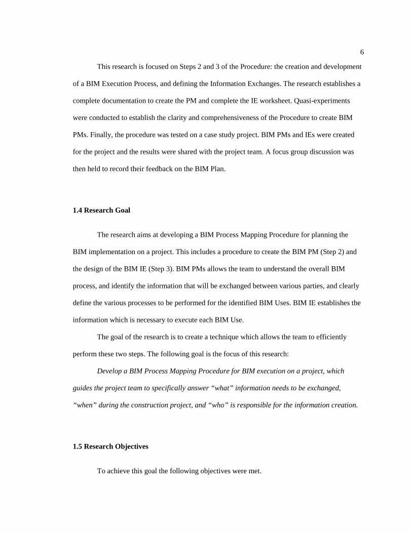
This research is focused on Steps 2 and 3 of the Procedure: the creation and development
of a BIM Execution Process, and defining the Information Exchanges. The research establishes a
complete documentation to create the PM and complete the IE worksheet. Quasi-experiments
were conducted to establish the clarity and comprehensiveness of the Procedure to create BIM
PMs. Finally, the procedure was tested on a case study project. BIM PMs and IEs were created
for the project and the results were shared with the project team. A focus group discussion was
then held to record their feedback on the BIM Plan.
1.4 Research Goal
The research aims at developing a BIM Process Mapping Procedure for planning the
BIM implementation on a project. This includes a procedure to create the BIM PM (Step 2) and
the design of the BIM IE (Step 3). BIM PMs allows the team to understand the overall BIM
process, and identify the information that will be exchanged between various parties, and clearly
define the various processes to be performed for the identified BIM Uses. BIM IE establishes the
information which is necessary to execute each BIM Use.
The goal of the research is to create a technique which allows the team to efficiently
perform these two steps. The following goal is the focus of this research:
Develop a BIM Process Mapping Procedure for BIM execution on a project, which
guides the project team to specifically answer “what” information needs to be exchanged,
“when” during the construction project, and “who” is responsible for the information creation.
1.5 Research Objectives
To achieve this goal the following objectives were met.

7
1. Develop a BIM Process Mapping Procedure: A procedure is developed which gives step-
by-step instructions on how to create a BIM PM and IE. This procedure provides
complete directions on how to quickly create a PM and fill out the IE worksheet.
2. Validate the BIM Process Mapping Procedure: Once the procedure to create PMs and
IEs was established, it was necessary to validate it. To accomplish this task, quasi-
experiments, template maps, and a case study validation were completed.
1.6 Research Contributions
The contributions of this research are:
• Documentation of the development and definition of a BIM Process Mapping
Procedure for planning the implementation of BIM on a project;
• Template PMs for five BIM Uses on a project. These Template Maps can be used by
the project teams for the creation of project specific PMs; and
• Documentation of the BIM Execution Plan on a case study project.
1.7 Integration of the Research Work with the NBIMS
The National Building Information Modeling Standard™ (NBIMS) is currently being
developed by the buildingSMART alliance™, the North American Chapter of the
buildingSMART International Ltd. The goal of the NBIMS is to identify and define standard IEs
that are required on facility projects. The BIM Plan Procedure is designed to complement the
standard exchange requirements under development in the NBIMS initiative. It will also make it
easier for team members including the owner to quickly and effectively understand and evaluate

8
the developed execution plans because they will be organized in a standard format with consistent
information.
1.8 Thesis Organization
This Chapter identified the goals, objectives and contributions of this research effort. The
scope of work along with the BIM Project Execution Planning Procedure was also presented. The
steps which were followed to complete this research are listed and elaborated in Chapter 2. The
various techniques employed during the research to obtain valuable data related to the BIM
Process Mapping Procedure is also discussed in Chapter 2. Chapter 3 provides an overview of the
literature and establishes the background of this study. The procedure to develop the PM along
with the process mapping components and the representation in the Business Process Modeling
Notation is discussed in Chapter 4. Chapter 4 also discusses the structure of the IE worksheet, its
components and a workable procedure to complete the worksheet. In Chapter 5, the results of the
quasi-experiments conducted are produced along with the results of the questionnaire survey and
lessons learned from the content analysis of the maps. Chapter 6 discusses the case study
evaluation of the BIM Ex Procedure and the results of the focus group discussion. Finally, in
Chapter 7, the conclusions of this research are discussed along with suggestions for future work.

Chapter 2
Research Methodology
Sections 1 and 2 of this chapter introduce the research and then discuss the research
process, in chronological order, which will be adopted for this study. The third section of the
chapter describes the different research techniques adopted to achieve the research goals and
objectives.
2.1 Research Introduction
Many researchers and practitioners have documented that BIM is a new approach in
sharing and communicating the required information for the design, construction and operation of
facilities (Eastman et al. 2008; Jernigan 2007; Smith and Tardiff 2009). It is moving the industry
from traditional paper based communications towards an integrated process in which the tasks
have been collapsed into a collaborative process that maximizes web communication and
computing capabilities into information capture (National Institute of Building Sciences 2007).
However, to use BIM effectively, the quality of communication between different participants
and tasks in the construction industry needs significant improvement, which lays the premise for
the research. To make the information exchange between project participants more reliable and
improve information quality, there is an urgent need to address the evolution of information for
important BIM related processes throughout the project life cycle. Many BIM processes and
applications have been discussed through single case studies, and white papers provided by
specific vendors (Autodesk White Paper 2002; Bentley and Workman 2003; Eastman et al. 2008;
Leicht and Messner 2008; Messner and Lynch 2002; Smith and Tardiff 2009; Staub-French and
Khanzode 2007). Though it is fascinating to learn about the cases and anecdotes, it is important to

10
develop an implementation procedure in the form of a process flow that has a common structure
which is applicable across many projects.
2.2 Research Process
This study utilizes qualitative and quantitative research methods performed through
literature review, surveys and case study evaluations for developing and assessing the Process
Maps (PMs) and Information Exchanges (IEs) for BIM Project Execution. The following steps
define the research process adopted to accomplish the objectives of the study, (see Figure 2-1).

11
RESEARCH PROCESS
Review literature
Develop a framework for a BIM Process Mapping Procedure
Perform pilot quasi-experiments with two undergraduate students
Detail the BIM Process Mapping Procedure using the framework developed
a) Creation of template process maps
b) Quasi-experiments
Refine the BIM Process Mapping Procedure
Proc
edur
e D
evel
opm
ent
Proc
edur
e A
sses
smen
t
Figure 2-1: Research process for BIM Process Mapping Procedure development and assessment
Validation of the Process Mapping Procedure through
c) Case Study Evaluation

12
2.2.1 BIM Process Mapping Procedure Definition and Development
Literature was reviewed for information on the use of process mapping and the several
different models of process modeling in the construction industry. Additionally, literature was
reviewed in the areas of advancements in the exchange of building product data, and several types
of BIM execution plans currently being implemented in the building industry. A summary of this
literature is presented in Chapter 3.
Following the literature review, relevant BIM Process Mapping Procedure components
were defined. First, components for the PM were developed (activity, resource, result and agent).
Next, a strategy was established to develop the Procedure to create a PM. This strategy led to the
definition of the Process Mapping Procedure steps. These steps were then represented using the
Building Process Modeling Notation (BPMN) framework, which was selected as the modeling
methodology to represent the Template PMs. On a separate track, the components identified for
IE (model element breakdown, information content, and responsible party) were developed to
define the BIM deliverables. The outcome of this step is a preliminary definition of the BIM
Process Mapping Procedure; documentation is reported in Chapter 4.
Two pilot quasi-experiments were conducted to further refine the Process Mapping
Procedure steps. Two undergraduate students from the Department of Architectural Engineering
at Penn State as part of their undergraduate work developed a PM for 3D MEP Coordination and
4D Modeling using the developed Process Mapping Procedure. The steps and the BPMN
representation of the Procedure were consistently refined over a period of two months in response
to the feedback received. The revisions were aimed in making the Procedure easily
understandable and providing clear and concise instructions to develop a PM.
13
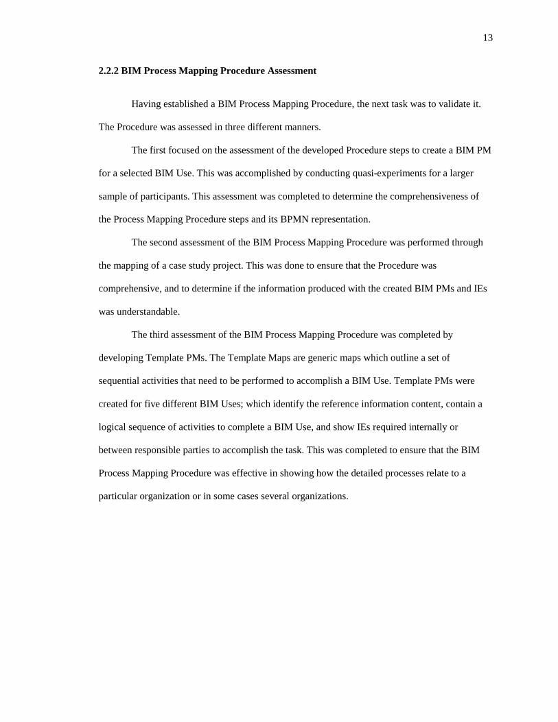
2.2.2 BIM Process Mapping Procedure Assessment
Having established a BIM Process Mapping Procedure, the next task was to validate it.
The Procedure was assessed in three different manners.
The first focused on the assessment of the developed Procedure steps to create a BIM PM
for a selected BIM Use. This was accomplished by conducting quasi-experiments for a larger
sample of participants. This assessment was completed to determine the comprehensiveness of
the Process Mapping Procedure steps and its BPMN representation.
The second assessment of the BIM Process Mapping Procedure was performed through
the mapping of a case study project. This was done to ensure that the Procedure was
comprehensive, and to determine if the information produced with the created BIM PMs and IEs
was understandable.
The third assessment of the BIM Process Mapping Procedure was completed by
developing Template PMs. The Template Maps are generic maps which outline a set of
sequential activities that need to be performed to accomplish a BIM Use. Template PMs were
created for five different BIM Uses; which identify the reference information content, contain a
logical sequence of activities to complete a BIM Use, and show IEs required internally or
between responsible parties to accomplish the task. This was completed to ensure that the BIM
Process Mapping Procedure was effective in showing how the detailed processes relate to a
particular organization or in some cases several organizations.

14
2.3 Research Techniques
2.3.1 Quasi-experiment
Cook and Campbell (1979) pointed out that quasi-experiments are “experiments that have
treatments, outcome measures, and experimental units like true experiments; but do not use
random assignment to create comparative studies.” The term quasi-experiments is used in
situations in which the experimenter cannot randomly assign subjects to experimental groups, but
the performance can still be manipulated through a set of metrics (Corbetta 2003).
For this study, the task for the participants was to create a BIM Use PM. These BIM Uses
were not randomly assigned. The PM created at the completion of the task was studied and the
observed deviations were documented as part of content analysis.
2.3.1.1 Data Collection: Questionnaire
Data for the quasi-experiment was primarily collected through a questionnaire. The
questionnaire is a widely used and useful instrument for collecting survey information; providing
structured, often numerical data, and often being comparatively straightforward to analyze
(Cohen et al. 2007). There are several kinds of questionnaire items, including, dichotomous
questions, multiple choice questions, rating scales, constant sum questions, ratio data and open
ended questions (Cohen et al. 2007). In general closed questions, e.g. multiple choice and rating
scales are quick to complete and simple to analyze. On the other hand, these questions do not
enable respondents to add remarks, qualifications and explanations to the categories, and there is
a risk that the categories might not be exhaustive and may be biased (Oppenheim 1992). Open
questions, however, enable participants to write a free account in their own terms and avoid the
limitations of pre-set categories (Cohen et al. 2007).
15
A rating scale is a closed type of questionnaire, widely used in research, combining the
opportunity for a flexible response with the ability to determine frequencies, correlations and
other forms of quantitative analysis. Cohen et al. (2007) argues that though rating scales are
powerful and useful in research, it is important to be aware of their limitations.
For this study, at the end of the quasi-experiment, the participants were asked to complete
a questionnaire survey with rating scale type questions to gain insight on the ease of creating a
PMs using the Process Mapping Procedure, and if this Procedure assisted in the generation of
additional ideas. Another section of open ended questions was also added which mainly asked for
feedback related to the Procedure or additional instructions to improve the Procedure to which the
respondents could reply in their own terms and opinion.
2.3.1.2 Content Analysis
Krippendorff (2004) defines content analysis as a research technique for making
replicable and valid inferences from texts or other meaningful matter to the contexts of their use.
As a research technique, content analysis provides new insights, increasing the researcher’s
understanding of a particular phenomenon. Krippendorff (2004) further elaborates that every text
requires a context on which it will be examined.
For this study, the PMs produced by the participants at the end of the quasi-experiment
were analyzed. All the participants created a PM for their chosen BIM use using the Procedure
steps in a BPMN application. The objective of the content analysis, as applied in this study, was
to verify if the Procedure steps were or were not followed by the participants. Additionally, with
careful scrutiny, the researcher documented the irregularities observed in the produced PMs (refer
to Chapter 5), and redefined the Procedure to more clearly define the topic in an attempt to
address most of these observed irregularities.

16
2.3.2 Case Study
Yin (2003) points out that the case study method has been a common research
methodology, used on many situations, ‘to contribute to the knowledge of individual, group,
organizational, social, political, social and related phenomena’. Yin (2003) further suggests that
the case study research is very useful where (1) the research question typically answers to ‘how’
or ‘why’, (2) the investigator has a little/no possibility to control the events, and (3) the focus of
the study is contemporary phenomenon in a real-life context. In this study, the research question
addresses ‘how’ projects can utilize BIM Process Mapping Procedure. Also, since the real world
decisions of BIM implementation for the case study project is discussed, the researcher did not
have much control over the variables of investigation.
Case studies typically combine data collection methods such as archives, interviews,
questionnaires, and observations. The evidence may be qualitative (e.g., words), quantitative
(e.g., numbers) or both (Eisenhardt 1989).
Finally, case studies can be used to accomplish various aims: to provide description, and
to test or generate theory (Eisenhardt 1989). The interest here is in the second aim of testing a
theory. The goal of the case study was to use historical mapping technique to validate the BIM
Project Mapping Procedure.
2.3.2.1 Data Collection for the Case Study Project
Yin (2003) identifies six sources of evidence that can be collected during case studies:
• Documents;
• Archival records;
• Interviews;
• Direct observations;

17
• Participant observation; and
• Physical artifacts.
For this study, evidence was collected via document access and direct observations. Yin
(2003) recommends “documentation as stable evidence because it can be reviewed repeatedly, it
is unobtrusive, it is exact and it has a broad coverage.” However, it can also be “difficult to
retrieve; the selection and reporting can be biased; and the access can deliberately be blocked.”
On the other hand; “direct observations have the advantage of being real-time and contextual, but
they can be time consuming, selective, the observed event may react different due to the
observation, and is time consuming.”
The researcher attended several (about ten) of the weekly design coordination meetings
starting from the BIM coordination kickoff meeting. The BIM Coordinator for the case study
project also made the necessary documentation available throughout the course of the study.
2.3.2.2 Data Analysis for the Case Study Project
Data analysis in case study research consists of three concurrent flows of action: data
reduction, data display, and conclusions and verification (Miles and Huberman 1994). For this
study, the collected data was methodologically analyzed and linked to the BIM Process Mapping
Procedure to produce a set of PMs and corresponding IEs. The documentation produced for the
case study was later approved by the Project Manager and the BIM Coordinator for interpretation
and accuracy.
2.4 Methods of Validating the BIM Process Mapping Procedure
During the course of this study, three methods were adopted to validate the BIM Process
Mapping Procedure:

18
1) Quasi-experiments: To ensure if the Procedure steps and the BPMN representation of
the Process Mapping Procedure were self explanatory, quasi-experiments were conducted
with eleven graduate students from the Department of Architecture and Architectural
Engineering at The Penn State University. Before conducting the quasi-experiments, a
pilot study was performed with two undergraduate students at the Department of
Architectural Engineering. Using the Process Mapping Procedure and the BPMN
representation of the framework, these two students created Template PMs for 3D MEP
Coordination and 4D Modeling BIM use, as a requirement of their thesis work. The
piloting of the quasi-experiments was done in an attempt to create a consistent and
understandable Procedure and the BPMN representation. During the quasi-experiments,
all the participants were made familiar with the process modeling notation adopted to
create PMs. A post experiment survey was conducted to get feedback on the Process
Mapping Procedure. The quasi-experiment was done to ensure that the Process Mapping
Procedure could be followed and understood to create a PM. The deviations in the PMs
produced were documented as part of the content analysis and relevant changes were
made to the Procedure to address these challenges. Documentation on quasi-experiment
design, process map outcome and analysis and the survey results is in Chapter 5.
2) Case study evaluation: BIM PMs and IEs were created for the selected BIM Uses for
the case study project. The aim here was to validate the BIM Plan Procedure and create a
BIM implementation plan for a project team addressing the relevant BIM factors. The
scope of the thesis research is to document Step 2 and Step 3 of the BIM Plan Procedure.
The information for the case study project was received on a first hand basis by having
informal discussions with BIM Coordinator on the project. The PMs and the IEs created
for the case study evaluation was finally reviewed and approved by the Project Manager
and BIM Coordinator on the project for accuracy. It was also necessary for the study to
capture the communication value and effectiveness of the created BIM PMs and IEs. This

19
was accomplished by conducting a focus group meeting with the key project team
members to discuss the created BIM Execution plan, any issues related to it, and to
determine future scope of improvement. The details of the case study evaluation have
been documented in Chapter 6.
3) Template Process Maps: The third assessment of the BIM Process Mapping Procedure
was done by developing Template PMs for five BIM Uses. The Template Maps are
generic maps which outline a set of sequential activities that need to be done in order to
accomplish a BIM Use. It is realized that there could be many different ways of
accomplishing a BIM Use. A generic map can be used to create a more detailed map
based on the project requirements and chosen software application. For example, a
Quantity Takeoff task includes the following three activities: export BIM for analysis,
calculate quantities, and review quantities. Template PMs with this level of detail were
created for five different BIM Uses, identifying the reference information content, a
logical sequence of activities to complete a BIM Use, and IEs required internally or
between responsible parties to accomplish the task. These BIM Uses were chosen from
each of the building lifecycle phases, i.e. Plan, Design, Construct, and Operate. One BIM
Use was chosen from a multiphase use which spans in multiple phases. Refer to Figure
2.2 for the list of identified BIM Uses. This was done to ensure that the BIM Process
Mapping Procedure can be used for a variety of tasks and scenarios across the lifecycle of
a project. In accordance with these criteria, Template PMs have been created for the
following BIM Uses: Programming (Plan), Energy Analysis (Design), 3D Coordination
(Construct), Record Modeling (Operate) and Cost Estimation (Multiphase). The
Template PMs have been included in Appendix A.

20
Figure 2-2: BIM Uses throughout a building lifecycle
2.5 Chapter Summary
This Chapter presented the research process and techniques that the researcher had
employed to define, develop and assess the BIM Process Mapping Procedure. The premise for the
research is the lack of a common implementation strategy across various organizations and
information interoperability. The goal for developing this structured planning procedure is to
stimulate and direct communication and planning by the team in the early phases of a project.
While there is no single best method for BIM implementation on every project, each team must
effectively design a tailored execution strategy by understanding the project goals and
characteristics. Once the BIM Process Mapping Procedure was developed, it was necessary to
validate the research through various techniques. Quasi-experiments, development of Template
PMs, and the implementation of the Procedure on a case study project were adopted for the
assessment and evaluation of the BIM Process Mapping Procedure.

Chapter 3
Literature Review
To develop a BIM Process Mapping Procedure, it was necessary to look at the current
efforts on BIM implementation in the industry. It was important to review the existing literature
in several domains: the intra-organizational aspect of BIM and how organizations utilize this
technology within the company; the future potential of BIM and where the industry is heading;
and the inter-organizational use of BIM. The literature establishes the need for BIM process
integration to address the challenges of the inter-organizational use of BIM; and also identifies
the current efforts by the NBIMS to establish the exchange of product data.
3.1 The Need for BIM Process Integration
The need to transfer data between engineering applications has existed before the
development of the first CAD systems. It arises due to the collaborative nature of design. While
the non –BIM environment does not facilitate efficient transfer of information during the critical
phases of the facilities lifecycle (Eastman et al. 2008; Teicholz 2004) , the utilization of BIM
technology requires dramatic changes in the current business practices (Derrick and Mei Kuen
2008; Mihindu and Arayici 2008; Sidwell 1990). The acceptance of BIM has been a challenge
requiring a steep learning curve and a paradigm shift in the business models of Architecture
Engineering Construction/ Facility Management (AEC/FM) organizations. Laiserin (2007) has
pointed out some potential areas of improvement:
• Accuracy: Complete, correct communication between AEC/FM project participants;
for example, owner requirements to designer (program/brief), designer feedback to

22
owner (visualization/simulation), design intent to construction documents (CDs), and
CDs to constructors/bidders;
• Consistency: Uniformity within a representation; for example, within a set of
drawings or specs;
• Integration: Linkage between related representations; for example, between
drawings and specifications or between models and sequencing/schedules;
• Coordination: Interference checking among disciplines; for example, between
building and site or between structural and mechanical/electrical/plumbing (MEP);
• Synchronization: Achieving comparable levels of detail/resolution over time; for
example, drawings/specifications versus cost.
Additionally, several researchers have recognized the problems caused by the
fragmentation of the industry (National Institute of Building Sciences 2007); and the lost
opportunity costs caused by inadequate interoperability (Gallaher et al. 2004); and inconsistent
technology adoption among stakeholders (Wix 2007).
Fox and Hietanen (2007) have reported several challenges to the inter-organizational use
of BIM including: management challenges; shortcomings of IFC; lack of cross trained staff with
both construction and IT skills; archiving of information; and multiple design perspectives.
Architects tend to perceive buildings as systems of spaces, while HVAC engineers see buildings
as systems of thermal zones is just one example of the multiple design perspectives. Therefore,
the creation of a model is fit for the purposes of several different types of analyses throughout the
building lifecycle. As a result, the transition between multiple parties requires a lot of thought and
execution (Fox and Hietanen 2007).
Fox and Hietanen (2007) have also reported the results of interviews from several
organizations regarding the existing and planned use of BIM. A number of participants mentioned
‘inconsistencies in the ways in which BIM models were being created’ as a major technological

23
challenge that they faced. Some individuals had the opinion that these inconsistencies can be
overcome by establishing inter-organizational guidelines for the creation of BIM models. This
establishes a need to create standardized information exchanges (IEs) that are required to define
facility projects.
The latest effort is the development of an integrated building model supports data
exchange using the Industry Foundation Classes (IFC) of the International Alliance of
Interoperability (IAI) (Eastman 1999). The intent of the IAI, now functioning under a new brand
called buildingSMART, is to provide means of passing a complete and accurate BIM model from
the computer application used by one party to computer application used by other parties without
any loss of information (IAI 2008). To maintain industry enthusiasm for the benefits of
integration, the IAI has sought to define and release a new version of the IFC every year,
encouraging quick and incremental development (Eastman 1999).
Eastman (1999) has argued that as ‘the general flow of work has become more
distributed, the tacit process knowledge embedded in the workflow needs to become more
explicit.’ This is due to the fact that the process operating on some data and the data exchange
carrying that information are interdependent. This justifies a need for not only a standard and
consistent data exchange, but also, a detailed and parallel commitment of defining and modeling
processes supporting the data exchange.
3.2 Process Mapping
Process maps (PMs) are a visual aid for organizing work processes with links between
inputs, outputs, and tasks (buildingSMART International Ltd. 2008). It describes the flow of
activities within the boundary of a particular topic. The concept of process, however, lacks a

24
commonly agreed definition. A typical definition for process is: a set of partially ordered steps
intended to reach a goal (Feiler and Humphrey 1992).
• A process map is used to understand (buildingSMART International Ltd. 2008):
• The tasks (activities) performed within a business process,
• The sequence in which they are carried out,
• The actors (people/organizations) involved in the process, and
• The information that is exchanged between actors as a result of activity completion.
3.2.1 Purpose of Process Maps
The purpose of a process map is to assist in understanding how work is undertaken in
achieving a well defined objective (Wix 2007). A process map usually:
• Has a goal;
• Has specific inputs (typically from other exchange requirements and from other data
sources);
• Has specific outputs (typically to other exchange requirements);
• Uses resources;
• Has a number of activities that are performed in some order;
• May affect more than one organizational unit; and
• Creates value of some kind for the customer.
For the planning process in this research, the principal roles of the process map will be to:
• Establish the logical sequence of the activities within a process;
• Identify the inputs, i.e., the Reference Information and BIM deliverables that support
the activities within the process;

25
• Establish the BIM outputs and the Information Exchanges between processes; and
• Identify the team participants or the agents responsible for a particular BIM task.
3.2.2 Perspectives in Process Representation
Curtis et al. (1992) reported that many forms of information must be integrated to
adequately describe processes. Among the forms of information that people ordinarily want to
extract from a process model are: what is going to be done; who is going to do it; when and where
will it be done; how and why will it be done; and who is dependent on it being done (Curtis et al.
1992). Four common perspectives in process representations are:
• Functional: represents what process elements are being performed, and what flows of
informational entities (e.g., data, artifacts, products) are relevant to these elements. In
this view processes consist of activities that together achieve the goal. In addition,
supplementary concepts such as data exchanges can enhance the process
representation;
• Behavioral: represents when process elements are performed and how they are
performed through feedback loops, iteration, decision- making conditions, entry and
exit criteria, etc.;
• Organizational: represents where and by whom (which agents) process elements are
performed, the physical communication mechanisms used for transfer of entities, and
the physical media and locations used for storing entities;
• Informational: represents the informational entities produced or manipulated by a
process; these entities include data, artifacts, products (intermediate and end), and
objects; this perspective includes both the structure of informational entities and the
relationships among them.

26
Hypothetically, a combination of all these perspectives would provide a relatively
complete process. In the current practice of process modeling, however, the functional
perspective is most often used (Cutting-Decelle et al. 2000) as provided by the Structured
Analysis and Design Technique (SADT) and the closely related Integrated Definition Language
(IDEF0) technique (Yusuf and Smith 1996). This is because the focus is on the modeling of
project activities in a logical and causal relationship, with the activity as the basic construct and
the process concept achieves only one goal – “How to obtain the result”(Cutting-Decelle et al.
2000). Of course, this provides an area for improvement. There are three other relevant goals:
how not to consume unnecessary resources, who is responsible for the various tasks, and how to
ensure that the results correspond to the requirements.
3.3 Process Modeling in the Construction Industry
Several different types of process models have been used in the construction industry to
analyze processes. The process models relevant to the study are presented in this section. The
review presented is representative and not comprehensive, since there are many ongoing research
efforts in the field of construction process modeling.
Sanvido et al. (1990) developed the Integrated Business Process Model (IBPM) as a
generic model which establishes the processes required to provide a facility. The ‘provide
facility’ process, refer to Figure 3-1, was subdivided into managing, planning, design,
construction and operations of a facility.

27
Figure 3-1: Provide Facility (Sanvido et al. 1990)
This particular model used the IDEF0 modeling methodology and identifies the inputs,
outputs, constraints and mechanisms associated for each function. The basic concept of the
IDEF0 syntax, refer to Figure 3-2, consists of boxes and arrows with the activity represented by a
rectangular box and the flow of a process with arrows.
Figure 3-2: IDEF0 box and arrow graphics (Sanvido et al. 1990)

28
Another attempt by a research team at the University of Salford in the UK, in conjunction
with nine collaborating companies, was the Generic Design and Construction Process Protocol, or
the Process Protocol2. The Generic Design and Construction Process Protocol essentially breaks
down the design and construction process into 10 distinct phases, shown in Figure 3-3. These 10
phases are grouped into 4 broad stages, namely Pre-Project, Pre-Construction, Construction and
Post-Construction. These phases cover aspects of a project lifecycle from the demonstration and
conception of need to the operation and maintenance of the constructed and/or refurbished
facilities.
The map draws from principles developed within the manufacturing industry that include
stakeholder involvement, teamwork and feedback, and reconstructs the design and construction
teams to create multi-functional group of participants called the ‘Activity Zones’. These activity
zones are represented on the Y-axis of the process protocol and represent the structured set of
tasks and processes which guide and support work towards a common objective (Kagioglou et al.
2000).
2 For more information, visit the website: www.processprotocol.com

29
Figure 3-3: The Generic Design and Construction Process Protocol model (Kagioglou et al.
2000).
In a continued attempt by the same group, with additional expertise from Loughborough
University, the Process Protocol Level II was created. The primary deliverable was to create sub
process maps of the eight Activity Zones that exist within the original Generic Design and
Construction Process Protocol model (Fleming et al. 2000).
The Process Protocol is not mapped using a standardized format. Visio was used as a
diagramming tool and an original process map template was developed depicting the ownership
of a process, the process name, and the participants involved. This was necessary for the
successful completion of a project as shown in the Figure 3-4.

30
Figure 3-4: Process map template for the Process Protocol (Fleming et al. 2000)
None of the process maps discussed specifically focus on the tasks that a project team
must perform to effectively implement BIM on a project level. The existing models are also not
adequate for supporting the strategic decisions to be made by a construction team since an
information handover is required encompassing many specific BIM tasks, company information
and other external information. Therefore, a project specific approach is needed to assist the
project teams in successfully analyzing the strategic decisions and implementing BIM.
3.3.1 Basic Components of a Model
Several process models have been developed in the construction domain. A synthesis of
the common features of these process models as described by Bjork(1992) is based on three main
categories: activities, results, and resources. An activity uses resources to produce results.
Traditional construction classification systems often tend to equate result to building and their
parts. Other important sub-types of results are information, mostly delivered as documents, and
services.

31
The construction process entity can be divided into a number of subtypes, refer to Figure
3-5 (Bjork 1992).
Figure 3-5: Subtypes of the construction process entity (Bjork 1992)
Bjork (1995) also provided an EXPRESS-G representation of some of these objects in a
generic construction process, as shown in Figure 3-6.
Figure 3-6: A model of generic construction categories, showing some of their internal
relationships (Bjork 1995)
Activity Result
Document
Physical object
Service
Agent
Organization
Person
Machine
Facility
Resource use Cost Contract

32
3.3.2 Business Process Modeling Notation (BPMN)
A BIM Process Mapping Procedure has been developed using the BPMN modeling
methodology. The reasons for adopting this notation over other methods such as IDEF0 are:
• BPMN provides businesses with the capability of defining and understanding their
internal and external business procedures through a Business Process Diagram, which
will give organizations the ability to communicate these procedures in a standard
manner. It is a standard maintained by the Object Management Group (OMG) with a
richer set of capabilities for modeling business process than IDEF0 (buildingSMART
International Ltd. 2009);
• It has a better capability to express business process. In particular, it uses 'swimlanes'
to enable communication between actors to be visualized. This is not easy to do with
IDEF0 but is critical to seeing where exchange requirements are needed in IDM (Wix
2007);
• There are several available software tools that range from fairly simple, free benefits
to extensive industrial strength solutions. For the purpose of demonstrating the use in
this research, the TIBCO and Microsoft Visio software application will be used to
create PMs;
• The notation has a conversion method to the Business Process Execution Language
for Web Services which is emerging as a standard XML based approach for
workflow control (Wix 2007); and
• There is a possibility to better integrate with the detailed information exchange
mapping initiatives used in the IDMs currently being developed for the NBIMS as
well as BIM Standards in other countries.

33
3.4 Exchange of Project Data
The exchange of information between various project participants has always been very
important, but at the same time, a very difficult task. Recently, with considerable number of
software implementations, the Industry Foundation Classes (IFC) has turned out to be a leader in
establishing an interoperable standard for the exchange of building product information. The IFC
specifications, developed by the International Alliance of Interoperability3 (IAI), has been
promoting its vision of a STEP based integrated product model which would cover all vital
information about the building in its life cycle. The alliance aims at developing an object
oriented data model to allow different disciplines to accurately share technical information with
IFC compliant tools (International Alliance for Interoperability 2001). However, since the start of
its first industrial pilot application with the HUT-600 project (Fischer and Kam 2002), there are
still many shortcomings which undermine the reliability of data exchange (Pazlar and Turk 2008).
The shortcomings include geometric misrepresentation, loss of object information, confusion in
interdisciplinary revisions, large file size, and specific application requirements. However, as
IFC’s continue to evolve, some of these challenges have been addressed in more recent releases
of IFC (e.g., IFC 2x3).
While this approach has progressively satisfied the requirements for a complete schema;
it is not able to capture the business process and its various developments which a user may later
need (Wix 2007). Similarly, it also does not account for the ways in which information is created
and shared by the practitioners which justifies the need for Model View Definitions (MVD) and
the Information Delivery Manuals (IDM).
3 For more information on IAI visit: http://www.iai-tech.org/products/ifc_specification/
34
In spite of this development in the technology, there are several obstacles in completing
the model and consequently establishing an integrated design and construction process (Bazjanac
2002; Pazlar and Turk 2008):
• The extent of fragmentation in the AEC industry;
• Unique software products;
• Growing requirements of the AEC industry; and
• Traditional working methods.
To combat these general obstacles and complementing the above efforts, a refined
procedure for BIM Project Mapping Planning is developed in this research.
3.4.1 Information Delivery Manual (IDM)
Wix (2007) argues that the IFCs provide a comprehensive reference to the totality of
information within the lifecycle of a constructed facility, however, it does not incorporate a
comprehensive reference to the individual processes within building construction. The
Information Delivery Manual (IDM) aims to “provide the integrated reference for process and
data required by BIM by identifying the discrete processes undertaken within building
construction; the information required for their execution; and the results of that activity” (Wix
2007). It will specify:
• Where a process fits and why it is relevant;
• Who are the actors creating, consuming and benefitting from the information;
• What is the information created and consumed; and
• How the information should be supported by software solutions.

35
Figure 3-7: IDM technical architecture (Wix 2007)
The three main components of an IDM are Process Map (PM), Exchange Requirements
(ER) and Functional Parts (FP), refer to Figure 3-7. Through these components business
processes are identified, described and specified in order to meet the needs from participants in
the AEC/FM project lifecycle (buildingSMART International Ltd. 2006). Wix (2007) explains
the logical sequence of creating an IDM. Typically, it should start by defining a PM, then specify
the defined ER's and the belonging FP's.
The main goal for the PM is to (buildingSMART International Ltd. 2006):
• Identify in which project stages (e.g. outline design, full conceptual design,
coordinated design etc) of the process there are exchange of information for this
business process;

36
• Identify all the ER's for this business process. ER's can also be independent of IFC
(e.g. local/national standards, building regulations etc). This will typically be input to
the process;
• Identify the purpose of the business process and sub-processes; and
• Identify the result of execution of the processes – output.
Refer to Figure 3-8 for a sample PM for Electrical Engineering.
Figure 3-8: PM for the business process: Electrical Engineering4.
An ER is typically unique within a project stage. However in many cases the business
process has a cyclical sequence between project stages. Essentially, it is the degree of detail of
information and the decomposition of elements from speculative into more specific types that
changes from stage to stage. The main goals for ER's are to (buildingSMART International Ltd.
2006):
4 For a complete reference to the available PMs within the IDM, please refer to http://idm.buildingsmart.no/confluence/dashboard.action

37
• Identify what information a specific business process needs;
• Describes the information that must be passed from a business process to enable
another to happen;
• Identify the actors sending and receiving information within the process by role;
• Identify when information exchange must happen;
• Identify a table of information units needed to satisfy the requirement (other ER's and
FP's); and
• Specify the functional part that satisfies the information unit.
A snapshot of ER for the Electrical Model Exchange is shown in Figure 3-9.
Figure 3-9: Snapshot of the ER for the Electrical Model

38
ER's and PM's are not independent of each other. It is therefore essential that they are
coordinated to serve the complete project. The main goals of the FP's are to (buildingSMART
International Ltd. 2006):
• Describe the actions that are carried out within a business process to provide the
resulting output information;
• Be reusable or may be used by many exchange requirements;
• Ability to be broken down into other functional parts;
• Specify other functional parts that are used; and
• Identify IFC entities, attributes, property sets and properties required.
3.4.2 Model View Definition (MVD)
The MVD format was adopted by the IAI in 2005 as a format for defining views for IFC.
Software that claims to be IFC compliant is certified against these views or subsets of the
complete IFC specification (Wix 2007). The goal of MVD is to provide information for software
users about IFC based solutions, and to help software developers add meaningful IFC support to
software5.
5 For more information, refer to the MVD View Definitions Website: http://blis-project.org/IAI-MVD/

39
Figure 3-10: IDM/MVD interoperability frame (Hietanen 2006).
Figure 3-10 shows the different steps that are needed for creating IFC based interoperable
solutions. One of the main responsibilities if the IAI is to ensure that the development of MVD
and IDM occur in parallel (Hietanen 2006). The MVD format is divided into two main parts, (1)
the generic part and (2) the IFC release specific part. Both parts enable to bridge the gap between
the Exchange Requirements and the IFC specification as the business language is translated to the
IFC data structure (Weise et al. 2008).
There are a couple of view definitions that are discussed within the MVD. At the moment
the most important one is the Coordination View that is the basis for available CAD
implementations (Weise et al. 2008). The MVD format is used for new developments such as the
“Structural design to structural analysis” (www.blisproject. org/IAI-MVD).
Though the approach to standardize and create consistent information by the IAI has been
enormous, it has yet to be tested, integrated and used on a broad scale. Currently, the PM and ER
of the IDM are under development, and the software vendors and users are struggling with the
interoperability issues. The BIM Process Mapping Procedure has been created for a project team
as a standardized approach to establish a BIM plan with consistent information which can be used
on the projects today. As the information exchanges become standard throughout the industry, the

40
team can reference the standard exchanges, instead of providing a custom information exchange
requirement for a task.
3.5 Execution Guide for BIM
Several types of execution plans are currently being used in the construction industry to
implement BIM in an organization or to facilitate the adoption of BIM in the industry. The
execution guides relevant to the study are presented in this section.
3.5.1 Consensus Documents BIM Execution Plan
ConsensusDOCSTM has recently released a BIM Addendum which marks a significant
step forward in utilizing BIM as a collaborative tool. The ConsensusDOCS 301 BIM Addendum
is an industry standard document to globally address the legal uncertainties associated with
utilizing BIM. The BIM Addendum is the first addition to the ConsensusDOCS' comprehensive
catalog of contracts and forms.
Additionally, the BIM Addendum requires all project participants "meet, confer and use
their best efforts to agree upon the terms of or modifications to the BIM Execution Plan." The
BIM Execution Plan or BEP is a detailed checklist for project participants to consider as they map
out responsibilities, requirements and processes in greater detail for execution on a project (Lowe
and Muncey 2008).

41
3.5.2 AIA Document E202-2008: BIM Protocol Exhibit
AIA E202 establishes the procedures and protocols the parties agree to follow with
respect to the development and management of a Building Information Model throughout the
course of a project. E202–2008 is not a stand-alone document, but is intended to be attached as an
exhibit to an existing agreement for design services or construction on a project where the parties
intend to utilize BIM. It has been primarily written to support a project using Integrated Project
Delivery (IPD). However, it can be attached to more traditional agreements (American Institute
of Architects 2008).
There are 5 basic Levels of Development (LOD) which reflect a generic definition of
model content and, more importantly, there is a column to add the MEA’s (Model Element
Author’s) which specifies who is responsible for authoring each element of the model at each
project phase, so no major design elements are missed or left unaddressed (American Institute of
Architects 2008). The Model Elements follow the CSI UniFormat ™ II classification system to
divide the Building Information Model into component parts which defines the model progression
specification for information exchange. Figure 3-11 shows the model element table of the E202
document comprising 3 essential columns of model elements, LOD and MEA.

42
Figure 3-11: Model Element Table (American Institute of Architects 2008).
3.5.3 BIM Roadmap by US Army Corps of Engineers
The BIM Roadmap by the US Army Corps of Engineers (USACE) outlines both the
strategic and implementation plans for using BIM technology to improve USACE planning,
design, and construction processes. With the adoption of BIM, the Design-Build model
request for proposal template includes language to encourage contractors to use BIM as part
of their responses. A phased set of strategic goals was developed by USACE to derive the
greatest benefit from the industry move towards BIM while also managing technology and
business process risk (Brucker et al. 2006).

43
Figure 3-12: Long term strategic goals for BIM (Brucker et al. 2006).
This document includes the USACE strategic goals and objectives, BIM implementation
plan, BIM design team work instructions, contract language and the implementation guidance
(refer to Figure 3-12). However, the aggressive road map for the adoption of BIM has caused
much confusion and forced many firms to rethink their own BIM adoption (Edwards 2009). The
language of the roadmap claims to be “BIM neutral”; the realities, nevertheless, constrain the
required files to be fully compatible with the USACE Bentley BIM v8 Workspace (Edwards
2009). The challenge is that the USACE needs the required files to be compatible with their
chosen BIM application; but currently there is no workable translation process to convert files
from other vendor applications to this format.
3.6 Chapter Summary
Existing literature provides insights about the need for data exchange and the future
potential of BIM in the construction industry. Literature review shows that the IFC standards are
agreed and accepted by the industry and is widely implemented in software applications.
However, the certification process still has some gaps and challenges which has rendered the

44
certified software useless for practical applications of IFC. As for IDM/MVD, the standards are
still under development and are not yet ready for implementation in the industry.
Further, Fox and Hietenan (2007) have reported numerous potential barriers to the inter-
organizational use of BIM models. It is an established fact that the potential of BIM is best
utilized in an environment where all the project participants adopt and implement BIM on a
project. Fox and Hietenan (2007) have documented that one of the challenges in implementing
BIM is the inconsistency among processes which leads to variations in which BIM models are
created.
The BIM Process Mapping Procedure aims to create a standardized procedure for
planning the BIM execution on projects. It encourages the organizations to create their typical
company workflows. Each of the responsible parties can then compile these different work
processes from the various team members to evaluate the various exchanges. Once the
information exchanges are identified, custom information exchange requirements for a task can
be developed suiting the project needs and organizational capabilities.

Chapter 4
Defining the BIM Process Mapping Procedure
The first section of this chapter defines the two levels of creating a Process Map (PM).
The second section identifies a procedure to develop these PMs. This includes the PM
components, procedural steps and a process representation in BPMN. The aim of the PM is to
provide a visual representation of all the processes that make up a particular BIM use. The third
section of this chapter defines a procedure to create the Information Exchange (IE) worksheet
identified in the process design.
4.1 Designing a Process Map for a Task with BIM
The creation of a BIM PM allows the team to understand the overall BIM process,
identify the IEs that will be shared between various parties, and clearly define the various
processes to be performed for the identified BIM Uses. This is accomplished by creating PMs
using BPMN. The PMs also serve as the basis for identifying other important implementation
topics including contract structure, BIM deliverable requirements, information technology
infrastructure, and selection criteria for future team members.
The BIM Process Mapping Procedure includes the creation of PMs on two different
levels:
Level 1: BIM Overview Map
A high level Overview PM should be created to show the relationship of BIM uses which
will be employed on the project. This PM shows the information flow throughout the project

46
lifecycle. This emphasizes that the BIM model attained after implementing a BIM Use will be
shared with the future BIM Uses in the succeeding phases.
Level 2: Detailed BIM Use Process Maps
Detailed BIM Use PMs are created for each identified BIM Use on the project to clearly
define the sequence of various activities to be performed. These maps should also identify the
responsible parties for each activity, reference information content, and the IEs which will be
created and shared with future processes.
4.2 Procedure to Develop Process Maps for BIM Project Execution
For a team to develop a Detailed BIM Use Map, template maps have been created which
will provide a starting point for the team and aid in identifying discussion areas. This section
identifies the process mapping components and a strategy to develop them. The methodology
notation used to develop these maps is called Business Process Modeling Notation (BPMN). A
brief introduction of BPMN is contained in Chapter 3.
4.2.1 Key Process Mapping Elements
The key elements used to define BIM Process Mapping Procedure (adopted from BPMN)
are:
• Pool: This acts as a container of all processes. It represents a BIM Use in the Level 2
PMs.
• Swimlane: Swimlanes segregate information contained in a pool into meaningful
representations.

47
• Activities: A logical sequence of activities defines the process that constitutes a BIM
Use.
• Events: Events are points in a process where something notable occurs.
• Gateways: Gateways are decision points. They describe the points where processes
may diverge or converge.
• Connecting Objects: A connecting object joins the objects in a PM. They play a
major role in determining the flow of a process.
• Data objects: Data objects define the information to be exchanged between activities.
Figure 4-1: Key process mapping objects

48
4.2.2 BIM Process Mapping Components
Bjork (1992) based the construction process entity on three main categories: activities,
results, and resources; reporting that an activity uses resources to produce results. Basing the
process planning procedure on a similar premise, the researcher recommends adding a fourth
component to the framework: agent. An ‘agent’ performs an ‘activity’ using ‘resources’ to
produce ‘results’.
The essential components for the BIM process mapping framework are:
• Activity: The activities are the kernel of the framework since they are the links
between the results that are produced, the resources they use, and the agents that
perform them. Also, the activity entity has relationship with other activities in the
process.
In the BPMN representation of the process map, the activities would define how a
particular BIM task is delivered and forms the second swimlane termed ‘Process’.
• Result: A result is defined by the document, BIM model, or service which forms the
core of the IE Worksheet. The resulting entity could either be a final or an
intermediate product.
In the BPMN representation of the process map, the results will usually be defined in
the third swimlane termed ‘Information Exchange’. Information Exchanges are
discussed in more detail in the section 4.3.
• Resource: A resource is defined as an entity which is consumed or used (Bjork 1992;
Cutting-Decelle et al. 2000).
In the BPMN representation of the process map, this would be defined in the first
swimlane termed as ‘Reference Information’. The reference information could either
be enterprise specific or information from external sources.

49
• Agent: An agent in the process mapping framework is defined as any organization,
department or person which participates or is responsible for a particular activity.
In the BPMN representation of the process map, agents are listed underneath the
particular activities that comprise the process.
4.2.3 Strategy to Develop a Process Map for a BIM Use
Based on the process mapping components discussed, four key steps have been identified
to develop a procedure to create a PM for a BIM Use:
1. Identify the set of activities that make up a particular task;
2. Identify the agent(s) involved;
3. Identify the intermediate and end result for the task; and
4. Identify what resources will be referred or used for the completion of the task.
Figure 4-2 shows a graphical display of the strategy employed. After the various BIM
Uses have been identified for a project, the next step is to develop each BIM Use. This is
accomplished by listing the set of activities in a logical order that comprise a task. Additionally,
each activity would be defined by a resource, agent and a result, as applicable. The next task is to
plan the information requirements of an activity.

50
4.2.4 Planning the Information Requirements for an Activity
To plan each activity of a BIM Use the following information is required; refer to Figure
4-3:
• The predecessor and successor of the activity;
• The agent performing the activity;
• The application required;
• The reference information required to accomplish the task;
• The input information content; and
• The output information content.
Figure 4-2: Strategy to develop a process map for a BIM Use

51
Having established a strategy and the information requirements of planning a BIM Use,
the next step is to define a detailed Procedure to create a PM.
4.2.5 Process Mapping Procedure
Procedure is defined as a sequence of steps which include the preparation, conduct and
completion of a task. It usually defines the rules that should be followed by an individual or group
to carry out a specific task. A procedure is usually required when the task to be performed is
complex or routine and is required to be performed consistently (Lee et al. 2000).
With reference to the present work, the Process Mapping Procedure defines the steps
which a project team will follow to create PMs for a BIM use. To create a BIM PM, a team must:
1. Hierarchically decompose the chosen BIM Use into a set of activities;
2. Define the dependency between activities;
3. Identify the components to provide more detail to these activities:
Figure 4-3: Planning the information requirements for an activity

52
• Resource (identify the resources required to execute the BIM Use);
• Result (define intermediate and final results in the form of Building Information
Model and the IE between two activities or a group of activities); and
• Agent (identify who is performing the activity).
4. Check if the goals have been met – e.g., decision making loops;
5. Document, review and refine this process for further use.
A graphical representation of a PM is shown in Figure 4-4.

53
Figu
re 4
-4:
Proc
ess M
appi
ng P
roce
dure
repr
esen
ted
in B
PMN
form
at.

54
4.2.6 Process Mapping Representation in BPMN format
A template PM for a BIM Use, as shown in the Figure 4-5, has three swimlanes:
• Reference Information: ‘Reference Information’ is the first swimlane in the PM.
This contains all information requirements from the enterprise and/or external
sources.
• Process: ‘Process’ forms the second swimlane. This swimlane comprises of a logical
sequence of activities that constitute a particular BIM Use; and
• Information Exchange: ‘Information Exchange’ forms the third swimlane. This
identifies the BIM deliverables from one process which may be required as a
resource for future processes.
Figure 4-5: Terminology used for BIM process mapping (adopted from BPMN)

55
The scope of the study identifies the creation of Template PMs for the following BIM
uses: Programming, Energy Analysis, 3D Coordination, Record Modeling and Cost Estimation.
Template map for Programming is provided in Figure 4-6. All the other PMs are included in
Appendix A.
Figure 4-6: Template process map for Programming
4.2.7 Designing the BIM Process Map for a Project
1. Import potential BIM Uses into BIM Overview Map;
Once the project team has identified the BIM Uses for a project, the team can then start a
PM by adding each of the BIM Uses as a process within the map.
2. Arrange uses according to project schedule in the BIM Overview Map;
After the project team has established the BIM Uses that will be implemented on the
project, it is important to know the order in which each Use will be implemented during

56
the project lifecycle. One of the purposes of the Overview Map is to identify the phase in
which the BIM Use will occur (e.g., Schematic Design, Design Development,
Construction Documents Phase) and provide the team with an overall picture of the
implementation process. For simplicity purposes, the BIM Uses should be aligned with
the BIM deliverables schedule.
3. Determine the responsible parties for each identified BIM Use;
Responsible Parties should be identified for each BIM Use. For some uses, this may be
an easy task, but for other uses, it may be important to consider which team member is
best suited to successfully complete the task. The chosen responsible party will be in
charge of identifying the information required to implement the BIM Use as well as the
information produced by their process.
The key information required to complete a BIM Overview Map includes the project
phase, process name and the responsible party in the template map, as shown in Figure 4-
7.
Figure 4-7: Information required to create a BIM Overview Map
4. Determine the Information Exchanges required to implement each BIM Use;
The BIM Overview Map also identifies the key information which must be shared
between BIM processes to eliminate the duplication of information.

57
To illustrate the results of an overview mapping task, a sample BIM Overview Map can
be referenced in Figure 4-8. The map defines the overall BIM Uses that the team has
employed for the project which are Design Authoring, 4D Modeling, 3D Coordination,
and Record Modeling. It identifies that Design Authoring, 4D Modeling and 3D
Coordination will be performed during design development phase. The map also
identifies the key IEs that shall be shared between different parties.
Figure 4-8: Sample BIM Overview Map
5. Develop a Level 2 – Detailed BIM Use Process Map for each identified BIM Use;
After creating an Overview Map, a Detailed BIM Use PM must be created for each
identified BIM Use to clearly define the sequence of the various activities to be
performed within that Use. To assist in the creation of the project maps, a Process
Mapping Procedure has been provided in Section 4.2.5. Each Level 2 map includes three
categories that need to be identified to create a project process map: Reference

58
Information, Process, and IE. These categories are represented on the left side of the
process map and the elements are included in the swimlanes.
For a project, the Detailed BIM Use Maps should be developed for each of the BIM Uses
defined in the Overview Map.
4.3 Procedure to Define the Information Exchange for BIM Project Execution
This section focuses on defining the Information Exchanges identified in the third
swimlane of the PMs. The procedure to define the Information Exchange identifies a method to
document the responsible parties for the deliverables, the information contained in the deliverable
and a schedule for the identified information exchanges, which is produced in a ‘Information
Exchange (IE)’ worksheet. The objective of defining each IE is to aid the project team by
increasing the predictability of the model content. The deliverable can also be incorporated into
contracts as appropriate to ensure desired results.
4.3.1 IE Components
For a model to be valuable, it does not necessarily need to include every element of the
project; therefore, it is important to define the model components that are beneficial for each BIM
Use.
The two major components identified for the IE worksheet are:
• Model Element Breakdown: Model element breakdown structure is a part of
the Building Information Model representing a component, system or assembly
within a building or building site. This structure defines the model components,
which the project team intends on using to create the IE worksheet. The model

59
element breakdown should include all the systems and the processes of installing
them (temporary or permanent) to reflect the final as-built conditions. Some of
the common model classification breakdown include the CSI UNIFORMAT II
(adopted by AIA – E202 BIM Protocol Exhibit); CSI UNIFORMAT, variants of
which are used informally in the United States; IFC model breakdown structure,
the Canadian CIQS classification; the United Kingdom RICS classification, and
the European CEEC classification for data exchange (Charette and Marshall
1999).
For the purpose of the template IE, model element breakdown is represented by
the Construction Specifications Institute (CSI) UNIFORMAT II classification
system. Three additional components which are useful to the Building
Information Model are also identified and added to the worksheet. However, the
project team could also use team specific model element breakdown or refer to
any other classification system as appropriate.
• Information Exchange by work package: Defining the Information Exchanges
forms the major part of the IE worksheet. Given that the project team has already
identified the BIM Uses to be implemented on the project in the Level 1 BIM
Overview Map, these Uses need to be categorized according to the important
project milestones/work packages. This essentially means to identify what the
model will be used for across the different phases, e.g., schematic design, design
development, construction document phase etc. This ensures that the involved
parties know when the BIM deliverables should be complete to avoid delays.
Next, each BIM Use is detailed with the following components:

60
o Information Content
Information content describes the level of completion to which the model
element is to be developed. This can be detailed using the categories
listed in Table 4-1.
Table 4-1: Legend for Information Content
Category Meaning Notes A Geometry,
precise size and location
Model elements are modeled as specific assemblies that are accurate in terms of geometry and location, including material and object parameters.
B Geometry, general size and location
Model elements are modeled as generalized systems or assemblies with approximate shape, size, location and orientation, including parametric data.
C Schematic size and location
Model elements are modeled as generalized systems or assemblies with approximate shape, size, location
Not all necessary requirements for model content may be covered by the
information and element breakdown, and more description can be added
as a note. Notes can be specific to certain modeling content and/or depict
a modeling technique.
o Responsible Party
Responsible party refers to the party accountable for creating or
authoring the content of the model element breakdown list.
A generic categorization is shown in Table 4-2.
Table 4-2: Legend for Responsible Party.
Category Discipline
Owner Owner
Arch. Architect

61
Engr. Engineer
GC/CM General Contractor/Construction
Manager
TC Trade Contractor
FM Facilities Manager
For a detailed classification on organizational roles, Table 34 of the
OmniClass™ classification systems can be referred.
While working on the case study it was found useful to create a project
specific legend for the responsible party which includes the company
names on the project team, e.g., WT for Whiting-Turner Contracting
Company. This would ensure that the parties understand who is
responsible for what building elements and information.
o Application, format and version
The role of the application, format and version rows in the IE worksheet
are to inform the project team the particular version and application the
responsible party is using. This aims to promote the discussion on
interoperablity issues that the team may face during model exchange.
o Time of Exchange
The time of exchange (e.g., SD, DD, CD, etc.) ensures that the involved
parties know when the BIM deliverables are expected to be completed
along the project’s schedule. This should be derived from the Level 1
Process Map.
The template IE worksheet has been added in the Appendix B.

62
4.3.2 Structure of the IE
In the IE template worksheet (refer to Figure 4- 9), the model element breakdown is
located on to the left side of the sheet. The IEs are listed across the worksheet in a chronological
order, wherever possible. Each IE will be elaborated by the three categories of content:
information content, responsible party, and additional notes. Further, to identify discussion areas
on interoperability, supplemental information on the Application, Format of the content and
Application Version can be identified by the responsible party(s).
Figure 4-9: Structure of the Information Exchange
4.3.3 Procedure to Complete the IE Worksheet
Defining Information Exchanges for a project includes the completion of the IE
worksheet, which identifies the information content of the model, responsible parties for the
elements listed in the model element breakdown and a schedule for BIM deliverables.
The procedure to complete the IE worksheet consists of the following steps:

63
1. Import each potential BIM Use from the Level 1 BIM Overview Map;
The key information exchanges identified in the Overview Map should be listed on the IE
worksheet. The project phase in which this IE occurs should also be identified. When
possible, the BIM Use exchanges should be listed in chronological order to give a visual
representation of the progression of the model requirement. Note that each phase may
have more than one IE.
2. Identify the model element breakdown to be used for the project;
The model element breakdown structure used to develop the template IE worksheet is the
UNIFORMAT II Classification System. However, it is vital that the project team uses the
model element structure which fits the project requirements.
3. Identify the Information for each Exchange.
Work through the model element breakdown for each IE identifying the information
content for the model, responsible party and the application format and version. The
legend defined for the information content should describe the geometric level of detail.
Any specific parametric information must be included in the ‘notes’ column. Notes
would also include any additional information, for e.g., a specific modeling technique,
grouping requirements, etc.
4.4 Chapter Summary
Having established the templates and structure for Process Mapping and IE, it is
important to establish the synergies between them. The Overview Map identifies all the BIM
Uses to be employed and the key IEs for a project. All the relevant details like the reference
information; the process of implementation; and the internal and external IEs must be identified
on the Detailed PM. The key IEs, identified in the Overview Map, must be detailed on the IE

64
worksheet. Working through the model element breakdown structure for each IE, the information
content for the model, responsible party and the application format and version must be
identified. With the progress in design and construction, any information which was previously
left out due to unavailability must be updated to monitor progress.

Chapter 5
Assessing the BIM Process Mapping Procedure
This chapter presents the evaluation method for assessing the procedure developed for
creating the process maps (PMs). The data and the data collection processes are described in this
chapter. The data collection was based mainly upon the quasi-experiments conducted at the
Pennsylvania State University. Content analysis of the maps produced also provided valuable
data regarding the gaps in the procedure. The results of the questionnaire surveys and the content
analysis are discussed in this chapter.
5.1 Process Mapping Task
The quasi-experiment consisted of participants completing a process mapping task for a
chosen BIM use at Penn State. The individuals took about one and one half to two hours to
complete the task. The PMs which were created were later analyzed to identify possible gaps in
the procedure. In addition, a post-test questionnaire was distributed to the individuals to identify
the perceptions of the use of process mapping to better communicate the workflow of the BIM
use.
5.1.1 Quasi Experiment Design
Quasi-experiments were arranged for eleven participants where they performed the
specified task and produced a BIM use PM at the end of the task. The participants of the quasi-
experiments were graduate students from the Department of Architectural Engineering and the

66
Department of Architecture at The Pennsylvania State University, all having previous knowledge
of BIM. All of the participants have previously taken at least one advanced level course in BIM
during their course of study. The participants were required to create a PM for a chosen BIM use,
using the established Process Mapping Procedure in a BPMN computer application (TIBCO).
Since this was the first attempt at process mapping, the participants were provided with a
task sheet which contained clear direction on what the objective of the task was, and how the task
was to be completed. The task was to create a detailed process plan for the BIM Use that would
clearly define the different activities to be performed, who will perform them, and what
information will be created and shared with future processes to accomplish the BIM Use. TIBCO,
a Business Process Management application, was utilized for creating PMs for the purpose of this
quasi-experiment. The aim of the activity was to validate if the Process Mapping Procedure and
the template procedure map in TIBCO provided to the participants covered all the BIM
implementation aspects which would help the participants plan out a BIM use.
Each participant was assigned a laptop for the task. The BIM Use finalized for each
individual was not a random selection, rather participants’ own preference. However, to avoid
multiple people creating a PM for the same BIM Use, some recommendations were suggested to
several participants.
At the beginning of the experiment the participants were provided with:
1. A printed copy of the instruction sheet for the task.
2. A printed copy of the Process Mapping Procedure.
3. Procedure in a BPMN format on the assigned laptop. This was suggested to the
participants as a starting point for the creation of their individual process maps as
it complements the Process Mapping Procedure and is built off the established
framework for the study.

67
4. A printed copy of BPMN guidelines describing the basic symbols and their usage
required to create a PM, refer to Appendix C.
Additionally, at the beginning of the experiment the participants were given a 5 minute
demonstration on the features they would be using in the TIBCO application.
Two hour time slots were made available to each participant. The researcher was present
during these time slots to assist with any application-specific issues which could arise during
these sessions. It was also the researcher’s responsibility to hand out the perception survey
questionnaire at the end of the session.
5.1.2 Questionnaire Design
At the end of the experiment, the participants were asked to complete a questionnaire
survey with rating scale type questions to get feedback related to the Process Mapping Procedure
as well as their insight on the ease of creating a PM using the Procedure. The questionnaire
survey is included in Appendix C.
The questionnaire consisted of 3 parts: the first part included biographical information
questions regarding academic standing and experience level in BIM; the second part contained
questions on the comprehensiveness of the Process Mapping Procedure and the template file
provided to create a PM; and the third part was a set of four open ended questions to allow
respondents to reply in their own terms and opinions on how to improve the Procedure.
The second part of the questionnaire contained questions in a 5-level Likert scale with the
participants expressing their level of agreement or disagreement with the statements. The level of
agreement varied from ‘strongly disagree’ to ‘strongly agree’ with ‘disagree’, ‘neutral’, and
‘agree’ in between.

68
5.1.3 Process Map Content Analysis
At the end of the quasi-experiment, all the participants had created a PM for their chosen
BIM use using the Process Mapping Procedure in TIBCO. For this study, the content produced by
the participants was analyzed. These PMs were carefully scrutinized to see if they yielded valid or
expected results. The objective of content analysis, in the study, is to verify if the Process
Mapping Procedure was followed by the participants or not. Additionally, by providing a starting
BPMN template, the goal was to establish a particular format and look to the produced content.
To satisfy these objectives, the context of content analysis was defined as:
• Maintaining BPMN rigor in the produced maps;
• Identification of appropriate swimlanes; and
• The PM, on the whole, should have an objective and should be a meaningful
representation of the BIM use.
It is important to note that the aim of the quasi-experiment was not to judge the BIM
knowledge of the participants, but to establish whether a PM with a defined objective and a
particular format could be created using the procedure.
5.2 Process Mapping Outcomes and Analysis
5.2.1 Questionnaire Survey
This section shows a selection of the results of the questionnaire responses to the quasi-
experiment performed. A copy of the questionnaire survey and the detailed results is attached as
Appendix C. The graphs represent the percentage of respondents who gave the particular rating to

69
a Likert item statement. As mentioned before, the scale varied from ‘strongly disagree’ to
‘strongly agree’.
The survey results show that most of the participants had knowledge of the BIM use for
which they were creating the PM (Figure5-1). Also, they seem to agree that the Process Mapping
Procedure and the template file provided in TIBCO was adequately defined and it assisted in
generating ideas for creating the PMs (Figure 5-2, 5-3, and 5-4). The majority of the participants
also seem to agree that the PM will help in communicating the given BIM Use better than
traditional means (Figure 5-5). However, some of the students were unsure if the swimlanes
helped them in understanding the task (Figure 5-6).
It is expected that creating a PM will require significant effort and BIM implementation
knowledge; therefore, it is important to consider that the graduate students have limited industry
experience and the time spent completing the task was an average of 1.5 hrs per participant.
Strongly disagree0%
Disagree0%
Neutral9%
Agree55%
Strongly agree36%
Question 3: I have knowledge about the BIM task for which I was creating the process map.
Strongly disagree
Disagree
Neutral
Agree
Strongly agree
Figure 5-1: Knowledge about the BIM task

70
Strongly disagree
0%
Disagree0%
Neutral9%
Agree55%
Strongly agree36%
Question 5: I felt that the procedure was defined adequately.
Strongly disagree
Disagree
Neutral
Agree
Strongly agree
Strongly disagree
0%
Disagree0%
Neutral0%
Agree64%
Strongly agree36%
Question7: I felt that the procedure and the template map which was provided helped me in generating ideas for creating the process map.
Strongly disagree
Disagree
Neutral
Agree
Strongly agree
Figure 5-2: Procedure was defined adequately
Figure 5-3: Generating ideas for creating a process map

71
Strongly disagree
0%
Disagree0%
Neutral9%
Agree55%
Strongly agree36%
Question8 : Overall, I felt that the procedural steps and the template file provided in TIBCO were adequately detailed to create process map for BIM use.
Strongly disagree
Disagree
Neutral
Agree
Strongly agree
Strongly disagree
0%
Disagree0%
Neutral27%
Agree27%
Strongly agree46%
Question 10: I feel that a process map will communicate/explain the given process in a better way.
Strongly disagree
Disagree
Neutral
Agree
Strongly agree
Figure 5-4: Creating a process map from the procedure and the template file
Figure 5-5: Communicate the process

72
Apart from these rating results, the participants provided feedback on open-ended
questions. These questions along with a few student quotes are shown below:
• What challenges did you face while creating the process map?
“The challenge was intellectual – trying to organize/generalize the process.”
“Challenge in determining the level of detail necessary for the map.”
“Relating given palette in TIBCO to thought process.”
“Choosing symbols to define decision making tasks.”
• What additional steps/instructions would you like to see included in the
procedure or the template file provided?
“Provide an example map.”
“Define the purpose of swimlanes.”
“Swimlanes related to the team members rather than general external input.”
Strongly disagree
0% Disagree9%
Neutral37%
Agree36%
Strongly agree18%
Question 11: The swimlanes – (enterprise information, external information, process and BIM) helped me in understanding the task.
Strongly disagree
Disagree
Neutral
Agree
Strongly agree
Figure 5-6: Swimlanes

73
• How long did it take you to orient yourself to TIBCO?
The answers were in the range of 10 to 20 minutes.
• How long did it take you to develop this map?
The answers were in the range of 40 to 90 minutes.
• Please provide any additional comments.
“Good guidelines to follow for any BIM use.”
“A good method to develop and illustrate workflows.”
“Having standard templates with tasks for each BIM activity would likely be helpful
to industry.”
“The initial idea development was the biggest challenge.”
5.2.2 Process Map Analysis
Content analysis was used to judge if the participants felt comfortable creating a well
defined workflow for a BIM Use with which they were most acquainted. The objective of the PM
analysis was to check the validity of the produced content, and infer by observing the PMs if the
participants understood the general idea of creating a workflow. It was important for the
researcher to know if the students would be open to the idea of creating a workflow diagram, and
also, understanding the workflow through a PM. The Procedure should be viewed as a tool to aid
in the creation of these PMs. It is also important to possess knowledge on the topic for which a
PM is being created. With this in mind, the objective was not to judge the completeness of the
template map produced, but to document ways which would aid to accomplish this task.

74
By careful scrutiny, the researcher documented the irregularities observed in the
produced PMs, and redefined the Procedure to more clearly define the topic. Some of the
common irregularities observed were:
• Incorrect usage of symbols (Refer to Figure 5-7, 5-13, 5-14, 5-15, 5-16).
• Information not placed in the correct swimlane (Refer to Figure 5-8, 5-9, 5-10, 5-14).
• The information displayed is not appropriately detailed (Refer to Figure 5-11, 5-12).
• The template maps not having an expected format (Refer to Figure 5-14, 5-15, 5-16).
In Figure 5-7, the process map does not end with the correct symbol. An End event
indicates when the process has completed. The Procedure developed requires a process to contain
a Start and an End Event.

75
Figu
re 5
-7:
The
proc
ess m
ap m
ust h
ave
an e
nd p
roce
ss to
sym
boliz
e th
e en
d ev
ent.

76
Embedded sub-process is not a part of the template map provided (refer to Figure 5-8
and Figure 5-9). If there is information that has to be represented in the process map, it should be
included in the ‘Reference Information’ swimlane.
Figure 5-8: Embedded process should not be used as part of template map

77
Figure 5-9: Incorrect use of embedded process

78
In Figure 5-10, ‘Verify tolerances’ is an activity and should be a part of the ‘Process’
swimlane instead of being included in the ‘Reference Information’ swimlane.
The information represented in a PM should be adequately detailed for others to
understand. In Figure 5-11, it is challenging to understand what ‘BIM input’ and ‘BIM
intermediate’ might contain. ‘BIM input’ should be specified in terms of an Architectural Model,
Structural Model or likewise depending on the information exchange. These models should be
further detailed using the IE template. As far as possible, vague phrases should be avoided to
maintain clarity in the model.
Figure 5-10: Incorrect use of swimlane

79
In Figure 5-12, it is unclear what information architect or the contractor is providing.
Figure 5-11: The level of detail of the BIM deliverable is not appropriate
Figure 5-12: The reference information has to be detailed

80
As seen in Figure 5-13, it is important for information and processes to be linked
appropriately with the use of arrows. Here, it is unclear if ‘construction database’ and ‘utility
rates’ is an input to the process or an output of the workflow.
A BIM deliverable cannot convert to another BIM deliverable in the ‘Information
Exchange’ swimlane (refer to Figure 5-14). There needs to be an appropriate process to occur for
such a transformation.
Figure 5-13: Information flow missing

81
Figure 5-14: Incorrect use of intermediate event
Figure 5-15: Incorrect use of symbols

82
In Figure 5-15, a decision making symbol should be followed by a minimum of two
choices to demonstrate that there is an either/or situation.
In Figure 5-16, the symbol used displays a multi decision loop. However, there is only
one arrow coming out of it which shows that there is no multi either/or situation.
5.3 Summary and Lessons Learned
The quasi-experiment consisted of graduate students who were asked to create a PM
using the Process Mapping Procedure for a BIM Use. A post-test questionnaire was administered
to the students to collect data on the Procedure and the communication value of process mapping.
Content analysis was performed to document the irregularities in the produced content. The
Figure 5-16: Incorrect use of symbols

83
results of the questionnaire and the content analysis have been documented in this chapter. The
participants indicate that the Procedure and the template file were adequately detailed and find
this as an interesting exercise to understand BIM workflows. Some of the lessons learned/major
revisions are listed below:
1. Shift from the 4 swimlanes to 3 swimlanes
The participants faced a challenge in differentiating the information into two areas of
‘External’ and ‘Enterprise’ swimlane. This process was simplified by replacing the two
swimlanes by a single ‘Reference Information’ swimlane.
2. Correct usage of symbols
For encouraging correct usage of symbols and objects of BPMN while creating the PM,
all the commonly used objects and their descriptions have been documented. These
guidelines will aid in successful creation and understanding of the PM. The aim is that
the PM should be self-explanatory to a person who needs to be aware of what exchange
requirements are intended to achieve but who does not need to know the detail of how it
is achieved. Typically, this person will be a ‘user’; an example would be someone in a
project management role.
3. Template procedure in BPMN
For maintaining a similar formatting style throughout the creation of template maps and
providing a starting place for the creation of project process maps, it is recommended to
use the procedure template file created in TIBCO.

Chapter 6
Case Study Evaluation
This chapter introduces the case study project used in this study. The latter part of the
chapter discusses the project Process Maps (PMs) and the Information Exchanges (IEs)
developed for the project. The goal of the case study was to validate the BIM Project Execution
Planning Procedure through the mapping of a project which is using BIM for defined purposes.
6.1 Millennium Science Complex Project Overview
The study focuses on the BIM implementation for Penn State’s new Millennium Science
Complex (MSC), a state of the art research facility for interdisciplinary research between the Life
Sciences and the Material Sciences faculty and students. The Millennium Science Complex will
include a western wing for life sciences and a northern wing for materials sciences. The structure
will cantilever over a new plaza and garden at the intersection of the wings, one of the building's
signature features (Penn State Live 2008). Also, aligning with the University's environmental
initiatives and aiding in achieving LEED certification (Leadership in Energy and Environmental
Design), green roofs will be used to reduce storm water runoff while enhancing energy efficiency.
This project, a new 275,600 square foot facility, will house laboratories, office and
support spaces. The building is currently under construction at the University Park Campus and is
scheduled for completion in the summer of 2011.

85
6.1.1 Project Organization
The building was designed by Rafael Viñoly Architects and Thornton Tomasetti
Engineers for The Pennsylvania State University; and the general contractor is Whiting-Turner
Contracting Company. Detailed guidelines were created to pre-qualify mechanical, electrical,
plumbing, fire protection, structural steel and building envelope subcontractors for their
capabilities to collaborate using 3D tools. The guidelines included the ability to produce 3D
content using software compatible with Revit 2009 and/or Navisworks. This was important
because the structural steel design drawings provided by the A/E were in Revit 2009. The
MEP/FP subcontractors selected for this project include Farfield (HVAC), Herre and McClure
(Plumbing), Biter (Electrical), Kinsley (Structural Steel), and Comunale (Fire protection).
Figure 6-1: Image of the model of the Millennium Science Complex project (Source: http://www.opp.psu.edu/planning-construction/projects/Millennium_Science_Complex)

86
6.1.2 MSC Project BIM goals
The MSC project team is using BIM technology for envelope and MEP coordination and
4D automated scheduling. The project team is currently also investigating the delivery of a digital
as-built record model to Penn State for facility maintenance, but precise details still need to be
defined.
6.1.3 Modeling Responsibilities
The architect, structural engineer and mechanical engineer were responsible for providing
the 3D model for the architectural, structural and mechanical scope of work. The subcontractors
used this content as a reference to model their scope of work. The General Contractor was
responsible for coordinating the MEP and envelope design process, as well as coordinating an
installation sequence using 4D modeling. The design coordination process included conflict
detection and a conflict resolution process.
In line with the project goals of reducing waste processes; duplication of work was
avoided by using the 3D models created by the subcontractors to develop a fully coordinated
MEP model that could be used for fabrication and construction. Table 6-1 shows the modeling
responsibilities for the MSC project.

87
Table 6-1: Modeling Responsibilities for the MSC Project
Company Role Modeling Responsibility
3D Software (for design authoring)
Rafael Viñoly Architects
Architect Architectural model in 3D including interior partition, ceiling and lab casework models.
Revit Architecture 2009
Thornton Tomasetti Engineers
Structural Engineers Structural model in 3D Revit 2009
Flack + Kurtz Mechanical Engineers
Preliminary model of penthouse and shaft.
Revit MEP 2009
Kinsley Steel Subcontractors Create 3D steel shop drawing model
SDS2
High Concrete Group Concrete Cladding Contractor
Create 3D precast model
Tekla Structures
Whiting Turner General Contractor 3D architectural model design updates
Revit Architecture 2009 and 2010
Farfield Mechanical Subcontractor
HVAC piping, ductwork and equipment model
Herre Brothers Plumbing Subcontractor
Biter Electrical Subcontractor
Comunale Fire Protection Subcontractor
Logical Automation Controls McClure Plumbing
Subcontractor Underground plumbing model
L S Fiore Drywall Subcontractor
Create 3D model of the interior partitions and ceiling, focusing on structural framing and supports such king studs, kickers, braces, wires etc.
Revit Architecture 2010
Fisher Scientific Lab Casework Subcontractor
In-wall strapping and accurate location for all laboratory equipment and support
Revit Architecture 2010
D-M Products Curtain Wall Contractor
Curtain wall design AutoCAD 3D
EPI Miscellaneous Steel Subcontractor
3D miscellaneous metal design
Revit Architecture 2010
Mohawk Metal Panel Metal Panel design in 3D
Revit Architecture 2010

88
6.1.4 Data Collection
The researcher attended about ten/twelve of the weekly design coordination meetings
starting from the BIM coordination kickoff meeting held in the last week of April 2009. The BIM
coordinator for the MSC project also made the necessary documentation available for the case
study. Most of the data was collected through the discussions during the coordination meetings
and the available documentation.
6.1.5 Data Analysis
The collected data was methodologically analyzed and linked to the BIM Project
Execution Planning Procedure to produce a set of PMs and corresponding IEs. This
documentation was later approved by the project manager for the interpretation and accuracy.
The MSC project was the first project on which the BIM Project Execution Planning
Procedure was tested. The approach taken here was to historically map the collected data and
produce a BIM implementation plan using the BIM Project Execution Planning Procedure. The
aim was to:
• Validate if all the relevant BIM issues were addressed in the BIM Project Execution
Planning Procedure;
• Create project PMs using the template maps and the process mapping procedure
discussed in Chapter 4; and
• Map information exchanges for BIM deliverables using the IE template discussed in
Chapter 4.
The next section elaborates on the MSC BIM Project Execution Planning Process.

89
6.2 MSC BIM Project Execution Planning Process
The BIM Project Execution Planning Procedure6 is a structured method for a project team
to design the execution strategy for BIM on a project. This procedure includes four main steps.
These steps are:
1. Identify BIM goals and uses
2. Design BIM project execution process
3. Develop information exchanges
4. Define supporting infrastructure for BIM implementation
The scope of this study includes documentation for step 2 and 3 in detail.
6.2.1 Identify BIM Goals and Uses
The project team of the Millennium Science Complex was already far along in the
delivery process when the Penn State team joined to develop an execution plan. Table 6-2
identifies the BIM Uses which the project team and the owner had already selected, and the
responsible party leading that BIM Use.
Table 6-2: Identify BIM Uses
BIM Uses Responsible Party Identified BIM Deliverable
1 Design Authoring Rafeal Viñoly Architects Thornton Tomasetti Engineers Flack + Kurtz
Architecture Model Structural Model Mechanical Model
2 3D MEP Coordination Whiting Turner Coordination Model 3 4D Modeling Whiting Turner 4D Model 4 Record Modeling Whiting Turner Record Model
6 For a detailed description of BIM Project Execution Planning Process, please refer the website: http://www.engr.psu.edu/ae/cic/BIMEx/

90
6.2.2 Design BIM Project Execution Process
6.2.2.1 MSC Project: Level 1 Process Map
The Level 1 map, refer to Figure 6-2, defines the overall BIM Uses that have been
employed for the project, which are 4D modeling, 3D MEP coordination and record modeling.
The responsible parties for Design Authoring were Rafeal Viñoly Architects, Thornton Tomasetti
Engineers, and Flack + Kurtz who were responsible for Architecture Model, Structural Model,
and Mechanical Model Information Exchanges respectively.
Figure 6-2: MSC Project Level 1 BIM Overview Map

91
6.2.2.2 Level 2 Detailed BIM Use Process Maps
Detailed BIM Use PMs must be created for each identified BIM Use on the project to
clearly define the sequence of the various activities to be performed. For this case study project,
the Detailed BIM Use PMs were created for design authoring, 4D modeling, 3D design
coordination and record modeling, refer to Appendix D.
6.2.3 Develop Information Exchanges
In this step, the project team identifies the modeling requirements, responsible parties,
and schedule for the information exchanges identified in the BIM Overview Map.
The process of creating the MSC project Information Exchange worksheet was to
accurately fill out the IE template defined in Chapter 4. The objective was to map the information
content and grouping requirements as it was delivered on the project. The following Information
Exchanges were, thus, detailed for the respective BIM uses:
• Design Authoring: Architecture Model, Structural Model, Mechanical Model
• Design Coordination: Coordination Model
• 4D modeling: 4D Model
• Record Modeling: Record Model
The MSC Project IE worksheet can be referred in Appendix D.
6.2.4 Define Supporting Infrastructure for BIM Implementation
As part of the BIM Execution Planning Procedure, this step aims to open discussion in
the following four major areas:

92
1. Delivery strategy/contract
2. Communication procedures
3. Technology infrastructure needs
4. Model quality control procedure
Since, the objective of the case study project was to validate the process mapping
technique and the IE worksheet, detailing this step was beyond the scope of this work.
6.3 MSC BIM Project Execution Assessment: Focus Group
The focus group discussion lasting one hour and a half produced good feedback on the
different steps of the BIM Project Execution Planning Procedure, and the current implementation
plan of the MSC project. Some of the important discussions topics are summarized below:
1. What do you think of the BIM Project Execution Planning Procedure? Do
you see yourself doing it?
One of the important strategies in creating a BIM Implementation Plan is to
define the role and responsibility of the project team members upfront in the
project. One of the suggestions was to add a ‘mission statement’ to the
Implementation Plan to ensure that all parties are clearly aware of the
opportunities and responsibilities associated with the incorporation of BIM into
the project workflow. It was also discussed that it is critical to review this
‘mission statement’ at every step of the procedure to ensure that the process is
being implemented as envisioned.
2. Discussion on creating the BIM – PMs, the second step of the Procedure.

93
It was discussed during the focus group meeting that for a project team with
none/limited BIM experience, the map is extremely important because “you
realize right away that the output of one is input to the other, so the downstream
person is really the one defining what you should do. Although, this might get
unreasonable quickly, so it is important to work with the architect and designers
while they are developing the model.” The PMs assist in creating this definition
as a structured process.
The PM created for BIM Use ‘Record Modeling’ was utilized to
understand the as-built model as a final output by the MSC project team. It was
suggested that a record model is a compilation of information which has been
collected throughout the delivery of construction.
3. Discussion on creating a BIM IE: the third step of the procedure.
The focus group participants were of an opinion that this step represents an
opportunity where the teams can decide what information can be collected in a
model. It was referred to as “a menu or shopping list”. The participants displayed
familiarity with the concept of IE, and discussed that the same topic was covered
as a responsibility matrix in the current MSC VDC Plan. However, one of the
suggestions was to look into AIA E202 document to compare if the information
breakdown column could be completed using the Level of Detail guidelines. The
reason mentioned was that a lot of people in the construction industry are getting
fairly acquainted with the AIA’s requirements. The challenge of the LOD,
however is the melding of the geometric LOD with other attribute of data. For
example, a LOD 100 or 200 does not clearly explain whether the “R Value” on a
wall should be included in the energy model or not. The approach in the present

94
IE worksheet is to maintain the separation of geometric accuracy versus the
attribute property of the information structure.
One of the other discussion points in regards to the IE was that it is
essential to customize the Model Element Breakdown list on the left hand side
depending on the complexity of the building, type of building and contracting
structure.
4. How do you think the project contracting structure affects the BIM
Implementation Plan?
The participants were of the opinion that it affects a great deal, “because the
scope of works for the sub-contractor packages to fill in the gaps.” It was noted
that, “over the years the owners have leaned on designers to cut their fees or not
raise the fees, and one of the ways is to convince the downstream guy to pick up
some of the tasks. It is because of this reason that the designers submit more of a
concept or diagrammatic drawings as opposed to a model which places a big
burden on a contractor to model things to make sure that the ducts and pipes all
fit.”
5. How long does it take to create a BIM Implementation Plan? Who should
take the lead in it?
Currently the contractors are extracting the ability to use a BIM model from what
may be available but may not be passed on by the designers. In the case of MSC
Project, the architect was not going to pass on the BIM model, which was used as
a visualization tool. So, the team had to work to extract it from them. “If it’s truly
collaborative it’ll happen in the beginning but we like to take the lead because we
are looking both upstream and downstream and so we like to drive this. If the

95
architect or the engineers decide that they are going to drive the bus, that’ll work
too as long as everybody works together. We are the guys driving hard to fit the
schedule so we are kind of used to making these things happen so we’ll step up.”
6. What are some lessons learned by the current implementation plan of the
MSC?
“Our goal is that we are trying to be proactive with this because you don’t want
to hit a road block during construction which is incredibly expensive.” Since
contractually the parties are set up at arm’s length to each other the BIM
Execution Plan is seen as an opportunity to bridge this gap. However, it was
discussed that initially it was difficult to get the model from the architect and the
designer as it was viewed as their visualization tool which added a lot of burden
on the contractors and subcontractors. One of the current problems that the
contractor is facing is to establish the content of the record model which would
be useful to the owner and the facility management team. It was also discussed
that the more the project team meets, it is better for the process. Our goal is that
we are trying to be proactive with this because you don’t want to hit a road block
during construction that’s incredibly expensive.”

Chapter 7
Conclusions
In this chapter, first a summary of the research is presented. This is followed by a
description of the contributions and limitations of this research. Then several suggestions for
future work in this area are provided. Concluding remarks are presented in the final section.
7.1 Research Summary
This research is a part of the BIM Project Execution Planning Procedure, developed
through the buildingSMART alliance TM project, a part of the National Institute of Building
Sciences. The goal of this project is to create a standardized procedure for project planning by
creating typical company workflows and procedures to make it easier for teams to plan out the
BIM execution strategy on a project. This project outlines a four step procedure to develop the
BIM Execution Plan which was developed through a multi-step research process, including
industry interviews, detailed analysis of existing planning documents, focus group meetings and
case study research to validate the procedure. The four steps (refer to Figure 7-1) consist of
identifying the appropriate BIM goals and uses on a project, designing the BIM execution
process, developing the information exchanges , and defining supporting infrastructure for BIM
implementation.

97
Figure 7-1: The BIM Execution Planning Procedure (The Computer Integrated Construction
Research Program 2009)
This thesis focuses on documenting the process mapping section of the project. A process
mapping procedure has been created to assist the project teams to create Detailed BIM Process
Maps for the identified BIM Uses. First, an Overview Map showing the relationship of BIM Uses
is developed (see Figure 7-2). This Process Map (PM) also shows the information flow
throughout the project lifecycle. Next, Detailed BIM Use PMs are created for each identified BIM
Use to clearly define the sequence of various activities to be performed. These maps also identify
the responsible parties for each activity, reference information content, and the information
exchanges which will be created and shared with future projects. To assist in the creation of the
detailed maps, template process maps have been created for the primary BIM Uses. It is realized
that each project and company is unique, so there may be many different potential methods that a

98
team could use to achieve a particular task. Therefore, these template PMs will need to be
modified by the project teams to achieve the project and company goals.
Figure 7-2: Overview BIM Use Map
Further, a procedure has been defined to complete the Information Exchange (IE)
worksheet. The IE worksheet (see Figure 7-3) has been developed to clearly identify the
information exchanges which occur among the project participants. In defining these exchanges,
the team should understand what information is necessary for the delivery of each BIM Use. A
procedure to complete this template has been documented in this research.

99
Figure 7-3: Portion of the Information Exchange Worksheet
Quasi-experiments were conducted in which participants were asked to create a BIM Use
PM using the developed Procedure. Perception surveys and content analysis were used to judge
the value of process mapping, ease in creating a PM, and gaps in the Procedure. The survey
results indicated that the participants agreed that the Process Mapping Procedure and the template
file provided in TIBCO were adequately defined, and it assisted in generating ideas for creating
the PMs. The majority of the participants also agreed that the PM will help in communicating a
given BIM Use more efficiently than traditional means.
A case study evaluation on the Millennium Science Complex was also performed. PMs
on the different BIM Uses were created along with the corresponding IEs. A focus group
discussion with key project team members was performed to obtain valuable feedback on the
Project Execution Planning Procedure. The focus group discussion indicated a comprehensive
Procedure. PMs were seen to be useful for a team member who is not familiar with the BIM
Process. In addition, it was also seen as a valuable activity to standardize the Process. The

100
Information Exchange worksheet was observed as an important task to increase the predictability
of the BIM model.
7.2 Research Contribution
The four primary contributions of this research are described in the following sections:
7.2.1 Value of Process Mapping and Information Exchange worksheet
The results of the questionnaire survey and focus group discussion shows that PMs and
IEs are valuable tools to communicate the BIM Process. By developing a BIM Process Mapping
Procedure, the project team will be able to design an execution process which will be appropriate
for each team members’ business practices and typical workflows. By developing the information
exchanges, the organizations involved will understand their roles and responsibilities in the
implementation. Following a project implementation, the process can be used as a starting point
for describing the plan to future team members. Additionally, the plan will provide goals for
measuring progress throughout the project.
7.2.2 Guidelines for Creating Process Map and Information Exchanges
Procedural steps/guidelines have been developed for designing the BIM Process Mapping
Procedure. This procedure will guide the project team to create PMs using the Business Process
Modeling Notation. A detailed workflow of filling the IE worksheet is also provided.

101
7.2.3 Template Maps for BIM Uses
To assist in the creation of the Detailed BIM PMs, Template PMs have been created for
five BIM Uses. It is important to realize that each project and company is unique, so there may be
many different potential methods that a team could use to achieve a particular task. Therefore,
these Template PMs will need to be modified by project teams to achieve the project and
company goals.
7.2.4 Pilot Case Study for Project Execution Procedure for BIM
The goal of the case study was to validate the BIM Project Execution Planning Procedure
through the mapping of a project which is using BIM for defined purposes. An Overview Map
was created which showed the sequence and interaction between the BIM Uses. The project was
implementing BIM for the following four tasks: Design Authoring, 3D Coordination, 4D
Modeling and Record Model. A Detailed Project PM was created for each of these BIM Uses. IE
worksheet was also developed which clearly identified the contents of the different BIM
deliverables.
7.3 Limitations
7.3.1 Template Maps Limitations
Using the Procedure for creating a PM, five template maps were developed as part of this
thesis research. One template map was created from plan, design, construct, operate and multi
phase BIM Use. This was done specifically to ensure that the Procedure is valid under different

102
types of tasks. As part of future work, template maps can be created for all the 25 BIM Uses
identified in the BIM Project Execution Planning Procedure.
7.3.2 Limited Case Study Applications
The research only utilized the Millennium Science Complex for creating the BIM Process
Mapping Procedure. The focus group discussion with the project team members indicated that the
BIM Process Mapping Procedure was an acceptable approach to creating a BIM Implementation
Plan. Implementing the Procedure on more case studies will show the value of creating PMs and
IEs. Additional case studies will also help in analyzing possible gaps in the process mapping
procedure.
7.3.3 Limited Validation of the BIM Process Mapping Procedure
A historical mapping technique was utilized in the case study research. The case study
project was observed, and the PMs and IEs were then developed by the researcher. However, the
BIM Process Mapping Procedure is intended to be used by the project team members even with a
limited knowledge of BIM. Future work will have to be undertaken in which the project team
develops the Detailed PMs and IE for a project without the assistance of the researcher.
7.4 Future Work
The results and conclusions of this research were used to develop the following
suggestions for future research in creating a BIM Implementation Plan.

103
7.4.1 Additional Case Study Applications
Additional case study applications must be completed to validate the BIM Process
Mapping Procedure. Focus group discussions and surveys should also be conducted to get
feedback on the value provided by the Procedure. A comparison of current BIM implementation
practices can also be made for these case studies to see the benefits of BIM Project Mapping
Procedure. Data collection can also be done for different sizes of the projects and with different
experience levels of the companies in BIM to see how that affects the BIM Implementation Plan.
7.4.2 Information Exchange Concept
One of the main concepts of the lean production system is to maximize flow and
minimize waste. The concept of a “pull” driven system allows an efficient means of transfer, to
deliver the right amount of material, exactly when it is needed. The same concept is true for BIM
implementation. The downstream BIM Use demands what the upstream BIM Use information
content must be. Therefore, it is important to only define those model components that are
necessary to implement each BIM Use.

104
Figure 7-4: Information Exchange concept
The concept not only defines the point in the process in which the exchange is occurring,
but also defines what minimum information must be contained in the output of the model to so
that the downstream BIM Uses can function efficiently (refer to Figure 7-4). In order for a model
to be valuable, it does not necessarily need to include every element of information. Further
efforts are required to improvise the IE template using this concept.
7.5 Concluding Remarks
BIM is a relatively new technology in the building industry and the execution of it
encompasses many considerations. This study has provided a technique of implementing BIM on
a project, yet there is still much to be learned in this area. By increasing the efficiency/quality of
BIM implementation, a construction organization can utilize their capabilities and resources in an
efficient manner by pursuing the BIM goals within the project as well as on an organization level.

References
American Institute of Architects. (2008). "E202-2008 Building Information Modeling protocol
exhibit." Available at www.aiacontractdocuments.org/e202_faq.cfm, Accessed: February
14, 2008,
Autodesk White Paper. (2002). "Building Information Modeling." Autodesk Inc.,
www.images.autodesk.com/apac_sapac_main/files/4525081_BIM_WP_Rev5.pdf,
Accessed: July 23, 2009.
Bazjanac, V. (2002). "Early lessons from deployment of the IFC compatible software."
Proceedings of the Fourth European Conference on Product and Process Modeling in
the Building and Related Industries, Portorož, Slovenia, 9-16.
Bentley, K., and Workman, B. (2003). "Does the building industry really need to start over? A
response from Bentley to Autodesk's BIM/Revit proposal for the future." Bentley
Systems, Incorporated.
Bjork, B.-C. (1992). "A unified approach for modeling construction information." Building and
environment, 27(2), 173-194.
Bjork, B.-C. (1995). "Requirements and information structures for building product data models,"
Helsinki Univiersity of Technology, Espoo, Finland.
Brucker, B. A., Case, M. P., East, E. W., Nachtigall, S. D., Shockley, J. C., Spangler, S. C., and
Wilson, J. T. (2006). "BIM: A road map for implementation to support MILCON
transformation and civil works projects within the U.S. Army Corps of Engineers." U.S.
Army Corps of Engineers, Washington, DC.

106
buildingSMART International Ltd. (2006). "IDM makes IFC work." Available at:
http://idm.buildingsmart.no/confluence/display/IDM/IDM+Makes+IFC+Work,
Accessed: September 7, 2009.
buildingSMART International Ltd. (2008). "IDM: Process mapping." Available at:
www.iai.no/idm/idm_learning/idm_learning.htm, Accessed: September 3, 2009.
buildingSMART International Ltd. (2009). "IDM FAQ: Frequently asked questions about IDM
development, implementation and use." Available at:
www.iai.no/idm/idm_resources/idm_faq.htm, Accessed: September 4, 2009.
Charette, R. P., and Marshall, H. E. (1999). "UNIFORMAT II elemental classification for
building specifications, cost estimating, and cost anlaysis." NISTIR 6389, NIST US
Department of Commerce.
Cohen, L., Manion, L., and Morrison, K. R. B. (2007). Research methods in education,
Routledge.
Cook, T. D., and Campbell, D. T. (1979). Quasi-experimentation: Design and analysis issues for
field settings, Houghton Mifflin, Boston.
Corbetta, P. (2003). Social research : Theory, methods and techniques, SAGE Publications.
Curtis, B., Kellner, M. I., and Over, J. (1992). "Process modeling." Communications of the ACM,
35(9), 75-90.
Cutting-Decelle, A. F., Anumba, C. J., Baldwin, A. N., Bouchlaghem, N. M., and M.Gruninger.
(2000). "Towards a unified specification of the construction process information: the PSL
approach." Proceedings of the 3rd ECPPM conference on product and process modeling
in building and related industries, Lisbon, Portugal, 199-207.
Derrick, R., and Mei Kuen, L. (2008). "Implementation of Building Information Modeling (BIM)
on the renovation of the art gallery of Alberta in Edmonton, Alberta." Proceedings of
18th analysis and computation speciality conference Vancouver, BC, Canada, 6.

107
Eastman, C., Teicholz, P., Sacks, R., and Liston, K. (2008). BIM handbook: A guide to building
information modeling for owners, managers, designers, engineers and contractors, John
Wiley and Sons.
Eastman, C. M. (1999). Building product models: Computer environments supporting design and
construction, CRC Press LLC, Boca Raton, FL.
Edwards, D. W. (2009). "Cracking the USACE BIM code." AECBytes, Viewpoint #44.
Eisenhardt, K. M. (1989). "Building theories from case study research." The Academy of
Management Review, 14(4), 532-550.
Feiler, P., and Humphrey, W. (1992). "Software process development and enactment: Concepts
and definitions." Technical Report CMU/SEI-92-TR-004, Software Engineering Institute,
Carnegie Mellon University, Pittsburgh.
Fischer, M., and Kam, C. (2002). "PM 4D final report." Center for Integrated Facilities
Engineering (CIFE), Stanford University, Stanford, CA.
Fleming, A., Lee, A., Cooper, R., and Aouad, G. (2000). "The development of a process mapping
methodology for the Process Protocol Level 2." Proceedings of ECPPM, Portugal, 187-
192.
Fox, S., and Hietanen, J. (2007). "Interorganizational use of Building Information Models:
Potential for automational, informational and transformational effects." Construction
Management and Economics, 25, 289-296.
Gallaher, M. P., O’Connor, A. C., John L. Dettbarn, J., and Gilday, L. T. (2004). "Cost analysis
of inadequate interoperability in the U.S. capital facilities industry." GCR 04-867, August
2004, National Institute of Standards and Technology, Gaithersburg.
Hartmann, T., and Fischer, M. (2008). "Applications of BIM and hurdles for widespread adoption
of BIM: 2007 AISC-ACCL eConstruction Roundtable event report." Working Paper
#WP105, CIFE, Stanford University, Stanford, CA.

108
Hietanen, J. (2006). "IFC model view definition format." IAI, Available at: http://www.iai-
international.org/software/MVD_060424/IAI_IFCModelViewDefinitionFormat.pdf.
IAI. (2008). "General questions about buildingSMART, IAI, and IFC." Available at www.iai-
tech.org/services/faq/faq-general-questions, Accessed: September 3, 2009.
International Alliance for Interoperability. (2001). "Industry Foundation Classes (IFC 2x)
implementation guide." September 30, International Alliance for Interoperability
Modeling Support Group.
Jernigan, F. (2007). Big BIM Little BIM: The practical approach to Building Information
Modeling, 4Site Press, Salisbury, Maryland.
Kagioglou, M., Cooper, R., Aouad, G., and Sexton, M. (2000). "Rethinking construction: the
generic design and construction process protocol." Engineering, Construction and
Architectural Management, 7(2), 141-153.
Krippendorff, K. (2004). Content analysis: an introduction to its methodology, SAGE
publications, Thousand Oaks, CA.
Laiserin, J. (2007). "To BIMFinity and Beyond! (AEC Insight Column): Building Information
modeling for today and tomorrow." Accessed: January 27, 2009.
Lee, A., Cooper, R., and Aouad, G. (2000). "Production management: the process protocol
approach." Journal of Construction Procurement, 6(2), 164-186.
Leicht, R., and Messner, J. (2008). "Moving towards an 'intelligent' shop modeling process."
ITCon, 13, 286-302.
Lowe, R. H., and Muncey, J. M. (2008). "BIM Contracting Made Easy: The ConsensusDOCS
301 BIM Addendum." McGraw Hill Construction, Available at:
http://constructor.construction.com/mag/2008_9-10/dept/0809-87.asp, Accessed:
September 8, 2009.

109
Messner, J. I., and Lynch, T. (2002). "A construction simulation model for production planning at
the Pentagon Renovation Project." Information Technology in Civil Engineering
Symposium, Washington, DC.
Mihindu, S., and Arayici, Y. (2008). "Digital construction through BIM systems will drive the re-
engineering of construction business practices." Proceedings of the 2008 international
Conference Visualization, IEEE visualization, IEEE computer society, 29-34.
Miles, M. B., and Huberman, A. M. (1994). Qualitative data analysis: An expanded sourcebook
Sage 1994.
National Institute of Building Sciences. (2007). "United States National Building Information
Modeling Standard: Version 1-part 1 overview, principles, and methodologies."
Oppenheim, A. N. (1992). Questionnaire design, interviewing, and attitude measurement, Pinter
Publishers.
Pazlar, T., and Turk, Z. (2008). "Interoperability in practice: Geometric data exchange using the
IFC standard." ITCon, 13, 362-380.
Penn State Live. (2008). "Millennium Science Complex to facilitate cutting-edge research." The
Pennsylvania State University, www.live.psu.edu/story/34688, Accessed: July 16, 2009.
Sanvido, V. E., Khayyal, S. A., Guvenis, M. M., Norton, K. J., Hetrick, M. S., Muallem, M. A.,
Chung, E. K., Medeiros, D. J., Kumara, S. R. T., and Ham, I. (1990). "An integrated
building process model." Technical Report No. 1, January, Computer Integrated
Construction Research Program, Penn State University, University Park, PA.
Sidwell, A. C. (1990). "Project management: dynamics and performance." Construction
Management and Economics, 8(2), 159-178.
Smith, D. K., and Tardiff, M. (2009). Building Information Modeling: A strategic implementation
guide for architects, engineers, constructors, and real estate asset managers, John Wiley
and Sons.
110
Staub-French, S., and Khanzode, A. (2007). "3D and 4D modeling for design and construction
coordination: Issues and lessons learned." ITcon, 12, 381-407.
Suermann, P. C., and Issa, R. R. A. (2007). "Evaluating the impact of Building Information
Modeling (BIM) on construction." 7th International Conference on Construction
Applications of Virtual Reality, University Park.
Teicholz, P. (2004). "Labor productivity declines in the construction industry: Causes and
remedies." AECBytes Viewpoint #4.
The Computer Integrated Construction Research Program. (2009). "BIM Project Execution
Planning Guide Version 1.0." The Pennsylvania State University.
Weise, M., Leibich, T., and Wix, J. (2008). "Integrating use case definitions for IFC
developments." AEC3, Available at: www.inpro-project.eu/media.asp.
Wix, J. (2007). "Information Delivery Manual: Guide to components and development methods."
buildingSMART Norway, Available at: www.idm.buildingsmart.no, Accessed: July 21,
2009.
Yin, R. K. (2003). Case study research : design and methods, Sage Publications, Thousand Oaks,
CA.
Yusuf, K. O., and Smith, N. J. (1996). "Modeling business processes in steel fabrication."
International journal of project management, 14(6), 367-371.

Appendix A
Template Process Maps
This Appendix contains the following Template Process Maps:
• Template Process Map for Programming;
• Template Process Map for Energy Analysis;
• Template Process Map for Design Coordination;
• Template Process Map for Record Model; and
• Template Process Map for Cost Estimation.

Level 2: Project Title
INFO
. EXC
HA
NG
ER
EFER
ENC
E IN
FO.
PRO
CES
S
Start Process Start Design Programming Program
Acceptable?
Yes
No
End Process
SiteInformation
Company Implementation
Standards
ExistingProject
Database
Program Model
Owner
Identify Building Use/Type
Owner
Identify Area Requirements
Owner
Identify Cost Targets
Owner
Create a Program
Architect
Create Initial Site Layouts
Architect
Generate Conceptual Building Layout
Owner
Identify Final List of Requirements
Programming

Level 2: Project Title
INFO
. EXC
HA
NG
ER
EFER
ENC
E IN
FO.
PRO
CES
SEnergy Analysis
Start Process
Responsible Party
Adjust BIM for Energy
Analysis
Architect
Modify Building Design Geometry
Mechanical Engineer
Assign Outside Design Criteria and
Energy Targets
Mechanical Contractor
Create and Assign Thermal Zones
Is model ready for simulation?
Mechanical Engineer
Export BIM for Analysis
Mechanical Engineer
Analyze Energy Demand and consumption
Mechanical Engineer
Review Energy Anaysis Results
Mechanical Engineer
Prepare Report for Documentation
Results acceptable ?
Mechanical Engineer
Prepare Energy Analysis Reports
Mechanical Engineer
Propose Final Solution
End Process
Construction Type Library
Program Brief Energy TargetsSpace Type
LibraryMechanical
System Library
Energy TariffAnalysis Method
Weather Data
Energy Analysis Output
Design ModelEnergy Analysis
Model
Contractor
Assign Construction Types to Building
Elements
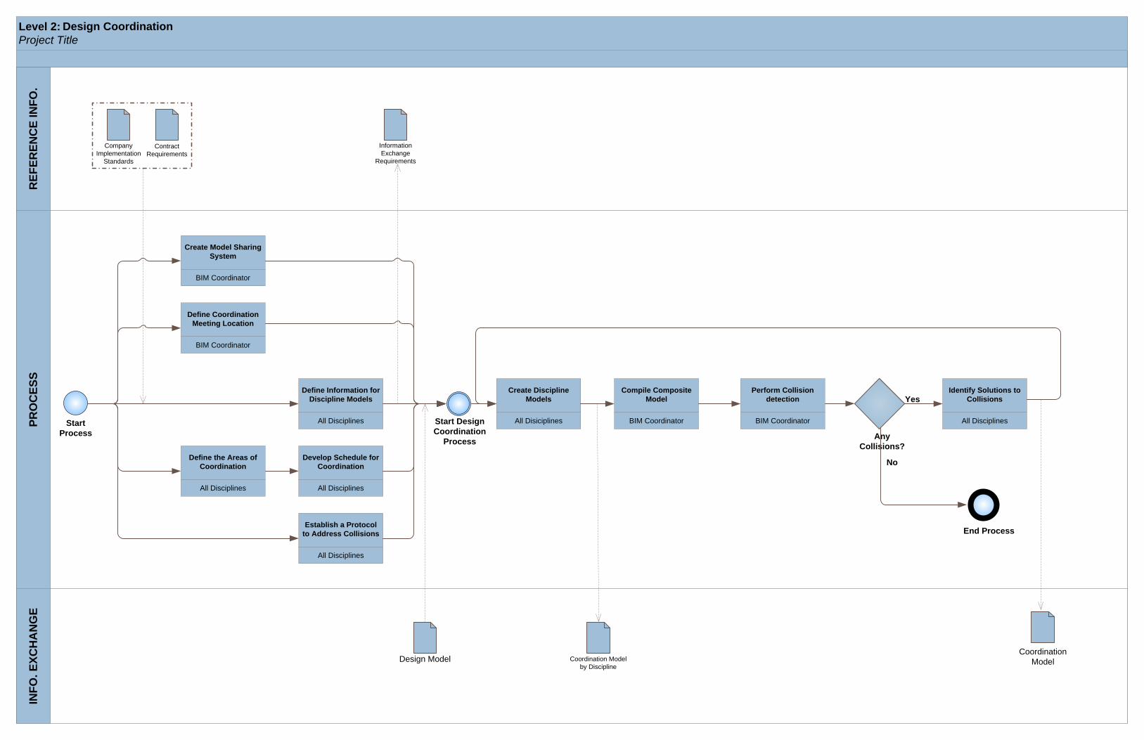
Level 2: Project Title
INFO
. EXC
HA
NG
ER
EFER
ENC
E IN
FO.
PRO
CES
SDesign Coordination
Start Process
BIM Coordinator
Create Model Sharing System
BIM Coordinator
Define Coordination Meeting Location
All Disciplines
Define Information for Discipline Models
All Disciplines
Define the Areas of Coordination
All Disciplines
Develop Schedule for Coordination
All Disciplines
Establish a Protocol to Address Collisions
Start Design Coordination
Process
All Disiciplines
Create Discipline Models
BIM Coordinator
Compile Composite Model
BIM Coordinator
Perform Collision detection
Any Collisions?
All Disciplines
Identify Solutions to CollisionsYes
No
End Process
Company Implementation
Standards
Contract Requirements
Information Exchange
Requirements
Design Model Coordination Model by Discipline
Coordination Model

Level 2: Project Title
INFO
. EXC
HA
NG
ER
EFER
ENC
E IN
FO.
PRO
CES
S
Start Process
End Process
No
Yes
ModelAcceptable?
EquipmentInformation
ProjectSubmittal
Information
Design Model Coordination Model
4D ModelRecord Model
Owner
Identify Information Requirements
Facility Manager
Compile Information
Facility Manager
Generate Additional Required Information
Record Modeling
Facility Manager
Compile Information in FM Application

Level 2: Project Title
INFO
. EXC
HA
NG
ER
EFER
ENC
E IN
FO.
PRO
CES
SCost Estimation
Start Process Model ready
for QTO/Cost Analysis?
Yes
No
Results Acceptable?
Yes
No
Contractor
Establish Cost Targets
Contractor
Adjust BIM for Takeoff
Contractor
Export BIM for Analysis
Contractor
Develop Quantities Schedule
Contractor
Review Quantities
Contractor
Evaluate Methods for Assembly Construction
Contractor
Organize Quantities to Cost
Data
Contractor
Calculate Costs from Quantities
Contractor
Review Costs/Results
Contractor
Incorporate Contingencies/
Overheads
Contractor
Evaluate Quantities and
Cost Breakdown
No
Yes
End Process
Results in Compliance with
Cost Target?
Cost Reports Analysis Method
3D Model Quantity Takeoff for Assemblies
Cost Estimate for Assemblies
Cost Database

Appendix B
Template Information Exchange Worksheet
This Appendix contains the Template IE worksheet using the CSI UNIFORMAT II
classification as the model element breakdown structure.
Table B-1: Legend for Information Content
Legend Information A Accurate Size & Location,
include materials and object parameters
B General Size & Location, include parameter data
C Schematic Size & Location
Table B-2: Legend for Responsible Party
Legend Responsible Party
A Architect C Contractor CV Civil Engineer FM Facility Manager MEP MEP Engineer SE Structural Engineer TC Trade Contractors

Info Resp Party Notes Info Resp
Party Notes Info Resp Party Notes Info Resp
Party Notes
A
Standard FoundationsSpecial FoundationsSlab on Grade
Basement ExcavationBasement Walls
B
Floor ConstructionRoof Construction
Exterior WallsExterior WindowsExterior Doors
Roof CoveringsRoof Openings
C
PartitionsInterior DoorsFittings
Stair ConstructionStair Finishes
Wall FinishesFloor FinishesCeiling Finishes
D
Elevators & LiftsEscalators & Moving WalksOther Conveying Systems
Plumbing FixturesDomestic Water DistributionSanitary WasteRain Water DrainageOther Plumbing Systems
Energy SupplyHeat Generating SystemsCooling Generating SystemsDistribution SystemsTerminal & Package UnitsControls & InstrumentationSystems Testing & BalancingOther HVAC Systems & Equipment
SprinklersStandpipesFire Protection SpecialtiesOther Fire Protection Systems
Electrical Service & DistributionLighting and Branch WiringCommunications & SecurityOther Electrical Systems
E
Commercial EquipmentInstitutional EquipmentVehicular EquipmentOther Equipment
Fixed FurnishingsMovable Furnishings
F
Special StructuresIntegrated ConstructionSpecial Construction SystemsSpecial FacilitiesSpecial Controls & Instrumentation
Building Elements DemolitionHazardous Components Abatement
Selective Bldg Demo
SERVICESConveying Systems
Plumbing
HVAC
Fire Protection
Electrical
EQUPMENT & FURNISHINGSEquipment
Furnishings
SPECIAL CONSTRUCATION & DEMOLITIONSpecial Construction
Interior Finishes
Model Element BreakdownSUBSTRUCTUREFoundations
Basement Construction
SHELLSuperstructure
Exterior Enclosure
Roofing
INTERIORSInterior Construction
Stairs
Application & VersionFile FormatTime of Exchange (SD, DD, CD, Construction)
Information Exchange 4INFORMATION EXCHANGE REQUIREMENTS
Information Exchange TitleInformation Exchange 1 Information Exchange 2 Information Exchange 3

G
Site ClearingSite Demolition & RelocationsSite EarthworkHazardous Waste Remediation
RoadwaysParking LotsPedestrian PavingSite DevelopmentLandscaping
Water Supply & Distribution SystemsSanitary Sewer SystemsStorm Sewer SystemsHeating DistributionCooling DistributionFuel DistributionOther Civil/Mechanical Utilities
Electrical DistributionSite LightingSite Communications & SecurityOther Electrical Utilities
Service TunnelsOther Site Systems & Equipment
1Construction EquipmentTemporary SafetyTemporary SecurityTemporary FacilitiesWeather Protection
2Construction Activity SpaceAnalysis Space
3Construction InformationEngineering InformationRecord Information
Construction Systems
Space
Information
BUILDING SITEWORKSite Preparation
Site Improvements
Site Civil/Mech Utilities
Site Electrical Utilities
Other Site Construction

Appendix C
Questionnaire Survey and Detailed Results
BIM Process Mapping Survey Name: __________________________
This survey is conducted for the sole purpose of research and the data collected will be kept confidential. Please give your comments and provide your responses on a scale of 1‐5 (1‐ strongly disagree to 5‐ strongly agree). Thank you for your time and cooperation!
1. What is your Academic Standing? (Check Appropriate Box)
4th Year 5th Year Graduate Other (Please describe below)
2. What is your experience level in BIM? (Check appropriate box)
None Somewhat familiar
Familiar Fairly well
Expert
Please indicate the extent to which you agree to the following statements.
Strongly Disagree Disagree Neutral Agree Strongly
Agree
3. I have knowledge about the BIM task for which I was creating the process map.
1 2 3 4 5
4. I have been directly or indirectly involved in creating process maps before.
1 2 3 4 5
5. I felt that the procedure was defined adequately.
1 2 3 4 5
6. I felt that the procedure allowed me to model all the aspects necessary to understand the BIM Use.
1 2 3 4 5
7. I felt that the procedure and the template map which was provided helped me in generating ideas for creating the process map.
1 2 3 4 5
8. Overall, I felt that the procedural steps and the template file provided in TIBCO were adequately detailed to create process map for the BIM Use.
1 2 3 4 5

121
9. This activity helped me gain a better understanding of the given BIM use.
1 2 3 4 5
10. I feel that a process map will communicate/explain the given process in a better way.
1 2 3 4 5
11. The swimlanes – (enterprise information, external information, process and BIM) helped me in understanding the task.
1 2 3 4 5
12. I felt comfortable using TIBCO to create process maps.
1 2 3 4 5
13. What challenges did you have while creating the process map? ________________________________________________________________________________________________________________________________________________________________________________________________________________________________________________________________________________________________________________________________________________________________________________________________________ 14. What additional steps/instructions will you like to see included in the procedure or the template file provided. ____________________________________________________________________________________________________________________________________________________________________________________________________________________________________________________________________________________________________________________________________________________________________________________________________
15. How long did it take you to a) Orient yourself to TIBCO ____________________________? b) Develop this map___________________________________?
16. Please provide any additional comments. _______________________________________________________________________________________________________________________________________________________________________________________________________________________________________________________________________________________________________________________________________________________________________________________________________

122
Detailed Survey results
Strongly disagree0%
Disagree0%
Neutral9%
Agree55%
Strongly agree36%
Question 3: I have knowledge about the BIM task for which I was creating the process map.
Strongly disagree
Disagree
Neutral
Agree
Strongly agree
Strongly disagree9%
Disagree18%
Neutral18%
Agree46%
Strongly agree9%
Question 4: I have been directly or indirectly involved in creating process maps before.
Strongly disagree
Disagree
Neutral
Agree
Strongly agree

123
Strongly disagree
0%
Disagree0% Neutral
9%
Agree55%
Strongly agree36%
Question 5: I felt that the procedure was defined adequately.
Strongly disagree
Disagree
Neutral
Agree
Strongly agree
Strongly disagree
0%
Disagree0%
Neutral46%
Agree45%
Strongly agree9%
Question 6: I felt that the procedure allowed me to model all the aspects necessary to understand the BIM Use.
Strongly disagree
Disagree
Neutral
Agree
Strongly agree

124
Strongly disagree0%
Disagree0%
Neutral0%
Agree64%
Strongly agree36%
Question7: I felt that the procedure and the template map which was provided helped me in generating ideas for
creating the process map.
Strongly disagree
Disagree
Neutral
Agree
Strongly agree
Strongly disagree0%
Disagree0%
Neutral9%
Agree55%
Strongly agree36%
Question8 : Overall, I felt that the procedural steps and the template file provided in TIBCO were adequately detailed to
create process map for BIM use.
Strongly disagree
Disagree
Neutral
Agree
Strongly agree

125
Strongly disagree0%
Disagree0%
Neutral37%
Agree36%
Strongly agree27%
Question 9: This activity helped me gain a better understanding of the given BIM use.
Strongly disagree
Disagree
Neutral
Agree
Strongly agree
Strongly disagree0%
Disagree0%
Neutral27%
Agree27%
Strongly agree46%
Question 10: I feel that a process map will communicate/explain the given process in a better way.
Strongly disagree
Disagree
Neutral
Agree
Strongly agree

126
Strongly disagree0% Disagree
9%
Neutral37%
Agree36%
Strongly agree18%
Question 11: The swimlanes – (enterprise information, external information, process and BIM) helped me in understanding the
task.
Strongly disagree
Disagree
Neutral
Agree
Strongly agree
Agree55%
Strongly agree45%
Question 12: I felt comfortable using TIBCO to create process maps.
Strongly disagree
Disagree
Neutral
Agree
Strongly agree

127
Symbols used for Process Map Representation
Element Description Notation Event An event is something that “happens” during the
course of a business process. These events affect the flow of the process and usually have a cause (trigger) or an impact (result). Events are circles with open centers to allow internal markers to differentiate different triggers or results. There are three types of Events, based on when they affect the flow: Start, Intermediate, and End.
Activity An activity is a generic term for work that company performs. An activity can be atomic or non-atomic (compound). The types of activities that are a part of a Process Model are: Process, Sub-Process, and Task. Tasks and Sub- Processes are rounded rectangles. Processes are contained within a Pool.
Gateway A Gateway is used to control the divergence and convergence of Sequence Flow. Thus, it will determine branching, forking, merging, and joining of paths. Internal Markers will indicate the type of behavior control.
Sequence Flow A Sequence Flow is used to show the order that activities will be performed in a Process.
Association An Association is used to associate information with Flow Objects. Text and graphical non-Flow Objects can be associated with Flow Objects. An arrowhead on the Association indicates a direction of flow (e.g., data), when appropriate.
Pool A Pool represents a Participant in a Process also acts as a “swimlane” and a graphical container for partitioning a set of activities from other Pools.
Lane A Lane is a sub-partition within a Pool and will extend the entire length of the Pool, either vertically or horizontally. Lanes are used to organize and categorize activities.
Data Object Data Objects are considered Artifacts because they do
not have any direct effect on the Sequence Flow or

128
Message Flow of the Process, but they do provide information about what activities require to be performed and/or what they produce.
Group A grouping of activities that are within the same
category. This type of grouping does not affect the Sequence Flow of the activities within the group. The category name appears on the diagram as the group label. Categories can be used for documentation or analysis purposes.

Appendix D
Case Study Process Maps and Information Exchange Worksheet
This appendix contains the PMs and the IE for the MSC Project.
• BIM Overview Map;
• Detailed BIM Use Process Map for Design Authoring;
• Detailed BIM Use Process Map for Design Coordination;
• Detailed BIM Use Process Map for 4D Modeling;
• Detailed BIM Use Process Map for Record Modeling; and
• IE for MSC Project

Level 1: Overall MapMillennium Science Complex ProjectIN
FOR
MA
TIO
N E
XCH
AN
GE
BIM
USE
SDeveloped with the BIM Execution Planning Procedure by the Penn State CIC Research Team.
http://bimex.wikispaces.com
RVA, TTE, F+ K
Design Development
Design Authoring
Author the Design Model
Whiting-Turner
Construction Documents
4D Modeling
Perform 4D Modeling
Whiting-Turner
Construction Documents
3D Design Coordination
Perform 3D Coordination
Whiting-Turner
Operations
Record Model
Compile Record Model
Arch Model Struct Model MEP ModelCoordination
Model4D Model Record Model
Responsible Party
Project Phase
Template Process
Process Name
LEGEND
Input Process Output Process

Level 2: Millennium Science Complex Project
INFO
. EXC
HA
NG
ER
EFER
ENC
E IN
FOR
MA
TIO
NPR
OC
ESS
Developed with the BIM Execution Planning Procedure by the Penn State CIC Research Team.http://bimex.wikispaces.com
Start Process
All Disciplines
Identify Models Required
All Disciplines
Identify Content for Model Creation
RVA (Revit 2009)
Develop Intitial Architecture Model
RVA (Revit 2009)
Create Schematic Design Architecture
Model
TTE (Revit 2009)
Create Schematic Design Structural
Model
F+ K (Revit 2009)
Create Schematic Design MEP Model
Does the model meet the
requirements?
RVA (Revit 2009)
Create Design Development
Architecture Model
TTE (Revit 2009)
Create Design Development
Structural Model
F + K (Revit 2009)
Create Design Development MEP
Model
Does the model meet the
requirements?
RVA (Revit 2009)
Create Construction Documentation
Architecture Model
TTE (Revit 2009)
Create Construction Documentation
Structural Model
F + K (Revit 2009)
Create Construction Documentation MEP
Model
Does the model meet the
requirements?
Preliminary Architecture Model
Yes
No
Yes
No
Arch Model
MEP Model
Struct Model
Schematic Design
End Process
Design Authoring
Arch Model
MEP Model
Struct Model
Design Development
Arch Model
MEP Model
Struct Model
Construction Documentation
Yes
No

Level 2: Millennium Science Complex Project
INFO
. EXC
HA
NG
ER
EFER
ENC
E IN
FOR
MA
TIO
NPR
OC
ESS
Developed with the BIM Execution Planning Procedure by the Penn State CIC Research Team.http://bimex.wikispaces.com
Design Coordination
Start Process
BIM Coordinator
Set up the FTP Site
BIM Coordinator
Define Coordination Meeting Location
All Disciplines
Define Information for Discipline Models
All Disciplines
Define the Areas of Coordination
Whiting-Turner
Develop Schedule for Coordination
All Disciplines
Establish a Protocol to Address Collisions
Start Design Coordination
Process
All Disiciplines
Create Discipline Models
Whiting-Turner
Load and Compile models
Are there any unresolved collisions
All Disciplines
Revise discipline models
Yes
No
End Process
Company Implementation
Standards
Contract Requirements
Information Exchange
Requirements
MEP model Discipline Models
Coordinated Model
All Disciplines
Identify Solutions to Collisions
Whiting-Turner
Run Clash Detective
Whiting-Turner
Generate views of clashes
All Disciplines
Coordination drawings sign off
Struct Model
Arch Model
Coordination Models (*.nwd)

Level 2: Millennium Science Complex Project
INFO
. EXC
HA
NG
ER
EFER
ENC
E IN
FOR
MA
TIO
NPR
OC
ESS
Developed with the BIM Execution Planning Procedure by the Penn State CIC Research Team.http://bimex.wikispaces.com
Start Process
Model Correct?
No
Yes
Schedule Optimized?
Yes
No
End Process
Struct Model
Schedule (Draft)
4D Model(Draft)
Schedule 4D Model
Whiting-Turner,Sub-contractors
Create Construction Schedule
Whiting-Turner
Create temporary equipment model
Whiting-Turner
Compile Synchro Geometry
Whiting-Turner
Link 3D Elements to Activities
Whiting-Turner
Validate Accuracy of 4D Model
Whiting-Turner, Sub-contractors, OPP
Review 4D Model/Schedule
4D Modeling
Arch Model Temporary Equipment Model
Synchro Geometry Model

Level 2: Millennium Science Complex Project
INFO
. EXC
HA
NG
ER
EFER
ENC
E IN
FOR
MA
TIO
NPR
OC
ESS
Developed with the BIM Execution Planning Procedure by the Penn State CIC Research Team.http://bimex.wikispaces.com
Start Process End Process
No
Yes
ModelAcceptable?
EquipmentInformation
ProjectSubmittal
Information
Design Model
Arch Model MEP Model Coordination Model 4D Model Record Model
Whiting-Turner, RVA, OPP
Identify Information Requirements
Whiting-Turner
Compile Information
OPP
Generate Additional Required Information
Struct Model
Record Modeling
OPP
Compile information in FM application

135
Table D-1: Legend for Information Content used for the Case Study
Legend Information A Accurate Size & Location,
include materials and object parameters
B General Size & Location, include parameter data
C Schematic Size & Location
Table D-2: Legend for Responsible Party used for the Case Study
Legend Responsible Party RVA Architect (Rafeal Viñoly Architects) TTE Structural Steel Engineers (Thornton
Tomasetti) Kinsley Structural Steel Designers Farfield HVAC Piping/ductwork/equipment
WT General Contractor ( Whiting-Turner)
F&K Mechanical Engineer (Flack + Kurtz) McClure Plumbing Sub-contractor
Biter Electrical Sub-contractor Herre Plumbing Sub-contractor
Comunale Fire Protection

Info Resp Party Notes Info Resp
Party Notes Info Resp Party Notes Info Resp
Party Notes Info Resp Party Notes
A
Standard Foundations C RVA A TTE A TTE A Kinsley B KinsleySpecial Foundations C RVA A TTE A TTE A Kinsley B KinsleySlab on Grade C RVA A TTE A TTE A Kinsley B Kinsley
Basement Excavation A RVA A RVA A RVA A WT B WTBasement Walls A RVA A RVA A RVA A WT B WT
B
Floor Construction A RVA A RVA A RVA A Kinsley B KinsleyRoof Construction A RVA A RVA A RVA A Kinsley B Kinsley
Exterior Walls A RVA A RVA A RVA A BExterior Windows A RVA A RVA A RVA A BExterior Doors A RVA A RVA A RVA A B
Roof Coverings A RVA A RVA A RVA A WT B WTRoof Openings A RVA A RVA A RVA A WT B WT
C
Partitions A RVA A RVA A RVA A WT B WTInterior Doors A RVA A RVA A RVA A WT B WTFittings A RVA A RVA A RVA A WT B WT
Stair Construction C RVA A TTE A TTE A Kinsley B TTEStair Finishes C RVA A TTE A TTE
Wall Finishes A RVA A RVA A RVA AFloor Finishes A RVA A RVA A RVA ACeiling Finishes A RVA A RVA A RVA A
D
Elevators & Lifts A Farfield A FarfieldEscalators & Moving WalksO C S
INFORMATION EXCHANGE REQUIREMENTS
Information Exchange Title Architecture Model Structural Model Mechanical Model 4D ModelTime of Exchange (SD, DD, CD, Construction) DD DD DD CD DD,CD
Coordination Model
Reciever File Format *.rvt *.rvt *.rvt *.nwd
Stairs
Model Element BreakdownSUBSTRUCTUREFoundations
Basement Construction
SHELL
Application & Version Revit 2009 Revit 2009 Revit 2009 Navisworks 2010
Superstructure
Exterior Enclosure
Roofing
INTERIORSInterior Construction
Interior Finishes
SERVICESConveying Systems
Other Conveying Systems
Plumbing Fixtures A F&K AHerre,
McCLure
Domestic Water Distribution A F&K AHerre,
McCLure
Sanitary Waste A F&K AHerre,
McCLure
Rain Water Drainage A F&K AHerre,
McCLure
Other Plumbing Systems
Energy Supply A F&K A FarfieldHeat Generating Systems A F&K A FarfieldCooling Generating Systems A F&K A FarfieldDistribution Systems A F&K A FarfieldTerminal & Package Units A F&K A FarfieldControls & Instrumentation F&K FarfieldSystems Testing & Balancing A F&K A FarfieldOther HVAC Systems & Equipment
Sprinklers ACommunal
e
Standpipes ACommunal
eFire Protection SpecialtiesOther Fire Protection Systems
Electrical Service & Distribution A BiterLighting and Branch Wiring A BiterCommunications & Security A BiterOther Electrical Systems A Biter
E
Commercial EquipmentInstitutional EquipmentVehicular EquipmentOther Equipment
Fixed Furnishings AMovable Furnishings
F
Special StructuresIntegrated ConstructionSpecial Construction SystemsSpecial FacilitiesSpecial Controls & Instrumentation
Building Elements DemolitionHazardous Components Abatement
G
Site ClearingSite Demolition & RelocationsSite EarthworkHazardous Waste Remediation
RoadwaysParking LotsPedestrian PavingSite DevelopmentLandscaping
Water Supply & Distribution Systems
Special Construction
Plumbing
HVAC
Fire Protection
Electrical
EQUPMENT & FURNISHINGSEquipment
Furnishings
SPECIAL CONSTRUCATION & DEMOLITION
Selective Bldg Demo
BUILDING SITEWORKSite Preparation
Site Improvements
Site Civil/Mech Utilities

Sanitary Sewer SystemsStorm Sewer SystemsHeating DistributionCooling DistributionFuel DistributionOther Civil/Mechanical Utilities
Electrical DistributionSite LightingSite Communications & SecurityOther Electrical Utilities
Service TunnelsOther Site Systems & Equipment
1Construction EquipmentTemporary SafetyTemporary SecurityTemporary FacilitiesWeather Protection
2Construction Activity SpaceAnalysis Space
3Construction InformationEngineering InformationRecord Information
Other Site Construction
Construction Systems
Space
Information
Site Electrical Utilities