a practical-approach-to-motor-vehicle-engineering-and-maintenance-second-edition-allan bonnick,
Post on 11-Sep-2014
479 views
DESCRIPTION
TRANSCRIPT


A Practical Approach toMotor Vehicle Engineeringand Maintenance


A Practical Approach toMotor Vehicle Engineeringand Maintenance
Second Edition
Derek NewboldFormerly of Hinckley College
Allan Bonnick, M.Phil, B.Sc, C.Eng, M.I.Mech.Eng
Formerly Principal Lecturer at Eastbourne College of Arts and Technology
AMSTERDAM . BOSTON . HEIDELBERG . LONDON . NEW YORK . OXFORD
PARIS . SAN DIEGO . SAN FRANCISCO . SINGAPORE . SYDNEY . TOKYO

Elsevier Butterworth-HeinemannLinacre House, Jordan Hill, Oxford OX2 8DP30 Corporate Drive, Burlington, MA 01803
First published by Arnold 2000Reprinted 2002, 2003, 2004Second edition 2005
Copyright 2005, Derek Newbold and Allan Bonnick. All rights reserved.
The rights of Derek Newbold and Allan Bonnick to be identified as theauthors of this work has been asserted in accordance with the Copyright,Designs and Patents Act 1988
No part of this publication may be reproduced in any material form(including photocopying or storing in any medium by electronic meansand whether or not transiently or incidentally to some other use of thispublication) without the written permission of the copyright holder exceptin accordance with the provisions of the Copyright, Designs and PatentsAct 1988 or under the terms of a licence issued by the Copyright LicensingAgency Ltd, 90 Tottenham Court Road, London, England W1T 4LP.Applications for the copyright holder’s written permission to reproduceany part of this publication should be addressed to the publisher
Permissions may be sought directly from Elsevier’s Science & TechnologyRights Department in Oxford, UK: phone: (þ44) (0) 1865 843830,fax: (þ44) 1865 (0) 853333, e-mail: [email protected]. You may alsocomplete your request on-line via the Elsevier homepage(http://www.elsevier.com), by selecting ‘Customer Support’ and then‘Obtaining Permissions’
British Library Cataloguing in Publication Data
A catalogue record for this book is available from the British Library
Library of Congress Cataloguing in Publication Data
A catalogue record for this book is available from the Library of Congress
ISBN 0 7506 6314 6
For information on all Elsevier Butterworth-Heinemannpublications visit our website at http://books.elsevier.com
Typeset by Integra Software Services Pvt. Ltd, Pondicherry, Indiawww.integra-india.comPrinted and bound in Great Britian
Working together to grow libraries in developing countries
www.elsevier.com | www.bookaid.org | www.sabre.org

Contents
Foreword viii
Foreword to second edition ix
Acknowledgements x
Introduction to the retail motor industry and Health & Safety at Work 1
Detail of the motor vehicle maintenance and repair industryAn introduction to Health & Safety at Work
1 Engines and lubrication 11
Engine constructionFour stroke and two stroke cyclesValve timing – variable valve timingCombustionLubrication and lubrication systems
2 Cooling systems 58
Cooling system terminologyLiquid (water) cooled systemAir-cooled systemAnti-freezeSpecific heat capacityFans and pumps
3 Fuel systems 85
Petrol fuel systemPetrol injectionCarburettorsDiesel fuel systemsDirect injection – indirect injectionCommon rail fuel system
4 Engine air supply and exhaust systems 128
Engine air supply – air filters – manifoldsExhausts systems – silencersOxygen sensorAir flow metersTurbo-charger
5 Transmission systems 141
ClutchGearboxFluid flywheel and torque convertorTransmission systems – drive shafts

Hub types – semi-floating, fully floating, three-quarter floatingGear ratios – torque multiplication
6 Suspension systems 170
Non-independent – leaf spring suspensionIndependent suspensionLeaf spring constructionDampers (shock absorbers)
7 Braking systems 186
Hydraulic braking systemsDrum brakesDisc brakesMaster cylinderWheel cylindersBrake fluidBraking efficiency
8 Steering, wheels and tyres 200
Ackerman principleSteering anglesSteering geometryTrack adjustmentSteering boxesToe-out on turns
9 Electrical and electronic principles 224
Principles of magnetism and electricityIntroductory electronicsComputer controlled systemsNetworking and CANMultiplexingMeters
10 Electrical and electronic systems 243
AlternatorBatteryCharging systemStarting systemsElectrical principles
11 Ignition systems 260
Ignition systems – coil, capacitor (condenser)Electronic ignition systems, non-electronic ignition systemsFault tracing and service and maintenance proceduresSensors and pulse generatorsIgnition timingDiagnostic trouble codes
12 Electrical systems and circuits 297
Central lockingScreen wipersVehicle security alarmElectric windowsScreen washers
vi Contents
Electric mirrorsVehicle lighting systemsSupplementary restraint systems – airbags and seatbelt pre-tensioners
13 Measuring instruments and measurement 331
MicrometersVernier calipersFeeler gaugesNumber approximations – typical motor vehicle measurementsElectrical test meters
14 Organisations and qualifications 348
Organisations in the motor tradeQualifications and careers
Answers to self assessment questions 351
Index 353
Contents vii

Foreword
Although this book has been written mainly forthose who wish to gain an NVQ in motor vehi-cle work, it is equally suitable for a wide varietyof people who are undertaking the City &Guilds, BTEC as well those who just want toknow about cars to enable them to undertaketheir own servicing with a greater degree ofconfidence. It can be used in schools, collegesand garage workshops as each task is beingundertaken.
It covers the fundamental principles for eachsystem found in the motor vehicle. It is by nomeans exhaustive, but it does allow the studentto take simple steps in understanding how eachsystem works.
The NVQ qualification is not as daunting asmany people think. The main problem seems tobe in the gaining of evidence and the assemblingof a portfolio, so, with this in mind, there are anumber of exercises at the end of each sectionfor the student to complete. The evidencerequired by the NVQ assessor from the studentwill be gained gradually and built into a studentportfolio. Each completed job sheet (suitablysigned after the job has been checked) shouldshow evidence of what you have done, how youdid it and that it was completed to a satisfactorystandard. When the student feels confidentenough to complete the task alone then he orshe may request an assessment. Examples ofassessments are given in the book to show whatmight be required by the assessor.
The text has a number of words and sentencesthat are highlighted when they first appear inthe text. These are mostly key words that willhelp the student to remember what is essentialfrom the text. No matter how much the student‘waffles’ when answering questions, unless he or
she understands the subject and uses the keywords, it will be very difficult for the assessorto give marks. Remember the key words andyou will be half-way there. Some of the wordsused are specific to the motor vehicle and to theNVQ. We have tried to explain those relating tothe motor vehicle in the text and those relatingto the NVQ in a glossary at the end of the book.There are a number of practical assignmentsand learning tasks in each chapter. If these areundertaken in a realistic way, they will enablethe student to complete the task repeatedly, upto an acceptable standard, without supervision,which is the requirement of the NVQ.
The workshop job sheet should contain allthe elements of the performance criteria asrequested in the NVQ. They should be signedby both the person undertaking the task (you)and the assessor/supervisor to say the task hasbeen completed satisfactorily.
The illustrations have been selected to givethe maximum amount of support when learn-ing about new topics. We advise students toattempt the learning tasks when they havecompleted the related section of their trainingand education.
This book is based on many years of teachingand helping students and apprentices who havegone on to become successful and valuedmechanics. Some of them have become ownersof their own motor vehicle workshops, each inturn has appreciated the training that was givento them in their early years. Our hope is that thisbook will enable a wider variety of people toachieve their hopes and ambitions.
Derek NewboldAllan Bonnick

Foreword to second edition
In order to take account of feedback frompractising teachers and to allow for develop-ments in technology, education and trainingthis 2nd edition includes coverage of develop-ments such as; variable value timing, on boarddiagnostics, computer controlled systems etc.
maintenance aspects are covered and a rangeof learning tasks and self assessment questionis included.
Allan Bonnick2005

Acknowledgements
Thanks are due to the following companies whosupplied information and in many cases permis-sion to reproduce photographs and diagrams:
. Audi UK Ltd
. Bowers Metrology Group (Moore & Wright)
. Champion Spark Plugs Ltd
. Crypton Technology Group
. Cummins Engine Company Inc.
. Delmar Publishers Inc.
. Dunlop Holdings Ltd
. Ford Motor Company UK Ltd
. Haynes Publications
. Honda UK Ltd
. KIA Cars Ltd
. Lucas Automotive Ltd
. Rover Group
. Vauxhall Motors Ltd
. Volvo Group (UK)
. Toyota GB Ltd
. Zahnradfabrik Friedrichshafen AG
Special thanks are due to the following for sup-plyingmuch useful information, and with permis-sion to reproduce pictures and diagrams from:
The Automotive Chassis: Engineering princi-ples 2nd edition, J Reimpell & H Stoll(Vogel-Buchverlag, Wurzburg, 1995)
If we have used information or mentioned acompany name in the text, not listed here, ourapologies and acknowledgements.

Introduction to the retail motor industryand Health & Safety at Work
Motor vehicle maintenance andrepair
This introductory section contains:
. Details of the motor vehicle maintenance andrepair industry;
. An introduction to Health & Safety at Work.
The motor vehicle maintenance andrepair industry – the garage industry
By taking a few examples of aspects ofmodern life, it is possible to gain an insightinto areas of activity where motor vehiclemaintenance and repair plays an importantpart. One has only to consider the effect ofa vehicle breakdown in any of these areas togain an appreciation of the part that motorvehicle technicians play in the day-to-dayoperation of society when they maintain andrepair vehicles.
In order for these activities to take place,the vehicles must be serviced and maintainedat regular intervals and, in the event of abreakdown, action must be taken to clearthe road and repair the vehicle so as torestore it to good working condition, asquickly as possible. In the UK it is the motorvehicle repair and maintenance industry thatperforms the bulk of vehicle maintenance andrepair work. It is for trainees and students,preparing for work in this industry, that thisbook is designed.
Some details about the type of workinvolved in repair and maintenanceof vehicles
There are approximately 30 000 000 vehicles ofvarious types in use in the UK in 2004 and alarge vehicle repair and maintenance industryexists to provide the necessary services. The
Area of activity Type of activity Type of vehicle
Personal transport Getting to work. Taking children to school. Cars, people carriers, motorcycles,
scooters and mopedsGoing on holiday. Visiting friends.
Going shopping
Public transport Activities as for personal transport, but
much more important in towns and cities
where traffic congestion causes delays
Buses, coaches
Good vehicles Movement of food, fuel, materials for industry.
Bringing food and materials into the country.
Trucks, vans, tankers, articulated vehicles
Exporting manufactured goods, etc.
Emergency services Fire and rescue services. Cars, vans, fire engines, rescue vehicles,
mobile cranesAmbulances. Doctors. Movement of blood
supplies and human organs.
AA, RAC and other forms of roadside assistance
Armed forces Defence of the realm. Action overseas.
Maintenance of services in times of need
Trucks, armoured vehicle, tanks, fuel
tankers, tank transporters
Postal and other
delivery services
Communications for business Vans, trucks
Private correspondence. Delivery of
mail order goods
Fuel deliveries Fuel deliveries to service stations and fuel
depots. Domestic fuel supplies
Tankers of various sizes

majority of motor cars are repaired and main-tained in retail garages and businesses vary insize, from large-sized vehicle dealershipsemploying several people in a range of occupa-tions to small one man type businesses. Busestend to be cared for in specialised workshopsoperated by Local Authorities and specialisedbus companies. The repair and maintenance ofheavy goods vehicles is often carried out in gar-age workshops that are owned by transportcompanies.
The garage industry employs several hundredthousand people in a range of occupations. Thework is interesting, often demanding –both physically and mentally. There are manyopportunities for job satisfaction. For example,it is most rewarding to restore a vehicle to fullworking condition after it has suffered someform of failure. There are opportunities forpromotion, technicians often progressing toservice managers and general managers, or torun their own companies. The Office of FairTrading (OFT) report for the year 2000 showsthat more than 50% of cars were more than5 years old. These cars require annual MOTinspections and there is a tendency for them tobe serviced and repaired in the independentsector of the industry. The OFT report showsthat there are approximately 16 000 indepen-dent garages and 6 500 garages that arefranchised to one or more motor manufacturers.Evidently there are plenty of opportunities foremployment.
Health and safety
It is the responsibility of every person involvedin work to protect their own safety and that ofany other persons who may be affected by theiractivities. At the basic level this means thateveryone must work in a safe manner and knowhow to react in an emergency. Personal cleanli-ness issues such as regular washing, removal ofsubstances from skin, use of barrier creams, useof protective clothing and goggles and gloves,etc. are factors that contribute to one’s wellbeing. Behaving in an orderly way, not indul-ging in horseplay, learning how to employ safeworking practices and helping to keep the work-place clean and tidy, are all ways in which anindividual can contribute to their own andothers health and safety at work.
There are various laws and regulations thatgovern working practice in the motor vehiclerepair industry, in the UK – the main ones are:
. Health & Safety at Work Act 1974;
. The Factories Act 1961;
. The Offices, Shops and Railway PremisesAct 1963.
Some of the other regulations that relate to safetyin motor vehicle repair and maintenance are:
. The Control of substances Hazardous toHealth (COSHH) Regulations 1988;
. Regulations about the storage and handlingof flammable liquids;
. The Grinding Wheel Regulations.
Health and safety laws are enforced by a factoryinspector from the Health and Safety Executive(HSE) or an environmental health officer fromthe local council.
Safety policy
As stated at the beginning of this section, eachindividual has a responsibility to work safelyand to avoid causing danger to anyone else.This means that each individual must knowhow to perform their work in a safe way andhow to react with other people in the event of anaccident or emergency. In any establishment,however small, safety planning must be per-formed by a competent person, who must thenfamiliarise all others engaged in the enterprisewith the plans that have been devised, to ensurethat all health and safety issues are properlycovered. These plans are a set of rules andguidelines for achieving health and safety stan-dards, in effect a policy.
Every motor vehicle repair business thatemploys five or more people must write downtheir policy for health and safety and have it tohand for inspection by the HSE.
Motor vehicle repair andmaintenance health and safetytopics
Readers are advised to purchase a copy of thepublication ‘‘Health & Safety in Motor VehicleRepair – HSG67’’ available from HMSO forapproximately £5.50. The HSE website:www.hse.gov.uk is also a valuable source ofinformation. Several pages are devoted tomotor vehicle repair and the home page offersthe user the opportunity to select ‘your indus-try’, a click on ‘Motor vehicle repair’ brings upmany opportunities to study a variety of healthand safety topics.
2 A practical approach to motor vehicle engineering and maintenance

This publication (HSG67) states that:
‘‘Most accidents involve trips and falls orpoor methods of lifting and handling; seriousinjuries often resulting from these apparentlysimple causes. Accidents involving vehiclesare frequent and cause serious injuries anddeaths every year. Work on petrol tanks inparticular causes serious burns, hundreds offires and some deaths each year . . . There isalso widespread potential for work relatedill-health in garages. Many of the substancesused require careful storage, handling andcontrol.’’(HSE (2004) Health & safety in Motor
Vehicle Repair. HMSO)
From this you might think that motor vehiclework is hazardous but, if work is carried outproperly and safety factors are always consid-ered, it is possible to work without injury toanyone. Safety training and related skills train-ing must figure prominently in any course ofeducation and training that aims to preparepeople for work in motor vehicle maintenanceand repair. The following descriptions areintended to highlight some of the everydaysafety issues.
The information contained in this book doesnot attempt to provide full coverage of all safetyand health issues. The information providedmerely draws attention to some safety issues,and is not intended to cover all areas of safety.Readers should ensure that any educationcourse, training scheme, apprenticeship or other
training arrangement, does contain all necessarysafety training.
Lifting equipment
The types of lifting equipment that arecommonly used in vehicle repair workshopsare: jacks of various types, axle stands, vehiclehoists (lifts), floor cranes and vehicle recoveryequipment. Hydraulic jacks are used to raise thevehicle. For work to be done underneath thevehicle, the vehicle must be on level ground,and the wheels that are remaining on the groundmust be chocked or have the handbrake applied.Axle stands must be placed in the correct posi-tions before any attempt is made to get underthe vehicle. Figure A.1.1 shows the hydraulic jackplaced at a suitable jacking point. This is impor-tant: i) to ensure that the jacking point is securefrom the safety point of view; and ii) to preventdamage to the vehicle.
Hydraulic jacks must be maintained in goodcondition. The safe working load must beclearly marked on the jack. Axle stands mustbe of good quality and of a load carrying capa-city that is correct for the vehicle being sup-ported on them. The proper pins that allow forheight adjustment should be attached to thestands and the stands must be kept in goodcondition.
Vehicle hoists
The two-post vehicle hoist shown in Fig. A.1.2is an example of a type that is widely used in
ER/11/5 TI
(a)
ER/11/6 T1
(b)
Fig. A.1.1(a) Hydraulic jack positioned at jacking point, (b) Axle stands in position prior to working under the vehicle.
(Reproduced with the kind permission of Ford Motor Company Limited.)
Introduction to the retail motor industry and Health & Safety at Work 3

the garage industry. The HSE guide (HSG67)states:
‘‘Careful attention should be paid to manufac-turers’ recommendations when using two-posthoists – vehicle chassis, sub frame and jackingpoints should be in good condition; supportarms should be set to the correct height beforethe vehicle is raised. The weight distributionof the vehicle being lifted and the effect ofthe removal of major components should beconstantly evaluated.’’
Comment
Hoists, in common with other equipment, shouldnot be used until the method of operation isproperly understood. For trainees this meansthat proper training must be provided andtrainees should not attempt to use hoists untilthey have been trained and given permission todo so. Part of that training will be a demonstra-tion of the procedure for locating jacking pointsand positioning the support arm pads. Thisensures that the vehicle will be stable when liftedand the support arm pads prevent damage to thevehicle structure. The weight distribution of thevehicle on the hoist will be affected according tothe work being performed. For example, if thehoist is being used during a transmission unitchange, the removal of the transmission unit willgreatly affect weight distribution and this mustbe allowed for as the work progresses.
Four post hoists. The HSE guide says that:
‘‘Four-post hoists should have effective ‘deadman’s’ controls, toe protection and auto-matic chocking. Toe traps should also beavoided when body straightening jigs arefitted. Raised platforms should never be usedas working areas unless proper working bal-conies or platforms with barrier rails areprovided.’’
Comment
The dead man’s control is designed to avoidmishaps during the raising and lowering of thehoist. Toe protection is to prevent damage tothe feet when the hoist is lowered to the ground,and the automatic chocking is to prevent thevehicle from being accidentally rolled off theraised hoist. Body straightening jigs are used invehicle body repair shops and their use requiresspecial training. The point about working abovefloor level and the use of balconies should benoted.
In general, hoists make work on the undersideof a vehicle less demanding than lying on one’sback. A point to note is that hard hats should beworn when working under a vehicle on a hoist.The area around the hoist must be kept clearand a check should always be made when low-ering or raising at hoist to ensure that noperson, vehicle or other object is likely to be
Fig. A.1.2 Wheel free. Post hoist. (Reproduced with the kind permission of Ford Motor Company Limited.)
4 A practical approach to motor vehicle engineering and maintenance

harmed by the operation. Hoists must befrequently examined to ensure that they aremaintained in safe working order.
Electrical safety
Safety in the use of electrical equipment mustfigure prominently at all stages of training.
Learning task
As an exercise to develop knowledge in this
area you should now read pages 4 and 5 of
HSG67 and compare that with the training
and tuition that you are receiving. Also visit
the HSE motor vehicle repair website and
study what it has to say about electrical safety.
Check with your supervisor to make sure that
you know what to do in the event of an elec-
trical emergency in your present circum-
stances.
Compressed air equipment
Compressed air is used in a number of vehiclerepair operations such as tyre inflation,pneumatic tools, greasing machines and oil dis-pensers, etc. The compressed air is suppliedfrom a compressor and air cylinder and this isequipment that must be inspected regularly by acompetent person. The usual procedure is forthe insurance company to perform this work.Air lines, hoses, tyre inflaters and pressuregauges, couplings, etc. should be inspected atregular intervals to ensure that they are kept inworking order. Inflation of the split rim type ofcommercial vehicle tyres requires special atten-tion and the tyres should only be inflated behinda specially designed guard. An HSE bookletHSG62 covers many aspects of health andsafety for those engaged in tyre and exhaustfitting work.
Learning task
Read page 6 of HSG67 and note particularly
items 43 and 45. Visit the HSE website to see
what it has to say that is relevant to motor
vehicle repair.
Petrol fires
Referring back to the statement at the beginningof this section we have:
‘‘Work on petrol tanks in particular causesserious burns, hundreds of fires and somedeaths each year.’’
Comment
Petrol gives off a flammable vapour that is hea-vier than air; this means that it will settle at a lowlevel and spread over a wide area. Petrol vapouris also invisible. The vapour can be ignited by aflame or spark at some distance from any visiblesign of the liquid. Great care must be exercisedwhen dealing with petrol and the appropriate fireextinguisher should be close to hand when per-forming any task involving petrol or any otherflammable substance. Petrol may only be storedin containers specified in the Petroleum SpiritRegulations. Advice on this is readily availablefrom the local Fire Authority. In the event ofspillage on clothes, the clothes should beremoved for cleaning because petrol vapour canaccumulate inside the clothing which can resultin serious burns in the event of ignition.
Learning task
Read page 8 of HSG67. What does HSG67 say
about the fuel gauge sender unit? Discuss this
with your tutor/trainer, or supervisor.
Brake and clutch linings
‘‘There is also widespread potential for workrelated ill-health in garages. Many of thesubstances used require careful storage,handling and control.’’
(HSG67)
Some brake and clutch linings contain asbestosand to guard against harmful effects specialmeasures must be employed. These measuresinclude wearing a mask and using anappropriate vacuum cleaner to remove dustand preventing asbestos dust from getting intothe surrounding air.
Learning task
Read page 9 of HSG67 and then describe to
your tutor/trainer the type of vacuum cleaner
that should be used to remove brake lining or
clutch lining dust. Also explain the purpose of
wetting any dust that may have been left on the
floor.
Introduction to the retail motor industry and Health & Safety at Work 5
Oils and lubricants
Oils and lubricants used in vehicles containchemicals to change their properties and makethem suitable for use in many vehicle applica-tions. Many of the chemicals used are harmfulto health if not handled properly.
Learning task
Read page 12 of HSG67 and discuss it with
your tutor/trainer or supervisor. Protective
clothing, suitable gloves and barrier creams
help to reduce risk. Most training organisations
have illustrated booklets and posters that high-
light the effects of over exposure to substances
like used engine oil. Read item 72 on page 12 of
HSG67 and discuss with your trainer/supervi-
sor what the self-inspection should consist of.
Used oils must only be disposed of in approvedways. Special containers are available forreceiving oil as it drained from a vehicle.Vehicle repair workshops must have facilitiesto store used oil prior to disposing of it throughapproved channels. Used oil has a marketvalue and some companies collect it forreprocessing.
Learning task
Visit the website: http://ehsni.gov.uk study
what this says about disposal of used oil from
garages and private homes. Make a note of the
main points.
‘‘Accidents involving vehicles are very fre-quent and cause serious injuries and deathsevery year.’’
(HSG67)
Comment
Work that involves movement of vehicles bothinside and outside of the workshop can bedangerous if not handled properly. Vehiclesshould only be moved by authorised personsand great care must be taken when manoeuvr-ing them.
Learning task
Study the sections of HSG67 that deal with
rolling road dynamometers and brake testers,
moving and road testing vehicles. Visit the HSE
website and note the entries that deal with this
topic. Discuss your findings with your collea-
gues, fellow students and workmates.
Other topics
The booklet HSG67 draws attention to manytopics relating to health and safety in motorvehicle repair and maintenance. Two of thesetopics are vehicle valeting and use of steamcleaners and water pressure cleaners.
Comment
Vehicle valeting tasks, such as cleaning theexterior and interior of the vehicle, removingstains from upholstery, etc. often involve theuse of chemical substances. Cleaning of compo-nents during servicing and repair proceduresalso entails the use of chemicals, and steamand high-pressure water cleaners.
Learning task
Read pages 14 and 15 of HSG67. Note the
points about COSHH. Note down the proce-
dures that are used in your workplace for deal-
ing with COSHH. Make a note of the types of
steam and water pressure cleaning apparatus
and any other cleaning tanks that are used in
any place where you are involved in practical
work. Note any special cleaning substances that
are used. Visit the HSE website and study the
motor vehicle repair section that deals with
COSHH.
The intention in this section has been to drawattention to some aspects of Health and Safety.Health and safety are aspects of working lifethat one must be constantly aware of through-out working life. Many aspects of work, such askeeping a workplace clean and tidy, and work-ing methodically, contribute to health andsafety and also form part of an orderlyapproach to tasks that assist one in the perfor-mance of complex tasks such as fault diagnosis.
Organization of the firm
A company, or firm as it is often called, willoften display its structure in the form of anorganization chart. For any group of peoplewho are engaged in some joint activity it is
6 A practical approach to motor vehicle engineering and maintenance

necessary to have someone in charge and for allmembers of the ‘team’ to know what their role isand which person they should speak to whenthey need advice. Just as a football team isorganized and each person is given a positionon the field so a business is organized so thatpeople can work as a team.
The ‘line chart’ (Fig. A.1.3) shows how thework is divided up into manageable units, orareas of work, and how the personnel in thoseareas relate to each other. In this examplethe managing director is the ‘boss’. Under themanaging director come the accountant, theservice manager, the parts department managerand the sales manager; these are known as ‘line’managers. Below these line managers, in thehierarchical structure that is used in many busi-nesses, are supervisors (foremen/women) andthen come the technicians, clerks, etc.
Policy
A policy is a set of rules and guidelines thatshould be written down so that everyone in anorganization knows what they are trying toachieve. Policy is decided by the people at thetop of an organization, in consultation withwhoever else they see fit. It is important foreach employee to know how policy affectsthem and it should be suitably covered in acontract of employment. For example, everyfirm must have a ‘safety policy’. It is the dutyof every employee to know about safety andfirms are subject to inspection to ensure thatthey are complying with the laws that relate tohealth and safety at work, and similarlegislation.
Discipline
Standards of workmanship, hours of work, rela-tions with other employees, relations withcustomers and many other factors need to beoverseen by members of the firm who have someauthority because, from time to time, it may benecessary to take steps to change some aspect.For example, it may be the case that a particulartechnician is starting to arrive late for work; itwill be necessary for someone to deal with thissituation before it gets out of hand and this iswhere the question of ‘authority’ arises.
Authority
Authority is power deriving from position. Theorganization chart illustrates who has authority(power) over whom. The vertical position on thechart of a member of staff indicates that theyare in charge of, and have power over, theemployees lower down the chart. The servicemanager in a garage has authority in relationto the operation of the workshop; in additionthey are responsible for the satisfactory perfor-mance of the workshop side of the business.
Accountability
We all have to account for actions that we take.This means having to explain why we took aparticular line of action. We are all responsiblefor the actions that we take. This means that wedid certain things that led to some outcome. Byhaving to explain why something ‘went wrong’,i.e. by having to account for our behaviour, we
Fig. A.1.3 A garage business line organization chart
Introduction to the retail motor industry and Health & Safety at Work 7

are made to examine our responsibility. We are‘responsible’ for seeing that we get to work ontime, for making sure that we do a job properlyand safely, and for helping to promote goodworking relationships.
Delegating
It is often said that you can delegate (passdown) authority but not responsibility. So, ifyou are a skilled technician who has a traineeworking with you and you have been given amajor service to do, it will be your responsibilityto ensure that the job is done properly. You willhave had some authority given to you toinstruct the trainee, but the responsibility forthe quality of the work remains with you.
Having introduced some ideas about busi-ness organization and the working relation-ships that are necessary to ensure success, wecan turn our attention to the business activitiesthat are the immediate concern of the servicetechnician. In order to place some structure onthis section it is probably a good idea to startwith ‘reception’.
Reception
Reception in a garage is the main point of con-tact between customers and the services that theworkshop provides. It is vitally important thatthe communication between the customers andreception and between reception and the work-shop is good. It is at reception that the customerwill hand over the vehicle and it is at receptionthat it will be handed back to the customer. Thereception engineer is a vital link in the transac-tion between the customer and the firm and it isat this point that friction may occur if some-thing has gone wrong. Staff in reception need tobe cool headed, able to think on their feet andequipped with a vocabulary that enables themto cope with any situation that may ‘crop up’.From time to time they may need to call on theassistance of the service manager and it is vitallyimportant that there are good relations andclear lines of communication in this area.
In many garages there will be an area set asidefor reception and the staff placed there will haveset duties to perform. In the case of smallgarages employing, perhaps, one or two peoplereception may take place in the general officeand the person who is free at the time may
perform the function. In either case, certainprinciples apply and it is these that are nowaddressed.
Customer categories
Because a good deal of skill and tact is requiredwhen dealing with customers it is useful to cate-gorize them as follows:
. informed
. non-informed
. new
. regular
Informed customers
Informed customers are those who are knowl-edgeable about their vehicle and who prob-ably know the whole procedure that thevehicle will follow before it is returned tothem. This means that the transaction thattakes place between them and the receptionistwill largely consist of taking down details ofthe customer’s requirements and agreeing atime for the completion of the work and thecollection of the vehicle. Depending on thestatus of the customer, i.e. new or regular, itwill be necessary to make arrangements forpayment. It may also be necessary to agreedetails for contacting the customer shouldsome unforeseen problem arise while workon the vehicle is in progress, so that detailscan be discussed and additional work and anew completion time agreed.
Non-informed customers
The non-informed customer probably does notknow much about cars or the workingprocedures of garages. This type of customerwill need to be treated in quite a different way.The non-informed customer will – depending onthe nature of the work they require for theirvehicle – need to have more time spent on them.A proportion of this extra time will be devotedto explaining what the garage is going to dowith their vehicle and also what the customerhas to do while the vehicle is in the care of thegarage. The latter part will largely consist ofmaking arrangements for getting the customerto some chosen destination and for collectingthe vehicle when the work is completed. Onhanding the car back to the ‘non-informed’customer it will probably be necessary to
8 A practical approach to motor vehicle engineering and maintenance

describe, in a non-patronizing and not too tech-nical way, the work that has been done andwhat it is that they are being asked to pay for.
New customers
A ‘new’ customer may be informed or non-informed and this is information that shouldbe ‘teased’ out during the initial discussions withthem. Courtesy and tact are key words in deal-ing with customers and they are factors thatshould be uppermost in one’s mind at the new-customer-introduction stage. The extent of theintroductory interview with the new customerwill depend on what it is that they want doneand the amount of time that they and the firmhave to give to the exercise. If it is a garage withseveral departments it may be advisable tointroduce the new customer to relevant person-nel in the departments that are most likely to beconcerned with them. Customers may wish toknow that their vehicle will be handled by quali-fied staff and it is common practice for firms todisplay samples of staff qualification certificatesin the reception area. At some stage it will benecessary to broach the subject of payment forservices and this may be aided by the firm hav-ing a clearly stated policy. Again, it is notuncommon for a notice to be displayed whichstates the ‘terms of business’; drawing a client’sattention to this is relatively easy.
Regular customers
Regular customers are valuable to a business andthey should always be treated with respect. Ithardly needs saying that many of the steps thatare needed for the new customer introductionwill not be needed when dealing with a regularcustomer. However, customers will only remainloyal (regular) if they are properly looked after.It is vitally important to listen carefully to theirrequests and to ensure that the work is doneproperly, and on time and that the vehicle isreturned to them in a clean condition.
Workshop activities
Reception will have recorded the details of thework that is to be done on the vehicle, and theywill have agreed details of completion time, etc.with the workshop. At some point in the processa ‘job card’ will have been generated. Theinstructions about the work to be done mustbe clear and unambiguous. In some cases this
may be quite brief, for example, 10 000 mileservice. The details of the work to be performedwill be contained in the service manual for theparticular vehicle model. In other cases it maybe rather general, for example, ‘Attend to noisywheel bearing. Near side front.’ Describingexactly what work is required may entail furtherinvestigation by the technician. It may be thatthe noise is caused by the final drive. The wholething thus becomes much more complicated andit may be necessary to conduct a preliminaryexamination and test of the vehicle before thefinal arrangements are made for carrying outthe work.
Once the vehicle has been handed over to theworkshop with a clear set of instructions aboutthe work to be done, it becomes the responsi-bility of the technician entrusted with the joband their colleagues to get the work done effi-ciently and safely and to make sure that thevehicle is not damaged. This means that theworkshop must have all necessary interior andexterior protection for the vehicle such as wingand seat covers, etc. Figure A.1.4 shows a sug-gested layout for a service bay.
Records
As the work proceeds a record must be made ofmaterials used and time spent because this willbe needed when making out the invoice. In largeorganizations the workshop records will belinked to stock control in the parts departmentand to other departments, such as accounts,through the company’s information systemwhich will probably be computer based.
Quality control
Vehicle technicians are expected to producework of high quality and various systems ofchecking work are deployed. One aspect ofchecking quality that usually excites attentionis the ‘road test’. It is evident that this can onlybe performed by licensed drivers and it isusually restricted to experienced technicians. Aroad test is an important part of many jobsbecause it is probably the only way to ensurethat the vehicle is functioning correctly. It isvitally important that it is conducted in aresponsible way. Figure A.1.5 illustrates thepoint that there must be a good clear road infront of and behind the vehicle.
Introduction to the retail motor industry and Health & Safety at Work 9

Returning the vehicle to thecustomer
On satisfactory completion of the work, thevehicle will be taken to the customer’s collectionpoint; the covers and finger marks and othersmall blemishes should be removed. In themeantime the accounts department will, if it isa cash customer, have prepared the account sothat everything is ready for completion of thetransaction when the customer collects thevehicle.
Fig. A.1.4 A service bay
Fig. A.1.5 The front and rear view of the road when road
testing
10 A practical approach to motor vehicle engineering and maintenance

Introduction to the retail motor industry and Health & Safety at Work 11

1Engines and lubrication
Topics covered in thischapter
Engine construction
Four stroke and two stroke cycles
Valve timing – variable valve timing
Combustion
Lubrication and lubrication systems
1.1 Light vehicles
Vehicles classified in this category have a ladenmass of less than three tonnes. A wide range ofdifferent body shapes and sizes are used in thiscategory from simple two-seater cars to mini-buses and small trucks.
1.2 Layout of components
The power units used in the light vehiclecan be fitted in a number of different places(Fig. 1.1). The source of power is providedby an internal combustion engine. The petrolor spark ignition (SI) engine is the mostcommon, although the diesel or compressionignition (CI) engine is becoming more widelyused. These are of the conventional design,where the pistons move up and down in thecylinders. Several other designs have beenused; for example the Wankel engine usedby Mazda in the RX7 and by Norton intheir motor cycle. Another method ofpropulsion is electricity; the electric vehicleis gaining popularity as there is very littlepollution of the atmosphere and it can
Fig. 1.1 Front engine RWD with integral body mountings

therefore meet the more stringent regulationscoming into force each year.
The layout of the main components mayconform to one of the following:
. front engine front wheel drive (FWD)
. front engine rear wheel drive (RWD)
. mid-engine rear wheel drive
. rear engine rear wheel drive (Fig. 1.2)
. one of the above but four wheel drive
(4WD)
1.3 Location of majorcomponents
Learning task
Make a simple sketch in plan view of a front
engine FWD vehicle. Label the main compon-
ents: engine, clutch, gearbox, drive shafts, driv-
ing wheels, radiator, fuel tank.
Fig. 1.2 Rear engine RWD ideal layout for a two seater coupe
Fig. 1.3 Exploded view of engine block components
12 A practical approach to motor vehicle engineering and maintenance
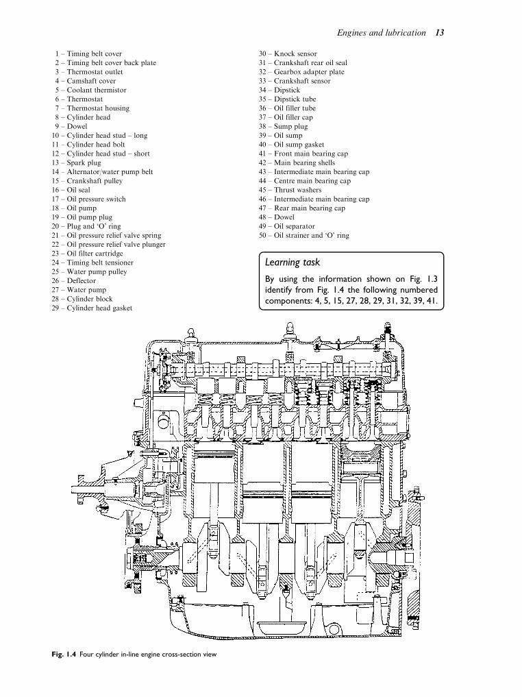
1 – Timing belt cover
2 – Timing belt cover back plate
3 – Thermostat outlet
4 – Camshaft cover
5 – Coolant thermistor
6 – Thermostat
7 – Thermostat housing
8 – Cylinder head
9 – Dowel
10 – Cylinder head stud – long
11 – Cylinder head bolt
12 – Cylinder head stud – short
13 – Spark plug
14 – Alternator/water pump belt
15 – Crankshaft pulley
16 – Oil seal
17 – Oil pressure switch
18 – Oil pump
19 – Oil pump plug
20 – Plug and ‘O’ ring
21 – Oil pressure relief valve spring
22 – Oil pressure relief valve plunger
23 – Oil filter cartridge
24 – Timing belt tensioner
25 – Water pump pulley
26 – Deflector
27 – Water pump
28 – Cylinder block
29 – Cylinder head gasket
30 – Knock sensor
31 – Crankshaft rear oil seal
32 – Gearbox adapter plate
33 – Crankshaft sensor
34 – Dipstick
35 – Dipstick tube
36 – Oil filler tube
37 – Oil filler cap
38 – Sump plug
39 – Oil sump
40 – Oil sump gasket
41 – Front main bearing cap
42 – Main bearing shells
43 – Intermediate main bearing cap
44 – Centre main bearing cap
45 – Thrust washers
46 – Intermediate main bearing cap
47 – Rear main bearing cap
48 – Dowel
49 – Oil separator
50 – Oil strainer and ‘O’ ring
Learning task
By using the information shown on Fig. 1.3
identify from Fig. 1.4 the following numbered
components: 4, 5, 15, 27, 28, 29, 31, 32, 39, 41.
Fig. 1.4 Four cylinder in-line engine cross-section view
Engines and lubrication 13
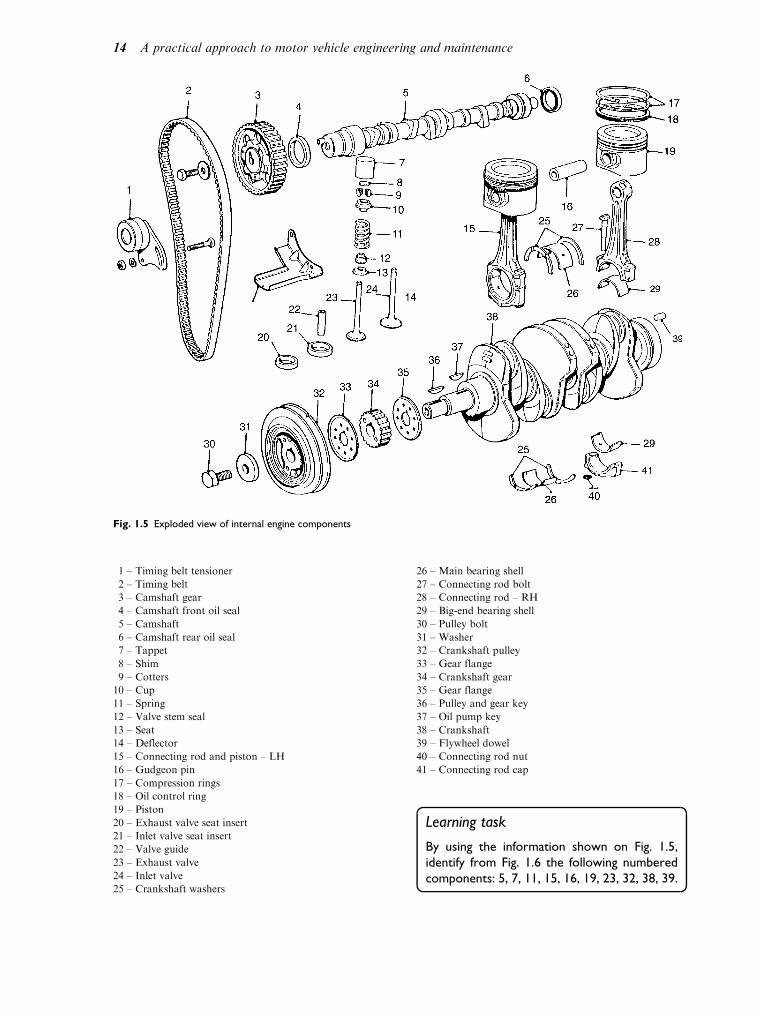
1 – Timing belt tensioner
2 – Timing belt
3 – Camshaft gear
4 – Camshaft front oil seal
5 – Camshaft
6 – Camshaft rear oil seal
7 – Tappet
8 – Shim
9 – Cotters
10 – Cup
11 – Spring
12 – Valve stem seal
13 – Seat
14 – Deflector
15 – Connecting rod and piston – LH
16 – Gudgeon pin
17 – Compression rings
18 – Oil control ring
19 – Piston
20 – Exhaust valve seat insert
21 – Inlet valve seat insert
22 – Valve guide
23 – Exhaust valve
24 – Inlet valve
25 – Crankshaft washers
26 – Main bearing shell
27 – Connecting rod bolt
28 – Connecting rod – RH
29 – Big-end bearing shell
30 – Pulley bolt
31 – Washer
32 – Crankshaft pulley
33 – Gear flange
34 – Crankshaft gear
35 – Gear flange
36 – Pulley and gear key
37 – Oil pump key
38 – Crankshaft
39 – Flywheel dowel
40 – Connecting rod nut
41 – Connecting rod cap
Learning task
By using the information shown on Fig. 1.5,
identify from Fig. 1.6 the following numbered
components: 5, 7, 11, 15, 16, 19, 23, 32, 38, 39.
Fig. 1.5 Exploded view of internal engine components
14 A practical approach to motor vehicle engineering and maintenance

1.4 Functionalrequirements of enginecomponents
These are shown in Table 1.1.
Learning tasks
1. Identify the properties of the main com-
ponents (what they are made of) from
the resources in the motor vehicle sec-
tion in the library. The main components
are: the cylinder head/block, pistons/
rings, crankshaft/bearings, inlet/exhaust
valves.
2. Give one advantage for the use of each
material.
1.5 Definition of termsused in motor vehicleengines
These are given in Table 1.2.
1.6 Cycles of operation
The basic function of an engine is to convertchemical energy (the fuel) into mechanicalenergy and to produce usable power and tor-que (this is the ability to turn the drivingwheels and move the vehicle). The spark igni-tion (SI) engine operates on the principle ofthe Otto four-stroke cycle or the Clerk two-stroke cycle of operations.
Fig. 1.6 Cross-sectioned view
Engines and lubrication 15

Table 1.1 Functional requirements of engine components
Component Function or purpose
Camshaft cover Encloses the camshaft and valve mechanism
Camshaft carrier Locates the camshaft and provides upper bearing locations
Camshaft Operates the valves and provides a means of driving the auxiliaries
Cylinder head Provides for (in some cases) the combustion space, inlet and exhaust gas ports, supports the valve gear
and part of the cooling system passages
Cam followers Provide a bearing surface between the rotating camshaft and valve stem
Collets Lock the valve spring to the valve
Valve spring Keeps the valves closed, but allows them to be opened when required
Valve Controls the flow of mixture into and out of the cylinder
Camshaft gear Provides the drive to the camshaft at half crankshaft speed
Tensioner Ensures the drive belt is maintained at a constant tension
Timing belt Transmits the drive from the crankshaft to the camshaft without slipping
Pistons Transmit the pressure of combustion down to the con-rod
Piston rings These form a gas- and oil-tight seal
Gudgeon pin Connects the piston to the con-rod
Connecting rod Connects the piston to the crankshaft and converts the straight line motion of the piston to the rotary
motion of the crankshaft
Crankshaft Transmits the power from all the cylinders to the flywheel and transmission
Shell bearings These form the bearing surface for the crankshaft journals
Table 1.2 Definitions of motor vehicle engine terms
Term Definition
OHV Over head valve
OHC Over head camshaft
TDC Top dead centre
BTDC Before top dead centre
ATDC After top dead centre
BDC Bottom dead centre
BBDC Before bottom dead centre
ABDC After bottom dead centre
Bore Diameter of the cylinder
Stroke Distance moved by piston from TDC to BDC
Cylinder capacity Stroke of the piston multiplied by the cross-sectional area of the bore
Swept volume (SV) Volume created by the area of the bore times the stroke
Clearance volume (CV) Volume left by piston when at TDC
Compression ratio (CR) Ratio of swept volume (SV) and clearance volume (CV) against clearance volume (CV). This is
expressed asðSVþ CVÞ
CVEngine capacity Capacity of all the cylinders
IVO Inlet valve opens
IVC Inlet valve closes
EVO Exhaust valve opens
EVC Exhaust valve closes
Valve lead The amount in crankshaft degrees the valves open before TDC or BDC
Valve lag The amount in crankshaft degrees the valves close after TDC or BDC
Valve overlap The amount in degrees the valves are open together measured at TDC
Valve timing The point at which the valves should open in relation to piston/crankshaft movement
Valve clearance The distance between the camshaft and valve stem, allows the valve to close
Ignition timing The time at which the distributor opens the points in relation to the pistons
Combustion This is the burning of the petrol and air mixture in the cylinder
Energy Capacity for doing work
Power Rate of doing work
16 A practical approach to motor vehicle engineering and maintenance

Four-stroke cycle of operations
To complete the cycle of operations, fourstrokes of the piston are used. This involvestwo complete revolutions of the crankshaft,the inlet and exhaust valves being mechanic-ally opened and closed at the correct times.Starting with the piston at TDC and thecrankshaft rotating clockwise (looking fromthe front of the engine), the strokes operateas follows.
First stroke
With the inlet valve open and the exhaustvalve closed the piston moves in a downwardsdirection drawing in a mixture of petrolvapour and air. This is called the induction
stroke.
Second stroke
The piston moves up with both valves closed,thus compressing the mixture into the combus-tion chamber at the top of the cylinder. This isthe compression stroke.
Third stroke
At the end of the compression stroke a sparkoccurs at the sparking plug. This ignites themixture which burns very rapidly heating thegas to a very high temperature which also raisesits pressure. This forces the piston down thecylinder and is called the power stroke.
Fourth stroke
As the piston begins to rise the exhaust valveopens and the spent gases are forced out of thecylinder. This is called the exhaust stroke. At theend of this stroke the exhaust valve closes andthe inlet valve opens.
This cycle of induction, compression,power and exhaust operates on a continuousbasis all the time the engine is running. Ascan be seen the complete cycle of operationsof a four-stroke engine occupies two completerevolutions of the crankshaft. The SI enginedraws into the cylinder a mixture of petroland air which is compressed and burnt. TheCI engine draws air only into the cylinderwhich is compressed to a very high pressure.This also raises its temperature and when fuelis sprayed into the combustion chamber itself-ignites. The four-stroke cycle is illustratedin Fig. 1.7.
Learning task
Read about the diesel four-stroke engine and
describe in your own words the cycle of
operations.
Two-stroke cycle of operations
By using both sides of the piston the fourphases (induction, compression, power, andexhaust) are completed in two strokes of thepiston and one revolution of the crankshaft.No valves are used as ports in the cylinder arecovered and uncovered by the piston as itmoves up and down the cylinder. Whendescribing how this type of engine works it isbest to look at what is happening above thepiston and then below the piston.
First stroke (piston moving downthe cylinder)
Events above the piston
The expanding gases which have been ignitedby the spark plug force the piston down thecylinder. About two-thirds of the way downthe exhaust port is uncovered and the burninggases leave the cylinder. As the piston con-tinues to move downwards, the transfer port
is uncovered; this allows a fresh mixture intothe cylinder.
Events below the piston
The decending piston covers the inlet port.The air and fuel trapped in the crankcase iscompressed.
Second stroke (piston moving upthe cylinder)
Events above the piston
The transfer port is closed first, quickly fol-lowed by the closing of the exhaust port.Further movement of the piston compressesthe mixture now trapped in the upper part ofthe cylinder.
Events below the piston
As the piston moves upwards, the depressioncreated in the crankcase draws a fresh mixturein through the inlet port as it is uncovered by thepiston.
The two-stroke cycle is shown in Fig. 1.8.
Engines and lubrication 17

Two-stroke compression ignitionengine
First stroke (piston moving upwards)
The cylinder is filled with air under pressurefrom the pressure charger. The piston rises cov-ering the inlet ports; the exhaust valves are alsoclosed. The air is compressed and fuel is sprayed
into the cylinder. It mixes rapidly with the airuntil self-ignition occurs near TDC.
Second stroke (piston movingdownwards)
The rapidly expanding gases force the pistondownwards. The exhaust valves are arranged
Fig. 1.7 The four-stroke cycle of operations
18 A practical approach to motor vehicle engineering and maintenance

to open just before the piston uncovers the inletports. A new charge of air is forced into thecylinder through the open inlet ports forcingthe spent gases out of the open exhaust valvesand filling the cylinder with a fresh charge of air.
With the diesel two-stroke it is necessary topressure charge the engine as there is no actualinduction stroke. With the short port-openingperiod it is essential to fill the cylinder with a largemass of air to create the compression pressure andtemperature rise to self-ignite the fuel when it isinjected. This gives the following advantages:
. high power-to-weight ratio
. higher engine speeds
. simpler in construction
. good scavenging of exhaust gases
Its main disadvantages are:
. higher fuel consumption
. lower volumetric efficiency
. less complete combustion
. good scavenging of exhaust gases
Figure 1.9 shows the two-stroke CI engine.
Exhaustport
Transferport
Transfer and exhaust piston at BDC Both ports closed piston rising on compression
Piston fallingexhaust opentransfer port open.Mixture transferredfrom crankcase.
Inletport
Compression abovepiston
Piston risinginduction intocrankase
Fig. 1.8 The two-stroke cycle of operations
Airin
Compressor
Valve openExhaust
Exhaust outAir in
Fuel injector
Compressor
Power and combustionstroke
Fig. 1.9 Cross-section of a two-stroke diesel engine
Engines and lubrication 19
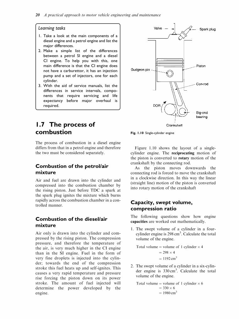
Learning tasks
1. Take a look at the main components of a
diesel engine and a petrol engine and list the
major differences.
2. Make a simple list of the differences
between a petrol SI engine and a diesel
CI engine. To help you with this, one
main difference is that the CI engine does
not have a carburettor, it has an injection
pump and a set of injectors, one for each
cylinder.
3. With the aid of service manuals, list the
differences in service intervals, compo-
nents that require servicing and life
expectancy before major overhaul is
required.
1.7 The process ofcombustion
The process of combustion in a diesel enginediffers from that in a petrol engine and thereforethe two must be considered separately.
Combustion of the petrol/airmixture
Air and fuel are drawn into the cylinder andcompressed into the combustion chamber bythe rising piston. Just before TDC a spark atthe spark plug ignites the mixture which burnsrapidly across the combustion chamber in a con-trolled manner.
Combustion of the diesel/airmixture
Air only is drawn into the cylinder and com-pressed by the rising piston. The compressionpressure, and therefore the temperature ofthe air, is very much higher in the CI enginethan in the SI engine. Fuel in the form ofvery fine droplets is injected into the cylin-der; towards the end of the compressionstroke this fuel heats up and self-ignites. Thiscauses a very rapid temperature and pressurerise forcing the piston down on its powerstroke. The amount of fuel injected willdetermine the power developed by theengine.
Figure 1.10 shows the layout of a single-cylinder engine. The reciprocating motion ofthe piston is converted to rotary motion of thecrankshaft by the connecting rod.
As the piston moves downwards theconnecting rod is forced to move the crankshaftin a clockwise direction. In this way the linear(straight line) motion of the piston is convertedinto rotary motion of the crankshaft
Capacity, swept volume,compression ratio
The following questions show how enginecapacities are worked out mathematically.
1. The swept volume of a cylinder in a four-cylinder engine is 298 cm3. Calculate the totalvolume of the engine.
Total volume ¼ volume of 1 cylinder 4
¼ 298 4
¼ 1192 cm3
2. The swept volume of a cylinder in a six-cylin-der engine is 330 cm3. Calculate the totalvolume of the engine.
Total volume ¼ volume of 1 cylinder 6¼ 330 6
¼ 1980 cm3
Fig. 1.10 Single-cylinder engine
20 A practical approach to motor vehicle engineering and maintenance

3. The total volume of a four-cylinder engine is1498 cm3. Calculate the swept volume of onecylinder.
Volume of 1 cylinder ¼ total volume4
¼ 14984
¼ 374:5 cm3
4. The cross-sectional area (CSA) of the pistoncrown is 48:5 cm2 and the stroke is 12 cm. Cal-culate the swept volume of the cylinder and thecapacity of the engine if it has six cylinders.
Swept volume ¼ CSA length of stroke
¼ 48:5 12
¼ 582 cm3
Capacity ¼ SV no. of cylinders
¼ 582 6
¼ 3492 cm3
Learning tasks
1. Calculate the SV of an engine in the workshop
by removing a cylinder head and measuring the
bore diameter and stroke. Check your results
by looking in the manufacturer’s manual.
2. What advantages are there to having an
over-size cylinder (the diameter of the cylin-
der larger than the stroke)?
3. What are the constructional differences
between the combustion chamber of an SI
engine and a direct injection Cl engine?
4. What safety aspects should be observed
when working with petrol or diesel?
1.8 Cylinder arrangementsand firing orders
There are three arrangements which may beused for an engine.
. In-line engine The cylinders are arranged in asingle row, one behind the other. They may bevertical, as in most modern light vehicles, hor-izontal as used in coaches where the engine ispositioned under the floor, or inclined at anangle to allow for a lower bonnet line.
. Vee engine The cylinders are arranged in tworows at an angle to one another. The angle fortwo-, four- and eight-cylinder engines is usually90. For six- and twelve-cylinder engines the
angle is usually 60. This is illustrated inFig. 1.11.
. Opposed piston or cylinder engine This iswhere the cylinders are at an angle of 180
apart and usually positioned horizontally(see Fig. 1.12).
Learning task
Take a look at each type of engine and draw up
a simple list of the main advantages and disad-
vantages, e.g. is it easier to work on for the
mechanic? Does it allow for a lower bonnet line?
Is the exhaust system easier to arrange? If so,
what advantage/disadvantage is there in this?
Fig. 1.11 A high-performance V eight-cylinder engine
Fig. 1.12 Horizontally opposed cylinders with divided crankcase
Engines and lubrication 21

Firing orders
When considering multi-cylinder engines andfiring orders, the power strokes should bespaced at equal intervals to give the smooth-est possible running of the engine. Each inter-val is equal to the number of degrees percycle of operation. This will be 720 for afour-stroke engine. This is then divided bythe number of cylinders, e.g. 720=4 ¼ 180.Therefore the firing interval for a four-cylinder in-line engine will be 180 and thatfor a six-cylinder in-line engine will be720=6 ¼ 120. The firing order is determinedby two things.
. The position of the cylinders and the crankson the crankshaft (this determines the possiblefiring orders).
. The arrangement of the cams on the camshaft(this must be in accordance with one of thepossible firing orders).
The arrangements on the crankshaft are suchthat the pistons on a four-cylinder in-line engineare moved in pairs, e.g. numbers 1 and 4 formone pair and 2 and 3 form the other pair. Thismeans that when number 1 is moving down, onits power stroke, number 4 will also be movingdown, but on its induction stroke. Dependingon the firing order, when number 2 pistonmoves upwards it will either be on its exhaustor compression stroke, number 3 will be on itscompression or exhaust stroke.
From this then we can see that there are twopossible firing orders for a four-cylinder in-lineengine. These are 1342 or 1243, both of whichare in common use today. Table 1.3 belowshows the events in each of the cylinders forthe two firing orders. The reasons for usingmore than one cylinder are very complex butin simple terms they are as follows.
. A multi-cylinder engine has a higher power-to-weight ratio than a single-cylinder engine.
. With multi-cylinder engines there are morepower strokes for the same number of enginerevolutions. This gives fewer fluctuations intorque and a smoother power output.
. A better acceleration is achieved due to smal-ler moving parts and more firing impulses.
. The crankshaft is balanced better; the crank-shaft of a single-cylinder engine cannot beperfectly balanced. Very good balance isobtained with six or more cylinders.
. The piston crown cannot be adequatelycooled on large single-cylinder engines; asthe piston gets larger the centre of the crownbecomes more difficult to keep cool.
Figure 1.13 shows firing orders for a range ofdifferent engines.
Speed relationship betweencrankshaft and camshaft
The movement ratio between the crankshaftand the camshaft is always 2:1 on all four-stroke engines. This can be simply determinedeither by counting the number of teeth on eachgear or by measuring the diameter of the gearsand dividing the driven gear by the drivinggear. From this it will be seen thatthe camshaft gear is always twice as large asthe crankshaft gear.
Learning task
Describe two methods you could use to deter-
mine the TDC position of number I cylinder on
its firing stroke.
Cylinder arrangements
In-line cylinders
The four-cylinder in-line is the most populardesign in Europe. It has the advantages of havingeasy access for its size and providing enoughpower for most applications. The larger six-cylin-der engines provide for better acceleration andgive better engine balance, and smoother running.
Horizontally opposed cylinders
In this layout the engine has little second-ary imbalance giving very smooth runningand long engine life. It also has a lower centreof gravity allowing for a lower bonnet line.
Table 1.3 Firing orders: 1342 and 1243
Cylinder
number 1 2 3 4
1st Stroke I I C E E C P P
2nd Stroke C C P I I P E E
3rd Stroke P P E C C E I I
4th Stroke E E I P P I C C
P – Power; I – Induction; E – Exhaust; C – Compression
22 A practical approach to motor vehicle engineering and maintenance

Vee cylinder arrangements
With this layout the engine is more compact thanan in-line engine of the same number of cylindersand the vee 6, 8 and 12 are well balanced.
1.9 Valve-timing diagrams
The valve timing of an engine is set to give thebest possible performance. This means that the
Fig. 1.13 Firing order diagrams for different engines
Engines and lubrication 23
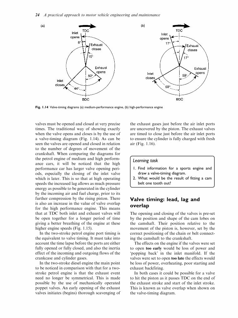
valves must be opened and closed at very precisetimes. The traditional way of showing exactlywhen the valve opens and closes is by the use ofa valve-timing diagram (Fig. 1.14). As can beseen the valves are opened and closed in relationto the number of degrees of movement of thecrankshaft. When comparing the diagrams forthe petrol engine of medium and high perform-ance cars, it will be noticed that the highperformance car has larger valve opening peri-ods, especially the closing of the inlet valvewhich is later. This is so that at high operatingspeeds the increased lag allows as much pressureenergy as possible to be generated in the cylinderby the incoming air and fuel charge, prior to itsfurther compression by the rising piston. Thereis also an increase in the value of valve overlapfor the high performance engine. This meansthat at TDC both inlet and exhaust valves willbe open together for a longer period of timegiving a better breathing of the engine at thesehigher engine speeds (Fig. 1.15).
In the two-stroke petrol engine port timing isthe equivalent to valve timing. It must take intoaccount the time lapse before the ports are eitherfully opened or fully closed, and also the inertiaeffect of the incoming and outgoing flows of thecrankcase and cylinder gases.
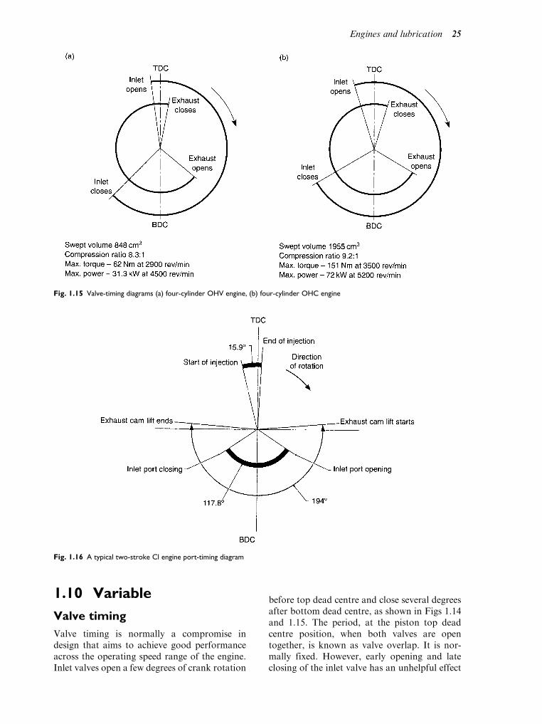
In the two-stroke diesel engine the main pointto be noticed in comparison with that for a two-stroke petrol engine is that the exhaust eventneed no longer be symmetrical. This is madepossible by the use of mechanically operatedpoppet valves. An early opening of the exhaustvalves initiates (begins) thorough scavenging of
the exhaust gases just before the air inlet portsare uncovered by the piston. The exhaust valvesare timed to close just before the air inlet portsto ensure the cylinder is fully charged with freshair (Fig. 1.16).
Learning task
1. Find information for a sports engine and
draw a valve-timing diagram.
2. What would be the result of fitting a cam
belt one tooth out?
Valve timing: lead, lag andoverlap
The opening and closing of the valves is pre-setby the position and shape of the cam lobes onthe camshaft. Their position relative to themovement of the piston is, however, set by thecorrect positioning of the chain or belt connect-ing the camshaft to the crankshaft.
The effects on the engine if the valves were setto open too early would be loss of power and‘popping back’ in the inlet manifold. If thevalves were set to open too late the effects wouldbe loss of power, overheating, poor starting andexhaust backfiring.
In both cases it could be possible for a valveto hit the piston as it passes TDC on the end ofthe exhaust stroke and start of the inlet stroke.This is known as valve overlap when shown onthe valve-timing diagram.
Fig. 1.14 Valve-timing diagrams (a) medium-performance engine, (b) high-performance engine
24 A practical approach to motor vehicle engineering and maintenance
1.10 Variable
Valve timing
Valve timing is normally a compromise indesign that aims to achieve good performanceacross the operating speed range of the engine.Inlet valves open a few degrees of crank rotation
before top dead centre and close several degreesafter bottom dead centre, as shown in Figs 1.14and 1.15. The period, at the piston top deadcentre position, when both valves are opentogether, is known as valve overlap. It is nor-mally fixed. However, early opening and lateclosing of the inlet valve has an unhelpful effect
Fig. 1.15 Valve-timing diagrams (a) four-cylinder OHV engine, (b) four-cylinder OHC engine
Fig. 1.16 A typical two-stroke Cl engine port-timing diagram
Engines and lubrication 25
on low engine speed emissions and design devel-opments, such as variable valve timing, havebeen introduced to improve emissions and otheraspects of engine performance.
Variable valve timing
Variable valve timing is a development that hasbeen enabled by the use of electronic controlwhich permits valve timing to be changed whilethe engine is operating, to suit low speed, inter-mediate speed and high speed operation. Thevariations in inlet valve timing are approxi-mately as follows:
. Low speed – inlet valves opened later toimprove idling performance;
. Intermediate speed – inlet valves opened a fewdegrees earlier to take advantage of manifolddesign and thus improve cylinder filling andperformance;
. High speed – a larger degree of early openingof the inlet valves.
The amount of variation in the timing may belimited to approximately 10
The aim of the system is to reduce harm-ful exhaust emissions and improve engineperformance.
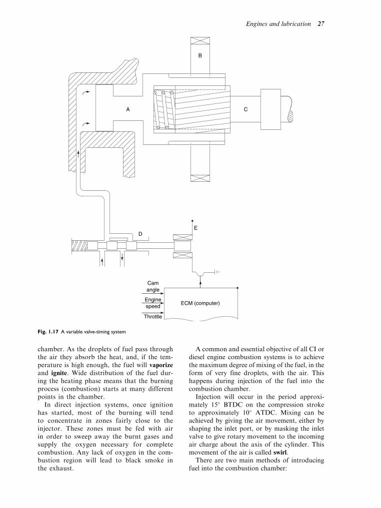
Operation of a variable valvetiming system
Helical spline inside hydraulic piston
Figure 1.17 shows the elements of a mechanical/hydraulic device that provides a means of vary-ing valve timing. The drive end of the camshaftC is equipped with external splines that form ahelical thread. Surrounding this helical splinedportion of the camshaft is a hydraulically oper-ated control piston A. The hollow interior ofthis control piston is splined to fit over thecorresponding splines on the camshaft. Theexterior of the control piston is also splined sothat it can slide axially inside the camshaft drivegear B. Axial movement of the control piston A,relative to the camshaft, will cause the camshaftto rotate by a few degrees relative to the direc-tion of rotation of the camshaft, thus advancingor retarding inlet valve opening. Control of thehydraulic pressure applied to the piston A isachieved by computer control of the solenoidoperated valve D. Oil pressure is generated bythe main engine oil pump and when pressure isreleased from the hydraulic piston the oil is
returned to the sump via the control valve.Because the cam profile is constant, this typeof device serves to change valve opening andclosing times but the valve period (anglebetween inlet valve opening and closing)remains constant.
Other variable valve-timing systems currentlyin use also rely on similar technology. One typeprovides camshaft rotation by means of ahydraulically operated paddle arrangement onthe camshaft which means that the valve open-ing and closing is advanced or retarded and thevalve period remains constant. Another typehas separate cams for low and high speed opera-tion and hydraulically operated mechanismeffects the change from one set of cams to theother, by computer control, while the engine isoperating.
Ignition timing
Correct setting of the ignition timing is vitallyimportant, and, as described earlier, ignitiontakes place as the piston nears TDC towardsthe end of the compression stroke. Accuracy isnecessary to gain the best power output andeconomy from an engine.
1.11 Combustion in apetrol engine
As the piston reaches TDC the fuel is ignitedby the spark at the spark plug and the burn-ing process of the mixture begins. As thegases rapidly expand the piston is forceddown the cylinder on the power stroke. Thespeed of the flame front must not exceedthe speed of the power stoke. Figure 1.18shows the combustion process occurring ina wedge-shaped combustion chamber of apetrol engine.
1.12 Combustion in adiesel engine
Combustion in a petrol engine originates(begins) at the spark plug and then progressesacross the combustion chamber in a con-trolled manner. In the case of the dieselengine, combustion of the fuel is initiated(started) by the heat of the air in the
26 A practical approach to motor vehicle engineering and maintenance
chamber. As the droplets of fuel pass throughthe air they absorb the heat, and, if the tem-perature is high enough, the fuel will vaporizeand ignite. Wide distribution of the fuel dur-ing the heating phase means that the burningprocess (combustion) starts at many differentpoints in the chamber.
In direct injection systems, once ignitionhas started, most of the burning will tendto concentrate in zones fairly close to theinjector. These zones must be fed with airin order to sweep away the burnt gases andsupply the oxygen necessary for completecombustion. Any lack of oxygen in the com-bustion region will lead to black smoke inthe exhaust.
A common and essential objective of all CI ordiesel engine combustion systems is to achievethe maximum degree of mixing of the fuel, in theform of very fine droplets, with the air. Thishappens during injection of the fuel into thecombustion chamber.
Injection will occur in the period approxi-mately 15 BTDC on the compression stroketo approximately 10 ATDC. Mixing can beachieved by giving the air movement, either byshaping the inlet port, or by masking the inletvalve to give rotary movement to the incomingair charge about the axis of the cylinder. Thismovement of the air is called swirl.
There are two main methods of introducingfuel into the combustion chamber:
Camangle
A C
B
ED
ECM (computer)Enginespeed
Throttle
Fig. 1.17 A variable valve-timing system
Engines and lubrication 27

. direct, and
. indirect.
Direct injection
In the ‘direct injection’ system (Fig. 1.19) thefuel is injected directly into the combustionchamber which is formed in the piston crown.The air is made to rotate in this cavity at 90 tothe incoming swirl by the squeezing out of theair from between the cylinder head face and thepiston crown as the piston approaches the endof its compression stroke. This rapid movementof the air is called turbulence.
Maximum cylinder pressures are high, caus-ing diesel knock, rough running and higherexhaust smoke. However, easier starting, nostarting aids, high thermal efficiency andfairly constant torque output are the main
advantages. Also, because of the low surfacearea/volume ratio giving low heat losses, a char-acteristic of the system is a considerable savingin fuel giving good fuel consumption results. Adisadvantage is a reduction in volumetric effi-ciency, due to the necessity of giving the incom-ing air the swirling movement as it passes intothe cylinder. This effect can be largely overcomeby the use of the ‘indirect injection’ system.
Indirect injection
In this arrangement the required movement ofthe air is made by transferring it, towards theend of the compression stroke, from the cylin-der space into a small chamber (usually locatedin the cylinder head) via a restricting throat,arranged so as to give rapid rotation of the airin the chamber. The fuel is injected into thechamber at a point where the passage of airpast the tip of the injector will give the max-imum degree of mixing. This is shown inFig. 1.20.
1.13 Phases of combustion
There are three distinct periods or phases.
First phase – ignition delayperiod
This is the time taken between the start of theinjection of the fuel to the commencement ofcombustion. During this important period, theinjected fuel particles are being heated by thehot air to the temperature required by the fuelto self-ignite.
Fig. 1.18 Combustion zones in a wedge-shaped combustion
chamber
Fig. 1.19 Direct injection
Fig. 1.20 Indirect injection
28 A practical approach to motor vehicle engineering and maintenance
Second phase – pressure rise orflame spread
The flame spread causes a sharp pressure risedue to the sudden combustion of the fuel thatwas injected during the first phase. The rate ofpressure rise governs the extent of the combus-tion knock (diesel knock).
Third phase – direct orcontrolled burning
Direct burning of the fuel as it enters thechamber gives a more gradual pressurerise. The rate of combustion during thisphase is directly controlled by the quantityof fuel injected into the cylinder. Combus-tion and expansion of the gases takes placeas the piston descends on its power strokeproducing a sustained torque on thecrankshaft during the time the gases areburning.
Learning tasks
1. From what you have learned so far describe
in your own words the main differences
between combustion in a petrol engine and
combustion in a diesel engine.
2. Examine the combustion chamber of a
direct injection engine and make a sketch
of the main components, e.g. piston posi-
tioned in the cylinder at TDC, the inlet and
exhaust valves positioned in the cylinder
head.
1.14 The maincomponents used inthe construction of theengine
Camshafts
As we have seen, the function of the camshaftis to open the valves at the correct time in thecycle of operations of the engine. It is alsoused as a drive for various auxiliary unitssuch as the distributor, fuel pump and oilpump.
The position of the camshaft can be in thecylinder block (often termed as side-mounted).The main advantage of this arrangement is
that the timing is not disturbed when thecylinder head is removed. An alternative pos-ition is on the top of the cylinder head (termedthe over head cam or OHC). This has theadvantage of there being a considerable reduc-tion in components that are required to trans-mit the movement of the camshaft to open thevalves.
Figure 1.21 shows a typical camshaft for afour-cylinder engine. The camshaft drivinggear or sprocket is located on the shaft bymeans of a woodruff key or dowel peg toensure correct fitting, and therefore correcttiming, and to give a positive location of thedriving gear (see Fig. 1.22).
Camshaft drives
Several methods are employed to transmit thedrive from the crankshaft to the camshaft, theseare chain, gear and toothed belt (Fig. 1.23). Themost common one in use on modern OHCengines is the toothed belt drive. This has theadvantages of being silent in operation, requir-ing no lubrication and being fairly easy toremove and replace.
Learning tasks
1. From the manuals of over head camshaft
engines, make a simple sketch of how the
camshaft and crankshaft timing marks
should be lined up.
2. When next in the workshop remove the
timing belt from an engine. Rotate the crank
shaft and re-align the timing marks, replace
the belt and apply the correct tension.
Valves
Inlet valve
This is made from high tensile alloy steels,e.g. those containing nickel, chromium andmolybdenum.
Exhaust valve
This is also made from high tensile alloy steels,for example, those containing alloys of cobaltchromium and silicon chromium, silicon chro-mium austenitic steel, all of which resist oxida-tion, corrosion and wear. Under full power itcan reach temperatures of around 650 C. Forextreme operating conditions the valve stem is
Engines and lubrication 29

made hollow and partly filled with sodium,which is a very soft metal having a meltingpoint of approximately 98 C. Under runningconditions it is molten, and in splashing fromend to end of the valve stem it assists the
transfer of heat from the hot valve head tothe valve stem.
Several types of valve have been used in thepast and are to be found in current productionengines. The most common are the poppet valveon the four-stroke engine as shown in Fig. 1.5and the reed valve on the two-stroke motor cycleengine. The other types to have been tried arethe rotary valve and the sleeve valve.
Valve stem seals
Because a clearance is necessary between thevalve stem and the guide, valve stem seals arefitted to prevent excessive oil from passing downthe stem and into the combustion chamber orexhaust manifold. They are most commonlyfitted on the inlet valves as this is on the suctionside of the combustion chamber and the oil ismore readily drawn into the cylinder. As it isburnt it causes blue smoke to be passed out ofthe exhaust into the atmosphere. See Fig. 1.25(a).
Valve springs
The purpose of the valve spring is to close thevalve. They also prevent the valve from
Fig. 1.21 The camshaft. The shape of a camshaft lobe is designed to give required performance with least strain on valve gear
Fig. 1.22 Location of camshaft sprocket
30 A practical approach to motor vehicle engineering and maintenance

Fig. 1.23 Camshaft drives (a) chain driven, (b) gear driven, (c) toothed belt
Engines and lubrication 31

bouncing open at the wrong time in the enginecycle (Fig. 1.24). Always fit close coils towardsthe valve head. The springs are made from eitherplain high-carbon steel or a low alloychromium-vanadium steel.
Valve guides
These are usually made of cast iron and are apress fit in the cylinder head, although bronze issometimes used, particularly for exhaust valves,because of its better heat conducting properties.If the cylinder head is made of cast iron then theguide will be part of the same casting.
Operation of the valves
A number of different methods are used to openand close the valves, the most common methodsare:
. pushrod and rocker used where the camshaft ispositioned in the cylinder block;
. rocker, lever or finger used on OHCengines;
. direct acting used where the camshaft actsdirectly on the tappet;
. hydraulic operation used where the valveclearance is automatically taken up duringnormal running of the engine.
These are shown in Figs. 1.25(a)–(c) and Fig.1.26.
Valve clearance and adjustment
A number of methods are used to position thecamshaft so that the valve clearance can becorrectly set. The follower must be resting onthe lowest part of the cam profile, i.e. the base ofthe cam, before any adjustment can take place.To determine this position one of the followingmethods may be used.
. Turn the engine until the valve to be adjustedis fully open and rotate the crankshaft afurther complete turn. The follower will nowbe on the lowest part of the cam and theclearance can be correctly set.
. The ‘rocking method’ is a quicker way ofsetting the valve clearances although it is notquite so accurate. Rotate the engine until thevalves on number four cylinder are justchanging over, i.e. the exhaust valve is justclosing and the inlet valve is just opening.Numbers one and four pistons will now beat TDC, the valves on number one cylinderwill be fully closed and can therefore beadjusted. To adjust the valve on number fourcylinder rotate the engine one full turn (360).The same method can be used to set numberstwo and three cylinders.
. The ‘rule of nine’ can also be used. Numberthe valves from the front of the engine oneto eight. Rotate the crankshaft until numberone valve is fully open; number eight valvewill be fully closed and can therefore beadjusted, 1þ 8 ¼ 9. In this way if the num-bers are made to add up to nine the valvescan be accurately set using the followingmethod:
number 1 valve fully open, set number 8 1þ 8 ¼ 9
number 2 valve fully open, set number 7 2þ 7 ¼ 9
number 3 valve fully open, set number 6 3þ 6 ¼ 9
number 4 valve fully open, set number 5 4þ 5 ¼ 9
number 5 valve fully open, set number 4 5þ 4 ¼ 9
number 6 valve fully open, set number 3 6þ 3 ¼ 9
number 7 valve fully open, set number 2 7þ 2 ¼ 9
number 8 valve fully open, set number 1 8þ 1 ¼ 9
The above three methods can only be usedon four-cylinder, four-stroke, in-line engines.For other layouts and cylinder arrangements,reference will need to be made to the manu-facturer’s manual to give the correct procedureto follow.
Hydraulic tappet operation
When the valve is closed, oil from the enginelubrication system passes through a port inthe tappet body, through four grooves in theplunger and into the cylinder feed chamber.From the feed chamber the oil flows througha non-return valve (ball type) into the pres-sure chamber (A in Fig. 1.26).
The load of the cylinder spring enables theplunger to press the rocker arm against thevalve, eliminating any free play.
Fig. 1.24 Valve springs
32 A practical approach to motor vehicle engineering and maintenance

As the cam lifts the follower the pressure inthe pressure chamber rises, causing the non-return valve to close the port feed chamber. Sincethe oil cannot be compressed it forms a rigidconnection between the tappet body, cylinderand plunger so that these parts rise together toopen the valve.
The clearance between the tappet body andthe cylinder is accurately controlled to allow a
specific amount of oil to escape from the pres-sure chamber. Oil will only pass along the cylin-der bore when the pressure is high during valveopening. After the valve has closed, this loss ofoil will produce a small amount of free play; andalso there will not be any pressure available inthe pressure chamber. Oil from the feed cham-ber can then flow through the non-return valveinto the pressure chamber so that the tappet
Fig. 1.25 (a) A typical OHV assembly, (b) Direct acting type, (c) Push rod valve operation
Engines and lubrication 33

cylinder can be raised by the pressure of thespring to eliminate the play in the system beforethe valve is operated again.
The amount of oil flowing into the pressurechamber will be slightly more than the amountof oil lost when the tappet has to expand due tothe increased play (wear). When the tappet hasto be compressed due to the expansion of thevalve slightly less than the amount of oil lost willflow into the pressure chamber.
Note: If the engine is started up after standing
unused for a lengthy period of time a chattering
noise may be heard from the valve operating
system. This is normal and will disappear after a
few seconds when the tappets are pressurized
with oil.
Cylinder head
Function
This forms the cover that is fitted on the topof the cylinder block. It may contain thecombustion chamber which is formed in the
space remaining when the piston reaches thetop of its stroke. On some designs this spaceis formed in the top of the piston and thecylinder head is flat. The head will also con-tain the spark plugs, inlet and exhaust valvestogether with their operating mechanism, anumber of ports which allow gases into andout of the cylinders, bolt holes to enablecomponents to be bolted to the head andthe head to be attached to the cylinder block.It may also contain part of a water jacketwhich forms part of the cooling system. Thematerials from which the cylinder head ismade are often the same as the cylinderblock, e.g. cast iron or aluminium. The cylin-der head is illustrated in Fig. 1.27.
Cylinder head tightening sequence
To avoid distorting either the cylinder head orthe head gasket the tightening sequence (order)must be followed. The torque settings mustalso be correct to prevent over-stretching of
Fig. 1.26 Hydraulic valve tappet assembly – sectional view
34 A practical approach to motor vehicle engineering and maintenance

Fig. 1.27 Cylinder head – exploded view
Engines and lubrication 35

the bolts and studs or stripping of the threads.The manufacture’s manual must always bereferred to and the procedure followed; thiswill ensure that the above problems are notencountered when reassembling the cylinderhead to the engine. In some cases it may benecessary to fit new bolts or nuts as thesebecome stretched and cannot be used a secondtime. Figure 1.28 shows a typical tighteningsequence.
Learning tasks
1. Why is the inlet valve larger in diameter
than the exhaust valve?
2. What are the reasons for using hydraulic
tappets?
3. Under what circumstances would it be
necessary to decoke a cylinder head? Name
any special tools or equipment that you
would use.
4. Give the correct procedure for checking
and adjusting the valve clearances for an
OHC engine.
5. How would you check the serviceability of
the valves and their seats?
6. When refitting the cylinder head, why is it
necessary to tighten the bolts/nuts in the
correct sequence? What would happen if
this sequence was not followed?
7. Why is it necessary to have a gap between
the valve stem and operating mechanism?
What would happen if the engine was oper-
ated with no valve clearance?
8. Remove and refit a cylinder head from an
engine, make out a job sheet and record any
special tools used, faults found and safety
procedures that were followed. Draw up
an operations schedule for the task.
Piston
The main function of the piston is to provide themovable end of the cylinder, so as to convert theexpansion of the burning gases on the powerstroke into mechanical movement of the piston,connecting rod and crankshaft. On some typesof engines the piston crown is designed to aspecific shape instead of being flat. This allowsfor the shape of the combustion chamber to beincluded in the piston crown instead of in thecylinder head, and may also have an effect onthe flow of gases into and out of the cylinder.Figure 1.29 shows an example of the shape ofthe combustion chamber being included in thepiston crown.
Piston skirt
Several shapes are used in the manufacture of thelower part of the piston, called the piston skirt, e.g.
. Solid skirt used in both CI and SI high speedengines, where heavy loadings may be placedon the piston;
. Split skirt where small clearances are used toreduce piston slap when the engine is cold;
. Slipper type which is used to reduce the weightof the piston by cutting away the bottom of thenon-thrust sides of the piston skirt; at the sametime it reduces the area in contact with thecylinder wall, and also allows for a reductionin the overall height of the engine as BDC isnow closer to the crankshaft.
A piston skirt is illustrated in Fig. 1.30. Whencold, the piston head is smaller in diameter thanthe skirt. When the engine is operating at itsnormal temperature the piston head expandsmore than the skirt due to its being closer to
Fig. 1.28 Cylinder head bolt tightening sequence Fig. 1.29 Combustion chambers
36 A practical approach to motor vehicle engineering and maintenance

the very hot gases and also the fact that there isa greater volume of metal at this point.
Piston rings
The piston ring (Fig. 1.31) seals the gap leftbetween the piston and the cylinder wall. Madefrom high-grade centrifugally cast iron, it issplit to enable the ring to be assembled ontothe piston. Some rings may be coated on theirouter edge with chromium to give better wearcharacteristics and longer life. Normally threerings are fitted. The top compression ring takesmost of the compression pressure and formsthe first defence against the heat and escapinggases. It may be stepped so that it misses theridge that tends to form in the cylinder bore atTDC. The second is also a compression ringthat completes the sealing against compressionloss. The third ring is the oil control ring. It isthis ring that removes the excess oil from thecylinder wall, passing it back to the sumpthrough holes drilled in the oil control ringgroove of the piston. This ring may be madeup from a number of steel rails that haveradiused chromium plated edges. A crimpedspring fitted in the ring groove next to thepiston expands the rails against the cylinderwall. This type are commonly fitted where thepiston comes very close to the oil in the sump,
i.e. short stroke engines, or where some wearhas taken place in the cylinder bore but notenough to warrant reboring the engine andfitting new pistons and rings.
Connecting rod
The con-rod connects the piston to the crank-shaft. Its action converts the linear (straightline) movement of the piston into the rotarymovement of the crankshaft. It is attached tothe piston by the gudgeon pin via the little-end
and to the crankshaft journal by the big-end.They are manufactured in the shape of an ‘H’as this gives the greatest resistance to the stressesunder which it operates whilst at the same timebeing as light as possible.
Cylinder block
The cylinder block (Fig. 1.32) contains thepistons, liners, crankshaft together with itsbearings and sometimes the camshaft. It mayalso contain the oil pump and galleries todirect the oil to the bearings and the waterjacket for the cooling system. It is normally
Fig. 1.30 Piston skirt
Fig. 1.31 Piston ring Fig. 1.32 Cylinder block and crankcase assembly
Engines and lubrication 37

cast in a mould using cast iron or aluminium
and machined to fine tolerances.
Cylinder liners
Cylinder liners are used to allow the engineblock to be manufactured from a different kindof material, for example, an aluminium blockand cast iron liners. The liners, being made ofcast iron, have a much better wear resistancethan many other materials. The block can be
made from a lighter material than cast irontherefore saving weight. Two of the most com-mon types of liners used are:
. a dry-type liner which forms a lining in thecylinder and is a press fit in the block;
. a wet liner, which forms the cylinder and is indirect contact with the coolant; with sealsbetween the liner and the cylinder block atthe top and bottom they are held in positionby the cylinder head.
Fig. 1.33 A four-cylinder, five main bearing crankshaft
38 A practical approach to motor vehicle engineering and maintenance

Crankshaft
The crankshaft (Fig. 1.33) represents the finallink in converting the straight line movement ofthe piston to one of rotating movement at theflywheel. In the case of a multi-cylinder engine,the crankshaft also controls the relative move-ment of the pistons from TDC to BDC whilstat the same time receiving their powerimpulses.
Learning tasks
1. Take a look at an engine with cylinder liners
and make a simple sketch to show how they
are kept in place. Show one other way of
doing this.
2. Give three reasons for fitting liners in a
cylinder block.
The crankshaft rotates in plain bearingshells in the crankcase, held in position bybearing caps. Oil under pressure from the oilpump is forced into the bearings to lubricatethe moving surfaces.
A one piece construction is most commonlyused for the motor vehicle crankshaft. It extendsthe whole length of the engine and must there-fore be fairly rigid. The drive for the camshaft isnormally taken from the front end of the
crankshaft, as is the pulley and belt drive forthe engine auxiliaries such as the water pumpand alternator.
The flywheel is fitted to the other end of thecrankshaft as shown in Fig. 1.34. Its purpose is tostore the energy given to it on the power strokeso that it can carry the rotating componentsover the induction, compression and exhauststrokes (these strokes do not produce any useablepower but the engine cannot operate withoutthem). It is also a convenient point from whichto pass the drive to the clutch. The starter ringgear is commonly fitted to the outer circumfer-ence to enable the engine to be rotated duringstarting. Several methods of locating the flywheelto the crankshaft are used, such as dowel,key, flange and taper with slotted washer. Theattachment must be positive and secure, andpreferably in one position only. This providesfor balance of both crankshaft and flywheeltogether.
Seals
Oil seals (Fig. 1.35) are placed at each end of thecrankshaft and camshaft to prevent the loss of oilbetween the shafts and their housings. Where thesurfaces do not move, gaskets are used to ensurea water-, oil- and gas-tight seal, for examplebetween the cylinder head and the cylinder block.
Fig. 1.34 Methods of mounting the flywheel to the crankshaft
Engines and lubrication 39

Sump
The bottom of the engine is enclosed by asump which normally contains the engineoil. Commonly made from sheet steel it isoften placed in the air flow under the car toassist in cooling the oil.
1.15 Lubrication
To understand how the oil does its work inthe operation of the engine and other partsof the motor vehicle, we first need to under-stand what is meant by friction. The termfriction is defined as a resistance to movementbetween any two surfaces in contact with eachother.
Learning tasks
1. Why is it necessary to keep the components
in the correct order when dismantling and
removing them from an engine?
2. What safety precautions should be
observed when dismantling an engine in
the vehicle?
3. Draw up an operations schedule for remov-
ing an engine from a vehicle.
4. Identify four special tools and their uses
when reassembling an engine block with its
crankshaft and pistons.
5. The oil is contaminated with water. How
would this fault be recognized? What would
you suspect as the faulty component?
6. What equipment should be used to identify
the above fault and how should it be used?
Fig. 1.35 Crankshaft oil seals
Fig. 1.36 Useful friction in the motor vehicle. (a) Friction between brake linings and brake drum, (b) Friction between tyres and road
surface
40 A practical approach to motor vehicle engineering and maintenance

7. State the method and equipment used to
test for a low compression on one cylinder.
Which other test could you do to identify
which component is faulty?
In some cases friction on a vehicle is useful(Fig. 1.36). The type of friction which keepsour feet from slipping when we are walkingalso provides the frictional grip that isrequired between the tyres and the surfaceof the road, the brake pads and the brakedisc, the drive belt and the pulleys of thefan and crankshaft.
If friction occurs in the engine it can causeserious problems as it destroys the effectivenessof the engine components due to the heat gen-erated. This in turn causes wear and early failureof components such as bearings and their jour-nals. It follows then that this type of frictionmust be reduced to a minimum to allow theengine to operate satisfactorily.
Many years ago it was found that consider-able effort was required to drag or push a heavystone along the ground. It was found to bemuch easier to roll the stone (Fig. 1.37). It waslater discovered that when the stone was putonto a raft and floated on water it was easierstill to transport the same stone (Fig. 1.38).
It was almost impossible to move the stone bysliding it along the ground because dry sliding
friction creates a lot of resistance. This type of
friction is used in the brakes and so is useful(Fig. 1.39). When the stone was rolled it wasfound to be easier to move. Rolling frictioncreates a lot less resistance and therefore far lessheat. This type of friction exists in the ball-and-roller-type wheel bearing (Fig. 1.37).
When the stone was placed on a raft andfloated on the water it made the work lighterstill. This is called fluid friction and exists in thesliding bearings under certain conditions as itdoes in the crankshaft bearings.
Note: The fact that the raft floats on the
water is not the most important factor.
When the water comes between the raft
and the bed of the river the only force
resisting the movement of the raft carrying
the stone is the resistance caused by one
particle of water sliding over another. This
resistance is a lot less than the resistance of
dry friction when an object is in direct con-
tact with the solid ground (Fig. 1.39).
To summarize, less force is required toovercome rolling friction than sliding friction.However, when no lubricant is present, thesame wear, heat or eventual seizure of thesurfaces in contact will occur, but to a lesserdegree in the case of rolling friction. Fromthis we can see that friction can be classifiedinto four basic types.Fig. 1.37 Examples of rolling friction
Fig. 1.38 Examples of fluid friction
Engines and lubrication 41

. Dry friction This is friction between twomaterials without any type of lubrication.It can generate a large amount of heat (Fig.1.40).
. Boundary friction This is friction betweentwo materials where very little lubrication ispresent (Fig. 1.41).
. Fluid friction (hydrodynamic friction) Afilm of fluid prevents contact between twomaterials, for example between the rotatingcrankshaft journal and the bearing. Afilm of oil under pressure ensures that thetwo metal surfaces slide over one another.The only friction that occurs is betweenthe oil particles themselves. These have lessresistance to sliding over one another thansolid surfaces have. This reduces friction toa minimum resulting in minimum heat andtherefore minimum wear (Fig. 1.42).
. Mixed friction This is friction between twomaterials with a good oil film which is notquite thick enough to prevent contactoccurring between the metal surfaces. Herethe metal itself can touch the surface of the
Fig. 1.39 Examples of dry sliding friction
Fig. 1.40 Heat is generated by dry friction
Fig. 1.41 Areas of boundary friction
Fig. 1.42 Points of fluid friction
42 A practical approach to motor vehicle engineering and maintenance

second metal for a short time but this isnot long enough to produce much heat;therefore wear is limited. This type of fric-tion takes place in ball and roller bearings(Fig. 1.43). The more mixed friction movestowards boundary friction the more heat isproduced, this causes more wear and even-tually complete seizure.
Learning tasks
1. Name three areas on the motor vehicle
where you will find the following types of
friction:
(a) dry friction
(b) boundary friction
(c) mixed friction
2. What can change fluid friction to mixed
friction and mixed friction to boundary
friction?
Engine oil – SAE viscosityclassification
When selecting oil for an engine it is importantthat the one chosen is suitable for the engineitself and the conditions under which it will beused. Two important factors determining thechoice of oil are:
. that the oil meets the quality requirements;
. that the oil has the right ‘thickness’ or viscosity.
The term viscosity refers to the relative thick-ness of a liquid. A thin free-flowing liquid has alow viscosity, and a thick, slow-flowing liquid
has a high viscosity. It will be seen that theviscosity of a liquid like oil changes as the tem-perature changes. At high temperatures the oilbecomes thinner (giving a low viscosity) and atlow temperatures the oil becomes thicker (givinga high viscosity). The correct oil viscosity isessential for the efficient operation of the enginebecause when the oil is too thick (high viscosity)it causes resistance and too much power isneeded to turn the engine, making it difficultto start when cold.
Thick oil does not circulate freely enough dur-ing the starting period, causing insufficient lubri-cation of the bearings and thus increasing wear.Oil which is too thin (low viscosity) combinedwith a high temperature and a heavy load has therisk of oil being pressed out from between thebearings or other engine components. Thiswould cause the oil film, which must be presentto keep the components apart, to break down.
The most significant characteristic of lubri-cating oil is its viscosity. This can be measuredin different ways. One way, shown in Fig. 1.44,is to check the quantity of oil which passesthrough a hole in a tube of standard size duringa certain length of time at a given temperature.
A widely used system of grading oil, basedupon viscosity, has been worked out bythe American Authorities for Standardization(SAE – Society of Automotive Engineers). Var-ious oils are grouped into viscosity gradesmarked with SAE numbers. These indicate theviscosity index of the oil (see Fig. 1.45).
For engine oils the SAE grades are numbered:5W, 10W, 15W, 20W, 30, 40, 50. The lowernumbers indicate thin oils and the higher num-bers indicate thicker, or higher-viscosity, oils.For the SAE grades 20, 30, 40 and 50, theviscosity is measured at an oil temperature of100 C which is the normal oil temperaturewhen the engine is running. The grading canbe read on the right-hand side of the graph inFig. 1.46.
Fig. 1.43 Mixed friction occurs in this ball and roller bearing
Fig. 1.44 Checking oil viscosity
Engines and lubrication 43

For the SAE grades 5W, 10W, 15W and20W, the viscosity is measured at 18 C(0 F). This can be seen on the left-hand side ofthe graph in Fig. 1.47.
Now we have a very wide range of oil viscos-ity from very thin oil (SAE5W) up to thick oil(SAE50). Every SAE grade represents an oilsuitable for use within a specified range of tem-peratures and for a certain type of engine, forexample, oils within the viscosity range SAE5W, 10W and 20W are suitable for use in cli-mates with temperatures ranging from very lowto moderate. SAE 20 and 30 are suitable for usein moderate to hot climates. SAE 40 and 50 oilsare mostly used in old engines designed for
rather thick oil or in badly worn engines withhigh oil consumption.
However, many engines operate in climateswhere the temperature varies considerably fromseason to season. In addition it is always prefer-able for any engine to run on low-viscosity oilduring the starting period when the engine iscold, and on high-viscosity oil when the engineis hot and fully loaded. For practical reasonsit is not possible to use a low-viscosity oil forstarting and then change to a high-viscosity oilwhen the engine is hot. Therefore, we need an oilwhich is thin enough at low temperatures,but will also have a sufficiently high viscosityat high temperatures – that is a multi-viscosity ormulti-grade oil.
We cannot change the fact that oil becomesthinner as it is heated, but it is possible, by theuse of additives to the base oil, to reduce theextent to which this happens. For example, anoil having a viscosity of 10W at 18 C can beimproved so that it also has a viscosity ofSAE30 at 100 C.
As the oil now has a viscosity equivalent toSAE10W at 18 C and a viscosity equivalentto SAE30 at 100 C, it is marked with both num-bers, that is SAE 10W/30. Oils are available witha very wide viscosity range, e.g. 10W/50 whichmay be used in any climate enables the coldengine to start on a thin oil (SAE10W) and, whenhot, to run on a sufficiently thick oil (SAE50).
Oils that meet the specification for more thanone SAE grade are often referred to as multi-viscosity, all season or multi-grade oils. Remem-ber that the SAE grades only tell you the viscosityof the oil and not the quality. The correct method
Fig. 1.45 SAE grading of engine oil
Fig. 1.46 SAE 30 single grade oil
Fig. 1.47 SAE 10 W single grade oil
44 A practical approach to motor vehicle engineering and maintenance

for selecting the oil with the right SAE numbercorresponding to the temperature and runningconditions would be to check in the specificationsfor the engine. Oil producers have worked out,together with the engine manufacturers, recom-mendations for the oil viscosity most suitable forgiven conditions.
It is important that only the correct gradeof oil is used in a given vehicle and the infor-mation about that is given in the driver’shandbook or the workshop manual. In mostmodern engines multi-grade oils are recom-mended regardless of temperature. AnSAE10W/40 oil, for instance, can be used inmost climates thus simplifying the selection ofoil. It is important to know that the SAE gradesonly give information on the viscosity of the oiland not the quality. This can be found by mak-ing reference to the API (American PetroleumInstitute) classification.
Lubrication system
There are three main types of lubrication sys-tems in common use on internal combustionengines. These are:
. wet sump
. dry sump
. total loss
The object of the lubrication system is to feed oilto all the moving parts of the engine to reducefriction and wear and to dissipate heat. Modernoils also clean the engine by keeping the pro-ducts of combustion, dirt, etc. in suspension.This makes it essential that oil and filters arechanged in accordance with the manufacturers’instructions. It can be seen from this that the oilperforms four important functions.
. It keeps friction and wear on the movingparts to a minimum.
. It acts as a coolant and transfers the heatfrom the moving parts.
. It keeps the moving parts clean and carriesthe impurities to the oil filter.
. It reduces corrosion and noise in the engine.It also acts as a sealant around the piston andrings.
Learning tasks
1. What special measures should be observed
when storing/using oil? How should waste
oil be disposed of?
2. Write to an oil manufacturer and ask for
details of their current products for the vehi-
cles most commonly serviced in your work-
shop, e.g. types of oils recommended for the
engine, gearbox, final drive, special additives
used in the oils, types of grease available, etc.
3. Write to an oil manufacturer and ask for
charts showing quantities of oil used in vehi-
cles, viscosity and API ratings, etc. that could
be displayed in the motor vehicle workshop.
Main components in thelubrication system
The lubrication system is mostly pressurized andconsists of the following main components.
. Oil pump draws the oil from the sump anddelivers it under pressure to the enginelubrication system.
. Relief valve limits the maximum pressure ofthe oil supplied by the pump to the system.
. Sump serves as a reservoir for the oil.
. Oil galleries are channels or drillings throughwhich the oil passes to the different lubrica-tion points in the engine.
. Oil pressure indicator shows whether the oilpressure is being kept within the manufac-turers’ limits.
. Oil filter filters the oil removing impurities tokeep it clean.
A typical lubrication system works in thefollowing way.
1. Oil is drawn from the sump by the oil pump.2. The pump pressurizes the oil and passes it
through the oil filter into the oil galleries andpassages which lead to the crank-shaft andcamshaft bearings and, in some engines, therocker shaft and rocker arms.
3. The oil splashed from the crankshaft lubri-cates the pistons and other internal parts ofthe engine.
4. After lubricating the moving components theoil drips back down into the sump. Figure 1.48shows the oil flow in an engine lubricationsystem.
Function of the oil
When looking at the working surfaces of,say, the crankshaft (A in Fig. 1.49) and themain bearings in which it runs (B) they
Engines and lubrication 45

appear to be blank and smooth. But whenobserved under a powerful microscope theywill be seen to be uneven and rough. Whenoil is introduced between these surfaces, itfills up the slight irregularities and forms athin layer, called an oil film. It is this oil filmthat separates the surfaces and, when thecomponents are rotating, prevents metal-to-metal contact. When the engine is operatingthe oil must be strong enough to withstandthe heavy loads imposed on all the movingparts. The oil is therefore delivered underpressure to the bearings and, to enable it toenter, a very small clearance between theshaft and bearing is necessary.
The clearance must be sufficient for the oilto enter, but small enough to resist the heavyloadings to which the bearings are subjected.This clearance is approximately 0.05mm for ashaft of 60–70mm diameter. When the shaftis not rotating but is resting on the bearingsonly a very thin film of residual oil separatesthe surfaces. As the engine starts the onlylubrication for the first revolution is providedby this thin film of oil; as the revolutionsincrease, the oil pump starts to deliver theoil under pressure to the bearings. The oil is
drawn round by the rotating shaft which,together with the pressure, forms an oil wedgewhich lifts the shaft up from the bearing. Theshaft then rotates freely, separated from thebearings by this thin film of oil. A correctbearing clearance is shown in Fig. 1.50.
It is important that the bearings have thecorrect clearance. Too much will cause the oilto escape from the bearing without being able tocreate the required oil wedge; too little willrestrict the oil from entering the bearing, caus-ing metal-to-metal contact. In both cases wearwill increase.
The oil which is pressed out from the bear-ings is splashed around and forms an oil mistwhich lubricates the cylinder and piston(Fig. 1.51). In some cases a hole is drilledfrom the side of the connecting rod into thebearing shell to spray oil onto the thrust sideof the cylinder wall.
Function of the sump
When the engine is filled with oil, it flowsdown through the engine into a containercalled the sump. This is attached to the bot-tom of the engine block with a series of small
Fig. 1.48 Lubrication circuit for an OHC engine
46 A practical approach to motor vehicle engineering and maintenance

bolts, usually with a gasket between theblock and the sump. It is commonly formedfrom sheet steel pressed to a shape that hasone end slightly lower to form the oil reser-voir. In the bottom of the sump is the drainplug. Baffle plates are fitted to prevent theoil from splashing around or surging whenthe vehicle is accelerating and braking orgoing round corners. If all the oil is allowedto move to the rear or to the side of thesump, the oil pick-up may become exposedcausing air to be drawn into the lubrication.The sump also acts as an oil cooler becauseit extends into the air stream under the vehi-cle. To assist with the cooling process theremay also be small fins formed on the outsideto increase its surface area. Aluminium issometimes used to give a more rigid struc-ture to support the crankshaft and crankcase
Fig. 1.49 Bearing surface shown under a microscope. Oil
under pressure keeps the surfaces apart
Fig. 1.50 Bearing clearance correct
Fig. 1.51 Splash lubrication from the big-end bearing
Engines and lubrication 47
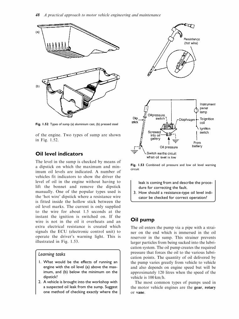
of the engine. Two types of sump are shownin Fig. 1.52.
Oil level indicators
The level in the sump is checked by means ofa dipstick on which the maximum and min-imum oil levels are indicated. A number ofvehicles fit indicators to show the driver thelevel of oil in the engine without having tolift the bonnet and remove the dipstickmanually. One of the popular types used isthe ‘hot wire’ dipstick where a resistance wireis fitted inside the hollow stick between theoil level marks. The current is only suppliedto the wire for about 1.5 seconds at theinstant the ignition is switched on. If thewire is not in the oil it overheats and anextra electrical resistance is created whichsignals the ECU (electronic control unit) tooperate the driver’s warning light. This isillustrated in Fig. 1.53.
Learning tasks
1. What would be the effects of running an
engine with the oil level (a) above the max-
imum, and (b) below the minimum on the
dipstick?
2. A vehicle is brought into the workshop with
a suspected oil leak from the sump. Suggest
one method of checking exactly where the
leak is coming from and describe the proce-
dure for correcting the fault.
3. How should a resistance-type oil level indi-
cator be checked for correct operation?
Oil pump
The oil enters the pump via a pipe with a strai-ner on the end which is immersed in the oilreservoir in the sump. This strainer preventslarger particles from being sucked into the lubri-cation system. The oil pump creates the requiredpressure that forces the oil to the various lubri-cation points. The quantity of oil delivered bythe pump varies greatly from vehicle to vehicleand also depends on engine speed but will beapproximately 120 litres when the speed of thevehicle is 100 km/h.
The most common types of pumps used inthe motor vehicle engines are the gear, rotaryor vane.
Fig. 1.52 Types of sump (a) aluminium cast, (b) pressed steel
Fig. 1.53 Combined oil pressure and low oil level warning
circuit
48 A practical approach to motor vehicle engineering and maintenance
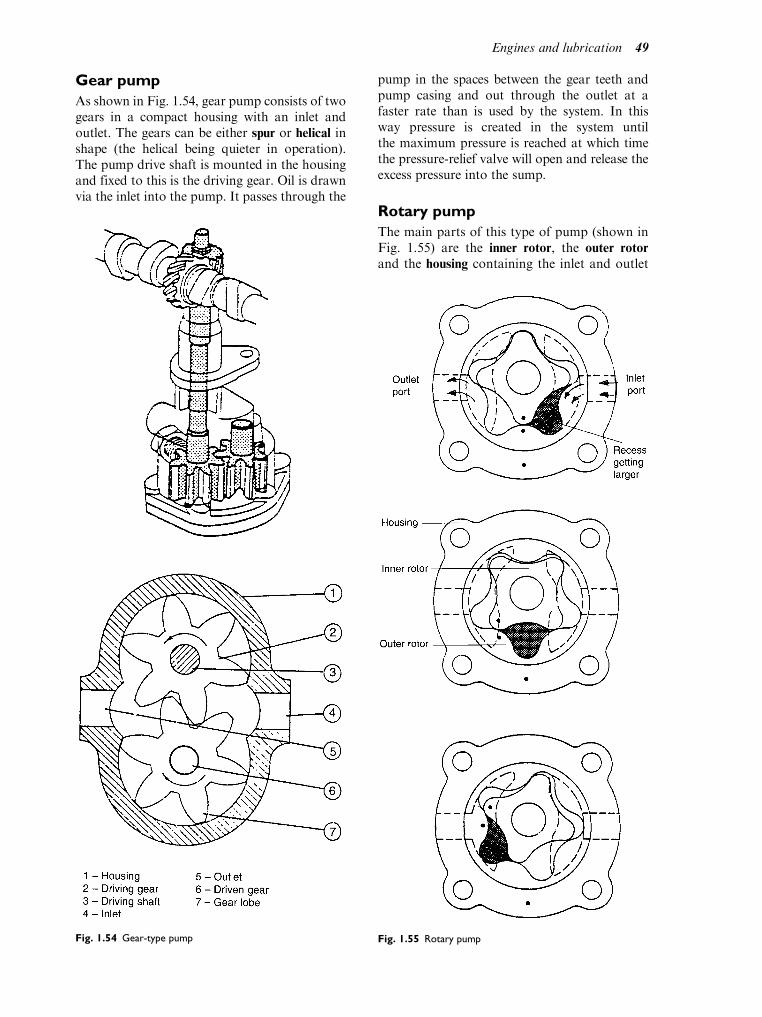
Gear pump
As shown in Fig. 1.54, gear pump consists of twogears in a compact housing with an inlet andoutlet. The gears can be either spur or helical inshape (the helical being quieter in operation).The pump drive shaft is mounted in the housingand fixed to this is the driving gear. Oil is drawnvia the inlet into the pump. It passes through the
pump in the spaces between the gear teeth andpump casing and out through the outlet at afaster rate than is used by the system. In thisway pressure is created in the system untilthe maximum pressure is reached at which timethe pressure-relief valve will open and release theexcess pressure into the sump.
Rotary pump
The main parts of this type of pump (shown inFig. 1.55) are the inner rotor, the outer rotor
and the housing containing the inlet and outlet
Fig. 1.54 Gear-type pump Fig. 1.55 Rotary pump
Engines and lubrication 49

ports. The inner rotor, which has four lobes, isfixed to the end of a shaft; the shaft is mountedoff-centre in the outer rotor which has fiverecesses corresponding to the lobes. When theinner rotor turns, its lobes slide over the corres-ponding recesses in the outer rotor turning it inthe pump housing. At the inlet side the recess issmall; as the rotor turns the recess increases insize drawing oil up from the sump into thepump. When the recess is at its largest the inletport finishes, further movement of the rotorreveals the outlet port and the recess begins todecrease in size forcing the oil under pressurethrough the outlet port.
Vane-type pump
This pump, shown in Fig. 1.56, takes the form ofa driven rotor that is eccentrically mounted(mounted offset) inside a circular housing. Therotor is slotted and the eccentric vanes are free toslide within the slots, a pair of thrust rings ensur-ing that the vanes maintain a close clearance withthe housing. When in operation the vanes arepressurized outwards by the centrifugal actionof the rotor rotating at high speed. As the pumprotates the volume between the vanes at the inletincreases, thus drawing oil from the sump intothe pump; this volume decreases as the oilreaches the outlet, pressurizing the oil and deliv-ering it to the oil gallery. This type has the advan-tage of giving a continuous oil flow rather thanthe pulsating flow that is rather characteristic ofthe gear-type pump.
Pressure-relief valve
As engine speed increases the oil pump producesa higher pressure than is required by the enginelubrication system. A pressure-relief valve (see Fig.1.57) is therefore fitted in the system to take away
the excess pressure and maintain it at a levelappropriate for the bearings and seals used. It willbe seen then that the relief valve performs twoimportant functions: first, it acts as a pressureregulator; and second, it acts as a safety devicein the lubrication system. The main types in useare the ball valve, the plate and the plunger orpoppet valve. Each is held in the closed positionby a spring. As the oil pressure in the oil galleryrises above the setting for the relief valve, the valveopens against spring pressure allowing the oil tobypass the system and return back to the sump viathe return outlet. The force on the spring deter-mines the oil pressure in the lubrication system.
Learning tasks
1. When next in the workshop, dismantle a
vane-, rotor- and gear-type oil pump. Using
the manufacturers’ data measure and record
the tolerances for each type and give your
recommendations on serviceability.
2. Remove the oil pressure switch from the oil
gallery of an engine and attach the appropri-
ate adapter to measure the oil pressure.
Record the results at the relevant speeds.
Identify any major differences between the
recorded results and the manufacturer’s
data and give your recommendations.
3. Give two reasons for low oil pressure
together with recommendations for cor-
recting the fault.
Oil filter
When the oil passes through the engine itbecomes contaminated with carbon (theFig. 1.56 Vane pump
Fig. 1.57 Oil pressure-relief valve
50 A practical approach to motor vehicle engineering and maintenance

byproduct of the combustion process), dust(drawn in from the atmosphere), small metalparticles (from components rubbing together),water and sludge (a combination of all theseimpurities mixed together). All these will causeengine wear if they remain in the oil, so theengine must be equipped with a filtering systemthat will remove them and keep the oil as cleanas possible. Most modern engines are equippedwith a filtering system where all the oil is filteredbefore it reaches the bearings. This arrangementis called the full-flow system. There is anothersystem also in use where only a portion of the oilpasses through the filter, called the bypass filtersystem. The two systems are shown in Fig. 1.58.
The importance of filtering the oil is shown bythe results of an investigation into the wear on thecylinder and piston, using the two filtering sys-tems. It was found that maximum wear (100%)occurs in engines working without an oil filter.When a bypass filter is used, wear is reducedto about 43% on the cylinder and 73% on thepiston, whichmeans that the life of the piston andcylinder are almost doubled. Minimum wearoccurs when a full-flow filter is used, wear isagain reduced by a further 15% on the cylinderand 22% on the piston. This means that the life ofthe piston and cylinder is four to five times longerthan in an engine working without a filter. Agood oil filter must be capable of stopping theflow of very small particles without restricting theflow of oil through the filter. To meet thisrequirement different materials are used as thefiltering medium. Resin-impregnated paper iswidely used, the paper being folded in order tomake a large surface area available for the oil to
flow through; particles are left on the paper andclean oil is passed to the lubrication system. Inthis way when the filter is changed the impuritiesare removed at the same time. In other types ofoil filters different kinds of fibrous materials areused. The filtering material is enclosed in perfo-rated cylinders, one outer and one inner to form afilter element (Fig. 1.59).
The oil enters through the perforations in thecylinder, passes through the filtering elementand leaves through the central tube outlet.Many modern filters are now the cartridge-typewhich is removed complete. The advantages ofthis disposable type are that it cleans the oil veryefficiently, it is relatively easy to change and it isless messy to remove. The filter element can alsobe located in a removable metal container. Withthe replaceable-element-type it is only the ele-ment itself that is changed, the container isthoroughly cleaned and the ‘O’ ring replaced.
Full-flow filter
Oil filter operation is shown in Fig. 1.60. Themost widely used filtering system is the full-flowfilter. The construction of the filter is very effi-cient because all the oil is passed through thefilter before it flows to the bearings. After acertain length of time the element becomes dirtyand less efficient and must therefore be changed.If the element is not changed regularly the impu-rities will accumulate and the element willbecome clogged, restricting or preventing theoil from passing through the filter. For thisreason a relief valve is fitted into the filter whichopens and allows the oil to bypass the clogged
Fig. 1.58 Lubrication systems (a) full flow system, (b) by-pass system
Engines and lubrication 51

filter element and flow directly to the bearingsunrestricted. If the condition is allowed to con-tinue, unfiltered oil will carry abrasive particlesto the bearings causing rapid wear.
Cartridge filter
In the cartridge filter the relief valve is in thefilter (shown in the open position in Fig. 1.61).Many of the filters now contain a valve
underneath the inlet hole which opens whenoil pressure forces oil into the filter. When theengine stops and the oil flow ceases, the valvecloses and the oil is kept within the filter. Thisprevents it from draining back into the sump. Italso has the advantage of enabling the engineto develop the oil pressure more quickly whenstarting from cold. Correct operation is shownin Fig. 1.62.
Fig. 1.59 The oil filter and pleated element
Fig. 1.60 Oil filter operation (a) oil being filtered, (b) oil filter blocked
52 A practical approach to motor vehicle engineering and maintenance

Disc filter
This type of full-flow filter (shown in Fig. 1.63) isused in large diesel engines. The oil is filtered bybeing forced through very narrow gaps (0.05mm)between thin steel discs which form an assemblywhich can be rotated. The narrow gap betweenthe discs prevents impurities in the oil frompassing through. The deposits accumulate onthe outside of the discs, which are kept clean by
scrapers which scrape off the deposits as the discassembly rotates. In most cases the assemblyis connected to the clutch pedal; each time thepedal is operated the disc assembly is rotated asmall amount. The filter must be drained asper manufacturers’ recommendations, this beingdone by removing the drain plug allowing dirtand some oil to be flushed out.
Centrifugal filter
Again mainly found on larger engines, this con-sists of a housing with a shaft and rotor inside.The oil is forced through the inlet ports by thepump and fills the rotor through the inlet holes inthe rotor shaft, passing down the pipes to the jets.Due to the force of the oil passing through thejets the rotor rotates at very high speed. Owing tothe centrifugal force, the impurities (which areheavier than the oil) accumulate on the walls ofthe rotor. The filter must be periodically cleanedby dismantling the filter and washing with asuitable cleaning fluid.
Learning tasks
1. Draw up a lubrication service schedule for a
12 000 mile major service.
2. Complete a lubrication service on a vehicle
using the above service schedule. Identify
any faults found, such as oil leaks, and com-
plete the report on the workshop job card.
Fig. 1.61 Cartridge oil filter with oil relief valve open
Fig. 1.62 Cartridge oil filter operating correctly
Fig. 1.63 Disc-type oil filter
Engines and lubrication 53

Dry-sump lubrication
This type of system (Fig. 1.64) is fitted to vehicleswhere the engine is mounted on its side, or wheregreater ground clearance is required. It is also usedfor motor cycle engines, cross-country vehicles andracing engines where under certain conditions thepick-up pipe could be exposed for a period of timeand therefore the oil supply to the engine lubrica-tion system could be interrupted. To overcome thisproblem a dry sump system is often fitted.
The oil is stored in a separate oil tank instead ofin the sump. The oil pump takes the oil from thetank and passes it to the lubrication system. Theoil then drops down to the crankcase where a
separate scavenge oil pump often running at ahigher speed than the pressure pump returns itback to the oil tank. This means that the sumpremains almost dry. The faster speed of the sca-venge pump is due to the fact that it must becapable of pumping amixture of air and oil (whichhas a larger volume than just oil) back to the tank.
Oil coolers (sometimes calledheat exchangers)
Two types of oil coolers are fitted where the heat isremoved from the oil: one is the oil-to-air wherethe heat is passed directly to the air; the other is theoil-to-water where the heat from the oil is passedto the water cooling system. Both types are shownin Fig. 1.65. On the water-cooled engines the oilcooler is normally located in front of, and some-times combined with, the radiator. The advantageof the water-type heat exchanger is that the oil andwater are operating at roughly the same tempera-ture and each is maintained at its most efficientworking temperature under most operating condi-tions. On air-cooled heat exchanger engines thecooler is usually located in the air stream of thecooling fan and is similar in construction to thecooling system radiator. An oil cooler bypassvalve is fitted in the system which allows the oilto heat up more rapidly from cold by initiallyrestricting its circulation to the engine only.
Total loss lubrication
There is one system commonly used that has sofar not been mentioned; that is the total losssystem. This is where the oil used to lubricatethe piston, main and big-end bearings, is burntduring the combustion stroke and therefore lostthrough the exhaust system to the atmosphere.
Fig. 1.64 Operation of dry-sump lubrication system
Fig. 1.65 Basic principles of oil coolers (a) oil-to-air, (b) oil-to-water
54 A practical approach to motor vehicle engineering and maintenance

One example of this is the two-stroke petrolengine used in the motor cycle.
Learning tasks
1. Remove the pump from a motor cycle engine
and identify the type of pump fitted and
method of operation. After reassembling
immerse the pump in clean engine oil and test
the pumping side for pressure and the sca-
venge side for suction. Record the results.
2. Give two methods used in the total loss lubri-
cation system of introducing oil into the engine.
3. How should engine oil be removed from the
workshop floor?
4. List the main safety precautions that should
be observed when working on the lubrica-
tion system.
Practical assignment –removing and refitting thecylinder heads
Objective
To visually check the condition of:
. the valves and valve seats
. the cylinder head for cracks and distortion
. the piston crowns for build-up of carbon
. the cylinder bores for scoring and excessive wear
Vehicle/engines used
This exercise should be carried out on both OHC
and push-rod operated engines.
Equipment required
. Specialist test equipment
. Small hand tools, e.g. spanners, sockets, etc.
. Valve spring compressors
. Torque spanner
. Relevant repair manual
. Drain trays
Task
Before removing the cylinder head the following
checks/tests should be carried out:
. compression test
. cylinder leakage test
. cylinder balance test
. pressure check the cooling system
. check the anti-freeze content of water
. check condition of engine oil
. check condition of water
Activity
1. Drain both engine oil and water.
2. Remove ancillary components, e.g.
(a) all electrical connections
(b) accelerator and choke cables
(c) water and air intake hoses/connections
(d) cam belt OHC (having set camshaft tim-
ing) inlet and exhaust manifolds
3. Remove camshaft (OHC) or rocker shaft and
push rods.
4. Remove cylinder head (ensure bolts/nuts are
released in the correct order).
5. Remove all the inlet and exhaust valves
(ensure these are kept in the correct order).
6. Thoroughly clean all the components.
7. Visually inspect valve seats for pitting on seats
and measure for wear on stems.
8. Visually check cylinder head for cracks and
distortion.
9. Visually check valve seats in cylinder head for
pitting and burning.
10. Reface valves and seats or replace as
necessary.
11. Regrind valves into cylinder head.
12. Reassemble valves into cylinder head using
new valve stem seals. Adjust clearances as
necessary OHC.
13. Refit cylinder head to engine using new gas-
kets and bolts where required.
14. Tighten cylinder head bolts to the correct
torque using recommended procedure.
15. Replace all ancillary equipment/components.
16. Fill with fresh oil and where appropriate
water/anti-freeze.
17. Check operation by starting and running
engine.
18. Check for water and oil leaks, check levels and
adjust settings as necessary.
Typical assessment sheet
This should be completed by the assessor during
the assignment. Student will also produce a report
to go with this assessment sheet.
Engines and lubrication 55

Self assessment questions
1. If a worn engine oil pump causes low oil
pressure:
(a) the oil pressure can be increased by increas-
ing the spring pressure of the oil pressure
relief valve
(b) increasing the oil pressure relief valve spring
pressure will make no difference to the oil
pressure
(c) the engine oil should be changed for one
with a higher viscosity index
(d) the by-pass valve in oil filter should be
adjusted.
2. When checking valve clearances on a 4 cylinder
in-line engine:
(a) the clearance on number 1 valve may be
checked when number 8 valve is fully open
(b) the valves on number 4 cylinder should be
‘rocking’ when the valve clearances on num-
ber 1 cylinder are being checked
(c) the engine must be hot
(d) the clearance should be checked by means
of an engineer’s rule.
3. Piston rings are gapped:
(a) so that they can be fitted to the piston
(b) to allow a path for oil to reach the combus-
tion chamber
(c) to allow for thermal expansion
(d) to prevent ring flutter.
4. Big end bearings are lubricated:
(a) by oil mist that rises from agitation of oil in
the sump
(b) by splash lubrication piston
(c) by oil that is fed to them through oilways in
the crankshaft
(d) by oil that is fed to them through holes
drilled in the connecting rod.
5. The diameter at the top land of an aluminium
alloy piston is:
(a) smaller than the diameter at the piston skirt
to allow for expansion
(b) smaller than the diameter at the piston skirt
to prevent the piston hitting the wear ridge
(c) larger than the diameter on the skirt to
provide a good gas seal
(d) the same size as the remainder of the piston.
6. When the piston of number 1 cylinder of a 4
cylinder, 4 stroke, in-line engine is at TDC at
the beginning of the firing stroke:
(a) number 4 piston is at the beginning of
exhaust stroke
(b) number 4 piston is at the beginning of the
induction stroke
(c) the valves on number 1 cylinder are open
(d) combustion will be taking place in cylinder
number 3.
7. When replacing a cylinder head:
(a) the bolts should be tightened by starting at
the front of the cylinder head and working
towards the back
(b) the bolts should be tightened by starting
at the middle of the cylinder head and
working outwards in accordance with
the order shown in the instruction man-
ual
(c) the bolts should be torqued down to the
final setting in a single operation
(d) the bolts should be ‘run down’ finger tight
and then fully tightened after the engine
has been restarted and warmed up to
normal operating temperature.
8. End thrust on the crankshaft shown in Fig. 1.32
is taken by the component marked:
(a) 13
(b) 16
(c) 3
(d) 22.
9. A full flow oil filter is fitted with a by-pass
valve:
(a) to prevent excessive oil consumption
(b) to allow oil to reach the oil galleries in the
event of filter blockage
(c) as a substitute for an oil pressure relief
valve
(d) to allow excess oil from the gallery to leak
back through the oil pump.
10. In a certain engine , the inlet valve opens 5
degrees before TDC and closes 40 degrees
after BDC. The inlet valve period is:
(a) 215 degrees
(b) 45 degrees
(c) 225 degrees
(d) 135 degrees.
56 A practical approach to motor vehicle engineering and maintenance

Name Date
Practical assignment Tutor/assessor
General comments
from
to
Comments on specifictasks
Testequipment
Removingancillaries
Removing/refittingvalves
Refittingcylinderhead
Checkingand runningengine
Tas
ks
Cho
oses
cor
rect
tool
s an
d op
erat
es e
quip
men
t pro
perly
Gen
eral
cle
anlin
ess
of w
ork/
task
Use
s sa
fe w
orki
ng p
ract
ices
Iden
tifie
s co
mpo
nent
s co
rrec
tly
Loca
tes
and
uses
tech
nica
l inf
orm
atio
n
Com
plet
es ta
sk s
ucce
ssfu
lly
Iden
tifie
s an
y pr
oble
ms
Com
pile
s re
port
on
com
plet
ed ta
sk
Engines and lubrication 57
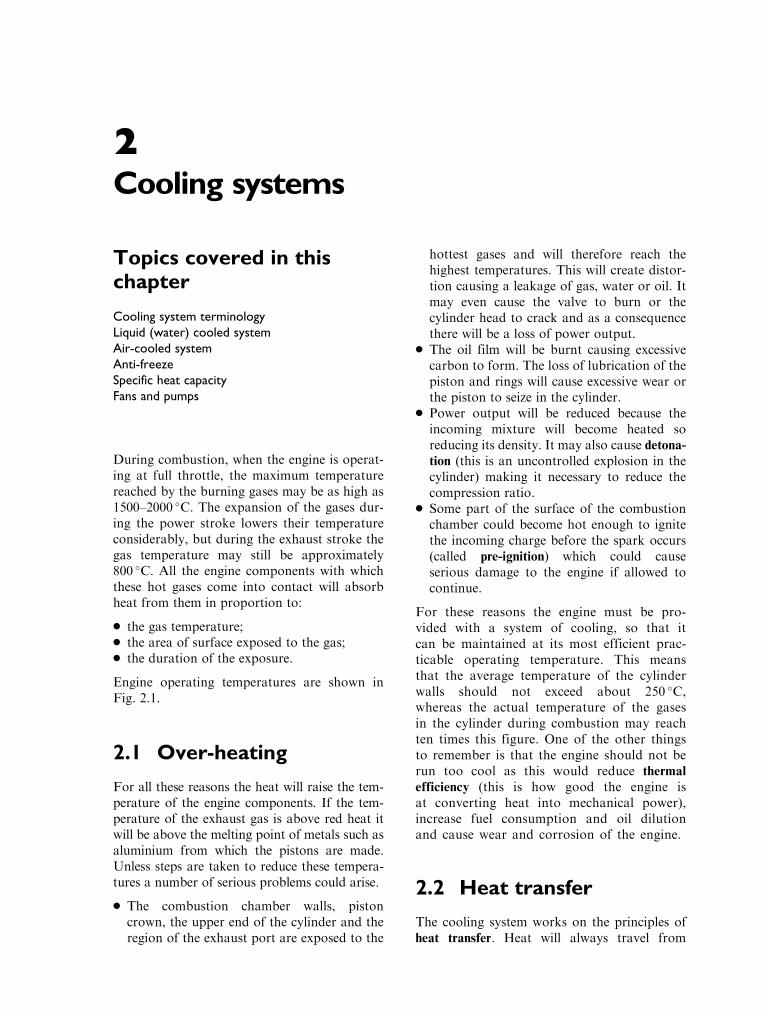
2Cooling systems
Topics covered in thischapter
Cooling system terminology
Liquid (water) cooled system
Air-cooled system
Anti-freeze
Specific heat capacity
Fans and pumps
During combustion, when the engine is operat-ing at full throttle, the maximum temperaturereached by the burning gases may be as high as1500–2000 C. The expansion of the gases dur-ing the power stroke lowers their temperatureconsiderably, but during the exhaust stroke thegas temperature may still be approximately800 C. All the engine components with whichthese hot gases come into contact will absorbheat from them in proportion to:
. the gas temperature;
. the area of surface exposed to the gas;
. the duration of the exposure.
Engine operating temperatures are shown inFig. 2.1.
2.1 Over-heating
For all these reasons the heat will raise the tem-perature of the engine components. If the tem-perature of the exhaust gas is above red heat itwill be above the melting point of metals such asaluminium from which the pistons are made.Unless steps are taken to reduce these tempera-tures a number of serious problems could arise.
. The combustion chamber walls, pistoncrown, the upper end of the cylinder and theregion of the exhaust port are exposed to the
hottest gases and will therefore reach thehighest temperatures. This will create distor-tion causing a leakage of gas, water or oil. Itmay even cause the valve to burn or thecylinder head to crack and as a consequencethere will be a loss of power output.
. The oil film will be burnt causing excessivecarbon to form. The loss of lubrication of thepiston and rings will cause excessive wear orthe piston to seize in the cylinder.
. Power output will be reduced because theincoming mixture will become heated soreducing its density. It may also cause detona-tion (this is an uncontrolled explosion in thecylinder) making it necessary to reduce thecompression ratio.
. Some part of the surface of the combustionchamber could become hot enough to ignitethe incoming charge before the spark occurs(called pre-ignition) which could causeserious damage to the engine if allowed tocontinue.
For these reasons the engine must be pro-vided with a system of cooling, so that itcan be maintained at its most efficient prac-ticable operating temperature. This meansthat the average temperature of the cylinderwalls should not exceed about 250 C,whereas the actual temperature of the gasesin the cylinder during combustion may reachten times this figure. One of the other thingsto remember is that the engine should not berun too cool as this would reduce thermal
efficiency (this is how good the engine isat converting heat into mechanical power),increase fuel consumption and oil dilutionand cause wear and corrosion of the engine.
2.2 Heat transfer
The cooling system works on the principles ofheat transfer. Heat will always travel from

hot to cold (e.g. from a hot object to a coldobject, this would be by conduction). This trans-fer occurs in three different ways:
. conduction
. convection
. radiation
Conduction is defined as the transfer of heatbetween two solid objects, e.g. valve stem to valveguide as shown in Fig. 2.2. Since both objects aresolid, heat is transferred from the hot valve stemto the cool valve guide by conduction and alsofrom the guide to the cylinder head.
Convection is the transfer of heat by the cir-culation of heated parts of a liquid or gas. Whenthe hot cylinder block transfers heat to the cool-ant it produces a change in its density andcauses the warmer less dense water to rise, thussetting up convection currents in the coolingsystem.
Radiation is defined as the transfer of heat byconverting it to radiant energy. Radiant heat is
emitted by all substances and may be reflectedor absorbed by others. This ability will dependupon the colour and nature of the surface of theobjects, for example, black rough ones are bestfor absorption of heat and light polished onesbest for reflection of heat.
The cooling system relies on all three of theseprinciples to remove excess heat from theengine.
Learning tasks
1. Take a look at three different types of radia-
tors and check the colour and texture of the
surface finish. Why are they finished like
this?
2. How is the heat taken away from the top of
the piston and spark plug? Which of the
three methods named above are used?
2.3 Over-cooling
As we have seen, various problems can occur ifthe engine temperature gets too high but if thetemperature becomes too low then another setof problems can occur.
. Fewer miles per gallon as the combustionprocess will be less efficient.
. There will be an increase in the build-up ofcarbon (as the fuel enters the cylinder itwill condense and cause excessive build-upof carbon on the inlet valves).
Fig. 2.1 Engine operating temperature ranges
Fig. 2.2 Heat is transferred by conduction from the valve stem
to the valve guide. Both objects are solid
Cooling systems 59

. There will be an increase in the varnish andsludges formed within the lubrication system.Cooler engines make it easier for these to form.
. A loss of power, because if the combustionprocess is less efficient the power output willbe reduced.
. The fuel not being burned completely whichwill cause fuel to dilute the oil and causeexcessive engine wear.
The purposes of the cooling system can besummarized as follows:
. to maintain the highest and most efficientoperating temperature within the engine;
. to remove excess heat from the engine;
. to bring the engine up to operating tempera-ture as quickly as possible – in heavy dutydriving, an engine could theoretically produceenough heat to melt an average 100 kg engineblock in 20 minutes.
2.4 Types of coolingsystems
There are two main types of cooling systems incommon use, air and water. Both dissipate(radiate) heat removed from the cylinder intothe surrounding air. Air cooling is describedbelow and water cooling in Section 2.6.
Air cooling
In this system heat is radiated from the cylinderand head directly into the surrounding air. Therate at which heat is radiated from an object isdependent on:
1. the difference in temperature between theobject and the surrounding air;
2. the surface area from which the heat isradiated (since (1) must be limited, the sur-face area of the cylinder and head exposed tothe air must be increased, by forming fins ontheir external surfaces) (Fig. 2.3);
3. the nature of the surface.
It is also necessary to remove the heated airfrom around the cylinder and deliver a constantsupply of cool air around and between the fins.This means that the cylinders must be suffi-ciently widely spaced to permit a suitable depthof finning all around them, and the engine mustbe placed where the movement of the vehiclecan provide the necessary supply of cool air.
A large fan is often used and the engine is sur-rounded by large cowls to direct air to where it isrequired, e.g. around the cylinder head andvalve area.
The choice of air or liquid cooling has alwaysbeen controversial. Air is cheaper, lighter andmore readily obtainable than water – though toremove a given quantity of heat demands fourtimes the weight and 4000 times the volume ofair than it does water. It also gives less controlof the engine temperature and air-cooledengines tend to be noisier. But air can be col-lected and rejected, whereas water must be car-ried on the car and the jacketing, hoses, pumpand radiator of a water-cooled engine will prob-ably weigh more than the substantial fins of anair-cooled engine.
However, the fins force the cylinders of anair-cooled engine to be more widely separatedthan those of a water-cooled engine, so thecrankshaft and crankcase must be longer andtherefore heavier. For an engine of many cylin-ders, this is one of the greatest objections to aircooling.
2.5 Engine air-coolingsystem
Circulation of cooling air
With air cooling the engine structure is directlycooled by forcing air over its high-temperaturesurfaces. These are finned to present a greatercooling surface area to the air, which in
Fig. 2.3 Air-cooled finned cylinder wall method of heat
transfer
60 A practical approach to motor vehicle engineering and maintenance

nonmotor-cycle applications is forced to circu-late over them by means of a powerful fan.
The engine structure is almost entirely enclosedby sheet metal ducting (called a cowl), whichincorporates a system of partitions (called baf-
fles); these ensure that the air flow is properlydirected over the cylinders and cylinder heads.To obtain uniform temperatures the air is forcedto circulate around the entire circumference ofeach cylinder and its cylinder head. The direction
of air flow will be along the cooling fins, thegreatest number of which are found towards thetop of the cylinder (around the exhaust valve) asthis is the hottest part of the engine.
The complete system forms what is known asthe plenum chamber in which the internal airpressure is higher than that of the atmosphere.The heated air is discharged from the plenumchamber to the atmosphere, or redirected toheat the car interior. Figure 2.4 shows a
Fig. 2.4 Cut-away view of modern air-cooled diesel engine
Cooling systems 61

modern, air-cooled diesel engine. In order toprovide the necessary air flow around the cylin-ders of an enclosed engine, a powerful fan isessential.
Types of air-cooling fans
Axial flow
This is a simple curved blade type in which thedirection of air flow is parallel to the axis of thefan spindle (Fig. 2.5).
Radial flow
Often called a centrifugal this type (Fig. 2.6) ismore commonly used because it is more effec-tive and a fan of smaller diameter can be usedfor a given air flow. This type of fan has anumber of curved radial vanes mountedbetween two discs, one or both having a largecentral hole. When the fan is rotated, airbetween the vanes rotates with it and is thrownoutwards by centrifugal force.
Figure 2.7 shows a simple air-cooled systemfor a four-cylinder in-line engine. A centrifugalfan, driven at approximately twice crankshaft
speed, is mounted at the front of the engineand takes in air through a central opening (5)in the fan casing. This air is delivered into thecowl (3) where it is directed over the fins of thecylinders (1). Baffles (2) ensure that the airpasses between the fins where it picks up heat,thus cooling the cylinders.
The in-line engine is the most difficult to coolby air. Vee-type or horizontally opposed enginesare easier to cool as the cylinders are spacedfurther apart to leave room for the crankshaftbearings and this allows more room between thecylinders for a good air flow whilst at the sametime keeping the total engine length fairly short.
Learning tasks
1. What safety precautions should be observed
when working on air-cooled systems?
2. What are the main difficulties with working
on air-cooled engines?
3. Remove the cowling from an air-cooled
engine, clean any excessive dirt, etc. from
between the fins of the cylinders. Reassem-
ble the cowling and test engine for correct
operating temperature.
2.6 Liquid cooling
In this arrangement the outer surfaces of thecylinder and head are enclosed in a jacket, leav-ing a space between the cylinder and the jacketthrough which a suitable liquid is circulated.
Fig. 2.5 Axial air flow fan
Fig. 2.6 Radial air flow fan
Fig. 2.7 Simple in-line air-cooled engine using a radial type fan
62 A practical approach to motor vehicle engineering and maintenance

The liquid generally used is water, which is inmany ways the most suitable for this purpose,even though it has a number of drawbacks.Whilst passing through the jacket the waterabsorbs heat from the cylinder and head, andit is cooled by being passed through a radiatorbefore being returned to the jacket.
Thermo-syphon system
When heated, the water becomes less dense andtherefore lighter than cold water. Thermosy-phon is the action of the water being heated,rising and setting up convection currents in thewater. The thermo-syphon system is no longerused in the modern motor vehicle as it has anumber of disadvantages.
. To ensure sufficient circulation the radiatormust be arranged higher than the engine toensure that the heated coolant will rise intothe top of the radiator header tank and thecooled water in the radiator will flow into thebottom of the engine.
. Water circulation will be slow, so a relativelylarge amount of water must be carried.
. Large water passages must be used to allow anunrestricted flow of water around the system.
This system is usually now confined to smallstationary engines such as those used topower narrow boats, small generators, waterpumps, etc.
Pump-assisted circulation
Most modern engines use a pump to providea positive circulation of the coolant. This isshown in Fig. 2.8 and gives the followingadvantages:
1. a smaller radiator can be used than in thethermo-syphon system;
2. less coolant is carried as the water is circu-lated faster and therefore the heat is removedmore quickly;
3. smaller passages and hoses are used becauseof (2) above;
4. the radiator does not need to be abovethe level of the engine, giving a lower bon-net line; this also has the advantage ofless wind resistance giving a better fuelconsumption;
5. because the water flow is given positive direc-tion the engine will operate at a more eventemperature.
Fig. 2.8 Coolant is pumped from the water pump, through the cylinder block and heads, through the thermostat into the radiator, and
back to the water pump
Cooling systems 63

2.7 Comparison of air- andwater-cooled systems
Advantages of air cooling
. An air-cooled engine is generally lighter thanan equivalent water-cooled engine.
. It warms up to its normal running tempera-ture very quickly.
. The engine can operate at a higher tempera-ture than a water-cooled engine.
. The system is free from coolant leakage prob-lems and requires no maintenance.
. There is no risk of damage due to freezing ofthe coolant in cold weather.
Disadvantages of air cooling
. A fan and suitable cowls are necessary to pro-vide and direct the air flow.The fan canbe noisyand absorbs a large amount of engine power.The cowl makes it difficult to get at variousparts of the engine when servicing is required.
. The engine is more liable to over-heating underdifficult conditions than awater-cooled engine.
. Mechanical engine noises tend to be ampli-fied by the fins.
. The cylinders usually have to be made sepa-rately to ensure proper formation of the fins.This makes the engine more costly to manu-facture.
. Cylinders must be spaced well apart to allowsufficient depth of fins.
. It is more difficult to arrange a satisfactorycar-heating system.
Advantages of water cooling
. The temperatures throughout the engine aremore uniform, thus keeping distortion to aminimum.
. Cylinders can be placed closer togethermakingthe engine more compact.
. Although a fan is usually fitted to force airthrough the radiator, it is much smaller thanthe type required for an air-cooled engine. Ittherefore absorbs less power and is quieter inoperation.
. There is no cowl to obstruct access to theengine.
. The water jacket absorbs some of the mechan-ical noise making the running engine quieter.
. The engine is better able to operate underdifficult conditions without over-heating.
Disadvantages of water cooling
. Weight – not only of the radiator and con-nections but also of the water; the wholeengine installation is likely to be heavier thanan equivalent air-cooled engine.
. Because the water has to be heated, it takeslonger to warm up after starting from cold.
. If water is used, the maximum temperatureis limited to about 85–90 C to avoid therisk of boiling away the water. However,modern cooling systems are pressurizedand this permits higher temperatures andbetter efficiency.
. If the engine is left standing in very coldweather, precautions must be taken to pre-vent the water freezing in the cylinder jacketsand cracking them.
. There is a constant risk of a coolant leakagedeveloping.
. A certain amount of maintenance is necessary,for example, checking water level, anti-frostprecautions, cleaning out deposits, etc.
Learning task
Using the above information write a short
paragraph to explain the main components
and their purpose in the water cooling
system.
2.8 Radiator and heatermatrix
The purpose of the radiator is to provide a cool-ing area for the water and to expose it to the airstream. A reservoir for the water is included inthe construction of the radiator. This is knownas the header tank and is made of thin steel orbrass sheet and is connected to the bottom tankby brass or copper tubes; these are surroundedby ‘fins’. This assembly is known as the matrix,core, block or stack. The more modern radiatoruses plastic for the tanks and aluminium for thematrix. Shown in Fig. 2.9(a) is a conventionaltype of radiator. Figure 2.9(b) shows a typicaltype of cross-flow radiator which has an integraloil cooler fitted.
The function of the radiator as we have saidis to transfer heat from the coolant to the airstream. It is designed with a very large surfacearea combined with a relatively small frontalarea, and it forms a container for some of the
64 A practical approach to motor vehicle engineering and maintenance

coolant in the system. The radiators usuallyhave mounting feet or brackets, a filler cap, anoverflow pipe and sometimes a drain tap isfitted to the lower tank.
A large number of different types of radiatormatrix are in common use depending on appli-cation size of engine, etc. Details of the maintypes in common use are given below.
Film core
The tubes are the full width of the core and arebent to form square spaces through which air canpass. They are sometimes crinkled to extend theirlength. The top and bottom tanks are secured toside frames with the core located between themand a fan cowl often completes the unit.
Fig. 2.9 (a) Conventional vertical flow radiator, (b) the parts of a standard cross-flow radiator
Cooling systems 65

Tube and fin
This consists of copper or brass tubes of round,oval or rectangular cross-section. The tubespass through a series of thin copper fins withthe top and bottom tanks attached to the upperand lower fins, respectively. The fins secure thetubes and increase the surface area from whichthe heat can be dissipated. The tubes are placededge on to the air flow for minimum air resis-tance and they are now produced from striplock-seaming.
Tube and corrugated film
Sometimes used as an alternative to the tubeand fin, the corrugated separator filming ismade from copper and laid between the tubesto provide an airway. Each face of the filming islouvred to increase air turbulence as the airpasses through. This improves the cooling effi-ciency of this design. A commonly used form ofradiator matrix (core) construction is shown inFig. 2.10.
Separate tubes
Radiators with separate coolant tubes are occa-sionally used. They provide a stronger core thanthe other types but they are more costly to build,heavy, time-consuming to repair and because ofthis are mainly confined to commercial vehicleapplications. The tanks and side frames areusually bolted together and locate the thickwalled tubes of rectangular or circular cross-section. The tubes are made watertight in theupper and lower tanks with rubber and metal
seals, and they have bonded copper fins or aspiral copper wire wound over their completelength to increase their ability to dissipate theheat. Tube removal and refitting may be doneby two methods depending on their construc-tion. One is to remove top and bottom tanksfrom their side frames, the other is to spring thetubes in and out, which is only possible becauseof their flexibility.
Separate expansion or header tanks
Separate expansion or header tanks are nowcommonly used. These allow the radiator to befitted lower than the engine and, on a commer-cial vehicle, to be fitted in a more accessibleposition for checking and refilling the coolant.The tank is also used to reduce the risk of aera-tion (this is air bubbles forming in the water) ofthe coolant when the engine is running. Theearly types of radiators were all of the conven-tional type, for example, the coolant flows fromthe top of the radiator to the bottom (verti-cally). Many vehicles now use a cross-flow typein which the coolant flows horizontally throughthe core from the top of one side tank across tothe bottom of the other side tank as shown inFig. 2.11.
Learning tasks
1. What are the advantages of a cross-flow
radiator?
2. How should the radiator be tested for leaks
when removed from the vehicle?
3. Why is the radiator painted matt black?
Fig. 2.10 Inside the radiator there are small tubes through which the coolant flows, helping to remove the heat into the air
66 A practical approach to motor vehicle engineering and maintenance

2.9 Water pump
The purpose of the water pump is to provide apositive means of circulating the water (it gives adirection to its flow, it does not pressurize thesystem).
The body of the pump is usually made of castiron or aluminium. In most cases it is bolted tothe front of the engine block and draws coolwater from the bottom of the radiator via thebottom hose. This cooler water is directed intothe water jacket and over the hottest part of theengine such as the exhaust valve seats. Twotypes of pump are used, axial flow and radial
flow.
Axial flow
With the axial flow, when the pump is full ofwater, the rotating impeller carries with it thewater contained in the spaces between theimpeller blades and the casing. This water issubjected to centrifugal force which causes it toflow outwards from inlet to outlet. A carbonring bonded to a rubber sleeve is fitted into thehousing and pressed into light contact with amachined face on the impeller by a lightspring.
This provides a water-tight seal along theshaft. The pump is driven by a belt from
the crankshaft via a pulley which is a press fiton the end of the pump spindle. The fan is thenbolted to the pulley which draws air through theradiator.
Radial flow
The radial flow centrifugal pump operates witha slightly higher flow and therefore the circula-tion is slightly faster. This type is fitted to com-mercial vehicles. The construction of such awater pump is shown in Fig. 2.12.
Learning tasks
1. What are the symptoms of the water
pump not working? What could be the
cause of this fault and how should it be
repaired?
2. How should the drive belt to the pump be
checked? Remove the belt, check for signs
of wear or cracking. Replace and correctly
tension the belt.
3. Remove one type of water pump from an
engine, check for premature bearing failure,
signs of water leaks and general serviceabil-
ity. Replace the pump, refill with coolant and
pressure test the system.
Fig. 2.11 Cooling system water flow
Cooling systems 67

2.10 Thermostat
This is a temperature sensitive valve that con-trols the water flow to the radiator. There aretwo main reasons for its use:
. to enable the engine to warm up quickly fromcold;
. to control the rate of flow and so maintain aconstant temperature in the engine.
Two types are in common use, the bellows typeand the wax type.
Wax type
This is used in the pressurized system as it isnot sensitive to pressure like the bellows type.A special wax is used, contained in a strongsteel cylinder. The reaction pin is surroundedby a rubber sleeve and is positioned inside thecylinder.
As the temperature increases the wax beginsto melt, changing from a solid to a liquid, andat the same time it expands. This forces therubber against the fixed reaction pin, openingthe valve against spring pressure thus allowingthe water to circulate through the radiator.There is a small hole in the valve disc toassist in bleeding the system as filling takesplace. The ‘jiggle pin’ closes the hole duringengine warm-up. This thermostat is shown inFig. 2.13.
Bellows type
As shown in Fig. 2.14. Bellows type consists ofa flexible metal bellows which is partly filled witha liquid which has a boiling point that is lowerthan that of water (e.g. alcohol, ether or acetone).Air is removed from the bellows, leaving onlythe liquid and its vapour. The pressure in thebellows is then only due to the vapour pressureof the liquid. This varies with temperature, andis equal to atmospheric pressure at the boilingtemperature of the liquid, less at lower tempera-tures and more at higher temperatures. As thetemperature of the water increases, the liquid inthe bellows begins to turn to a vapour andincrease in pressure; this expands the bellowsand opens the valve allowing water to pass tothe radiator.
Fig. 2.12 Radial flow centrifugal pump
Fig. 2.13 Wax pellet-type thermostat
Fig. 2.14 Bellows-type thermostat
68 A practical approach to motor vehicle engineering and maintenance

Note: This type is not suitable for pressurized
systems as the valves are pressure-sensitive.
The wax element type does not have this dis-
advantage.
Testing thermostats
The thermostat cannot be repaired and so mustbe replaced if found to be faulty. It can be testedby placing the thermostat in a beaker of waterand gradually heating it. A thermometer is usedto check the temperature of the water (Fig. 2.15).The thermostat should begin to open when thetemperature marked on the valve is reached. Anincrease of approximately 10–20 C will elapsebefore the valve is fully open.
Learning tasks
1. Write a schedule for removing, testing and
replacing a thermostat that is suspected of
being faulty.
2. What is the symptom, fault, cause and
remedial action that should be taken when
the driver complains of the heater blowing
hot and cold?
3. Remove, test and replace a thermostat
according to your work schedule drawn up
at (l) above. State the type of unit fitted, the
temperature at which it opened/closed and
check with the manufacturer’s data.
2.11 Pressurized coolingsystems
Pressurised cooling systems are used becausethey allow the engine to operate at a higher
temperature. Figure 2.16 shows the layoutand main components of a modern pressurizedsystem.
Pressure cap
The cap contains two valves; one is the pressure
valve the other is the vacuum valve. As the tem-perature of the water increases it expands and ina sealed system this expansion increases the pres-sure until it reaches the relief pressure of the cap.As the system cools down it contracts and opensthe vacuum valve drawing in air. If no vacuumvalve was fitted the depression in the system,caused by the contracting effect of the water asit cools, could cause the rubber hoses in thesystem to collapse. Most pressure caps operateat 28–100kN/m. The pressure is usually stampedon the cap indicating the maximum relief pres-sure for the system to which it is fitted. Figure2.17(c) shows a pressure cap in the open position.
Safety note
Never remove the cap when the coolant tem-
perature is above 100 C as this will allow the
water to boil violently: the resulting jet of
steam and water from the open filler can cause
very serious scalds. The system should be
allowed to cool down and the cap removed
slowly. It is designed so that the spring disc
remains seated on the top of the filler neck
until after the seal has lifted. This allows the
pressure to escape through the vent pipe
before it can escape from the main opening.
The temperature at which a liquid boils risesas the pressure acting on it rises. This is shownin Fig. 2.18. The cooling system’s pressure ismaintained by the use of a pressure cap fittedto the top of the radiator or expansion bottle.This closes the system off from the atmospherecreating a sealed system.
The advantages of using a pressurized systemare:
. elimination of coolant loss by surging of thecoolant during heavy braking;
. prevention of boiling during long hill climbs,particularly in regions much above sea level;
. raising of the working temperature improvingengine efficiency;
. allowing the use of a smaller radiator to dis-sipate the same amount of heat as a largerone operating at a lower temperature.
Fig. 2.15 Thermostat suspended in water container
Cooling systems 69

Semi-sealed system
The advantage of the modern sealed coolingsystem is that it reduces the need for frequent
inspection of the coolant level and the risk ofweakening the anti-freeze solution by toppingup. Although the pressure cap provided asemi-sealed system the fully sealed system hasin effect a means of recovering the coolant thatis lost when the engine is at its operating tem-perature and the pressure cap is lifted. It con-sists of an expansion tank that is mountedindependently from the radiator and vented tothe atmosphere. A flexible hose connects theoverflow pipe of the radiator to a dip tube in
Fig. 2.16 ‘Degas’ system with coolant at normal operating pressure and temperature
Fig. 2.17 Open-type pressure cap used in the semi-sealed
system. (a) Pressure-relief valve open, (b) vacuum-relief valve
open and (c) cap-removal precaution action
Fig. 2.18 Variation of boiling point of water with pressure
70 A practical approach to motor vehicle engineering and maintenance

the overflow tank. As the coolant heats up thepressure valve in the cap opens and excess cool-ant passes to the expansion tank. When thesystem cools down the coolant is drawn backinto the radiator again through the vacuumvalve in the cap. This is shown in Fig. 2.19.
Fully sealed system
In the fully sealed system, the pressure cap isfitted to the expansion tank and a simple capis used on the radiator. The operation of thesystem is much the same as in the semi-sealedsystem. The reservoir is vented to the atmo-sphere and should be approximately two-thirdsfull. If the coolant falls below the minimum levelindicated on the tank air may be drawn into theradiator.
Learning tasks
1. What is the correct method for testing the
pressure and vacuum valves in the cap? What
would be the effect of fitting a cap with: (a) a
stronger spring? (b) a weaker spring?
2. How would you test for water/oil contam-
ination and which component would you
suspect to be faulty?
2.12 Fans and theiroperation
Fans and temperature control
An important aspect of the cooling capabili-ties of the radiator is the volume of air, in unittime, which can be caused to flow through the
matrix. Hence, the purpose of the cooling fanis to maintain adequate air flow through thematrix, at low and engine idling speeds. Thespeed of the fan ranges from slightly less torather more than that of the engine. Excessivefan speeds are avoided because of noise andthe power required to drive it.
Electrically driven fans
With this type of fan arrangement an electricmotor is used together with a fan and atemperature-sensitive control unit. The advan-tages of this arrangement are:
. the fan only operates when the engine reachesits predetermined temperature;
. the engine will be more efficient as the fan isnot being driven all the time;
. the radiator and fan can now be fitted in anyconvenient position, ideal for transverselymounted engines;
. the fan assembly can be mounted in front ofor behind the radiator;
. engine temperature is more closely controlledas the temperature sensor will automaticallyswitch the fan on and off within very closelimits as required.
A typical layout is shown in Fig. 2.20.To improve the efficiency of the fan a cowl
is often fitted. Its function is to preventheated air from reversing its flow past thefan and recirculating through the matrixwhich could lead to engine overheating. Thefan can be formed from some of the followingmaterials:
. one piece steel pressing
. aluminium casting
. plastic moulding with a metal insert
An uneven number of irregularly spacedblades (Fig. 2.21) are often employed to mini-mize fan noise. In all applications thefan assembly must be accurately balancedand the blades correctly aligned to avoidvibration.
Flexible fan blades
Used to reduce frictional power loss from thefan, these are made from fibreglass, metal andmoulded plastic such as polypropylene. Theplastic fans are lighter, easier to balance, lookbetter, are more efficient aerodynamically, have
Fig. 2.19 Operating function of the overflow bottle.
(a) Water heating up, (b) water cooling down
Cooling systems 71

a reduced noise level, a reduction in vibrationand offer less risk of serious injury. They arealso cheaper to manufacture. For these reasonsthe plastic fan is the most common of this typefitted to light vehicles.
A number of vehicles have a cover sur-rounding the fan (called a shroud) fitted tomake sure the fan pulls air through the entireradiator. Figures 2.20 and 2.22 show arrange-ments commonly used. When no shroud isused the fan will only pull air through theradiator directly in front of the blades. Thereis very little air moving through the cornersof the matrix.
With flexible fan blades, as the speed of theengine increases the blades flatten and thereforemove less air, this give a reduction in the powerlost to friction. An example of a flexible fan witha shroud is that used in the Mini; the air isforced through the radiator, not drawn throughas in most vehicles.
Cooling fan with swept tips
The flexible tips of the fan tend to straightenout as speed increases and this has the effectof reducing the amount of air drawn throughthe fan.
Fig. 2.20 Layout for the Ford transverse engine
72 A practical approach to motor vehicle engineering and maintenance

Cooling fan surrounded by cowl orshroud attached to the radiator
The shroud is a close fit around the radiator andfan to prevent the air from just circulatingaround the fan and not passing through theradiator matrix and cooling the water.
Directly driven fans
Directly driven fans are not normally used inlight vehicles because they have the followingdisadvantages:
. rising noise level
. increase in power used
. tendency to over-cooling at higher speeds
Some engine manufacturers still use directlydriven fans mainly because of the type of enginefitted or because space is limited. The opposed
piston engine often has the fan blades bolteddirectly on the end of the crankshaft, usuallywith some means of limiting the maximumspeed of the fan. LGVs may also use the samemethod of driving the fan.
Fan drives
The drive for the fan is normally located on thewater pump shaft. Its purpose is to draw suffi-cient air through the matrix for cooling pur-poses in heavy traffic on a hot day and toensure adequate cooling at engine idling speeds.
At moderate speeds, say, driving down themotorway, the engine does not require the sameamount of assistance from the fan, as the nat-ural flow of air passing through the radiator willoften be sufficient to cool the water. Powerwould be lost unnecessarily to the fan underthese conditions. A number of different meth-ods of controlling fan operation and speed arebecoming more popular.
Automatically-controlled fans are generallyclassified into four types:
. free-wheeling
. variable-speed
. torque-limiting
. variable-pitch
Free-wheeling
The free-wheeling-type is mounted on thecoolant pump shaft and may form part of anelectromagnetic clutch with the drive pulley.Connected into the electrical supply circuitto the clutch assembly is a thermostaticallycontrolled switch. When the fan is no longerrequired, the supply to the electromagnet is
Fig. 2.21 Unevenly spaced fan blades
Fig. 2.22 Fan shrouds
Cooling systems 73

interrupted, so that it disengages and allows thefan to free-wheel on the pump shaft.
Variable-speed
The variable-speed-type generally has a viscous
coupling, which permits motion or slip to occurbetween the driving and the driven members.The driving member consists of a disc mountedon the pump shaft. Attached to the fan is asealed cylindrical casing or chamber, freelymounted on the pump shaft. The driving discrevolves within the coupling chamber, which ispartially filled with a highly stable silicone fluid
(this means it retains a nearly constant viscositywith varying operating temperatures). The discinitially revolves in the stationary mass of fluidand sets up a drag, so that the fluid beginsto circulate in the chamber. As a result of cen-trifugal force it moves outwards to fill thegaps between the drive faces of the couplingmembers. Since these faces are very close toone another, drive is transmitted between themby the viscous drag of the silicone fluid. Thisdrag is maintained with increasing fan speed,until the resisting torque imposed upon the fanby the air flow rises to an extent that causesshear breakdown of the fluid film, and thecoupling slips. Fan speed is thus controlled bythe slipping action of the coupling, which ispredetermined by the viscosity of the fluid andthe degree to which the coupling is filled. Whereno provision is made for the quantity of oil,the coupling is termed a torque-limiting type.The layout of a viscous fan drive is shown inFig. 2.23.
Torque-limiting
The torque-limiting-type has the disadvantageof operating within a fixed speed range, regard-less of cooling system demands. Thus air circu-lation may be inadequate when car speed is lowand engine speed is high. To overcome thesedifficulties, a temperature sensitive fan controlis used in some installations.
Variable-pitch
In the variable-pitch fan the volume of air dis-placed is controlled by twisting its blades. Theterm pitch is considered as the distance theblade can twist, if it were turning one revolutionin a solid substance (that is with no slip takingplace). When the least amount of cooling isrequired, the blades are automatically adjustedto a low pitch, thereby reducing airflow to a
minimum. The variable-pitch fan may be actu-ated by one of the following methods:
. centrifugal
. torque-limiting
. thermostatic means
An alternative to the engine driven fan is aseparate electrically driven fan, which can becontrolled automatically by the thermostat thatresponds to changes in engine coolant tempera-ture. Although fan installations of this typeabsorb no engine power, they do impose anelectrical load upon the car battery. It has afixed higher operating speed and it may be noi-sier than a conventional driven fan, but it hasthe advantages of greater convenience ofmounting position.
Learning tasks
1. Give reasons for the use of an electrically
driven fan over other methods of operation.
2. Draw up in logical sequence the way an
electric fan should be tested, apart from
running the engine up to its normal operat-
ing temperature.
3. How should a viscous coupling be tested/
repaired?
Fig. 2.23 Simplified diagram showing internal details of a
viscous fan drive
74 A practical approach to motor vehicle engineering and maintenance

Radiator blinds and shutters
A very simple arrangement of controllingthe air flow through the radiator is shownin Fig. 2.24. A spring-loaded roller blind iscarried at the lower end of a rectangularchannel-section frame attached to the frontof the radiator. A simple cable control raisesthe blind to close off as much of the radiatoras may be necessary to maintain the correctrunning temperature of the engine. This isnormally operated by the driver from insidethe cab.
Another method of controlling the air flow isby the use of a shutter. This operates in a similarway to a venetian window blind, each shutterrotates on a separate shaft. Mounted in front ofthe radiator it can be manually or thermostati-cally operated.
Fan belts
Most fan belts are of the V-type in construc-tion and use the friction produced betweenthe sides of the belt and pulley to providethe drive. The vee belt has a larger area ofcontact and therefore provides a more posi-tive drive between the belt and the pulley.Another popular type is the flat serpentine
belt; about 35mm wide it has several grooveson one side. A larger area is provided bythe grooves to give a more positive grip.This type is also used to transmit a drivearound a smaller pulley than a conventionalvee belt.
2.13 Corrosion in thecooling system
This can be very damaging to the engine. It canbe caused in several different ways.
Direct attack
This means the water in the coolant is mixedwith oxygen from the air. This process producesrust particles which can damage water pumpseals and cause increased leakage.
Electromechanical attack
This is a result of using different metals in theconstruction of the engine. In the presence of thecoolant, different metals may set up an electricalcurrent in the coolant. If this occurs, one metalmay deteriorate and deposit itself on the othermetal. For example, a core plug may deteriorateto the point of causing a leak.
Cavitation
Cavitation is defined as high shock pressuredeveloped by collapsing vapour bubbles in thecoolant. These bubbles are produced by therapid spinning of the water pump impeller.The shock waves cause small pin holes to formin nearby metal surfaces such as the pumpimpeller or the walls of the wet-type cylinderliner which could reach all the way through intothe cylinder.
Mineral deposits
Calcium and silicate deposits are producedwhen a hard water is used in the coolingsystem. Both deposits restrict the conductionof heat out of the cooling system. As canbe seen from Fig. 2.25 the deposits coverthe internal passages causing uneven heattransfer.
2.14 Anti-freeze
Function
When an ethylene-glycol anti-freeze solution isadded to the coolant many corrosion problemsare overcome. Chemicals are added to the anti-freeze to reduce corrosion. It is not thereforeFig. 2.24 A simple radiator blind
Cooling systems 75

necessary to add a corrosion inhibitor to thecoolant when using an anti-freeze solution. Insome cases, mixing different corrosion inhibi-tors or anti-freezes produces unwanted sludgeswithin the cooling system.
Fortunately the freezing point of water can belowered quite considerably by the simple additionof certain liquids such as ethylene-glycol. Therecommended mixture varies with each manufac-turer but is usually 33–50% of anti-freeze in thecooling water.
Checking the level
The proportion of ethylene-glycol-based anti-freeze present in a cooling system can be deter-mined by checking the specific gravity of thecoolant and by reference to its temperature.The percentage of anti-freeze is measured bythe use of a hydrometer and a thermometer.
The graph in Fig. 2.26 shows what happens towater when an anti-freeze solution is added. Thewater changes from a liquid to a mush beforebecoming solid ice. This ability to form mushbefore becoming ice gives some warning offreezing and consequently of the danger ofdamage to the engine.
Methanol-based anti-freeze is also used buthas the disadvantage of losing its anti-freezeeffect due to evaporation. It is also inflammable.Both types are toxic, and if spilt on the paintwork of the vehicle would damage it.
Figure 2.27 shows how to check the anti-freeze content using the ‘Bluecol’ hydrometer.The coolant is drawn into the hydrometer to alevel between the two lines. Note the letter on
the float at the water line and the temperature ofthe coolant on the thermometer. Using the sliderule, line up the two readings of temperatureand letter. The true percentage content of anti-freeze can be identified at the ‘read off’ point.
Faults and their possible courses are shown inTable 2.1.
2.15 Engine temperaturegauge
The engine temperature gauge permits the dri-ver to observe engine operating temperature. Inthe temperature indicator circuit shownin Fig. 2.28 the main features are the thermal
Fig. 2.25 Build-up of deposits in the cooling system
Fig. 2.26 Variation of freezing range with different strengths of
anti-freeze
76 A practical approach to motor vehicle engineering and maintenance

type gauge, the negative temperature coefficientsensor (thermistor), the voltage stabiliser andthe interconnecting circuit.
The sensor is normally situated in the cylinderhead of the engine and the sensing element issurrounded by coolant. In a typical cooling sys-tem sensor, the resistance of the sensing elementvaries from approximately 230 ohms at 50 C toapproximately 20 ohms at 110 C. This variationof resistance causes the current flowing throughthe bi-metallic element of the gauge to vary. Thevariation of current causes the temperature of thebi-metallic element to change. The change of tem-perature causes the bi-metallic element to bendand so causes the gauge pointer to move to indi-cate coolant temperature. Because the operationof the gauge is dependent on a steady voltagebeing applied, the circuit includes a vibrating con-tact voltage stabiliser which also relies on a bi-metallic strip for its operation.
Learning tasks
1. Explain in your own words what is meant by
semi-conductor.
2. How should the temperature sensor/transmit-
ter be checked for correct operation? Name
any special equipment that might be required.
3. Remove a temperature sensor and test for
electrical resistance, both when cold and
when hot, note the readings and check your
results with the manufacturer’s data. Make
recommendations on serviceability.
4. Where in the cooling system would a tem-
perature sensor be located? Why would it
be fitted in this position?
Fig. 2.27 (a) ‘Bluecol’ hydrometer, (b) slide rule for use with it
Table 2.1 Liquid cooling systems fault chart
Fault Possible cause
External
leakage
1. Loose hose clips or split rubber hose
2. Damaged radiator (cracked joints
or corroded core)
3. Water pump leaking (bearing worn)
4. Corroded core plugs
5. Damaged gaskets
6. Interior heater, hoses, valves
7. Temperature sensor connection
leaking
Internal
leakage
1. Defective cylinder head gasket
2. Cylinder head not correctly tightened
3. Cracked water jacket internal wall
4. Defective cylinder liner seals
Water loss 1. Boiling
2. Leaks – internal and external
3. Restriction in radiator
4. Airways in radiator matrix blocked
Dirty coolant
(corrosion)
1. Excessive impurity in coolant water
2. Infrequent draining and flushing of
system (where required)
3. Incorrect anti-freeze mixtures
4. Lack of inhibitor
Over-heating 1. Loose, broken, worn or incorrect fan
belt tension
2. Defective thermostat
3. Water pump impeller loose on shaft
4. Restricted circulation – through
radiator, hoses, etc.
5. Radiator airways choked
6. Incorrect ignition timing
7. Incorrect valve timing
8. Tight engine
9. Low oil level
10. Insufficient coolant in system
Over-cooling 1. Defective thermostat
2. Temperature gauge incorrect
3. Electric fan operating continuously
Cooling systems 77

2.16 Engine core plugs
These are fitted for the following reasons:
. they may blank off the holes left by the jacketcores during casting or machining;
. they may be removed for cleaning out corro-sive deposits from the jacket.
The plugs may be of the welsh plug, drawnsteel cup or, less commonly, the screwed plug
type. The first two are expanded and pressedinto core holes that have been machined to size.All three are shown in Fig. 2.29.
2.17 Heating andventilation
The most common method of providing acomfortable atmosphere in the car is through
the heating and ventilation system. In somecountries it could mean that a full air-conditioning unit is required where refrigerationcooling is fitted to the vehicle. Fresh airventilation comes under two headings, direct
and indirect, the heat source being the hot waterfrom the engine. But it may also be gained froma number of other sources such as the exhaustsystem, as in the air-cooled engine, or in a sepa-rate heater where fuel is burnt to heat a chamberover which air is passed, or electrically, in whichan element is heated and air passed over theelement. The water type are normally fitted tothe bulkhead or behind the facia panels andare the most common arrangement in lightvehicles.
Direct ventilation
This can be achieved by simply opening one ormore of the windows, but this could causedraughts, noise and difficulties in sealing againstrain when closed. A number of different meth-ods have been tried to overcome these problems,such as the swivelling quarter light window, butthis created problems with water leaking inwhen the window was shut.
Indirect ventilation
This is routed through a plenum chamber
located at the base of the windscreen. The inter-nal pressure in the chamber is higher than thatof the surrounding atmosphere. It is importanttherefore that the position of the plenum
Battery
Ignitionswitch
Heatingwire
Voltageregulator
Bi-metallicelement
Cold Hot
Indicator
Sensor
Fig. 2.28 A thermal type gauge and voltage regulator
Fig. 2.29 Types of core plugs fitted to the engine block
78 A practical approach to motor vehicle engineering and maintenance

chamber and its entrance is chosen to coincidewith a high-pressure zone of air flow over thecar body, and also where it is free from enginefumes. A heating and ventilation system isshown in Fig. 2.30.
The air flow through the interior of the carcan be derived simply from the ram effect of airpassing over the car and spilling into the plenumchamber or, at low speeds, it may be boosted bythe use of an electrically driven fan connectedinto the intake of the plenum chamber. Direc-tional control for the air flow is adjustable bydeflectors fitted to the outlets on the facia.
Provision for the extraction of the stale air isprovided for in grills incorporated in the rearquarter panels of the body, their siting coincid-ing with neutral pressure zones in the air flowover the car.
Learning tasks
1. The volume of air delivered by the interior
heater is controlled by the speed of the
fan. Identify two methods that are used to
control the temperature of the air delivered
by the heater.
2. How would you check for the correct
operation of the three-speed switch which
operated the fan at only two speeds?
3. What symptoms would indicate that the
cooling system needs bleeding?
4. How would you identify a suspected
problem with a noisy heater fan? Suggest
methods you would use to rectify the fault?
2.18 Routine maintenance
The reasons for carrying out routine mainte-nance are:
. to maintain engine efficiency;
. to extend the life of the engine;
. to reduce the risk of failure in the coolingsystem;
. to reduce the time the vehicle is off the roadwhen a failure does occur.
There are a number of simple checks thatshould be made when a routine service iscarried out on the cooling system. Check thewater level, the condition of hoses and clips
Fig. 2.30 Heating and ventilation system
Cooling systems 79

and the heater/radiator matrix for blockages.Drain and flush the system and refill withfresh anti-freeze mixture. Check the anti-freeze content, adjust the belt tension, pres-sure-test the system, test the thermostat andflow-test the radiator. Bleed the heater systemand adjust the control, check the fan cowlingand thermostatically controlled componentsfor correct operation.
2.19 Heat losses
These occur when heat transfers from a hotbody to a cold body. This process of transfercontinues until all the parts are at the sametemperature. Heat is measured in joules andcan be directly converted or expressed asmechanical energy, for example:
1 newton metre ðNmÞ ¼ 1 joule ðJÞ
When a mass of 1 kg is used as a standard theheating value is called the specific heat capacity
(SHC). This is the amount of heat required toraise the temperature of a substance through1 C. The SI unit of heat capacity is the joule
per degree C. As an example the heat required toraise 1 kg of water through 1 C is 4.18 kJ.Therefore the SHC of water is 4.18 kJ/kg C.
Different materials accept or lose heat at dif-ferent rates. Therefore for a similar mass theywill increase or decrease their temperature atdifferent rates.
Table 2.2 shows the SHC of various substances.The quantity of heat transferred from one
substance to another can be calculated frommass, SHC and temperature change.
Calculations
One litre of water has a mass of 1 kg. The formulaused in calculating the heat lost or gained by asubstance is:
Q ¼ m c t
where : Q ¼ heat loss
m ¼ mass
c ¼ SHC
t ¼ temperature change
1. A pump circulates 150 litres of water througha cooling system in two minutes. The
temperature at the top of the radiator is90 C, and at the bottom 70 C. Calculatethe heat energy radiated per second.
Q ¼ m c ttime
¼ 150 4:18 ð90 70Þ60 2
¼ 1:25 4:18 20
¼ 104:5 kJ=sec
2. An impeller unit circulates two litres of cool-ant to the radiator per second. Calculate theheat lost to air per second, when the tempera-ture difference between top and bottom tankis 25 C.
Q ¼ m c t
¼ 2 4:18 25
¼ 209 kJ=sec
3. a) A cooling system contains 15 kg of water.Calculate the quantity of heat gained bythe water if its temperature rises from12 C to 88 C on starting.
Q ¼ m c t
¼ 15 4:18 ð88 12Þ
¼ 15 4:18 76
¼ 4765:2 kJ
b) What heat is lost during cooling if theflow rate is two litres per second and thetemperature at the bottom of the radiatoris 53 C?
t ¼ 88 53 ¼ 35 C
Q ¼ m c t
¼ 2 4:18 35
¼ 292:6 kJ=sec
Table 2.2 The specific heat capacity of substances used in
motor vehicles
Substance SHC kJ/kg C Substance SHC kJ/kg C
Water 4.18 Steel 0.48
Lub. Oil 1.70 Brass 0.40
Aluminium 0.88 Lead 0.13
80 A practical approach to motor vehicle engineering and maintenance

Learning task
State the meaning of the following terms:
(a) heat transfer
(b) conduction
(c) convection
(d) radiation
(e) air-cooled
(f) liquid-cooled
(g) corrosive
(h) anti-freeze
(i) centrifugal pump
(j) heat exchanger
(k) core plug
(l) pressure
(m) vacuum
(n) shroud
(o) matrix
Practical assignment –cooling systems
Introduction
At the end of this assignment you will be able to:
. recognize water cooling and heater systems
. test the system for leaks
. test the system for anti-freeze content
. remove and test the thermostat
. test the pressure and vacuum valves
. check the operation of the temperature sensor
and electric fan. remove and check the drive belts for service-
ability. refit and set drive belt tension. remove the radiator and test the flow rate. bleed the cooling and heater system. remove the water pump and state the type of
impeller fitted. flush the cooling and heater system
Tools and equipment
. A water-cooled engine
. Suitable drain trays
. Selection of tools and spanners
. Cooling system pressure tester
. Equipment for testing thermostat
. Hydrometer for testing anti-freeze content
. Relevant workshop manual or data book
Objective
. To check the correct operation of each of the
components in the cooling system. To prevent loss of water and over-heating
which could cause damage to the engine. To prevent freezing of the water during very
cold weather
Activity
1. Before starting the engine, remove the radia-
tor pressure cap and pressure test the cooling
system.
2. Test the pressure and vacuum valves that are
situated in the cap. Note any leaks which
occur in tests 1 and 2 on the report sheet.
3. Remove the thermostat and check for correct
operation using the equipment provided.
4. Remove the drive belts and check for cracks,
splits, wear and general serviceability.
5. Remove the radiator, reverse flush it and
where necessary complete a flow test.
Remove any dirt, leaves, etc. from between
fins of the matrix.
6. Remove the water pump, check the bearings
for play and the seal for signs of leakage.
7. Refit the thermostat, water pump (using new
gaskets), radiator and drive belts, setting the cor-
rect torque on the bolts and drive belt tension.
8. Flush the heater system, refit all the hoses and
refill with water/anti-freeze mixture, bleeding
the system as necessary.
9. Check the operation of the temperature sen-
sor by running the engine up to its normal
operating temperature.
10. Remove the fan. If it is an electric fan check for
any play or tightness in the bearings, undue
noise or loose mountings. Check for damage
to the fan blades. Where necessary lubricate
the bearings and refit the fan.
11. Complete the report sheet on the cooling
system, identify any faults and report on servi-
ceability.
12. Answer the following questions:
(a) State the types of cooling systems used on
motor vehicles and give two advantages
for each.
(b) State the purpose of:
(i) the pressure valve
(ii) the vacuum valve
(iii) the thermostat
(iv) the temperature sensor
(v) the water pump
Cooling systems 81

(c) What is the purpose of pressurizing the
cooling system?
(d) Give two advantages of fitting an electric
fan compared with belt driven fans.
(e) Describe a possible cause and the corrective
action to be taken for the following faults:
(i) Squealing noise from the front of the
engine
(ii) External leak from the bottom of the
radiator
(iii) Internal leak in the engine
(iv) Over-heating with no loss of water
(v) Heater does not get warm enough
(vi) Coolant is very dirty.
Checklist
Vehicle
Visual checks on
Type of radiator fitted
Type of fan fitted
Type of cooling system
Practical tests on the cooling system
Anti-freeze content
Pressure test of cap
Pressure test of system
Fan belt tension and condition
Operation of heater
Operation of fan
Operation of thermostat
Radiator flow test
Manufacturer’s technical data
Comments on serviceability
Student’s signature
Supervisor’s signature
Practical assignment –liquid cooling systems
Objective
To carry out a number of tests on the cooling
system to ascertain its serviceability.
. Thermostat setting
. System pressure testing
. Radiator flow test.
Tools and equipment
. Running engine/vehicle
. Assorted hand tools
. Thermostat testing equipment
. Pressure tester
. Header tank, drain tank and fittings
. Stopwatch.
Safety aspects
. Cables, hands, hair and loose clothing must be
kept clear of fans and other rotating parts. Sta-
tionary engines require guards to be fitted to
the fan drive.. Keep hands clear of hot parts of the engine.. If a vehicle is used, the gear lever must be in the
neutral position, the hand brake applied and the
wheels chocked before operating the starter
motor.. Arrangements must be made for the exhaust
gases to pass directly out of any enclosed space.. Remove radiator cap slowly and cover with a
cloth if the engine is hot.
Safety questions
1. Why must the exhaust gases not be discharged
into the garage?
2. What are the dangers from unguarded fan
blades and fan belts?
3. What is likely to happen if the radiator cap is
removed quickly when the engine is hot?
Activity
1. (a) Disconnect hoses and housing and remove
the thermostat from the engine.
(b) Place the thermostat in the tester and heat
the water to the opening temperature of
the thermostat, watch for commencement
of opening and fully open point, note the
temperatures and record the results.
Note: It may be necessary to first subject the
thermostat to boiling water so that the fully
open position can be assessed.
(c) The recommended opening temperatures
should be obtained from the data book.
(d) Replace the thermostat in the correct posi-
tion, refit the housing using a new gasket as
required, fit hoses and tighten hose clips,
run engine and check for water leaks.
82 A practical approach to motor vehicle engineering and maintenance

2. (a) Remove radiator cap. (Observe safety
instructions.)
(b) Fit pressure testing equipment in place of
the radiator cap, operate pump to pressur-
ize system to recommended pressure.
(c) Carry out visual inspection of components
in the cooling system and joints for coolant
leakage.
Note: Look for a steady reading of the pressure
tester gauge; if the pressure falls steadily and
there is no coolant leakage then an internal
leakage of the coolant can be suspected.
(Check that the tester unit is fully sealed on
the radiator neck.)
(d) To identify internal leakage there are pro-
ducts on the market which can be mixed
with the coolant, the system is closed and
the engine is run until it reaches its normal
operating temperature. After the system
cools the radiator cap is removed and the
colour of the coolant is inspected. The che-
mical changes colour when it comes into
contact with oxygen. Therefore if the colour
of the coolant changes it can be assumed that
air is entering the system, most probably
through the cylinder head gasket.
(e) The radiator cap can be checked for cor-
rect operation by fitting the correct adap-
tor to the pump and fitting the cap in place
on the tester. The pressure is then raised
by operating the pump and recorded when
the stage is reached for the seal and the
spring in the cap to lift and so relieve the
pressure.
3. To flow test the radiator.
(a) Remove the radiator and fit it to the test rig.
(b) Fill the header tank of the rig with a known
quantity of water.
(c) Open the tap to discharge the water
through the radiator and measure the
draining time with a stop watch. Compare
this with the manufacturing data (20 litres
takes approximately 20 seconds for a car
radiator with a water head of 0.7 metres).
(d) The mineral deposits in the coolant tend to
block the water ways, so an approximation
of the flow rate can be ascertained by com-
paring the mass of the radiator under test
with the mass of a new radiator of the same
type. The deposits are heavy so a 25%
increase in weight will give an indication of
several mineral deposits.
Questions
1. What are the effects of pressurizing the cooling
system?
2. Explain the function of the two valves in the
pressure cap.
3. List five reasons for an engine becoming over-
heated.
Self assessment questions
1. A thermostat is fitted to cooling systems:
(a) to provide a variable current in the tem-
perature gauge circuit
(b) to control circulation of coolant to help the
system to warm up quickly and to maintain
a constant operating temperature
(c) to act as a control to switch the cooling fan
on and off
(d) to operate the compressor on an air con-
ditioning system.
2. The lubrication system of a certain engine con-
tains 0.8 kg of oil that has a specific heat capacity
of 1.7 kJ/kgC. During the warm-up period the
temperature of the oil rises by 30 C. The
amount of energy transferred to the oil during
this warm up period is:
(a) 32.5 J
(b) 325 MJ
(c) 40.8 kJ
(d) 408 J
3. Inside a pressurised cooling system:
(a) the coolant boiling temperature is above
100 C(b) the increased pressure slows down the cir-
culation of coolant
(c) the boiling point of the coolant is lowered
(d) the convection currents cease to operate
4. Ethylene glycol based anti freeze when added to
the coolant causes:
(a) less evaporation of the coolant
(b) the freezing temperature of the coolant to
be raised
(c) the freezing temperature of the coolant to
be lowered
(d) the boiling point temperature of the cool-
ant to be lowered
5. The purpose of the water pump in a cooling
system is to:
(a) pressurise the cooling system
(b) circulate the coolant
(c) eliminate the need for a radiator
(d) reduce heat loss
Cooling systems 83

6. After combustion the temperature inside the
engine cylinder is:
(a) approximately 200 C(b) approximately 12 000 C(c) approximately 1400 C to 2000 C(d) 250 C
7. Cooling systems rely on heat transfer by:
(a) pressure differentiation
(b) electrical conductivity
(c) Archimedes principle
(d) conduction, convection and radiation
8. Radiator surfaces are often finished in matt
black because:
(a) this surface is effective against corrosion
(b) this surface is most effective in radiating heat
(c) this type of finish reflects most heat
(d) this surface finish prevents heat escaping
into the atmosphere
84 A practical approach to motor vehicle engineering and maintenance

3Fuel systems
Topics covered in thischapter
Petrol fuel system
Petrol injection
Carburettors
Diesel fuel systems
Direct injection – indirect injection
Common rail fuel system
3.1 Petrol fuel
Petrol is a colourless liquid and is one of the fuelsmost commonly used in the motor vehicleengine. This is because it is a clean liquid, is easilystored and flows freely. It gives off an inflamma-ble vapour even at very low temperatures andwhen burnt gives off a large amount of heat.
Before petrol can be burnt it must be atom-
ized (that is it has to be broken down into verysmall droplets like a mist) so that it can bemixed with a suitable quantity of air. This isusually done by the carburettor. The combustion
process (the burning of the air/fuel mixture)involves the chemical combination of a fuel withoxyge; during this process heat is given off. Thisheat given off by the complete combustion of aunit mass of a fuel is called the calorific value ofa fuel, e.g. an average sample of petrol has acalorific value of 44MJ/kg. Crude petroleum,from which petrol is refined, is a mixture ofvarious compounds of hydrogen and carbon(called hydrocarbons).
The mass of air per kilogram of fuel in amixture of air and fuel gives the air/fuel ratio.For complete combustion the chemically correctmixture is approximately 14.7 parts of air to 1part of fuel (14.7:1). Ratios of less than about8:1 (rich) or more than 22:1 (weak) cannot nor-mally be ignited in petrol engine cylinders. The
air/fuel ratio has a considerable effect on theengine’s performance and power output. Thechemically correct ratio does not always givethe best results: for instance, under cold startingconditions, an air/fuel ratio as low as 2:1 may berequired; for acceleration a ratio of say 12:1;and for the most economical running 17 or18:1 may be required.
Any change in the air/fuel ratio alsochanges the composition of the exhaust gases.Under normal operating conditions a ratio ofapproximately 14.7:1 will give the least toxicexhaust gas. With a richer mixture theexhaust gas will contain more carbon monox-
ide, with a weaker mixture oxides of nitrogen
will be present. Both these gases are harmfulto the human body, especially in confinedspaces.
Learning tasks
1. What are the main dangers associated with
petrol? What safety regulations must be
observed in the workshop when working
on the fuel system?
2. How may fuel be used or stored in the
garage environment?
3. List the dangers of running a petrol engine in
the workshop and any safety precautions
that should be taken.
4. Complete a survey of the local service sta-
tions and garages in your area. Identify the
types of fuel and services offered, stating
price and grade of fuel, e.g. diesel, petrol,
leaded, unleaded, super, etc. From your sur-
vey draw up a graph to show price and
variety of services offered.
5. Identify the main differences between
leaded and unleaded fuels, and give the
advantages of each. What effect (if any) does
each have on the running of the vehicle, e.g.
power output, MPG, service intervals,
engine wear, etc.?

3.2 Layout of the petrolfuel system
A complete fuel system consists of the followingcomponents.
. Fuel tank in which to store the fuel. This alsocontains a sensor unit to indicate to the driverhow much fuel the tank contains.
. Pipelines that connect the tank to the liftpump and carburettor and return excess fuelback to the tank. This helps to reduce theformation of vapour locks in the system,which in warm weather may stop the enginefrom running.
. Fuel filter to remove unwanted sediment (par-ticles of dirt and water) from the fuel before itreaches the carburettor.
. Fuel lift pump to transfer the fuel from thetank to the carburettor or fuel injection unit.
. Carburettor or fuel injection unit which metersthe fuel and mixes it with the air in the correctproportions to suit the engine needs.
. Inlet manifold which directs the mixture to theinlet ports in the cylinder head.
. Air filter to remove small particles from theair as it is drawn into the inlet manifold viathe carburettor.
A typical carburettor-type fuel system is shownin Fig. 3.1.
Learning task
1. Take a look at one of the vehicles in the
workshop and identify the main units. Draw
and label a simple block diagram to show the
layout of the system and how the points are
connected together. Show on the diagram
the direction of the fuel flow.
2. What personal safety precautions should
the mechanic take when working on the fuel
system?
3.3 The fuel tank
Several types of materials are commonly used inthe manufacture of the fuel tank. One type is thepressed steel, often coated on the inside withlead/tin to prevent corrosion. They normallyhave either welded joints and seams or solderedjoints (where the tin is cut and bent to shape andthe seams are rolled before being soldered).Another type uses expanded synthetic rubberor flame-resistant plastic, moulded to therequired shape. This gives a high resistance todamage as it will bend or distort fairly easily. Itis also lighter than those made from steel and isrust proof.
The tank is usually fitted with baffles (theseare partitions inside the tank) to prevent the fuelsurging from side to side, especially when thetank is not full. Holes are positioned in the sideor top of the tank to allow for the location ofthe fuel-gauge sensor unit, the supply and returnpipes and the filler pipe. A coarse gauze filter ispositioned over the fuel feed pipe to preventlarge particles of dirt from blocking the pipe.A vent pipe is also fitted to relieve the vapourpressure and allow air to enter as fuel is drawnfrom the tank. The filler tube usually containsthe vent pipe and the overflow pipe near to thefiller cap end. No petrol vapour is allowed topass into the atmosphere, so a non-venting fillercap is fitted; it contains a one-way valve
Fig. 3.1 Carburettor-type fuel system
86 A practical approach to motor vehicle engineering and maintenance

allowing air into the tank and preventing thefuel and its vapour from escaping.
Safety note
If fuel tank repairs are necessary it is recom-
mended that these are only undertaken by the
specialist. Any heat could ignite the fuel vapour
and cause a serious explosion and possible per-
sonal injury or fire, even if the tank has been
empty for some months.
Learning task
1. Draw up an operations schedule for remov-
ing a fuel tank from a vehicle. Include any
safety recommendations.
2. What would be the symptoms of a blocked
valve in the filler cap?
3. Remove and refit a fuel tank using the
operations schedule you have drawn up,
taking special note of any safety precautions
that must be observed.
3.4 Fuel pipe lines
Both supply and return lines may be madefrom plastic or steel piping which is clipped tothe body between the tank and the engine.Flexible hoses are used to connect the rigid pipeto the engine, this allows for the movement ofthe engine on its mountings. Plastic pipes mustbe protected from heat or there could be aserious risk of fire, especially if welding is to becarried out on the bodywork close to any partof the fuel system.
When the needle valve in the carburettor floatchamber closes, the fuel passes via the return lineback to the tank. A restrictor is fitted in the returnto prevent too much fuel bypassing the floatchamber. In this way a continuous flow of fuelthrough the system is maintained which reducesthe possibility of a vapour lock occurring andkeeps the fuel at a fairly constant temperature.
3.5 Fuel filters
The idea of fitting a fuel filter is to preventparticles of dirt, water, etc. from entering themain components and creating a blockage,causing excessive wear or premature failure tooccur. Although the fuel produced by the petrol
companies is clean, it is possible for particles ofdust or dirt to enter the tank when filling, andfor moisture-laden air to condense into waterdroplets inside the tank and be drawn into thefuel system. A combination of coarse filters onthe inlet and fine filters on the outlet sides of thepump is used, as shown in Fig. 3.1.
Learning tasks
1. At what service intervals should the filter be
checked, cleaned or replaced?
2. Inspect a filter and state the material from
which it is made. Give reasons for the use of
these materials.
3. Fuel filters may be fitted in a variety of
different places in the system. Inspect a
number of vehicles and list at least two
different places giving an advantage for each
together with any changes in their servicing
requirements.
3.6 Fuel lift pumps
The two main types of fuel lift pumps in commonuse are:
. The mechanical lift pump – fitted to and oper-ated by the engine.
. The electrical lift pump – fitted in any con-venient position on the vehicle and operatedelectrically.
Mechanical lift pump
Figure 3.2 shows a diaphragm-type lever-
operated petrol pump, which draws fuel fromthe tank and lifts it under pressure to the car-burettor float chamber. It is bolted to the engineso that the lever arm rests on an eccentric on thecamshaft. As the lever arm is lifted a diaphragmis operated inside a sealed chamber. This upperchamber contains inlet and outlet valves. Thefuel is drawn from the tank through the inletvalve as the diaphragm is pulled down. Onreleasing the lever the inlet valve closes and thediaphragm forces the fuel through the outletvalve under pressure from the return spring tothe carburettor; as the lever is lifted again theoutlet valve closes preventing fuel from passingback into the pump. This sequence is repeatedeach time the lever is operated until the floatchamber is full.
Fuel systems 87

Electric fuel pumps for petrolinjection systems
In petrol injection systems the fuel pump mustgenerate sufficient pressure to pressurise the fuelrail and also be capable of transferring petrol fromthe fuel tank, to the engine, so that there is anadequate supply of fuel to meet all engine operat-ing conditions. These conditions are met by theuse of electric pumps of the type shown in Fig. 3.3.
This petrol pump is driven by a permanentmagnet electric motor which may be mountedoutside the fuel tank, as shown in Fig. 3.4(a), orinside the tank, as shown in Fig. 3.4(b).
The pump shown in Fig. 3.3 operates as follows:the rotor (10), which is eccentrically placed in the
housing (8) is driven round in a clockwise direc-tion. Rotation of the rotor causes the rollers (9) tomove in and out of the slots in the rotor. Theincreased space at the inlet (1) to the pump sucksfuel into the pump chamber and as the rotor con-tinues to turn, the fuel is forced into the smallerspace at the pump outlet (4) via the one way valve(5). The pressure at the pump outlet is approxi-mately 2.5 to 3 bar and it is controlled by thepressure regulating valve. The pressure regulatingvalve is operated by manifold vacuum and itredirects excess fuel back the fuel tank.
Fig. 3.2 Mechanical lift pump1. Inlet2. Pressure relief valve3. Roller cell pump4. Outlet (pressure side)5. Non-return valve
6. Armature 7. Permanent magnet 8. Housing 9. Roller10. Rotor
32
1
7 6
5
4
8 9
4101
Fig. 3.3 Electric fuel pump
Pressurevalve
Pressurevalve
Gallery
Injectors
Gallery
Injectors
Filter
(a)
(b)
Filter
Pump
Pump
Fuel flow
Fuel flow
Fuel return
Fuel return
Fuel tank
Fuel tank
Fig. 3.4 Alternative positions for the petrol pump
88 A practical approach to motor vehicle engineering and maintenance
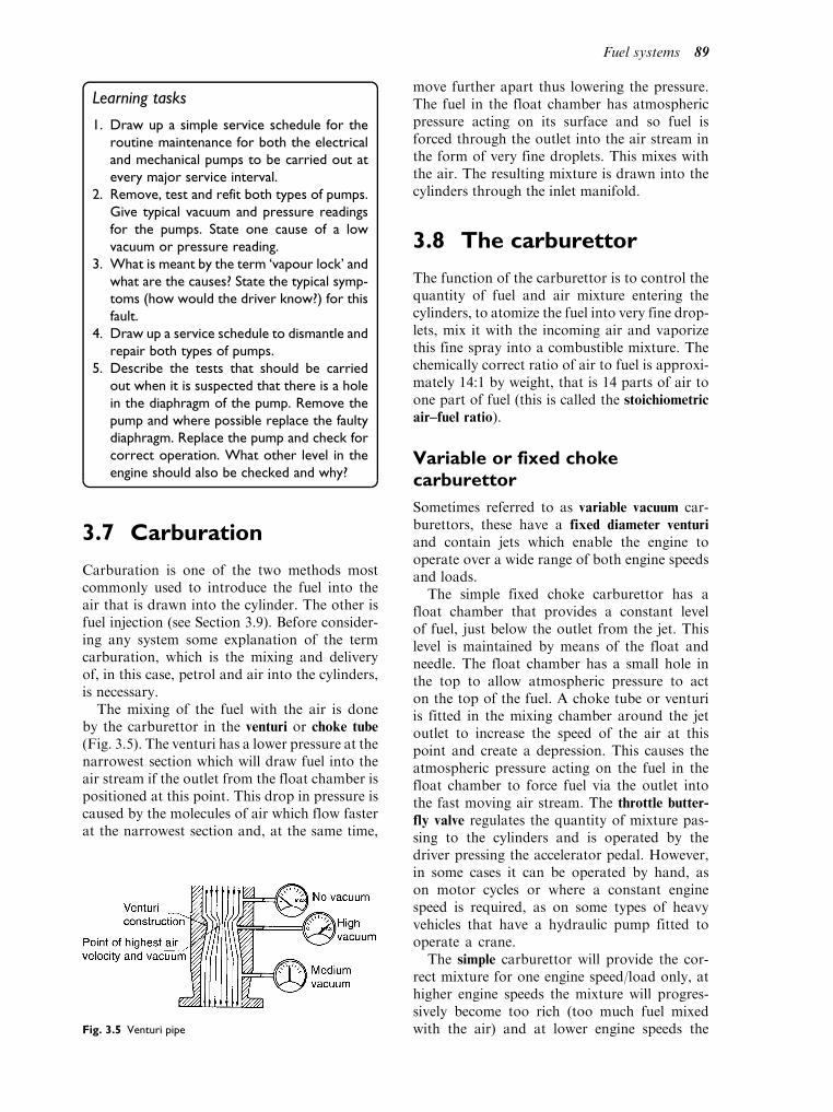
Learning tasks
1. Draw up a simple service schedule for the
routine maintenance for both the electrical
and mechanical pumps to be carried out at
every major service interval.
2. Remove, test and refit both types of pumps.
Give typical vacuum and pressure readings
for the pumps. State one cause of a low
vacuum or pressure reading.
3. What is meant by the term ‘vapour lock’ and
what are the causes? State the typical symp-
toms (how would the driver know?) for this
fault.
4. Draw up a service schedule to dismantle and
repair both types of pumps.
5. Describe the tests that should be carried
out when it is suspected that there is a hole
in the diaphragm of the pump. Remove the
pump and where possible replace the faulty
diaphragm. Replace the pump and check for
correct operation. What other level in the
engine should also be checked and why?
3.7 Carburation
Carburation is one of the two methods mostcommonly used to introduce the fuel into theair that is drawn into the cylinder. The other isfuel injection (see Section 3.9). Before consider-ing any system some explanation of the termcarburation, which is the mixing and deliveryof, in this case, petrol and air into the cylinders,is necessary.
The mixing of the fuel with the air is doneby the carburettor in the venturi or choke tube
(Fig. 3.5). The venturi has a lower pressure at thenarrowest section which will draw fuel into theair stream if the outlet from the float chamber ispositioned at this point. This drop in pressure iscaused by the molecules of air which flow fasterat the narrowest section and, at the same time,
move further apart thus lowering the pressure.The fuel in the float chamber has atmosphericpressure acting on its surface and so fuel isforced through the outlet into the air stream inthe form of very fine droplets. This mixes withthe air. The resulting mixture is drawn into thecylinders through the inlet manifold.
3.8 The carburettor
The function of the carburettor is to control thequantity of fuel and air mixture entering thecylinders, to atomize the fuel into very fine drop-lets, mix it with the incoming air and vaporizethis fine spray into a combustible mixture. Thechemically correct ratio of air to fuel is approxi-mately 14:1 by weight, that is 14 parts of air toone part of fuel (this is called the stoichiometric
air–fuel ratio).
Variable or fixed chokecarburettor
Sometimes referred to as variable vacuum car-burettors, these have a fixed diameter venturi
and contain jets which enable the engine tooperate over a wide range of both engine speedsand loads.
The simple fixed choke carburettor has afloat chamber that provides a constant levelof fuel, just below the outlet from the jet. Thislevel is maintained by means of the float andneedle. The float chamber has a small hole inthe top to allow atmospheric pressure to acton the top of the fuel. A choke tube or venturiis fitted in the mixing chamber around the jetoutlet to increase the speed of the air at thispoint and create a depression. This causes theatmospheric pressure acting on the fuel in thefloat chamber to force fuel via the outlet intothe fast moving air stream. The throttle butter-
fly valve regulates the quantity of mixture pas-sing to the cylinders and is operated by thedriver pressing the accelerator pedal. However,in some cases it can be operated by hand, ason motor cycles or where a constant enginespeed is required, as on some types of heavyvehicles that have a hydraulic pump fitted tooperate a crane.
The simple carburettor will provide the cor-rect mixture for one engine speed/load only, athigher engine speeds the mixture will progres-sively become too rich (too much fuel mixedwith the air) and at lower engine speeds theFig. 3.5 Venturi pipe
Fuel systems 89

mixture becomes too weak (that is not enoughfuel is mixed with the air). When starting fromcold a smaller proportion of fuel is evaporatedand some may condense onto the cold surfacesof the inlet manifold before reaching the com-bustion chamber. Because of this a mixturericher than the chemically correct ratio isrequired. As the engine revs are increased theflow rate of the air does not match that ofthe fuel and consequently the air/fuel mixturebecomes progressively too rich. Because ofthese problems the simple carburettor is notsuitable for the modern motor car, althoughthe basic principles of operation still apply. Thistype of carburettor is shown in Fig. 3.6.
Learning tasks
1. On which types of engines would the simple
carburettor be used? Give reasons for your
answer.
2. Give two reasons why a simple carburettor
is unsuitable for the modern motor vehicle.
3. Dismantle a simple carburettor. State how
many jets are fitted and what they are called.
Clean and reassemble the carburettor,
adjust the slow running jet and maximum
and minimum revs to suit the engine.
Mixture correction
The simple carburettor attempts to meter boththe fuel and the air. Air, which is a gas, flowsvery easily; petrol is a liquid which has particlesthat try to stick together and to the surface ofthe passages through which it must flow. If a
suitable size jet is used for a fixed engine speed/load then if the speed is increased the largerdepression would cause more fuel to flow creat-ing a rich mixture.
To overcome the problem of the mixture get-ting richer as the engine speed increases an airbleed is fitted in the system. Methods of mixturecorrection all use the same basic principle, i.e. asthe engine speed increases air is introduced intothe fuel system to gradually weaken the mixtureby reducing the amount of fuel entering theventuri. This gives a fairly constant mixturestrength over a wider range of engine speedsand is shown in Fig. 3.7(a).
Air bleed compensation
With this arrangement a well of petrol, fed fromthe main jet, is subject to the depression in theventuri. As the fuel level is lowered air bleed holes
are progressively uncovered, thereby admittingmore air which reduces the depression acting onthe jet which prevents enrichment of the mixtureas the depression in the venturi increases. Thetube, which contains a number of holes drilleddown its length, is sometimes called the emulsion
or diffuser tube as it tends to premix the fuel andair. The level in the well is at the same level as thefloat chamber when the engine is not running.Some systems have an air bleed jet (sometimescalled an air correction jet) to enable the size ofthe jet to be altered. This is for tuning purposesand under normal circumstances would not beremoved except for cleaning.
Slow-running (idling) systems
When the engine is running slowly, say at tick-over, the depression in the venturi is not highenough to draw fuel out of the main jet andatomize it into very fine droplets. The speed of
Fig. 3.6 Simple downdraught carburettor Fig. 3.7(a) Compensating jet action
90 A practical approach to motor vehicle engineering and maintenance
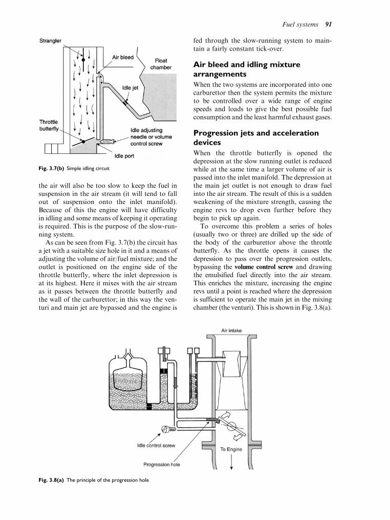
the air will also be too slow to keep the fuel insuspension in the air stream (it will tend to fallout of suspension onto the inlet manifold).Because of this the engine will have difficultyin idling and some means of keeping it operatingis required. This is the purpose of the slow-run-ning system.
As can be seen from Fig. 3.7(b) the circuit hasa jet with a suitable size hole in it and a means ofadjusting the volume of air/fuel mixture; and theoutlet is positioned on the engine side of thethrottle butterfly, where the inlet depression isat its highest. Here it mixes with the air streamas it passes between the throttle butterfly andthe wall of the carburettor; in this way the ven-turi and main jet are bypassed and the engine is
fed through the slow-running system to main-tain a fairly constant tick-over.
Air bleed and idling mixturearrangements
When the two systems are incorporated into onecarburettor then the system permits the mixtureto be controlled over a wide range of enginespeeds and loads to give the best possible fuelconsumption and the least harmful exhaust gases.
Progression jets and accelerationdevices
When the throttle butterfly is opened thedepression at the slow running outlet is reducedwhile at the same time a larger volume of air ispassed into the inlet manifold. The depression atthe main jet outlet is not enough to draw fuelinto the air stream. The result of this is a suddenweakening of the mixture strength, causing theengine revs to drop even further before theybegin to pick up again.
To overcome this problem a series of holes(usually two or three) are drilled up the side ofthe body of the carburettor above the throttlebutterfly. As the throttle opens it causes thedepression to pass over the progression outlets,bypassing the volume control screw and drawingthe emulsified fuel directly into the air stream.This enriches the mixture, increasing the enginerevs until a point is reached where the depressionis sufficient to operate the main jet in the mixingchamber (the venturi). This is shown in Fig. 3.8(a).
Fig. 3.7(b) Simple idling circuit
Fig. 3.8(a) The principle of the progression hole
Fuel systems 91
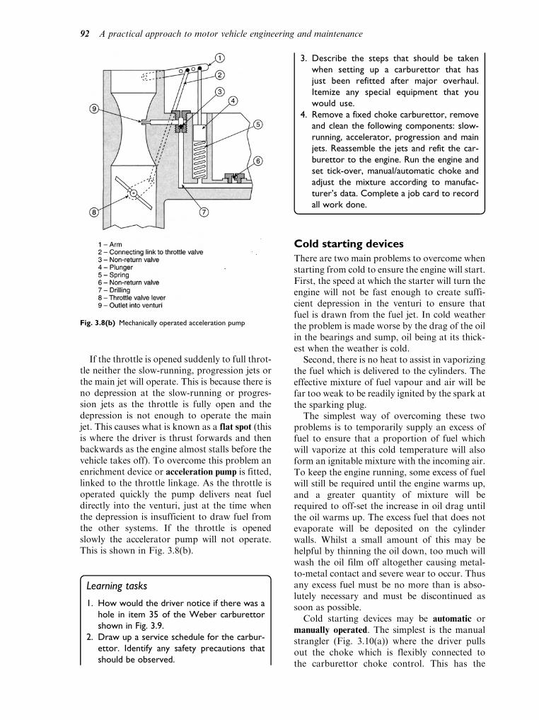
If the throttle is opened suddenly to full throt-tle neither the slow-running, progression jets orthe main jet will operate. This is because there isno depression at the slow-running or progres-sion jets as the throttle is fully open and thedepression is not enough to operate the mainjet. This causes what is known as a flat spot (thisis where the driver is thrust forwards and thenbackwards as the engine almost stalls before thevehicle takes off). To overcome this problem anenrichment device or acceleration pump is fitted,linked to the throttle linkage. As the throttle isoperated quickly the pump delivers neat fueldirectly into the venturi, just at the time whenthe depression is insufficient to draw fuel fromthe other systems. If the throttle is openedslowly the accelerator pump will not operate.This is shown in Fig. 3.8(b).
Learning tasks
1. How would the driver notice if there was a
hole in item 35 of the Weber carburettor
shown in Fig. 3.9.
2. Draw up a service schedule for the carbur-
ettor. Identify any safety precautions that
should be observed.
3. Describe the steps that should be taken
when setting up a carburettor that has
just been refitted after major overhaul.
Itemize any special equipment that you
would use.
4. Remove a fixed choke carburettor, remove
and clean the following components: slow-
running, accelerator, progression and main
jets. Reassemble the jets and refit the car-
burettor to the engine. Run the engine and
set tick-over, manual/automatic choke and
adjust the mixture according to manufac-
turer’s data. Complete a job card to record
all work done.
Cold starting devices
There are two main problems to overcome whenstarting from cold to ensure the engine will start.First, the speed at which the starter will turn theengine will not be fast enough to create suffi-cient depression in the venturi to ensure thatfuel is drawn from the fuel jet. In cold weatherthe problem is made worse by the drag of the oilin the bearings and sump, oil being at its thick-est when the weather is cold.
Second, there is no heat to assist in vaporizingthe fuel which is delivered to the cylinders. Theeffective mixture of fuel vapour and air will befar too weak to be readily ignited by the spark atthe sparking plug.
The simplest way of overcoming these twoproblems is to temporarily supply an excess offuel to ensure that a proportion of fuel whichwill vaporize at this cold temperature will alsoform an ignitable mixture with the incoming air.To keep the engine running, some excess of fuelwill still be required until the engine warms up,and a greater quantity of mixture will berequired to off-set the increase in oil drag untilthe oil warms up. The excess fuel that does notevaporate will be deposited on the cylinderwalls. Whilst a small amount of this may behelpful by thinning the oil down, too much willwash the oil film off altogether causing metal-to-metal contact and severe wear to occur. Thusany excess fuel must be no more than is abso-lutely necessary and must be discontinued assoon as possible.
Cold starting devices may be automatic ormanually operated. The simplest is the manualstrangler (Fig. 3.10(a)) where the driver pullsout the choke which is flexibly connected tothe carburettor choke control. This has the
Fig. 3.8(b) Mechanically operated acceleration pump
92 A practical approach to motor vehicle engineering and maintenance

effect of reducing the air supply and enrichingthe mixture drawn into the engine cylinders.
A simple automatic cold start control (Fig.3.10(b)) has a bi-metal spring wound round the
strangler (butterfly) spindle. One end of thespring is attached to the spindle; the other endis attached to the carburettor body in such away that the butterfly is held in the closed
Fig. 3.9 Weber 32IBA unit
Fuel systems 93
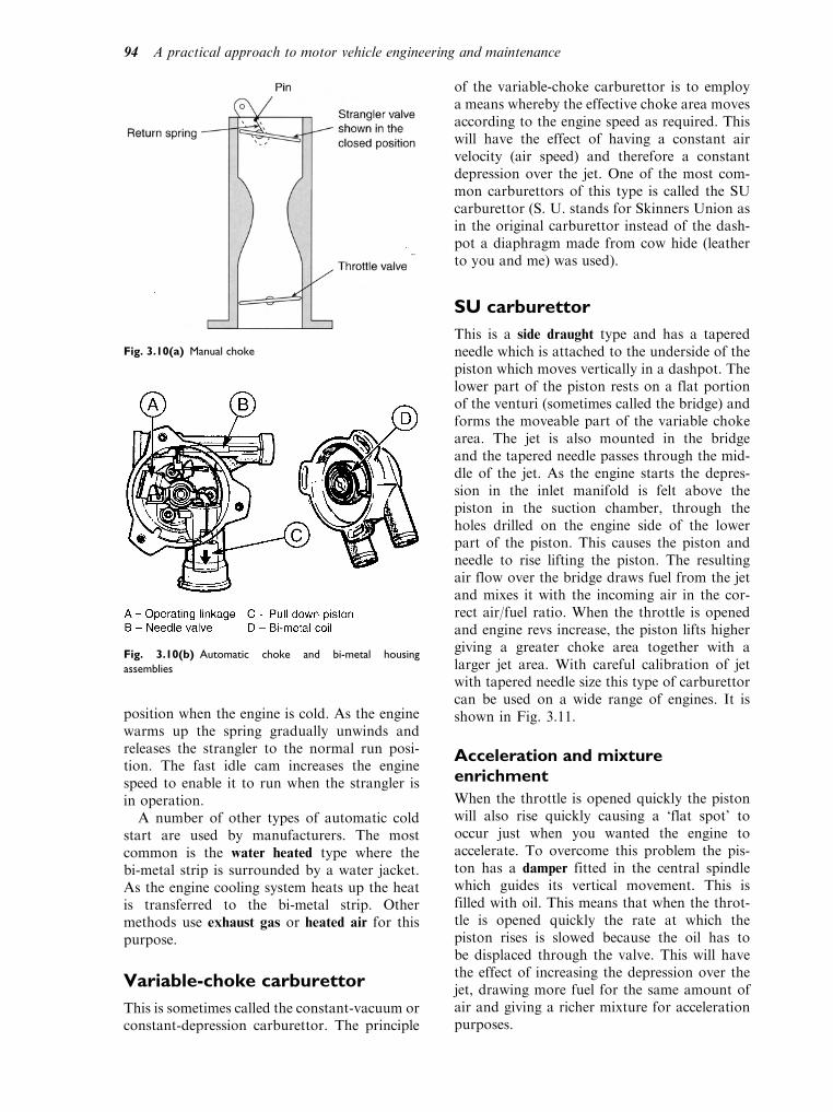
position when the engine is cold. As the enginewarms up the spring gradually unwinds andreleases the strangler to the normal run posi-tion. The fast idle cam increases the enginespeed to enable it to run when the strangler isin operation.
A number of other types of automatic coldstart are used by manufacturers. The mostcommon is the water heated type where thebi-metal strip is surrounded by a water jacket.As the engine cooling system heats up the heatis transferred to the bi-metal strip. Othermethods use exhaust gas or heated air for thispurpose.
Variable-choke carburettor
This is sometimes called the constant-vacuum orconstant-depression carburettor. The principle
of the variable-choke carburettor is to employa means whereby the effective choke area movesaccording to the engine speed as required. Thiswill have the effect of having a constant airvelocity (air speed) and therefore a constantdepression over the jet. One of the most com-mon carburettors of this type is called the SUcarburettor (S. U. stands for Skinners Union asin the original carburettor instead of the dash-pot a diaphragm made from cow hide (leatherto you and me) was used).
SU carburettor
This is a side draught type and has a taperedneedle which is attached to the underside of thepiston which moves vertically in a dashpot. Thelower part of the piston rests on a flat portionof the venturi (sometimes called the bridge) andforms the moveable part of the variable chokearea. The jet is also mounted in the bridgeand the tapered needle passes through the mid-dle of the jet. As the engine starts the depres-sion in the inlet manifold is felt above thepiston in the suction chamber, through theholes drilled on the engine side of the lowerpart of the piston. This causes the piston andneedle to rise lifting the piston. The resultingair flow over the bridge draws fuel from the jetand mixes it with the incoming air in the cor-rect air/fuel ratio. When the throttle is openedand engine revs increase, the piston lifts highergiving a greater choke area together with alarger jet area. With careful calibration of jetwith tapered needle size this type of carburettorcan be used on a wide range of engines. It isshown in Fig. 3.11.
Acceleration and mixtureenrichment
When the throttle is opened quickly the pistonwill also rise quickly causing a ‘flat spot’ tooccur just when you wanted the engine toaccelerate. To overcome this problem the pis-ton has a damper fitted in the central spindlewhich guides its vertical movement. This isfilled with oil. This means that when the throt-tle is opened quickly the rate at which thepiston rises is slowed because the oil has tobe displaced through the valve. This will havethe effect of increasing the depression over thejet, drawing more fuel for the same amount ofair and giving a richer mixture for accelerationpurposes.
Fig. 3.10(a) Manual choke
Fig. 3.10(b) Automatic choke and bi-metal housing
assemblies
94 A practical approach to motor vehicle engineering and maintenance
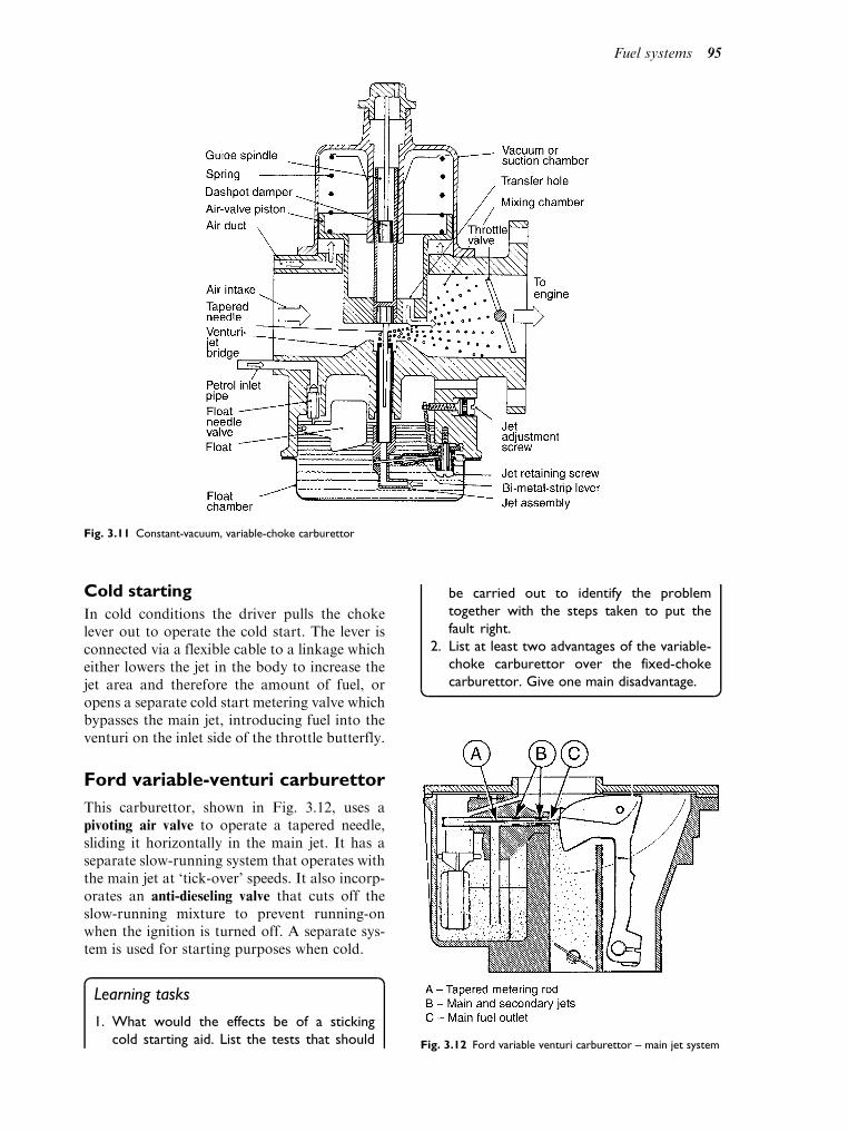
Cold starting
In cold conditions the driver pulls the chokelever out to operate the cold start. The lever isconnected via a flexible cable to a linkage whicheither lowers the jet in the body to increase thejet area and therefore the amount of fuel, oropens a separate cold start metering valve whichbypasses the main jet, introducing fuel into theventuri on the inlet side of the throttle butterfly.
Ford variable-venturi carburettor
This carburettor, shown in Fig. 3.12, uses apivoting air valve to operate a tapered needle,sliding it horizontally in the main jet. It has aseparate slow-running system that operates withthe main jet at ‘tick-over’ speeds. It also incorp-orates an anti-dieseling valve that cuts off theslow-running mixture to prevent running-onwhen the ignition is turned off. A separate sys-tem is used for starting purposes when cold.
Learning tasks
1. What would the effects be of a sticking
cold starting aid. List the tests that should
be carried out to identify the problem
together with the steps taken to put the
fault right.
2. List at least two advantages of the variable-
choke carburettor over the fixed-choke
carburettor. Give one main disadvantage.
Fig. 3.11 Constant-vacuum, variable-choke carburettor
Fig. 3.12 Ford variable venturi carburettor – main jet system
Fuel systems 95

3.9 Computer controlledpetrol fuelling systems
Computer controlled petrol injection is nowthe normal method of supplying fuel – in acombustible mixture form – to the engine’scombustion chambers. Although it is possibleto inject petrol direct into the engine cylinder,in a similar way to that which is used indiesel engines, the practical problems are dif-ficult to solve and it is still common practiceto inject (spray) petrol into the inductionmanifold. There are, broadly speaking, twoways in which injection into the inductionmanifold is performed. One way is to use asingle injector that sprays fuel into the regionof the throttle butterfly and the other way isto use an injector for each cylinder, eachinjector being placed near to the inlet valve.The two systems are known as single point
injection (throttle body injection) and multi-point injection. The principle is illustrated inFig. 3.13.
Computer controlled multi-pointfuel injection system
In petrol injection systems it is often the practiceto supply the injectors with petrol under pres-sure, through a fuel gallery or ‘rail’. Each injec-tor is connected to this gallery by a separatepipe, as shown in Fig. 3.14.
The pressure of the fuel in the gallery iscontrolled by a regulator of the type shown inFig. 3.15.
This particular pressure regulator is set dur-ing manufacture to give a maximum fuel pres-sure of 2.5 bar. In operation the petrol pumpdelivers more fuel than is required for injectionand the excess pressure lifts the regulator valve
(a)
1 (Injector)
2
Intakemanifold
Injector
Airintake
Cylinders
(b)
Airintake
Intakemanifold
Injectorsone per cylinder
2
1
Fig. 3.13 (a) Single-point injection, (b) Multi-point injection
96 A practical approach to motor vehicle engineering and maintenance

(5) off its seat to allow the excess fuel to returnto the fuel tank via the return connection (6).
The internal diaphragm (2) of the regulator issubject to inlet manifold pressure (vacuum) andthis permits the diaphragm and spring to regu-late fuel pressure to suit a range of operatingconditions. Raising the diaphragm against thespring lowers the fuel pressure and this permitsa low pressure of approximately 1.8 bar. Low-ering the diaphragm in response to higher pres-sure in the inlet manifold (wider throttleopening) gives a high fuel pressure of approxi-mately 2.5 bar.
With this arrangement, the amount of fuelthat each injector sprays into the inlet mani-fold is determined by the length of time forwhich the injector valve is opened by its oper-ating solenoid. By varying the length of timefor which the injector valve remains open, theamount of fuel injected suits a range ofrequirements.
Fuelling requirements for a particular engineare known to the designer and are placed in thecomputer (ECU) memory (ROM). In operation,the ECU receives information (data) from all ofthe sensors connected with the engine’s fuelneeds. The ECU compares the input data fromthe sensors with the data stored in the computermemory.
From this comparison of data, the ECUprovides some output data which appears onthe injector cables as an electrical pulse thatlasts for a set period. This injector electricalpulse time varies from approximately 2 milli-seconds (ms), to around 10ms. The ‘duty cycle’concept is based on the percentage of availabletime for which the device is energised, as shownin Fig. 3.16.
A fuelling map
The performance characteristics of the engineand the driveability of the vehicle are deter-mined by the ‘quality’ of the input that is put
Fig. 3.14 The fuel gallery
Fig. 3.15 The fuel pressure regulator
B A
C
C = 60 ms (100%)A = 15 ms (1/4 of 60 ms = 25%)B = 45 ms (3/4 of 60 ms = 75%)
A typical square waveform is shown in thefigure, a single cycle is indicated by 'C', whichconsists of an ON time 'A', and an OFF time 'B'.
Duty cycle is the length of the ON time 'A'compared to the whole cycle 'C', expressed as apercentage. (Please note, On time can be Highand Low on certain systems.) Using the figure and the time periods, the dutycycle is 25%.
Fig. 3.16 Duty cycle
Fuel systems 97

into the design and part of this design is thecomputer program that is held in the readonly memory (ROM) of the ECM. A fuellingmap is shown in Fig. 3.17. The variables onthe three axis of this graph (map) are engineload, engine speed and air–fuel ratio. For eachcombination of engine speed and load there isa corresponding air–fuel ratio where the pointsmeet on the surface of the map. Each of thesepoints can be represented by a binary codeand it is a range of points from the map thatit is stored in the ROM of the ECM. Thevalues stored in the ROM are compared withinput signals from sensors in order that thecomputer can determine the duration of thefuel injection pulse.
Some computerised systems are designed sothat the franchised dealership can alter the com-puter program to match customer requirements.A re-programmable ROM is necessary for thisto be done and the work can only be done byqualified personnel acting under the control ofthe vehicle manufacturer.
Single point injection
In its simplest from, petrol injection consists ofa single injector that sprays petrol into theinduction manifold, in the region of the throttlebutterfly valve, as shown at (4) in Fig. 3.18.
Finely atomised fuel is sprayed into the throttlebody, in accordance with controlling actions
from the engine computer, thus ensuring thatthe correct air–fuel ratio is supplied to the com-bustion chambers to suit all conditions. The par-ticular system shown here uses the speed densitymethod of determining the mass of air that isentering the engine, rather than the air flowmeterthat is used in some other applications. In orderfor the computer to work out (compute) theamount of fuel that is needed for a given set of
z
High
Engine load
LowEngine speed RPM10002000
30004000
5000x
λ ai
r fu
el r
atio
y
Fig. 3.17 An engine fuelling map
1. Fuel pressure regulator2. Throttle position sensor3. Air charge temperature sensor4. Injector valve5. Throttle plate control motor (actuator)6. Throttle plate7. Engine
1
2
7
6
5
4
3
Fig. 3.18 Single-point injection details
98 A practical approach to motor vehicle engineering and maintenance
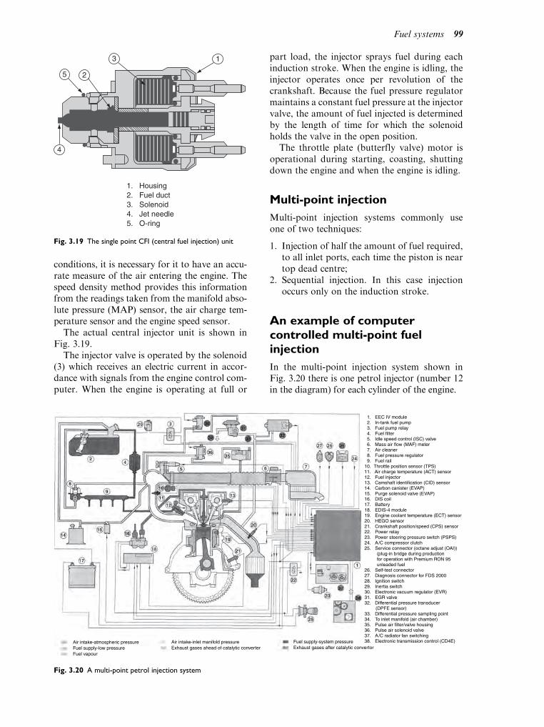
conditions, it is necessary for it to have an accu-rate measure of the air entering the engine. Thespeed density method provides this informationfrom the readings taken from the manifold abso-lute pressure (MAP) sensor, the air charge tem-perature sensor and the engine speed sensor.
The actual central injector unit is shown inFig. 3.19.
The injector valve is operated by the solenoid(3) which receives an electric current in accor-dance with signals from the engine control com-puter. When the engine is operating at full or
part load, the injector sprays fuel during eachinduction stroke. When the engine is idling, theinjector operates once per revolution of thecrankshaft. Because the fuel pressure regulatormaintains a constant fuel pressure at the injectorvalve, the amount of fuel injected is determinedby the length of time for which the solenoidholds the valve in the open position.
The throttle plate (butterfly valve) motor isoperational during starting, coasting, shuttingdown the engine and when the engine is idling.
Multi-point injection
Multi-point injection systems commonly useone of two techniques:
1. Injection of half the amount of fuel required,to all inlet ports, each time the piston is neartop dead centre;
2. Sequential injection. In this case injectionoccurs only on the induction stroke.
An example of computercontrolled multi-point fuelinjection
In the multi-point injection system shown inFig. 3.20 there is one petrol injector (number 12in the diagram) for each cylinder of the engine.
1. Housing2. Fuel duct3. Solenoid4. Jet needle5. O-ring
1
4
2
3
5
Fig. 3.19 The single point CFI (central fuel injection) unit
1. EEC IV module 2. In-tank fuel pump 3. Fuel pump relay 4. Fuel filter 5. Idle speed control (ISC) valve 6. Mass air flow (MAF) meter 7. Air cleaner 8. Fuel pressure regulator 9. Fuel rail10. Throttle position sensor (TPS)11. Air charge temperature (ACT) sensor 12. Fuel injector13. Camshaft identification (CID) sensor 14. Carbon canister (EVAP)15. Purge solenoid valve (EVAP)16. DIS coil17. Battery18. EDIS-4 module19. Engine coolant temperature (ECT) sensor 20. HEGO sensor21. Crankshaft position/speed (CPS) sensor 22. Power relay23. Power steering pressure switch (PSPS)24. A /C compressor clutch25. Service connector (octane adjust (OAI)) (plug-in bridge during production for operation with Premium RON 95 unleaded fuel26. Self-test connector27. Diagnosis connector for FDS 200028. Ignition switch29. Inertia switch30. Electronic vacuum regulator (EVR)31. EGR valve32. Differential pressure transducer (DPFE sensor)33. Differential pressure sampling point34. To inlet manifold (air chamber)35. Pulse air filter/valve housing36. Pulse air solenoid valve37. A /C radiator fan switching38. Electronic transmission control (CD4E)Air intake-atmospheric pressure
Fuel supply-low pressureFuel vapour
Air intake-inlet manifold pressureExhaust gases ahead of catalytic converter
Fuel supply-system pressureExhaust gases after catalytic convertor
Fig. 3.20 A multi-point petrol injection system
Fuel systems 99

Each of the injectors is designed so that itsprays fuel on to the back of the inlet valve.The actual position and angle at which injec-tion takes place varies for different types ofengines.
In the system shown in Fig. 3.20, the air flowis measured by the hot-wire type of mass airflow meter. The control computer receives thesignal from the air flow meter and uses thissignal together with those from other sensorssuch as engine speed, engine coolant tempera-ture, throttle position, etc., to determine thelength of time of the injection pulse.
Sequential multi-point injection
Sequential multi-point injection is a term that isused to describe the type of petrol injectionsystem that provides one injection of fuel foreach cylinder during each cycle of operation.To assist in providing the extra controllinginput that is required for sequential injection,the engine is fitted with an additional sensorwhich is driven by the engine camshaft. Halltype sensors and variable reluctance sensors dri-ven by the camshaft are often used for thispurpose which is to assist the computer to deter-mine TDC on number 1 cylinder. Figure 3.21shows one of these sensors which is fitted to anoverhead camshaft engine.
Some of the sensors used for fuelling are thesame as those used for ignition systems, forexample, crank speed and top dead centre sen-sors, manifold pressure to indicate engine load,etc. Because some of the sensor signals can be
used for both ignition and fuelling, it hasbecome common practice to place them underthe control of a single computer and the result-ing system is known as an engine managementsystem.
3.10 Engine managementsystems (EMS)
Engine management systems are designed tomake the vehicle comply with emissions regu-lations as well as to provide improved perfor-mance. This means that the number of sensorsand actuators is considerably greater than fora simple fuelling or ignition system. The sys-tem shown in Fig. 3.20 is fairly typical ofmodern engine management systems andselected items of technology from the list arepicked out to give them closer attention, sothat the aim of ‘teasing out’ features that theyhave in common with other components isrealised. The ignition system also forms partof an engine management system is coveredseparately in Chapter 10. The intention hereis to focus on some of the components in Fig.3.20. The first component to note is the oxy-gen sensor at 20. This is a heated sensor(HEGO) and the purpose of the heating ele-ment is to bring the sensor to its workingtemperature as quickly as possible. The func-tion of the HEGO is to provide a feedbacksignal that enables the ECM to control thefuelling so that the air–fuel ratio is keptclose to the chemically correct value whereLambda¼ 1, this value enabling the catalyticconvertor to function at its best. Oxygen sen-sors are common to virtually all modern petrolengined vehicles and this is obviously an areaof technology that technicians need to knowabout. The zirconia type oxygen sensor is mostcommonly used and it produces a voltage sig-nal that represents oxygen levels in the exhaustgas and is thus a reliable indicator of the air–fuel ratio that is entering the combustionchamber. The voltage signal from this sensoris fed back to the control computer to enableit to hold Lambda close to 1.
Exhaust catalyst conditionmonitoring
Vehicles that are equipped to the EuropeanOn Board Diagnostics (EOBD) standard have
1. CID
3. Inlet camshaft
2. Retaining screw
4. Reference lobe
4
3
1
2
Fig. 3.21 A cylinder identification sensor
100 A practical approach to motor vehicle engineering and maintenance
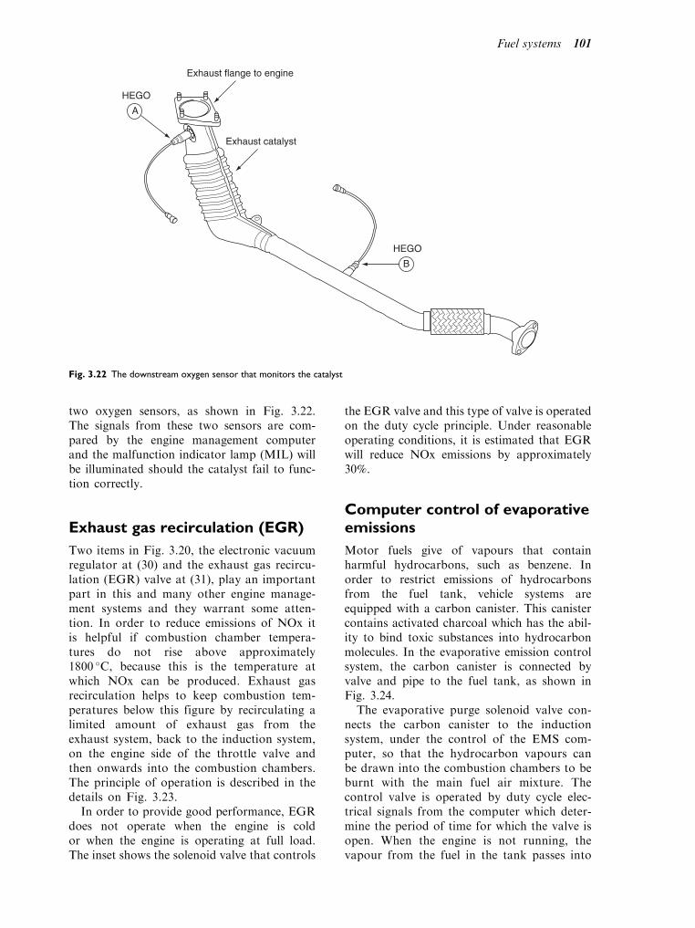
two oxygen sensors, as shown in Fig. 3.22.The signals from these two sensors are com-pared by the engine management computerand the malfunction indicator lamp (MIL) willbe illuminated should the catalyst fail to func-tion correctly.
Exhaust gas recirculation (EGR)
Two items in Fig. 3.20, the electronic vacuumregulator at (30) and the exhaust gas recircu-lation (EGR) valve at (31), play an importantpart in this and many other engine manage-ment systems and they warrant some atten-tion. In order to reduce emissions of NOx itis helpful if combustion chamber tempera-tures do not rise above approximately1800 C, because this is the temperature atwhich NOx can be produced. Exhaust gasrecirculation helps to keep combustion tem-peratures below this figure by recirculating alimited amount of exhaust gas from theexhaust system, back to the induction system,on the engine side of the throttle valve andthen onwards into the combustion chambers.The principle of operation is described in thedetails on Fig. 3.23.
In order to provide good performance, EGRdoes not operate when the engine is coldor when the engine is operating at full load.The inset shows the solenoid valve that controls
the EGR valve and this type of valve is operatedon the duty cycle principle. Under reasonableoperating conditions, it is estimated that EGRwill reduce NOx emissions by approximately30%.
Computer control of evaporativeemissions
Motor fuels give of vapours that containharmful hydrocarbons, such as benzene. Inorder to restrict emissions of hydrocarbonsfrom the fuel tank, vehicle systems areequipped with a carbon canister. This canistercontains activated charcoal which has the abil-ity to bind toxic substances into hydrocarbonmolecules. In the evaporative emission controlsystem, the carbon canister is connected byvalve and pipe to the fuel tank, as shown inFig. 3.24.
The evaporative purge solenoid valve con-nects the carbon canister to the inductionsystem, under the control of the EMS com-puter, so that the hydrocarbon vapours canbe drawn into the combustion chambers to beburnt with the main fuel air mixture. Thecontrol valve is operated by duty cycle elec-trical signals from the computer which deter-mine the period of time for which the valve isopen. When the engine is not running, thevapour from the fuel in the tank passes into
Exhaust flange to engine
Exhaust catalyst
HEGO
B
A
HEGO
Fig. 3.22 The downstream oxygen sensor that monitors the catalyst
Fuel systems 101

the carbon canister and when the engine isstarted up, the engine management computerswitches on the solenoid valve so that thevapour can pass into the induction system.After this the frequency of operation of thesolenoid valve is dependent on operatingconditions.
Evaporative emissions control is part of theemissions control system of the vehicle and itmust be maintained in good order.
3.11 Maintenance andrepair of petrol fuelsystems
Safety
Before commencing any work that entailsremoval of fuel system components precautionsmust be taken to prevent fire. In addition tomanufacturers recommendations the followingshould be noted:
. Have a fire extinguisher close to hand;
. Take precautions to avoid sparks;
. De-pressurise the system;
. Avoid petrol spillage;
. Use protective eye wear;
. Familiarise yourself with steps to take in theevent of petrol spillage; and
. Ensure that fume extraction equipment isoperational.
Carburettor systems
The function of a carburettor system is to sup-ply the engine with a combustible mixture of thecorrect air–fuel ratio to suit all conditions inwhich the vehicle is required to operate. Failureto produce the correct type and amount of mix-ture will lead to a variety of problems, such aspoor starting or failure to start, poor idling,hesitation and misfire on acceleration, lack ofpower, excessive fuel consumption, emissionsout of limits, etc.
Fuel system problems are normally associatedwith the two substances that make up the com-bustible mixture, namely air and fuel. Too muchair and insufficient fuel causes weak mixtures,and too little air and too much petrol leads torich mixtures. Both of these conditions causeengine operating problems and an understand-ing of the probable causes of these extremeconditions is a helpful step towards finding asolution to a petrol fuel system problem.
Fig. 3.23 Exhaust gas recirculation system
102 A practical approach to motor vehicle engineering and maintenance

Air supply problems –carburettor fuel system
Fuel supply problems –carburettor fuel system
Fig. 3.24 Evaporative emissions control system
Defect Possible causes
Insufficient air Blocked air filter, air filter element fitted
badly. Damaged or blocked air intake
Excess air Air leaks into intake manifold from brake
servo pipe or vacuum advance pipe for
ignition distributor
Broken or warped carburettor and or
manifold flanges. Loose fixing bolts.
Broken gaskets.
Worn throttle butterfly spindle and bushes.
Defective crankcase ventilation
Defect Possible causes
Rich mixture – excess fuel Petrol level high in float chamber.
Leaking needle valve.
Excessive petrol pressure.
Incorrect jets.
Mixture setting incorrect in
constant vacuum carburettor.
Punctured float
Weak mixture –
insufficient fuel
Blocked filter.
Incorrect mixture setting.
Pump delivery rate low.
Fuel pump pressure low
Fuel systems 103

Adjustments – carburettor
Carburettor idle mixtureadjustment (constant choke type)
Two types of idle mixture adjustment are used inconstant choke carburettors. One type varies thequality of the idle mixture by adjusting theamount of air that flows through the idling pas-sage of the carburettor, shown in Fig. 3.25(a).The other type, shown in Fig. 3.25(b), fixes theair–fuel ratio of the idle mixture by means ofpetrol and air jets and the idle adjustment variesthe quantity of mixture entering the engine.
Outline procedure for adjustmentof idling speed
To adjust engine idle settings:
. The engine must be at normal operatingtemperature;
. Workshop exhaust extraction operating;
. Tachometer and gas analyser connected;
. Cold start choke in off position;
. Throttle stop screw should be adjusted to givethe correct speed;
. Idling mixture screws should be adjusted toachieve the correct CO setting; and smoothoperation of the engine.
When the CO setting is correct it may be neces-sary to reset the idling speed.
Adjusting CO level and idle speed –petrol injection [Early models ofvehicles]
When engines have been in use for some time,and when new parts have been fitted, it may benecessary to adjust the engine idling settings toensure that CO levels in the exhaust gas arewithin the manufacturer’s specification. The pro-cedure for adjusting CO settings and idle speedon petrol injection systems varies considerablyacross the range of modern vehicles and it is
Air Idle mixtureadjusting screw
Idle mixturepetrol jet
Petrol fromfloat chamber
Idlingmixture
(a)
4
5
7 6 8
9
4. Idle petrol jet5. Idle air jet7. Idle quantity adjustment screw
(b)
Fig. 3.25 Quality control of idle mixture
104 A practical approach to motor vehicle engineering and maintenance

essential that details of the procedure for anygiven vehicle are known, or are readily available.The following example outlines the procedure forone particular system and it is intended to pro-vide an insight into the procedure.
The two screws marked A and B in Fig. 3.26 areprovided so that idle speed and mixture strength(CO level) may be adjusted. The screwA varies thesize of the throttle by-pass passage through whichthe air for idling passes and thus controls engineidle speed. The screw at B varies the size of the airflow meter by-pass and effectively controls themixture strength for idling purposes.
Equipment required
. Exhaust extraction system
. Manufacturer’s special tools and data shouldbe to hand
. Tachometer
. Exhaust gas analyser
. Small tools
Procedure
. Observe safety precautions;
. Have tools and equipment to hand;
. With the engine at normal operating tem-perature and electrical loads switched off, orset as per instructions, and the tachometerand gas analyser connected, the engine is firstchecked for engine speed and CO reading. Ifadjustment is required, the screws at A and Bare adjusted to give correct engine speed andCO level, with checks being made to ensurethat the engine is running smoothly.
Learning task
Study the section of a workshop manual that
describes the procedure for adjusting the CO
level on one type of vehicle that is commonly
worked on at your place of work.
Idling settings on enginemanagement systems (EMS)
In the type of engine management system shownin Fig. 3.20, engine idle conditions are con-trolled by the computer (EEC IV module). Inresponse to sensor signals, the computer adjuststhe idle control valve and alters the ignitionsetting to maintain stable engine operation.Over a period of time, component wear maycause the EMS computer to adopt new settingsfor idling speed and ignition timing. Should thisoccur and new components, such as an idlecontrol valve, be fitted, it will be necessary touse a manufacturer’s dedicated equipment tore-set the computer memory so that correctengine idling is restored.
Some other petrol fuel systemmaintenance procedures
Carburettor system
Routine maintenance
Fuel system maintenance is part of the routinemaintenance schedule of a vehicle. Factors suchas cleaning fuel filters and replacing air filters,
12a11
10
9
12
14
A
B
Fig. 3.26 Idling adjustments
Fuel systems 105

checking and servicing carbon canisters, togetherwith visual checks of electrical connections, nor-mally ensure that the fuel system is kept in goodworking condition.
Petrol injection system
Routine maintenance
Routine maintenance should include visualchecks of electrical circuits and connectionsand also similar checks of fuel lines. Mileagebased servicing will include renewal of air filters,servicing the carbon canister, inspecting andcleaning or renewing and fuel filters.
Since the introduction of European On BoardDiagnostics (EOBD), all emissions related func-tions, such as the fuel system, are constantlymonitored by the engine computer (ECM).In the event of a defect in part of the fuel system,the malfunction indicator lamp (MIL) willalert the driver and fault codes will be storedin the computer. If the fuel system is properlymaintained in accordance with the manufac-turer’s recommendation, problems with the fuelsystem should be a rare occurrence.
Other maintenance and repair
Whilst fault codes may not provide a com-plete answer to a fuel system problem, theyare extremely useful in guiding one to thegeneral area of the fault. In the event of apetrol injection fuel system failure, it may benecessary to conduct further tests. The testsshown here deal with mechanical aspectsnamely, fuel pressure and injector condition.Electrical tests are covered in the electricalsections of this book.
Safety
Please refer to Section 3.9
Fuel gallery pressure
The quantity of fuel injected is dependent on thefuel pressure being accurately maintained atthe level specified by the manufacturer. Thepressure may be checked by placing an accuratepressure gauge in the main fuel line.
Before attempting to connect the pressuregauge, the system fuel system must be de-pressurised and all precautions taken to preventspillage. This procedure varies from vehicle tovehicle and the manufacturer’s advice must beobserved. Once the gauge is connected and alltraces of petrol have been removed, the testprocedure may then be followed and the pres-sure should fall within the prescribed limits, ofthe order of 2.5 bar to 3 bar. This figure is only aguide; the manufacturer’s figures are the onesthat must be used in any particular case.Figure 3.27 shows a pressure gauge positionedat the outlet from the fuel filter.
Petrol injector testing
Figures 3.28(a),(b) show examples of two teststhat are possible on a vehicle. Again, theseshould only be undertaken by competent per-sonnel who are in possession of the necessaryinstructions and who are careful to take allnecessary safety precautions.
Figure 3.28(a) illustrates the type of test thatcan be performed to check for injector leakage.The injectors are removed from the manifoldand securely placed over drip trays. Note thatthey remain connected to the fuel and electricalsystem. The approved procedure is then applied
FilterPressuregauge
Petrol pipefrom tank
XM0272
Adaptor
Fig. 3.27 Fuel line pressure test
106 A practical approach to motor vehicle engineering and maintenance

to energise the injectors and a careful visualinspection will reveal if there are any leaks. Inthe case shown, it is recommended that anyinjector that leaks more than two drops of fuelper minute should be replaced.
Figure 3.28(b) shows the same injectors. In thiscase, three of them are disconnected and theamount of fuel delivered by the injector, which isstill connected, is carefully measured. It is possibleto obtain special injector test benches on whichthese tests can be performed, in ideal conditions.
In many applications, the petrol injectors canbe activated, by the diagnostic tester, throughthe serial port. This makes it possible to hear theinjectors ‘click’ as they are pulsed. If the fuelsupply is active during this process, a certainamount of fuel will enter the intake manifold.
In order to prevent damage to the exhaust cata-lyst, steps must be taken to prevent the fuelpassing through the engine and one procedureadvocates cranking the engine over with thespark plugs removed, to expel the unburnt fuel,on completion of the injector test.
Learning tasks
1. Draw up a service schedule for the complete
fuel system of a petrol injection vehicle. Item-
ize any specialized equipment that should be
used to complete the task.
2. Complete an exhaust gas test on a
petrol engine vehicle fitted with fuel injection.
Adjust the CO to give the correct reading
according to the manufacturer’s data.
Fig. 3.28 The general principle of a petrol injector test. (a) Testing injectors for leakage, (b) Testing the amount of fuel per injector
Fuel systems 107
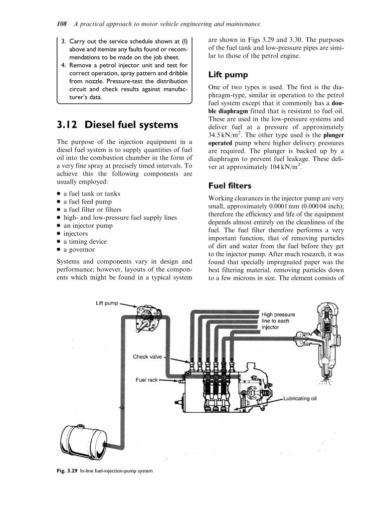
3. Carry out the service schedule shown at (I)
above and itemize any faults found or recom-
mendations to be made on the job sheet.
4. Remove a petrol injector unit and test for
correct operation, spray pattern and dribble
from nozzle. Pressure-test the distribution
circuit and check results against manufac-
turer’s data.
3.12 Diesel fuel systems
The purpose of the injection equipment in adiesel fuel system is to supply quantities of fueloil into the combustion chamber in the form ofa very fine spray at precisely timed intervals. Toachieve this the following components areusually employed:
. a fuel tank or tanks
. a fuel feed pump
. a fuel filter or filters
. high- and low-pressure fuel supply lines
. an injector pump
. injectors
. a timing device
. a governor
Systems and components vary in design andperformance; however, layouts of the compon-ents which might be found in a typical system
are shown in Figs 3.29 and 3.30. The purposesof the fuel tank and low-pressure pipes are simi-lar to those of the petrol engine.
Lift pump
One of two types is used. The first is the dia-phragm-type, similar in operation to the petrolfuel system except that it commonly has a dou-
ble diaphragm fitted that is resistant to fuel oil.These are used in the low-pressure systems anddeliver fuel at a pressure of approximately34.5 kN/m2. The other type used is the plunger
operated pump where higher delivery pressuresare required. The plunger is backed up by adiaphragm to prevent fuel leakage. These deli-ver at approximately 104 kN/m2.
Fuel filters
Working clearances in the injector pump are verysmall, approximately 0.0001mm (0.000 04 inch);therefore the efficiency and life of the equipmentdepends almost entirely on the cleanliness of thefuel. The fuel filter therefore performs a veryimportant function, that of removing particlesof dirt and water from the fuel before they getto the injector pump. After much research, it wasfound that specially impregnated paper was thebest filtering material, removing particles downto a few microns in size. The element consists of
Fig. 3.29 In-line fuel-injection-pump system
108 A practical approach to motor vehicle engineering and maintenance

the specially treated paper wound around a cen-tral core in a spiral form, enclosed in a thin metalcanister giving maximum filtration within mini-mum overall dimension.
Most filters are of the agglomerator type(Fig. 3.31), i.e. as the fuel passes through the
element, water, which is always present, issqueezed out of the fuel and agglomerates (joinstogether) into larger droplets which then settle tothe base of the filter by sedimentation. Chokingof the filters is caused not only by the solid matterheld back by the element but also by the sludge
Fig. 3.30 (a) The basic components of a diesel fuel system are a fuel tank, lift pump with priming lever, fuel filter, injection pump,
injector pipes and injectors. Additonal pipes connected to the injection pump and injectors return excess fuel to the fuel tank,
(b) Distributor-type fuel injection pump
Fuel systems 109

and wax in the fuel which, under very cold con-ditions, form a coating on the surfaces of the fuelfilter element thus reducing the rate of fuel flow.Where this becomes too much of a problem asimple sedimenter-type filter, i.e. one which doesnot incorporate an element, is fitted between thefuel tank and the lift pump. The object of a simplesedimenter is to separate the larger particles ofdirt, wax and water from the fuel; they are thenperiodically drained off. Provision is made for theventing of the filter of air (this is commonly calledbleeding the system, where all the air in the fuelsystem is removed). If air enters the high-pressurefuel lines then the engine will not run.
Learning tasks
1. Remove and refit the fuel filter on a diesel
engine vehicle, bleed the system and run the
engine.
2. Remove and refit the lift pump of a diesel
system, test the operation of the pressure/
vacuum valves, record results and check
with the manufacturer’s data. Give reasons
for any differences and make recommenda-
tions to the customer on serviceability.
3. Draw up a simple checklist for tracing leaks
on a diesel fuel system.
4. Make a list of personal safety/hygiene pre-
cautions that a mechanic should consider
when working on a diesel fuel system.
5. What are the symptoms of a blocked fuel
filter?
6. What are the service intervals for the diesel
fuel system and what would it involve?
Injector pump
The function of the injector pump is to:
. deliver the correct amount of fuel;
. at the correct time;
. at sufficiently high a pressure to enable theinjector to break up the fuel into very finedroplets to ensure complete combustion (thatis complete burning of all the fuel injected).
The multi-element or the DPA (distributorpump application) injector pumps are the onesmost commonly used.
Multi-element injector pump
This consists of a casing containing the samenumber of pumping elements as there are cylin-ders in the engine. Each element consists of aplunger and barrel machined to very fine toler-ances, and specially lapped together to form amated pair. A helix (similar to a spiral) isformed on the outside of the plunger whichcommunicates with the plunger crown, either
Fig. 3.31 Bowless-type filter-agglomerator-sedimenter showing agglomerator flow through element
110 A practical approach to motor vehicle engineering and maintenance

by a drilling in the centre of the plunger or a slotmachined in the side. There are two ports in thebarrel, both of which connect to a common fuelgallery feeding all the elements. The plunger isoperated by a cam and follower tappet andreturned by a spring. This system is shown inFig. 3.32.
When the plunger is at BDC, fuel entersthrough the barrel ports filling the chamberabove, and also the machined portion formingthe helix of the plunger. As the plunger rises,it will reach a point when both ports are effec-tively cut off (this is known as spill cut-off
point and is the theoretical start of injection).
Fig. 3.32 CAV (‘Minimec’) in-line injection pump
Fuel systems 111

Further upward movement of the plungerforces the fuel through the delivery valve, injec-tor pipes and injectors into the combustionchamber. With the plunger stroke being con-stant, any variation in the amount of fuelbeing delivered is adjusted by rotating theplunger causing the helix to uncover the spillport sooner or later depending on rotation.Immediately the helix uncovers the spill port,the fuel at high pressure above the plungerspills back to the common gallery, the deliveryvalve resumes its seat and injection stops with-out any fuel dribbling from the injector. Eachinjector is rotated simultaneously by a rack orcontrol rod. No fuel or engine stop position isobtained by rotating the plunger so that thehelix is always in alignment with the ports inthe barrel, in this position, pressure cannotbuild up and hence no fuel will be delivered.Figure 3.33 illustrates this.
Delivery valve
The purpose of a delivery valve (Fig. 3.34) beingfitted above each element is to:
. prevent fuel being drawn out of the injectorpipe on the downward stroke of the plunger;
. ensure a rapid collapse of the pressure wheninjection ceases, thus preventing fuel fromdribbling from the injector;
. maintain a residual pressure in the injectorpipes.
The valve and guide of the delivery valve aremachined to similar tolerances as the pumpingelements. Approximately two thirds of the valveis machined to form longitudinal grooves. Abovethe grooves is the unloading collar; immediatelyabove the collar is the valve seat. When the pumpis on the delivery stroke, fuel pressure rises andthe delivery valve moves up until the fuel canescape through the longitudinal grooves. Imme-diately the plunger releases the fuel pressure inthe barrel, the delivery valve starts to resume itsseat under the influence of the spring and thedifference in the pressure above and below thevalve. As the unloading collar enters the guidesdividing the element from the delivery pipe,further downwards movement increases thevolume above the valve (by an amount equal tothe volume between the unloading collar and thevalve seat). The effect of this increase in volume isto suddenly reduce the pressure in the injectionpipe so that the nozzle valve ‘snaps’ closed ontoits seat thus instantaneously terminating injectionwithout dribble.
Excess fuel device
Multi-element injection pumps are normallyfitted with an excess fuel device which, whenoperated, allows the pumping elements todeliver fuel in excess of normal maximum.This ensures that the delivery pipes from theinjection pump to the injectors are quickly
Fig. 3.33 Plunger and barrel. (a) Pumping
element filling, (b) Injection, (c) Spill: no
fuel out
112 A practical approach to motor vehicle engineering and maintenance

primed if the engine has not been run forsome time or if assistance is needed for easystarting in cold conditions. When the deviceis operated (with the engine stationary), therack or control rod of the fuel injectionpump moves to the excess position under thepressure of the governor spring. On operating
the starter, excess fuel is delivered to theengine. As soon as the engine starts, governoraction moves the control rod towards theminimum fuel position making the deviceinoperative.
Cam shapes
To prevent the possibility of reverse running, itis normal practice to fit a camshaft with pro-files designed so that the plunger is at TDC forapproximately two-thirds of a revolution. Inthe event of a back-fire the engine will notrun. Certain CAV pumps are fitted with rever-sible type camshafts. In order to preventreverse running, a spring-loaded coupling, simi-lar to the pawl-type free-wheel is fitted betweenthe pump and the engine. Figure 3.35 shows acam profile.
Phasing and calibration
Phasing is a term used when adjustment ismade to ensure injection occurs at the correcttime, i.e. on four-cylinder engines each elementinjects at 90 intervals while on a six-cylinder
Fig. 3.34 Delivery-valve action
Fig. 3.35 Sectioned view showing
cam profile
Fuel systems 113

engine each element injects at 60 intervals.This adjustment is carried out by raising orlowering the plunger so the spill cut-off pointis reached at the correct time. Simms pumpshave spacers in the tappet blocks (Fig. 3.34).CAV pumps have normal tappet adjustment.Phasing should not be confused with spill tim-ing (this is when the injection pump is timedto the engine).
Calibration refers to the amount of fuel thatis injected. Correct calibration ensures that thesame amount of fuel is injected by each ele-ment at a given control rod setting. It iseffected by rotating the plunger independentlyof the control rod. Both phasing and calibra-tion can only be carried out on proper equip-ment and using data sheets to obtain speedand fuel delivery settings for any giveninjection pump. When settings are adjustedcorrectly the maximum fuel stop screw issealed and must not be adjusted under anycircumstances.
Lubrication
The delivery valves and pumping elements arelubricated by the fuel oil, a small quantity ofwhich leaks past the plunger and barrel into thecambox. The camshaft, bearings, tappets, etc.are lubricated by engine oil contained in thecambox. To prevent a build-up of oil due tothe fuel leaking past the elements, the level plugincorporates a leak-off pipe.
Spill timing the multi-elementpump to the engine
After mounting the injection pump to the engineand checking that the alignment and drive
coupling clearance are correct, it is necessaryto adjust the pump to ensure that number onecylinder is on compression. Refer to the work-shop manual for the correct static timing (e.g. itmay read 28 BTDC). The correct methodwould be as follows.
1. Set the engine to 28 BTDC with number onecylinder on compression stroke.
2. Remove the delivery valve from number onecylinder pump element.
3. Replace the delivery valve body and fit thespill pipe.
4. Loosen the pump coupling and fully retardthe pump.
5. Ensure that the stop control is in the runposition.
6. Operate the lift pump; fuel will now flowfrom the spill pipe.
7. Whilst maintaining pressure on the liftpump, slowly advance the injection pumpwhen a reduction in the flow of fuel fromthe spill pipe will be noticed as the plungerapproaches the spill cut-off point. Continueadvancement until approximately one dropevery ten to fifteen seconds issues from thespill pipe.
8. Tighten the coupling bolts, remove the spillpipe and refit the delivery valve. The pumpis now correctly timed in relation to theengine.
Spill timing is shown in Fig. 3.36.
Bleeding the fuel system
Bleeding the fuel system refers to removing allthe air from the pipes, lift pump, filters, injec-tion pump and injectors. This operation mustbe carried out if the fuel system is allowed to
Fig. 3.36 Spill timing no I
pumping element to no I cylinder
114 A practical approach to motor vehicle engineering and maintenance
run out of fuel, any part of the system is dis-connected or the filter elements are changed.Assuming the system has been disconnectedfor some reason the correct method is as fol-lows.
1. Disconnect the pressure side of the lift pump,operate the lift pump until fuel, free from airbubbles, flows from the outlet. Reconnectthe fuel line.
2. Slacken off the bleed screw of the fuel filterand operate the lift pump until all the air isexpelled from the filter Re-tighten the bleedscrew.
3. Open the bleed screw (sometimes called thevent screw) on the injection pump and oper-ate the lift pump again. When fuel free fromair bubbles comes out re-tighten the screw.
4. It may also be necessary to bleed the high-pressure pipes to the injectors by slackeningthe union at the injector and operating thestarter until small amounts of fuel can beseen to be coming from the union. Re-tightenthe unions and operate the starter to run theengine. Small amounts of air in the fuel sys-tem, though not necessarily enough to pre-vent the engine starting, may cause loss ofpower and erratic running. It is thereforenecessary to carry out this operation method-ically and with care.
Learning tasks
1. Explain in your own words the difference
between phasing, calibration and spill timing.
When would each term be used in the
course of servicing the diesel fuel system?
2. Remove a multi-element injection pump
from a diesel engine, turn both the pump
and engine over, re-time the pump to the
engine, bleed the fuel system and run the
engine.
The DPA or rotary fuel injectionpump
The DPA fuel injection pump (Fig. 3.37) servesthe same purpose as the multi-element type andoffers the following advantages:
. it is smaller, more compact and can be fittedin any position not just horizontal;
. it is an oil-tight unit, lubricated throughoutby fuel oil;
. only one pumping element is used, regardlessof the number of cylinders to be supplied;
. no ball or roller bearings are required and nohighly stressed springs are used;
. no phasing is required; calibration once set isequal for all cylinders;
. an automatic advance device can be fitted.
In this pump the fuel at lift pump pressurepasses through a nylon filter, situated belowthe inlet union, to the transfer pump. Fuelpressure is increased by the transfer pump,depending on the speed of rotation of thepump and controlled by the regulating valve.The regulating valve maintains a relationshipbetween pump speed and transfer pressure,which at low revolutions is between 0.8 and1.4 kg/cm2 (11–20 lbs/inch2) increasing tobetween 4.2 and 7.0 kg/cm2 (60–100 lbs/inch2)at high revolutions. From the transfer pump,fuel flows through a gallery to the metering
valve. The metering valve, which is controlledby the governor, meters the fuel passing to therotor depending on engine requirements. Thefuel is now at metering pressure, this beinglower than transfer pressure. As the rotorrotates, the inlet ports come into alignmentand fuel enters the rotor displacing the plun-gers of the pumping elements outwards untilthe ports move out of alignment. Further rota-tion brings the outlet ports of the rotor intoalignment with one of the outlet ports whichare spaced equally around the hydraulic head.At the same time, contact between the plungerrollers and the cam ring lobes forces thepumping elements inwards. Fuel pressurebetween the plungers increases to injectionlevel and fuel is forced along the control gal-lery, through the outlet port to the injectorpipe and injector. As the next charge portin the rotor aligns with the metering valveport, the cycle begins again. Figure 3.38 illus-trates this.
The inside of the cam ring has as manyequally spaced lobes as there are cylinders inthe engine. Each lobe consists of two peaks, therecess between being known as the retractioncurve. As the pumping element rollers strikethe first peak, injection takes place. On reachingthe retraction curve, a sudden drop in pressureoccurs and injection stops without fuel dribblingfrom the injector. Further movement of therotor brings the rollers into contact with thesecond peak which maintains residual line pres-sure until the outlet port moves out of
Fuel systems 115

alignment. The cam ring rotates within thepump housing varying the commencement ofinjection. Movement is controlled by theadvance/retard device.
It should be remembered that this type ofpump is lubricated by the fuel oil flowingthrough the pump and if it runs out of fuel atany time, due to a new pump being fitted, anyparts of the fuel system being disconnected orthe filter elements having been changed, then toprevent damage to the pump occurring the fol-lowing method should be used to bleed the sys-tem of air.
1. Slacken the vent screw on the fuel filter.This may be a banjo union of the ‘leak-off’ pipe. Operate the lift pump until fuelfree from air flows from the filter. Tightenthe vent screw.
2. Slacken the main feed pipe union nut at thepump end and operate the lift pump until
fuel free from air flows from the union.Tighten the union.
3. Slacken the vent screw of the governor con-trol housing and the vent screw in thehydraulic head. Operate the lift pumpuntil fuel free from air flows from thevent screws. Tighten the hydraulic head ventscrew and governor control housing ventscrew.
4. Crank the engine by hand one revolution andrepeat the operations listed at 3.
5. Slacken all high-pressure injection pipes atthe injector end and turn the engine overwith the starter until fuel free from airflows from unions. Tighten unions andstart engine.
Note: Always ensure that the stop control is in
the start position and the throttle is wide
open when bleeding the pump.
Fig. 3.37 CAV (‘DPA’) distributor-type injection pump
116 A practical approach to motor vehicle engineering and maintenance

Figure 3.39 shows one type of injector pump.This is fitted with a mechanical means of gov-erning the maximum and minimum revs of theengine. The automatic advance operateswhen the engine is stationary, enabling injec-tion to take place earlier than normal whenstarting the engine. This gives easier startingand reduces the amount of smoke being passedthrough to the atmosphere.
Injectors
The injector can be considered as an automatic
valve which performs a number of tasks. It mayvary in design but all conform to the followingrequirements:
. it ensures that injection occurs at the correctpressure;
. it breaks up the fuel into very fine droplets inthe form of a spray which is of the correctpattern to give thorough mixing of the fuelwith the air;
. it stops injecting immediately the injectionpump pressure drops.
Fig. 3.38 Cycle of operation (a) charge phase, (b) injection
phase
Fig. 3.39 DPA pump with mechanical governor and automatic advance
Fuel systems 117

The nozzle is the main functional part of theinjector. It consists of a needle valve and nozzle
body machined to fine tolerances and lappedtogether to form a mated pair. Extremecare must be exercised when handling thiscomponent.
Lubrication is achieved by allowing a con-trolled amount of fuel to leak past the needlevalve. Provision is made for this back-leakage
to return either to the filter or fuel tank, italso circulates heated fuel to help overcomethe problem of the fuel freezing in very coldweather.
Adequate cooling of the injector is mostimportant and is catered for by careful designand positioning in the cylinder head. To pre-vent over-heating, it is essential that the cor-rect injector is fitted and that any jointwashers are replaced each time the injector isremoved (do make sure the old joint washer isremoved before fitting a new one). No jointwasher is required on those engines fitted withcopper sleeves which form part of the injectorhousing. In addition to the normal coppersealing washer, a corrugated type steel washeris sometimes located between the nozzle andthe heat shield. It is essential that the outsideedge faces away from the nozzle, otherwiseserious overheating of the injector will occur.To prevent the washer turning over whilst fit-ting it should be fed down a long bladedinstrument such as a screwdriver or a suitablelength of welding rod.
Method of operation
The needle is held on its seat by spring pressureacting through the spindle. Fuel, when deliveredat high pressure from the injector pump, acts onthe shoulder at the lower end of the needle.When the fuel pressure exceeds the spring ten-sion the needle lifts off its seat and fuel is forcedthrough the hole(s) in a finely atomized spray.The spring returns the needle valve back onto itsseat at the end of each injection. The springtension is adjustable by releasing the lock nutand screwing the spring cap nut in or out asrequired. This determines at what pressureinjection commences. The pressures at whichthe injector operates are very high, typicallybetween 125 and 175 atmospheres. It should benoted that the spring tension only determines atwhat pressure injection starts. Pressure maymomentarily increase up to a maximum ofapproximately 420 atmospheres (to start the
needle moving), depending on engine speedand load. At these high pressures it is veryimportant that the testing is done with theproper equipment and in the correct way. Ifthe hand was placed in front of the injectorwhilst it was being tested then it is possible forthe fuel to be injected directly into the bloodstream with serious consequences and possibledeath. Use of safety equipment such as glovesand goggles is essential to reduce any possiblerisks of injury to a minimum.
Types of injector
These are classified by the type of nozzle fittedand fall into four main groups
. single-hole
. multi-hole
. pintle
. pintaux
Single- and multi-hole injectors
The single-hole nozzle has one hole drilledcentrally in its body which is closed by theneedle valve. The hole can be of any diameterfrom 0.2mm (0.008 in) upwards. This type isnow rarely used in motor vehicle engines.Multi-hole injectors (Fig. 3.40) have a varyingnumber of holes drilled in the bulbous end ofthe nozzle beneath the needle valve seating.The actual number, size and position dependson the requirements of the engine concerned.There are usually three or four. This is thetype that is fitted to the direct injection enginewhich, due to the larger combustion chamber,requires the fuel to be injected in a number ofsprays at high pressure to ensure even distri-bution and good penetration of fuel into therapidly moving air stream. They are often ofthe long stem type to give good cooling of theinjector.
Pintle
This nozzle is designed for use with indirect
injection combustion chambers. The needlevalve stem is extended to form a pintle whichprotrudes beyond the mouth of the nozzle body.By modifying the size and shape of this pintlethe spray angle can be altered from parallel to a60 angle or more. A modified pintle nozzle,known as the delay type, gives a reduced rateof injection at the beginning of delivery. Thisgives quieter running at idling speed on certainengines.
118 A practical approach to motor vehicle engineering and maintenance

Pintaux nozzles
A development of the pintle-type nozzle, thesehave an auxiliary hole to assist starting in coldconditions. At cranking speeds, the pressure riseis slow and the needle valve is not lifted highenough for the pintle to clear the main dischargeport. The fuel passing the seat is sprayed fromthe auxiliary hole towards the hottest part of thecombustion chamber (that is within the area ofthe heater plug). At normal running speeds, therapid pressure rise lifts the pintle clear of themain discharge port allowing the fuel to formthe appropriate spray pattern. Approximately10% of the fuel continues to pass through theauxiliary hole at normal running speeds to keepit free from carbon.
The efficiency of the injector deteriorates withprolonged use making it necessary to service thenozzles at periodic intervals. The frequency ofmaintenance depends on factors such as operat-ing conditions, engine condition, cleanliness offuel, etc.
Examples of nozzles are shown in Figs 3.41(a)and 3.41(b).
Cold starting aids
Some form of cold starting aid is usually fittedto CI engines to assist starting in cold
conditions. There are numerous types the twomost common being:
. heater plugs
. thermo-start unit
Heater plugs
These are located in the cylinder head, theheating element of the plug being located justinside the combustion chamber. When an elec-trical current is supplied to the plug, the ele-ment heats up thus heating the air trapped in
Fig. 3.40 Multi-hole injector
Fig. 3.41 (a) Hole-type nozzles, (b) pintle-type nozzles
Fuel systems 119

the chamber. Typical heater plugs are shownin Fig. 3.42.
The ‘pencil’-type heater plug is similar indesign to the ‘coil’-type except that the heat-ing coil is contained in a tube which whenheated glows red. The plugs are wired inparallel and operate at 12V with a loadingof approximately 60W. This gives a max-imum element temperature of 950–1050 C.When the heater plug has been in servicesome time the small air gap between the ele-ment sheath and the cylinder head becomesfilled with carbon. This reduces the efficiencymaking starting more difficult in very coldweather. There is also a risk of the elementburning out through over-heating. This canbe avoided by removing the heater plugsand cleaning out the plug hole from time totime. Before refitting the plug remove anyparticles of carbon which may have lodgedin the conical seating in the cylinder head. Afaulty plug may be located by removing eachfeed wire in turn and fitting a test lamp orammeter in the circuit. If the plug is in work-ing order, the lamp will light or the ammeterwill show a reading of approximately fiveamps when the heater circuit is in operation.A quick test can be carried out when theengine is cold. Operate the heater circuit and
after approximately 30 seconds each plugshould feel warm to the touch.
In the double-coil type the plugs are con-nected in series, each one operating at 2V. Aresistance unit is wired into the circuit to reducebattery voltage to plug requirements. Apartfrom keeping the exterior of the plug and elec-trical connections tight, no other servicing ormaintenance is required.
Thermo-start unit
The unit, shown in Fig. 3.43, is screwed intothe inlet manifold below the butterfly valve.Fuel is supplied to the unit from a smallreservoir fed from the injector leak-off pipe.The thermostart comprises a valve surroundedby a heater coil, an extension of which formsthe igniter. The valve body houses a spindlewhich holds a ball valve in position against aseat, preventing fuel entering the device. Whenan electric current is supplied to the unit, thevalve body is heated by the coil and expands.This releases the ball valve from its seat,allowing fuel to enter the manifold where itis vaporized by the heat. When the engine iscranked, air is drawn into the manifold andthe vapour is ignited by the coil extension thusheating the air being drawn into the engine.
Fig. 3.42 (a) Three types of heater plugs used on indirect injection diesel engines, (b) sectional view showing the position of the plug in
the cylinder head
120 A practical approach to motor vehicle engineering and maintenance
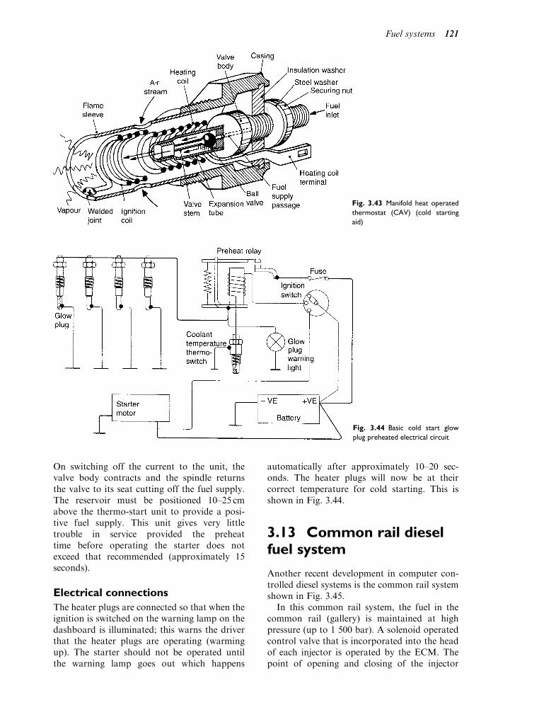
On switching off the current to the unit, thevalve body contracts and the spindle returnsthe valve to its seat cutting off the fuel supply.The reservoir must be positioned 10–25 cmabove the thermo-start unit to provide a posi-tive fuel supply. This unit gives very littletrouble in service provided the preheattime before operating the starter does notexceed that recommended (approximately 15seconds).
Electrical connections
The heater plugs are connected so that when theignition is switched on the warning lamp on thedashboard is illuminated; this warns the driverthat the heater plugs are operating (warmingup). The starter should not be operated untilthe warning lamp goes out which happens
automatically after approximately 10–20 sec-onds. The heater plugs will now be at theircorrect temperature for cold starting. This isshown in Fig. 3.44.
3.13 Common rail dieselfuel system
Another recent development in computer con-trolled diesel systems is the common rail systemshown in Fig. 3.45.
In this common rail system, the fuel in thecommon rail (gallery) is maintained at highpressure (up to 1 500 bar). A solenoid operatedcontrol valve that is incorporated into the headof each injector is operated by the ECM. Thepoint of opening and closing of the injector
Fig. 3.43 Manifold heat operated
thermostat (CAV) (cold starting
aid)
Fig. 3.44 Basic cold start glow
plug preheated electrical circuit
Fuel systems 121
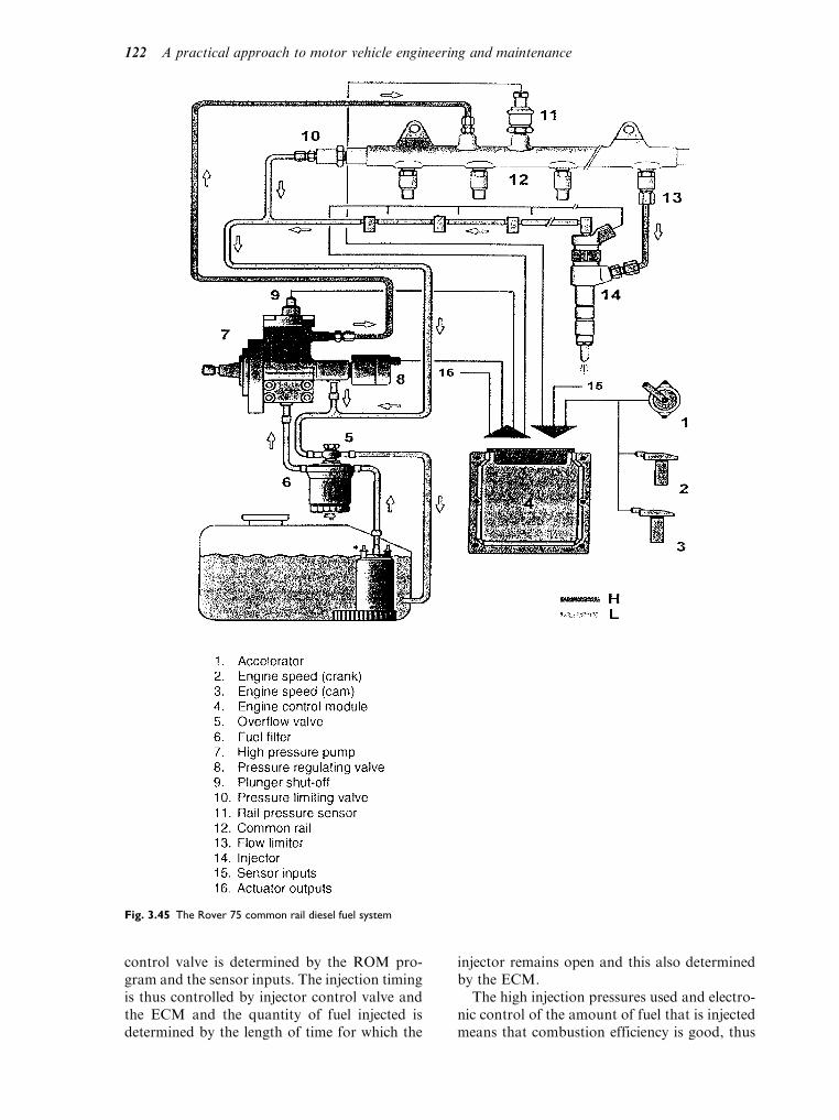
control valve is determined by the ROM pro-gram and the sensor inputs. The injection timingis thus controlled by injector control valve andthe ECM and the quantity of fuel injected isdetermined by the length of time for which the
injector remains open and this also determinedby the ECM.
The high injection pressures used and electro-nic control of the amount of fuel that is injectedmeans that combustion efficiency is good, thus
Fig. 3.45 The Rover 75 common rail diesel fuel system
122 A practical approach to motor vehicle engineering and maintenance

leading to improved fuel economy and reducedemissions.
Common rail diesel systeminjectors
Figure 3.46 shows two views of an electronicallycontrolled injector that is used in typical Com-mon Rail diesel fuel system. In diagram A, thecontrol valve is closed and no fuel is beinginjected while, in diagram B the control valveis open and fuel is being injected into the enginecylinder.
Operation of injector in the closedposition (diagram A)
The solenoid (1) is not energised and the con-trol valve (2) is held on its seat. Fuel from thecommon rail fills the upper chamber (4) andthe lower chamber (7). The pressures in theupper and lower chambers are equal. Theinjector needle valve (8) is held firmly on itsseat by control spring (6) and no injectionoccurs.
Operation of the injector in the openposition (diagram B)
An electrical pulse from the ECM energises thesolenoid (1), lifting the control valve (2) andreleasing pressure in the upper chamber (4).The imbalance of pressure between the upperand lower chambers causes the injector needlevalve (8) to be lifted against the spring (6)and atomised fuel is injected into the enginecylinder.
Learning tasks
1. Remove a DPA fuel injection pump from a
diesel engine. Turn both the pump and
engine, time the pump to the engine, bleed
the fuel system and run the engine.
2. Draw up a service schedule for a diesel
system fitted with a DPA fuel pump. Base
the schedule on either mileage or time.
3. State how the timing of a DPA fuel injection
pump is adjusted. When would it be neces-
sary to carry out this adjustment?
4. Remove the heater plugs, clean and check
their resistance. Record your results and
compare them with the manufacturer’s
recommendations. How would the driver
notice if the heater plugs were not operating
correctly?
5. Write out a logical test procedure for iden-
tifying the fault of a diesel engine producing
black smoke when operating under load.
6. Complete the above test and produce a
report to show the minimum and maximum
engine revs, static timing, amount of advance
on acceleration and amount of smoke allow-
able from the exhaust for a diesel engine.
Compare your results with the manufac-
turer’s data and produce a set of recom-
mendations for the customer’s report
sheet. Name any specialized equipment used
together with printouts that were produced
in the test.
7. Remove a set of injectors from both direct
injection and indirect injection engines.
Using the correct equipment, test for cor-
rect opening pressure, back leakage and
spray pattern. Refit the injectors and run
the engine.
8. Dismantle both types of injectors and iden-
tify the main differences. After cleaning all
the components reassemble the injectors,
set the pressure and check back leakage
and spray pattern.
1 2
3
4
5
6
7 8
Fuel
ElectInput
A B
Coil
Valve (upper chamber)
Spring (upper chamber)
Upper chamber
Spring (lower chamber)
Lower chamber
Push rod
Fuel needle
1
2
3
4
5
6
7
8
Fig. 3.46 A common rail fuel injector
Fuel systems 123

9. On undertaking a smoke meter test on a
diesel engine, it was found that the smoke
produced was excessive. Draw up a simple
logical test procedure for tracing and recti-
fying the fault.
Practical assignment – SUcarburettor
Activity – tuning singlecarburettors
1. (a) Warm engine up to normal temperature.
(b) Switch off engine.
(c) Unscrew the throttle adjusting screw until
it is just clear of its stop and the throttle is
closed.
(d) Set throttle adjusting screw 1 12
turns open.
2. (a) Mark for reassembly and remove piston/
suction chamber unit.
(b) Disconnect mixture control wire.
(c) Screw the jet adjusting nut until the jet is
flush with the bridge of the carburettor or
fully up if this position cannot be obtained.
3. (a) Replace the piston/suction chamber unit as
marked.
(b) Check that the piston falls freely onto the
bridge when the lifting pin (6) is released.
(c) Turn down the jet adjusting nut (I) two
complete turns.
4. (a) Restart the engine and adjust the throttle
adjusting screw (5) to give desired idling as
124 A practical approach to motor vehicle engineering and maintenance
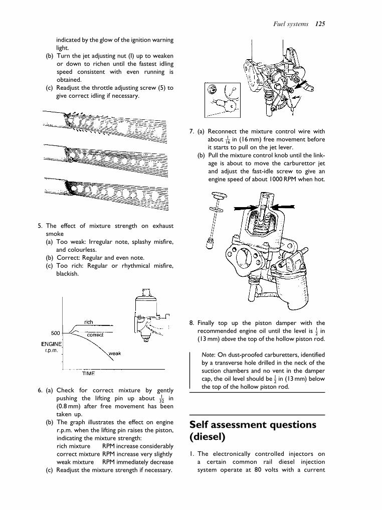
indicated by the glow of the ignition warning
light.
(b) Turn the jet adjusting nut (I) up to weaken
or down to richen until the fastest idling
speed consistent with even running is
obtained.
(c) Readjust the throttle adjusting screw (5) to
give correct idling if necessary.
5. The effect of mixture strength on exhaust
smoke
(a) Too weak: Irregular note, splashy misfire,
and colourless.
(b) Correct: Regular and even note.
(c) Too rich: Regular or rhythmical misfire,
blackish.
6. (a) Check for correct mixture by gently
pushing the lifting pin up about 132
in
(0.8 mm) after free movement has been
taken up.
(b) The graph illustrates the effect on engine
r.p.m. when the lifting pin raises the piston,
indicating the mixture strength:
rich mixture RPM increase considerably
correct mixture RPM increase very slightly
weak mixture RPM immediately decrease
(c) Readjust the mixture strength if necessary.
7. (a) Reconnect the mixture control wire with
about 116
in (16 mm) free movement before
it starts to pull on the jet lever.
(b) Pull the mixture control knob until the link-
age is about to move the carburettor jet
and adjust the fast-idle screw to give an
engine speed of about 1000 RPM when hot.
8. Finally top up the piston damper with the
recommended engine oil until the level is 12
in
(13 mm) above the top of the hollow piston rod.
Note: On dust-proofed carburetters, identified
by a transverse hole drilled in the neck of the
suction chambers and no vent in the damper
cap, the oil level should be 12
in (13 mm) below
the top of the hollow piston rod.
Self assessment questions(diesel)
1. The electronically controlled injectors on
a certain common rail diesel injection
system operate at 80 volts with a current
Fuel systems 125

of 20 amperes. The power of these inject-
ors is:
(a) 16 kW
(b) 1 600 Watts
(c) 4 Watts
(d) 0.25 kW
2. In indirect injection diesel engines:
(a) the injectors spray fuel into the induction
manifold
(b) the injectors spray fuel into a pre-combus-
tion chamber
(c) the fuel is injected into a cavity in the piston
crown
(d) the injection pressure is 10 bar
3. Diesel injectors are lubricated:
(a) by a separate supply of engine oil
(b) by means of a grease nipple mounted on the
injector nozzle
(c) by leak back of diesel fuel
(d) by coating the needle valve with PTFE
4. In a diesel fuel system equipped with an in-line
injection pump, dribble from the injectors is
prevented by:
(a) a strong injector spring
(b) reducing the pressure at the lift pump
(c) a cylindrical collar on the delivery valve
(d) a sharp cut-off profile on the injection pump
camshaft
5. Checking the phasing of an in-line fuel injection
pump is carried out to:
(a) ensure that fuel injection starts at the
correct number of degrees after top dead
centre
(b) ensure that each element commences
delivery at the correct angular interval
(c) ensure that the engine cannot run back-
wards
(d) ensure that the lift pump is working
6. The low pressure, diaphragm type lift pump
operates at:
(a) 345 bar
(b) 34:5 kN=m2
(c) 104 kN=m2
(d) 0.104 bar
7. Spill timing is a process that:
(a) permits the operator to determine the
point at which an element of the injector
pump starts to inject so that the pump can
be timed to the engine
(b) determines the amount of time that fuel
flows through the spill port
(c) sets the amount of fuel that each pump
element delivers
(d) sets the time constant of an electronic
control unit
8. After fitting a new fuel filter element, the fuel
system should be:
(a) completely drained down
(b) bled to remove any air that may be trapped
(c) bled by slackening the connections at the
injectors
(d) put back into commission by starting the
engine
9. The excess fuel device on an injection pump:
(a) is used to increase pulling power on steep
hills
(b) comes into operation when the turbo-
charger is operating
(c) is a cold start aid
(d) increases the engines thermal efficiency
10. Diesel fuel injectors operate at:
(a) approximately 180 bar
(b) 7:5 lbf=in2
(c) 0.05 Mpa
(d) 18 kN=m2
Self assessment questions(petrol fuel systems)
1. In the mixture control idling system of a car-
burettor, the CO content of the exhaust gas at
idling speed can be adjusted. Which one of the
following is accurate?
(a) turning the idle mixture adjustment screw
clockwise weakens the mixture
(b) turning the idle mixture adjustment anti-
clockwise weakens the mixture
(c) to make this adjustment the engine must be
cold
(d) the choke must be operating
2. When performing a test to check fuel gallery
pressure on a petrol injection system a pressure
test gauge may be temporarily connected into the
petrol supply line. In order to perform this test:
(a) the fuel system must be de-pressurised
before connecting the pressure test gauge
(b) the gallery pressure should not exceed 1 bar
(c) the gallery pressure should be several hun-
dred bar
(d) the manifold absolute pressure sensor
should be disconnected
3. In an EOBD system, the exhaust oxygen sensor
that is placed downstream from the catalytic
convertor is used to:
(a) act as a back in case the upstream oxygen
sensor fails
126 A practical approach to motor vehicle engineering and maintenance
(b) monitor the catalyst performance
(c) control emissions while the engine is cold
(d) operate the exhaust gas re-circulation valve
4. In an EOBD type engine management system,
the engine idle speed is controlled by:
(a) the electronic idle valve, or stepper motor
that is under the control of the engine con-
trol module
(b) the exhaust gas re-circulation valve
(c) the electronic idle valve and ignition timing
in response to outputs from the engine
control module
(d) the engine temperature sensor
5. Exhaust gas re-circulation helps to control
emissions by:
(a) heating up the catalyst when the engine is cold
(b) reducing fuel consumption
(c) reducing temperatures in the combustion
chamber so that the production of NOx is
reduced
(d) increasing the volumetric efficiency
6. The test data for the supply voltage at a mani-
fold absolute pressure sensor, states that the
voltage should be 5 volts, plus or minus 4%.
During a test of such a sensor, the voltage read-
ing should be:
(a) 5.4 volts
(b) 4.6 volts
(c) between 4.8 volts and 5.2 volts
(d) 5 100=4 volts
7. The carbon canister in the fuel system reduces
emissions because:
(a) the evaporative purge control valve permits
fuel vapour from the petrol tank to be
passed from the carbon canister to the
engine for consumption
(b) the carbon enriches the fuel
(c) the carbon absorbs petrol vapour so that
the carbon canister can be emptied period-
ically
(d) the carbon canister lowers fuel pressure in
the gallery
8. In a throttle body petrol injection system:
(a) there is a separate injector for each cylinder
(b) there is a single injector at the throttle
body
(c) air flow is not metered
(d) a catalytic convertor is not required for
control of emissions
9. In a petrol engine, the air–fuel ratio for chem-
ically correct combustion is:
(a) 28:1
(b) 14.7:1
(c) 21:1
(d) 19.6:1
Fuel systems 127
4Engine air supply and exhaust systems
Topics covered in thischapter
Engine air supply – air filters – manifolds
Exhausts systems – silencers
Oxygen sensor
Air flow meters
Turbo-charger
Liquid fuels such as petrol and diesel oil containthe energy that powers the engine. Hydrogen andcarbon are the main constituents of these fuelsand they need oxygen to make them burn andrelease the energy that they contain. The oxygenthat is used for combustion comes from theatmosphere. Atmospheric air contains approxi-mately 77% nitrogen and 23% oxygen by weight.For proper combustion, vehicle fuels requireapproximately 15kg of air for every 1 kg of fuel.When the fuel and air are mixed and burned inthe engine, chemical changes take place anda mixture of gases is produced. These gases arethe exhaust. The principal exhaust gases arecarbon dioxide, nitrogen and water (steam).
Safety note
You should be aware that combustion is often
not complete and carbon monoxide is produced
in the exhaust. Carbon monoxide is deadly if
inhaled. For this reason, engines should never
be run in confined spaces. Workshops where
engines are operated inside must be equipped
with adequate exhaust extraction equipment.
If all conditions were perfect the fuel and airwould burn to produce carbon dioxide, super-heated steam, and nitrogen (Fig. 4.1). Unfortu-nately these ‘perfect’ conditions are rarelyachieved and significant amounts of otherharmful gases, namely carbon monoxide CO,
hydrocarbons HC, oxides of nitrogen NOx and
solids (particulates like soot and tiny metallicparticles) are produced (Fig. 4.2).
Most countries have laws that control theamounts of the harmful gases (emissions) thatare permitted and engine air and exhaust sys-tems are designed to comply with these laws.
4.1 Engine air supplysystems (carburettor)
Figure 4.3 shows the main features of a petrol(spark ignition) engine air supply system. Ourmain concern, at the moment, is the air cleaner
and the intake pipe (induction tract) leading tothe combustion chamber. The blow-by filter andthe positive crankcase ventilation (PCV) systemare part of the emission control system.
Air filter
The purpose of the air filter (Fig. 4.4) is toremove dust and other particles so that the airreaching the combustion chamber is clean. Pul-sations in the air intake generate quite a lot ofnoise and the air cleaner is designed so that italso acts as an intake silencer.
The porous paper element is commonly usedas the main filtering medium. Intake air isdrawn through the paper and this traps dirt onthe surface. In time this trapped dirt can blockthe filter and the air filter element is replaced atregular service intervals. Failure to keep the airfilter clean can lead to problems of restricted airsupply which, in turn, affects combustion andexhaust emissions.
Temperature control of theengine air supply
To improve engine ‘warm up’ and to provideas near constant air temperature as possible,the air cleaner may be fitted with a device thatheats up the incoming air as and when required.

Figure 4.5 shows the layout of a temperaturecontrolled air intake.
It shows that the manifold vacuum has liftedthe intake control door off its seat and air isdrawn into the air cleaner over the surface ofthe exhaust manifold. The bi-metallic spring haspushed the air bleed valve on to its seat. Whenthe air in the air cleaner reaches a temperatureof 25–30 C, the bi-metal spring lifts the airbleed valve from its seat. This removes thevacuum from above the air control door
diaphragm, thus closing the intake control door.The intake air now enters direct from the atmos-phere. During cold weather the temperature-control system will be in constant operation.
Checking the operation of the aircontrol valve
Figure 4.6 shows the type of practical test thatcan be applied to check the operation of the aircontrol diaphragm and the air door. The flap israised against the spring and a finger is placedover the vacuum pipe connection. The air doorvalve is then released and the valve shouldremain up off its seat.
Fuel injected engine air intakesystem
Figure 4.7 shows an air intake system for amodern engine fitted with electronic controls.
Fig. 4.1 Engine showing fuel/air in and exhaust out
Fig. 4.2 Various bad emissions from engine and fuel system
Fig. 4.3 An engine air supply system
Fig. 4.4 An air cleaner
Engine air supply and exhaust systems 129

This system has several components that weneed to consider briefly.
Air flow meter
The air intake for a fuel injected petrol engineincludes an air flow meter (Fig. 4.8). The purposeof the air flow meter is to generate an electricalsignal that ‘tells’ the electronic controller howmuch air is flowing into the combustion cham-bers. It is also known as an ‘air flow sensor’.
The intake air stream causes a rotating actionon the sensor flap, about its pivot. The angular
movement of the flap produces a voltage at thesensor that is an accurate representation of theamount of air entering the engine. This voltagesignal is conducted to the electronic control unit(ECU), where it is used in ‘working out’ theamount of fuel to be injected.
Throttle position sensor(potentiometer)
This is the sensor (shown as 6 on Fig. 4.7) that‘tells’ the ECU the angular position of the throt-tle butterfly valve. The principle of a throttleposition sensor is shown in Fig. 4.9. The voltagefrom the throttle position sensor is also con-ducted to the ECU for use in the process ofdetermining the amount of fuel to be injected.
Idle air control
When the driver’s foot is removed from theaccelerator pedal, the throttle butterfly valve isvirtually closed. In order that the engine willcontinue to run properly (idle) the intake systemis provided with a separate system that providesan air supply for idling purposes. Figure 4.10shows an electronically controlled air valve.
Air valves of the type shown in Fig. 4.10 arecontrolled by the ECU. The ECU will admitextra air to provide fast-idle speed so that theengine keeps running even when extra load isimposed with the throttle closed, such as byswitching on the headlights.
Air intake manifold
On many engines the intake air is supplied to acentral point on the intake manifold as shown inFig. 4.11. Themanifold is providedwith ports thatconnect to the individual cylinders of the engine.The seal, often a gasket, between the intake mani-fold and the cylinder head must be secure and it is
Fig. 4.5 Temperature control of intake air
Fig. 4.6 Checking the air control valve
130 A practical approach to motor vehicle engineering and maintenance

Fig. 4.7 Air supply system – petrol injection engine
Fig. 4.8 An air flow meter Fig. 4.9 Throttle position sensor
Engine air supply and exhaust systems 131

advisable to check the tightness of the securingnuts and bolts periodically. These nuts and boltsmust be tightened in the proper sequence, shownfor a particular engine in Fig. 4.12.
Variable length induction tract
The length of the induction tract (tube) throughwhich the engine’s air supply is drawn has an effecton the operating efficiency of the engine. Forlow to medium engine speeds a long inductiontract is beneficial whereas a shorter induction tractis beneficial at high engine speed. Figure 4.13(a)
shows a simplified variable length inductionsystem. An electronically controlled valve betweenthe throttle valve and the engine switches air flowbetween the long and short tracts as requiredby engine speed. At low to medium engine speedthis air valve is closed as shown in Fig. 4.13(b).As the engine speed rises the electronic controlunit causes the air valve to open, as shown inFig. 4.13(c) and the main mass of air enters theengine through by the short route.
Turbo charging
Engines that rely on atmospheric air pressurefor their operation are known as naturally aspir-ated engines. The power output of naturallyaspirated engines is limited by the amount of
Fig. 4.10 An air control valve
Fig. 4.11 An air intake manifold
Fig. 4.12 Tightening sequence for exhaust manifold retaining
hardware (nuts)
132 A practical approach to motor vehicle engineering and maintenance
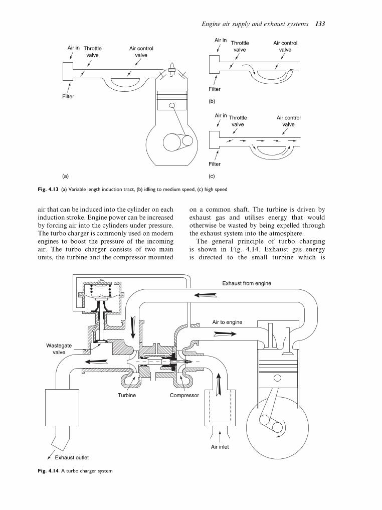
air that can be induced into the cylinder on eachinduction stroke. Engine power can be increasedby forcing air into the cylinders under pressure.The turbo charger is commonly used on modernengines to boost the pressure of the incomingair. The turbo charger consists of two mainunits, the turbine and the compressor mounted
on a common shaft. The turbine is driven byexhaust gas and utilises energy that wouldotherwise be wasted by being expelled throughthe exhaust system into the atmosphere.
The general principle of turbo chargingis shown in Fig. 4.14. Exhaust gas energyis directed to the small turbine which is
(c)
(b)
(a)
Filter
Air in Air controlvalve
Throttlevalve
Air in
Filter
Throttlevalve
Air controlvalve
Air in
Filter
Throttlevalve
Air controlvalve
Fig. 4.13 (a) Variable length induction tract, (b) idling to medium speed, (c) high speed
Wastegatevalve
Turbine Compressor
Exhaust outlet
Air inlet
Air to engine
Exhaust from engine
Fig. 4.14 A turbo charger system
Engine air supply and exhaust systems 133

connected to the shaft that also drives thecompressor. After driving the turbine, theexhaust gas travels through the exhaustsystem and out through the tail pipe. Intakeair is drawn into the compressor throughthe air filter. The compressor raises thepressure to approximately 0.5 bar aboveatmospheric pressure and the pressure iscontrolled by the waste gate valve that allowsthe exhaust gas to by-pass the turbine.
Service attention to the air supplysystem
A normal service requirement is to renew the airfilter element at regular intervals. Should thefilter element become ‘clogged’ it will restrictthe flow of air to the engine and cause the engineto ‘run rich’. This will obviously affect theengine performance and it will also cause theemission control system to malfunction. Toguard against problems in this area, all vehiclesshould be properly serviced before they aretested for compliance with the emissions regula-tions, for example, a pre-MOT service andcheck-over.
Other items that should receive regular atten-tion include: sensor connections, condition offlexible hoses and tightness of joints and securingbrackets. Air flow meters, throttle position sen-sors, etc. are normally quite reliable. In the eventof problems with these items, it will normally benecessary to ‘read out’ fault codes, either throughthe ‘on-board’ diagnostic system or by the use ofdiagnostic code readers and other tools.
4.2 Exhaust system
A fundamental purpose of the exhaust system isto convey exhaust gas away from the engine andto expel it into the surrounding atmosphere atsome point that is convenient to vehicle occu-pants. On motor cars this usually meansthrough the tail pipe at the rear of the vehicle.On trucks it is often at some other point, oftenjust behind the driver’s compartment. Anotherfunction of the exhaust system is to deaden theexhaust sound to an acceptable level. Thissound level is regulated by law.
The exhaust system shown in Fig. 4.15 has anumber of sections. Starting at the front of thevehicle the sections are: the down pipe, or frontpipe; the unit marked 1, this is the catalytic
convertor, an interconnecting pipe to the first
silencer (2); a further length of pipe which iscurved to take it round other units on thevehicle; this pipe connects to the rear silencer
(3); and the gas finally leaves through the tail
pipe.The exhaust system is mounted firmly to the
exhaust manifold at the front end, but it isflexibly mounted to the underside of the vehiclefor the remainder of its length. The flexiblemountings are required to allow the system tomove independently of the main vehicle struc-ture. This allows for the fact that the engineitself is normally flexibly mounted, and the typeof exhaust mountings used prevent noise andvibration being transmitted to the vehicle struc-ture. In order to provide for ease of mainte-nance and economy when replacing parts, the
Fig. 4.15 Underside view of an exhaust system
134 A practical approach to motor vehicle engineering and maintenance

exhaust system is made up from a number ofseparate components. The number of such partsvaries from vehicle to vehicle, but Fig. 4.16shows a typical exhaust system, together withits fixings.
The exhaust catalyst is dealt with at the endof this section. The two silencers may be ofdifferent types, expansion-type and absorption-type. The expansion-type is sometimes calleda resonator because of the way that it works.Figure 4.17 shows the basic principles of the twotypes of silencer commonly used.
Broken or damaged exhaustsystems
In addition to the noise factor, which is oftenthe most evident sign of a broken exhaustsystem, there is also the danger of leakingexhaust gas finding its way into the passengercompartment. Broken exhaust systems shouldbe repaired as a matter of urgency and, whenan exhaust has been repaired, it should be thor-oughly checked to ensure that there are noleaks. In order to prevent leaks, all pipe joints,flanges and their gaskets and other fixings mustbe made secure, using sealant where it is recom-mended.
Catalytic convertor
Function
The purpose of the catalytic convertor is toenable the vehicle to comply with emissions reg-ulations. The principal emissions of concern areoxides of nitrogen (NOx), hydrocarbons (HC),carbon monoxide (CO) plus particulates
Fig. 4.16 Component parts of an exhaust system
Fig. 4.17 Silencers (a) expansion-type, (b) absorption-type
Engine air supply and exhaust systems 135
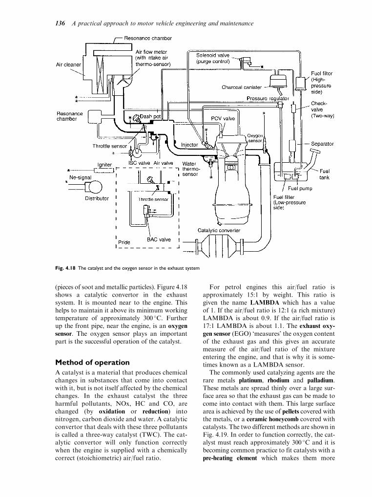
(pieces of soot and metallic particles). Figure 4.18shows a catalytic convertor in the exhaustsystem. It is mounted near to the engine. Thishelps to maintain it above its minimum workingtemperature of approximately 300 C. Furtherup the front pipe, near the engine, is an oxygen
sensor. The oxygen sensor plays an importantpart is the successful operation of the catalyst.
Method of operation
A catalyst is a material that produces chemicalchanges in substances that come into contactwith it, but is not itself affected by the chemicalchanges. In the exhaust catalyst the threeharmful pollutants, NOx, HC and CO, arechanged (by oxidation or reduction) intonitrogen, carbon dioxide and water. A catalyticconvertor that deals with these three pollutantsis called a three-way catalyst (TWC). The cat-alytic convertor will only function correctlywhen the engine is supplied with a chemicallycorrect (stoichiometric) air/fuel ratio.
For petrol engines this air/fuel ratio isapproximately 15:1 by weight. This ratio isgiven the name LAMBDA which has a valueof 1. If the air/fuel ratio is 12:1 (a rich mixture)LAMBDA is about 0.9. If the air/fuel ratio is17:1 LAMBDA is about 1.1. The exhaust oxy-
gen sensor (EGO) ‘measures’ the oxygen contentof the exhaust gas and this gives an accuratemeasure of the air/fuel ratio of the mixtureentering the engine, and that is why it is some-times known as a LAMBDA sensor.
The commonly used catalyzing agents are therare metals platinum, rhodium and palladium.These metals are spread thinly over a large sur-face area so that the exhaust gas can be made tocome into contact with them. This large surfacearea is achieved by the use of pellets covered withthe metals, or a ceramic honeycomb covered withcatalysts. The two different methods are shown inFig. 4.19. In order to function correctly, the cat-alyst must reach approximately 300 C and it isbecoming common practice to fit catalysts with apre-heating element which makes them more
Fig. 4.18 The catalyst and the oxygen sensor in the exhaust system
136 A practical approach to motor vehicle engineering and maintenance

effective during cold starts. A note of warningtoo. Leaded fuel will ‘poison’ a catalyst and pre-vent it from working. Leaded fuel must never beused in an engine fitted with a catalytic convertor.
Oxygen sensor
The exhaust oxygen sensor is a critical part of theengine emissions control system. The oxygen sen-sor transmits an electrical signal to the ECU andthe ECU then makes the necessary adjustmentsto the amount of fuel injected so that LAMBDAis maintained within the design limits. The activeelement (a ceramic) of the oxygen sensor is sensi-tive to temperature and it must be hot for it towork properly. For this reason, oxygen sensorsare often fitted with an electric heating element.This type of sensor is then known as a heated
exhaust gas oxygen sensor (HEGO).At the time of writing, there are two different
types of exhaust oxygen sensors in common use.One type uses zirconium oxide; this produces asmall voltage at its terminals. The other typeuses titanium oxide; this relies on changes ofconductivity for its operation and is suppliedwith voltage. It is important to recognize this
because the test procedures for the sensorsinvolve different procedures. Exhaust oxygensensors are shown in Fig. 4.20.
Exhaust emissions test
Exhaust emissions are tested by means of anexhaust gas analyser. Failure to ‘pass’ the testdoes not necessarily mean that the catalyst hasfailed. As mentioned in the section on air sup-ply, a choked air filter can upset the wholesystem. Exhaust catalysts are expensive itemsand it is important to make sure that all otherparts of the engine emissions system are in goodworking order before condemning the catalyst.
Maintenance
Exhaust systems are subject to corrosive attackfrom the outside and the inside environment. Theoutside corrosion arises from water, salt andother corrosive substances that may be presenton the running surface. The internal corrosionarises, in part, from the water that is producedby combustion of the fuel. Each litre of petrolburned produces almost a litre of water. Whenthe exhaust system is hot, the water leaves the tailpipe as super-heated steam but, when the exhaustsystem is cold and the atmospheric conditions areright, some of the steam condenses to waterinside the exhaust. To extend the life of exhaustsilencers they are sometimes coated, internallyand externally, with a thin layer of aluminium.The exterior of the whole exhaust system shouldbe checked for signs of holes and all pipe clampsand joints should checked for leaks. The flexiblemountings should also be checked from time totime and any that are found to be in danger ofbreaking should be replaced, in order to preventmore expensive work at some later date.
Learning tasks
1. Draw up a list of the equipment that you
have used to perform an emissions test for
an MOT. Describe the procedure and give
details of the acceptable MOT emissions
levels for any modern vehicle.
2. Draw up a test procedure for checking the
oxygen sensor. Itemize any precautions that
should be observed, e.g. corrosion of ter-
minals and care when removing and refitting.
3. Remove a complete exhaust system from a
vehicle, including the exhaust manifold.
Replace the manifold gasket and any
Fig. 4.19 Exhaust catalysts. (a) Pellet-type catalytic converter.
Catalysts supported on aluminas, carbons and other speciality
materials are produced for use in many chemical processes. The
cost-effectiveness and catalytic selectivity of finely dispersed
platinum group metal catalysts greatly exceeds those of alter-
native processes: indeed, many modern processes depend
exclusively on these catalysts, (b) Honeycomb- or monolithic-
type catalytic converter. Autocatalysts utilize honeycomb sup-
ports to assure the maximum reactive surface within the smal-
lest possible volume, with consequent high catalytic activity and
minimum engine power loss. Whilst the majority of catalysts
use a ceramic support, some specialized applications demand
the added durability of steel supports
Engine air supply and exhaust systems 137
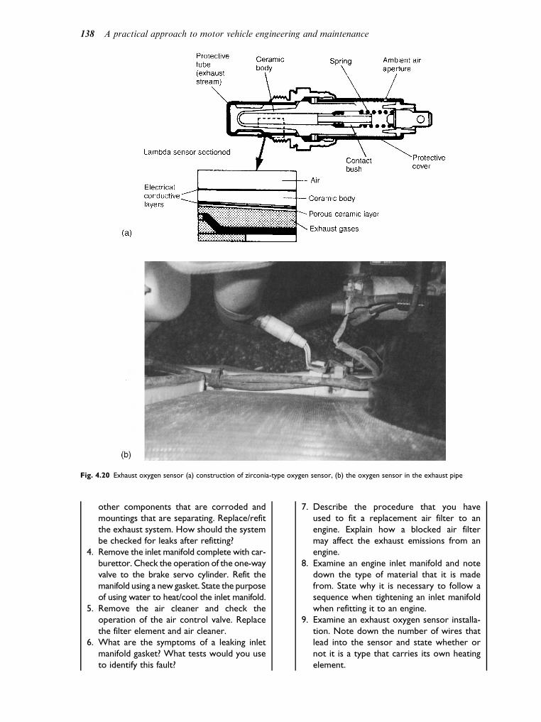
other components that are corroded and
mountings that are separating. Replace/refit
the exhaust system. How should the system
be checked for leaks after refitting?
4. Remove the inlet manifold complete with car-
burettor. Check the operation of the one-way
valve to the brake servo cylinder. Refit the
manifold using a new gasket. State the purpose
of using water to heat/cool the inlet manifold.
5. Remove the air cleaner and check the
operation of the air control valve. Replace
the filter element and air cleaner.
6. What are the symptoms of a leaking inlet
manifold gasket? What tests would you use
to identify this fault?
7. Describe the procedure that you have
used to fit a replacement air filter to an
engine. Explain how a blocked air filter
may affect the exhaust emissions from an
engine.
8. Examine an engine inlet manifold and note
down the type of material that it is made
from. State why it is necessary to follow a
sequence when tightening an inlet manifold
when refitting it to an engine.
9. Examine an exhaust oxygen sensor installa-
tion. Note down the number of wires that
lead into the sensor and state whether or
not it is a type that carries its own heating
element.
Fig. 4.20 Exhaust oxygen sensor (a) construction of zirconia-type oxygen sensor, (b) the oxygen sensor in the exhaust pipe
138 A practical approach to motor vehicle engineering and maintenance

10. After fitting a new exhaust system it is
necessary to check that there are no leaks
in the system. Describe the practical meth-
ods that you use, in your workplace, to
carry out this check.
11. Exhaust fumes are very dangerous. Write
down the precautions that must be observed
when working on running engines, in a con-
fined space. Make a list of the exhaust extrac-
tion equipment fitted in your workshop.
Practical assignment – airsupply and exhaust systems
Objective
The purpose of this assignment is to allow you to
develop your knowledge and skill in this important
area of motor vehicle work and to help you to
build up your file of evidence for NVQ.
Activity
The nature of this assignment is such that you will
need to work under supervision, unless you have
previously been trained and are proficient. The
assignment is intended to be undertaken during a
routine service and MOT test on a petrol engined
vehicle that is equipped with electronically con-
trolled petrol injection.
The assignment is in two parts.
Part 1
1. Locate the idle control valve. Describe the pur-
pose of this valve and describe any adjustments
that can be made to it.
2. Specify the effects on engine performance and
exhaust emissions that may arise if this valve is
not working correctly.
Part 2
1. Perform the emissions test part of the MOT test.
2. Record the results and compare them with the
legal limits.
3. Write short notes on the test procedure and
describe any work that should be carried out
before starting the emissions test.
4. Give details of remedial work that can be per-
formed if a vehicle should fail the emissions test.
5. Make a list of the tools and equipment used.
Self assessment questions
1. A blocked air filter may cause:
(a) low fuel consumption
(b) the engine to run rich
(c) increased cooling system pressure
(d) excess oxygen in the exhaust
2. An air leak through the intake manifold flange
gasket may cause:
(a) the engine to run rich
(b) the mal-function indicator lamp to illuminate
(c) the positive crankcase ventilation system to
fail
(d) excess Nox in the exhaust
3. Turbocharged engines:
(a) are less efficient than naturally aspirated
ones because power is absorbed in driving
the turbo charger
(b) are more efficient than naturally aspirated
engine because the make use of energy in
the exhaust gas that would otherwise be
wasted
(c) are normally diesel engines
(d) have high fuel consumption
4. An air flow sensor:
(a) provides an electrical signal that tells the
ECU how much air is flowing to the engine
(b) controls the air flow to the air conditioning
system
(c) allows the exhaust gases to by-pass the
turbo charger
(d) restricts air flow to prevent engine over-
load
5. The potentiometer type throttle position sensor:
(a) generates electricity that is used as a signal
to inform the ECU of the amount of throt-
tle opening
(b) receives a supply of electricity and sends a
signal to the ECU that is an accurate repre-
sentation of throttle position
(c) is always situated on the accelerator pedal
(d) always operates on the variable capacitance
principle
6. Exhaust gas oxygen sensors:
(a) are used to detect oxygen levels in the
exhaust gas
(b) operate affectively at all temperatures
(c) always generate electricity
(d) are only needed on direct injection engines
7. During combustion, hydrogen in the fuel com-
bines with oxygen from the air:
(a) and produces water in the exhaust system
(b) and produces Nox in the exhaust gas
Engine air supply and exhaust systems 139

(c) and produces carbon monoxide in the
exhaust gas
(d) and causes the ignition to be retarded
8. When an engine fails the emissions test it means
that:
(a) the catalytic convertor is not working
(b) the emissions control system is not work-
ing and this may be caused by a range of
engine problems
(c) the oxygen sensor has failed
(d) the air filter is blocked
9. Exhaust systems may be protected against
corrosion by:
(a) coating them inside and outside with a layer
of bitumen
(b) a thin layer of aluminium applied to the
inner and outer surfaces
(c) reducing the temperature of the exhaust
gases
(d) coating them with underseal
10. Atmospheric air contains approximately 77%
nitrogen and 23% oxygen by mass:
(a) the nitrogen is a hindrance because it is
not used in combustion
(b) the nitrogen helps to form water
(c) the nitrogen forms part of the gas that
expands in the cylinder to make the engine
work
(d) the oxygen and nitrogen makes Nox at
very low temperatures
140 A practical approach to motor vehicle engineering and maintenance

5Transmission systems
Topics covered in thischapter
Clutch
Gearbox
Fluid flywheel and torque convertor
Transmission systems – drive shafts
Hub types – semi-floating, fully floating,
three-quarter floating
Gear ratios – torque multiplication
5.1 The clutch
Most clutches used in the modern motor car arecalled friction clutches. This means that theyrely on the friction created between two surfacesto transmit the drive from the engine to thegearbox. The clutch fulfils a number of differenttasks. The three main ones are:
. it connects/disconnects the drive between theengine and the gearbox;
. it enables the drive to be taken up graduallyand smoothly;
. it provides the vehicle with a temporary neutral.
The three main component parts of a clutch are:
. the driven plate, sometimes referred to as theclutch, centre or friction plate;
. the pressure plate which comes complete withthe clutch cover, springs or diaphragm toprovide the force to press the surfacestogether;
. the release bearing which provides the bearingsurface which, when the driver operates theclutch pedal, disconnects the drive betweenthe engine and the gearbox.
Through the centre of the pressure plate theinput shaft of the gearbox (sometimes calledthe spigot, first motion or clutch shaft) issplined to the middle of the driven plate. On
the conventional vehicle layout it is located ona bearing (called the spigot bearing) in theflywheel.
Multi-spring clutch
The driving members of the multi-spring clutchconsist of a flywheel and pressure plate (bothmade of cast iron) with the driven plate trappedbetween. The pressure plate rotates with theflywheel, by means of projections on it locatingwith slots in the clutch cover which is bolted tothe flywheel. A series of springs located betweenthe cover and the pressure plate force the platetowards the flywheel trapping the clutch platebetween the two driving surfaces. The primary
(or input) shaft of the gearbox is splined to thehub of the clutch disc and transmits the drive(called torque which means turning force) to thegearbox. The drive is disconnected by with-drawing the pressure plate and this is achievedby the operation of the release levers. Figure 5.1shows a multi-spring clutch.
Diaphragm-spring clutch
The diaphragm-spring clutch (shown inFig. 5.2) is similar in many ways to the coilspring type. The spring pressure is provided bythe diaphragm which also acts as the lever tomove the pressure plate. On depressing theclutch pedal the release lever is forced towardsthe flywheel thus pulling the pressure plate awayfrom the flywheel. This type has a number ofadvantages over the coil spring type.
. It is much simpler and lighter in constructionwith fewer parts.
. It has a lighter hold-down pressure and istherefore easier to operate thus reducing dri-ver fatigue.
. The clutch assembly is smaller and more com-pact.
. It provides almost constant pressure through-out the life of the driven plate.

. Unlike the coil spring the diaphragm springis not affected by centrifugal force at highengine speeds. It is also easier to balance.One type of diaphragm spring, the strapdrive, gives almost frictionless movement ofthe pressure plate inside the clutch cover.
Friction plate construction
The important features incorporated in thedesign of a driven plate can best be seen byconsidering the disadvantages of using a planesteel plate with a lining riveted to each side. Anumber of serious problems would very soon beencountered.
. Buckling of the plate can occur due to the heatthat is generated when the drive is taken up.
. The drive may not be disconnected com-pletely (called clutch drag), caused by theplate rubbing against the flywheel when theclutch should be disconnected.
. Very small movement of the clutch pedal. Theclutch is of the ‘in or out’ type, with very little
control over these two points. This may cause asudden take upof the drive (called clutch judder).
To overcome these problems the plate is nor-mally slotted or ‘set’ in such a way as to producea flexing action. Whilst disengaging, the drivenplate will tend to jump away from the flywheeland pressure plate to give a clean break. Whilstin this position the linings will be held apart andair will flow between them to take away theheat. During engagement, spring pressure isspread over a greater range of pedal movementas the linings are squeezed together. This giveseasier control and smoother engagement. Inmost cases the hub is mounted independentlyin the centre of the clutch plate, allowing it totwist independently from the plate. To transmitthe drive to the plate either springs or rubber,bonded to the hub and plate, are used. Thisflexible drive absorbs the torsional (twisting)shocks due to the engine vibrations on clutchtake-up, which could otherwise cause transmis-sion noise or rattle. These features can be seen inthe clutch drive (H) in Fig. 5.2.
Fig. 5.1 The coil spring clutch
142 A practical approach to motor vehicle engineering and maintenance
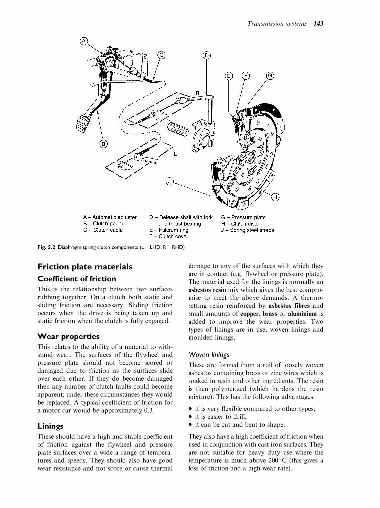
Friction plate materials
Coefficient of friction
This is the relationship between two surfacesrubbing together. On a clutch both static andsliding friction are necessary. Sliding frictionoccurs when the drive is being taken up andstatic friction when the clutch is fully engaged.
Wear properties
This relates to the ability of a material to with-stand wear. The surfaces of the flywheel andpressure plate should not become scored ordamaged due to friction as the surfaces slideover each other. If they do become damagedthen any number of clutch faults could becomeapparent; under these circumstances they wouldbe replaced. A typical coefficient of friction fora motor car would be approximately 0.3.
Linings
These should have a high and stable coefficientof friction against the flywheel and pressureplate surfaces over a wide a range of tempera-tures and speeds. They should also have goodwear resistance and not score or cause thermal
damage to any of the surfaces with which theyare in contact (e.g. flywheel or pressure plate).The material used for the linings is normally anasbestos resin mix which gives the best compro-mise to meet the above demands. A thermo-setting resin reinforced by asbestos fibres andsmall amounts of copper, brass or aluminium isadded to improve the wear properties. Twotypes of linings are in use, woven linings andmoulded linings.
Woven linings
These are formed from a roll of loosely wovenasbestos containing brass or zinc wires which issoaked in resin and other ingredients. The resinis then polymerized (which hardens the resinmixture). This has the following advantages:
. it is very flexible compared to other types;
. it is easier to drill;
. it can be cut and bent to shape.
They also have a high coefficient of friction whenused in conjunction with cast iron surfaces. Theyare not suitable for heavy duty use where thetemperature is much above 200 C (this gives aloss of friction and a high wear rate).
Fig. 5.2 Diaphragm spring clutch components (L¼ LHD, R¼RHD)
Transmission systems 143

Moulded linings
These are more popular now. In this type thevarious components are mixed together andcured in dies at high temperatures and pressuresto form a very hard material. These can with-stand high temperatures and pressures when inuse. Different types of linings can be made havingwidely different coefficients of friction and wearproperties because of the much wider range ofpolymers that can be used in their manufacture.They require more careful handling during dril-ling and riveting as the material is more brittlethan the woven type. They must also be formedto the required radius as they cannot be cut orbent. Heavy duty clutches often use ceramic
materials as these can withstand higher operatingtemperatures and pressures. Since the end ofNovember 1999, asbestos has been banned bylaw in the manufacture of new clutch linings.(Refer to section on Health and Safety.)
Operating mechanisms
The clutch release bearing is fitted to the clutchrelease fork. When the clutch pedal is presseddown by the driver, pressure is exerted againstthe diaphragm spring fingers by the release
bearing forcing them towards the flywheel, thisaction disengages the drive from the engine.
The pedal linkage may be eithermechanical orhydraulic. It must be flexibly mounted as theengine (which is mounted on rubbers) maymove independently of the body/chassis.
Hydraulic linkage
In this arrangement, shown in Fig. 5.3, oil is dis-placed by themovement of the piston in themaster
cylinder to the slave cylinder to operate the releasefork. The reservoir on the master cylinder tops upthe system as wear in the clutch takes place.
Mechanical linkage
This operates on the principle of levers and rodsor cable. The movement ratio and force ratiocan be arranged to give a large force acting onthe clutch with a small force acting on the pedal.Figures 5.2 and 5.4 shows this system.
Adjustment
Adjustment of the hydraulic operating mechan-ism is automatic. As wear of the linings takesplace the piston in the slave cylinder takes upthat amount of wear.
Fig. 5.3 The hydraulic clutch release mechanism. (a) Position of spring with pedal depressed, (b) position of spring in the off (rest)
position
144 A practical approach to motor vehicle engineering and maintenance

The mechanical system is usually a flexiblecable and may have an automatic self-adjustingmechanism as in Fig. 5.2 or else it may needto be checked and adjusted at regular serviceintervals.
Clutch faults
These are the most common faults found on theclutch.
Clutch slip
This occurs when the clutch fails to transmit thepower delivered by the engine. It may be causedby one of the following faults:
. insufficient ‘free’ movement on the clutchpedal or at the withdrawal (release) lever;
. oil or grease on the friction linings;
. friction linings worn out;
. scored faces on the flywheel or pressureplate.
Clutch drag
This produces some difficulty in engaging andchanging gear. It may be cause by one of thefollowing faults:
. insufficiently effective pedal travel (excessive‘free’ movement on the pedal or slave cylinderpush rod);
. hydraulic system defective (due usually to theloss of most if not all of the hydraulic oil);
. release lever broken, incorrectly adjusted orseized;
. release bearing defective;
. clutch plate seized on the gearbox input shaftsplines;
. clutch shaft spigot bearing (used where thegearbox input shaft is located in the flywheel)is seized in the flywheel;
. clutch linings are cracked or buckled;
. oil or grease on the linings.
Vibration or judder
This occurs when the drive is gradually takenup. It can be caused by one of the followingfaults:
. cracked or distorted pressure plate;
. loose or badly worn linings;
. loose or protruding rivets;
. misalignment of the gearbox with the engine,caused by distortion of the bell housing or thedowels not being located correctly;
. engine or gearbox mountings defective;
. excessive backlash (play) in the universaljoints (UJs) of the drive/prop shafts, (boltsmay be loose on the UJ flange);
. flywheel bolts loose on the crankshaft flange;
. defective release mechanism.
Other types of clutches
Multi-plate clutches
Used in certain specialized applications, e.g.agricultural tractors, where a continuous driveis required at the power take-off (PTO); heavy-duty vehicles such as those used by the armedforces; and earth moving and large plant ve-hicles. The most common application that themotor mechanic is likely to see is that of themotor bike where a small multi-plate clutch cantransmit a large amount of power due to thelarge surface area of all the clutch plates addedtogether.
Fluid clutches
The fluid flywheel
The fluid flywheel is a form of automaticclutch. It consists of two main parts, the pump-ing element that is attached to the enginecrankshaft and the turbine element that isattached to the gearbox input shaft. Both partsare encased in a container that carries the oil
Fig. 5.4 Cable-operated clutch arrangement
Transmission systems 145

that allows the unit to function. Both thepumping element and the turbine element con-tain a number of segments as shown inFig. 5.5(a). As the engine crankshaft rotates,oil is directed towards the outer edges of thepumping elements and from there into theouter edges of the turbine element, as shownin Fig. 5.5(b). As the engine speed increases,the force exerted by the oil issuing from thepumping element causes the turbine elementto rotate thus transmitting the drive from theengine to the gearbox, as shown in Fig. 5.5(c).
The fluid flywheel permits the drive to betaken up smoothly as engine speed is graduallyincreased. As the speed of the turbine elementbegins to reach the speed of the pumping ele-ment, the oil returning from the turbine beginsto match the speed of the oil leaving the pump-ing element. This causes a small amount of slipto occur, which is a feature of fluid couplingsand vehicle design allows for this. Fluid
flywheels do not multiply torque, merely actingas automatic clutches.
The torque convertor
The torque convertor is also a form of auto-matic clutch with a third element, known asthe stator, being added. The stator is mountedon an extension of the gearbox casing and actsto re-direct oil flow from the pumping elementto the turbine and, in doing so, increases theengine torque being transmitted from the crank-shaft to the gearbox. The stator is also mountedon a one way clutch, similar in operation to abicycle free-wheel, allowing the stator to rotatewith the other two elements of the torque con-vertor, as the speed of the turbine elementbegins to reach the same speed as the pumpingelement. When all three elements of the conver-tor are rotating together, the unit acts as a fluidflywheel and there is no torque multiplication.When the torque conversion effect is fully
(a)
Pumping elementattached to engineflywheelSegment
Turbine elementattached to gearbox
input shaft
(b)
Oil movesunder influenceof centrifugalforce
Gearbox inputshaftremainsstationaryuntil enginespeed ishigh enoughto move it
Driven roundby engine
Pumpingelement
(c)
Pumping element
Engine speed nowhigh enough tocause turbineto rotate andtransmit driveto gearbox
Fig. 5.5 A fluid flywheel
146 A practical approach to motor vehicle engineering and maintenance

operational, the torque multiplication isapproximately 2:1.
Stalling speed
The stalling speed of a torque convertor is themaximum speed that the engine can reach whenthe transmission is engaged and the vehicle isprevented from moving. At stalling speed, theenergy from the engine is absorbed in a shearingaction of the oil which, in the process, becomesheated. A stalling speed test is one of the teststhat can be performed to check the workingcondition of an automatic transmission system.
Learning tasks
1. By reference to manuals and technology
books, draw up a typical load/deflection
graph for coil and diaphragm spring clutches.
From the graphs state the load for both new
and worn linings in the engaged and disen-
gaged positions. From your results can you
identify a reason why the diaphragm spring
is now the most common type of clutch
used in light vehicles?
2. Remove a clutch from an engine and inspect
the main components. Note the amount of
wear on the following units:
(a) the flywheel
(b) the pressure plate
(c) the release bearing
(d) the driven plate, including the linings
(e) the operating mechanism.
Draw up your recommendations giving
reasons for your findings.
3. What are the service recommendations
for the clutch? Produce a simple service
schedule that would enable your recom-
mendations to be recorded.
4. Describe the symptom (how would the
driver notice) and the cause (what caused
the problem to occur) of the following:
(a) clutch slip
(b) clutch drag
(c) clutch judder
5.2 The gearbox
The purpose of the gearbox is:
. to multiply the torque being transmitted bythe engine;
. to provide a means of reversing the vehicle;
. to provide a permanent position for neutral.
The gearbox can be described as a collectionof levers (the gears) that are arranged so as tomultiply the turning effort (the torque) of theengine to suit the needs of the vehicle.
Transmission layouts
The position of the engine in relation to the rest ofthe transmission is shown in Fig. 5.7. The advan-tages of each layout are taken into considerationby the manufacturer when designing the vehicle.
Types of gears used in thegearbox
Several types of gear teeth shape are used in themodern gearbox depending on the application.All are called spur teeth.
Straight cut teeth
Shown in Fig. 5.8 these have a rolling/slidingaction as they mesh together. They are rathernoisy when running together and generate highforces and temperatures between the gear teethwhich tends to force them apart when highloads are transmitted. They are almost alwaysused for reverse gear. They can also be found inthe gearboxes of some racing cars.
Helical cut teeth
These have the teeth cut at an angle across thegear producing a sideways force which is nor-mally taken by thrust washers on the shaft. The
Pumping element
Stator
To gearbox
Part ofgearboxcasing
Freewheel
Turbineelement
Fromengine
crankshaft
Fig. 5.6 Torque convertor
Transmission systems 147

helical shape is used on the forward gears asthey are quieter running, have more than onetooth in mesh at any one time and can thereforecarry a greater load. Double helical gears aresometimes used to overcome the side force andcan transmit even greater loads but they aremore expensive to produce.
Sliding mesh gearbox
In this type of gearbox, shown in Fig. 5.9, themainshaft gearwheels slide on splines in the direc-tion of the arrows to mesh with the appropriatelayshaft gear for first, second and third gears.Top gear is a dog clutch connection joining inputand output shafts to give a 1:1 ratio. For reversethe ‘compound’ idler gear slides along the shaft tomesh with mainshaft and layshaft first
Fig. 5.7 Transmission arrangements showing the position of the engine, gearbox and final drive
Fig. 5.8 Gear teeth profile straight cut
148 A practical approach to motor vehicle engineering and maintenance

gearwheels. To enable all this to happen all thegear teeth are cut straight. This type is no longerused in the modernmotor vehicle, as the gears aredifficult to change without some noise occuring.
Constant mesh gearbox
In a constant mesh gearbox (Fig. 5.10) themain-shaft gearwheels rotate on bushes andare in constant mesh with the layshaft gears.The appropriate gearwheel may then belocked to the output shaft and made torevolve with it by a dog clutch splined to
the shaft and slid along it by the same sortof selector fork and collar as was used in thesliding mesh gearbox. This has the followingadvantages:
. it allows the use of helical gears;
. it is quieter in operation than spur-type teeth;
. it is stronger than the spur type as there ismore than one tooth in engagement at anyone time;
. it makes gear changing easier as the gearwheelshave to be rotating at the same speed beforeengagement can take place (this is achievedthrough the use of a synchromesh device).
Fig. 5.9 Three speed sliding mesh gearbox
Fig. 5.10 The constant mesh four
speed gearbox
Transmission systems 149

Synchromesh gearboxes
If the dog clutches could be replaced by somekind of friction clutch, perfect synchronizationof the output shaft and the selected gearwheelcould be achieved rapidly and smoothly. A fric-tion clutch strong enough to transmit full tor-que would be far too big and heavy, but a smallclutch that had to do no more than overcomethe inertia of a freely rotating gearwheel and
layshaft assembly could be quite small. Thetwo synchromesh devices used in the gearboxare the constant load (Fig. 5.11) and the baulk
ring (Fig. 5.12).
Constant load synchromesh
The female cone of the clutch is formed in thehub, which has internal and external splines. Aseries of spring loaded balls are carried in radialholes in the hub, and these push outwards into agroove machined in the sleeve. Movement of theselector fork carries the sleeve and hub onsplines along the mainshaft towards the gearselected and allows the cones to contact. At thispoint, the friction between the cones adjusts thespeed of the gearwheel to suit the hub and main-shaft. Extra pressure on the lever will allow thesleeve to over-ride the spring loaded balls andpositively engage with the dogs on the gear. Ifthe gear change is rushed there will not beenough time for the gearwheels to synchronizetheir speeds and the change will be noisy. Thetime taken for the speeds to equalize is governedFig. 5.11 Constant load synchromesh gearbox
Fig. 5.12 Baulk ring synchromesh
150 A practical approach to motor vehicle engineering and maintenance

by the frictional force at the cone faces, which inturn is governed by:
. the total spring strength;
. the depth of the groove in the sleeve;
. the angle of the cones;
. the coefficient of friction between the cones.
Note: If any of these factors are reduced, due to
mechanical defects, synchronization will take
longer and noise will probably be heard.
Because of this the constant load will only be
in older types of gearboxes. The baulk ring
synchromesh has almost universally taken its
place and is the most common to be found in
the modern gearbox.
Baulk ring synchromesh
This is a development of the constant load type.The main advantages of the baulk ring synchro-mesh over the constant load synchromesh are:
. the synchronization of the dog clutches isquicker, thus allowing a quicker gear change;
. the dog clutches cannot engage until their speedsare equal and therefore noise will be eliminated.
When the gear selector moves the outer sleevethe baulk ring cone contacts the gearwheel cone.Rotation of the baulk ring is limited to the clear-ance between the shifting plate and the slot in the
baulk ring; this clearance is exactly half the pitch ofthe dog teeth. This limited rotation of the baulkring therefore prevents the outer hub sleeve frommeshing with the gearwheel dog clutch. When thehub and gearwheels are synchronized (running atthe same speed) the baulk ring centralizes in theslot to allow dog clutch engagement between thesleeve and the gear dogs. If the driver applies agreater force on the gear lever the outer sleeve,which is unable to slide over the baulk ring, willapply a greater force to the baulk ring thus increas-ing the frictional forcewhich, in turn, speeds up thesynchronization of the dog clutch members.
Path of the drive through thegearbox
Figure 5.13 shows the path taken by the drivethrough the four forward gears and reverse of atrans-axle (front engine FWD) gearbox.
Gear selection mechanism
This allows the driver to select and engage agear. It is achieved by the use of a gear leverwhich engages in the selector gate, and a numberof selector rods with forks. The rods slide inthe gearbox housing and the forks attached tothe rods locate in grooves in the outer part of thesliding gear hub (the sleeve). A means of locking
Fig. 5.13 Path of the drive through a five speed gearbox
Transmission systems 151

the gear in position and also preventing theselection of more than one gear at once is pro-vided in the selector arrangement.
Interlocking mechanism
One type of locking mechanism is shown inFig. 5.14. The shift locking plate rotates withthe guide shaft to prevent the movement of theother gear shift rods, ensuring that only onegear is engaged at any one time.
Another arrangement uses plungers betweenthe selector rods (Fig. 5.15). The caliper plateinterlock operates in a similar way to the shiftlocking plate, preventing movement of the selec-tor rods when a gear is engaged.
Direct acting gear lever
In the direct acting arrangement, the gear leveris mounted directly in the top of the gearbox. As
the lever is operated by the driver, it pivots on aball and socket near the base of the lever andacts directly on the selector gate.
Remote acting gear lever
In the remote control type, the gear lever operatesthrough a number of rods and levers before itmoves the selector in the gearbox. This is shownin Fig. 5.10. The gear lever may be mounted onthe steering column (column gear change) or posi-tioned between the driver’s seat and passenger’sseat, for convenience. This type is the most com-monly used as most vehicles are of the transverseengine, trans-axle layout. Its main advantage isthat it allows the gearbox to be positioned in whatis the most advantageous position for weight dis-tribution and drive line layout, as well as being themost comfortable position for the driver.
Trans-axle
This is an American term used where the trans-mission and axle are mounted together in oneunit, as can be seen in most front engine FWDvehicles. The trans-axle may also be used wherethe vehicle is a front engine with RWD and thegearbox is located with the rear axle to givebetter weight distribution together with moreroom in the passenger compartment.
Learning tasks
1. Draw up a service schedule for the gearbox.
In it identify the following:
(a) type of oil used and the quantity required
(b) position of drain and level plugsFig. 5.14 Locking mechanism, A guide spring, B shift locking
plate
Fig. 5.15 Direct acting gear
lever
152 A practical approach to motor vehicle engineering and maintenance

(c) security and soundness of gearbox
mountings
(d) oil leaks and remedial work required
(e) noise coming from gearbox when in
operation
(f) ease of gear engagement and play in gear
linkage.
2. Draw up a simple checklist/worksheet for
the inspection of a dismantled gearbox.
Include the inspection of gear teeth, shafts,
bearings, selector mechanism, operation of
interlocking mechanism, oil seals and impu-
rities in the gear oil. Ensure that you have
space to write your recommendations.
3. Remove and dismantle either a FWD or
RWD gearbox and complete your work-
sheet as you inspect the components. Pro-
duce your recommendations for your
supervisor or the customer.
4. (a) Give two symptoms of a worn output
shaft bearing.
(b) Name one simple test procedure for
identifying the fault.
(c) How should the fault be put right?
5. Name one simple test to identify the differ-
ence between a clutch with drag (difficulty in
engaging gear) and a worn synchromesh
device.
6. On checking the gear oil it was found to be
contaminated with silvery looking bits.
What would you suspect the fault to be
and how should it be rectified?
5.3 Epicyclic gear train
Purpose
This is used to produce different gear ratioswithin the overdrive and automatic transmis-sions. The output from the engine or gearboxis now the input into the planetary set of gears.The four main components in the simple epicyc-lic gear train are:
. the sun gear
. the annulus
. the planet gears
. the planet gear carrier
These are shown in Fig. 5.16.All the gears are helical in design and are always
in constant mesh. To select different gear ratios thesun, annulus or planet carrier is held. This willgive a number of forward as well as reverse gears.
Method of operation
A simple epicyclic gear train can perform thefollowing functions in a motor vehicle gearbox.
Neutral condition
If any one member is rotated and the remainingtwo members are allowed to run free, no drivewill be transmitted through the gear train andthe whole unit will merely idle in neutral.
Direct drive
If any two of the three members are lockedtogether, the third member will be carried roundby the teeth of the two locked members at thesame speed and in the same direction. The geartrain has in effect become solid, and thereforeacts in the same manner as a direct mechanicalcoupling with no increase in torque.
Forwards reduction
If the annulus gear is held stationary and the sungear is rotated, the planet pinions will be com-pelled to ‘walk’ in the annulus. The planet carrierwill therefore rotate in the same direction as thesun gear, but at a much reduced speed and with acorresponding increase in torque. Conversely, ifthe sun gear is held stationary and the annulus isrotated, the planet pinions will be compelled to
Fig. 5.16 Simple epicyclic gear train
Transmission systems 153

walk round the sun gear. The planet carrier willtherefore rotate in the same direction as theannulus gear, but at a less reduced speed andwith not so great an increase in torque.
Reverse reduction
If the planet carrier is held stationary and thesun gear is rotated, the ‘idling’ planet pinionswill rotate the annulus gear in the oppositedirection. The speed of the annulus gear willbe reduced and its torque increased.
It is not possible to have two forward with onereverse in a single epicyclic gear train as onemember must always be connected to the outputand one to the input. This gives one forward gearand one reverse gear. But when two simple epi-cyclic gear trains are connected together in seriesit is possible to gain more gear ratios and this isthe arrangement used in the automatic gearbox.
5.4 Overdrives
An overdrive (means to drive faster) exists whenthe input shaft or gear rotates more slowly thanthe output shaft or gear. A typical overdrivearrangement is shown in Fig. 5.17.
Purpose
It allows the engine speed to be reduced for agiven road speed. This has the effect of reducingfuel consumption, wear and engine noise.
The main units in an overdrive are a simpleepicyclic gear train, a hydraulically operated fric-tion clutch and a uni-directional (one way) clutch.
Method of operation
When direct drive is selected (overdrive notoperating) the springs move the cone clutchalong the splined sun gear into contact withthe annulus thus locking the epicyclic gear train.The drive is transmitted through the one-wayclutch and the cone friction clutch transmits thedrive on overrun and in reverse.
When overdrive is engaged (Fig. 5.18), oil underpressure from a pump driven by the input shaftacts on pistons which force the cone clutch againstspring pressure into contact with the casing. Thisprevents the sun from rotating. The planet carrier,which is the drive input, causes the planetwheels torotate around the locked sun gear. This action willdrive the annulus faster than the input shaft (planetcarrier) to give overdrive. During this conditionthe one-way clutch is free-wheeling. The overdrivemay be engagedwithout the use of themain clutch,thus making the operation quick and easy.
The uni-directional clutch will transmit adrive when rotated in one direction and will‘freewheel’ when turned in the opposite direc-tion. The one-way clutch shown in Fig. 5.19(a)has rollers that move up the ramps and thewedging action provides a drive from the innerto the outer member. If the outer memberrotates faster, then the rollers will move down
Fig. 5.17 The Laycock-de-
Normanville overdrive unit
as fitted to the main output
shaft of the gearbox
154 A practical approach to motor vehicle engineering and maintenance

the ramps to the wider section and no drive willbe passed to the inner member (Fig. 5.19(b)).
Another type of one-way clutch is the sprag
clutch. The same sort of wedging action to give adrive takes place.
The main disadvantages of an overdrive are:
. increase in cost;
. additional weight carried;
. extra space required to accommodate the unit;
. added complication.
Electrical circuit
The overdrive is operated by a switch usually situ-ated in the top of the gear lever. The circuit has aninhibitor switch so that the overdrive is only in
operation when top or third gear is engaged; atall other times, even if the switch is on, the electricalsystem will not operate the solenoid to engage theoverdrive. A wiring diagram is given in Fig. 5.20.
Learning tasks
1. What type of oil should be used to lubricate
the overdrive unit and why?
2. Draw up a simple service schedule for the
overdrive unit. Include checks that should
be made on the electrical circuit.
3. How should the overdrive be checked for
correct operation? Name any test equip-
ment that you would use.
4. How would the driver notice if the one-way
clutch was slipping? What test would you
undertake to identify the fault from a slip-
ping engine clutch?
5.5 Propeller shafts anddrive shafts
Prop shafts
On a vehicle of conventional layout (front engineRWD), the purpose of the prop shaft is to allow adrive to be transmitted through a varying anglefrom the gearbox to the final drive at the rearaxle. The usual type of layout used is the Hotch-
kiss open shaft drive arrangement as in Fig. 5.21.Universal joints (UJs) are used to allow for
the variation in the drive angle as the roadwheels rise and fall. As the rear axle swings upand down the distance between the axle and thegearbox changes. It is therefore necessary toallow for this change in length by the use of asliding joint in the prop shaft assembly.
Figure 5.22 shows how the prop shaft variesin length and that either the sliding joint can be
Fig. 5.18 Overdrive engaged
Fig. 5.19 The one-way clutch (a) drive – inner rotates faster
than outer, (b) free-wheel – outer rotates faster than inner
Fig. 5.20 Wiring diagram for an overdrive unit
Transmission systems 155

positioned on the shaft (Fig. 5.21) or the shaftmay slide in and out of the gearbox on the mainoutput shaft. The shaft will also vary in lengthas the drive is taken up and the suspensiontwists clockwise, or as the brakes are appliedand the suspension twists anti-clockwise as canbe seen in Fig. 5.22.
The prop shaft is made tubular to:
. reduce weight;
. reduce out-of-balance which would causewhirling as the shaft rotates;
. make it similar in strength to a solid shaft andeasier to balance.
Because of the problems of weight and ‘whir-ling’ the shaft is often divided into two and acentre bearing is fitted. This arrangement iscalled a two-piece prop shaft (Fig. 5.23). Thecentre bearing is chassis mounted and providessupport for the shaft thus effectively reducing itslength. The advantages of this are:
. vibration is reduced;
. smaller diameter shafts can be used;
. it is more suitable for high prop shaft speeds;
. the rear axle can be mounted further backfrom the engine.
Drive shafts
In the front engine FWD, drive shafts are usedinstead of a prop shaft. These are normallyfitted with constant-velocity (CV) joints toenable the drive to pass through a greater anglewithout the problems associated with universaljoints. Figure 5.24 illustrates this.
Fig. 5.21 The Hotchkiss open shaft drive
Fig. 5.22 As the suspension
operates there is a change in
prop shaft length
Fig. 5.23 Two-piece prop
shaft with centre bearing
156 A practical approach to motor vehicle engineering and maintenance

5.6 Constant-velocityuniversal joints
Variation in speed
When a single Hooke-type joint is used to trans-mit a drive through an angle, you will find thatthe output shaft does not rotate at a constantspeed. During the first 90 of its motion, the shaftwill travel faster, and on the second 90 slower.Correction of this speed variation is normallydone by a second coupling, which must be set sothat when the front coupling increases the speedthe rear coupling decreases the speed (Fig. 5.25).When the two Hooke-type couplings are alignedcorrectly, the yoke at each end of the propellershaft is fitted in the same plane. When fitted to avehicle, the two or more joints cannot always beoperated such that the two angles remain equal.To allow for angle variation and shaft wind-up,especially on larger vehicles such as LGVs, thejoints are sometimes set slightly out of phase.
Apart from the Hooke joint a number of othertypes are used. The doughnut and the Layrubcoupling are similar in that they are made from
steel and rubber bonded together. So long as theangle of drive is not too large these will givesatisfactory service with the added advantage ofnot requiring any lubrication.
Constant-velocity (CV) joints
A single Hooke-type joint driving through a com-paratively large angle would give severe vibrationdue to the inertia effect produced by the speedvariation. This variation increases as the driveangle enlarges, for example, the percentage varia-tion in speed is about nine times greater at30mph than at 10mph. Any drive shaft subjectedto speed changes during one revolution will causevibration, but provided the drive angle is smalland the shaft is light in weight, then drive-lineelasticity will normally overcome the problem.Large drive angles, as used in FWD vehicles,need special compact joints which maintain aconstant speed when driving through an angle –these joints are called CV joints.
Tracta CV joints
The need for CV joints was discovered in 1926when the first FWD vehicle was made in Franceby Fenallie and Gregoire – the Tracta (traction-avant) car. When the second car was made, thedrive-line incorporated CV joints, and the typeused on that car is now known as a Tracta joint.This type is now made by Girling and details areshown in Fig. 5.26.
Reference to the figure shows that the operat-ing principle is similar to two Hooke-type joints:the angles are always kept constant and theyokes are set in the same place.
Fig. 5.24 Drive shaft assembly and CV joints as used on front engine FWD
Fig. 5.25 Driving through an angle. Both angles are equal giving
no variation between input and output
Transmission systems 157

The joint is capable of transmitting a drivethrough a maximum angle of about 40 and itsstrong construction makes it suitable for agri-cultural and military vehicles, but the friction ofthe sliding surfaces makes it rather inefficient.The joint is also too large to be accommodatedin a small FWD vehicle with wheel diameters ofless than approximately 15 inches (38 cm).
Rzeppa-type CV joint
This joint was patented by A H Rzeppa (pro-nounced Zeppa) in America in 1935. The devel-opment of this type is in common use today; it iscalled a Birfield joint and is made by HardySpicer. Figure 5.27 shows the construction of aBirfield joint.
Constant velocity is achieved if the device(steel balls in this case) connecting the drivingshaft to the driven shaft rotates in a plane thatbisects the angle of drive: the Birfield jointachieves this condition. Drive from the innerto outer race is by means of longitudinal, ellip-tical grooves which hold a series of steel balls(normally six) that are held in the bisectingplane by a cage. The balls are made to take uptheir correct positions by offsetting the centresof the radii for inner and outer grooves.
A Birfield joint has a maximum angle ofabout 45, but this angle is far too large forcontinuous operation because of the heat gener-ated by the balls. Lubrication is by grease – theappropriate quantity is packed in the joint ‘forlife’ and a synthetic rubber boot seals the unit.
Plunge joints
These universal joints allow a shaft to alter itslength due to the up and down movement of thesuspension. A Birfield joint has been developedto give a plunge action (in and out) as required. Itwill be seen that the grooves holding the balls inplace are straight instead of curved; this allowsthe shaft length to vary. Positioning of the balls inthe bisecting plane is performed by the cage.Since about 20 is about the maximum driveangle, this type of joint is positioned at the engineend of the drive shaft used for FWD vehicles.
Weiss CV joint
This type was patented in America in 1923 byWeiss and later developed by Bendix. it is now
Fig. 5.26 The Tracta joint
Fig. 5.27 Birfield Rzeppa-type
constant-velocity joint
158 A practical approach to motor vehicle engineering and maintenance

known as the Bendix–Weiss and produced inthis country by Dunlop. The two forks havegrooves cut in their sides to form tracks for thesteel balls; there are four tracks so four balls areused to transmit rotary motion. A fifth ball isplaced in the centre of and locates the forks,resisting any inward force placed on the driveshaft. The driving balls work in compression, sotwo balls take the forward drive and the othertwo operate when reverse drive is engaged. Thecomplete joint is contained in a housing filledwith grease. The maximum angle of drive isapproximately 35. Constant velocity is achievedin a manner similar to the Rzeppa joint – theballs always take up a position in a plane thatbisects the angle of drive.
Learning tasks
1. How would the driver notice if there was
severe wear in the UJ of the prop shaft?
2. Draw up a schedule for removing and refit-
ting the CV joint on a front engine FWD
vehicle. Make a special note of any safety
precautions that should be observed.
3. What checks would be made on the drive-
line of a front engine RWD or FWD vehicle
when undertaking an MOT?
4. What should you look out for when reas-
sembling a divided-type prop shaft. What
would be the result if these were ignored?
5. If the vehicle on being driven round a corner
made a regular clicking noise, what compo-
nent in the drive-line would you suspect as
being worn and why? How would you put
the fault right?
5.7 Axles and axle casings
Axles
Axles may be divided into two types, the live
axle and the dead axle. The difference is that adead axle only supports the vehicle and its load,whereas a live axle not only supports the vehicleand its load but also contains the drive.
Axle casings
Three main types of casings are in use.
. Banjo Normally built up from steel pressingsand welded together. The crown wheel assemblyis mounted in a malleable housing which isbolted to the axle. This is themost common typefitted to light vehicles and is shown in Fig. 5.28.
Fig. 5.28 Banjo axle casing
Transmission systems 159

. Split casing These are formed in twohalves andbolted together to contain the final drive anddifferential (seeFig. 5.29). They are usedmore inheavy vehicle applications as they aremore rigidin construction and can withstand heavy loads.
. Carrier This is more rigid than the banjo cas-ing. The final drive assembly is mounteddirectly into the axle and the axle tubes arepressed into the central housing andwelded intoplace. A cover is fitted to the rear of the housingto allow for access and repair. It is used in off-road 4 4 and LGVs and is shown in Fig. 5.30.
5.8 Final drive
The purpose of the final drive is two-fold: firstto transmit the drive through an angle of 90,
and second to provide a permanent gear reduc-tion and therefore a torque increase, usuallyabout 4:1 in most light vehicles. Several typesof bevel gearing have been used in the drivebetween the pinion and the crown wheel. Theseare the straight bevel, the spiral bevel, thehypoid and the worm and wheel.
Straight bevel
The straight bevel (Fig. 5.31(a)) is notdesigned for continuous heavy-duty high-speed use as in the normal crown wheel andpinion. This is because only one tooth is inmesh at any one time. The gearing is noisyand suffers from a high rate of wear, but thedesign is the basis from which the final drivesare formed.
Spiral bevel
Shown in Fig. 5.31(b) this has more than onetooth in mesh at a time. It is quieter, smoother,can operate at much higher loadings and is usedwhere the shaft operates centre-line as the crownwheel.
Fig. 5.29 Split axle casing
Fig. 5.30 Carrier axle casing
160 A practical approach to motor vehicle engineering and maintenance

Hypoid bevel
This is similar to the spiral bevel in action butthe shaft operates at a lower level than thecrown wheel. This has the advantage of the propshaft being lower and not intruding into thefloor space of the passenger compartment. It isstronger and is the quietest in operation.Extreme pressure (EP) oil must be used as alubricant because of the frictional forces andhigh loadings generated between the gear teeth(a disadvantage of this arrangement). The mate-rials used in their manufacture are a nickel–chrome alloy which is carburized after machiningand case-hardened to give long life. Figure 5.31(c)shows a hypoid bevel.
Worm and wheel
The worm in this arrangement, shown inFig. 5.31(d), is driven by the prop shaft and lookslike a very coarse screw thread. The wheel has atoothed outer edgewithwhich the screw thread ofthe worm meshes. There are a number of advan-tages with the worm and wheel the twomain onesbeing: first it provides a very large gear reductionand therefore a large torque increase in one gearset; and second it gives a high prop shaft, this isespecially useful for off-road vehicles and LGVs.
Servicing and adjustments
Excessive wear will result on the gear teeth if thebacklash between the crown wheel and pinion isset incorrectly.
To adjust the backlash, shimsmust be added orremoved toobtain the correct readings. The crownwheel teeth shown in Fig. 5.32 give the different
Fig. 5.31(a) Geometry of straight-tooth bevel-gear crown
wheel and pinion
Fig. 5.31(b) Geometry of spiral-tooth bevel-gear crown
wheel and pinion
Fig. 5.31(c) Geometry of hypoid-tooth bevel-gear crown
wheel and pinion
Fig. 5.31(d) Hourglass worm and worm-wheel final drive
Transmission systems 161

markings, the centre diagram showing where themarks should occur. To obtain the markings onthe gear teeth a little engineers’ blue is placed onthe pinion teeth and the pinion rotated until thecrown wheel has completed one revolution.
A dial test indicator (DTI) should be used tocheck the crown wheel and pinion backlash (thisis the amount of play between the gear teeth). Itshould be positioned as shown in Fig. 5.33.
The task of setting up the crown wheel andpinion is quite skilled. This is why the exchangeunit comes complete with the differential and allthe settings are done by the manufacturer. Allthe mechanic has to do when changing the finaldrive is fit the unit to the axle.
5.9 Differential
The purpose of the differential is to allow thewheels to rotate at different speeds, whilst stilltransmitting an equal turning force (torque) toboth wheels. The half-shafts are splined to thesun gear, the planets transmitting the motionfrom one sun gear to the other when the vehicleis turning a corner. This is shown in Fig. 5.34.
When both drive shafts are travelling at thesame speed the planet gears orbit (rotate) withthe sun gears but do not rotate on their shafts.The whole unit acts as a solid drive. SeeFig. 5.35.
If one shaft is stopped the planet gears turnon their shafts, orbiting round the stationarysun gear and driving the other sun gear buttwice as fast.
In the final drive the differential is in a hous-ing (sometimes called a cage) to which thecrown wheel is bolted. When the car is travellingin a straight line the planet gears orbit, but donot rotate on their shafts, and the unit drivesboth half-shafts at the same speed as the crownwheel and with the same turning force.
When turning a corner, the sun gear on theinner half-shaft turns more slowly than thecrown wheel, the outer half-shaft, driven bythe other sun gear, turns correspondingly faster.The crown wheel turns at the average of thehalf-shaft speeds.
Fig. 5.32 Crown wheel teeth
workings
Fig. 5.33 Position of the DTI
162 A practical approach to motor vehicle engineering and maintenance

A sectioned view of the complete final drive anddifferential arrangement is shown in Fig. 5.36.Both the crown wheel and pinion are held in thehousing by taper roller bearings. The cross pinacts as the drive for and the shaft on which theplanet gears rotate.
5.10 Rear hub bearing andaxle shaft arrangements
Three layouts are now commonly used and aresubjected to various forces acting on the axleshaft, for example, twisting when accelerating orbraking, bending due to cornering and some ofthe load and shear due to the vertical loadimposed on the axle shaft.
Semi-floating axle
This hub arrangement, shown in Fig. 5.37(a),is used on many small light vehicles. The roadwheel is attached to the half-shaft rather thanthe hub and the bearing is fitted between thehalf-shaft and the axle casing. Therefore, if abreak should occur in the half-shaft inside theaxle casing the wheel will tilt and very oftenbecome detached due to the lack of supportat the inner end of the half-shaft. As can beseen the shearing point is positioned betweenthe shaft and the axle casing, and the shaft issubject to shearing, bending and twistingforces.
Fig. 5.34 Illustration to show
the distance travelled by each
wheel. The differential allows for
this difference
Fig. 5.35 Operation of the differential when the vehicle is
travelling in a straight line
Fig. 5.36 Final drive gear. Crown wheel and pinion and differential
Transmission systems 163

Three-quarter floating axle
Used on cars and light vans, the main differenceis the position of the bearing, now shown on theoutside of the axle between the hub and the out-side of the axle casing. The casing therefore takesmost of the weight of the vehicle and its load. Theshaft is still subject to twisting and bendingforces. This type is shown in Fig. 5.37(b).
Fully floating axle
In this arrangement (Fig. 5.37(c)) the bearings(normally taper roller) are fitted between thehub and the outside of the axle casing. In thisway the only force to which the axle shaft issubject is a twisting action.
Lubrication
To prevent oil from leaking between the shaftand housing, lip-type oil seals are pressed intothe housing. In some cases an oil slinger washeris located just inside and next to the bearing toprevent flooding of the seal. Pressure build-updue to temperature changes during operation isprevented by a breather in the top of the axlecasing.
The action of the gear teeth meshing togethertends to break down the oil film on the gearteeth (due to the very high pressures and forcescreated between the gear teeth). The oil used inthe axle therefore must prevent a metal-to-metalcontact from taking place. An EP additive in theoil reacts with the metal surfaces at high
Fig. 5.37(a) Semi-floating axle
Fig. 5.37(b) Three-quarter floating axle
164 A practical approach to motor vehicle engineering and maintenance

temperatures to produce a low-friction film orcoating on the teeth. This prevents scuffingand rapid wear from taking place; in effect theadditive becomes the oil. It is essential that noother type of oil is used as this could cause rapidwear and early failure of the final drive to takeplace.
5.11 Types of bearingsused in the transmissionsystem
Plain bearings
A plain bearing can be described as a roundhole lined with bearing metal or fitted with abearing bush. These metals reduce friction inthe bearing and also enable easy replacementas wear takes place. Typical examples of wherethese are used are in the engine (big-end andmain bearings), in the gearbox (main shaft andlay shaft bearings) and in the flywheel (spigotshaft bearing).
Ball and roller bearings
Ball and roller bearings reduce friction by repla-cing sliding friction with rolling friction. Thereare several types of ball and roller bearingsin use.
Single-row deep groove radial orjournal bearing
In this bearing (Fig. 5.38(a)) the outer ‘race’ isa ring of hardened steel with a groove formedon its inner face. The inner race is similar tothe outer race except it has a groove on itsouter face. Hardened steel balls fit betweenthe two rings. The balls are prevented fromtouching each other by the cage. Althoughdesigned for radial loads, journal bearings willtake a limited amount of end-thrust, and theyare sometimes used as a combined journal andthrust bearing.
Double-row journal bearing
This bearing is similar to the single-row journalbearing and is shown in Fig. 5.38(b). There aretwo grooves formed in each race together with aset of balls and cages. These are able to takelarger loads and are often used where space islimited. A typical example would be in the wheelbearing or hub bearing. Some axle shafts arefitted with this type.
Double-row self-aligning journalbearing
This bearing (Fig. 5.38(c)) has a double row ofgrooves and balls. The groove of the outer raceis ground to form part of a sphere whose centreis on an axis with the shaft. This allows the shaft
Fig. 5.37(c) Fully floating axle
Transmission systems 165

to run slightly out of alignment which could becaused by shaft deflection. This is commonlyused as the centre bearing in the two/three pieceprop shaft.
Combined radial and one-way thrustbearing
This type (Fig. 5.38(d)) is designed to take end-thrust in one direction only, as well as the radialload. They are normally mounted in pairs andare commonly used in the rear axles and clutchwithdrawl thrust bearings. It is very importantthat these are fitted correctly otherwise the bear-ing will fall to pieces. They are also used aswheel bearings fitted back to back to enablethem to take the side-thrust imposed on thewheel.
Parallel-roller journal bearing
This bearing (Fig. 5.38(e)) consists of cylindricalrollers having a length equal to the diameter ofthe roller. These can withstand a heavier radialload than the corresponding ball bearing, butcannot withstand any side-thrust. They are usedin large gearboxes and in some cases havereplaced the plain bearing.
Taper roller bearing
The rollers and race of this bearing (Fig. 5.38(f))are conical (tapered) in shape with a commonapex (centre) crossing at a single point on thecentre line of the shaft. This ensures that therollers do not slip. The rollers are kept in posi-tion by flanges on the inner race. This type ofbearing can withstand larger side-thrusts thanradial loads and they are normally used in pairsfacing each other. They are most often used inthe final drive, rear and front wheel hub assem-blies. Some form of adjustment is normally usedto reduce movement to a minimum or to pro-vide some pre-load to the bearing.
Needle roller bearing
In this bearing (Fig. 5.38(g)) the rollers have alength of at least three roller diameters, packedin cages between inner and outer sleeves. Thebearings can be found in universal joints andgearboxes especially where space is limited.
Learning tasks
1. Draw up a simple service schedule for
checking the axle and final drive for correct
Fig. 5.38 (a) Single-row deep groove radial or journal bearing, (b) double-row radial or journal bearing, (c) double-row self-aligning
bearing, (d) radial and one-way thrust bearing, (e) parallel-roller journal bearing, (f) taper roller bearing, (g) needle roller bearing
166 A practical approach to motor vehicle engineering and maintenance

operation. Include such things as type, grade
and amount of oil used, and time/mileage
base for changing/checking oil level.
2. How should the differential be checked for
abnormal wear? What would be the main
signs of early failure?
3. If a steady whining noise was heard as the
vehicle was driven at a constant speed along
a level road what would you suspect as
being the fault and what would your recom-
mendations be to put it right?
4. What main safety precautions would you
observe when removing a live axle from a
vehicle?
5. Why is it that most vehicles now use the
hypoid type of gearing on the final drive?
6. Draw up the procedure for replacing the
half-shaft on a live axle, assume the vehicle
has been brought into the workshop, and
the half-shaft has sheared between the final
drive and the hub bearing.
7. Investigate the differences between a front
engine FWD and a front engine RWD final
drive and differential. Itemize the differences
in servicing and adjustments that may be
necessary when removing, stripping,
rebuilding and refitting.
8. An axle requires a new crown and pinion fit-
ting. Remove and dismantle an assembly using
the procedure illustrated in Figs 5.30 and 5.31
to give the correct markings on the gear teeth.
Practical assignment –removing a clutch
When completing the task of removing and
refitting the clutch, complete the following work-
sheet.
Questions
1. Why are the splines of the gearbox input shaft
left clean and dry and not lubricated with engine
oil?
2. State the type of clutch spring fitted to the
vehicle.
3. Make a simple sketch of the clutch release
mechanism. Label your sketch with the main
components.
4. Inspect a diaphragm spring clutch assembly
when attached and removed from the flywheel.
Sketch the shape (a side view will do) of the
diaphragm spring in the normal run position and
in the removed position.
5. State the method used to adjust the clutch and
the manufacturer’s recommended clearance.
6. Record the condition of the following compo-
nents:
(a) the driven plate
(b) the pressure plate assembly
(c) the release bearing and mechanism
(d) the oil seals of both the engine and the
gearbox
7. Make your recommendations to the customer
to give adequate operation of the clutch for say
the next 50 000 miles.
Practical assignment –removing and refitting agearbox
Complete this when undertaking the removal and
refitting of the gearbox.
Questions
1. Dismantle a front engine FWD gearbox. Iden-
tify wear on moving components such as bear-
ings, shafts, gear teeth, thrust washers and oil
seals. List the equipment used to measure this
wear.
2. Identify the type of synchromesh unit fitted to
the gearbox. From what material is it made?
3. Make a simple sketch of the method used to
prevent the engagement of two gears at the
same time. When does this unit operate?
4. Sketch and label the position of the selector
forks, rails and location devices. Describe
how the gear, once it is engaged, is held in
position.
5. Identify first, second, third, fourth and where
necessary fifth gear positions. State the gear
ratios for each gear. The formula for calculating
gear ratios is:
driven gear
driver gear driven gear
driver gear
6. Reassemble the gearbox and state any special
precautions to be observed during reassembly
and safety points to look out for.
Transmission systems 167

Practical assignment –axles and final drives
Remove and dismantle the final drive and
differential unit from a front engine RWD vehicle.
Questions
1. The type of final drive is:
(a) straight bevel
(b) spiral bevel
(c) hypoid
(d) worm and wheel
2. The bearings used to support the crown wheel
are:
(a) ball bearing taking axial thrust only
(b) taper roller bearings taking axial thrust only
(c) ball bearings taking axial and radial thrust
(d) taper roller bearings taking axial and radial
thrust
3. Why should the pinion be pre-loaded?
4. The type of bearing arrangement supporting the
half shafts is:
(a) semi-floating
(b) three-quarter floating
(c) fully floating
(d) a combination of (a), (b) and (c)
5. The axle half-shaft is splined to the:
(a) sun gear
(b) planet gear
(c) crown wheel
(d) pinion gear
6. The type of axle is:
(a) split axle
(b) live axle
(c) dead axle
(d) trans-axle
7. Describe the procedure for reassembling the
final drive and differential, state the following
information:
(a) the pre-load on the pinion bearing
(b) the tolerance for backlash
(c) the torque setting for the pinion nut
(d) the final drive ratio
(e) the type of oil seal used on the pinion
(f) the type of oil seal used on the axle half-
shaft
(g) the type and grade of oil used in the axle
(h) the service interval when the oil should be
changed
Self assessment questions
1. A gearbox ratio of 4:1 means that:
(a) the power at the gearbox output shaft is 4
times the engine power
(b) the power at the gearbox output shaft is a
quarter of the engine power
(c) the torque at the gearbox output shaft is 4
times the engine torque
(d) the speed of the gearbox output shaft is 4
times the speed of the engine crankshaft
2. A differential gear in the final drive:
(a) allows the wheel on the outside of a bend
to rotate slower than the one on the inside
of the bend
(b) prevents skidding during acceleration
(c) permit’s the drive to be transmitted through
an angle of 90
(d) allows the wheel on the outside of the bend
to rotate faster than the one on the inside
of the bend
3. In a synchromesh gearbox:
(a) the gears are engaged by sliding them into
mesh as required
(b) the gears are engaged by double declutching
and blipping the throttle
(c) the gears are engaged by the operation of
the synchromesh units
(d) the gears are engaged by the interlock
device on the selector shaft
4. In the Hotchkiss type drive:
(a) the distance between the driven axle and
the gearbox remains constant
(b) a sliding joint is fitted in the propeller
shaft to allow for variations in the dis-
tance between the gearbox and the dri-
ven axle
(c) only one Hooke’s type coupling is required
(d) a torque tube is always required
5. The technical details of a certain vehicle state
that a road speed of 30 mile/hour is achieved
when the engine speed is 2 000 rev/min and the
vehicle is in top gear. On test, this vehicle
achieves 25 mile/hour in top gear when the tach-
ometer shows an engine speed of 2 300 rev/min.
This is an indication that:
(a) the clutch is slipping
(b) the engine is producing too much power
(c) the driver is using too much throttle
(d) the alternator charging rate is too high and
it is causing false speedometer readings
168 A practical approach to motor vehicle engineering and maintenance

6. In a hypoid bevel final drive:
(a) the centre line of the pinion is offset from
the centre line of the crown wheel
(b) the drive is transmitted through an angle
of 100
(c) a differential gear is not required
(d) the pressure between the gear teeth is very
low
7. In a semi-floating live axle:
(a) most of the load is taken by the axle casing
(b) shearing and bending forces are carried by
the axle casing
(c) most of the load is taken by the axle shaft
(d) a shear pin is fitted at the differential end of
the half shaft
8. The stalling speed of a torque convertor is:
(a) the speed at which the idle control valve is
set to operate
(b) the speed at which torque multiplication is
at a maximum
(c) the highest speed that the engine can reach
while the vehicle is in gear and prevented
from moving
(d) lowest speed at which the vehicle can be
driven
9. When moving away from a standing start, a
torque convertor increases engine torque by
a factor of 2:1. When the gearbox ratio is
2.5:1 and engine torque is 100 Nm:
(a) the torque at the gearbox output shaft will
be 50 Nm
(b) the torque at the gearbox output shaft will
be 250 kW
(c) the torque at the gearbox output shaft will
be 500 Nm
(d) the torque at the gearbox output shaft will
be 4.5 times the engine torque
10. In a fully floating drive axle:
(a) shearing, bending and torsional forces are
all taken by the axle shafts
(b) a broken axle shaft may cause the wheel
to fall off
(c) shearing and bending forces are taken by
the axle casing, and torsional forces only
are taken by the axle shafts
(d) the axle has to be dismantled in order to
replace a half shaft
Transmission systems 169

6Suspension systems
Topics covered in thischapter
Non-independent – leaf spring suspension
Independent suspension
Leaf spring construction
Dampers (shock absorbers)
The suspension of a vehicle is present to pre-vent the variations in the road surfaceencountered by the wheels from being trans-mitted to the vehicle body. There are twomain categories of suspension systems: inde-
pendent and non-independent. An independenttype has each wheel moving up and downwithout affecting the wheel on the oppositeside of the vehicle. On non-independent sys-tems movement of one wheel will affect thewheel on the opposite side of the vehicle. Atypical system consists of:
. a wheel and pneumatic tyre;
. a spring and damper unit together with armsand links that attach the wheel or axle to thevehicle.
Many different types are used on light vehicles.
Unsprung mass
The unsprung weight (mass) is the weight ofcomponents that are situated between the sus-pension springs and the road surface.Unsprung weight has an undesirable effecton vehicle handling and ride comfort andsuspension systems are designed to keep itto a minimum.
6.1 Non-independentsuspension systems
Leaf springs
Leaf springs of the type shown in Fig. 6.1(a) aremanufactured from a number of leaves (layers) ofsteel strip. The use of multiple leaves ensures thatthe bending and shearing strength of the spring isuniform along the span of the spring from thespring eye to the point where the spring isattached to the axle. At each end of the main leafis a circular hole (eye) which is used to attach thespring to the vehicle frame. As the spring flexes inuse, the surfaces of the leaves rub against eachother and this provides a degree of damping, theclips on the spring serve the purpose of keepingthe leaves in contact with each other. The leafspring is able to transmit driving and brakingforces between the road wheels and the chassis.
Single leaf springs of the type shown inFig. 6.1(b) are used on the rear suspensionsystems of many light commercial vehicles.Modern design techniques and materials per-mit the use of these single leaf springs whichreduce the weight and cost of springs.
Learning tasks
1. The modern trend is to use leaf springs
containing a single leaf only. Why is this
and what are the advantages?
2. The multi-leaf spring performs a number of
functions (tasks). One is to positively locate
the axle to prevent it moving sideways inde-
pendent of the body. Name two other func-
tions and give reasons for your answer.
3. What effect does the movement of the sus-
pension have on the drive line and/or steer-
ing of the vehicle?
4. Why should a reduced ‘unsprung’ weight
improve the ride and handling characteris-
tics of the vehicle?

5. Remove a leaf spring assembly from a
vehicle and inspect the mounting bushes
and rubber for deterioration and wear.
Reassemble the spring to the vehicle,
replacing worn components as necessary.
Coil spring
This type of spring gives a smoother ride thanthe multi-leaf due to the absence of interleaf
friction. It can be used on front and rear sys-tems. The helical spring is normally used inconjunction with independent suspension and
is now often used with beam-axle rear suspen-sions. Figure 6.2 illustrates this type.
The coil spring and the torsion bar suspensionare alike and are superior to the leaf spring asregards the energy stored but unlike the leafspring extra members to locate it are requiredwhich adds to the basic weight. The advantagesof the coil spring are:
. a reduction in unsprung weight;
. energy storage is high;
. it can provide a softer ride;
. it allows for a greater movement of suspen-sion;
. it is more compact.
Its main disadvantage is the location of thespring (the axle requires links and struts to holdit in place). This is shown in Fig. 6.3.
Learning tasks
1. What method would you adopt to check a
suspected weak spring?
Multiple leaves
Centrebolt Spring
eye
Fig. 6.1(a) A semi elliptic leaf spring
Fig. 6.1(b) Rear axle and suspension assembly
Suspension systems 171

2. Write out a work schedule for removing
a coil spring from a MacPherson strut.
Itemize the safety points that must be
observed.
3. Using your schedule remove a MacPherson
strut from a vehicle. Remove the spring
from the strut. Check: the operation of the
damper; oil leaks from the seals; the upper
bearing for wear; rubber bump stop and
damage or severe rust to the spring
mountings. Reassemble the spring to the
strut and the suspension assembly to the
vehicle.
4. What other checks do you think should be
carried out after reassembling the strut to
the vehicle?
5. How could the stiffness of a coil spring sus-
pension be increased to enable the driver to
tow a caravan? What other improvements
might be required?
Torsion bar
This is a straight bar which can either beround or square section and fixed at oneend to the chassis. The other end is connectedby a lever to the axle. At each end of the barthe section is increased and serrated or
Fig. 6.2 Near side independent rear suspension
Fig. 6.3 MacPherson strut off side front suspension
172 A practical approach to motor vehicle engineering and maintenance

splined to connect with the lever or chassis.Adjustment is provided for at the chassisend to give the correct ride height for thevehicle. This type of suspension is shown inFig. 6.4 and is used on the front of vehicles.Figure 6.5 shows the arrangement used on therear suspension.
Since the coil spring is a form of torsion barsuspension, the rate of both types of spring isgoverned by the same factors.
. The length of the bar.
. The diameter of the bar. If the length isincreased or the diameter decreased, the rate
of the spring will decrease, i.e. the spring willbecome softer.
. The material it is made from.
Learning tasks
1. How is the ‘ride height’ adjusted on a vehicle
fitted with a torsion bar front suspension?
Where on the vehicle is the measurement
taken?
2. List the main advantages and disadvantages
of torsion bar suspension over the leaf and
coil spring types?
Fig. 6.4 Torsion-bar double-transverse-arm independent front suspension (a) pictorial view, (b) section view – lower-suspension-arm
pivot asembly
Suspension systems 173
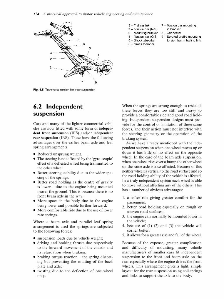
6.2 Independentsuspension
Cars and many of the lighter commercial vehi-cles are now fitted with some form of indepen-dent front suspension (IFS) and/or independent
rear suspension (IRS). These have the followingadvantages over the earlier beam axle and leafspring arrangements.
. Reduced unsprung weight.
. The steering is not affected by the ‘gyro-scopic’effect of a deflected wheel being transmitted tothe other wheel.
. Better steering stability due to the wider spa-cing of the springs.
. Better road holding as the centre of gravityis lower – due to the engine being mountednearer the ground. This is because there is nofront beam axle in the way.
. More space in the body due to the enginebeing lower and possible further forward.
. More comfortable ride due to the use of lowerrate springs.
Where a beam axle and parallel leaf springarrangement is used the springs are subjectedto the following forces:
. suspension loads due to vehicle weight;
. driving and braking thrusts due respectivelyto the forward movement of the chassis andits retardation when braking;
. braking torque reaction – the spring distort-ing but preventing the rotating of the backplate and axle;
. twisting due to the deflection of one wheelonly.
When the springs are strong enough to resist allthese forces they are too stiff and heavy toprovide a comfortable ride and good road hold-ing. Independent suspension designs must pro-vide for the control or limitation of these sameforces, and their action must not interfere withthe steering geometry or the operation of thebraking system.
As we have already mentioned with the inde-pendent suspension when one wheel moves up ordown it has little or no effect on the oppositewheel. In the case of the beam axle suspension,when one wheel rises over a bump the other wheelon the same axle is also affected. Because of thisneither wheel is vertical to the road surface and sothe road holding ability of the vehicle is affected.In a truly independent system each wheel is ableto move without affecting any of the others. Thishas a number of obvious advantages:
1. a softer ride giving greater comfort for thepassengers;
2. better road holding especially on rough oruneven road surfaces;
3. the engine can normally be mounted lower inthe vehicle;
4. because of (1) (2) and (3) the vehicle willcorner better;
5. it allows for a greater rise and fall of the wheel.
Because of the expense, greater complicationand difficulty of mounting, many vehiclemanufacturers of smaller cars fit independentsuspension to the front and beam axle on therear especially where the engine drives the frontwheels. This arrangement gives a light, simplelayout for the rear suspension using coil springsand links to support the axle to the body.
Fig. 6.5 Transverse torsion bar rear suspension
174 A practical approach to motor vehicle engineering and maintenance

The effects of uneven road surfaces and bodyroll on the suspension can be seen in Fig. 6.6.From the illustrations it will be seen that theMacPherson strut arrangement gives the moststable body and wheel alignment. This is onereason why the MacPherson strut is the mostcommon type of suspension fitted to light vehicles.
Learning tasks
1. Explain what is meant by ‘brake torque
reaction’. Illustrate where necessary your
answer with a simple sketch.
2. List a typical sequence of checks that should
be made to find a reported knocking noise
coming from the front off side suspension.
3. What effect would the lowering of the front
suspension have on the steering geometry of
the vehicle? Give reasons for your answer.
Axle location
As already mentioned the leaf spring locates theaxle, but the coil, torsion bar, rubber and air
spring suspension support the vehicle and itsload and remove the unevenness of the roadsurface. They do not locate the wheel assemblyor axle in any way. Extra arms (radius arms) orlinks are fitted to locate the wheels for both foreand aft movement and to resist the turningforces of both driving and braking. A Panhard
rod gives sideways location between the axle andthe body (see Fig. 6.7).
A number of other methods are in use thatlocate the axle. These include the use of tie rods,wishbone and semi-trailing links (Fig. 6.8). Whenan IRS is fitted (as on some of the more expensivevehicles) then the arrangement for location of thewheel assembly can become more complicated.
The method used to attach the links and armsto the body is by the use of rubber bushes. Thereis always a certain amount of ‘give’ in theserubber joints and this is termed compliance.This is generally allowed for in the specificationsgiven by the manufacturer when checking thesuspension for alignment.
Fig. 6.6 Effects of (a) body roll and (b) irregular road surfaces
on suspension geometry
Fig. 6.7 Layout of rigid line axle using coil springs and Panhard
rod
Fig. 6.8 Independent rear suspension and final drive using
semi-trailing links
Suspension systems 175

Learning tasks
1. To which types of suspension arrangements
is the Panhard rod fitted and why to this
particular type?
2. How should the rubber bushes in the sus-
pension be checked for wear?
3. If a driver complained of vehicle instability
especially when cornering or driving over
rough and uneven road surfaces what would
you suspect the fault to be? Give reasons for
your answer.
4. Remove and refit a suspension link, inspect
the bushes for wear and soundness, the link
for signs of accident damage and rust and
the mounting point for signs of wear or rust.
Rubber suspensions
Rubber can be used as the suspension mediumas well as for mountings and pivots. Its mainadvantage is that for small wheel movementsthe ride is fairly soft but it becomes harder aswheel movement increases. It has the advantageof being small, light and compact and willabsorb some of the energy passed to it, unlikea coil spring which gives out almost as muchenergy as it receives. The rubber spring is alsocommonly used on LGVs and trailers. A rubbersuspension unit is shown in Fig. 6.9.
Hydrolastic suspension
This is a combination of rubber and fluid (whichis under pressure). Each wheel is fitted with ahydrolastic unit which consists of a steel cylindermounted on the body of the car. A taperedpiston, complete with a rubber and nylon dia-phragm which is connected to the upper suspen-sion arm, fits in the bottom of the unit. Whenthe wheel moves upwards the piston is alsomoved up and via fluid action compresses therubber spring. The units are connected togetheron the same side by large bore pipes and some ofthe fluid is displaced down the pipe to the otherunit. In this way the tendency for the vehicle topitch (this is the movement of the body fore andaft, that is front to back) is reduced. A hydro-elastic system is shown in Fig. 6.10.
Hydrogas suspension
Sometimes called hydropneumatic this system,shown in Fig. 6.11, is a development of thehydrolastic system. The main difference is that
Fig. 6.9 Rubber suspension unit
Fig. 6.10 Hydrolastic spring displacer unit
176 A practical approach to motor vehicle engineering and maintenance

the rubber is replaced by a gas (usually nitro-gen), hence the term ‘pneumatic’. With thistype the gas remains constant irrespective ofthe load carried. Gas pressure will increaseas volume is reduced. This means that thesuspension stiffens as the load increases. Theunits are connected together in a similarmanner to the hydrolastic suspension and thefluid used is a mixture of water, alcohol and ananti-corrosive agent.
The ride height in both these systems can beraised or lowered by the use of a hydrolasticsuspension pump to give the correct ride heightand ground clearance.
Learning tasks
1. What safety precautions must be observed
when working on pressurized suspension
systems?
2. State the method used for adjusting the ‘ride
height’ on the hydropneumatic suspension
system. Identify any specialized equipment
and fluid type that must be used. Adjust
the ride height to the upper limit specified
by the manufacturer in the repair manual.
3. Identify four units in the suspension that use
rubber bushes to mount the suspension to
the body or chassis.
4. Remove a suspension unit from a vehicle
with hydrolastic or hydrogas suspension.
Identify any worn or defective components.
Replace the unit and adjust the ride height as
necessary.
Active or ‘live’ hydropneumaticsuspension
This system, shown in Fig. 6.12, allows the dri-ver to adjust the ride height (sometimes inaccu-rately referred to as ground clearance) of thevehicle. It also maintains this clearance irrespec-tive of the load being carried. First developed byCitroen it has recently been taken up by a num-ber of other manufacturers. On the Citroenarrangement each suspension arm is supportedby a pneumatic spring.
Connected between the suspension arms atboth front and rear are anti-roll bars. Theseare linked to height correctors by means of
Fig. 6.11 Hydrogas suspension
Fig. 6.12 Simplified layout of hydropneumatic suspension system
Suspension systems 177

control rods. An engine driven pump suppliesoil under pressure to a hydraulic accumulator
and this is connected to the height control orlevelling valves.
As the vehicle is loaded, the downwardmovement of the body causes the rotation ofthe anti-roll bar. This moves the slide valve inthe height correctors and uncovers the port tosupply oil under pressure from the accumulatorto the suspension cylinders. When the bodyreaches the predetermined height (which canbe varied by the driver moving a lever insidethe vehicle), the valve moves to the ‘neutral’position. Removal of the load causes thevalve to vent oil from the cylinder back to thereservoir.
A delay device is incorporated to preventrapid oil flow past the valve when the wheelcontacts a bump. This prevents the valve fromcontinuously working and giving unsatisfactoryoperation.
In some systems a third spring unit is fittedbetween the two spring units on the front axleand between the two spring units on the rearaxle. This gives a variable spring rate and rollstiffness, i.e. the suspension is active. Thesystem is controlled by an ECU (electroniccontrol unit) which senses steering wheelmovement, acceleration, speed and bodymovement and reacts accordingly via controlvalves to regulate the flow of oil to and fromthe suspension units. Under normal drivingconditions the ECU operates the solenoidvalve which directs fluid to open the regulatorvalves. This allows fluid to flow between thetwo outer spring units and the third springunits via the damper units to give a soft ride.During harder driving the solenoid valve isswitched off automatically relieving the regu-lator valves which close, preventing fluid flowbetween the spring units. The third springunit being isolated and not in use gives afirmer ride.
There are a number of benefits of thissystem:
. it automatically adjusts the spring and dam-per rate to suit road conditions and drivingstyles;
. it can provide a soft and comfortable rideunder normal driving conditions;
. it will stiffen to give better road holding dur-ing hard driving;
. a near constant ride height can be achievedirrespective of the load on the vehicle.
Learning tasks
1. A number of safety precautions must be
observed before dismantling this type of
suspension system. What are these and
why should they be carried out?
2. What are the main advantages/disadvan-
tages of this type of suspension system over
a mechanical system?
3. The oil in the system should be changed at
regular intervals. How often is this and
what is the correct procedure? State the
correct type of fluid that must be used in
the system.
4. Remove and refit a hydropneumatic suspen-
sion unit. Take care when undoing pipe
unions that the pipes are not damaged.
Observe all the safety precautions necessary.
Make a note of all defects, re-pressurize the
system and check for leaks.
Rear wheel ‘suspension steer’
In some systems the rear suspension isarranged to produce a steering effect whencornering. As the suspension is deflected theroad wheel toes-in due to the arc of movementof the semi-trailing link. This producesundersteer on cornering (it gives a small degreeof same direction rear-steer). Figure 6.13 showsone example that will give:
. toe-in when braking;
. understeer when cornering;
. stability in straight line running and whenchanging lanes.
A simpler suspension arrangement is shown inFig. 6.14 that produces toe-in under similaroperating conditions.
Air suspension
Some vehicle manufacturers fit air suspensionunits in place of the conventional coil springs.A typical example with electronically con-trolled air suspension is shown in Fig. 6.15.Three switches, positioned near the steeringcolumn, control the ride height: the upperswitch raises the vehicle by approximately40mm for driving through deep water or overrough ground; the middle switch gives a similarride height to the coil-sprung model; the lowerswitch lowers the vehicle approximately 60mmbelow the standard setting to enable easier
178 A practical approach to motor vehicle engineering and maintenance

loading and for getting in and out. A numberof automatic adjustments such as loweringthe vehicle when driving over 50mph toreduce wind resistance and raising the vehicleif it should become grounded are programmedinto the ECU and operate independently ofthe driver.
Another system uses a digital controller(ECU) which reacts to suspension accelerationand ride height by varying the oil pressure. Itwill also adjust damper action by reference tobody movement.
Some manufacturers make ride height levellers(Fig. 6.16), which are shock absorbers that willraise the rear of the vehicle to its normal rideheight when loaded. The system is operatedthrough a switch, electric motor and compressor;the dampers are pumped up via air pipes con-necting the units together.
The suspension damper has to perform a num-ber of functions. These are:
. absorb road surface variations;
. insulate the noise from the vehicle body;
. give resistance to vehicle body pitch underbraking and acceleration;
. offer resistance to roll when cornering.
A passive mechanical system to tackle eachof these tasks is impossible as the rate ofthe damper must be varied to suit differingcircumstances and handling characteristics.Shock absorber manufacturers have madeprovision for some control over the dampingrate by making them adjustable, but once seteven these are not suitable for all applicationsand uses.
With this in mind many of the new suspensionsystems are active; in other words they will oper-ate continuously adjusting to pre-set limits thesuspension spring rate. One system uses an ECUwhich receives information on cruising, suspen-sion condition, body roll and pitch. It thendirects air from the compressor to the suspen-sion units to give the correct spring rate and rideheight for the load carried.
Learning tasks
1. What is the purpose of the ECU and elec-
tronic sensors in an active suspension sys-
tem? What attention do these units require
and at what intervals should checks be car-
ried out?
Fig. 6.13 Multi-link rear suspension
Suspension systems 179
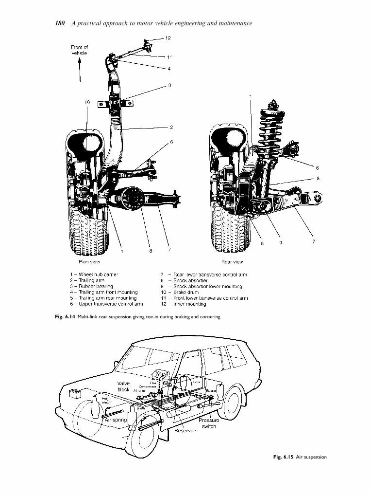
Fig. 6.14 Multi-link rear suspension giving toe-in during braking and cornering
Fig. 6.15 Air suspension
180 A practical approach to motor vehicle engineering and maintenance

2. On some models the system is connected
to the anti-lock braking system. Explain in
simple terms the reason for this and how it
operates.
3. List the maintenance requirements for one
of the ‘active’ suspension systems with
which you are familiar.
4. Draw up a work schedule for removing a
suspension unit from a vehicle. Special note
should be made of the safety aspects of the
task.
5. Remove an ECU from an active suspension
system, check the terminals for corrosion
or damage and clean with appropriate
spray cleaner where necessary. Ensure
that the mounting surface is clean and
free from rust. Refit the ECU taking
special care when refitting the terminal
connector.
6.3 Suspension dampers
The function of the suspension damper is not toincrease the resistance to the spring deflectingbut to control the oscillation of the spring (this isthe continuing up and down movement of thespring after going over a bump or hollow in theroad surface). In other words it absorbs energygiven to the spring, hence the more commonname of shock absorber. It does this by forcingoil in the damper to do work by passing itthrough holes in the piston and converting theenergy of the moving spring into heat which ispassed to the atmosphere.
Two main categories of dampers are in com-mon use: the direct-acting (usually telescopic)and the lever arm.
The twin-tube telescopic damper
This type is usually located between the chassisand the axle so that on both bump and reboundoil is forced through the holes in the piston.The reservoir is used to accommodate theexcess oil that is displaced as a result of thevolume in the upper cylinder being smaller.If oil is lost and air enters the damper it willaffect its performance and it will become‘spongy’ in operation. This will have an effecton the stability of the vehicle especially whencornering, travelling over rough ground,uneven surfaces and on braking or accelerat-ing. When checking for correct operation dis-connect one end of the damper and check theamount of resistance to movement. Figure 6.17shows a telescopic shock absorber.
Gas-pressurized dampers
A single tube is used as the cylinder in which thepiston operates. It is attached to the car body andsuspension by rubber bushes to reduce noise andvibration and to allow for slight sideways move-ments as the suspension operates. A chamber inthe unit, sealed by a free piston, contains an inertgas that is under pressure when the damper isfilled with oil. As the suspension operates thepiston moves down the cylinder and oil is forcedthrough the ‘bump’ valve to the upper chamber;excess oil that cannot be accommodated in theupper chamber because of the rod moves the freepiston to compress the gas. On rebound the oil ismade to pass through the ‘rebound’ valve in thepiston; by varying the size of the holes in thevalves the resistance of each stroke can be alteredto suit different vehicle applications. Thisarrangement is most commonly fitted to theMacPherson strut suspension systems. The mainadvantages of the single-tube damper are:
. it can displace a large volume of fluid withoutnoise or fluid aeration;
. it is fairly consistent in service even whenoperating at large angles to the suspensionmovement;
. it has good dissipation of heat to the air flow.
Checking damper operation
Two tests are normally used to check whetherthe dampers are serviceable without removingthem from the vehicle. The bounce test involvespushing down on each corner of the vehicle
Fig. 6.16 Height levellers in the rear axle
Suspension systems 181

Fig. 6.17 Telescopic shock absorber (a) bump or compression stroke, (b) rebound or extension stroke
182 A practical approach to motor vehicle engineering and maintenance

and observing the up and down movementof the body as it comes to its rest position.The second method involves the use of someform of tester of which there are severaltypes available. One type uses an eccentric rollerarrangement that the vehicle is driven ontoto produce the required movement of the sus-pension. In another the vehicle is driven up acollapsible ramp; when set the ramp is dropped.Both types give a graphical printout of the testthat shows the oscillations of the suspension.
Materials used in suspensions
. Road springs These are made from a siliconmanganese steel as they must withstand veryhigh stresses and fatigue yet still retain elasti-city and strength.
. Suspension links Here a nickel steel is usedwhich gives elasticity together with tough-ness.
. Bushes These are usually made from rubberto reduce vibration, noise and the need forlubrication.
6.4 Maintenance checks
General rules
There are a number of general rules that shouldbe observed when carrying out maintenancechecks and adjustments; and there are alsomethods of protecting the system againstaccidental damage during repair operations onthe suspension system. These are listed below:
. preliminary vehicle checks – see the vehiclereport sheet;
. safety – the proper use of lifting supportingand choking equipment;
. safe use of special tools such as coil springcompressor, high-pressure lubricants andhigh-pressure hydraulic equipment;
. care when working with and disposing oftoxic and corrosive fluids;
. checking of the suspension thoroughly beforeroad testing.
Checking suspension alignmentand geometry
To check the alignment of the suspension a fourwheel aligner is used. The gauges are located oneach rear wheel and the light on the each front
wheel; the light shines onto the gauge down eachside of the vehicle. This will show any misalign-ment between the front and rear wheels whichcan then be identified, helping to prevent tyrescrub, steering pulling to one side or crabbing ofthe vehicle down the road. The lights also shineacross the front of the vehicle to check frontwheel alignment. When all four gauges give thecorrect readings, the vehicle will drive down theroad in a straight line.
Learning tasks
1. What are the symptoms of faulty dampers?
How will the driver notice this problem?
How should they be checked for correct
operation?
2. Draw up a work schedule for stripping and
rebuilding a MacPherson strut-type suspen-
sion. Name any special tools that should be
used and identify any safety precautions that
should be observed?
3. For each of the following suspension faults:
describe the fault (what is wrong?); identify
the symptom (how will the driver notice?);
state the probable cause (what has caused
the fault?); and give the preventative or cor-
rective action that should be taken.
(a) Excessive uneven tyre wear
(b) Excessive component wear
(c) Premature failure of component
(d) Vibration and/or noise from suspension
(e) Uneven braking
(f) Steering pulling to one side
(g) Incorrect trim height
(h) Axle misalignment
(i) Excessive pitch or roll
(j) Vehicle instability over rough road surfaces
(k) Poor handling and ride quality
(l) Noisy suspension
Practical assignment –suspension system
Introduction
At the end of this assignment you should be able to:
. carry out a visual inspection
. remove and replace a
– MacPherson strut
– coil spring
Suspension systems 183

– shock absorber, checking for correct opera-
tion
– suspension bush. check alignment of suspension. make a report together with recommendations
Tools and equipment
. A vehicle fitted with suitable suspension
. A vehicle lift or jack and axle stands
. Workshop manual
. Selection of tools to include specialist equipment
such as a spring compressor
Objective
. To check operation of damper
. To replace suspension bushes
. To check ‘free height’ of coil spring
. To investigate oil leaks
. To replace worn/damaged components
Activity
1. After suitably raising and supporting the vehicle
remove the wheels (do not support the vehicle
under the suspension to be removed).
2. Observe and note the type of suspension, e.g.
coil spring, leaf spring, torsion bar, rubber, etc.
3. Make a simple sketch of the layout.
4. Before cleaning around the mounting points
look for signs of:
(a) insecure or loose components
(b) places where dirt may be rubbed off by
something catching
(c) bright or rusty streak marks where body or
chassis may be cracked
(d) rust where thickness of material may be
reduced to a failure level
(e) excessively worn components
(f ) accident damage to body or components
5. Remove suspension and dismantle where
necessary.
6. Check operation of damper.
7. Reassemble suspension (replacing any worn/
broken components) according to manufac-
turer’s manual.
8. Check for correct assembly and tightness of all
mounting bolts before fitting wheel.
9. Complete an inspection report and recommen-
dations for the customer.
Checklist
Vehicle
Removal and refitting
MacPherson strut
Coil spring
Leaf spring
Shock absorber
Rubber suspension bush
Dismantle and reassemble
MacPherson strut
Shock absorber
Checking and adjusting
Castor angle
Camber angle
King pin inclination
Toe-out on turns
Wheel alignment
Axle alignment
Body alignment
Ride height
Investigating and reporting
Rubber
Hydrogas
Hydrolastic
Hydropneumatic
Coil spring
Leaf spring
Air
Student’s signature
Supervisor’s signature
Self assessment questions
1. The rear suspension system shown in Fig. 6.13:
(a) is a trailing arm type
(b) is a torque tube transaxle type
(c) has no unsprung weight
(d) is a dead axle
2. A principal task of the suspension dampers:
(a) is to dampen out spring vibrations
(b) is to allow the use of weaker springs
(c) is to keep the vehicle upright on corners
(d) is to eliminate axle tramp under braking
184 A practical approach to motor vehicle engineering and maintenance

3. Coil spring suspension systems:
(a) are lighter than leaf spring suspension
systems
(b) require the use of radius arms to transmit
driving and braking forces from the wheels
to the vehicle frame
(c) do not require the use of suspension dam-
pers
(d) are only suitable for small vehicles
4. With independent front suspension:
(a) the engine can be set lower in the frame
because there is no axle beam
(b) vertical movement of a wheel on one
side of the vehicle will cause the wheel
on the opposite side to move in a similar
way
(c) double acting dampers are essential
(d) tyre wear is lower than it is on beam axle
systems
5. In leaf spring type suspension systems:
(a) extra tie rods are needed in order to trans-
mit driving and braking forces from the
wheels to the vehicle body
(b) both ends of the spring are rigidly fixed to
the chassis
(c) driving and braking forces are trans-
mitted to the chassis through the spring
leaves
(d) extra strong dampers are required to cope
with the greater tendency for this type of
suspension to vibrate
6. Figure 6.7 shows a Panhard rod fitted to a coil
spring suspension. The purpose of this rod is to:
(a) limit vertical movement of the vehicle body
relative to the road wheels
(b) transmit cornering forces between the
vehicle body and the axle
(c) absorb braking torque reaction
(d) secure the brake caliper to the vehicle
frame
7. In a hydro pneumatic suspension unit:
(a) ride height is fixed at a constant level
(b) ride height is varied by introducing or
removing hydraulic fluid from the chamber
below the gas diaphragm
(c) gas is pumped in and out of the chamber
above the gas diaphragm
(d) the equivalent spring rate is constant
8. An active suspension system:
(a) uses an ECU to adjust suspension charac-
teristics to suit driving conditions
(b) is only suitable for use on racing cars
(c) has fewer working parts than a non-active
type suspension system
(d) can only work on torsion bar type suspension
Suspension systems 185

7Braking systems
Topics covered in thischapter
Hydraulic braking systems
Drum brakes
Disc brakes
Master cylinder
Wheel cylinders
Brake fluid
Braking efficiency
7.1 Vehicle brakingsystems
The purpose of the braking system is to slowdown or stop the vehicle and, when the vehicleis stationary, to hold the vehicle in the chosenposition. When a vehicle is moving it containsenergy of motion (kinetic energy) and thefunction of the braking system is to convertthis kinetic energy into heat energy. It does sothrough the friction at the brake linings andthe brake drum, or the brake pads and thedisc.
Some large vehicles are fitted with secondarybraking systems that are known as retarders.Examples of retarders are exhaust brakes andelectric brakes. In all cases, the factor that ulti-mately determines how much braking can beapplied is the grip of the tyres on the drivingsurface.
7.2 Types of brakes
Two basic types of friction brakes are in com-mon use on vehicles; these are:
1. the drum brake2. the disc brake
The drum brake
Figure 7.1 shows a drum brake as used on alarge vehicle. This cut-away view shows thatthe linings on the shoes are pressed into contactwith the inside of the drum by the action of thecam. In this case the cam is partially rotated bythe action of a compressed air cylinder. Theroad wheel is attached to the brake drum bymeans of the wheel studs and nuts.
A brake of this type has a leading shoe and atrailing shoe. The leading shoe is the one whoseleading edge comes into contact with the drumfirst, in the direction of rotation. A leading shoeis more powerful than a trailing shoe and thisshows up in the wear pattern because a leadingshoe generally wears more than a trailing shoeowing to the extra work that it does.
Fig. 7.1 A cam operated drum brake

The disc brake
Figure 7.2 shows the principle of the disc brake.The road wheel is attached to the disc and theslowing down or stopping action is achieved bythe clamping action of the brake pads on thedisc.
In this brake the disc is gripped by the twofriction pads. When hydraulic pressure isapplied to the hydraulic cylinder in the caliperbody, the pressure acts on the piston and pushesthe brake pad into contact with the disc. Thiscreates a reaction force which causes the pins toslide in the carrier bracket and this action pullsthe other pad into contact with the disc so thatthe disc is tightly clamped by both pads.
7.3 Hydraulic operation ofbrakes
The main braking systems on cars and mostlight commercial vehicles are operated byhydraulic systems. At the heart of a hydraulicbraking system is the master cylinder as this iswhere the pressure that operates the brakes isgenerated.
Principle of the hydraulic system
The small diameter master cylinder is connectedto the large diameter actuating cylinder by a
strong metal pipe. The cylinders and the pipeare filled with hydraulic fluid. When a force isapplied to the master cylinder piston a pressure iscreated that is the same at all parts of the interiorof the system. Because pressure is the amount offorce acting on each square millimetre of surface,the force exerted on the larger piston will begreater than the force applied to the small piston.In the example shown in Fig. 7.3 the force of 100Newtons on an area of 400 square millimetres ofthe master cylinder piston creates a pressure of0.25 Newtons per square millimetre. The pistonof the actuating cylinder has an area of 800square millimetres and this gives a force of 200Newtons at this cylinder.
The master cylinder
The part of the hydraulic braking system wherethe hydraulic operating pressure is generated isthe master cylinder. Force is applied to the mas-ter cylinder piston by the action of the driver’sfoot on the brake pedal.
In the example shown in Fig. 7.4 the action isas follows. When force is applied to the pushrod the piston moves along the bore of themaster cylinder to take up slack. As soon asthe lip of the main rubber seal has covered theby-pass hole, the fluid in the cylinder, and thesystem to which it is connected, is pressurised.When the force on the brake pedal and themaster cylinder push rod is released, the returnspring pushes the piston back and the hydraulicoperating pressure is removed. The action of themain piston seal ensures that the master cylinderremains filled with fluid.
Fig. 7.2 A disc brake
Fig. 7.3 The principle of a hydraulic braking system. The
hydraulic pressure is equal at all parts of the system
Braking systems 187

7.4 Wheel cylinders
The hydraulic cylinders that push the drum brakeshoes apart, or apply the clamping force in thedisc brake, are the wheel cylinders. There are twoprincipal types of wheel cylinders, a single actingcylinder and a double acting cylinder.
The single acting wheel cylinder
The space in the wheel cylinder, behind therubber seal and piston, is filled with brakefluid. Pressure from the master cylinder isapplied to the wheel cylinders through pipes.Increased fluid pressure pushes the piston outand this force is applied to the brake shoe orbrake pad.
Double acting wheel cylinder
Figure 7.6 shows that the double acting wheelcylinder has two pistons and rubber seals.Hydraulic pressure applied between the pistonspushes them apart. The pistons then act on thebrake shoes and moves the linings into contactwith the inside of the brake drum.
7.5 The hand-brake
The handbrake (parking brake) is required tohold the vehicle in any chosen position when thevehicle is stationary. In addition to its functionas a parking brake, the handbrake is also usedwhen making hill starts and similar manoeuvres.The handbrake also serves as an emergencybrake in the event of failure of the main brakingsystem. Figure 7.7 shows the layout and mainfeatures of a handbrake for a car or light van.The vehicle has trailing arm rear suspension andthe swivel sector pivots (4) are needed to guidethe cable on these suspension arms. The purposeof the compensator is ensure that equal brakingforce is applied to each side of the vehicle. The
Fig. 7.4 A simple type of hydraulic master cylinder
Fig. 7.5 A single acting hydraulic wheel cylinder
Fig. 7.6 A double acting hydraulic wheel cylinder (a) Rover 200
series drum brake, (b) a double acting wheel cylinder
188 A practical approach to motor vehicle engineering and maintenance

handbrake normally operates through thebrakes at the rear of the vehicle.
With normal use, the brake linings will wearand it is also possible that the handbrake cablemay stretch a little. In order to keep the hand-brake working properly it is provided with anadjustment, as shown in Fig. 7.8.
The nut (2) is the adjusting nut and the nut (1)is the lock nut. In order to adjust the handbrake,the rear of the vehicle must be lifted so that thewheels are clear of the ground. The normalsafety precautions must be observed and thewheels should be checked for freedom of rota-tion after the cable has been adjusted.
7.6 Split braking systems
The split braking circuit provides for emergen-cies such as a leak in one area of the brakingsystem. There are various methods of providingsplit braking circuits and some of these areshown in Figs 7.9(a, b & c).
Front/rear split
Fig. 7.9(a) shows how the front brakes are oper-ated by one part of the master cylinder and the
Fig. 7.7 A handbrake system
Fig. 7.8 Handbrake cable adjustment
Fig. 7.9 (a) Front/Rear split of braking system, (b) diagonal split
of braking system, (c) front axle and one rear wheel split
Braking systems 189
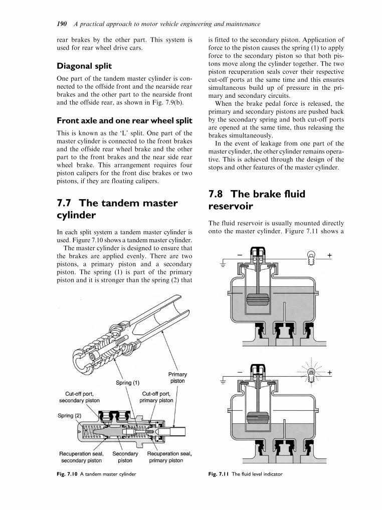
rear brakes by the other part. This system isused for rear wheel drive cars.
Diagonal split
One part of the tandem master cylinder is con-nected to the offside front and the nearside rearbrakes and the other part to the nearside frontand the offside rear, as shown in Fig. 7.9(b).
Front axle and one rear wheel split
This is known as the ‘L’ split. One part of themaster cylinder is connected to the front brakesand the offside rear wheel brake and the otherpart to the front brakes and the near side rearwheel brake. This arrangement requires fourpiston calipers for the front disc brakes or twopistons, if they are floating calipers.
7.7 The tandem mastercylinder
In each split system a tandem master cylinder isused. Figure 7.10 shows a tandemmaster cylinder.
The master cylinder is designed to ensure thatthe brakes are applied evenly. There are twopistons, a primary piston and a secondarypiston. The spring (1) is part of the primarypiston and it is stronger than the spring (2) that
is fitted to the secondary piston. Application offorce to the piston causes the spring (1) to applyforce to the secondary piston so that both pis-tons move along the cylinder together. The twopiston recuperation seals cover their respectivecut-off ports at the same time and this ensuressimultaneous build up of pressure in the pri-mary and secondary circuits.
When the brake pedal force is released, theprimary and secondary pistons are pushed backby the secondary spring and both cut-off portsare opened at the same time, thus releasing thebrakes simultaneously.
In the event of leakage from one part of themaster cylinder, the other cylinder remains opera-tive. This is achieved through the design of thestops and other features of the master cylinder.
7.8 The brake fluidreservoir
The fluid reservoir is usually mounted directlyonto the master cylinder. Figure 7.11 shows a
Fig. 7.10 A tandem master cylinder Fig. 7.11 The fluid level indicator
190 A practical approach to motor vehicle engineering and maintenance

fluid reservoir equipped with a fluid levelindicator. The fluid reservoir is normallymade from translucent plastic and, providedit is kept clean, it is possible to view the fluidlevel by under bonnet inspection. The reser-voir is fitted with an internal dividing panelensuring that one section remains operativeshould the other section develop a loss offluid. The fluid level indicator operates awarning light. Should the fluid level dropbelow the required level, the switch contactswill close and the warning light on the dashpanel will be illuminated.
7.9 Brake pipes and hoses
The hydraulic pressure created at the mastercylinder is conveyed to the wheel brakesthrough strong metal pipes, where they can beclipped firmly to the vehicle, and through flex-ible hoses where there is relative movementbetween the parts, for example axles and steeredwheels and the vehicle frame.
7.10 The brake servo
It is common practice to provide some meansof increasing the force that the driver appliesto the brake pedal. The servo is the device
which allows the driver to apply a large brak-ing force by the application of relatively lightforce from the foot. The amount of increasedforce that is produced by the servo is depen-dent on the driver’s effort that is applied tothe brake pedal. This ensures that brakingeffort is proportional to the force applied tothe brake pedal.
On petrol engined vehicles, manifold vacuumis used to provide the boost that the servo gen-erates. On diesel engined vehicles there is oftenno appreciable manifold vacuum, owing to theway in which the engine is governed. In thesecases, the engine is equipped with a vacuumpump that is known as an exhauster.
The master cylinder (1) is firmly bolted tothe servo unit on one side and, on the otherside, the servo unit is firmly bolted to thevehicle bulkhead (4). The brake pedal effortis applied to the servo input shaft and this inturn pushes directly on the master cylinderinput piston. Figure 7.13 shows the servo inmore detail.
At this stage you should concentrate onthe flexible diaphragm, the sealed container,the two chambers (A) and (B) and thevacuum connection. The valve body andthe control piston are designed so that whenthe brakes are off, the manifold vacuum willdraw out air and create a partial vacuum inchambers (A) and (B) on both sides of thediaphragm.
When force is applied to the brake pedal,the control piston closes the vacuum port andeffectively shuts off chamber (B) from cham-ber (A). At this stage, the control pistonmoves away from the control valve and atmo-spheric pressure air is admitted into chamber(B). The greater pressure in chamber (B),compared with the partial vacuum in cham-ber (A), creates a force that adds to the pedaleffort applied by the driver. The servo outputrod pushes direct on to the master cylinderpiston, as shown in Fig. 7.14, so that there isno lost motion and the resulting force appliedto the master cylinder is proportional to theeffort that the driver applies to the brakepedal.
It is common practice to fit a non-returnvalve in the flexible pipe, between the manifoldand the servo unit, as shown in Fig. 7.15. Thisvalve serves to retain vacuum in the servo afterthe engine is stopped and also prevents petrolengine vapours and ‘backfire’ gases from enter-ing the servo.Fig. 7.12 A vacuum servo
Braking systems 191

7.11 Brake adjustment
During normal usage, the brake friction surfaceswear. In disc brakes this means that the actuatingpistons push the pads closer to the disc and thelight rubbing contact between friction material(pads) and the discs is maintained; disc brakesare thus ‘self adjusting’. There is some displace-ment of brake fluid from the reservoir to thewheel cylinders and this will be noticed by the
lowering of fluid level in the reservoir. When newbrake pads are fitted there may be an excess offluid in the system, if the fluid was topped upwhen the brakes were in a worn condition.
When the friction linings on brake shoeswear, the gap between the lining and the insideof the brake drum increases. To compensate forthis wear, drum brakes are provided with adjus-ters. Adjusters take two forms; 1) manual adjus-ters, and 2) automatic adjusters.
Fig. 7.13 Details of a vacuum servo
Fig. 7.14 Vacuum servo and master cylinder Fig. 7.15 The non-return valve in the vacuum pipe
192 A practical approach to motor vehicle engineering and maintenance

Manual brake adjuster
Figure 7.16 shows a type of manual brake adjus-ter that has been in use for many years. Thethreaded portion is provided with a slotted partthat permits it to be rotated by means of a lever.The adjuster is accessed through a hole in thebrake drum and the lever, probably a screwdri-ver, is applied through this hole. The two endsof the adjuster are located onto the brake shoesand ‘screwing out’ the threaded portion pushesthe shoes apart until the correct lining to drumclearance is obtained.
Automatic brake adjuster
This adjustment mechanism relies on the move-ment of the operating mechanism to operatea ratchet and pawl. The mechanism togetherwith part of the two brake shoes is shown inFig. 7.17.
The ratchet is a small toothed wheel that isfixed to the adjusting bolt. The pawl is on theend of the adjusting lever and it engages withthe ratchet. The connecting rod which is intwo parts, (A) and (B), and fits between thetwo brake shoes. The pawl is pulled lightlyinto contact with the ratchet by the spring.Operation of the brake shoes pushes the shoesapart and this creates a clearance at the end ofthe connecting rod. When there is sufficientclearance, the ratchet will rotate by one notch,which increases the length of the connecting
rod and takes up the excess clearance betweenthe shoes and the drum.
These mechanisms work well when they areproperly maintained and service schedules mustbe properly observed to ensure that the brakesare maintained in good order.
7.12 Wear indicators
The purpose of the friction pad wear indicator isto alert the driver to the fact that the pads haveworn thin. The warning light on the dash panelis illuminated when the pads have worn by acertain amount. Figure 7.18 shows a pair ofbrake pads. One of the pads is equipped with apair of wires whose ends are embedded in thefriction material of the pad. When the pad wears
Fig. 7.16 A manual brake adjuster
Fig. 7.17 An automatic brake adjuster
Braking systems 193
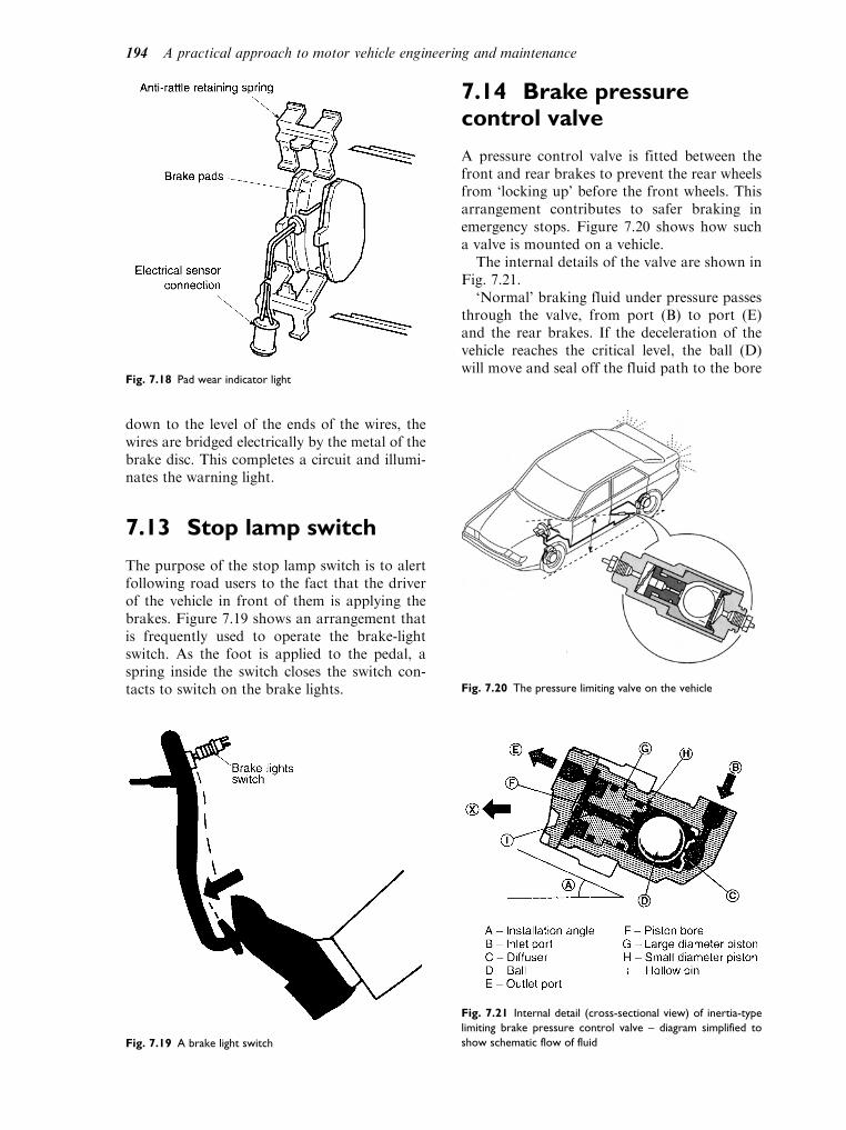
down to the level of the ends of the wires, thewires are bridged electrically by the metal of thebrake disc. This completes a circuit and illumi-nates the warning light.
7.13 Stop lamp switch
The purpose of the stop lamp switch is to alertfollowing road users to the fact that the driverof the vehicle in front of them is applying thebrakes. Figure 7.19 shows an arrangement thatis frequently used to operate the brake-lightswitch. As the foot is applied to the pedal, aspring inside the switch closes the switch con-tacts to switch on the brake lights.
7.14 Brake pressurecontrol valve
A pressure control valve is fitted between thefront and rear brakes to prevent the rear wheelsfrom ‘locking up’ before the front wheels. Thisarrangement contributes to safer braking inemergency stops. Figure 7.20 shows how sucha valve is mounted on a vehicle.
The internal details of the valve are shown inFig. 7.21.
‘Normal’ braking fluid under pressure passesthrough the valve, from port (B) to port (E)and the rear brakes. If the deceleration of thevehicle reaches the critical level, the ball (D)will move and seal off the fluid path to the bore
Fig. 7.18 Pad wear indicator light
Fig. 7.19 A brake light switch
Fig. 7.20 The pressure limiting valve on the vehicle
Fig. 7.21 Internal detail (cross-sectional view) of inertia-type
limiting brake pressure control valve – diagram simplified to
show schematic flow of fluid
194 A practical approach to motor vehicle engineering and maintenance

of the valve (F). At this point the rear brakesare effectively ‘cut off ’ from the front brakesand the pressure on the rear brakes is held at itsoriginal level. Further pressure on the brakepedal increases the front brake pressure with-out increasing the rear brake pressure. Depend-ent on the design of the valve, further brakepedal pressure will cause the piston (G–H) tomove and increase the pressure in the rearbrake line.
When the deceleration falls, the ball will ‘roll’back to its seat on the diffuser (C) and the pres-sure throughout the braking system is stabilised.
7.15 Brake fluid
Brake fluid must have a boiling temperature ofnot less than 190 C, and a freezing temperaturenot higher than 40 C. Brake fluid is hygro-scopic, which means that it absorbs water fromthe atmosphere. Water in brake fluid affects itsboiling and freezing temperatures, which is oneof the reasons why brake fluid needs to bechanged at the recommended intervals.
Brake fluid is normally based on vegetable oiland its composition is carefully controlled toensure that it is compatible with the rubber sealsand not corrosive to the metal parts. Some man-ufacturers use mineral oil as a base for brakefluids and their systems are designed to workwith this fluid. It is important always to use onlythe type of fluid that a vehicle manufacturerrecommends for use in their vehicles.
7.16 Braking efficiency
The concept of braking efficiency is based onthe ‘idea’ that the maximum retardation (rate ofslowing down) that can be obtained from avehicle braking system is gravitational acceler-ation g¼ 9.8m/s2. The actual retardation
obtained from a vehicle is expressed as apercentage of ‘g’ and this is the braking efficiency.For example, suppose that a vehicle braking sys-tem produces a retardation of 7m/s2. The brakingefficiency¼ (7/9.8) 100¼ 71%. Because of thephysics of vehicle dynamics the braking efficiencycan be obtained without actually measuringdeceleration. This is so because the total weightof the vehicle divided by the sum of the brakingforces applied between the tyres and the drivingsurface produces the same result. Brake testingequipment, as used in garages, uses this principleto measure braking efficiency.
The left (F1) and right (F2) front brakingforces are measured and recorded. The vehicleis moved forward so the that the rear wheels areon the rollers. The test procedure is repeated andthe two rear wheel braking forces (F3) and (F4)are recorded. The four forces are added togetherand divided by the weight of the vehicle.
For example, in a certain brake test on avehicle weighing 1 700 kg, the four brakingforces add up to 1 070 kg. This gives a brakingefficiency of (1 070/1 700) 100¼ 70%. Oftenthe data relating to a particular vehicle is con-tained on a chart kept near the test bay.
The regulations regarding braking efficiencyand the permitted differences in braking, fromside to side of the vehicle, together with otherdata are contained in the tester’s manual. Anytechnician carrying out brake tests must famil-iarise themselves with the current regulations.
7.17 Anti lock brakingsystem (ABS)
The term ABS covers a range of electronicallycontrolled systems that are designed to provideoptimum braking in difficult conditions. ABSsystems are used on many cars, commercialvehicles and trailers.
The purpose of anti-skid braking systems is toprovide safer vehicle handling in difficult condi-tions. If wheels are skidding it is not possible tosteer the vehicle correctly and a tyre that is stillrolling, not sliding, on the surface will provide abetter braking performance. ABS does notusually operate under normal braking. It comesinto play in poor road surface conditions, such asice, snow, water, etc., or during emergency stops.
Figure 7.23 shows a simplified diagram of anABS system, which gives an insight into the waythat such systems operate.
Fig. 7.22 Roller-type brake tester measuring the braking force
at each wheel
Braking systems 195
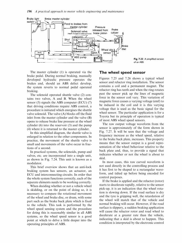
The master cylinder (1) is operated via thebrake pedal. During normal braking, manuallydeveloped hydraulic pressure operates thebrakes and, should an ABS defect develop,the system reverts to normal pedal operatedbraking.
The solenoid operated shuttle valve (2) con-tains two valves, A and B. When the wheelsensor (5) signals the ABS computer (ECU) (7)that driving conditions require ABS control, aprocedure is initiated which energises the shuttlevalve solenoid. The valve (A) blocks off the fluidinlet from the master cylinder and the valve (B)opens to release brake line pressure at the wheelcylinder (6) into the reservoir (3) and the pump(4) where it is returned to the master cylinder.
In this simplified diagram, the shuttle valve isenlarged in relation to the other components. Inpractice, the movement of the shuttle valve issmall and movements of the valve occur in frac-tions of a second.
In practical systems, the solenoids, pump andvalves, etc. are incorporated into a single unit,as shown in Fig. 7.24. This unit is known as amodulator.
This brief overview shows that an anti-lockbraking system has sensors, an actuator, anECU and interconnecting circuits. In order thatthe whole system functions correctly, each of theseparate elements needs to be working correctly.
When deciding whether or not a vehicle wheelis skidding, or on the point of doing so, it isnecessary to compare the rotational movementof the wheel and brake disc, or drum, with somepart such as the brake back plate which is fixedto the vehicle. This task is performed by thewheel speed sensing system and the procedurefor doing this is reasonably similar in all ABSsystems, so the wheel speed sensor is a goodpoint at which to delve a little deeper into theoperating principles of ABS.
The wheel speed sensor
Figures 7.25 and 7.26 shows a typical wheelsensor and reluctor ring installation. The sensorcontains a coil and a permanent magnet. Thereluctor ring has teeth and when the ring rotatespast the sensor pick up the lines of magneticforce in the sensor coil vary. This variation ofmagnetic force causes a varying voltage (emf) tobe induced in the coil and it is this varyingvoltage that is used as the basic signal for thewheel sensor. The particular application is for aToyota but its principle of operation is typicalof most ABS wheel speed sensors.
The raw output voltage waveform from thesensor is approximately of the form shown inFig. 7.27. It will be seen that the voltage andfrequency increase as the wheel speed, relativeto the brake back plate, increases. This propertymeans that the sensor output is a good repre-sentation of the wheel behaviour relative to theback plate and, thus, to provide a signal thatindicates whether or not the wheel is about toskid.
In most cases, this raw curved waveform isnot used directly in the controlling process andit has first to be shaped to a rectangular wave-form, and tidied up before being encoded forcontrol purposes.
If the brake is applied and the reluctor (rotor)starts to decelerate rapidly, relative to the sensorpick-up, it is an indication that the wheel rota-tion is slowing down. If the road surface is dryand the tyre is gripping well, the retardation ofthe wheel will match that of the vehicle andnormal braking will occur. However, if the roadsurface is slippery, a sudden braking applicationwill cause the reluctor rotor and road wheel todecelerate at a greater rate than the vehicle,indicating that a skid is about to happen. Thiscondition is interpreted by the electronic control
Fig. 7.23 A simplified version
of an ABS
196 A practical approach to motor vehicle engineering and maintenance

unit. Comparisons are made with the signalsfrom the other wheel sensors and the brake linepressure will be released automatically, for suf-ficient time (a fraction of a second) to preventthe wheel from locking.
In hydraulic brakes, on cars the pressurerelease and re-application is achieved by solenoidvalves, a pump and a hydraulic accumulator and
Fig. 7.24 ABS modulator
Fig. 7.25 ABS wheel sensor
Fig. 7.26 The basic principle of the ABS sensor
Fig. 7.27 The voltage waveform of the ABS sensor output
Braking systems 197

these are normally incorporated into one unitcalled the modulator. The frequency of ‘pulsing’of the brakes is a few times per second, depend-ing on conditions, and the pressure pulsationscan normally be felt at the brake pedal.
With air brakes on heavy vehicles, the princi-ple is much the same, except that the pressure isderived from the air braking system and theactuator is called a modulator. The valves thatrelease the brakes during anti-lock operation aresolenoid operated on the basis of ECU signals,and the wheel sensors operate on the same prin-ciple as those on cars.
As for the strategy that is deployed to deter-mine when to initiate ABS operation, thereappears to be some debate. Some systems oper-ate what is known as ‘select low’, which meansthat brake release is initiated by the signal fromthe wheel with the least grip, irrespective of whatthe grip is at other wheels. An alternative strat-egy is to use individual wheel control. Whicheverstrategy is deployed, the aim is to provide bettervehicle control in difficult driving conditions andit may be that the stopping distance is greaterthan it would be with expert manual braking.
The ABS warning light
ABS systems are equipped with a warning light.This lamp is illuminated when the system is notoperating. When the vehicle is first started, theABS warning light is illuminated and the systemruns through a self check procedure. As thevehicle moves away, the ABS warning lamp willremain ‘on’ until a speed of 3mile/h (7 km/h) isreached. If the ABS system is functioning prop-erly, the warning lamp will not ‘come on’ againuntil the vehicle stops. The system is constantlymonitoring itself when the vehicle is in motion.Should a fault occur, the warning light willagain come on. Should this happen, the systemreverts to normal braking operation and thevehicle should receive urgent attention to ascer-tain the cause of the problem.
7.18 Bleeding the brakes
During repair work, such as replacing hoses andwheel cylinders, air will probably enter thehydraulic system. This air must be removedbefore the vehicle is returned to use and theprocess of removing the air is called ‘bleedingthe brakes’.
Practical assignment
1. With the aid of sketches, describe the equip-
ment and procedures for bleeding brakes on
the types of vehicle that you work on.
2. Braking System Check.
This check should be completed in a logical manner
and in the correct sequence. Make up a tick sheet to
indicate pass/fail for each item. The following list
should be used to make up the ‘tick sheet’.
Checklist for braking system
Inside the vehicle
1. Check the operation of the brake pedal.
(i) brake pedal travel,
(ii) pedal feel, e.g., soft or spongy,
(iii) pedal security,
(iv) operation of brake light switch,
(v) security of switch and cables.
2. Check operation of the handbrake.
(i) distance travelled when applied (no more
than 3 to 7 clicks),
(ii) handbrake resistance (does it feel right?),
(iii) security of handbrake lever,
(iv) operation of ratchet and release button,
(v) operation of warning lamp switch,
(vi) security of switch and cables.
Under the bonnet
3. Master cylinder.
(i) check the fluid level in the reservoir,
(ii) check operation of fluid level warning device,
(iii) inspect for security of mounting bolts,
brackets, etc.,
(iv) check operation of the servo unit,
(v) look for evidence of hydraulic fluid leaks.
4. Pipes and hoses.
(i) inspect brake pipes for signs of corrosion,
(ii) check security of pipes (are the retaining
clips in position?)
(iii) look for evidence of leaks and check the
security of connections and unions,
(iv) test flexible hoses for signs of aging and
damage,
(v) check the condition of the servo vacuum
hose.
5. Front brakes.
(i) check operation of calipers/brakes,
(ii) measure thickness of brake pads,
(iii) measure thickness of brake discs and
check the condition of the disc surfaces,
198 A practical approach to motor vehicle engineering and maintenance

(iv) movement of caliper on the slide (where
fitted)
(v) check for splits and cracks in flexible hoses,
(vi) check for corrosion and damage in metal
pipes and check the unions for security
and tightness,
(vii) check the security and operation of the
pad wear indicator light and cables,
(viii) check security and condition of anti-rattle
devices,
(ix) check for evidence of leaks,
(x) check for movement and excessive free
play in wheel bearings.
6. Rear Brakes.
(i) check condition of brake drums and look
for evidence of scoring (ensure that dust
removal is done with a vacuum cleaner
whilst wearing a mask)
(ii) measure thickness of brake shoe linings.
(iii) check operation of wheel cylinders (will
require an assistant),
(iv) check to see that all parts are in place and
that brakes are correctly assembled,
(v) check for fluid leaks,
(vi) check security and condition of brake pipes
and unions.
7. Under the Car.
(i) security of pipes and flexible hoses, check
hat all retaining clips are properly fitted,
(ii) look for any evidence of fluid leaks,
(iii) check the operation of handbrake cables,
compensator, etc.,
(iv) lubrication of cables and clevis pins,
(v) security of handbrake linkages.
Self assessment questions
1. Brake fluid is said to be hygroscopic because:
(a) it is like water
(b) it absorbs water
(c) it is heavier than water
(d) it freezes at a higher temperature than water
2. Brake fluid absorbs water over a period of time.
In order to prevent problems that may arise
from this it is recommended that:
(a) brakes are not allowed to overheat
(b) brake shoes are changed at regular
intervals
(c) brake fluid is replaced at regular intervals
(d) vehicles are kept under cover in bad
weather
3. A diagonal split braking system requires:
(a) two master cylinders
(b) a tandem master cylinder
(c) two calipers on each front brake
(d) disc brakes at the front and drum brakes at
the rear
4. In a test to determine braking efficiency a vehi-
cle weighing 1 200 kg is placed on a brake test-
ing machine, the brake tester showing the
following readings. Front right 2 120 N, front
left 2 080 N, rear right 1 490 N, rear left
1 510 N. The braking efficiency is:
(a) 60%
(b) 17%
(c) 25%
(d) 75%
5. On diesel engined vehicles the vacuum for the
brake servo is provided by:
(a) manifold vacuum
(b) a compressor
(c) a vacuum pump known as an exhauster
(d) a venturi fitted in the engine air intake
6. Anti lock braking systems:
(a) decrease stopping distance in all conditions
(b) assist the driver to retain control during
emergency stops
(c) are not used on heavy vehicles
(d) are a form of re-generative braking system
7. Disc brakes are said to be self adjusting
because:
(a) they use a ratchet and pawl mechanism
(b) the pads are kept in light rubbing contact
with the disc
(c) the discs expand when heated
(d) the brake servo compensates for wear
Braking systems 199

8Steering, wheels and tyres
Topics covered in thischapter
Ackerman principle
Steering angles
Steering geometry
Track adjustment
Steering boxes
Toe-out on turns
The steering mechanism has two main pur-poses. It must enable the driver to: easilymaintain the straight ahead direction of thevehicle even when bumps are encountered athigh speeds; and to change the direction of thevehicle with the minimum amount of effort atthe steering wheel. One of the simplest layoutsis the beam axle arrangement (Fig. 8.1) as usedon large commercial vehicles. This is where thehub pivots or swivels on a king pin (in the caseof a car a top and bottom ball-joint) to give thesteering action.
As can be seen the two stub axles areconnected together by two steering arms anda track rod with ball-joints at each end. Thesteering gearbox converts the rotary movementof the steering wheel into a straight line move-ment of the steering linkage; it also makes iteasier for the driver to steer by giving a gear
reduction. The drop arm and drag link connectthe steering gear box to the stub axle. Thesteering arms, track rod and ball joints connectthe stub axles together and allow the move-ment to be transferred from one side of thevehicle to the other as well as providing forthe movement of the linkage as the suspensionoperates.
8.1 Light vehicle steeringlayouts
To provide means of turning the front wheelsof a vehicle left or right would not be toodifficult were it not also necessary to makeprovision for their movement up and downwith the suspension. Most modern cars now
Fig. 8.1 Layout for beam axle steering system

have a fully independent front suspension. Thiscreates serious problems when one wheelmoves upwards or downwards independent ofthe opposite wheel. If a single track rod wereused the tracking would alter every time thewheels moved causing the vehicle to wanderfrom the straight ahead position. This problemhas been overcome by the use of two or threepart track rods. As can be seen from Fig. 8.2 ona vehicle fitted with a rack and pinion typesteering the centre track rod has been replacedby the rack.
Learning tasks
1. Inspect several different types of vehicles
and make a simple line diagram of the layout
of the steering system identifying the follow-
ing components: steering wheel and column,
gearbox, linkage and ball-joints, stub axles
and swivel joints.
2. Identify how the tracking is adjusted, check
the manufacturer’s setting for the tracking
and state the tolerance given (the difference
between the upper and lower readings).
What equipment is used to check the
measurements and how should it be set up
on the vehicle?
3. When undertaking an MOT the steering
system should be checked. Look in the
MOT tester’s manual and list the areas that
are subject to testing. What in particular is
the tester looking for? Your list should
include the following areas:
(a) inside the vehicle. security of steering column mountings. play in upper steering column bush. amount of rotary movement in steer-
ing wheel before movement of the
steered wheels. amount of lift in steering column. security of steering wheel to column. any undue noise or stiffness when oper-
ating the steering from lock to lock
(b) under the vehicle. security of steering box to chassis. signs of rust in the chassis around
steering box mounting. excessive wear in steering column
universal joints (these may be fitted
inside the vehicle). excessive play in steering box
Fig. 8.2 Steering layout for IFS system
Steering, wheels and tyres 201

. amount of play in inner and outer
track rod ends. splits or holes in rubber boots (steer-
ing rack arrangement). loss of oil from steering box. play in suspension mountings and
pivots that may affect the operation
of the steering. signs of uneven tread pattern wear
that may indicate a fault in the steer-
ing mechanism
8.2 Steering geometry
The subject of steering geometry is a very com-plex one in its own right and because of thismany manufacturers import the knowledgeand skills of specialists. However, the basic prin-ciples are relatively simple to understand andapply to most vehicles. The development of thesteering and suspension (to which it is very clo-sely linked) is based on past experience; much ofthe work has been through an evolutionaryprocess learning from mistakes and modifyingsystems to suit varying applications. Many ofthe terms used are applied only to the steeringand have no alternative; hopefully most of theseare explained in the text.
The geometry of steering may best be under-stood by looking at Fig. 8.3. A swinging beammounted on a turntable frame turns the wheels.This keeps all the wheels at right angles to the
centre of the turn which reduces tyre wear espe-cially when turning a corner.
Rudolph Ackermann took out a patent in1818 in England which is now widely used andis known as the Ackermann layout. The anglesof the front wheels about the turning pointdepend upon the wheel base (W) and the widthof the track (T). In 1878 Jeantaud showed thatthe layout should conform to Fig. 8.4. In thisarrangement the inner wheel (A) turns througha larger angle than the outer wheel (B) to givetrue rolling motion. The Ackermann layoutdoes not fully achieve these conditions in allwheel positions; normally it is only accuratewhen the wheels are straight ahead and in oneposition on each left and right turn wheelsetting. This system gives as near true rollingmotion as possible together with simplicity.
8.3 Ackermann principle
The Ackermann layout is obtained by arrangingfor the stub axles to swivel on king pins or ball-joints to give the steering action of the wheels.The track rod ball-joints are positioned on animaginary line drawn between the king pins andthe centre line of the vehicle. When the track rodis positioned behind the swivel pins it is madeshorter and has the protection of the axle, butthe rod must be made stronger as it is in com-pression when the vehicle is being driven. This isshown in Fig. 8.5(a). When it is positioned infront of the swivel pins (Fig. 8.5(b)), it is madelonger and can be out of the way of the engineand is made thinner as it is in tension when thevehicle is being driven.Fig. 8.3 Swing beam steering
Fig. 8.4 Differing angles of front wheels about centre of turn
202 A practical approach to motor vehicle engineering and maintenance

Figure 8.6 shows the arrangements for anindependent front suspension where the topand bottom ball-joints are placed in a line whichforms the king pin inclination and also allowsfor the movement of the steered wheels both upand down over the irregularities of the roadsurface and as the driver turns the wheels tonegotiate corners.
8.4 Centre-point steering
The stub axle arrangement shown in Fig. 8.7 hascertain disadvantages due to the off-set (x).These are:
. there is a large force generated, due to theresistance at the wheel (R) from the road sur-face trying to turn the steering about theswivel pin (F) especially when the brakes areapplied;
. the forces generated produce large bendingstresses in the stub axle and steering linkages;
. heavy steering as the steered wheel has torotate around the king pin. When this off-setis eliminated and the centre line of the wheeland the centre line of the king pin coincide atthe road surface then centre-point steering isproduced. This condition is achieved by theuse of camber, swivel axis inclination (oftenreferred to as king pin inclination or KPI forshort) and dishing of the wheel.
Camber
Camber (Fig. 8.8) is the amount the wheelslopes in or out at the top relative to theimaginary vertical line when viewed from thefront of the vehicle. This reduces the bending
and ‘splaying out’ stresses on the stub axleand steering linkages. The amount of camberangle is usually quite small as large angles
Fig. 8.5(a) Track rod behind swivel pins still conform to
Ackerman principle
Fig. 8.5(b) Track rod in front of swivel pins still conform to
Ackerman principle
Fig. 8.6 Operation of Ackerman principle right-hand wheel
turns more than left-hand wheel
Steering, wheels and tyres 203

will produce rapid tyre wear on the shoulderof the tyre tread as the inside tread of thetyre (R) travels a greater distance than theoutside tread (r), even when travelling in astraight line. A cambered wheel tends to rollin the direction in which it is leaning whichhas the effect of producing a side force. Twobeneficial effects of this are that it reducesany small sideways forces imposed on thewheel by ridges in the road surface, and thatit also produces a small lateral pre-load in thesteering linkage. The actual angle variesdepending on the suspension system used,but normally it is no more than 2.
King pin or swivel axisinclination (KPI)
When the king pin is tilted inwards at the topthe resulting angle between the vertical line andthe king pin centre line is called the king pin
Fig. 8.7 Diagram shows the forces acting on the steering without centre point
Fig. 8.8 Camber angle
Fig. 8.9 King pin inclination (KPI) sometimes referred to as
swivel axis
204 A practical approach to motor vehicle engineering and maintenance

inclination (Fig. 8.9). Normally this will bebetween 5 and 15 to produce positive off-set
and to accommodate the brake, wheel bearingsand drive shaft joint. When the king pin is setoutwards at the bottom then negative off-set isproduced.
As the wheel is steered through an angle it willpivot around the king pin. This will have theeffect of lifting the front of the vehicle helping togive a self-centring action to the steering.
8.5 Steering roll radius
If the steering wheel is turned, the front wheelsmove along an arc around (a) in Fig. 8.10; this iswhere the extension of the king pin centre linemeets the ground. The point (b) is where the tyrecentre line meets the ground; radius (a–b) is thesteering roll radius.
Whether the steering roll radius is positiveor negative depends on the position of theKPI. It is positive if the extension of the KPIaxis meets the ground on the inside of the tyre
contact centre. It is negative if the extension ofthe KPI meets the ground outside the tyrecontact centre. The advantage of having nega-
tive steering roll radius is increased directionalstability in the case of uneven braking forceson the front wheels, or if a tyre is suddenlydeflated.
As can be seen in Fig. 8.11 if the brake forceon the right-hand front wheel is greater, thenthe vehicle tends to slide in an arc around thatwheel, which means that the rear of the vehicleveers out to the left. In a vehicle with negativesteering roll radius, the force of the car inmotion will turn the wheel with the strongerbraking force around the lower arm formed bythe steering roll radius.
8.6 Castor
The action of the castor may best be understoodby looking at the castor wheel on a shoppingtrolley. When the trolley is pushed forwards thecastor wheels always follow behind the pivot
points where they are attached to the trolley.The same action applies to the front wheels ofthe motor vehicle. When the pivot point is infront of the steered wheel the wheel will alwaysfollow behind. This is called positive castor andis used on rear wheel drive vehicles; most frontwheel drive and four wheel drive vehicles havenegative castor.
Fig. 8.10 Steering roll radius (a) no steering roll radius, (b) positive roll radius, (c) negative roll radius
Fig. 8.11 (a) With positive steering roll and uneven braking
on one front wheel, (b) with negative roll radius extra
braking effort equals direction of steered wheels giving
greater stability
Steering, wheels and tyres 205

This angle viewed from the side of the vehiclegives some ‘driver feel’ to the steering. It enablesthe steering to self-centre and a force mustbe exerted on the steering wheel to overcomethe castor action of the steered wheels. It isproduced by tilting the king pin forwards atthe bottom approximately 2 to 5 so that whenthe line of the swivel axis of the king pin isextended it lies in front of the tyre contact pointon the road surface; too much castor givesheavy steering and too little causes the vehicleto ‘wander’. Castor angle steering geometry isshown in Fig. 8.12.
Tolerances may vary for all the steeringangles so it is important to make reference tothe manufacturer’s specification as even smallvariations from this can lead to rapid tyrewear and poor handling characteristics. Thechecking of camber, king pin inclination andcastor is done by using a set of gauges such asthe Dunlop castor, camber and king pin incli-nation gauges together with a set of turntables. The vehicle is driven onto the turntables and the camber is measured by placingthe camber gauge on the side of the wheel.The bubble in the level is adjusted to thecentral position to give the reading. The castorand KPI gauges are attached to the wheeland set approximately horizontal and the turntables are adjusted to zero. Steer the wheel to
be checked 20 in (i.e. the right-hand wheelsteered to the left and the left-hand wheelsteered to the right). Set castor and KPI dialsto zero at the pointer and centre the bubblesin the spirit levels by turning the lowerknurled screws. Steer the wheel to be checked20 out and centre the bubbles in the spiritlevels by turning the castor and KPI dials andtake the readings off the dials.
8.7 Wheel alignment
Adjusting the track
Often referred to as toe-in/toe-out or tracking,wheel alignment is a plan view of the wheels andmeans ‘are the wheels correctly aligned witheach other?’ When the vehicle is travelling in astraight line all the wheels must be parallel,especially the steered wheels.
Arrangement for changing or adjusting thetrack is made in the track rod or outer trackcontrol arms and, when correctly aligned fortoe-in, the distance across the front of thesteered wheels measures less than the distanceacross the rear. These measurements are takenusing very accurate measuring gauges of whichseveral types are available (e.g. the Dunlop
optical alignment gauge (Fig. 8.13)). The gauges
Fig. 8.12 Castor angle steering geometry (a) positive castor, (b) zero castor, (c) negative castor
206 A practical approach to motor vehicle engineering and maintenance
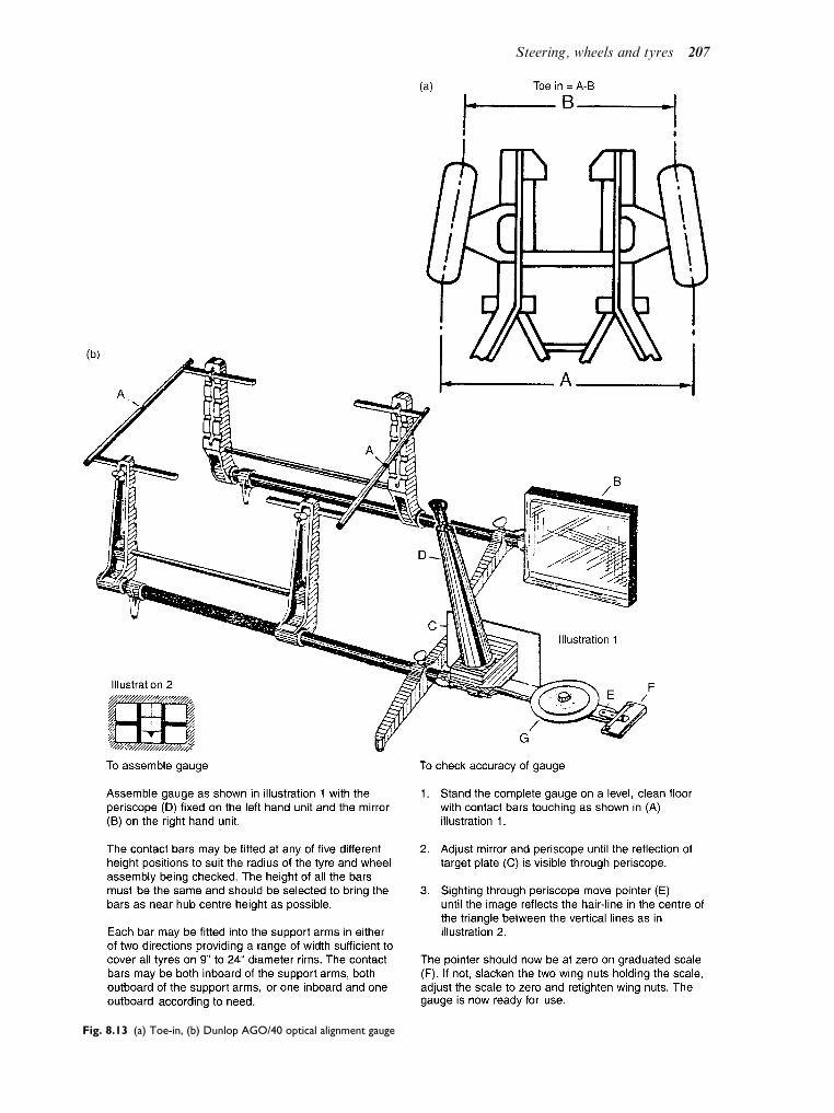
Fig. 8.13 (a) Toe-in, (b) Dunlop AGO/40 optical alignment gauge
Steering, wheels and tyres 207

are set to zero and are positioned on the wheels.The alignment is adjusted to give a reading onthe scale, which is then checked against themanufacturer’s specifications.
A more accurate method would be to usefour wheel alignment gauges. This would givethe mechanic more precise information as towhich wheel needs adjusting, whether the frontaxle lines up with the rear axle and if thevehicle suspension has been misaligned in anaccident.
Toe-out on turns
When turning a corner, the inner wheel turnsthrough a greater angle than the outer wheel.This difference in angles is called ‘toe-out onturns’ (Fig. 8.14). To check these angles thewheels are placed on turn tables and theouter wheel is turned on its axis through20. The inner wheel should now read a lar-ger angle (typically approximately 22). Thisis because it is rolling around a smallerradius.
When checking steering alignment such astoe-in or toe-out, a number of factors must beattended to, for example:
1. The vehicle must be on a level surface.2. The vehicle must be loaded to the makers
specification, such as may be the kerbsideunladen weight figure.
3. The tyres must be inflated to the correctpressure.
4. The front wheels should be in the straightahead position.
5. The vehicle should be rocked from side to sideto ease any stresses in the steering system.
6. Prior to checking the track, the vehicleshould be rolled forward by about a vehicle’slength in order to take up small amounts ofslack in the linkage.
If the track requires adjustment (toe-in or toe-out) it is important to ensure that the track rodsare maintained at the correct lengths, becausethis will affect the toe-out on turns. In the exam-ple shown in Fig. 8.14(b), the track rods are ofequal length. This may not always apply and
Fig. 8.14(a) Toe-out angle on turns. Inner wheel turns through a greater angle
X X
Track rod length
Fig. 8.14(b) Track rod length
208 A practical approach to motor vehicle engineering and maintenance

such details must be checked prior to makingany adjustments.
Learning tasks
1. Draw a simple diagram of the steering lay-
out to conform to the Ackermann principle.
Show the position of the front and rear
wheels, point of turn, approximate angles
of the front wheels and the position of the
track rod. Indicate on your diagram where
adjustments may be made.
2. Make a list of reasons why the steering
mechanism would require adjusting.
3. Draw up a workshop schedule that you
could use when checking a steering system
for signs of wear and serviceability.
4. What important safety factors would you
consider when working under a vehicle on
the steering system.
5. Name two steering faults that would cause
uneven tyre wear. How would these faults
be put right?
6. If a customer came into the workshop
complaining that his vehicle was ‘pulling
to one side’ when being driven in a
straight line, what would you suspect the
fault to be? Describe the tests you would
undertake to confirm your diagnosis.
7. Check the tracking on a vehicle using both
optical and four wheel alignment gauges.
Adjust the steering to the middle of the
limits set by the manufacturer.
8.8 Steering gearboxes
The steering gearbox is incorporated into thesteering mechanism for two main reasons:
. to change the rotary movement of the steer-ing wheel into the straight line movement ofthe drag link;
. to provide a gear reduction and therefore atorque increase, thus reducing the effortrequired by the driver at the steering wheel.
Quite a number of different types of steeringgearboxes have been used over the years, themost common ones being:
. worm and roller
. cam and peg
. recirculating ball (half nut)
. rack and pinion
The gearbox should have a degree of reversibil-ity to provide some driver ‘feel’ and at the sametime keep the transmission of road shocksthrough to the steering wheel to a minimum.The arrangement should be positive, i.e. itshould have a minimum amount of backlash.Most steering gearboxes are designed with thefollowing adjustments:
. end float of the steering column, usually byshims;
. end float of the rocker shaft, either by shimsor adjusting screw and lock nut;
. backlash between the gears – these can bemoved closer together, again by the use ofshims or adjusting screw and lock nut.
It is essential to keep the ‘backlash’ to a mini-mum to provide a positive operation of thesteering mechanism and to give directional sta-bility to the path of the vehicle. The componentsinside the gearbox are lubricated by gear oil andthe level plug serves as the topping up and levelposition for the oil.
Worm and roller
In this arrangement, shown in Fig. 8.15, theworm (in the shape of an hour glass) is formedon the inner steering column. Meshing with theworm is a roller which is attached to the rockershaft. As the steering is operated the rollerrotates in an arc about the rocker shaft givingthe minimum amount of backlash togetherwith a large gear reduction. This means thatfor a large number of turns on the steeringwheel there is a very small number of turnson the rocker shaft, with very little free play.Because of the specialized machining geometryand shape, the hour glass worm is really in theform of a cam rather than a gear. This is whythe arrangement is sometimes known as a cam-and-roller steering gearbox. It will mainly befound on LGVs as it provides a large gearreduction and can transmit heavy loads.
Cam and peg
In the cam and peg steering box a tapered peg isused in place of the roller. This engages witha special cam formed on the end of the innersteering column. The peg may be made torotate on needle roller bearings in the rockerarm to reduce friction as the steering column isrotated and the peg moves up and downthe cam.
Steering, wheels and tyres 209

Recirculating ball
In this arrangement the worm is in the form of athread machined on the inner steering column.A nut with steel ball bearings acting as the threadoperates inside the nut; as the worm rotates theballs reduce the friction to a minimum. In manycases a half nut is used and a transfer tubereturns the balls back to the other side of thenut. A peg on the nut locates in the rocker armwhich transfers a rocking motion to the rocker
shaft. In Fig. 8.16 a sector gear is used to transferthe movement to the rocker shaft.
Rack and pinion
This type, shown in Fig. 8.17, is now probablythe most common type in use on cars and lightvehicles. It has a rack which takes the place ofthe middle track rod and outer track rods(sometimes called tie rods) which connect tothe steering arms at the hub. The pinion is
Fig. 8.15 Worm and roller steering gearbox
Fig. 8.16 Recirculating ball rack and sector steering box
210 A practical approach to motor vehicle engineering and maintenance

mounted to the steering column by a universaljoint as often the steering column is not in linewith the input to the steering rack. This givesease of mounting and operation of the gearbox.
On each end of the rack is a ball joint to whichthe track rod is mounted; these are springloaded to allow for movement together withthe minimum of play in the joint. The systemis arranged so that in the event of an accidentthe column, because it is out of alignment (not asolid straight shaft) will tend to bend at thejoints. This helps to prevent the steering wheelfrom hitting the driver’s chest and causing ser-ious injury. A spring loaded rubbing pad (calleda slipper, Fig. 8.18) presses on the underside ofthe rack to reduce backlash to a minimum andalso to act as a damper absorbing road shocksthat are passed back through the steeringmechanism from the road surface.
Adjustment of the steering rack
The inner ball-joints of the outer track rod areadjusted to give the correct pre-load and thelocking ring of the ball-joint housing is tight-ened. In some cases it is locked to the rack bylocking pins which must be drilled out to dis-mantle the joint as shown in Fig. 8.19.
Shims are used to adjust the slipper/rubbingblock to give the correct torque on rotating thepinion (Fig. 8.20). Shims are also used to adjustthe bearings on the pinion. It is important thatthe correct data is obtained and used as thesemay vary from model to model.
Fig. 8.17 The complete layout of a rack and pinion steering
system showing the steering column, with universal joints (UJs)
Fig. 8.18 Exploded view of steering gear
Steering, wheels and tyres 211

Ball-joints
There are a number of requirements that mustbe fulfilled by steering ball-joints. These are:
. they must be free from excess movement(backlash) to give accurate control of thesteering over the service life of the vehicle;
. they must be able to accommodate theangular movement of the suspension andthe rotational movement of the steeringlevers;
. they must have some degree of damping onthe steering to give better control of thewobble of the wheels especially at lowspeeds;
. where possible eliminate the need for lubrica-tion at regular intervals – this is achievedthrough the use of good bearing materialsand sealing the bearing with a good-qualitygrease at manufacture.
Ball-joints that are used on modern cars do notneed lubricating as they are sealed for life,although on some medium to heavy vehiclesthey may require greasing at regular service
intervals. Track rod and ball-joint assembliesare shown in Fig. 8.21.
Learning tasks
1. What is the difference between angular
movement and rotational movement?
Which component in the steering mechan-
ism uses angular movement and which uses
rotational movement?
2. Using workshop manuals identify the
method for adjusting the types of steering
gearboxes identified in this chapter.
3. Dismantle each of the different types of
steering gearboxes. Fill in a job sheet for
each type. Note any faults or defects and
make recommendations for their service-
ability.
Fig. 8.19 (a) Drilling out tie rod inner ball-joint housing locking
pins, (b) unscrewing tie rod inner ball-joint housings
Fig. 8.20 (a) Checking tie rod articulation, (b) checking pinion
turning torque
212 A practical approach to motor vehicle engineering and maintenance

8.9 Front hub assemblies
Non-driving hubs
Figure 8.22 shows one type of front hub assem-bly used on a front engine rear wheel drivevehicle. As can be seen the hub rotates on apair of bearings that are either taper roller orangular-contact ball bearings. The inner bearingis usually slightly bigger in diameter than theouter, as this carries a larger part of the load.Various methods of adjustment are useddepending on the type of bearing and the loadto be carried. Some manufacturers specify atorque setting for the hub nut (usually wherea spacer or shims are positioned between thebearings); others provide a castellated nut thathas to be tightened to a specified torque andthen released before the split pin is located. Thehubs are lubricated with a grease that has a highmelting point; this is because the heat from thebrakes can be transferred to the hub, melt thegrease and cause it to leak out onto the brakes.A synthetic lip-type seal is fitted on the inside ofthe hub to prevent the grease escaping. It alsoprevents water, dust and dirt from entering intothe bearing. The arrangement in Fig. 8.23 isused mainly on larger vehicles where a beamaxle is fitted instead of independent suspension.
Driving hubs
Figure 8.24 shows one arrangement of huband drive shaft location using thrust-type
ball bearings, in this case a single bearingwith a double row of ball bearings. Whenthe nut is tensioned/tightened to the correcttorque it also adjusts the bearing to the cor-rect clearance.
On a front wheel drive vehicle the drive shaftpasses through the hub to engage with the flangethat drives the wheel. In this way the hubbecomes a carrier for the bearings (normallytaper roller – Fig. 8.25) which are mounted closetogether. Where angular-contact bearings areused they are of the double-row type which havea split inner ring, in this way large-diameter ballscan be used to give greater load carrying capa-cities; they also have the added advantage that
Fig. 8.21 Track rod end ball-joint assembly
Wheelhub
Suspensionvertical link
Wheelstud
Stubaxle
Fig. 8.22 Layout of non-driving hub assembly
Steering, wheels and tyres 213

Fig. 8.23 Axle-beam and stub-axle assembly
Fig. 8.24 Independent suspension front wheel drive stub-shaft and swivel-pin carrier assembly
214 A practical approach to motor vehicle engineering and maintenance

they require no adjustment and the torque settingfor the drive nut can be high to give good hub-to-shaft security.
8.10 Light vehicle wheels
Most cars use wheels with a well base rim ofthe types shown in Fig. 8.26. The standardtype of rim has the form shown in Fig.8.26(a). The rim has a slight taper and theinternal pressure in the tyre forces the bead ofthe tyre into tight frictional contact with thewheel. This tight contact is required so as tomaintain an air-tight seal and also to providethe grip that will transmit driving and brak-ing forces between the tyre and the wheel.The grip is dependent on the correct tyrepressure being maintained and, in the eventof a puncture, the tyre bead is likely to breakaway from the wheel rim. The double humprim shown in Fig. 8.26(b) is intended to pro-vide a more secure fixing for the tyre in thesense that, should a puncture occur, the beadof the tyre will be held in place by the humps
and this should provide a degree of control inthe event of a sudden, rapid puncture.
8.11 Types of car wheels
Most car wheels are fabricated from steel
pressings and their appearance is often alteredby the addition of an embellisher. Figures8.27 and 8.28 show a range of wheels andwheel trims as used on Ford Escort vehicles.When weight and possibly ‘sporty’ appear-ance is a consideration cast alloy wheels areused. The metals used are normally aluminium
alloy, or magnesium based alloy, and thewheels are constructed by casting. An alloywheel is shown in Fig. 8.27(e).
Figures 8.27(f) and 8.27(g) shows the differenttypes of wheel bolts and balance weights thatare required. The steel wheel uses a bolt with ataper under the head. This taper screws into acorresponding taper on the wheel and, when thecorrect torque is applied, the wheel is secured tothe vehicle hub. In order to prevent damage tothe alloy wheel its bolts are provided with a
Fig. 8.25 Layout of a driving hub arrangement
Steering, wheels and tyres 215

tapered washer. The taper on the washer sits inthe taper on the wheel and the bolt can betightened without ‘tearing’ the alloy of thewheel. Figure 8.27 also shows the two differenttypes of wheel balancing weights that arerequired. The obvious point to make here is thatthe steel wheel weight is not suitable for use onthe alloy wheel, and vice versa.
8.12 Wire wheels
These are wheels that are built up in a similarway to spoked bicycle wheels. Figure 8.29 showsa typical wire wheel. They are normally to befound on sports cars.
8.13 Wheel nut torque
In order to ensure that wheels are properlysecure it is advisable to use a torque wrenchfor the final tightening of the wheel nuts. Thisis shown in Fig. 8.30.
8.14 Tyres
Tyres play an important part in the steering,braking, traction, suspension and general con-trol of the vehicle. Two types of tyre construc-tion are in use. These are:
. cross-ply tyres
. radial-ply tyres
Fig. 8.26 Two types of wheel rim in common use
Fig. 8.27 A range of wheels
216 A practical approach to motor vehicle engineering and maintenance

The term ply refers to the layers of materialfrom which the tyre casing is constructed.
Cross-ply tyre
Figure 8.31 shows part of a cross-ply tyre.The plies are placed one upon the other andeach adjoining ply has the bias angle of thecords running in opposite directions. Theangle between the cords is approximately100 and the cords in each ply make an angleof approximately 40 with the tyre bead andwheel rim.
Radial-ply tyre
Figure 8.32 shows part of a radial-ply tyre. Theplies are constructed so that the cords of the tyrewall run at right angles to the tyre bead andwheel rim.
Cross-ply versus radial-ply tyre
Radial-ply tyres have a more flexible side walland this, together with the braced tread, ensuresthat a greater area of tread remains in contactwith the road when the vehicle is cornering.Figure 8.33 shows the difference betweencross-ply and radial-ply tyres when the vehicleis cornering. In effect, radial-ply tyres produce abetter grip.
It is this remarkable difference between theperformance of cross-ply and radial-ply tyres
Fig. 8.28 A range of wheel trims (embellishers)
Fig. 8.29 A wire (spoked) wheel
Fig. 8.30 Using a torque wrench for the final tightening
Steering, wheels and tyres 217

that leads to the rules about mixing of cross-plyand radial-ply tyres on a vehicle. Cross-plytyres on the front axle and radial-ply tyres onthe rear axle are the only combination that canbe used.
Tyre sizes
In general tyres have two size markings, oneindicating the width of the tyre and other givingthe diameter of the wheel rim on which the tyrefits. Thus, a 5.20 by 10 marking indicates a tyrewhich is normally 5.20 inches wide which fits a
10 inch diameter wheel rim. Radial-ply tyreshave a marking which gives the nominal widthin millimetres and a wheel rim diameter ininches; for example, a 145–14 tyre is a tyre witha nominal width of 145mm with a wheel rimdiameter of 14 inches.
Originally vehicle tyres were of circularcross-section and the width of the tyre sectionwas equal to its height. Over the years, devel-opments have led to a considerable change inthe shape of the tyre cross-section and it isnow common to see tyres where the width ofthe cross-section is greater than its height.These tyres are known as ‘low-profile’ tyres.Modern tyres now have an additional numberin the size; for example, 185/70–13. The 185 isthe tyre width in millimetres, the 13 is the rimdiameter in inches, and the 70 refers to thefact that the height of the tyre section is 70%
of the width. This 70% figure is also known asthe aspect ratio. The aspect ratio¼ (tyre sec-tion height/tyre section width) 100 per cent.Tyre size and other information is carried onthe side wall and Fig. 8.34 shows how theyappear on a typical tyre.
Load and speed ratings
The tyre load and speed ratings are thefigures and letters that refer to the maximumload and speed rating of a tyre. For example82S marked on a tyre means a load index of82 and a speed index of S. In this case the82 means a load capacity of 475 kg per tyre
Fig. 8.31 Cross-ply tyre construction
Fig. 8.32 Radial-ply tyre construction
Fig. 8.33 Cross-ply and radial-ply tyres under cornering
conditions
218 A practical approach to motor vehicle engineering and maintenance

and the S relates to a maximum speed of180 km/h or 113mph. One of the main pointsabout these markings is that they assist inensuring that only tyres of the correct speci-fication are fitted to a vehicle.
Tread wear indicators (TWI)
Tyres carry lateral ridges (bars) 1.6mm high inthe grooves between the treads at intervalsaround the tyre. The purpose of these tread wearindicators is to show when the tyre tread isreaching its minimum depth. Their position onthe tyre is marked by the letters TWI on the tyrewall, near the tread.
Tyre regulations
Tyres must be free from any defect whichmight cause damage to any person or to thesurface of the road. There are strict lawsabout worn tyres. They vary from time totime and it is important that you should beaware of current regulations. The followinglist is not complete but it does contain some
of the more widely known ones. It is illegal touse a tyre which:
. is not inflated to the correct pressure;
. does not have a tread depth of at least 1.6mmin the grooves of the tread pattern through-out a continuous band measuring at least 3/4of the breadth of tread and round the entirecircumference of the tyre;
. has a cut in excess of 25mm or 10% of thesection width of the tyre, whichever is thegreater, which is deep enough to reach the plyor the cord.
There are several other regulations and detailscan be found in tyre manufacturers’ data andConstruction and Use Regulations.
In addition to the rules about condition oftyres there are also strict regulations aboutmixing of cross-ply and radial-ply tyres. Forexample, it is illegal to have a mixture ofcross-ply and radial-ply tyres on the same axle.It is also illegal to have cross-ply tyres on therear axle of a vehicle that has radial-ply tyreson the front axle. If radial-ply and cross-plytyres are to be used on the same car, the ruleis radials on the rear.
Fig. 8.34 Typical tyre markings
Steering, wheels and tyres 219

8.15 Wheel and tyrebalance
Unbalanced wheels give rise to vibrations thataffect the steering and suspension, they can bedangerous and, if not rectified, can lead to wearand damage to components. Wheel balance canbe affected in many ways; for example, adamaged wheel or tyre caused by hittingthe kerb. Such damage must be rectified imme-diately and when the repair has been made thewheel and tyre assembly must be re-balanced.
A wheel balancer is a standard item of garageequipment. When new tyres are fitted, or ifwheels are being moved around on the vehicleto balance tyre wear, the wheel and tyre assemblyshould be checked and, if necessary, rebalanced.
8.16 Tyre maintenance
Tyre pressures
Tyre pressures have an effect on the steering,braking and general control of a vehicle and it isimportant to ensure that pressures are main-tained at the correct level for the conditions thatthe vehicle is operating in. In addition to affect-ing vehicle handling, tyre pressures have aneffect on the useful life of a tyre. The bar chartin Fig. 8.35 shows how various degrees of underinflation affect tyre life.
Inspecting tyres for wear anddamage
Tyres can be damaged in a number of ways,such as running over sharp objects, impact witha kerb, or collision with another vehicle. Tyredamage can also be caused by incorrect tyrepressures, badly adjusted steering track andaccidental damage that has affected steeringgeometry angles, such as castor and camber.
Tread wear patterns
Inflation pressures
In addition to checking tyre tread depth,the walls and casing of the tyre should be thor-oughly examined. Tread wear patterns are aguide to the probable cause of a problem.For example, under-inflated tyres produce morewear at the outer edges because the centre of thetread is pushed up into the tyre. Over-inflatedtyres wear at the centre of the tread because thatis where most of the load is carried.
Steering track, camber
Toe-in
Figure 8.36 shows an axle and wheel arrange-ment where the front wheels have toe-in. In thisdiagram, the outer edges of the tyre are referredto as the shoulders. If the amount of toe-in is
TYRE PRESSURES
100%
95%
75%
Effect of under-inflation on tyre life
% M
ileag
e
Cor
rect
pre
ssur
e
10%
Und
er-in
flate
d
20%
Und
er-in
flate
d
30%
Und
er-in
flate
d
40%
Und
er-in
flate
d
50%
Und
er-in
flate
d
67%
43%
22%
Fig. 8.35 Tyre wear and effect of pressures
220 A practical approach to motor vehicle engineering and maintenance

too great, the tyre tread will wear in a featherededge at the outer shoulder.
Toe-out
If the wheels have excessive toe-out, instead oftoe-in, the tyre tread will wear in a featherededge at the inner shoulder. (A feathered edge is athin layer of rubber that projects outwards awayfrom the tread.)
Camber
Excessive positive camber, where the wheel tiltsout at the top, causes the tyre to wear at theouter shoulder. Excessive negative cambercauses the tyre to wear at the inner shoulder.
Incorrect camber angle also affects the steer-ing, because the vehicle will pull in the directionof the wheel that has the greatest camber angle.
Learning tasks
1. Remove the wheels and tyres complete from a
vehicle. Check the following and record your
results on the job sheet for the customer:
(a) tread depth
(b) cuts and bulges
(c) tyre pressures
(d) signs of abnormal wear
Complete you report with a set of recom-
mendations.
2. Remove a tyre from a wheel, remove all the
balance weights, clean the rim and inspect
the tyre bead for damage. Check the inside
of the tyre for intrusions and signs of entry
of any foreign body such as a nail. Lubricate
the bead of the tyre and replace on the
wheel, inflate to the correct pressure, reba-
lance the wheel and refit to vehicle.
3. Produce a list of the current MOT require-
ments for wheels and tyres.
4. Describe a procedure that you have used
for fitting a new tyre.
5. Make a list of the precautions that must be
taken when removing a wheel in order to do
some work on the vehicle. Make special note
of the steps taken to prevent the vehicle from
moving and also the steps taken to ensure
that the vehicle cannot slip on the jack.
6. Examine a selection of wheel nuts. State
why the conical part of the nut, or set bolt,
is necessary. State why some vehicles, espe-
cially trucks, have left-hand threaded wheel
nuts, on the near side. (Left-hand side of the
vehicle when sitting in the driving seat).
7. Make a note of the type of wheel-balancing
machine that is used in your workshop.
Excessive shoulder wear/Feather edges
Front
Toe-in (positive): faster wear of outside shoulders with feather edgesoutside to inside.Toe-out (negative): faster wear of inside shoulders with feather edgesinside to outside
Fig. 8.36 Steering toe-in. (Reproduced with the kind permission of Goodyear Tyres.)
Positive Excessive shoulder wear
Positive camber (upper wheel part tilted outwards):faster wear of outside shoulder.Negative camber (upper wheel end tilted inwards):faster wear of inside shoulder.
Fig. 8.37 Steering camber angle. (Reproduced with the kind
permission of Goodyear Tyres.)
Steering, wheels and tyres 221

State the safety precautions that must be
taken when using it and make a list of the
major points that you need to know about
when balancing a wheel and tyre assembly.
8. State the type of tyre-thread depth gauge that
you use. Describe how to use it and state the
minimum legal tread depth in the UK.
9. Examine a number of tyres and locate the
tyre-wear indicator bars. State which mark
on the tyre wall helps you to locate these
wear indicators.
Practical assignment –steering worksheet
Introduction
After this practical exercise you should be able to:
. check and adjust steering alignment
. assess for wear in steering components
. remove and replace track rod ends
. check tyres for misalignment
. make a written report on your findings
Tools and equipment
. vehicle with appropriate steering mechanism
. appropriate workshop manual
. selection of tools and specialist equipment, e.g.
alignment gauges. vehicle lift or jacks and stands
Activity
1. Inspect the steering for wear and security, e.g.
(a) uneven wear on tyres
(b) play in track-rod ends, steering rack and
column
(c) play in wheel bearings
(d) security of shock absorbers/dampers, check
for leaks
(e) wear/play in suspension joints
(f ) security/wear in anti-roll bar mountings
2. Remove and refit at least one track rod end.
3. Using appropriate equipment check tracking of
vehicle’s steered wheels.
4. Check steering angles – castor, camber, king pin
inclination, toe-out on turns.
5. Make any adjustments necessary.
6. Investigate where possible the following types
of steering gearboxes:
(a) worm and roller
(b) cam and peg
(c) recirculating ball
(d) rack and pinion
7. Make any adjustments on the above types of steer-
ing gearboxes after stripping and rebuilding them.
8. Produce a report on the condition of the steer-
ing including the gearboxes, indicating wear and
serviceability.
9. State the meaning of the following terms:
(a) tracking
(b) toe-out on turns
(c) steering angles – castor, camber, KPI, Ack-
erman angle
(d) roll radius
Checklist
Vehicle
Exercise Datestarted
Datefinished
Serviceable Unserviceable
Rack and pinionRecirculating ballWorm and pegWorm androller (hour glass)CastorCamberKPIToe-out on turnsOptical alignment gaugeFour wheel aignmentBody alignment
Student’s signature
Supervisor’s signature
222 A practical approach to motor vehicle engineering and maintenance

Self assessment questions
1. Figure 8.38 shows six examples of tyre wear
problems. State a probable cause for each
case.
2. Tread wear indicators on tyres:
(a) are located in the grooves between the tyre
treads
(b) only become visible when the tread is worn
to the legal limit
(c) have their positions indicated by an arrow
on the wheel rim
(d) indicate that the tyre is completely legal
3. A car is to be fitted with two radial ply tyres and
two cross ply tyres. In this case:
(a) both radial ply tyres should be fitted to one
side of the vehicle
(b) the radial ply tyres should be fitted to the
rear wheels
(c) the tyres should be mixed diagonally
(d) it does not matter where they are fitted
4. In a tyre size of 185/70 – 13, the aspect ratio is:
(a) 185
(b) 70%
(c) 13
(d) 198
5. In a steering system that uses a cam and peg
steering box, the drop arm:
(a) controls back lash in the mechanism
(b) transmits a pull-push motion to the drag link
(c) connects the steering arms to the stub axle
(d) transmits steering wheel motion to the
cam
6. When checking the steering geometry on a
certain vehicle, it is found that the camber angle
on the nearside is 2.6 degrees and on the offside
it is only 1.2 degrees. This difference:
(a) may have caused the vehicle to pull to the
right
(b) may have caused the left front tyre to wear
on the inside edge
(c) may have caused the vehicle to pull to the left
(d) is not significant
7. With centre point steering:
(a) the centre of tyre contact meets the road
surface at the same spot as the centre line
of the king pin
(b) the vehicle’s centre of turn is on a line that
passes through the centre of gravity of the
vehicle
(c) the steering gear box in the centre of the
vehicle
(d) no king pin inclination or camber angle is
required
Learning tasks (wheels and tyres)
1. Describe a procedure that you have used
for fitting a new tyre.
2. Make a list of the precautions that must be
taking when removing a wheel in order to do
some work on the vehicle. Make special note
of the steps taken to prevent the vehicle from
moving and also the steps taken to ensure
that the vehicle cannot slip on the jack.
3. Examine a selection of wheel nuts. State
why the conical part of the nut, or set bolt,
is necessary.
State why some vehicles, especially trucks,
have left-hand threaded wheel nuts on the
near side. (Left-hand side of the vehicle
when sitting in the driving seat.)
4. Make a note of the type of wheel balancing
machine that is used in your workshop.
State the safety precautions that must be
taken when using it and make a list of the
major points that you need to know about
when balancing a wheel and tyre assembly.
5. State the type of tyre tread depth gauge that
you use. Describe how to use it and state
the minimum legal tread depth in the UK.
6. Examine a number of tyres and locate the
Tyre Wear Indicator bars. State which mark
on the tyre wall helps you to locate these
wear indicators.
Rapid wearat shoulders
Rapid wearat centre
Crackedtreads
Featherededge
Baldspots
a b c
Wear onone side
d e f
Fig. 8.38 Tyre tread wear patterns
Steering, wheels and tyres 223

9Electrical and electronic principles
Topics covered in thischapter
Principles of magnetism and electricity
Introductory electronics
Computer controlled systems
Networking and CAN
Multiplexing
Meters
9.1 Electricity andmagnetism
Permaent magnets
Permanent magnets are found in nature.Magnetite, which is also known as lodestone,is naturally magnetic and ancient mariners usedit as an aid to navigation. Modern permanentmagnets are made from alloys. One particularpermanent (hard) magnetic material named‘alnico’, is an alloy of iron, aluminium, nickel,cobalt and a small amount of copper. The mag-netism that it contains arises from the structureof the atoms of the metals that are alloyedtogether.
Magnetic force is a natural phenomenon.To deal with magnetism, rules about its beha-viour have been established. The rules thatare important to our study are related to the
behaviour of magnets and the main rules thatconcern us are:
. Magnets have North and South poles;
. Magnets have magnetic fields;
. Magnetic fields are made up from lines ofmagnetic force;
. Magnetic fields flow from North to South.
If two bar magnets are placed close to eachother, so that the north pole of one is close tothe south pole of the other, the magnets will bedrawn together. If the north pole of one magnetis placed next to the north pole of the other, themagnets will be pushed apart. This tells us thatlike poles repel each other and unlike polesattract each other.
Electromagnetism
The magnetic effect of an electriccurrent
Figure 9.2 shows how a circular magnetic field isset up around a wire (conductor) which is carry-ing electric current.
Direction of the magnetic field due to anelectric current in a straight conductor.
Fig. 9.1 Attraction and repulsion of magnets Fig. 9.2 Magnetic field around a straight conductor

Think of screwing a right-hand threaded boltinto a nut, or a screw into a piece of wood. Thescrew is rotated clockwise (this corresponds tothe direction, north to south, of the magneticfield). The screw enters into the wood and thiscorresponds to the direction of the electric cur-rent in the conductor. The field runs in a clock-wise direction and the current flows in towardsthe wood, as shown in Fig. 9.3.
This leads to a convention for representingcurrent flowing into a conductor and currentflowing out. At the end of the conductor, wherecurrent is flowing into the wire, aþ is placed, thisrepresenting an arrow head. At the opposite endof the wire, where current is flowing out, a dot isplaced, this representing the tip of the arrow.
Magnetic field caused by a coil of wire
When a conductor (wire) is made into a coil, themagnetic field created is of the form shown inFig. 9.5; a coil such as this is the basis of asolenoid.
9.2 Electromagneticinduction
Figure 9.6 shows a length of wire that has avoltmeter connected to its ends. The smallarrows pointing from the North pole to theSouth pole of the magnet, represent lines ofmagnetic force (flux) that make a magnetic field.
The arrow in the wire (conductor) shows thedirection of current flow and the larger arrow,
with the curved tail, shows the direction inwhich the wire is being moved. Movement ofthe wire through the magnetic field, so that itcuts across the lines of magnetic force, causes anelectromotive force EMF (voltage) to be pro-duced in the wire. In Fig. 9.6(a), where the wireis being moved upwards, the electric currentflows in towards the page. In Fig. 9.6(b), thedirection of motion of the wire is downwards,across the lines of magnetic force, and the cur-rent in the wire is in the opposite direction.Current is also produced in the wire if the mag-net is moved up and down while the wire is heldstationary. Mechanical energy is being con-verted into electrical energy, and this is theprinciple that is used in generators, such asalternators and dynamoes.
9.3 The electric motoreffect
If the length of wire shown in Fig. 9.6(a) is madeinto a loop, as shown in Fig. 9.7, and electriccurrent is fed into the loop, opposing magneticfields are set up.
In Fig. 9.7, the current is fed into the loop viabrushes and a split ring. This split ring is a
Fig. 9.3 Direction of magnetic field
Fig. 9.4 Convention for representing current flow and magnetic
field
Fig. 9.5 Magnetic field of a coil
Electrical and electronic principles 225

simple commutator. One half of the split ring isconnected to one end of the loop and the otherhalf is connected to the other end. The effect ofthis is that the current in the loop flows in onedirection. The coil of wire that is mounted onthe pole pieces, marked N and S, creates themagnetic field. These opposing fields createforces, which force (push) against each other,as shown in Fig. 9.8, and cause the loop torotate.
In Fig. 9.8 the ends of the loop are marked Aand B. B is the end that the current is flowinginto, and A is the end of the loop where thecurrent is leaving the loop.
By these processes, electrical energy is con-verted into mechanical energy and it is the prin-ciple of operation of electric motors, such as thestarter motor. Just to convince yourself, tryusing Fleming’s rule to work out the directionof the current, the field and the motion.
9.4 Fleming’s rule
Consider the thumb and first two fingers oneach hand. Hold them in the manner shown inFig. 9.9.
. Motion This is represented by the directionthat the thumb (M for motion) is pointing.Fig. 9.6 Current flow, magnetic field and motion
Fig. 9.7 Current flowing through the loop
Fig. 9.8 Opposing magnetic fields
Fig. 9.9 Fleming’s rule
226 A practical approach to motor vehicle engineering and maintenance

. Field The direction (North to South) of themagnetic field is represented by the first finger(F for field).
. Current Think of the hard c in second. Thesecond finger represents the direction of theelectric current.
An aid to memory
We think that it is helpful for vehicle techniciansto think of the MG car badge. If you imagineyourself standing in front of an MG, lookingtowards the front of the vehicle, the badge willpresent you with an M on your left and a G onyour right. So you can remember M forMOTORS andG for GENERATORS, left-handrule for motors, right-hand rule for generators.
9.5 Electrical circuitprinciples
Materials can usefully be divided into threecategories:
1. conductors2. semi-conductors3. insulators
Electrical conductance andresistance
The ability of a material to conduct electricity isknown as its conductivity. The opposite (inverse)of conductivity is resistivity.
Conductors
Examples of commonly used conductors arecopper, aluminium and, in electronics, silverand gold.
Semi-conductors
Materials such as silicon do not have good insu-lating properties, and are not good conductors.These materials are known as semi-conductors.
Silicon is a semi-conductor material that iswidely used in electronics and its conductivitycan be varied by doping.
Insulators
These are materials where large electrical potential(applied voltage) causes only very small current toflow. Rubber, most plastics and ceramics, such asporcelain, are commonly used insulators.
Temperature coefficient ofresistance
The resistance of most materials changes withtemperature. In the case of conductors, the resis-tance of the material increases as the temperatureincreases. The relationship between resistanceand temperature is affected by a factor knownas the temperature coefficient of resistance.
Negative temperature coefficientof resistance (NTC)
When the temperature of a semi-conductor rises,the resistance falls and is said to have a negativetemperature coefficient. A material with a nega-tive temperature coefficient is used in the thermis-tor sensor that detects engine coolant temperature.
9.6 Electric circuits
Electricity will only perform its task if it hascircuits to flow through. It is, therefore, neces-sary to have some knowledge of electric circuits.To begin with, we need to consider three elec-trical units. These are:
(i) The voltThis is the unit of electrical pressure.(ii) The ampere, or amp This is the unit of
electric current.(iii) The ohm This is the unit of electrical
resistance.
Ohm’s law
Voltage, current and resistance are related byOhm’s law. Ohm’s law is often taken to meanthat if a voltage is applied to a circuit that con-tains resistance, the current that flows in the cir-cuit will be proportional to the voltage, providedthat the temperature remains constant. Ohm’slaw is normally expressed mathematically as
VOLTAGE ¼ CURRENTRESISTANCE
The symbol V is used for volts. I ¼ currentin amperes. R ¼ resistance in Ohms: Ohm’s lawis expressed algebraically as
V ¼ IR
A common practice in teaching is to buildcircuits and by using low voltage (2 volts), directcurrent supplies and resistors of known value, totake meter readings of current and voltage.These readings are noted down and compared
Electrical and electronic principles 227

with those that are calculated by using Ohm’slaw. The examples shown here should make thepoint adequately. If you are a complete beginneryou will need to take a short course in principlesof electricity, preferably a course that offersplenty of practical work with circuits.
An Ohm’s law circuit
Figure 9.10 shows a circuit that may be used tocheck the relation between voltage, current andresistance. The graph obtained by varying thevoltage and measuring the current, for a givenresistance, shows that V ¼ I R.
9.7 Circuit testing andmeters
Electrical systems are designed so that each ele-ment of a circuit will have a known resistancevalue. These resistance values must be maintainedthroughout the life of the system. The operationof vehicle electrical/electronic systems can beupset if resistance values, for any part of a circuit,are incorrect. Checking of electrical resistance invehicle circuits is therefore an important part of a
vehicle technician’s skill. Whilst it is possible toperform resistance checks on vehicle circuits with-out a great deal of background knowledge, it isbeneficial to have some understanding of princi-ples because a little deeper understanding oftenassists technicians to work out reasons why somedevice is not working correctly.
Meters
The instrument panel on most vehicles carries agreat deal of driver information, for example,vehicle speed (speedometer), coolant temperature,oil pressure and so on. Meters are also used forfault diagnosis and it is useful to have an insightinto the operating principles of two test metersas this will give an understanding that shouldassist in understanding how other meters work.Figure 9.11 shows twometers that can be used for
Fig. 9.10 Demonstrating Ohm’s law
Fig. 9.11 Two types of test meters (a) moving coil, (b) digital
228 A practical approach to motor vehicle engineering and maintenance

circuit testing. The one on the left is a moving coilmeter and the one the right is a digital meter.
A moving coil meter
The moving coil meter takes the sample currentinto the moving coil. This causes the moving coilmagnetic field to react with the field of the perma-nent magnet. Partial rotation of the coil and itspointer then occurs, against the force of the controlspring. The amount of movement is related to thesize of the variable being measured, for example,volts, amperes and ohms. A good-quality movingcoil meter with a resistance of 20 000 ohms per voltis suitable for most circuit testing on vehicles.
A digital meter
A digital meter samples the variable being mea-sured, such as volts, amperes and ohms and pro-cesses them in the electronic circuits of the meter.The resulting reading is displayed on a liquid crys-tal (LCD) panel. Digital meters have a high inputimpedance (resistance), which makes them suita-ble for diagnostic checks on electronic systems.
9.8 Electronics
Electronics is a branchof electrical engineering andit is concernedwith the ‘the science and technology
of the conduction of electricity in a vacuum, a gasor a semi-conductor’. It is the semi-conductor thatconcerns us most, at this stage, so it is necessary toexplain what the term means.
Semi-conductors
Metals such as copper, aluminium and gold aregood conductors of electricity and other materi-als like rubber and PVC, are bad conductorsand are known as insulators. Materials such assilicon and germanium have conductivity whichlies between that of good conductors and insu-lators. These materials are semi-conductors.Semi-conductors allow an electric current toflow only under certain circumstances.
Doping
Pure silicon, when treated (doped) with sub-stances such as aluminium or gallium, is widelyused in the manufacture of electronic compo-nents. The doping agents, which are added in tinyconcentrations (probably less than one part permillion) cause the silicon to become more con-ductive. The doping agents are divided into twogroups, called 1) acceptors and 2) donors.
Typical acceptors are boron, gallium, indiumand aluminium. When an acceptor is added tothe silicon it forms p-type silicon. The acceptorforms holes, which behave like a mobile positivecharge, and so this silicon is called p-type.
Typical donors are arsenic, phosphorous andantimony. When a donor is added to the silicon,it forms n-type silicon. It is called n-typebecause electric currents with in it are carriedby (negatively charged) electrons.
The p-n junction
A p-n junction is a junction, between p-typesilicon and n-type silicon, within a single crystal.If wires are attached to the material on eithersided of the p-n junction, it is found that currentwill pass through the device in one direction, butvery little in the opposite direction. Such adevice is a junction rectifier, which is commonlyknown as a junction diode, or just a ‘diode’.
Thus we have a device that acts like a one-way valve, which will pass current in one direc-tion but not the other.
Figure 9.13 shows a representation of a p-njunction, in silicon, connected to a source ofelectricity. When it is connected in the wayshown, with the positive battery terminal con-nected to the p-type material, the junction is
Fig. 9.12 Detail of the test meters (a) moving coil, (b) digital
voltmeter circuit
Electrical and electronic principles 229

said to be forward biased. When the forwardvoltage reaches approximately 0.7 volts, a con-tinuous current will flow in the forward direc-tion. Diodes are made for many applications,such as rectification of a.c. to d.c., switchingcircuits and so on. Figure 9.14 shows a diodein a metallic heat sink. The second terminal ofthe diode is formed from the metal case intowhich it is built and the heat sink conducts heataway from the diode.
Figure 9.15 shows the symbol for a diode. Thearrow indicates the direction in which currentwill flow. Diodes are used in circuits to permitcurrent flow in one direction only. A commonuse of a diode is in the conversion (rectifying) ofalternating current (a.c.) to direct current (d.c.),as shown in the section on alternators.
Testing a junction diode
The fact that a diode conducts freely in the for-ward direction and virtually not at all in thereverse direction, means that an ohm-meter canbe used to check for correct operation of the diode.
Other types of diodes
In addition to the junction diode, extensive useis made of other types of diodes. We shall have abrief look at two of these, namely the Zenerdiode and a light emitting diode (LED).
Zener diode
The Zener effect occurs when a heavily dopeddiode is reverse biassed. The Zener effect per-mits a low reverse voltage to produce break-down and the diode conducts in the reversedirection. Diodes that are made to work in thisway are called ‘Zener’ diodes. The Zener diodemay be thought of as a voltage conscious switchand it is often used as a voltage reference indevices such as voltage regulators.
Figure 9.17 shows a simple circuit with a Zenerdiode in series with a bulb. If the potential divi-der slider is placed in the zero volts position andthen moved towards the right, the Zener diodewill conduct when the Zener voltage is reached
Fig. 9.13 A p-n junction
Fig. 9.14 A diode
Fig. 9.15 Circuit symbol for a diode
Fig. 9.16 Diode test using Avo 2002 (Thorn EMI)
230 A practical approach to motor vehicle engineering and maintenance

and the bulb will light up. Note the direction ofcurrent flow through the Zener diode.
A light emitting diode (LED)
Silicon is an opaque material which blocks thepassage of light and the energy which derivesfrom the action of the diode is given off asheat. LEDs are different because they use othersemi-conductor materials, such as gallium,arsenic and phosphorous and the energy deriv-ing from their operation is given out as light.The material from which the LED is madedetermines the colour of the light given out.
It may be considered that the LED is a semi-conductor device which gives out light whencurrent flows through it. LEDs are used as indi-cator lights and for fault indicator codes onsome electronic systems.
Transistors
The transistor is another basic building block ofelectronic circuits. It may be thought of as two p-njunction diodes, connected back to back, as shownin Fig. 9.20 (this makes a bi-polar transistor).Transistors are used as switches or current/voltageamplifiers, and in many other applications.
Transistors have 3 connections, named asfollows:
. base – (b)
. collector – (c)
. emitter – (e)
Transistors are non-conductive until a verysmall current flows through the base/emittercircuit. This very small current, in the base/emitter circuit, ‘turns on’ the collector/emittercircuit and permits a larger current to flowthrough the collector/emitter circuit. When
Fig. 9.17 Action of the Zener diode (a) low voltage – no light, (b) higher voltage – lamp lights
Fig. 9.18 An LED and its circuit symbol
Fig. 9.19 LEDs for fault code display
Electrical and electronic principles 231

the base/emitter current is switched off thecollector emitter immediately ceases to con-duct and the transistor is effectively switchedoff. This happens in a fraction of a second (afew nano-seconds, usually) and makes thetransistor suitable for high-speed switchingoperations, as required in many vehicle appli-cations. The use of switching transistors iscovered in the chapter on ignition systems.
Integrated circuits (I/Cs)
Many diodes, resistors and transistors can bemade on a single piece of silicon (a chip). Whenthese are connected together in specific ways, tomake circuits on one piece of silicon, the resultingdevice is known as an integrated circuit (I/C).When a small number of diodes, transistorsand resistors are connected together (about 12)the result is called small-scale integration (SSI).When the number is greater than 100, it is called
large-scale integration (LSI). From the outside,an I/C looks like Fig. 9.22.
The ‘legs’ along the sides are metal tagswhich are used to connect the I/C to othercomponents. The number of tags is related tothe complexity of the I/C. When I/CS arepackaged as shown, they are known as DILtype, which means that the ‘legs’ are dualin line. Figure 9.23 shows an I/C built intoan ECU.
Field effect transistors (FETs)
This type of transistor is faster in operation anduses less power than a bi-polar transistor. Theyare used in integrated circuits and many otherapplications.
The FET shown in Fig. 9.24 is a CMOSdevice. CMOS stands for complementary, metal,oxide, semi-conductor. These words relate to theway that the transistor works and the variouslayers of material that make up the transistor.
When the gate voltage reaches a certain level,the channel becomes conductive and an electri-cal connection is made between the source andthe drain. The source and drain can thus beconnected and disconnected electrically, by theapplication and removal of the gate voltage.There are several different types of FETs andthe circuit symbol shown in Fig. 9.25 is typicalof the type of symbol used to represent them oncircuit diagrams.
9.9 Logic devices
A common use of transistors is to make logicdevices, such as the NOR gate.
Figure 9.26 shows how a ‘logic’ gate is builtup from an arrangement of resistors and atransistor. There are three inputs, A, B and C.If one or more of these inputs is high (logic 1),the output will be low (logic 0). The output isshown as Aþ Bþ C with a line or bar over thetop; the þ sign means OR. Thus, the Aþ Bþ C
Fig. 9.20 Two p-n junctions back to back
Fig. 9.21 A transistor
I/C
Fig. 9.22 A typical I/C
232 A practical approach to motor vehicle engineering and maintenance

with the line abovemeans ‘notAorBorC’ (NOR :NOT OR).
The base resistors Rb have a value that ensuresthat the base current, even when only one input ishigh (logic 1), will drive the transistor intosaturation to make the output low (logic 0).(RTL stands for resistor transistor logic).
Truth tables
Logic circuits operate on the basis of Booleanlogic and terms such as NOT, NOR, NAND,etc. derive from Boolean algebra. This need notconcern us here but it is necessary to know thatthe input–output behaviour of logic devices isexpressed in the form of a ‘truth table’.
The truth table for the NOR gate is given inFig. 9.27.
Fig. 9.23 An I/C in an ECU
Fig. 9.24 A CMOS field effect transistor
Fig. 9.25 Circuit symbol for FET
Fig. 9.26 The RTL NOR gate
Fig. 9.27 NOR gate symbol and truth table
Electrical and electronic principles 233

In computing and control systems, a systemknown as TTL (transistor to transistor logic) isused. In TTL logic 0 is a voltage between 0 and0.8 volts. Logic 1 is a voltage between 2.0 and5.0 volts.
In the NOR truth table, when the inputs A andB are both 0 the gate output, C, is 1. The other3 input combinations each gives an output C ¼ 1.
A range of other commonly used logic gatesand their truth tables is given in Fig. 9.28.
Fig. 9.28 A table of logic gates and symbols
234 A practical approach to motor vehicle engineering and maintenance

9.10 Computer (ECM)controlled systems
Whilst vehicle computers (ECMs) are not madeto be repaired in garage workshops, there arecertain factors that require technicians to havean appreciation of computer technology. Forexample, diagnostic trouble codes (DTCs) arean important part of fault finding and DTCs arestored in computer memory. The means bywhich these codes are read out varies from vehi-cle to vehicle and it is helpful for technicians tounderstand why a procedure for reading outDTCs on one vehicle may not work on anothervehicle. It is also the case that technicians insome main dealer workshops are required touse special equipment to amend the computeroperating program. Increasingly, use is beingmade of ‘freeze frame’ data. This is ‘live’ datathat is captured while the system is in operationand it is useful in helping to determine thecauses of a system fault. Whilst these operationsare normally performed through the use of ‘userfriendly’ diagnostic equipment, it is still the casethat an understanding of what can and whatcannot be done via the ECM is useful.
The fundamental parts of acomputer
Figure 9.29 shows the general form of a com-puter that consists of the following parts:
1. A central processing unit (CPU)2. Input and output devices (I/O)
3. Memory4. A program5. A clock for timing purposes.
Data processing is one of the main functionsthat computers perform. Data, in computerterms, is the representation of facts or ideas ina special way that allows it to be used by thecomputer. In the case of digital computers, thisusually means binary data where numbers andletters are represented by codes made up from 0sand 1s. The input and output interfaces enablethe computer to read inputs and to make therequired outputs. Processing is the manipula-tion and movement of data and this is con-trolled by the clock. Memory is required tohold the main operating program and to tem-porarily hold data while it is being worked on.
Computer memory
Read only memory (ROM)
The ROM is the place where the operating pro-gram for the computer is placed. It consists ofan electronic circuit which gives certain outputsfor predetermined input values. ROMs havelarge storage capacity.
Read and write, or random accessmemory (RAM)
The RAM is the place where data is heldtemporarily while it is being worked on by theprocessing unit. Placing data in memory is‘writing’, and the process of using this data iscalled ‘reading’.
Memory
Centralprocessing
unit(CPU)
Clock
Crystal
Fuel injectionOutputsInputs
EGRvalve
Speed sensor
Air flow sensor
Temperaturesensor
Program
Fig. 9.29 The basic components of a computer system
Electrical and electronic principles 235

Keep alive memory (KAM)
The term keep alive memory (KAM) refers to thesystems where the ECM has a permanent fusedsupply of electricity. Here the fault codes arepreserved, but only while there is battery power.Figure 9.30 shows a circuit for a KAM system.
Electrically erasable programmable read onlymemories (EEPROMs) are sometimes used forthe storage of fault codes and other data relat-ing to events connected with the vehicle system.This type of memory is sustained even whenpower is removed.
The clock
The clock is an electronic circuit that utilises thepiezo-electric effect of a quartz crystal to pro-duce accurately timed electrical pulses that areuse to control the actions of the computer. Clockspeeds are measured in the number of electricalpulses generated in one second. One pulse persecond is 1 Hertz and most computer clocksoperate in millions of pulses per second. Onemillion pulses per second is 1 mega Hertz (1Mz).
A practical automotive computersystem
Figure 9.31 shows a computer controlled trans-mission system.
At the heart of the system is an electronicmodule, or ECU. This particular module is aself-contained computer which is also known asa microcontroller. Microcontrollers are avail-able in many sizes, for example 4, 8, 16 and 32bit which refers to the length of the binary codewords that they work on. The microcontroller inthis transmission is an 8 bit one.Fig. 9.30 A KAM system
Fig. 9.31 A computer controlled transmission system
236 A practical approach to motor vehicle engineering and maintenance

Figure 9.32 shows some of the internal detailof the computer and the following descriptiongives an insight into the way that it operates:
1. The microcomputer This is an 8 bit micro-controller. In computer language a bit is a 0or a 1. The 0 normally represents zero, orlow voltage, and the 1 normally represents ahigher voltage, probably 1.9 volts. Themicrocontroller integrated circuit (chip) hasa ROM capacity of 2 049 bytes. There are 8bits to one byte. There is also a RAM thatholds 64 bytes.The microcontroller also has an on-chip
capacity to convert 4 analogue inputs into9 bit digital codes.
2. The power supply is a circuit that takes itssupply from the vehicle battery. It thenprovides a regulated d.c. supply of 5 voltsto the microcontroller and this is its workingvoltage. The power supply also includesprotection against over voltage and lowvoltage. The low voltage protection is
required if battery voltage is low and oftentakes the form of a capacitor.
3. The clock circuit In this particular applica-tion, the clock operates at 4MHz. The clockcontrols the actions of the computer, such ascounting sensor pulses to determine speedand timing the output pulses to the electro-valves so that gear changes take placesmoothly and at the required time.
4. The input interface The input interface at 4)contains the electronic circuits that providethe electrical power for the sensors andswitches that are connected to it. Some ofthese inputs are in an electrical form (analo-gue) that cannot be read directly into thecomputer and these inputs must be convertedinto computer (digital) form at the interface.
5. The output (power) interface The power driverat 5) consists of power transistors that areswitched electronically to operate electro-valves that operate the gear change hydraulics.
6. Feedback At 6) on the diagram the inscriptionreads ‘Reading electrical state’. This means
Fig. 9.32 Internal details of the computer
Electrical and electronic principles 237

that the computer is being made aware of thepositions (on or off ) of the electro-valves.
7. The watchdog The watch dog circuit at 7) is atimer circuit that prevents the computer fromgoing into an endless loop that can some-times happen if false readings occur.
8. The diagnostic interface The diagnostic inter-face at 9) is a circuit that causes a warninglamp to be illuminated in case of a systemmalfunction and it can also be used to con-nect to the diagnostic kit.
Fault codes
When a microcontroller (computer) is control-ling the operation of an automotive system,such as engine management, it is constantlytaking readings from a range of sensors. Thesesensor readings are compared with readingsheld in the operating program and if the sensorreading accords with the program value in theROM, the microcontroller will make decisionsabout the required output to actuators, such asinjectors. If the sensor reading is not withinlimits it will be read again and if it continuesto be ‘out of limits’, a fault code will be stored ina section of RAM. It is also probable that thedesigner will have written the main program sothat the microcontroller will cause the system tooperate on different criteria until a repair can bemade, or until the fault has cleared. The faultcodes, or diagnostic trouble codes DTCs as theyare sometimes called, are of great importance toservice technicians and the procedures for gain-ing access to them need to be understood. Itshould be clear that, if they are held in ordinaryRAM, they will be erased when the ECM poweris removed and that is why various methods ofpreserving them, such as KAMs andEEPROMS, are used.
Adaptive operating strategy ofthe ECM
During the normal lifetime of a vehicle, oftencompression pressures and other operating fac-tors change. To minimise the effect of thesechanges, many computer controlled systemsare programmed to generate new settings thatare used as references by the computer when it iscontrolling the system. These new (learned) set-tings are stored in a section of memory, nor-mally RAM. This means that such ‘temporary’operating settings can be lost if electrical power
is removed from the ECM. In general, when apart is replaced or the electrical power isremoved for some reason, the vehicle must betest driven for a specified period in order topermit the ECM to ‘learn’ the new settings. Itis always necessary to refer to the repair instruc-tions for the vehicle in question, because proce-dures do vary from vehicle to vehicle.
9.11 Networking and bussystems
When a number of computer controlled sys-tems on a vehicle are required to communicatewith each other, as happens with cruise con-trol, traction control, diagnostics and othersystems, the computers are connected to eachother for communication purposes. Linkingcomputers together, for communications pur-poses, is called networking and the lines (wires)that are used for this purpose are known asbuses. The bus systems that are commonlyused on vehicles are described in the followingsections.
CAN Controller Area Network
CAN is the commercial name (Robert Bosch) ofa system that is used to provide a means bywhich different computer controlled systemson a vehicle can communicate with each other.
Communication between systems is necessaryin cases such as traction control systems, wherethe purpose of the system is to improve thevehicle’s performance by eliminating wheel spin.Because the engine computer, the ABS com-puter and the instrument panel computer mustcommunicate (effectively talk to each other) athigh speed (in real time) they are linkedtogether, for communication purposes, by a pairof wires. These wires form a communicationssystem known as a bus – in this case a CANbus. The communication buses carry messagesonly and operate at low electrical current values.The electrical power that operates devices suchas ABS actuators, fuel valves, etc., is supplied byseparate cables.
CAN details
The speed at which computers communicatealong the bus is known as the baud rate. Adata transmission rate of one binary bit (0 or 1)
238 A practical approach to motor vehicle engineering and maintenance

per second is one baud. The CAN Systemsused on vehicles operate in real time, whichis taken to mean up to 500kbaud. 1 kbaud¼ 1 000 bits=second.
CAN is a two wire system and the wires aretwisted together in order to reduce electro-magnetic interference that may corrupt the datathat is being transmitted. The wires are knownas CAN H and CAN L and the voltages usedfor high speed (high baud rate) systems are3.5 volts, 2.5 volts and 1.5 volts.
The computing messages that are trans-mitted in serial form, ‘one bit at a time’ alongthe CAN bus are constructed to prevent errorsoccurring. The way in which data messages areconstructed and used by the computers areknown as protocols.
ISO 9141 Diagnostic bus system
The International Standards Organisation(ISO) develops standards for vehicle bussystems and a significant one that applies tovehicle systems is known as ISO 9141. The ISO9141 diagnostic bus system is a system that net-works vehicle computer control units for diag-nostic purposes. The ISO 9141 system may be asingle wire which is known as the K line, or itmay be a two wire system when the wires areknown as the K line and L line. The K line isconnected to a diagnostic socket which permitscertain scan tools and manufactures’ dedicatedtest equipment to access fault codes and otherdiagnostic information. The K line bus operatesat a slow speed of 10.4 kbaud.
Under European on Board Diagnostics(EOBD) and OBDII regulations, all systemsthat contribute to vehicle emissions controlmust be accessible, for diagnostic purposes,through the diagnostic connector.
Other bus systems used onvehicles
There are several areas of vehicle controlwhere data-buses can be used to advantage.Some of these, such as lighting and instru-mentation systems, can operate at fairly lowspeeds of data transfer, say 1 000 bits persecond, while others, such as engine andtransmission control, require much higherspeeds, probably 250 000 bits per secondand these are said to operate in ‘real time’.To cater for these differing requirements, theSociety of Automotive Engineers (SAE)recommends 3 classes, known as Class A,Class B and Class C.
. Class A Low speed data transmission. Up to10 k bits per second. Used for body wiringsuch as exterior lamps, etc.
. Class B Medium speed data transmission.10 k bits per second, up to 125 k bits persecond. Used for vehicle speed controls,instrumentation, emission control, etc.
. Class C High speed (real time) data transmis-sion. 125 k bits per second, up to 1M bits (ormore) per second. Used for brake by wire,traction and stability control, etc.
Gateway
The instrument pack acts as a central point, orgateway, to which all bus systems are con-nected. The instrument pack is equipped withsufficient computing power and interfaces toallow the various systems to share sensor dataand other information. This means that the bussystems such as CAN and the ISO 9141 diag-nostic system, that operate at different baud
rates and use different protocols, can commu-nicate effectively for control and diagnosticpurposes.
Power supply and drivers
The electrical power supply for the variousactuators, such as ABS modulators, fuel injec-tors, ignition coils and similar devices, comesfrom the battery and alternator; on cars this is12 volts supply. The actuators are operated byheavy current transistorised circuits (switches)that are operated by the computers (ECUs) thatcontrol the respective systems. These transistorswitches are known as drivers and a simplifiedexample is shown in Fig. 9.35.
Engine ECM
ABS ECM
Instrument panelgateway H
CAN H
CAN L
H
L
L
Fig. 9.33 Elements of a CAN bus system
Electrical and electronic principles 239

9.12 Multiplexing
The 12 volt supply to each injector or otherelectrically operated unit is carried through aseparate cable which means that there are manycables on a single vehicle.
In order to overcome some of the problemsassociated with multiple cables, a system
known as multiplexing is used. A multiplexeris an electronic device that has several inputsand a single output and it is used to reducethe number of electrical cables that are neededon some vehicle systems. Some estimates sug-gest that as much as 15 kg of wire can beeliminated by the use of networking and multi-plexing on a single vehicle.
Engine ECM
SRS ECM
Body systemsECM
ABSmodulatorECM
Instrumental panelgateway
Auto transmissionECM
Diagnosticsocket K-Line
K-line bus
Fig. 9.34 The K line diagnostic bus
Ignitioncoil
12 voltbattery
Sparkingplug
Switchingcurrent from
ECU
Transistorswitch
ignition driver
Ignitioncomputer ECU
Fig. 9.35 Ignition circuit drive in computerised system
240 A practical approach to motor vehicle engineering and maintenance

Figure 9.36 shows the basic concept of multi-plexed vehicle wiring; in this case, lights andheated rear window. In order to keep it as sim-ple as possible, fuses, etc. have been omitted.
As the legend for the diagram states, thebroken line represents the data-bus. This isthe electrical conductor (wire) which conveysmessages along the data-bus to the respectiveremote control units. These messages arecomposed of digital data (0s and 1s). Therectangles numbered 1, 2, 3 and 4 representthe electronic interfaces that permit two-waycommunication between the ECU and thelamps, or the heated rear window. The dashpanel switches are connected to a multiplexer(MUX) which permits binary codes to repre-sent different combinations of switch posi-tions to be transmitted via the ECU ontothe data-bus. For example, side and taillamps on and the other switches off, couldresult in a binary code of 1000, plus the otherbits (0s&1s) required by the protocol, to beplaced on the data-bus so that the side lampsare energised. Operating other switches, forexample, switching on the HRW would resultin a different code and this would be trans-mitted by the ECU to the data-bus, in asimilar way. A process known as time divi-sion multiplexing is used and this allows sev-eral systems to use the data-bus. In effect, thedevices are switched on and off many times
each second with the result that there is noeffect that is visible to the human eye.
European On Board Diagnostics(EOBD) and OBD2
The US version of on board diagnostics, knownas OBD2, for electronic systems, has been in usesince the mid-1990s. The European version ismuch the same as OBD2 and it has been in usesince 2000. The regulations for both of thesesystems require that vehicles should be equippedwith a standardised means of gaining access todefects that may affect the performance of emis-sions control systems.
European On Board Diagnostics(EOBD)
In order to effectively maintain and repairnetworked and multiplexed systems, it isnecessary for diagnostic access to be gainedto all systems. Since January 2001, all petrolengined vehicles sold in Europe must beequipped with a self diagnostic system thatalerts the driver to any fault that may leadto excessive emissions. To comply withEOBD rules, vehicles must be equipped witha malfunction indicator lamp (MIL). Thepurpose of the MIL is to alert drivers to thepresence of a problem and it operates as
+ −
3
421
Diagnostics
ECUMUX
ABCD
Side
Head
HRW
Tail
= Databus= Powerbus
1 & 2. Electronic switches for side and tail lights.3. Electronic switch for head lights.4. Electronic switch for rear window demister.A, B, C & D. Dash panel switches for lights etc.
Fig. 9.36 The multiplexed wiring concept
Electrical and electronic principles 241

follows. When the ignition is switched on, theMIL illuminates and goes out as soon as theengine is started. If a fault is detected whilethe engine is running, the MIL operates inone of two ways as follows:
1. The MIL comes on and stays on – this indi-cates a fault that may affect emissions andindicates that the vehicle must be taken to anapproved repairer to have the fault invest-igated, as soon as possible.
2. The MIL flashes at regular intervals, onceper second. This indicates an emergencysituation and requires the driver to reducespeed because the control computer (ECM)has detected a misfire that has the potentialto harm the catalytic convertor. Continuedflashing of the MIL requires the vehicle tobe taken to an approved repairer for earlyattention.
Additionally, vehicles must be equipped with astandardised diagnostic port that permitsapproved repairers to gain access to fault codesand other diagnostic data.
Self assessment questions
1. The unit of electro motive force is:
(a) an ampere
(b) an Ohm
(c) a volt
(d) a watt
2. The unit of electrical resistance is:
(a) a kilovolt
(b) an Ohm
(c) an ampere
(d) a mho
3. The unit of electric current is:
(a) a kilowatt hour
(b) a millivolt
(c) an ampere
(d) a Sievert
4. Circuit protection is usually provided by:
(a) a bypass circuit
(b) heavy insulation on earth cables
(c) fuses
(d) field effect transistors
5. Semi conductors are:
(a) wires that conduct half the amount of cur-
rent of ordinary conductors
(b) materials that have electrical conductivity
that falls between that of good conductors
and that of insulators
(c) materials with conductivity better than silver
(d) the materials that are used for communica-
tion buses
6. Multiplexed systems:
(a) use separate wires and earth return wires
for each component
(b) reduce the amount of wire used in vehicle
systems
(c) have several alternative methods of switch-
ing on vehicle lights
(d) are not suitable for use on heavy vehicles
7. When considering the operation of an electric
motor:
(a) it useful to use Fleming’s left-hand rule
(b) Ohm’s law
(c) Fleming’s right-hand rule
(d) Lenz’s law
8. A short circuit occurs when:
(a) a conductor makes contact with earth and
provides an alternative path for electric
current
(b) the circuit is not complete
(c) the battery voltage is low
(d) the alternator charging rate is too high
9. In an EOBD system:
(a) the malfunction indicator lamp lights up
whenever there is a fault that may inter-
fere with the correct working of emission
control systems
(b) when the ABS has failed
(c) a complete answer to all problems is
contained in the fault code memory
(d) the engine is shut down if the downstream
oxygen sensor fails
10. On a vehicle that uses CAN for some systems
and an SAE K bus for others:
(a) the systems cannot communicate with each
other
(b) the systems communicate with each other
through the GATEWAY
(c) the systems use the same protocols
(d) the systems use the same logic levels
242 A practical approach to motor vehicle engineering and maintenance

10Electrical and electronic systems
Topics covered in thischapter
Alternator – generates electricity when the
engine is running, recharges the battery and sup-
plies most of the electricity to operate systems on
the vehicle when the engine is running.
Battery – supplies the electricity to operate the
starter system and other electrical systems when
the engine is not running.
Charging system – controls the alternator out-
put to ensure that the supply of electricity meets
demand and to display a warning light when this is
not happening.
Starting systems – normally a high torque elec-
tric motor that is temporarily engaged with the
stationary engine flywheel in order to rotate the
engine at sufficient speed to get it started under a
range of conditions.
Electrical principles. Vehicle circuits and
wiring systems – distributes electrical energy
to all systems on the vehicle through an organised
and overload protected system of cables.
Modern vehicles are equipped with many elec-trical and electronic systems, as shown by thelist given in Table 10.1.
We think that it is a good idea to start withthe battery. This is where the energy is storedthat operates the starter motor and, as vehiclejourneys usually begin by starting up the vehicleengine, this seems like a good point at which tostart this study of vehicle electrical and electro-nic systems.
10.1 Vehicle batteries
Chemical effect of electric current
If two suitably supported lead plates areplaced in a weak solution of sulphuric acid inwater (electrolyte) and the plates connected to asuitable low voltage electricity supply as shownin Fig. 10.1, an electric current will flowthrough the electrolyte from one plate to theother.
After a few minutes the lead plate P willappear a brownish colour and the plate Q willappear unchanged. The cell has caused theelectric current to have a chemical effect.
This electro-chemical effect can be reversed,i.e., removing the battery and replacing it with alamp (bulb) will allow electricity to flow out ofthe cell and ‘light up’ the lamp. Electric currentwill continue to flow out of the battery until the
Table 10.1 Electrical and Electronic Equipment, the main items of electrical/electronic equipment on vehicles
Vehicle system Comment
Batteries and charging systems Alternators, voltage and current control
Starter motors Axial engagement
Ignition systems Distributor type, direct type, distributor-less
Engine management
Fuel systems Single point, multi-point, direct injection
Emission control Oxygen sensor, catalyst, purge canister
Diagnostics EOBD
Body electrics Remote central locking, electrically operated windows, heated
screens, screen wash and wipe
Security Immobiliser, anti theft alarm
Anti lock brakes, traction control, stability control CAN systems
Lights and signals Head lights, side and tail, stop lights, hazard lights, interior lights

cell has returned to its original state, or until thelamp is disconnected.
Asa result of the electro-chemical action, the twolead plates develop a difference in electrical poten-tial. One plate becomes electrically positive and theother becomes electrically negative. The differencein electrical potential causes an electric force. Thisforce is known as an electro-motive-force (emf).EMFs aremeasured in volts and the emf generatedby the two plates, as shown in Fig. 10.1 can bemeasured by connecting a voltmeter across themetal plates. This simple cell is known as a second-ary cell. It can be charged and recharged.
Dry batteries, similar to those used in a handtorch, exhaust their active materials in theprocess of making an electric current and theycannot be recharged. Such dry batteries areprimary cells. These are not to be confused withmodern secondary cells of similar appearance.
Because secondary cells can be charged andrecharged they are used to make vehicle bat-teries. There are two types of vehicle batteries:one is lead acid and the other is nickel-ironalkaline. The lead acid battery is the one thatis most widely used and it is this type that wepropose to concentrate on.
The lead acid vehicle battery
Safety note
Before we proceed with this work on batteries,
there are several points that need to be empha-
sised.
Batteries are heavy. Proper lifting practices
must be used when lifting them.
Sulphuric acid is corrosive and it can cause
serious injury to the person and damage to
materials. It must be handled correctly. You
must be aware of the actions to take in case
of contact with acid. Every workshop must
have proper safety provision and the rules that
are set must be observed. In the event of spil-
lage of acid on to a person, the area affected
should be washed off with plenty of clean
water. Any contaminated clothing should be
removed. If acid comes into contact with eyes,
they should be carefully washed out with clean
water and urgent medical attention obtained.
Batteries give off explosive gases, e.g. hydro-
gen. There should be no smoking or use of
naked flame near a battery. Sparks must be
avoided when connecting or disconnecting bat-
teries. This applies to work on the battery
when it is on the vehicle and also when the
battery has been removed from the vehicle
for recharging.
When disconnecting the battery on the vehi-
cle, make sure everything is switched off.
Remove the earth terminal FIRST.
When reconnecting the battery, make sure
everything is switched off. Connect the earth
terminal LAST.
In the case of batteries ‘on charge’, the battery
charger must be switched off before disconnect-
ing the battery from the charger leads.
A typical vehicle battery
Figure 10.2 shows a battery in the enginecompartment of a light vehicle. The notes on thediagram indicate factors that require attention.
The type of battery shown in Fig. 10.2 istypical of batteries used on modern vehicles.Most light vehicles use 12 volt batteries.The 12 volts is obtained by connecting 6 cellsin series. Each single lead acid cell produces2 volts.
Some larger trucks and buses use a 24 voltelectrical system. In this case, two 12 volt bat-teries are connected in series to give the 24 volts.
Battery construction
The case
The battery casing needs to be acid resistant andas light and as strong as possible. Plastic mate-rial, such as polypropylene is often used for thepurpose. Figure 10.3 shows the construction ofa fairly typical battery case.
Fig. 10.1 A simple cell
244 A practical approach to motor vehicle engineering and maintenance

Each cell of the battery is housed in a separatecontainer and there are ribs at the bottom of thecell compartment which support the plates sothat they are clear of the container bottom.Sediment can accumulate in this bottom spacewithout short circuiting the plates.
The plates are made in the form of a gridwhich is cast in lead. In order to facilitate thecasting process a small amount of antimony isadded to the lead. In maintenance-free batteries,calcium is added to the lead because this reduces
losses caused by gassing. Figure 10.4 shows abattery plate.
During the manufacturing process, othermaterials are pressed into the plate grid. Onthe positive plate the material added is leadperoxide (a browny red substance) and on thenegative plate it is spongey lead, which is grey.The completed plates are assembled, as shownin Fig. 10.5.
Fig. 10.2 The battery installation
Fig. 10.3 The polypropylene battery case
Fig. 10.4 A battery plate
Electrical and electronic systems 245

The positive plates are connected togetherwith a space in between. The negative platesare also joined together, with a space inbetween. The negative plates are placed inthe gaps between the positive plates and theplates are prevented from touching each otherby the separators which slide in betweenthem. The separators are made from porousmaterial which allows the electrolyte to makemaximum contact with the surfaces of theplates.
Battery capacity. The ampere-hour (A–H)
The unit of quantity of electricity is the Cou-lomb. One coulomb is the equivalent of a cur-rent of 1 ampere flowing for 1 second. This is avery small amount of electricity in comparisonwith the amount that is required to drive astarter motor. It is usual, therefore, to use alarger unit of quantity of electricity to describethe electrical energy capacity of a vehicle battery.The unit that is used is the ampere-hour.One ampere-hour is equivalent to a current of1 ampere flowing for 1 hour. The size of thebattery plates and the number of plates per cellare factors that have a bearing on battery capa-city. In general, a 75 ampere-hour battery willbe larger and heavier than a 50 ampere-hourbattery.
Relative density of electrolyte(specific gravity)
One of the chemical changes that takes place in thebattery, during charging and discharging, is thatthe relative density of the electrolyte (dilute sul-phuric acid) changes. There is a link between rela-tive density of the electrolyte and the cell voltage.Relative density of the electrolyte is a good guideto the state of charge of a battery. The followingfigures will apply to most lead acid batteries:
State of charge Relative density
Fully charged 1.290
Half charged 1.200
Completely discharged 1.100
The relative density (specific gravity) varieswith temperature, as shown in Fig. 10.6.
Examination of these figures show that therelative density figure falls by 0.007 for each10 C rise in temperature. This should be takeninto account when using a hydrometer.
If the electrolyte (battery acid) is accessible, forexample, not a maintenance-free battery, ahydrometer can be used to check battery condi-tion. Figure 10.7 shows a hydrometer togetherwith the readings showing the state of charge.
Battery charging
A properly maintained battery should be kept in acharged condition by the vehicle alternator, duringnormal operation of the vehicle. If it becomesnecessary to remove the battery from the vehicleto recharge it, with a battery charger, the ampere-hour capacity of the battery gives a good guide tothe current that should be used and the length oftime that the battery should stay on charge.
Fig. 10.5 Battery plates
SG (corrected
to 15 C)
Density (kg=m3)
(corrected to 25 C)
State of
charge %
1.273 1280 100
1.253 1260 90
1.233 1240 80
1.213 1220 70
1.193 1200 60
1.173 1180 50
1.133 1140 30
1.093 1100 10
1.073 1080 0 (flat)
Fig. 10.6 Variation of electrolyte relative density with
temperature
246 A practical approach to motor vehicle engineering and maintenance

Battery charging rate
The test for battery capacity can be a 10 hourtest or a 20 hour test. If, as a guide, we take the10 hour rating of 50 A–H battery, in theory, thismeans that the battery will give 5 A for 10 hours,i.e. 5 10 ¼ 50. If this 50 A–H battery wasbeing completely recharged, it would require acharging current of 5A to be applied for 10 hours.
Reserve capacity
In recent years it has become the practice to givethe reserve capacity of a battery rather than theA–H capacity, because reserve capacity is con-sidered to be a better guide to how long thebattery will provide sufficient current to operatevehicle systems. Reserve capacity is the time inminutes that it will take a current of 25A tocause the cell voltage to fall to 1.75V. That isto say, the number of minutes that it takes for a12 volt battery voltage to drop to 10.5 volts,when it is supplying a current of 25A.
Battery suppliers will provide the data forthe batteries that they supply. Manufacturers’charging rates must be used.
Testing batteries
Batteries are normally reliable for a number ofyears. However, batteries do sometimes fail toprovide sufficient voltage to operate the vehiclestarting system. Such failure can arise for rea-sons such as:
. lights, or some other systems has beenleft switched on, and the battery has becomedischarged, etc.;
. the battery is no longer capable of ‘holding’ acharge;
. the battery is discharged because the alterna-tor charging rate is too low.
If it is a), and the lights have been left on andcaused the battery to ‘run down’, a quickcheck of switch positions (i.e., are they inthe ‘on’ position?) will reveal the most likelycause.
A hydrometer test, or a voltage check atthe battery terminals, will confirm that thebattery is discharged. The remedy will be torecharge the battery, probably by removing itand replacing it, temporarily, with a ‘service’battery.
If it is b) or c), it will be necessary tocheck the battery more thoroughly. A highrate discharge tester that tests the battery’sability to provide a high current for a shortperiod is very effective, but it can only beused if the battery is at least 70% charged.The state of charge of the battery can bedetermined by using a hydrometer. If thespecific gravity (relative density) readingshows that the battery is less than 70%
charged, the battery should be recharged atthe recommended rate. After charging, andleaving time for the battery to settle and thegases to disperse, the high rate discharge testcan be applied. Many different forms of highrate discharge testers are available and it isimportant to carefully read the instructionsfor use.
Checking the alternator charging rate iscovered in the section on alternators.
Fig. 10.7 The hydrometer
Electrical and electronic systems 247
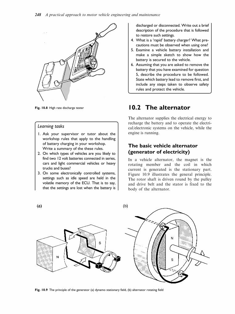
Learning tasks
1. Ask your supervisor or tutor about the
workshop rules that apply to the handling
of battery charging in your workshop.
Write a summary of the these rules.
2. On which types of vehicles are you likely to
find two 12 volt batteries connected in series,
cars and light commercial vehicles or heavy
trucks and buses?
3. On some electronically controlled systems,
settings such as idle speed are held in the
volatile memory of the ECU. That is to say,
that the settings are lost when the battery is
discharged or disconnected. Write out a brief
description of the procedure that is followed
to restore such settings.
4. What is a ‘rapid’ battery charger? What pre-
cautions must be observed when using one?
5. Examine a vehicle battery installation and
make a simple sketch to show how the
battery is secured to the vehicle.
6. Assuming that you are asked to remove the
battery that you have examined for question
5, describe the procedure to be followed.
State which battery lead to remove first, and
include any steps taken to observe safety
rules and protect the vehicle.
10.2 The alternator
The alternator supplies the electrical energy torecharge the battery and to operate the electri-cal/electronic systems on the vehicle, while theengine is running.
The basic vehicle alternator(generator of electricity)
In a vehicle alternator, the magnet is therotating member and the coil in whichcurrent is generated is the stationary part.Figure 10.9 illustrates the general principle.The rotor shaft is driven round by the pulleyand drive belt and the stator is fixed to thebody of the alternator.
Fig. 10.8 High rate discharge tester
Fig. 10.9 The principle of the generator (a) dynamo stationary field, (b) alternator rotating field
248 A practical approach to motor vehicle engineering and maintenance

Figure 10.10 shows how the electro motiveforce [e.m.f] (voltage) produced by this simplerotating magnet and stator coil varies duringone complete revolution (360) of the magneticrotor.
Alternating current (a.c.)
Alternating current, as produced by this sim-ple alternator, is not suitable for chargingbatteries. The alternating current must bechanged into direct current (d.c.). The devicethat changes a.c. to d.c. is the rectifier. Vehi-cle rectifiers make use of electronic devices,such as the p–n junction diode. The propertyof the diode that makes it suitable for usein a rectifier is that it will pass current inone direction but not the other. Figure 10.11demonstrates the principle of the semi-conductor diode.
Using a single diode as a simple halfwave rectifier
As a guide to the principle of operation of theactual rectifier as used in a vehicle alternator,we think that it is useful to briefly consider theoperation of the simple half-wave rectifiershown in Fig. 10.12.
In this simple rectifier the negative half of thewave is ‘blocked’ by the diode. The resultingoutput is a series of positive half waves sepa-rated by 190. In order to get a smooth d.c.supply it is necessary to use a circuit that con-tains several diodes. The bridge circuit rectifieris the basic approach that is used.
A full wave rectifier. The bridgecircuit
Figure 10.13(a) shows a full wave rectifier cir-cuit. There are 4 diodes, A, B, C and D whichare connected in bridge form. There is an a.c.input and a voltmeter is connected across theoutput resistor.
Reference to Fig. 10.13(b) shows how the cur-rent flows for one half of the a.c. cycle, and Fig.10.13(c) shows the current flow in the other halfof the a.c. cycle. In both cases, the current flowsthrough the load resistor R, in the same direction.Thus, the output is direct current and this isachieved by the ‘one way’ action of the diodes.
A typical vehicle alternator
The following description of the parts shown inFig. 10.14 should help to develop an under-standing that will aid the additional study and
Fig. 10.10 Diagram showing EMF produced in one complete
cycle relative to magnet position
Fig. 10.11 The principle of the diode (a) circuit for diode principle, (b) circuit symbol for a diode, (c) typical heavy duty diode
Electrical and electronic systems 249

training that will build the skills necessary forsuccessful work on electrical/electronic systems.
The ROTOR
This is where the magnetic field is generated by thecurrent that flows into the rotor windings throughthe slip rings and brushes. Figure 10.15 shows 3types of rotors that are used in Lucas alternators.
The rotor is made from an iron corearound which is wound a coil of wire. The
current in this coil of wire creates a magneticnorth pole at one end and a magnetic southpole at the other of the stator coil. The ironclaws of the rotor are placed on oppositeends of the rotor (field) winding. The ‘fin-gers’ of the claws are north or south mag-netic poles, according to the end of the fieldcoil that they are attached to. This makespairs of north and south poles around thecircumference of the rotor. The whole assem-bly is mounted on a shaft, which also has thedrive pulley fixed to it so that the rotor canbe driven by the engine.
The STATOR
These stators have a laminated iron core. Iron isused because it magnetises and de-magnetiseseasily, with a minimum of energy loss. Threeseparate coils are wound on to the stator core.A separate a.c. wave is generated in each wind-ing, as the rotor revolves inside the stator. Thestator windings are either star, or delta con-nected, according to alternator type.
The RECTIFIER
A 6 diode rectifier
A fairly commonly used bridge circuit of analternator rectifier uses 6 diodes, as shown inFig. 10.18. The stator windings are connected tothe diodes as shown in this figure.
In operation, a power loss occurs acrossthe diodes and in order to dissipate the heatgenerated the diodes are mounted on a heatsink which conducts the heat away into the
Fig. 10.12 The half-wave rectifier
Fig. 10.13 The full-wave rectifier (a) complete bridge circuit,
(b) current flow for one half of the voltage waveform,
(c) current flow for the other half of the voltage waveform
250 A practical approach to motor vehicle engineering and maintenance

atmosphere. Typical diode packs are shownin Fig. 10.19.
The voltage REGULATOR
The voltage regulator is an electronic circuit thatholds the alternator voltage to approximately14 volts on a 12 volt system, and approximately28 volts on a 24 volt system. It operates by sen-sing either the voltage at the alternator (machinesensing), or at the battery (battery sensing). The
regulator controls the amount of current that issupplied to the rotor field winding and this altersthe strength of the magnetic field and hence thealternator output voltage.
The BRUSHES and BRUSHBOX
The brushes carry the current to the sliprings, and from there to the rotor winding.Alternator brushes are normally made fromsoft carbon because it has good electrical
Fig. 10.14 The main component parts of an alternator
Fig. 10.15 Alternator rotors (electromagnets) Fig. 10.16 A selection of alternator stators
Electrical and electronic systems 251
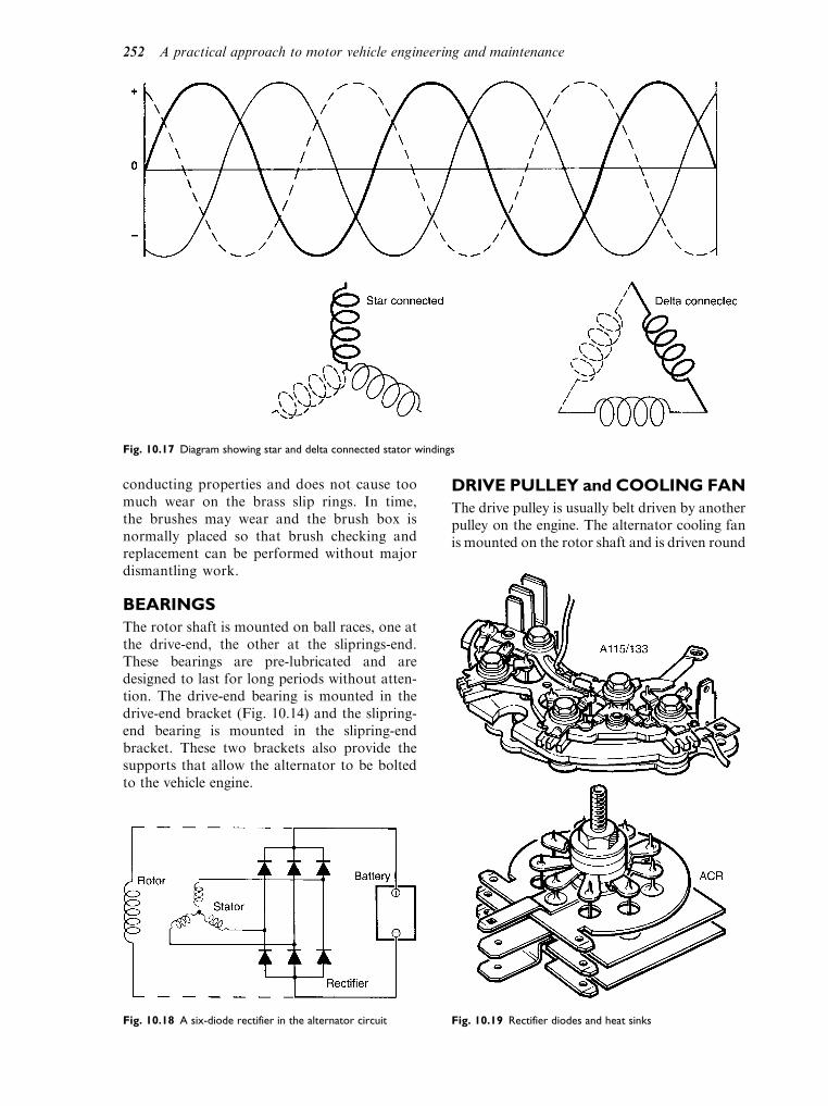
conducting properties and does not cause toomuch wear on the brass slip rings. In time,the brushes may wear and the brush box isnormally placed so that brush checking andreplacement can be performed without majordismantling work.
BEARINGS
The rotor shaft is mounted on ball races, one atthe drive-end, the other at the sliprings-end.These bearings are pre-lubricated and aredesigned to last for long periods without atten-tion. The drive-end bearing is mounted in thedrive-end bracket (Fig. 10.14) and the slipring-end bearing is mounted in the slipring-endbracket. These two brackets also provide thesupports that allow the alternator to be boltedto the vehicle engine.
DRIVE PULLEY and COOLING FAN
The drive pulley is usually belt driven by anotherpulley on the engine. The alternator cooling fanis mounted on the rotor shaft and is driven round
Fig. 10.17 Diagram showing star and delta connected stator windings
Fig. 10.18 A six-diode rectifier in the alternator circuit Fig. 10.19 Rectifier diodes and heat sinks
252 A practical approach to motor vehicle engineering and maintenance

with it. This fan passes air through the alternatorto prevent it from overheating.
Externally, alternators all look very muchalike, but they vary greatly in performanceand internal construction. The descriptiongiven here is intended to provide an introduc-tion to the topic. When working on a vehicle,it is essential to have access to the informa-tion relating to the actual machine beingworked on.
Alternator testing
Before starting on the alternator test procedure,there are a few general points about care ofalternators that need to be made:
. Do not run the engine with the alternator leadsdisconnected. (Note that in the tests that fol-low the engine is switched off and the ammeteris connected before re-starting the engine).
. Always disconnect the alternator and batterywhen using an electric welder on the vehicle.Failure to do this may cause stray currents toharm the alternator electronics.
. Do not disconnect the alternator when theengine is running.
. Take care not to reverse the battery connections.
With these points made we can turn ourattention to the alternator tests. As with anytest a thorough visual check should first bemade. In the case of the alternator this willinclude:
. Check the drive belt for tightness and condition;
. Check leads and connectors for tightness andcondition;
. Ensure that the battery is properly charged;
. Check any fuses in the circuit.
Alternator output tests
The question of whether to repair or replacean alternator is a subject of debate. However,one thing that is certain is the need to be ableto accurately determine whether or not thealternator is charging properly. The test proce-dure shown in Fig. 10.21 shows the procedurefor checking alternator current output underworking conditions.
The test link will be a cable with suitablecrocodile clips. This link must be securelyattached to ensure proper connections. Theammeter connections must also be secure,with the cables and the meter safely posi-tioned to ensure accurate readings and toavoid mishaps.
The drive belt tension must also be checked,as shown in Fig. 10.22.
The belt tension may also be checked by meansof a torque wrench, or a Burroughs type tensiongauge, as shown in Fig. 10.23. If the belt is tootight (excessive tension) alternator bearings maybe damaged; and if the tension is insufficientthe drive belt may slip. This will cause a loss of
Fig. 10.20 The alternator drive pulley and cooling fan
Fig. 10.21 Alternator output tests
Electrical and electronic systems 253

alternator power and, in time, can lead to wornpulleys, hence the reason for knowing what thetension should be and setting it accurately.
10.3 The starter motor
The starter motor shown in Fig. 10.24 is fairlytypical of starter motors in modern use.
Most modern starter motors are of the pre-engaged type. This means that the drive pinionon the starter motor is pushed into engagementwith the ring gear on the engine flywheel beforethe starter motor begins to rotate and start theengine.
The amount of torque (turning effect) that thestarter motor can generate is quite small and ithas to be multiplied to make it strong enough torotate the engine crankshaft at about 100 revo-lutions per minute (RPM). This multiplicationof torque is achieved by the ratio of the numberof teeth on the flywheel divided by the number ofteeth on the starter pinion. In the example shownin Fig. 10.25, the ratio is 10 to 1.
In the starter motor drive shown in Fig. 10.26,the pinion is moved into engagement by theaction of the solenoid on the operating lever.
The circuit in Fig. 10.27 shows that there aretwo solenoid coils that are energised when thestarter switch is closed. One coil is the holdingcoil and the other is the closing coil.
Fig. 10.22 Checking the drive belt tension
Fig. 10.23 Using the belt tension gauge
Fig. 10.24 A starter motor
Fig. 10.25 Gear ratio of a starter pinion and flywheel gear
Fig. 10.26 The operating lever
254 A practical approach to motor vehicle engineering and maintenance

The armature (plunger) of the solenoid isattached to the operating lever. When thepinion is properly engaged, the heavy currentcontacts of the solenoid will close and thestarter motor will rotate; this action by-passesthe closing coil and the holding coil remainsenergised until the starter switch is released.The plunger then returns to the normalposition, taking the starter pinion out ofengagement with the flywheel.
The starter motor pinion must be taken out ofengagement with the flywheel immediately theengine starts. An engine will normally start atapproximately 100 rpm. If the starter motorremains in engagement, the engine will drivethe starter motor at high speed (because ofthe gear ratio) and this will destroy thestarter motor. To guard against such damage,pre-engaged starter motors are equipped with afree wheeling device. A common example ofsuch an over-run protection device is the rollerclutch drive assembly shown in Fig. 10.28. Theinner member is fixed to the starter motor shaftand the outer member to the starter motorpinion.
This is a convenient point at which to have alook at some tests that can be used to tracefaults in starter motor circuits.
Testing starter motor circuits
As with all diagnostic work, it is advisable toadopt a strategy. One strategy that works well isthe six step approach. The six steps are:
1. collect evidence2. analyse evidence3. locate the fault4. find the cause of the fault and remedy it5. rectify the fault (if different from 4)6. test the system to verify that repair is correct.
In the case of a starter motor system andassuming that the starter motor does not oper-ate when the switch is on, step 1 of the six stepswill include a visual check to see whether allreadily visible parts such as cables, etc., are inplace and secure. The next step would be tocheck the battery. An indication of batterycondition can be obtained by switching on theheadlights. If the starter switch is operated withthe headlights on and the lights go dim, there isa case for a battery test, as described in thesection on batteries.
If the battery condition is correct, there aresome voltmeter tests that can be performed tocheck various parts of the starter motor circuit.For these tests, it is best to use an assistant tooperate the starter switch because it is unwise toattempt to make the meter connections andobserve the meter readings in the vicinity ofthe starter motor and attempt to operate thestarter switch simultaneously. The meter mustbe set to the correct d.c. range and clips shouldbe used so that secure connections can be madeto the various points indicated.
To avoid unwanted start up, the ignition sys-tem should be disabled. On a coil ignitionsystem, the low tension lead between the coiland distributor should be disconnected. On acompression ignition (diesel) engine, the fuelsupply should be cut off, probably by operatingthe stop control. The instructions that relate tothe vehicle being worked on must be referred to;this warning is particularly important whenworking on Engine Management Systems,because fault codes may be generated.
Figure 10.29 shows the test to check voltageat the battery terminals under load.
Here the battery voltage is being checkedwhile the starter switch is being operated. For
Fig. 10.27 The starter solenoid
Fig. 10.28 Starter pinion over-run protection
Electrical and electronic systems 255

a 12 volt system on a petrol engined vehicle, thevoltmeter should show a reading of approxi-mately 10 volts. On diesel engined vehicle, theload on the battery is higher and the voltagereading will be lower, approximately 9 voltsshould be obtained.
The starter terminal voltage
The purpose of the test shown in Fig. 10.30, isto check the heavy current circuit of the star-ter motor and the condition of the solenoidcontacts. When the starter motor switch is in
the start position, the voltage recordedbetween the input terminal and earth shouldbe within 0.5 volt of the battery voltage onload. If that voltage was 10.5 volts, thenthe voltage recorded here should be at least10 volts.
Checking the solenoid contacts
Should the starter motor voltage under loadbe low, it is possible that the heavy currentsolenoid contacts are defective. The testshown in Fig. 10.31 checks for voltage drop
0
5 10 15 20
Volts
Fig. 10.29 Checking battery voltage under load
0
5 10 15 20
Volts
Fig. 10.30 Starter motor voltage test (under load)
256 A practical approach to motor vehicle engineering and maintenance

across the solenoid contacts. Good contactswill produce little or no voltage drop. Thevoltmeter must be connected, as shown, tothe two heavy current terminals of the sole-noid. When the starter switch is in the offposition, the voltmeter should read batteryvoltage. When the starter switch is in thestart position, the voltmeter reading shouldbe zero.
Checking the earth circuit
Because vehicle electrical systems rely on a goodearthing circuit, such as metallic contactbetween the starter and the engine, and otherfactors such as earthing straps, this part of thecircuit needs to be maintained in good order.The test shown in Fig. 10.32 checks this part ofthe starter circuit. When the starter motorswitch is turned to the on position, the voltmetershould read zero. If the reading is 0.5 volt or
more, there is a defect in the earth circuit, agood visual examination should help to locatethe problem.
Note
These tests are based on Lucas recommenda-tions. Lucas sell a range of inexpensive,pocket-size test cards. These are recommendedfor use by those who are learning about vehi-cle maintenance. The one that relates to 12volt starting systems has the referenceXRB201. We believe that other equipmentmanufacturers produce similar aids to faultdiagnosis.
Learning tasks
Note
In most cases, these the procedure for
performing the practical tasks is detailed in
the text. However, you should always seek
the advice of your supervisor before you
start.
Working on vehicles can be dangerous so
you must not attempt work that you have not
been trained for. When you are in training you
must always seek the permission of your super-
visor before attempting any of the practical
work.
In the case of the first task you will need to
have been trained before you can read out the
fault codes.
Fig. 10.31 Checking the soleniod contacts
0
5 10 15 20
Volts
Fig. 10.32 Testing voltage drop on the earth circuit
Electrical and electronic systems 257

Part of the purpose of these practical tasks is
to assist you in building up a portfolio of evi-
dence for your NVQ. You should, therefore,
keep the notes and diagrams that you make
neatly in a folder.
1. With the aid of diagrams, where necessary,
describe the procedure for obtaining fault
codes from an ECU on a vehicle system that
you are familiar with.
2. Write down the procedure for removing a
battery from a vehicle. Make careful notes
of the safety precautions and specify which
battery terminal should be disconnected
first.
3. Describe the tools and procedures
for checking the state of charge of a battery.
4. Carry out a check of the charging rate of
an alternator. Make a list of the tools and
equipment used and give details of the way
in which you connected the test meter.
Make a note of the voltage values
recorded.
5. Make a sketch of the provision made for
tensioning the alternator drive belt on
any vehicle that you have worked on.
Explain why drive belt tension is important.
State the types of problems that may arise if
an alternator belt is not correctly adjusted.
6. With the aid of diagrams, explain how to
check for voltage at the starter motor
terminal when the engine is being cranked.
7. Examine the leads that are connected to the
headlights on a vehicle. Make a note of the
colours of the cable insulation. Obtain a
wiring diagram for the same vehicle and, by
reference to the wiring diagram, and the
colours that you have observed the cables
to be, locate the headlamp cables on the
wiring diagram.
8. Make a note of the headlamp alignment
equipment that is used in your workshop.
Describe the procedure for carrying out
a headlamp alignment check. Make a sketch
of the method used to adjust headlamp
alignment on any vehicle that you have
worked on.
9. Give details of the fuseboxes on any vehi-
cle that you are familiar with. State the
type and current rating of the side and tail
lamp fuse.
10. Write down the precautions that should
be taken to protect vehicle electrical
equipment before attempting any electric
arc welding on the vehicle.
Self assessment questions
1. The function of the heat sink part of the recti-
fier diode pack in an alternator is to:
(a) conduct heat away from the diodes in order
to protect them
(b) provide a solid base for the transistors
(c) act as a voltage regulator
(d) prevent the stator from overheating
2. Machine sensing, where the alternator output
voltage is used to vary the current in the rotor
windings, is a method of controlling:
(a) the phase angle of the a.c. output
(b) the voltage output of the alternator
(c) the self exciting voltage of the alternator
(d) the brush pressure on the slip rings
3. A slack alternator drive belt may cause the:
(a) engine to overheat
(b) engine to lose speed
(c) battery to become discharged
(d) charging rate to be too high
4. Alternator generate a.c. is converted to d.c. by:
(a) Zener diode
(b) the regulator
(c) the battery
(d) the slip rings
5. The regulated voltage output of the alternator
on a 12 volt system should be:
(a) exactly 12 volts
(b) 10.9 volts
(c) approximately 13 to 15 volts
(d) 18 volts
6. The maximum permissible voltage drop on a
12 volt starter motor system as measured
across the battery terminals when the starter
motor is operating is:
(a) 0.2 volts
(b) 2 volts
(c) 5 volts
(d) 0.5 volts
7. If the gear ratio between a starter motor and
the flywheel ring gear is 10:1, and the starter
motor generates a torque of 5 Nm, the tor-
que at the flywheel will be:
(a) 50 Nm
(b) 105 Nm
(c) 0.5 Nm
(d) 50 amperes
8. On a pre-engaged type of starter motor, over-
speeding of the armature is prevented by:
(a) the back e.m.f. in the windings
(b) Fleming’s right-hand rule
(c) a free-wheeling clutch
(d) manual withdrawal of the pinion
258 A practical approach to motor vehicle engineering and maintenance

9. At normal room temperature, the relative
density of the electrolyte in a lead acid battery
should be:
(a) 13.6
(b) 12.6
(c) 1.28
(d) 0.128
10. A high rate discharge tester:
(a) should always be used to test a flat battery
(b) should only be used if the battery is at
least 70% charged
(c) can only be used on nickel alkaline cells
(d) determines the Watt-hour capacity of the
battery
Electrical and electronic systems 259

11Ignition systems
Topics covered in thischapter
Ignition systems – coil, capacitor (condenser)
Electronic ignition systems,
non-electronic ignition systems
Fault tracing and service and maintenance
procedures
Sensors and pulse generators
Ignition timing
Diagnostic trouble codes
The purpose of the ignition system is to provide aspark to ignite the compressed air–fuel mixturein the combustion chamber. The spark must beof sufficient strength to cause ignition and itmust occur at the correct time in the cycle ofoperations. The ignition system is the means bywhich the 12 volt supply from the vehicle batteryis converted into many thousands of volts thatare required to produce the spark at the sparkingplug, as illustrated by Figs 11.1 and 11.2.
11.1 Producing the highvoltage required to causeignition
Electromagnetism was discussed in the electricalprinciples section. It is these electro-magneticprinciples that are employed in the inductioncoil type of ignition system.
In this coil there are two windings, a primarywinding and a secondary winding. The primarywinding consists of a few hundred turns of lac-quered copper wire. The secondary windingconsists of several thousand turns of thin, lac-quered copper wire. The primary winding iswound around the outside of the secondary
winding because the heavier current that it car-ries generates heat which needs to be dissipated.The layers of windings are normally electricallyinsulated from each other by a layer of insulat-ing material.
In the centre of the secondary winding there is alaminated soft iron core. The purpose of this
Fig. 11.1 Position of the spark in a reciprocating (piston)
Fig. 11.2 Position of the spark in a rotary engine

laminated core is to concentrate the magnetic fieldthat is produced by the current in the coil wind-ings. The laminations between the coil’s outercasing and the windings serves a similar purpose.
The interior parts of the coil are supported ona porcelain base. In some cases the coil may befilled with a transformer oil to improve electri-cal insulation and to aid heat dissipation.
Principle of operation
The actual size of the secondary voltage (hightension (HT) voltage) is related to the turnsratio of the coil, for example several thousandturns in the secondary winding and a few hun-dred turns in the primary winding.
In order for the ignition system to operate,the primary winding current must be switchedon and off, either by electronic means, or in thecase of older systems the contact breaker.
Figure 11.4 shows a simple ignition coilprimary circuit. Current from the vehicle bat-tery flows through the primary winding viathe ignition switch and the closed contactbreaker points, to earth. The current of about3 amperes in the primary winding causes astrong magnetic field, which is concentrated
by the soft iron laminations at the coil centreand the outer sheath of iron. It should beremembered that the secondary winding isinside the primary winding, so the magneticfield from the primary winding also affectsthe secondary winding. A primary purposeof the primary winding is to create the strongmagnetic field that will induce the high volt-age in the secondary circuit.
Methods of inducing the high tension(HT) secondary voltage
Switching off the primary current by openingthe contact breaker points has two major effectswhich are caused by the collapsing inwards ofthe magnetic field. These two effects are:
1. Self induction – a voltage of approximately250 volts is generated across the ends ofthe primary winding. The direction of thisinduced voltage in the primary winding issuch that it opposes the change which pro-duced it, that is to say that it attempts tomaintain the same direction of currentflow.
2. Induction – a high voltage (several thousandvolts kV) is generated across the ends of thesecondary winding.
Secondary circuit
Figure 11.5 shows the secondary circuit as wellas the primary circuit of the simplified system.One end of the secondary winding (thousandsof turns of fine copper wire) is connected tothe HT terminal in the coil tower, the otherconnected to the primary winding at one ofthe low tension (LT) connections. When theprimary winding is connected to the secondary
Fig. 11.3 The type of ignition coil that has been commonly
used on vehicles
Fig. 11.4 A basic primary circuit of an ignition coil with contacts
closed
Ignition systems 261

winding it is known as ‘auto transformer’. Theinduced primary voltage is added to the sec-ondary voltage.
The capacitor (condenser)
The simplified ignition system described abovewould not work well because the induced volt-age in the primary winding would be strongenough to bridge the contact breaker gap andcarry current to earth. This would reduce thesecondary voltage and also lead to excessivesparking at the contact breaker points. Thepoints would ‘burn’ and the efficiency of thesystem would be seriously impaired. This prob-lem is overcome by fitting a suitable capacitor(approximately 0.2 uF) across (in parallel with)the points.
Figure 11.6 shows the capacitor in circuit.One terminal of the capacitor is connected tothe low tension connection on the distributorand the other terminal is earthed.
Capacitors store electricity so that when, inthe case of the coil ignition system, the con-tact points begin to open, the self-inducedcurrent from the primary winding will flowinto the capacitor instead of ‘jumping’ acrossthe points gap. This flow of current will con-tinue until the capacitor is fully charged.When the capacitor is fully charged, it willautomatically discharge itself back into theprimary winding. This capacitor dischargecurrent is in the opposite direction to theoriginal flow and it helps to cause a rapidcollapse of the magnetic field. This, in turn,leads to a much higher HT voltage from thesecondary winding.
Coil polarity
Electrons flow from negative to positive andthermal activity (heat) also aids electron gener-ation. For this reason, the insulated (central)hotter electrode of the spark plug is made nega-tive in relation to the HT winding.
The result of this polarity direction is that alower voltage is required to generate a sparkacross the plug gap. To ensure that the correctcoil polarity is maintained the L.T. connec-tions on the coil are normally marked as þand .
The coil polarity is readily checked bymeans of the normal garage type oscilloscope.Figure 11.8 shows the inverted waveform thatresults from incorrect connection of the coil,or the fitting of the wrong type of coil for thevehicle under test.
Fig. 11.5 Typical primary and secondary circuits of a coil
Fig. 11.6 The ignition circuit with the capacitor in place
Fig. 11.7 Polarity of spark plug electrodes
262 A practical approach to motor vehicle engineering and maintenance
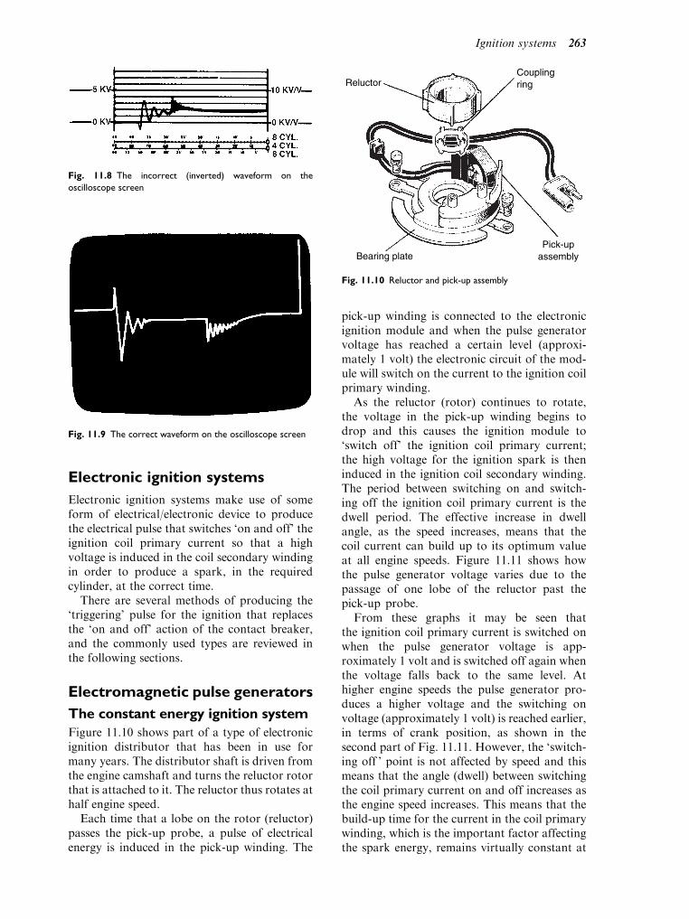
Electronic ignition systems
Electronic ignition systems make use of someform of electrical/electronic device to producethe electrical pulse that switches ‘on and off’ theignition coil primary current so that a highvoltage is induced in the coil secondary windingin order to produce a spark, in the requiredcylinder, at the correct time.
There are several methods of producing the‘triggering’ pulse for the ignition that replacesthe ‘on and off’ action of the contact breaker,and the commonly used types are reviewed inthe following sections.
Electromagnetic pulse generators
The constant energy ignition system
Figure 11.10 shows part of a type of electronicignition distributor that has been in use formany years. The distributor shaft is driven fromthe engine camshaft and turns the reluctor rotorthat is attached to it. The reluctor thus rotates athalf engine speed.
Each time that a lobe on the rotor (reluctor)passes the pick-up probe, a pulse of electricalenergy is induced in the pick-up winding. The
pick-up winding is connected to the electronicignition module and when the pulse generatorvoltage has reached a certain level (approxi-mately 1 volt) the electronic circuit of the mod-ule will switch on the current to the ignition coilprimary winding.
As the reluctor (rotor) continues to rotate,the voltage in the pick-up winding begins todrop and this causes the ignition module to‘switch off’ the ignition coil primary current;the high voltage for the ignition spark is theninduced in the ignition coil secondary winding.The period between switching on and switch-ing off the ignition coil primary current is thedwell period. The effective increase in dwellangle, as the speed increases, means that thecoil current can build up to its optimum valueat all engine speeds. Figure 11.11 shows howthe pulse generator voltage varies due to thepassage of one lobe of the reluctor past thepick-up probe.
From these graphs it may be seen thatthe ignition coil primary current is switched onwhen the pulse generator voltage is app-roximately 1 volt and is switched off again whenthe voltage falls back to the same level. Athigher engine speeds the pulse generator pro-duces a higher voltage and the switching onvoltage (approximately 1 volt) is reached earlier,in terms of crank position, as shown in thesecond part of Fig. 11.11. However, the ‘switch-ing off ’ point is not affected by speed and thismeans that the angle (dwell) between switchingthe coil primary current on and off increases asthe engine speed increases. This means that thebuild-up time for the current in the coil primarywinding, which is the important factor affectingthe spark energy, remains virtually constant at
Fig. 11.8 The incorrect (inverted) waveform on the
oscilloscope screen
Fig. 11.9 The correct waveform on the oscilloscope screen
Bearing platePick-up
assembly
ReluctorCouplingring
Fig. 11.10 Reluctor and pick-up assembly
Ignition systems 263

all speeds. It is for this reason that ignitionsystems of this type are known as ‘constantenergy systems’. It should be noted that this‘early’ type of electronic ignition still incorpo-rates the centrifugal and vacuum devices forautomatic variation of the ignition timing.
Digital (programmed) ignitionsystem – Hall effect sensor
Programmed ignition makes use of computertechnology and it permits the mechanical,pneumatic and other elements of the con-ventional distributor to be dispensed with.Figure 11.12 shows an early form of digitalignition system.
The control unit (ECU or ECM) is a smalldedicated computer which has the ability toread input signals from the engine, such asspeed, crank position and load. These readingsare compared with data stored in the computermemory and the computer then sends outputsto the ignition system. It is traditional to repre-sent the data, which is obtained from enginetests, in the form of a 3-dimensional map, asshown in Fig. 11.13.
Any point on this map may be represented bya number reference. For example, engine speed1 000 rpm, manifold pressure (engine load) 0.5bar, ignition advance angle 5 degrees. Thesenumbers can be converted into computer (bin-ary) codewords, made up of 0s and 1s (this iswhy it is known as digital ignition). The map isthen stored in computer memory, where theprocessor of the control unit can use it to pro-vide the correct ignition setting for all engineoperating conditions.
In this early type of digital electronic igni-tion system, the ‘triggering’ signal is producedby a Hall effect sensor of the type shown inFig. 11.14.
High speed input /output waveforms
Preset voltage
Preset voltage
Enginerotation
Enginerotation
Enginerotation
Enginerotation
Currentlimit
Currentlimit
Dwell
Dwell
Low speed input /output waveforms
Coilcurrent
Coilcurrent
Pick-upoutputvoltage 0
0
Pick-upoutputvoltage
Fig. 11.11 Pick-up output voltage at low and high speeds
Distributorcover
Rotor armVaneswitch
Controlunit Vacuum pipe
to engine
Sparkplug
Ignition coil
Ignitionswitch
Battery
ECU socket
PIN 5PIN 2
PIN 9 9 8 7 6
12345PIN 8
PIN 4PIN 3
Triggervane
Distributor
Fig. 11.12 A digital ignition system
264 A practical approach to motor vehicle engineering and maintenance

When the metal part of the rotating vane isbetween the magnet and the Hall element thesensor output is zero and when the gaps inthe vane expose the Hall element to the mag-netic field, a voltage pulse is produced. In thisway, a voltage pulse is produced by the Hallsensor each time that a spark is required.Whilst the adapted form of the older typeignition distributor is widely used for electro-nic ignition systems, it is probable that thetrigger pulse generator driven by the crank-shaft and flywheel is more commonly used onmodern systems.
Opto-electronic sensing for theignition system
Figure 11.15 shows the electronic ignition photo-electronic distributor sensor used on a Kia.There are two electronic devices involved in theoperation of the basic device. One is a light
Advancein degrees
5001500
25003500
45005500
6500
Speedin RPM
Pressure(m bar)
90
70
50
30
10
Fig. 11.13 An ignition map that is stored in the ROM of the ECM
Trigger vane
Distributorshaft
Baseplate
Vaneswitch
Fig. 11.14 A Hall type sensor
Sensor
Disc
Led
Photodiode
DiscSlot(for Ne-signal)
Fig. 11.15 An opto-electronic sensor
Ignition systems 265

emitting diode (it converts electricity into light),the other is a photo diode that can be ‘switchedon’ when the light from the LED falls on it.
Another version of this type of sensor isshown in Fig. 11.16. Here the rotor plate has360 slits placed at 1 degree intervals for enginespeed sensing, and a series of larger holes forTDC indication that are placed nearer the cen-tre of the rotor plate. One of these larger slits iswider than the others and is used to indicateTDC for number 1 cylinder.
Distributorless ignition system
Figure 11.17 shows an ignition system for a4-cylinder engine. There are two ignition coils,one for cylinders 1 and 4, and another for cylin-ders 2 and 3. A spark is produced each time a pairof cylinders reaches the firing point, near topdead centre. This means that a spark occurs onthe exhaust stroke as well as on the power stroke.
For this reason, this type of ignition system issometimes known as the ‘lost spark’ system.
Figure 11.17 shows that there are two sensorsat the flywheel; one of these sensors registersengine speed and the other is the trigger for theignition. They are shown in greater detail inFigs 11.18 and 11.19 and they both rely on thevariable reluctance principle for their operation.
An alternative method of indicating the TDCposition is to use a toothed ring attached to theflywheel, which has a tooth missing at the TDCpositions, as shown in Fig. 11.19.
With this type of sensor, the TDC position ismarked by the absence of an electrical pulse,known as also a variable reluctance sensor.The other teeth on the reluctor ring, which areoften spaced at 10 degree intervals, are used toprovide pulses for engine speed sensing.
Direct ignition systems
Direct ignition systems are those where eachcylinder has a separate ignition coil which isplaced directly on the sparking plug, as shownin Fig. 11.20.
The trigger unit is incorporated in the coilhousing in order to protect the ECM againsthigh current and temperature.
Ignition system refinements
As the processing power of microprocessors hasincreased it is natural to expect that systemdesigners will use the increased power to pro-vide further features, such as combustion knocksensing and adaptive ignition control.
Optical pick-up
Rotor plate
TDCNo. 1
cylinder
Fig. 11.16 An alternative form of opto-electronic sensor
Engine load(vacuum)
ECU
Enginespeedsensor
+
−
Enginepositionsensor
Engineflywheel
Ringgearteeth
Twin doubleended coils
Pluggaps
Pluggaps
Fig. 11.17 A distributorless ignition system
266 A practical approach to motor vehicle engineering and maintenance

Knock sensing
Combustion knock is a problem that is associatedwith engine operation. Early motor vehicles wereequipped with a hand control that enabled thedriver to retard the ignition when the character-istic ‘pinking’ sound was heard. After the pinkinghad ceased the driver could move the controllever back to the advanced position. Electroniccontrols permit this process to be done automat-ically and a knock sensor is often included in themake up of an electronic ignition system.
Combustion knock sensors
A knock sensor that is commonly used in enginecontrol systems utilises the piezo-electric gener-ator effect. That is to say that the sensing ele-ment produces a small electric charge when it iscompressed and then relaxed. Materials such asquartz and some ceramics like PZT (a mixtureof platinum, zirconium and titanium) are effectivein piezo-electric applications. In the applicationshown, the knock sensor is located on the engineblock adjacent to cylinder number 3. In this posi-tion it is best able to detect vibrations arising fromcombustion knock in any of the 4 cylinders.
Because combustion knock is most likely tooccur close to top dead centre, in any cylinder,the control program held in the ECM memoryenables the processor to use any knock signalgenerated to alter the ignition timing by anamount that is sufficient to eliminate the knock.When knock has ceased, the ECM will advancethe ignition in steps, back to its normal setting.The mechanism by which vibrations arisingfrom knock are converted to electricity is illus-trated in Fig. 11.22.
The sensor is accurately designed and thecentre bolt that pre-tensions the piezo crystal isaccurately torqued so as to provide the correctsetting. The steel washer that makes up theseismic mass has very precise dimensions.When combustion knock occurs, the resultingmechanical vibrations are transmitted by theseismic mass to the piezoelectric crystal. The‘squeezing up’ and relaxing of the crystal inresponse to this action produces a small elec-trical signal that oscillates at the same frequencyas the knock sensor element. The electrical sig-nal is conducted away from the crystal by wiresthat are secured to suitable points on the crystal.
The tuning of the sensor is critical because itmust be able to distinguish between knock fromcombustion and other knocks that may arise
TDC peg
TDC sensor
Flywheel ring gear
Soft iron core
Winding
Engine speedsensorPermanent
magnet
Fig. 11.18 Details of engine speed and crank position sensor
Toothed wheel
Missingteeth
Crankshaftsensor
Fig. 11.19 Engine speed and position sensor that uses a
detachable reluctor ring
156EG16
Igniter
Secondarycoil
Primary coil
Plug cap
Iron core
Fig. 11.20 Direct ignition coil cross-section
Ignition systems 267
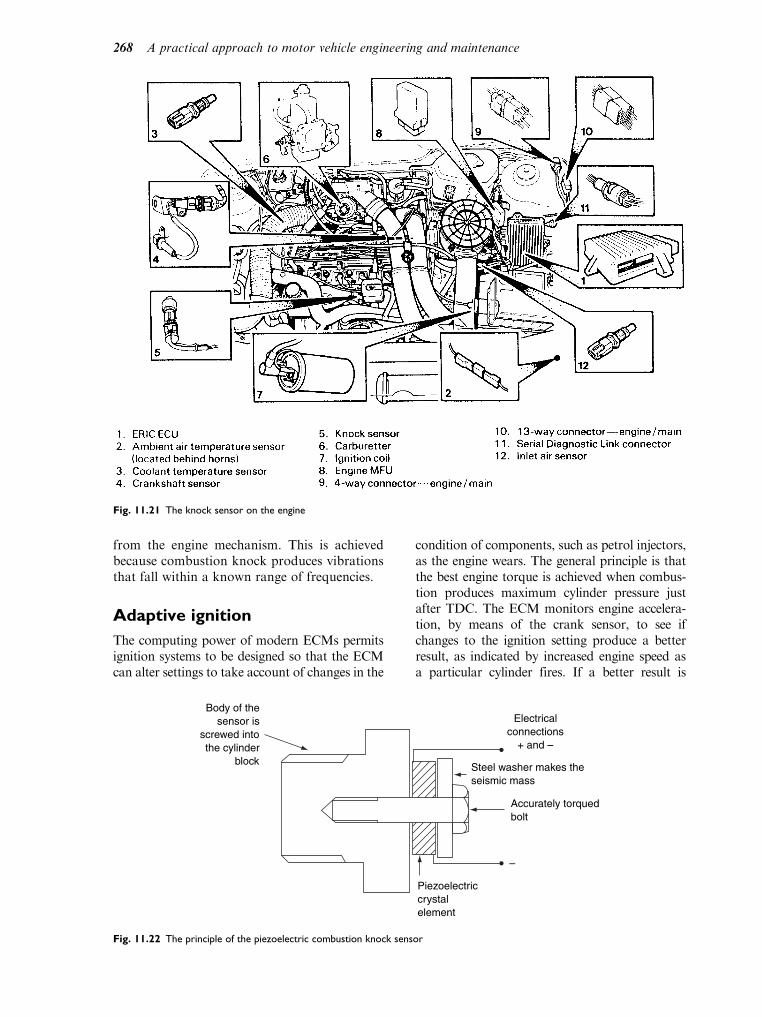
from the engine mechanism. This is achievedbecause combustion knock produces vibrationsthat fall within a known range of frequencies.
Adaptive ignition
The computing power of modern ECMs permitsignition systems to be designed so that the ECMcan alter settings to take account of changes in the
condition of components, such as petrol injectors,as the engine wears. The general principle is thatthe best engine torque is achieved when combus-tion produces maximum cylinder pressure justafter TDC. The ECM monitors engine accelera-tion, by means of the crank sensor, to see ifchanges to the ignition setting produce a betterresult, as indicated by increased engine speed asa particular cylinder fires. If a better result is
Fig. 11.21 The knock sensor on the engine
Body of thesensor is
screwed intothe cylinder
block
Electricalconnections
+ and –
–
Steel washer makes theseismic mass
Accurately torquedbolt
Piezoelectriccrystalelement
Fig. 11.22 The principle of the piezoelectric combustion knock sensor
268 A practical approach to motor vehicle engineering and maintenance

achieved, then the ignition memory map can bereset so that the revised setting becomes the onethat the ECM uses. This ‘adaptive learning strat-egy’ is now used quite extensively on computercontrolled systems and it requires technicians torun vehicles under normal driving conditions forseveral minutes after replacement parts andadjustments have been made to a vehicle.
11.2 Fault tracing,maintenance and repairof ignition systems
The majority of the following descriptions arebased on the use of a portable oscilloscope.However, for tests on the primary circuit of anignition system, a good-quality digital multi-meter will also serve most purposes.
Performance checks on pulsegenerators
If preliminary tests on the ignition circuit indi-cate that the pulse generator may be defective,checks of the following type can provide usefulinformation.
Magnetic (inductive) type ignitionpulse generator
The voltage output of a typical ignition pulsegenerator of this type varies with engine speedand the actual voltage varies considerablyaccording to manufacturer. However, the vol-tage waveform is of similar form for most makesand useful test information can be gained froma voltage test. There are two possible states for avoltage test: one is with the pulse generatordisconnected from the electronic module whena waveform of the type shown in Fig. 11.23Bosch should be produced and the other iswhen the pulse generator is connected to theelectronic module when the waveform shownin Fig. 11.24 should be produced. The differenceis accounted for by the fact that lower part ofthe pattern is affected by the loading from theelectronic module.
A digital voltmeter set to an appropriate a.c.range may also be used to check the output ofthis type of pulse generator. The voltages foreach pulse should be identical and the maximumvalue should be at the level given in the vehiclerepair data.
Other checks that can beperformed on the inductivetype pulse generator
Resistance check
If the sensor voltage is not correct it is possibleto conduct a resistance test that gives an indica-tion of the condition of the winding part of thesensor. Figure 11.25 gives an indication of theconnections used for this process.
Hall type sensor tests
A Hall type sensor is known as a passive devicebecause it operates by processing electricitythat is supplied to it and it can be expected tohave at least three cables at its connection.Figure 11.26 shows the approximate positionof the oscilloscope test probes on a Hall typeignition distributor.
If the test is being performed because theengine will not start, the purpose of the test willbe to check that there is a signal from the ignitiontrigger sensor. The oscilloscope, or meter, wouldbe connected as shown and the engine crankedover. The voltage pattern would be observed and,
Spez
20 V
412191
tz
Fig. 11.23 Waveform, pulse generator - unloaded
Spez
20 V
412192
tz
Fig. 11.24 Waveform, pulse generator - electronic module
connected
Ignition systems 269
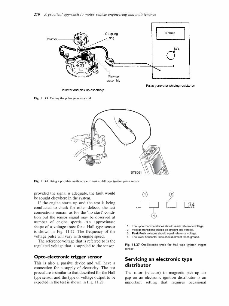
provided the signal is adequate, the fault wouldbe sought elsewhere in the system.
If the engine starts up and the test is beingconducted to check for other defects, the testconnections remain as for the ‘no start’ condi-tion but the sensor signal may be observed atnumber of engine speeds. An approximateshape of a voltage trace for a Hall type sensoris shown in Fig. 11.27. The frequency of thevoltage pulse will vary with engine speed.
The reference voltage that is referred to is theregulated voltage that is supplied to the sensor.
Opto-electronic trigger sensor
This is also a passive device and will have aconnection for a supply of electricity. The testprocedure is similar to that described for the Halltype sensor and the type of voltage output to beexpected in the test is shown in Fig. 11.28.
Servicing an electronic typedistributor
The rotor (reluctor) to magnetic pick-up airgap on an electronic ignition distributor is animportant setting that requires occasional
Fig. 11.25 Testing the pulse generator coil
ST8061
Fig. 11.26 Using a portable oscilloscope to test a Hall type ignition pulse sensor
1. The upper horizontal lines should reach reference voltage.2. Voltage transitions should be straight and vertical.3. Peak-Peak voltages should equal reference voltage.4. The lower horizontal lines should almost reach ground.
1 2
3
4
Fig. 11.27 Oscilloscope trace for Hall type ignition trigger
sensor
270 A practical approach to motor vehicle engineering and maintenance

checking. Figure 11.29(a) shows the rotorand magnetic pick up and Fig. 11.29(b) showsnon-magnetic, i.e. brass or plastic feeler gauges,being used to check the gap. The use of non-magnetic feeler gauges is important because,if steel is placed in this air gap, the electriccharge generated may damage to electroniccircuit.
Setting the static timing of anelectronic type distributor
The procedures described here applies to twotypes of distributors. One is the variablereluctance pulse generator type and the otheris a Hall effect pulse generator. It should benoted that the procedure will vary accordingto engine type and also to the type and makeof distributor. It is essential to have access tothe details relating to a specific application.Of course, if you are familiar with a particu-lar make of vehicle it is quite possible thatyou will be able to memorise the procedures.
Static timing – variable reluctancepulse generator
The cylinder to which the distributor is beingtimed must be on the firing stroke and the tim-ing marks, on the engine, must be accuratelyaligned. The distributor rotor must be pointingtowards the correct electrode in the distributorcap and the corresponding lobe of the reluctorrotor must be aligned with the pick up, as in thecase shown in Fig. 11.29. When the distributoris securely placed and the electrical connectionsmade, the final setting of the timing is achievedby checking the timing with the strobe light.Final adjustment can then be made by rotatingthe distributor body, in the required direction,prior to final tightening of the clamp.
Static timing Hall effect pulsegenerator
Figure 11.30 shows a Hall effect distributor, fordigital electronic ignition, where the distributoritself is provided with timing marks. With theengine timing marks correctly set, the cut-out inthe trigger vane must be aligned with the vaneswitch, as shown.
Should the setting require adjustment, thedistributor clamp is slackened, just sufficient to
1 2
4
3
5
1. The upper horizontal lines should reach reference voltage.2. Voltage transitions should be straight and vertical.3. Peak-Peak voltage should equal reference voltage.4. The lower horizontal lines should almost reach ground.5. Signal pulse width may vary due to size variations in the trigger wheel window.
Specifications may vary. Consult manufacturer’s specifications.
• Primary distributor triggering (optical)
Fig. 11.28 Oscilloscope voltage trace for opto-electronic type
ignition trigger sensor
Fig. 11.29 Checking the air gap between pick up and rotor Fig. 11.30 Static timing Hall effect pulse generator
Ignition systems 271

permit rotation of the distributor body. The dis-tributor is then rotated until the marks are aligned.After tightening the clamp and replacing all leads,etc., the engine may be started and the timingchecked be means of the stroboscopic light.
Diagnosis – secondary (highvoltage) side of ignition system
Firstly, it is important to Work in a Safe
Manner. Electric shock from ignition systemsmust be avoided; not only is the shock danger-ous in itself but it can also cause involuntarymuscular actions which can cause limbs to bethrown into contact with moving or hot parts.
Tests on distributor type ignitionsystems
The king lead and the HT lead to number 1 cylin-der are normally connected to the oscilloscope, asshown in Fig. 11.31.
A typical oscilloscope display for a distribu-tor type ignition is shown in Fig. 11.32.
These displays show the firing voltage for num-ber 1 cylinder. The parade pattern shows the volt-
age of the remaining cylinders as displayed acrossthe screen, in the firing order, from left to right.
Tests on distributorless ignitionsystems
In this case there is no king lead so the inductivepick up is clamped to the HT leads individually,as close as possible to the spark plug, as shownin Fig. 11.33.
The screen display obtained from such a testshows data about engine speed and burn timeand voltage. These and other details may moreeasily be seen by taking an enlargement of thetrace for a single cylinder as shown in Fig. 11.34.
The details are:
1. Firing line – this represents the high voltageneeded to cause the spark tobridge theplug gap;
2. The spark line;3. Spark ceases;4. Coil oscillations;5. Intermediate section (any remaining energy
is dissipated prior to the next spark);
STAO10BO
Fig. 11.31 Oscilloscope connections for obtaining ignition trace
Fig. 11.32 Oscilloscope displays of secondary ignition
voltage – single pattern and parade
Fig. 11.33 The oscilloscope set-up for obtaining a secondary
voltage trace from a DIS
Fig. 11.34 Details of the HT voltage trace for a single cylinder
272 A practical approach to motor vehicle engineering and maintenance

6. Firing section (represents burn time);7. Dwell section;8. Primary winding current is interrupted by
transistor controlled by the ECM;9. Primary winding current is switched on to
energise the primary. The dwell period isimportant because of the time required forthe current to reach its maximum value.
A comparison of the secondary voltage tracesfor each of the cylinders should show them to bebroadly similar. If there are major differencesbetween the patterns, then it is an indication of adefect.
For example, a low firing voltage (1) indicateslow resistance in the HT cable or at the sparkplug. The low resistance could be attributed toseveral factors including oil or carbon fouledspark plug, incorrect plug gap, low cylinderpressure or defective HT cable. A high voltageat (1) indicates high resistance in the HT cableor at the spark plug. Factors to consider hereinclude a loose HT lead, wide plug gap or anexcessive amount of resistance has developed inthe HT cable. Table 11.1 below summarises themajor points:
Sparking plugs can be removed and exam-ined; HT leads can also be examined for tight-ness in their fittings and their resistance can bechecked with an ohmmeter. Resistive HT leadsare used for electrical interference purposes andthey should have a resistance of approximately15 000 to 25 000 ohms per metre length.
As in all cases, it is important to have to handthe information and data that relates to thesystem being worked on.
Direct on sparking plug systems
Direct ignition systems of the type shownin Fig. 11.19, are normally controlled by theengine management computer (ECM) whichincorporates self diagnostics that give detailedinformation about ignition faults. Should amisfire be attributed to one of the ignition coils,the condition of the coil may be checked byconducting a resistance test on the primaryand secondary windings. The primary windingof the coil will have a resistance of approxi-mately 1 ohm, whilst the secondary windingresistance is normally 5 000 ohms to 10 000 ohms.
Diagnostic trouble codes (DTCs)
Modern engine management use European orUS on-board diagnostic standards. Europeanon-board diagnostic systems (EOBD) requirethat emissions related trouble codes (DTCs)are available through a standard connectionthat permits an approved repairer to gain accessto the DTCs by means of an appropriate scantool. The form of the EOBD diagnostic plugand the recommended position of it on thevehicle is shown in Fig. 11.35.
Table 11.1 Factors affecting firing voltage
Factor High firing
voltage
Low firing
voltage
Spark plug gap Wide Small
Compression pressure Good Low
Air–fuel ratio Weak Correct
Ignition point Late Early
BO
SC
H
12
3
45
6 98
7
1 684 452 346
1011
12 1514 16
13
CARBANBCHL
Fig. 11.35 The leads for the Bosch KTS 300 pocket system tester
Ignition systems 273

Because the vehicle emissions are affected bya number of vehicle systems, such as fuellingand ignition, the ECM is programmed to recordand report on a range of faults in these systemsthat may contribute to a vehicle’s failure to meetemissions regulation limits.
An example of a DTC is:
DTC Function
PO300 Random/multiple cylinder misfire
detected
Analysis of this diagnostic trouble code
This DTC tells us that there is a misfire. Todetermine the cause will require further testingof the ignition related systems in order to tracethe cause and effect a repair. Some on-boarddiagnostics may go deeper into the causes ofthe misfire, in which case the task of fault tra-cing should be made simpler.
11.3 Contact breaker typeignition systems
Each time a spark is required the contactbreaker points must open and close. For afour stroke engine this means that a spark isrequired once for each two revolutions of theengine crank. To achieve this the cam thatoperates the contact breaker is normallydriven from the engine camshaft. For multi-cylinder engines the cam normally has thesame number of lobes as there are cylinders.A typical example of a cam and contactbreaker mechanism for a four cylinder engineis shown in Fig. 11.36.
In order to get an idea of the speed of oper-ation of the contact breaker points, considerwhat happens at an engine crank speed of 3 600revolutions per second (rpm). The cam of the
distributor is rotating at half this speed, i.e.1 800 rpm. That is equivalent to 30 rpm. In our 4cylinder engine the contact points will open andclose 4 times for each revolution of the cam andthis means that they will open and close30 4¼ 120 times a second. This speed obviouslyvaries with engine speed but it is evident that thecontact breaker and its operating mechanism issubject to a lot of hard work. To give reliabilityand durability the cam is made from high-qualitysteel with a hard wearing surface. The movingcontact is operated by a ‘heel’ made from hardwearing, electrically insulating material, usuallyhigh-quality plastic. The contact points are madefrom a steel alloy containing tungsten, enablingthe points to cope with the burning action thatarises from electrical action as the points open.This electrical action at the points will, over time,lead to pitting of one contact and the building upof a corresponding ‘pip’ on the other point; thisis known as ‘pitting and piling’. The electricalaction that leads to this effect also causes a darklayer of oxide to form on the contact point faces.These factors lead to a deterioration of ignitionsystem performance and requires the ‘points’ tobe checked and, if they are pitted and blackened,the usual procedure is to replace them.
Sliding contact (self cleaning)type of contact breaker
Amethod that is used to overcome the problemof pitting is to use sliding contacts. In slidingcontacts, the fixed contact has a larger facearea than the moving one. In addition to thenormal opening and closing action, the movingcontact is made to slide across the face of thefixed contact.
Figure 11.37, shows a sliding contactassembly. The contact breaker heel has two
Fig. 11.36 The distributor cam and contact breaker Fig. 11.37 A sliding contact assembly
274 A practical approach to motor vehicle engineering and maintenance

ribs at its base and these ribs rest in rampsformed in the forked heel actuator. Thisforked heel actuator pivots on the contactbreaker pivot post. The fork in the heelactuator engages with a pin which is fixed tothe distributor base plate. When the vacuumadvance and retard mechanism rotates thebearing plate, the heel ribs ride up the rampsin the actuator plate and cause the movingcontact to slide across the fixed contact, asshown in Fig. 11.38. This action is controlledby a small coil spring which is secured to theend of the pivot post.
Distributor drives
Two types of drive are commonly used to rotatethe distributor shaft that rotates the cam. Oneof these is the skew gear and the other is anOldham type coupling. The slot in the Oldhamcoupling is normally offset a little, to one side ofthe distributor shaft centre. This aids re-timingshould the distributor be removed from theengine. Both types of distributor drive areshown in Fig. 11.39.
Dwell angle
The dwell angle is the period of time, as repre-sented by angular rotation of the cam, for whichthe contact breaker points are closed. Figure 11.40shows the dwell angles for the cams of 4, 6 and 8cylinder engines.
The dwell angle is important because it con-trols the period of time during which the pri-mary current is energising the primary windingof the coil. In order for the magnetic field toreach its maximum strength, the primary
Fig. 11.38 The sliding contact mechanism (a) static position, (b) advanced position
Fig. 11.39 Two types of distributor drive
Ignition systems 275

current must reach its maximum value, and thistakes time. In an inductance, which is what theprimary coil is, it takes several milliseconds forthe current to rise to its maximum value, asshown in Fig. 11.41. The actual time of currentbuild up is dependent on the inductance (Henry)and the resistance (Ohms) of the primary wind-ing, for a typical ignition coil the time constantis of the order of 15 milli seconds.
The dwell angle, which determines currentbuild-up time, is affected by the position of theheel of the moving contact in relation to thecam, as shown in Fig. 11.42.
Timing of the spark
The process of ensuring that the spark occurs atthe right place and at the right time is known as
timing the ignition. In the first place, there isstatic timing. This is the operation of setting upthe timing when the engine is not running. Igni-tion timing settings are normally expressed indegrees of crank rotation. The static timing var-ies across the range of engines in use today. Areasonable figure for static timing would beapproximately 5 to 10. Please note: this settingis critical and must be verified for any engine that
is being worked on, never guessed. When thespark is made to occur before this static setting,it said to be advanced, and when the sparkoccurs after the static setting, it is said to beretarded.
Because vehicle engines are required tooperate under a wide range of varying oper-ating conditions, it is necessary to alter theignition timing while the vehicle and engineare in operation. The devices used for thispurpose are often referred to as ‘the auto-matic advance and retard devices’. There aretwo basic forms of automatic ‘advance andretard’ mechanisms; one is speed sensitive, theother load sensitive.
The speed sensitive (centrifugal)timing device
Ideally ignition should commence so that fullcombustion is achieved and maximum gas
Fig. 11.40 Dwell and firing angles for four-, six- and eight-cylinder engines
Fig. 11.41 Time and current in a coil
276 A practical approach to motor vehicle engineering and maintenance

pressure reached when the piston is near topdead centre. Because combustion takes sometime to happen it is necessary to make the sparkoccur earlier (advance it) as the engine speedincreases. Assume that the spark is set to occurat 15 degrees before top dead centre. At anengine speed of 1 200 rpm, it takes approxi-mately 0.002 second to move the crank (andpiston) through 15 degrees. Doubling the engine
speed will halve this time, and so on. In order toincrease the time, it is usual to advance theignition to compensate.
Figure 11.45 shows the construction of a typi-cal automatic advance mechanism. The wholeassembly shown here is rotated at half enginespeed by the distributor drive shaft. Thearrangement allows the cam to rotate relativeto the distributor drive shaft and it is thus pos-sible to open the points earlier according to theposition that the cam is moved to by the actionof weights.
In Fig. 11.46, the weights are pulled in by thesprings and the cam is in the static timing
Fig. 11.42 Effect of contact points gap variations on dwell angle and ignition timing or engine perfomance
Fig. 11.43 A typical speed sensitive mechanism
Fig. 11.44 A typical load sensitive mechanism Fig. 11.45 Construction of automatic advance mechanism
Ignition systems 277
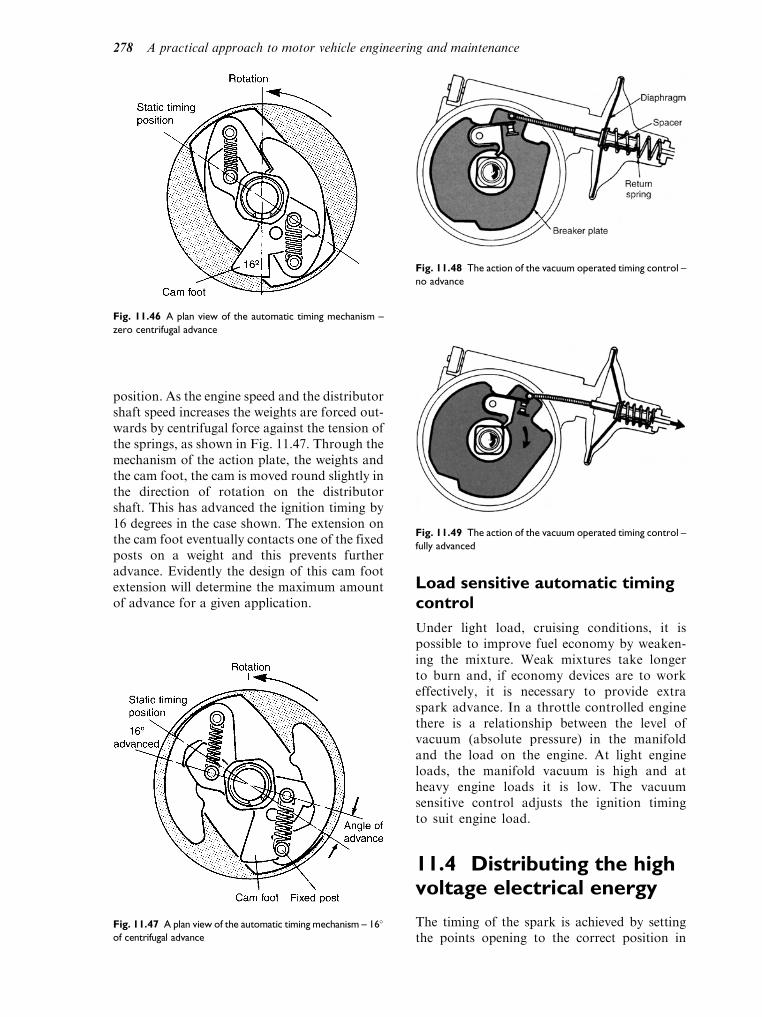
position. As the engine speed and the distributorshaft speed increases the weights are forced out-wards by centrifugal force against the tension ofthe springs, as shown in Fig. 11.47. Through themechanism of the action plate, the weights andthe cam foot, the cam is moved round slightly inthe direction of rotation on the distributorshaft. This has advanced the ignition timing by16 degrees in the case shown. The extension onthe cam foot eventually contacts one of the fixedposts on a weight and this prevents furtheradvance. Evidently the design of this cam footextension will determine the maximum amountof advance for a given application.
Load sensitive automatic timingcontrol
Under light load, cruising conditions, it ispossible to improve fuel economy by weaken-ing the mixture. Weak mixtures take longerto burn and, if economy devices are to workeffectively, it is necessary to provide extraspark advance. In a throttle controlled enginethere is a relationship between the level ofvacuum (absolute pressure) in the manifoldand the load on the engine. At light engineloads, the manifold vacuum is high and atheavy engine loads it is low. The vacuumsensitive control adjusts the ignition timingto suit engine load.
11.4 Distributing the highvoltage electrical energy
The timing of the spark is achieved by settingthe points opening to the correct position in
Fig. 11.46 A plan view of the automatic timing mechanism –
zero centrifugal advance
Fig. 11.47 A plan view of the automatic timing mechanism – 16
of centrifugal advance
Fig. 11.48 The action of the vacuum operated timing control –
no advance
Fig. 11.49 The action of the vacuum operated timing control –
fully advanced
278 A practical approach to motor vehicle engineering and maintenance

relation to crank and piston position, or therotor in a rotary engine such as the Wankelengine. Distributing the resultant high voltageelectricity to produce the spark at the requiredcylinder is achieved through the medium of therotor arm and the distributor cap, as shown inFig. 11.50.
In Fig. 11.50, a spring loaded carbon brush issituated beneath the king lead (the one from thecoil). This carbon brush makes contact with themetal part of the rotor and the high voltagecurrent is then passed from the rotor via an airgap to the plug lead electrode and, from therethrough an HT lead to the correct sparkingplug.
The rotor arm shown in Fig. 11.51 is typicalof the type in common usage. It is sometimes thecase that the metal nose of the rotor is extended,as shown in Fig. 11.52. This is intended as anaid to prevent the engine running backwards bymaking the spark occur in a cylinder where thepiston is near bottom dead centre, should theengine start to rotate backwards.
Note the slot above the cam. Inside the rotorarm, in the insulating plastic, is a protrusion
which locates the rotor arm in the slot on thedistributor cam. The rotor is thus driven roundby the distributor cam. The HT leads arearranged in the cap so that they are encounteredin the correct firing sequence, for example, 1 342for a 4 cylinder and probably 153 624 for a 6cylinder in-line engine.
11.5 Cold starting
When an engine is cold the lubricating oil in theengine is more viscous than when it is hot. Thisrequires greater torque from the starting motorand this, in turn, places a greater drain on thebattery.Fig. 11.50 The HT circuit inside the distributor cap
Fig. 11.51 Typical four-/six-cylinder rotor arm and cams
Fig. 11.52 The extended metal nose
Ignition systems 279

Figure 11.53 shows how the voltage requiredto produce a spark at the spark plug gap varieswith temperature. The decimal figures refer to 3different sparking plug gaps. A much higher
voltage is required for cold temperatures.One of the factors that sometimes make an
engine more difficult to start is when it is coldrather than hot. To ease this problem, coil igni-tion systems are often designed to give a morepowerful spark for starting up than is used fornormal running. This process is achieved by theuse of a ballast resistor and a coil that givesnormal operating voltage at a voltage value lower
that the battery voltage, for example, an 8 voltcoil in a 12 volt system. Under running condi-tions the coil operates on current supplied fromthe ignition switch through the ballast resistor tothe primary winding. The size of the ballast resis-tor, in Ohms, is that which produces the desiredoperating voltage for the coil. Under startingconditions the ballast resistor is by-passed andthe coil is supplied with full battery voltage. Thisgives a higher voltage spark for starting purposes.
Figure 11.54 shows the circuit for a ballastedignition system. In this system the ballast resis-tor is a separate component but some othersystems use a length of resistance cable betweenthe ignition switch and the coil, which achievesthe same result. Whichever type of ballast resis-tor is used, its function will be the same, which isto produce a voltage drop that will give the coilits correct operating voltage. If the coil operatesat 8 volts, and the battery voltage is 12 volts,the ballast resistor will provide a voltage dropof 4 volts.
11.6 Sparking plugs
The sparking plug is the means of introducingthe spark into the combustion chamber of inter-nal combustion engines.Fig. 11.53 Spark voltage and plug temperature
Fig. 11.54 A ballasted (series resistor) ignition circuit
280 A practical approach to motor vehicle engineering and maintenance

Figure 11.55 shows details of a widely usedmake of sparking plug. In order to functioneffectively, sparking plugs must operate over awide range of varying conditions. These condi-tions are considered next, together with somefeatures of sparking plug design.
Compression pressure
The voltage required to provide a spark at theplug gap is affected by the pressure in the com-bustion chamber. It is approximately a linearrelationship, as shown in Fig. 11.56. Note thatthe higher the compression pressure, the higherthe voltage required to produce a spark.
The spark gap (electrode gap)
An optimum gap width must be maintained.If the gap is too small the spark energy maybe inadequate for combustion. If the gap is
too wide it may cause the spark to fail underpressure. Both the centre electrode and theearth electrode are made to withstand sparkerosion and chemical corrosion arising fromcombustion. To achieve these aims, theelectrodes are made from a nickel alloy, thecomposition of which is varied to suit parti-cular plug types. For some special applica-tions, the alloys used for the electrodes maycontain rarer metals such as silver, platinumand palladium.
Figure 11.57 shows the spark gap on a new plug.In time the electrodes will wear and thismeans thatspark plugs should be examined at regular inter-vals. The type of electrodewear thatmight occur inuse is shown in Fig. 11.58. The shape of wornelectrodes varies. Small amounts of wear can beremedied by bending the side electrode to give therequired gap but, in cases of excessive wear, theonly remedy is to replace the plug.
For good performance the spark pluginsulator tip must operate in the rangefrom approximately 350 C to 1050 C. If theinsulator tip is too hot, rapid electrode wear willoccur and pre-ignition may also be caused. Ifthe insulator tip is too cool, the plug will ‘foul’
Fig. 11.55 Sparking plug construction
Fig. 11.56 Variation of sparking voltage with compression
pressure Fig. 11.57 The spark plug electrodes gap
Ignition systems 281

and misfiring will occur. The heat range of thespark plug is important in this respect.
Heat range of sparking plugs
Figure 11.59 shows the approximate amounts ofheat energy that are dissipated through the var-ious parts of the spark plug, by far the greatestamount passes through the threaded portioninto the metal of the engine.
A factor that affects the dissipation of heataway from the centre electrode and the insulatornose, is the amount of insulator that is incontact with the metallic part of the plug. Thisis known as the heat path. Spark plugs that ‘run’hot have a long heat path, and spark plugs that‘run’ cold have a short heat path, as shown inFig. 11.60.
In general, hot running plugs are used in coldrunning engines, and cold running plugs areused in hot running engines. The type of plugto be used in a particular engine is specified bythe manufacturer. This recommendation shouldbe observed. In order not to restrict choice, it ispossible to obtain charts which give informationabout other makers plugs that are equivalent toa particular type.
Plug reach
The length of the thread, shown as dimension Rin Fig. 11.55, is a critical dimension. If the cor-rect type of plug is fitted to a particular engine,there should be no problem and the plug willseat, as shown in Fig. 11.61.
However, if the reach is too long, the electro-des and threaded part of the plug will protrudeinto the combustion chamber and will probablydamage the valves and piston.
Gasket or tapered seat
Spark plugs will be found with a gasket typeseat, as shown in Fig. 11.62, or a tapered seat,as shown in Fig. 11.63.
Gasket seat
Spark plugs with a gasket type seat need to beinstalled ‘finger tight’ until the gasket is firmlyon to its seat. Having previously ensured thatthe seat is clean, the final tightening should be tothe engine maker’s recommended torque.
Fig. 11.58 Worn electrodes
Fig. 11.59 The heat flow in a typical sparking plug
Fig. 11.60 The heat path
282 A practical approach to motor vehicle engineering and maintenance
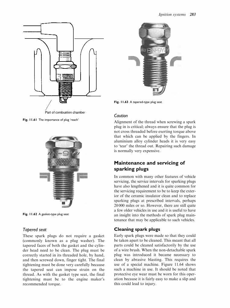
Tapered seat
These spark plugs do not require a gasket(commonly known as a plug washer). Thetapered faces of both the gasket and the cylin-der head need to be clean. The plug must becorrectly started in its threaded hole, by hand,and then screwed down, finger tight. The finaltightening must be done very carefully becausethe tapered seat can impose strain on thethread. As with the gasket type seat, the finaltightening must be to the engine maker’srecommended torque.
Caution
Alignment of the thread when screwing a sparkplug in is critical; always ensure that the plug isnot cross threaded before exerting torque abovethat which can be applied by the fingers. Inaluminium alloy cylinder heads it is very easyto ‘tear’ the thread out. Repairing such damageis normally very expensive.
Maintenance and servicing ofsparking plugs
In common with many other features of vehicleservicing, the service intervals for sparking plugshave also lengthened and it is quite common forthe servicing requirement to be to keep the exter-ior of the ceramic insulator clean and to replacesparking plugs at prescribed intervals, perhaps20 000 miles or so. However, there are still quitea few older vehicles in use and it is useful to havean insight into the methods of spark plug main-tenance that may be applicable to such vehicles.
Cleaning spark plugs
Early spark plugs were made so that they couldbe taken apart to be cleaned. This meant that allparts could be cleaned satisfactorily by the useof a wire brush. When the non-detachable sparkplug was introduced it became necessary toclean by abrasive blasting. This requires theuse of a special machine. Figure 11.64 showssuch a machine in use. It should be noted thatprotective eye wear must be worn for this oper-ation because it is fairly easy to make a slip andthis could lead to injury.
Fig. 11.61 The importance of plug ‘reach’
Fig. 11.62 A gasket-type plug seat
Fig. 11.63 A tapered-type plug seat
Ignition systems 283
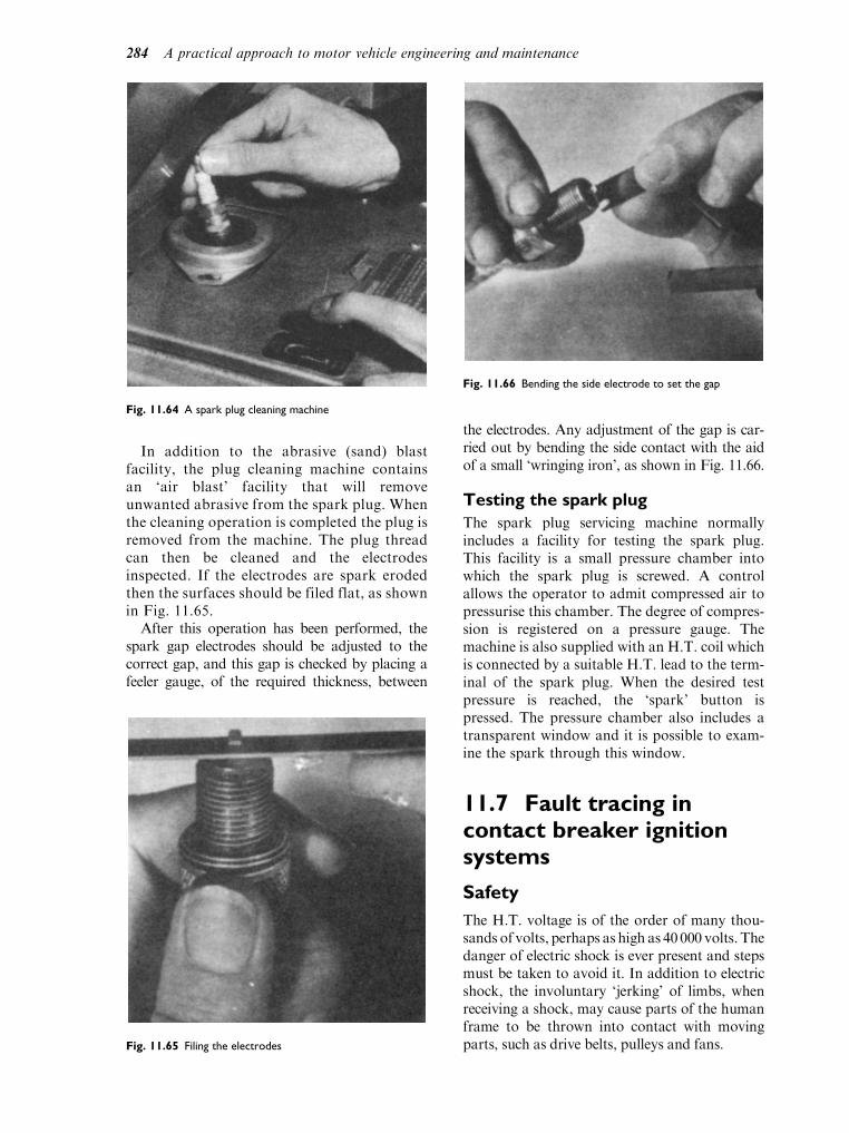
In addition to the abrasive (sand) blastfacility, the plug cleaning machine containsan ‘air blast’ facility that will removeunwanted abrasive from the spark plug. Whenthe cleaning operation is completed the plug isremoved from the machine. The plug threadcan then be cleaned and the electrodesinspected. If the electrodes are spark erodedthen the surfaces should be filed flat, as shownin Fig. 11.65.
After this operation has been performed, thespark gap electrodes should be adjusted to thecorrect gap, and this gap is checked by placing afeeler gauge, of the required thickness, between
the electrodes. Any adjustment of the gap is car-ried out by bending the side contact with the aidof a small ‘wringing iron’, as shown in Fig. 11.66.
Testing the spark plug
The spark plug servicing machine normallyincludes a facility for testing the spark plug.This facility is a small pressure chamber intowhich the spark plug is screwed. A controlallows the operator to admit compressed air topressurise this chamber. The degree of compres-sion is registered on a pressure gauge. Themachine is also supplied with an H.T. coil whichis connected by a suitable H.T. lead to the term-inal of the spark plug. When the desired testpressure is reached, the ‘spark’ button ispressed. The pressure chamber also includes atransparent window and it is possible to exam-ine the spark through this window.
11.7 Fault tracing incontact breaker ignitionsystems
Safety
The H.T. voltage is of the order of many thou-sands of volts, perhaps as high as 40 000 volts. Thedanger of electric shock is ever present and stepsmust be taken to avoid it. In addition to electricshock, the involuntary ‘jerking’ of limbs, whenreceiving a shock, may cause parts of the humanframe to be thrown into contact with movingparts, such as drive belts, pulleys and fans.
Fig. 11.64 A spark plug cleaning machine
Fig. 11.65 Filing the electrodes
Fig. 11.66 Bending the side electrode to set the gap
284 A practical approach to motor vehicle engineering and maintenance

Care must always be taken to avoid receivingan electric shock. It is possible to obtain specialelectrically insulated tongs for handling H.T.cables when it is necessary to handle the cablesof running engines.
Most of the details about oscilloscope testingof electronic ignition systems also apply to con-tact breaker systems. The details in this sectionrefer to a more practical type of work that maybe required when repairs are required outside aworkshop, as may happen in the case of a road-side breakdown.
Fault finding principles
Before considering ignition system faults and howto deal with them, it is wise to remember thatmuch of the skill required to perform diagnosisand repair of electrical and electronic systems isthe same as that which is required for good-qualitywork of any type. It is important to be methodicaland unwise to start testing things randomly, oreven to try changing parts in the hope that youmight hit on the right thing by chance.
Many people do work methodically andthey probably employ a method similar to the‘Six Step Approach’, which is a good, common-sense approach to problem solving in general.The six step approach provides a good startingreference, although it requires some refinementwhen used for diagnosis of vehicle systems.
We will briefly consider the six steps and at alater stage take into account the refinements thatare considered necessary for vehicle systems.
The ‘six step approach’
This six step approach may be generally recog-nised as an organised approach to problemsolving. As quoted here, it may be seen thatcertain steps are recursive. Therefore it may benecessary to refer back to previous steps as oneproceeds to a solution. Nevertheless, it doesprovide a proven method of ensuring that vitalsteps are not omitted in the fault tracing andrectification process. The six steps are:
1. Collect evidence.2. If it appears to be a flat battery, what checks
can be applied, for example, switch on theheadlamps.
3. Assume that it is a flat battery.4. What caused the battery to become discharged?5. Assume, in this case, that the side and
tail lights had been left on. So, in this case,
re-charging the battery would probably curethe fault.
6. Testing the system would, in this case, prob-ably amount to ensuring that the vehiclestarted promptly with the recharged battery.However, further checks might be applied toensure that there was not some permanentcurrent drain from the battery.
We hope that you will agree that these are good,commonsense steps to take and we feel surethat most readers will recognise that these stepsbear some resemblance to their own method ofworking.
Visual checks
Figure 11.67 shows a preliminary check of thetype that is advised in most approaches tofault tracing. Here the technician is lookingfor any obvious external signs of problems,such as loose connections or broken wires,cracked or damaged H.T. cables, dirty orcracked distributor cap and coil towerinsulator and dirty and damaged spark pluginsulators.
Checking for H.T. sparking
A suitable neon test lamp is useful for this pur-pose. However, Fig. 11.68 shows the king leadremoved from the top of the distributor. Here, itis held 6mm from a suitable earth point. Theengine is then switched on and the starter motoroperated and there should then be a regularhealthy spark each time the C.B. points open.A regular spark in this test shows that the coiland L.T. circuits are working properly and thatthe fault lies in the H.T system, i.e., the rotorarm, the distributor cap, the H.T. leads or thespark plugs.
Fig. 11.67 Performing a visual check
Ignition systems 285

Checking the rotor
The rotor arm can be checked by the procedureshown in Fig. 11.69. Here the distributor capend of the king lead is removed from the dis-tributor cap. The end of the king lead is heldabout 3mm above the metal part of the rotor.With the C.B. points closed and the ignitionswitched on the points can be flicked open witha suitable insulated screwdriver, or an assistantcan be used to turn the engine over on thestarter motor. There should be no spark. If thereis a spark, it means that the rotor insulation hasbroken down and means that the rotor must bereplaced by a new one.
If there is no spark, then this indicates that therotor is satisfactory. The next step would be tocheck the H.T. leads. If, as is likely, they areresistive leads, it will be necessary to look upthe permitted resistance of the leads before per-forming an ohm-meter test. The resistance valuemust fall within the stated limits. If they are notresistive leads, a straightforward continuity testwill prove the conductivity of the H.T. leads. Ifthese checks prove satisfactory, the sparkingplugs must be examined. I have already describedthe procedure for checking sparkingplugs.
If these facilities are not available, the only solu-tion may be to inspect the plugs internally, andthe most likely step will be to fit a new set ofspark plugs. It is unusual to find that a set ofspark plugs has failed completely.
Checking the condition of thecontact points
Should the first test (Fig. 11.68) have failed, i.e., nospark, it is advisable to check the contact breakercondition. The contact surfaces should be cleanand not badly pitted and piled, and the gap shouldbe checked to ensure that it is within the recom-mended limits. The securing screws should bechecked for tightness and there should be no evi-dence of fouling of cables inside the distributor. Ifthe points are badly worn and burnt, a new set ofcontacts should be fitted. After this, the first checkfor H.T. spark should be repeated. If this is suc-cessful then there may be no need to proceedfurther. However, if there is still no spark, furthertests will be required. These tests are nowdescribed. The distributor cap should be removedand the engine rotated, with the ignition off, untilthe C.B. points are closed. The voltmeter is thenconnected between the switch side of the coil andearth. The ignition should then be switched on.The voltmeter should then read battery voltage(very closely) or, if it is a ballasted coil, a lowervoltage, probably 6 to 8 volts.
Checking the voltage on the C.B.side of the coil
If these tests are satisfactory, the next step is toproceed to check the voltage at the contactbreaker side of the coil. The voltmeter positionfor this test is shown in Fig. 11.71.
The C.B. contacts must be open. The voltmeteris then connected between the C.B. terminal of thecoil and earth. The ignition should now beswitched on and the voltmeter reading observed.If the coil primary circuit is satisfactory, a readingthat is very close to that obtained in the test shownin Fig. 11.70 should be seen. If the reading iscorrect, proceed to test the voltage at the coilC.B. terminal with the contact points closed.
If the voltage reading is zero, disconnect theL.T. lead to the distributor. The voltmeter shouldnow read the same voltage as on the switch side ofthe coil. If it still reads zero, it indicates that thereis a broken circuit in the primary side of the coiland this calls for a new coil.
Fig. 11.68 Checking for H.T sparking
Fig. 11.69 Checking the insulation of the rotor
286 A practical approach to motor vehicle engineering and maintenance

Voltage at the C.B. terminal of thecoil – point closed
This test checks the condition of the contactpoints and also checks whether there are anycurrent leakages to earth. The voltmeter shouldshow a zero reading if all is correct, or less than0.2 volts if it is a very sensitive meter. If thereading is more than zero volts, the contactsshould be checked to see if they are clean andproperly closed; the insulation on the contact tocondenser lead and on the L.T. lead should alsobe checked. If these are in order, it may be thatthe capacitor itself is providing a leakage pathto earth.
Testing the capacitor
Now that the H.T. lead has been proved, and ifthere is still no spark from this test, then thecapacitor should be tested.
Figure 11.73 shows how a test capacitor canbe temporarily connected to perform this test.The original capacitor is unscrewed and liftedaway so that its casing does not make contactwith earth. A test capacitor, with suitable cro-codile clips and leads, is then connected, asshown. The ignition is switched on again andthe engine turned over, on the starter motor. If aspark is obtained, this is convincing evidencethat the capacitor should be renewed. If thereis still no spark after proving the capacitor, thecoil should be replaced.
Checking the electrical conditionof the ignition coil
The ignition coil can be checked, as shown inFig. 11.74. The secondary winding resistanceshould be high, probably 10 kohms. (Note: Insome ignition coils the secondary winding isearthed. In such cases, the check for secondarywinding resistance would be made between theHT connection and the coil earth.)
The primary winding resistance should be low(the meter needs to be set to a very low Ohmsscale) 0.5 ohms to 1 ohm.
The tests shown here are of a general nat-ure. They do not apply to a specific systemand, as with most other work on vehiclesystems, it is important to have the figuresthat relate to the specific system beingworked on. However, the tests do show thepractical nature of tests that can be appliedwith the aid of a good-quality multi-meter,sound knowledge of circuits and the relevantinformation.
Fig. 11.70 Voltmeter check on coil supply
Fig. 11.71 Voltmeter check on CB side of coil
Fig. 11.72 Voltmeter test for voltage drop across the points Fig. 11.73 Connecting a test capacitor
Ignition systems 287

11.8 High tension (HT)leads
The HT leads are the means by which the highvoltage electrical energy that makes the spark isconducted to the sparking plug. The high voltage,perhaps as high as 40kV, will wish to seek theshortest path to earth. In order to prevent HTleakage from the cables, they must be heavilyinsulated electrically. The insulating material mustalso be resistant to heat and to oil, water and anycorrosive agents that they may encounter. PVC isoften used for the insulation, because it possessesmost of these properties. To reduce radio inter-ference, the conducting parts of HT leads aremade to have electrical resistance. This resistancecan change in use andHT leads should be checkedto ensure that the leads have the correct resistance.The resistance of HT leads varies considerably, arough guide being 18000ohms per metre length.This means that an HT cable of 300mm length
would have a resistance of 5 400ohms. It is a valuethat can be checked by means of an ohm-meterand the resistance values and tolerances will begiven in the workshop manual.
As with any electric current in a conductor,the HT leads set up a magnetic field. In order toprevent one HT cable inducing current in aneighbouring one, by mutual induction, cablerouting, as arranged by the vehicle manufac-turer, should always be adhered to.
11.9 Some practicalapplications, i.e., doing thejob
A substantial amount of background theory hasbeen covered and we have shown how thistheory is used to make vehicle systems work.When systems break down or cease to function
Fig. 11.74 Checking the HT coil
288 A practical approach to motor vehicle engineering and maintenance

correctly, it is the job of the vehicle service andrepair technician to find out what is wrong andto put it right and this is where practical skill, orcompetence, comes in to play. In a book of thistype, it is not possible to cover every type ofvehicle system and we will not attempt to do so.As with all work, proper safe working practicesmust be observed. Personal safety and the safetyof others nearby must be protected, and thevehicle itself must be protected against damage,by ensuring that the correct procedures pre-scribed by the manufacturer are followed andthat wing and upholstery covers, etc. are used.
Because of the global (international) natureof the vehicle industry, vehicle technicians willencounter a range of products and it is unwiseto attempt even simple work without having agood knowledge of the product, or access tothe information and data relating to the vehicleand system to be worked on.
The practical work described in this sectiongenerally relates to a specific product and that ismade clear in the text. However, the deviceschosen and the work described have beenselected because they highlight types of practicalprocedures and tests that can be applied acrossa range of vehicles. It is intended that this bookshould be used in conjunction with courses ofpractical instruction and learning on the job.
The main source of information and guidanceabout repair and maintenance procedures is themanufacturers workshop manual which is oftenavailable on CDROM.
Ignition timing
Because ignition timing varies with enginespeed, it is necessary to check both the statictiming and the dynamic timing.
Static timing
The following list shows a the ignition timingdetails for a 4 cylinder in-line engine.
Firing order 1 3 4 2. Static advance 10.Contact breaker gap 0.40mm
Dwell angle 55.
For static advance setting, the figures ofinterest are the static advance angle of 10, thecontact breaker gap of 0.40mm and the firingorder.
When re-setting the static timing after per-forming work on the engine, such as on removingand refitting the distributor, it is necessary to
ensure that the piston in the cylinder used fortiming (usually number 1) is on the compressionstroke. The firing order helps here, because in thiscase the valves on number 4 cylinder will be‘rocking’ when number 1 piston is at top deadcentre (TDC) on the compression stroke. The10 static advance tells us that the contact breakerpoints must start to open at 10 before TDC.Engines normally carry timing marks on thecrankshaft pulley and these are made to alignwith a pointer on the engine block, or timing case,as shown in Fig. 11.75.
To position the piston at 10 before TDC, thecrank should be rotated by a spanner on thecrankshaft pulley nut, in the direction of rota-tion of the engine. This ensures that any ‘freeplay’ in the timing gears is taken up. To makethe task more manageable, it is probably wise toremove the sparking plugs. If the alignment ismissed the first time round, the crank shouldcontinue to be rotated in the direction of rota-tion until the piston is on the correct stroke andthe timing marks are correctly aligned.
When the piston position of number 1 cylin-der is accurately set, the distributor should bereplaced with the rotor pointing towards the HTsegment, in the distributor cap, that is normallyconnected to number 1 sparking plug. This pro-cess is made easier on those distributors thathave an off-set coupling.
Setting the timing
The contact breaker gap should be set to thecorrect value and the distributor clamp loo-sened. When the low tension terminal of thedistributor has been re-connected to the coil,a timing light may then be connected between
Fig. 11.75 Engine timing marks
Ignition systems 289

the contact breaker terminal of the coil andearth. With the ignition switched on and thecontact breaker points closed, the timinglamp will be out. When the points open, theprimary current will flow through the timinglight which will light up. An alternative is todisconnect both coil LT connections and thenconnect the timing light in series, as shown inFig. 11.76. In this case the timing light will beon when the points are closed, and off whenthey are open.
When the correct setting has been achieved,the distributor clamp should be tightened,the timing light removed and all leads re-con-nected. The timing light (lamp) can be a lightbulb of suitable voltage (12V) mounted in aholder and fitted with two leads to whichsmall crocodile clips have been securelyattached.
Dynamic timing
As the name suggests, dynamic timing meanschecking the timing with the engine running.At this present level of study we will restrictourselves to the use of the stroboscopic timinglamp, often referred to as a strobe lamp. Thestrobe lamp ‘flash’ is triggered by the H.T. pulsefrom a sparking plug, usually number one cylin-der. When the strobe light is directed on to thetiming marks, the impression is given that themark on the rotating pulley is stationary inrelation to the fixed timing mark.
Safety note
This useful stroboscopic effect carries with it
potential danger because the impression is
given that other rotating parts, such as fan
blades, drive belts, etc., are also stationary. It
is therefore important not to allow hair and
clothing or any part of the body to come into
contact with moving parts. It is also important
to avoid electric shock. As with other work
that involves running engines, exhaust extrac-
tion equipment should be used.
Checking the static timing withthe engine running
The static timing setting can be checked bymeansof the strobe lamp because, at idling speed, thecentrifugal advance and the vacuum advancemechanisms should not be adding to the staticadvance angle. The static timing mark on theengine should be highlighted with white chalk orsome other suitable marking substance. This willenable you to locate the correct marks whenconducting the test. Figure 11.77 shows the strobelight, this one incorporating an advance meter,being used to check the static timing. For this test,the engine will be run at the manufacturer’srecommended speed, probably idling speed. Ifthe marks align correctly, no further action isrequired.However, if themarks do not align, thenthe distributor clamp must be slackened and thedistributor body rotated until the marks are
Fig. 11.76 Using a timing light
290 A practical approach to motor vehicle engineering and maintenance

aligned correctly. When the correct alignment isachieved, the clamp must be re-tightened.
Checking the centrifugal advancemechanism
The timing details that we are using as an exam-ple gave us a static advance figure of 10 and thefollowing for vacuum and centrifugal.
Automatic centrifugal advance 25
Vacuum advance 12
If the vacuum advance is disabled by discon-necting the pipe at the engine end, and blankingoff the hole with a suitable device, the maximumamount of advance obtainable will be 35, thatis 25 from the centrifugal device and 10 static.In this example this maximum advance occursat 4 300 rev/min of the engine and a tachometer(rev counter) will be needed to record the enginespeed. With the vacuum pipe disconnected, thetachometer and strobe light connected, and allleads checked to ensure that nothing is touchingmoving parts, or hot exhausts, the check mayproceed. It will probably require another personto operate the accelerator and observe the tach-ometer. The strobe light should be aimed at thetiming marks and when the engine is brought upto the correct speed, the control on the advancemeter is adjusted until the timing marksalign. The number of degrees shown onthe advance meter should then show themaximum advance angle. If this is correct, thevacuum advance mechanism can be tested.
Checking the vacuum advancemechanism
After removing the blanking device, the vacuumpipe should be re-connected and the enginespeed will increase slightly if the vacuum deviceis working.
Dwell angle
In contact breaker type ignition systems,the dwell angle is the period during whichthe contact breaker points are closed. Thedwell angle is the period during whichthe electrical energy builds up in the coilprimary winding. If the dwell period is tooshort, the primary current will not reachits maximum value and the H.T. sparkwill be accordingly weaker. Figure 11.78shows dwell angle, which has already beendiscussed in the context of the operatingprinciples of the ignition system.
On a four lobed cam, as shown here, the dwellangle is 54 þ or 5. However, the dwell anglevaries according to distributor type and themanufacturer’s data should always be checkedto ensure that the correct figure is being used.The dwell angle is affected by the points gap. Ifthe gap is too large, the heel of the movingcontact will be closer to the cam and this willcause the dwell angle to be smaller than itshould be (Fig. 11.79).
Fig. 11.77 The stroboscopic timing lamp
Fig. 11.78 Dwell angle
Ignition systems 291
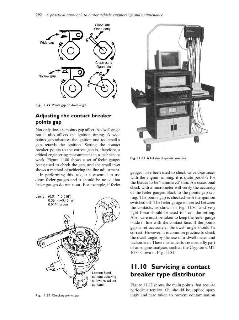
Adjusting the contact breakerpoints gap
Not only does the points gap affect the dwell anglebut it also affects the ignition timing. A widepoints gap advances the ignition and too small agap retards the ignition. Setting the contactbreaker points to the correct gap is, therefore, acritical engineering measurement in a technicianswork. Figure 11.80 shows a set of feeler gaugesbeing used to check the gap, and the small insetshows a method of achieving the fine adjustment.
In performing this task, it is essential to useclean feeler gauges and it should be noted thatfeeler gauges do wear out. For example, if feeler
gauges have been used to check valve clearanceswith the engine running, it is quite possible forthe blades to be ‘hammered’ thin. An occasionalcheck with a micrometer will verify the accuracyof the feeler gauges. Back to the points gap set-ting. The points gap is checked with the ignitionswitched off. The feeler gauge is inserted betweenthe contacts, as shown in Fig. 11.80, and verylight force should be used to ‘feel’ the setting.Also, care must be taken to keep the feeler gaugeblade in line with the contact face. If the pointsgap is set accurately, the dwell angle should becorrect. However, it is common practice to checkthe dwell angle by the use of a dwell meter andtachometer. These instruments are normally partof an engine analyser, such as the Crypton CMT1000 shown in Fig. 11.81.
11.10 Servicing a contactbreaker type distributor
Figure 11.82 shows the main points that requireperiodic attention. Oil should be applied spar-ingly and care taken to prevent contamination
Fig. 11.79 Points gap on dwell angle
Fig. 11.80 Checking points gap
Fig. 11.81 A full size diagnostic machine
292 A practical approach to motor vehicle engineering and maintenance

of the contact points. While the distributor capis removed it should be wiped clean, inside andout, and checked for signs of damage and track-ing (H.T. leakage). The rotor arm should also beinspected.
11.11 Explanation of termsassociated with ignitionsystems
Misfiring
Misfiring is a term that is normally applied to thetype of defect that shows up as an occasional lossof spark on one or more cylinders. It can becaused by almost any part of the ignition systemand the cause is often difficult to locate. Muchdepends on the way in which the fault occurs. Ifit is a regular and constant misfire one could startby checking for H.T. at each sparking plug. Ifeach plug is receiving H.T., then the most likelycause is a spark plug. Plugs should then beremoved and tested. In some cases, where theengine has not been running for very long, theinsulator of a non-firing spark plug will be sig-nificantly cooler to the touch than the other pluginsulators. This may help in locating the misfire.Here again, an electronic engine analyser is muchmore satisfactory, because a power drop test willshow which cylinder is not firing.
Cutting out
Cutting out is a term that is used to describe thetype of fault where the engine stops completely,
perhaps only for a split second. The most likelycause here is that there is a broken or looseconnection that breaks the circuit momentarily.Careful examination of all connections and‘wiggling’ of cables whilst conducting a voltagedrop test across the connectors, should help tolocate such faults.
Hesitation
This normally happens under acceleration andthe symptoms are that the engine does notrespond to throttle operation and can causeproblems when overtaking. The voltagerequired to produce a spark rises with the loadplaced on the engine as happens under acceler-ation, and probable causes are wide spark pluggaps or spark plugs breaking down under load.
Excessive fuel consumption
Incorrect ignition timing is usually associatedwith high fuel consumption.
Low power
Incorrect ignition timing, weak spark and dirtyor badly adjusted plugs are defects associatedwith low power.
Overheating
The ignition defect most often associated withoverheating is the ignition timing, but otherdefects that cause pre-ignition and detonationcan also lead to overheating of the engine.
Running on
This happens when the engine continues to run,even after the ignition is switched off. Anobvious cause is that parts of the engine interiorremain sufficiently hot to cause combustion.This may be caused by a dirty engine, withheavy carbon deposits in the combustion cham-ber and dirty, worn or incorrect type of spark-ing plugs. It is overcome to some extent byfitting a cut-off valve in the engine idling system.This prevents mixture from entering the com-bustion chamber through the engine idling sys-tem. This is the probable source of fuelling asthe throttle is virtually closed.
Detonation and pre-ignition
Both detonation and pre-ignition give rise to aknocking sound which, at times, can be quiteviolent. On other occasions, a high pitched‘pinking’ sound may be heard and, as the term
Fig. 11.82 Service details for a distributor
Ignition systems 293

implies, this sound is known as pinking. Pre-ignition arises when combustion happens beforethe spark occurs. Detonation happens after thespark has occurred.
Pre-ignition
Pre-ignition may be caused by ‘hot’ spots inthe combustion space. These hot spots may becaused by sharp edges and rough metallic sur-faces, glowing deposits (carbon), overheatedspark plugs or badly seated valves. As a resultof ignition starting before the spark occurs, thepressure and temperature in the cylinder rise tohigh levels at the wrong time. This gives rise topoor performance, engine knock, and eventualengine damage. Some of the probable causes ofpre-ignition are listed below.
Probable causes of pre-ignition
Sharp edges and rough metallic surfaces
These are likely to be caused by manufactur-ing defects and they are normally rectified atthat stage. However, if an engine has beenopened up for repair work it is possible thatcareless use of tools may damage a surface.Should this be the case, the remedy wouldbe to remove the roughness by means of ascraper, a file or a burr.
Glowing deposits (carbon)
This is most likely to occur in an engine that hascovered a high mileage. Decarbonising the engine(a decoke) would probably be the answer here.
Overheated spark plugs
In this case there are various factors to consider,such as:
. Are the spark plugs of the correct type andheat range?
. Are the spark plugs clean?
. Are the electrodes worn thin?
Badly seated valves
If a poppet type valve does not seat properly, itis possible for part of the valve head to form ahot spot. Failure to seat squarely could becaused by a bent valve, a misaligned valve guideand, in the case of older engines, a badly recon-ditioned valve. In each case the remedy wouldbe to rectify the fault indicated.
In addition to the above defects combus-tion knock can arise from use of the incorrectfuel. The Octane rating of a fuel is the critical
factor here. Tetra-ethyl lead (leaded fuel)used to be the method of altering the octanerating (anti-knock value) of petroleum spirit.But now that most spark ignition engines arefitted with catalytic convertors for emissionscontrol, leaded fuels cannot be used. Thereare different octane grades of unleaded fueland many electronically controlled enginesare provided with a simple means of alteringsettings if a driver wishes to use a differentoctane rating fuel from the one that she/hehas been using.
We hope that you will agree that these aregood, commonsense steps to take and we feelsure that most readers will recognise that thesesteps bear some resemblance to their ownmethod of working.
In the following cases it is assumed that theabove steps have been followed and that the faulthas been found to exist in the area of the ignitionsystem.
Poor starting or failure to start
For current purposes we will assume that thefuel and electrical systems are in good order.In particular, that the battery is fully chargedand that the starter motor is capable of rotatingthe engine correctly. We shall also assume thatthe mechanical condition of the engine is goodand that the fault has been identified as being inthe area of the ignition system.
Poor starting
If the controls are operated correctly, the engineshould start promptly. The time taken to startup may vary with air temperature. For example,when it is very cold the cranking speed ofthe engine will be affected by the viscosity ofthe lubricating oil, and the mixture entering theengine is affected by contact with cold surfaces.Generally, an engine will start more promptlywhen it has warmed up than it will when cold.
For ‘poor’ starting we are, therefore, lookingat cases where, taking account of the abovefactors, the engine either takes a long time tostart or is reluctant to start at all.
The ignition system faults that have a bearingon the problem of poor starting are:
(a) Weak spark
This could be caused by loss of electricalenergy in the ignition circuit or failure togenerate sufficient energy for a spark, in thefirst instance.
294 A practical approach to motor vehicle engineering and maintenance

Loss of electrical energy could be due todefective connection and/or defective insu-lation in either the low tension circuit or thehigh tension circuit. A range of tests andchecks that can be carried out, is describedin the section on servicing and repair.
(b) Spark occurring sometimes but not at other
times
This is known as an intermittent fault. Hereagain, the problem could lie in either orboth the L.T. and the H.T. circuits.
(c) Spark occurring at the wrong time
In most cases this means that the ignitiontiming is incorrectly set.
Failure to start
As it is ignition faults that we are considering,the obvious pace to start is the sparking pluggap. Failure to start is probably due to therebeing no spark, or a spark that is too weak tocause combustion. However, if the ignitiontiming is not correct, or the H.T. leads havebeen wrongly connected (not in accordancewith the firing order), the engine may also failto start.
Learning tasks
Do not attempt any practical work until
you have been properly trained. You
must always seek the permission and
advice of your supervisor before you
attempt any of the practical tasks.
Much of NVQ assessment is based on work
that you have actually performed. Each time
you complete the tasks that you will keeping a
record or you should note down the tools and
equipment that you have used.
1. Make a list of the precautions to be taken
when working on ignition systems.
2. Describe the procedure for setting the sta-
tic ignition timing on an engine that has a
contact breaker type ignition system.
3. Give details of the procedure and type of
feeler gauges used to set the pick-up to
rotor air gap in an electronic, contact break-
erless, ignition system.
4. Take a set of ignition H.T. leads and mea-
sure the length in centimetres and the resis-
tance in kOhms of each lead. Compare the
figures with those given in this book or in
the workshop manual for the vehicle. Write
down the result and state whether or not
the leads are in good condition.
5. Examine a set of sparking plugs from an
engine. Measure and record:
(a) the spark gaps
(b) the reach of each plug
(c) the thread diameter
(d) the recommended tightening torque
(e) note the type of spark plug (not the
make) and state whether they are
intended for use in a hot running
engine or a cold running engine.
6. Examine a distributorless ignition system.
Write down the number of ignition coils
and the position of the sensor that triggers
the ignition pulses.
7. Describe, with the aid of diagrams, a
simple practical test that can be used
to check the electrical condition of a
rotor arm.
8. Perform a test to check the electrical
output of a magnetic pulse type generator
that is used in an electronic ignition
system.
9. Obtain an ignition coil and measure the
resistance of the primary winding and the
secondary winding. Record the figures and
compare with the figures given in this
book, then write down your opinion about
the condition of the coil. State whether or
not the coil is for use in a ballasted ignition
system.
10. Describe the procedure for setting up a
garage type oscilloscope to check ignition
coil polarity.
Self assessment questions
1. A Hall effect ignition system sensor:
(a) requires a supply of electricity
(b) generates electricity by electro magnet-
ism
(c) can only be used on ignition systems that
have a distributor
(d) can only be used on 4 cylinder engines
2. In a test on a contact breaker type ignition
system with the points closed and the ignition
switched on, the voltage drop across the points
should be:
(a) 14 volts
(b) not more than 0.2 volts
(c) 2.5 volts
(d) 2 volts
Ignition systems 295

3. In a ‘lost spark’ ignition system each cylinder has
a spark:
(a) on the induction stroke as well as at the end
of the compression stroke
(b) on the exhaust stroke as well as at the end
of the power stroke
(c) twice on the power stroke
(d) on the exhaust stroke as well as at the end
of the compression stroke
4. Ignition related faults that affect the emissions
controls on the vehicle:
(a) cause the MIL lamp to illuminate on EOBD
systems
(b) cause the vehicle to be disabled
(c) require the vehicle to be taken off the road
immediately
(d) should be left to rectify themselves
5. A set of ignition HT leads are required to have a
resistance of 18 k ohms per metre of length.
One of these leads that is 430 mm long will
have a resistance of:
(a) 41.86 ohms
(b) 7740 ohms
(c) 4186 ohms
(d) 0.7 k ohms
6. Sparking plugs that ‘run’ hot have a long
heat path and sparking plugs that ‘run’ cold
have a short heat path. The sparking
plugs fitted to an engine that runs cool would
have:
(a) a short heat path
(b) tapered seats
(c) a long heat path
(d) short reach
7. The ‘firing line’ on an oscilloscope trace of
ignition HT voltage represents:
(a) the high voltage that is needed to cause the
spark to bridge the sparking plug gap
(b) the current in the primary winding of the
ignition coil
(c) the condition of the condenser
(d) the air–fuel ratio of the mixture in the
cylinder
8. A knock sensor is used:
(a) to allow the ECM to alter the ignition timing
(b) to alert the driver to mechanical noise
from wide valve clearances
(c) to allow catalytic converters to operate
on leaded fuel
(d) on contact breaker type ignition systems
only
9. Pre-ignition happens when:
(a) the static ignition timing is too far advanced
(b) combustion occurs before the spark
(c) pressure waves cause a region of high
pressure, in the combustion chamber,
after the spark has occurred
(d) the ignition is retarded
10. In engine management, the ignition timing can
be altered to suit engine wear. When new parts
are fitted to replace worn or damaged ones on
this type of ignition system, the vehicle should:
(a) have a new ECM fitted
(b) be operated under normal running condi-
tions for a length of time that allows the
ECM to adjust to the new parts
(c) be returned to the customer without
advising them that it may take time for
the vehicle to return to its best working
condition
(d) have the entire ignition system renewed
11. The vacuum operated timing control on dis-
tributor type ignition systems:
(a) changes the ignition timing to suit engine
speed
(b) changes the ignition timing to suit engine
temperature
(c) changes the ignition timing to suit load on
the engine
(d) changes the air–fuel ratio
296 A practical approach to motor vehicle engineering and maintenance

12Electrical systems and circuits
Topics covered in thischapter
Central locking
Screen wipers
Vehicle security alarm
Electric windows
Screen washers
Electric mirrors
Vehicle lighting systems
Supplementary restraint systems – airbags and
seatbelt pre-tensioners
12.1 Central door lockingsystems
Manual operation
A central door locking system permits all doors,often including the boot lid or tailgate, to belocked centrally from the driver’s door and,normally includes the front passenger’s dooralso.
The locking and unlocking action is producedby an electro-mechanical device, such as a sole-noid or an electric motor. The door key operatesa switch which controls the electrical supply thatactuates the door lock mechanism and theremote control activates a switching circuit inthe electronic control module (ECM) that alsoactuates the locking mechanism. For safety andconvenience, the interior door handles alsooperate the unlocking mechanism.
Remote operation
The remote control operates in much the sameway as the remote control for a domestic televi-sion. A unique code is transmitted from theremote control which is normally containedin the ignition key. Two types of transmitter
are used, infra-red and radio frequency. Theelectronic control module (ECM) that controlsthe supply of current to the door lock actuatorscontains a sensor that detects infra-red signalsor, in the case of radio frequency systems, anaerial to detect the radio frequency signal. Theremote signal is normally effective over a rangeof several metres. Figure 12.1 shows the generalprinciple of central locking systems.
The remote controller
The encoded signals that are transmitted by theremote controller are produced by electroniccircuits that are energised by a small batterythat is housed in the controller. A pad on thecontroller is pressed for unlocking and anotherpad is pressed for locking purposes. The devicemay also be provided with an LED that indi-cates battery level.
A simple central locking circuit
Both the manual central lock system and theremote central lock systems employ similar cir-cuits and actuators inside the doors. A generaldescription of central locking system circuits, ofthe type shown in Fig. 12.2, should serve to bringabout the necessary level of understanding.
Solenoid
The type of solenoid used in door lockingsystem is shown in Fig. 12.2(a). The flow ofcurrent in one direction causes the doors tolock and when current flows in the oppositedirection the doors are unlocked. The reversalof current is performed by the ECM.
Motor
The motors (Fig. 12.2(b)) used for door lockingsystems are normally of the permanent magnettype because they are capable of being reversedby changing the direction of current flowthrough the motor. The motorised operation isconsidered to be slightly smoother in operation

than in the solenoid system. The reversal ofcurrent flow is achieved through the switchingaction provided by the ECM.
Circuit protection
In addition to a fuse, door locking circuits areoften equipped with a thermal circuit breaker.
Maintenance and fault tracing
The wiring into the doors is flexible and is pro-tected by a weatherproof sheath. The controlrod from the solenoid, or motor, to the mechan-ical door lock is normally enclosed in a sheathto guard against ingress of water or dust. Peri-odic visual inspections of the exterior shouldsuffice for these parts. The external mechanicalparts of the locks should be lubricated with anapproved lubricant whilst ensuring that suchlubricant is applied sparingly and carefully soas not to harm the upholstery.
In the event of a locking system failure, everyattempt to determine the source of the problemshould be made before door trim is removed andwork started on the circuit and mechanism insidethe door trim. It is recommended that manufac-tures’ guides are used because of the considerablevariations that are to be found throughout thevehicles that are in use. Some of the more obviousgeneral points are covered here:
12.2 Screen wipers
Screen wipers are required so that the driver’sability to see out of the vehicle is maintained inall types of conditions. It is a legal requirementthat screen wipers must be maintained in goodworking condition.
Defect Action to be taken
Central locking
fails to operate.
Check remote control battery
Make sure that correct key is
being used. If key is lost, follow
instructions for coding etc that
are normally found in the
driver’s handbook
Check vehicle battery condition
Check fuse, or circuit breaker.
If fuse is blown, check for electrical
Problems. Replace fuse – if fuse
blows again shortly after replacing,
start search
For the cause of the problem.
A single solenoid
or motor does
not operate.
Electrical
Check wiring into the door.
Check operation of solenoid or
motor
Mechanical
Check for broken or seized parts
M M M M
Remote signalreceiver
Power supply
FuseDoor switch
Actuators fordoor locks
Reversible motorsor solenoids
ECM
Fig. 12.1 Block circuit diagram for remote central locking
298 A practical approach to motor vehicle engineering and maintenance

Modern wipers are electrically operated and asingle electric motor normally drives both frontscreen wipers through a mechanical linkage.The principle is shown in Fig. 12.3.
Modern styling of vehicles requires the rearscreen to be fitted with a separate screen
wiper and this is equipped with a separateelectric motor. Permanent magnet motorsare normally used for screen wiper applica-tions because they are compact and powerfuland they are readily equipped with two speedoperation.
Door key(Transmitter + Battery)
Infra red or radio frequencycoded signal
Door lockcontrol (ECK)
Door lock solenoid
Front doorlock solenoid Door key
lock switchRear door
lock solenoid
MotororSolenoid
Two way solenoid
Permanent magnet
Field coil Field coil
Lock
Unlock
Reversible electric motor
Permanentmagnet
Armature
Worm gear
LockUnlock
(a)
(b)
++
Lockwinding
Unlockwinding
Fig. 12.2 A typical remote central locking system
Electrical systems and circuits 299

Operation
The armature shaft of the motor has a worm gearmachined into it and this mates with a wormwheel that provides a gear reduction. The wormwheel carries a crankpin which is connected by arigid link to the screen wiper linkage and, by thismeans, the rotary movement of the worm wheelgear is converted into the reciprocating (to andfro) movement of the wiper linkage. The wiperarms are pivoted near the screen and the shaft onwhich the blade ismounted is connected by a leverto the reciprocating wiper linkage. This results inangular movement of the wiper arm and blade.
Control of the wipers
The control switch for the screenwipers ismountedin a convenient position adjacent to the steeringwheel. The switch is multi-functional because it isused to select the options that are available, inaddition to the basic on off operations.
Parking the wiper blades
When the wipers are not in use, the armsand blades are placed (parked) in a positionthat does not obstruct the view from insidethe vehicle. This operation is automaticallyachieved by the use of a cam operated limitswitch that is located inside the wiper motor
housing. A simplified circuit for this opera-tion is shown in Fig. 12.4.
Regenerative braking
When the wipers are in action, the mechanismpossesses considerable momentum and a form ofelectric braking is utilised the helps to bring thewiper mechanism to rest in the desired positionwithout placing undue strain on it. The circuit inFig. 12.5 shows how the limit switch cam acti-vates an additional set of electrical contacts.
When these contacts are closed, an electricalload is placed across the screen wiper motorarmature and the generator effect of the movingarmature places an effective braking effect onthe wiper motor and causes it to stop in therequired position.
Two speed operation
Permanent magnet screen wiper motorsare capable of operating at two different speedsto suit different weather conditions. The speedvariation is achieved by means of a third brush.This third brush is connected to a smaller num-ber of armature windings than the other mainbrushes and this causes a higher current to flowin the armature coils and this, in turn, leads to ahigher speed of rotation. Figure 12.6 shows thearrangement.
Motor
Worm & wheelreduction gear
Slide block
Linking bar
Wiper blade
Wiper arm
Connecting rod
Fig. 12.3 Screen wiper system
300 A practical approach to motor vehicle engineering and maintenance

Intermittent operation
Most modern wiper systems make provision forthe driver to select a switch position that allowsthe wipers to provide a short spell of wiper
action at set intervals of time. This is achievedby means of a timer circuit that controls a relay.The wipe action usually occurs at intervals of15 to 20 seconds and is designed to help thedriver cope with conditions where light rain orshowers are encountered. In some designs thedelay period may be adjusted at the wiperswitch. In such cases, the timer circuit will con-tain a resistive and capacitive device in whichthe resistance may be altered to vary the inter-val between wipe actions. An outline circuit isshown in Fig. 12.6.
12.3 Screen washers
A windscreen washer on the driver’s side of thevehicle is an essential piece of equipment and itmust be maintained in working order. In addi-tion to this basic requirement, most modernvehicles are equipped with screen wash facilitieson the passenger’s side and the rear screen, andmany vehicles are now equipped with headlampwashers. Figure 12.7 shows the essential parts ofa screen washer systems.
The pump is electrically operated from thescreen wiper switch and it is normallymounted at the base of washer fluid reservoirwhere it is gravity fed. The inlet to the pumpis provided with a filter in order to excludeforeign matter and thus prevent blockagesand damage to the pump. The fluid, under apressure of approximately 0.7 bar from thepump, is conveyed to the washer jets throughplastic piping. The jets are arranged so that amaximum washing effect is gained from thewash-wipe action. The washer should only be
Link
Limit switchWiper motor
Driver’s switch
Arm
CAM on motor shaft
Blade
M
Fig. 12.4 Limit switch circuit for ‘Off’ position of wiper arm
Brakingswitch
Driver’s switch
M
CAM
Earth switch
Fig. 12.5 Regenerative braking
1 GN Fuse
Limit switch
Third brush
Relaytimer
IntLowHigh
Wiper switch
M
Fig. 12.6 Two speed and intermittent wiper control (simplified
circuit)
Electrical systems and circuits 301

operated for a few seconds at a time as longperiods of continuous use may result indamage to the pump motor. A few secondsof use normally suffices for effective cleaningof the screen. The fluid used is water to whichis added an anti-freeze agent, a detergentand an anti-corrosion agent. The strength ofthe washer fluid that is added to the water inthe washer reservoir is varied according to theseason of the year.
Rear screen washer
Figure 12.7 shows how the screen washerreservoir and pump may be connected so thatit supplies both front and rear screens.
A solenoid operated washer valve is placed inthe pipeline and operation of the washer switchpermits the solenoid valve to direct the fluid tothe required washer jets.
Maintenance and repair
It should be evident that preventive maintenanceof wipers and washers is important becausethere may be quite long intervals when theyare not in use and, if it only becomes clear thatthe wipe/wash system is not working properlyduring a journey, an inconvenient and possiblydangerous situation may arise. Maintenance ofscreen wipers is largely a matter of taking pre-ventive measures, such as examining the condi-tion of wiper blades to ensure that they are notworn, perished or hardened and replacing them
as necessary. The action of wipers is readilyobserved by the simple expedient of operatingthem in their various modes of operation, forexample, slow speed, intermittent, etc.
Screen washer fluid levels must be checked atregular intervals and the strength of the washerfluid mixture that is added to the system must beadjusted to suit weather conditions. The washaction may readily be examined by operatingthe system and observing the pattern of fluidsprayed on to the screen through the washerjets. The condition of the fluid reservoir and itsfixings, and the condition of the plastic tubesthat connect the pump outlet to the jets, shouldbe checked to ensure that they are secure and ingood condition.
Repairs and fault tracing
For current purposes, screen wiper defects mayusefully be grouped into two categories namely,1) Electrical, and 2) Mechanical.
Electrical defects
Problem – electrical overload
Possible effect – fuse blown or circuit breakertriggered
Some thermal circuit breakers operate by break-ing the circuit at intervals, in which case thesporadic behaviour of the wipers will indicatethat there is something wrong. Persistent opera-tion of the circuit breaker means that there is aproblem that requires attention because the wiper
Hose
Nozzle
Motor (pump)Tank
Rear washer nozzle
Front washernozzle
Solenoid
To frontwasher
Washer valve
From pump
Valve
To rear washer
Washertank
Fig. 12.7 Front and rear washers screen washers
302 A practical approach to motor vehicle engineering and maintenance

circuit is being overloaded. In the case of a blownfuse, it may be that the fuse has blown becauseof a temporary overload such as ice on the screenor excessively dirty conditions. In this case itwould probably be in order to replace the fuseand perform a full test on the wipers, ensuring aclean and wet screen before attempting any test.Should the fuse blow again, or the circuit breakercome into operation again, the system must beexamined to see whether it is an electrical fault ora mechanical fault.
Electrical overload may arise from a shortcircuit where some part of the wiring hasbecome damaged, or it may arise from frictionin the motor bearing, damage in the linkage, orexcessive pressure on the wiper blades. Mostmanufacturers’ dedicated test equipment makesprovision for electrical tests on wiper circuits. Ingeneral, the wiper current may be checked byplacing an ammeter in series with the motor andthen conducting a test to observe the currentflow. On a 12 volt system, the wiper motoroperating current is approximately 1.5A to4A. The diagrams, in Fig. 12.8, show the posi-tions of the ammeter for conducting currenttests on Lucas-type wiper motors in the lowand high speed modes. The procedure for per-forming such tests varies for different makes ofvehicle and electrical equipment and theyshould only be attempted by skilled personneland in accordance with the manufacturer’sinstructions.
Motor does not operate or motion is weak
Motor
Weak motion of the wipers may arise from avoltage drop in the circuit. Causes may be dirtyor loose connections which may usually bedetected by means of voltage tests at the motorand the switch and suitable intermediate points.The brushes in the motor may be worn and, insome cases, these can be replaced. However, theoverall efficacy and cost of such work must becompared with the alternative of a replacementmotor.
Switch
The control switch may fail completely, or itmay fail to operate some of the wipe/wash func-tions. In the case of complete failure, circuit testsshould be carried out in order to ascertain that itis switch failure and not some other electricalproblem, such as a broken or disconnected wireor a loose connection. Once the cause of the
malfunction has been confirmed as a defectiveswitch, the remedy will probably be to replacethe switch.
Mechanical defects
Blades
Poor wiping action may result from hardened,cracked or perished blades. Before condemningwiper blades the screen should be thoroughlycleaned to remove any traffic film that may havestuck to the screen. The wipers should then beretested with the screen wet. Once satisfied thatthe wiper blades are at fault, it is usually possi-ble to effect a cure by replacing the rubber partof the blades.
Arms
Wiper arms are spring loaded and aredesigned to exert sufficient blade pressure onthe screen to ensure effective wiping action. Ifthe spring tension becomes weak, the bladepressure will be lower and wiping action willbe poor with the possibility of blade chatter-ing. Too great a spring pressure may causescratching of the glass and poor wiper actiondue to extra load on the motor. Most wiperarm problems may be detected by visualexamination and comparison with knowngood examples.
Linkage
Wear in the linkage will result in lost motionat the wiper blades and excessive noise whenthe wipers are in operation. Looseness inthe wiper mechanism may result from theblades not being properly secured to thespindle.
12.4 Anti theft devices
The coded ignition key and engineimmobiliser system
The engine immobiliser system is a theft deter-rent system that is designed to prevent theengine of the vehicle from being started by anyother means than the uniquely coded ignitionkey. The principal parts of a system are shownin Fig. 12.9.
The transponder chip in the handle of theignition key is an integrated circuit that isprogrammed to communicate with the antenna(transponder key coil) that surrounds the barrelof the steering lock. When electromagnetic
Electrical systems and circuits 303

TEST PROCEDURE FOR SCREEN WIPER MOTOR
*Do not disconnect battery supply from plug while the wiper blades are in the parked position.
Note: All tests with screen wet.
CONNECTIONS
Brown/Green All types Motor should run atnormal speed
Motor should run athigh speed
Motor should run topark position then stop
Motor should run toextended park positionthen stop
2-speed motors only
Self-switching types only
Self-parking types only
Brown/Green
Green
Red/Green
Red/Green*TEST 1
Blue/Green
*TEST 2
Red/green
TEST 3
Green TEST 4
TYPE OF MOTOR RESULTBATT. ‘+’ BATT. ‘–’
1
3
5 4
2
12 V Supply
1
3
5 4
2
UG RG G
A
+ –
NG
1
3
5 4
2
12 V Supply
1
3
5 4
2
UG RG G
+ –
NG
1
3
5 4
2
12 V Supply
1
3
5 4
2
UG RG G
A
+ –
NG
1
3
5 4
2
12 V Supply
1
3
5 4
2
UG RG G
+–
NG
COLOUR CODE
G GREEN
N BROWN U BLUE
R RED
A A
Test 1 Normal speed
Circuit drawn in run position
NOTE: If motor does notoperate, it may have previouslystopped in the ‘PARK’ position.Disconnect supply andre-connect as in Test 1, allowmotor to run for a short period,then repeat Test 3/4.
Circuit drawn in reverse run position
NOTE: If motor does notoperate, it may have previouslystopped in the ‘PARK’ position.Disconnect supply andre-connect as in Test 1, allowmotor to run for a short period,then repeat Test 3/4.
Test 2 High speed
Test 4 Park position and stop Self parking types only
Test 3 Park position and stop Self switching types only
Fig. 12.8 Using an ammeter to test the operating current of a screen wiper system
304 A practical approach to motor vehicle engineering and maintenance

communication is established between thechip in the key and the transponder key coil,the immobiliser section of the ECM recog-nises the key code signal that is producedand this effectively ‘unlocks’ the immobilisersection so that starting can proceed. Vehicleowners are provided with a back-up key thatcan be used to reset the system should a keybe lost.
Burglar alarm
Modern vehicles are normally equipped withsome form of alarm to alert people withinhearing range to the fact that the vehicle isbeing forcibly entered. In most cases, the alarmsystem sounds the vehicle horn and flashes thevehicle lights for a period of time. The theftalarm system, shown in Fig. 12.10, is armed(set) whenever the ignition is switched off
Transponder chipTransponder key coil
Keycylinder
Engine ECU
Spark plug
Fuel injector
Transponder key amplifier
Ignition key
Fig. 12.9 The engine immobiliser system
Door lockECM
Starterrelay
Door lock switchesR /H
Boot lightswitch
Bonnetswitch
Horn
Interior light-door switches
Delayunit
Anti theftECM
L /H
Fig. 12.10 Theft alarm circuit
Electrical systems and circuits 305

and the doors and boot lid are locked. If anunauthorised entry is attempted through doors,bonnet or boot, an earth path will be made viathe alarm ECM and the alarm will be triggered.
12.5 Electrically operateddoor mirrors
Many vehicles are equipped with door mirrorsthat can be adjusted by the driver, from insidethe vehicle, in order to achieve the optimumrearward view. Adjustment of mirror positionis achieved by means of an electric motor that ishoused inside the mirror’s protective moulding,as shown in Fig. 12.11 and the driver’s controlis situated in a suitable position close to thedriving position. In many cases, the electricallyoperated mirrors are fitted with an electricdemister facility.
Accurate setting of the mirrors, to suit anindividual driver, is vital if the mirrors are tobe used to full effect. Because the door mirrorsprotrude from the side of the vehicle they arenormally retractable so that they can be foldedaway when necessary. Cracked mirrors can nor-mally be replaced because the glass part of themirror is normally attached to a mirror holderby means of adhesive pads. After fitting a repla-cement glass part of the mirror, it is necessary toensure that the mirror is re-adjusted to suit thedriver.
12.6 Electric horns
Motor vehicles must be equipped with anaudible warning of approach and this nor-mally takes the form of an electrically oper-ated horn. The basic structure of a simpleelectric horn is shown in Fig. 12.12(a). Press-ing the horn switch completes the circuit thatenergises the electro-magnet and this actiondraws the armature towards the electro-magnet causing the metal diaphragm todeflect. At the same time, the contacts opento break the circuit and this de-energises theelectro-magnet so that the diaphragm springsback. Making and breaking the circuit causesthe diaphragm to vibrate, thus setting up thesound. The resonator that is attached to thediaphragm acts as a tone disc in order to givethe horn a suitable sound. The diaphragm isnormally made from high-quality carbon oralloy steel, the thickness and hardness beingfactors that give the required sound proper-ties and ensure a long working life. The con-tact points that make and break the circuitare made from tungsten alloy and aredesigned to be maintenance-free. The simplehorn takes a current of approximately4 amperes, but the wind tone and the air hornrequire a current of 10 amperes or more and itis common practice for the circuits for thesehorns to use a relay, as shown in the circuit inFig. 12.12(d).
Top
Mirror Pivot
Horizontal adjustmotor (reversible) Fixed central pivot
Mirror housing
Mirror housing
Vertical adjustmotor (reversible)
Mirror baseSide
M
M
Fig. 12.11 Electrically operated door mirrors
306 A practical approach to motor vehicle engineering and maintenance
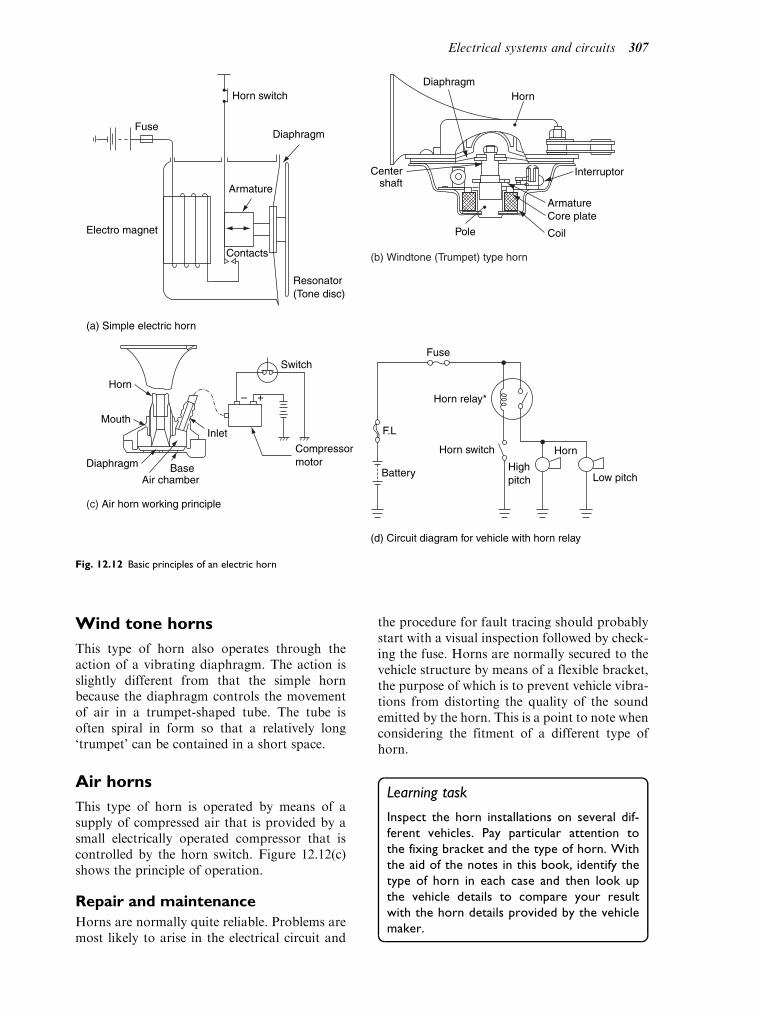
Wind tone horns
This type of horn also operates through theaction of a vibrating diaphragm. The action isslightly different from that the simple hornbecause the diaphragm controls the movementof air in a trumpet-shaped tube. The tube isoften spiral in form so that a relatively long‘trumpet’ can be contained in a short space.
Air horns
This type of horn is operated by means of asupply of compressed air that is provided by asmall electrically operated compressor that iscontrolled by the horn switch. Figure 12.12(c)shows the principle of operation.
Repair and maintenance
Horns are normally quite reliable. Problems aremost likely to arise in the electrical circuit and
the procedure for fault tracing should probablystart with a visual inspection followed by check-ing the fuse. Horns are normally secured to thevehicle structure by means of a flexible bracket,the purpose of which is to prevent vehicle vibra-tions from distorting the quality of the soundemitted by the horn. This is a point to note whenconsidering the fitment of a different type ofhorn.
Learning task
Inspect the horn installations on several dif-
ferent vehicles. Pay particular attention to
the fixing bracket and the type of horn. With
the aid of the notes in this book, identify the
type of horn in each case and then look up
the vehicle details to compare your result
with the horn details provided by the vehicle
maker.
(a) Simple electric horn
Resonator(Tone disc)
Electro magnet
Fuse
Horn switch
Diaphragm
Armature
Contacts
DiaphragmHorn
Interruptor
ArmatureCore plate
CoilPole
Centershaft
(b) Windtone (Trumpet) type horn
Horn
Mouth
Diaphragm BaseAir chamber
Inlet
Compressormotor
Switch
– +
(c) Air horn working principle
Horn relay*
Fuse
Horn switch
Battery Highpitch
F.L
Horn
Low pitch
(d) Circuit diagram for vehicle with horn relay
Fig. 12.12 Basic principles of an electric horn
Electrical systems and circuits 307

12.7 Electrically operatedwindows
Electrically operated windows are commonlyused in many types of vehicle. The two sys-tems, illustrated in Fig. 12.13, make use ofreversible electric motors. The mechanism thatis used to raise and lower the windows isknown as the regulator. In Fig. 12.13(a), theregulator is operated by a small gear on the
motor shaft that engages with a quadrant gearon the arm of the regulator. Rotation ofthe motor armature causes a semi-rotaryaction of the quadrant. This semi-rotaryaction is converted into linear motion by theregulator mechanism. The system shown inFig. 12.13(b) makes use of cables that arewound on a drum that is driven bythe operating motor. In both cases, the electricmotors are of the permanent magnet type. Thepermanent magnet motor is reversible via the
1 Window glass2 Glass stop damper3 Mounting screw (4 off)4 Forward runner5 Friction pad6 Glass clamp screw7 Motor assembly8 Cable9 Rear runner
1
9 8
2
3
4
5
6
7
M76 4004
LH regulator shown. RH similar
(b)
Fig. 12.13 Electrically operated windows. (Reproduced with the kind permission of Ford Motor Company Limited.)
Power windowregulator
Door controlrelay
Master switch
Sub-switch
Courtesyswitch
Junctionblock
(a)
308 A practical approach to motor vehicle engineering and maintenance

switching system and this permits the windowsto be operated as required. An electricallyoperated window circuit normally contains athermally operated switch to protect the circuitin the event of severe icing or other conditionthat may lead to an excessive load on themotors and winding mechanism.
12.8 Lighting
Themain purpose of lights on a vehicle is to enablethe driver to see and for other road users to be ableto see the vehicle, after dark and in other condi-tions of poor visibility. In the UK there are legalrequirements for the lights that must be fitted. Insummary, these requirements are:
1. Headlamps (minimum of two, one each side)2. Side, rear and number plate lamps3. Direction indicator lamps (flashers)4. Stop lamps (brake lights)5. Rear fog lamp (at least one).
All of these lamps must be maintained in workingcondition, including proper alignment.
Lighting regulations
The law relating to vehicle lights is quitecomplicated and you are advised to checkthe regulations to ensure that you understandthem. This is particularly important whenfitting extra lights to a vehicle.
Lighting circuit components
Bulbs
The main source of light for the lamps listedabove is the traditional bulb. Electric currentin the bulb (lamp) filament causes the filamentto heat up and give out whitish light. Whereother colours are required, for example, for stopand tail lights, the lamp lens is made fromcoloured material. Figure 12.14 shows somecommonly used types of bulbs.
Ordinary twin filament headlamp bulb
The filaments are made from tungsten wire andthe glass bulb is often filled with an inert gassuch as argon. This permits the filament to
Powerwindowmotor
(Front LH)
Power window main switch (Front LH)
Powerwindow
main relay
: Power window switch (Front RH)
: Power window switch (Rear RH)
: Power window switch (Rear LH)
Battery
Door lockcontrol relay
Door lockmotor
IG switch
Powerwindowmotor
(Front RH)
Powerwindowmotor
(Rear RH)
M M
M 1
1
2
2
M
Powerwindowmotor
(Rear LH)
3
3
M
M
M
M
M
(c)
Fig. 12.13 (Continued)
Electrical systems and circuits 309

operate at a higher temperature and increasesthe reliability. One of the filaments provides themain beam and the other filament, which isplaced a little above centre, provides the dippedbeam. The effect is shown in Fig. 12.15.
In order to locate the bulb accurately inthe lamp reflector, the metal base of thebulb is equipped with a notch, as shown inFig. 12.16.
Quartz halogen twin filament headlamp bulb
A problem with ordinary tungsten lamp bulbsis that, over a long period of time, the fila-ment deteriorates (evaporates) and discoloursthe glass. The rather more elaborate quartzhalogen bulb is designed to give brighter lightand to prevent the evaporated tungsten frombeing deposited on the inside of the bulb.Halogens are gases, such as iodine, chlorine,etc., which react chemically inside the bulbto provide the ‘halogen cycle’. The ‘halogencycle’ preserves the life of the tungstenfilament.
Oil, grease and salt from perspiration candamage the quartz and it is recommendedthat these bulbs are handled by the metal partto prevent damage. Figure 12.17 shows atypical method of locating a quartz halogentype bulb.
Stop and tail lamps
The stop/tail bulb has two filaments. Theyare normally 21 Watt and 5 Watt filaments.The 21 Watt filament is for the stop (brake)lights and the 5 Watt filament is for the taillights. The metal base of the bulb is providedwith off-set pins so that it cannot be fittedincorrectly.
Sealed beam units
The construction of a sealed beam unit is shownin Fig. 12.18.
Fig. 12.14 Typical vehicle light bulbs, (a) ordinary bulb,
(b) Quartz halogen blub
Fig. 12.15 The dipped beam principle
Fig. 12.16 The location notch in the bulb base – regular type
310 A practical approach to motor vehicle engineering and maintenance

There is no separate bulb. The assembly –lighting filaments, reflector and lamp lens isa single unit. During manufacture, the insideof the unit is evacuated and filled with inertgas and the unit is then hermetically sealed.The idea is that the dust and other contaminantscannot enter and the accuracy of the setting ofthe filament in relation to the focal point of thereflector cannot be altered. A disadvantage isthat, in the event of filament failure, the wholeunit must be replaced.
Headlamp dipping
The reflector concentrates the light produced bythe bulb and projects it in the required direction.The lens is specially patterned to ‘shape’ thelight beam so that the beam is brighter in thecentre and less bright on both sides. The inten-tion is to reduce the risk of ‘dazzling’ oncomingdrivers and pedestrians. Headlamps must also
be provided with the means to deflect the beamdownwards and, in a two headlamp system, thisis achieved by switching the lamps from themain beam filament to the dip beam filament.
Headlamp alignment
To ensure that headlamps are correctly adjusted,it is necessary to check the alignment. Specialmachines of the type shown in Fig. 12.19, areoften used for this purpose.
If such a machine is not available it is accep-table to use a flat, vertical surface such as a wallor a door.
The wall should be marked out, as shown inFig. 12.20.
The vehicle is placed so that the headlamps areparallel to the wall and 8 metres from the wall.The centre line of the vehicle must line up with
Fig. 12.17 Locating a quartz halogen bulb
Fig. 12.18 A sealed beam headlamp unit
Fig. 12.19 Lucas headlamp alignment machine
Electrical systems and circuits 311

the centre line marked on the wall and, with theheadlamps switched on to main beam, the areaof concentrated light should be very close to thatshown in Fig. 12.20. Should the settings beincorrect, it will be necessary to inspect for thecause of the inaccuracy. It may be a case ofincorrect adjustment. If adjustment is required,it is probable that the headlamp unit will beequipped with screws to alter the horizontal andvertical settings, as shown in Fig. 12.21.
Gas discharge lamps
Xenon lamps operate on the gas discharge prin-cipal. The light source (bulb) contains a pair ofelectrodes that are encased in a special type ofquartz glass bulb. The bulb is filled with Xenongas, traces of mercury and other elements, underpressure. When a high voltage of approximately20 kVolts is applied to the electrodes, the Xenongas emits a bright white light and evaporates themercury and other elements. Once illuminated,the light output of the bulb is maintained by alower voltage. Gas discharge (Xenon) lampsproduce a greater amount of light than conven-tional bulbs and are designed to last longer. Themain features of a Xenon headlamp are shownin Fig. 12.22.
Safety
The electronic control unit for the Xenon lampproduces a very high voltage and the followingprecautions must be observed:
. Ensure that the lights are switched off beforeattempting to work on the system. This is toguard against electric shock that can arisefrom the high voltage.
. Gloves and protective eye wear must be usedwhen handling Xenon bulbs and the glasspart of the bulb must not be touched.
. Discarded Xenon bulbs must be treated ashazardous waste.
Vehicles that are equipped with Xenon lampsmust also be equipped with a means of auto-matically adjusting the lamps to prevent daz-zling of oncoming drivers.
Headlight and rear fog light circuit
In the circuit shown in Fig. 12.23, the rear foglamp circuit is fed from the main light switch.The purpose of the rear fog lamp is to make thepresence of the vehicle more visible in difficultdriving conditions. The headlamps are con-nected in parallel so that failure of one lampdoes not lead to failure of the others.
Direction indicators
Direction indicator lights (flashers) arerequired so that the driver can indicate anyintended manoeuvre. Figure 12.24 shows atypical indicator lamp circuit circuit. The‘flasher’ unit is designed so that the frequencyof flashes is not less than 60 per minute and notmore than 120 per minute. The circuit is alsodesigned so that failure of an indicator lampwill lead to an increased frequency of flashingand the driver will notice this at the warninglight.
The ‘flasher’ unit
The unit shown in the above circuit is marked8FL. This is a Lucas unit that operates on thebasis of thermal expansion and contraction of ametal strip. The flasher unit shown in Fig. 12.25
Fig. 12.20 Using a marked wall for headlamp alignment
Fig. 12.21 Headlamp alignment screws
312 A practical approach to motor vehicle engineering and maintenance

employs a capacitor and a relay to provide theflashing action. Examination of the circuitdiagram shown in Fig. 12.25 shows that thecontact points are normally at rest in the closedposition. When the indicator switch is moved toindicate a turn, to left or right, current flows tothe indicator lamps, through the upper windingof the relay. This current energises the relay andopens the contact points, the current flow isinterrupted and the lamps ‘go out’. As the lampsgo out, the contact points close and the lights‘come on’ again. This happens at a frequency ofapproximately 90 flashes per minute and thetiming of the flash rate is controlled by thecapacitor.
12.9 Circuits and circuitprinciples
Circuit (wiring) diagrams
A complete circuit is needed for the flow of elec-tric current. Figure 12.26 shows two diagrams ofa motor in a circuit. Should the fuse be blown, thecircuit is incomplete, current will not flow and themotor will not run. In the right-hand diagram,the fuse has been replaced. The circuit is nowcomplete and the motor will run. Basic electricalprinciples such as this, are fundamental to goodwork on electronic systems because much of the
BatteryLight control
computer
Xenon gas
LightLight
Light
Metal halidebulb
Mercuryevaporation
Electronic unit
Reflector
Xenon bulb
Bulb retention cap
Fig. 12.22 The gas discharge (Xenon) lamp. (Reproduced with the kind permission of Ford Motor Company Limited.)
Electrical systems and circuits 313

testing of electronic systems requires checking ofcircuits to ensure that they are complete.
It is essential to be able to understand andfollow circuit diagrams and this requires aknowledge of circuit symbols. There is a set of
standard circuit symbols, some of which areshown in Fig. 12.27.
However, non-standard symbols of the typeshown in Fig. 12.28, are sometimes used andthis can cause confusion. Fortunately, when
Fig. 12.23 Headlamp and rear fog lamp circuit
Fig. 12.24 Indicator lamp circuit
314 A practical approach to motor vehicle engineering and maintenance

non-standard symbols are used, they are nor-mally accompanied by a descriptive list.
Figure 12.29 gives an example of the use of adescriptive list to support the wiring diagram;the injector resistors are shown as a sawtoothline, number 21 on the list, and on the diagram.
This solves the problem of decyphering thediagram.
Colour code
The wiring diagram is an essential aid to faulttracing. The colour code for wires is an import-ant aid to fault tracing and most wiringdiagrams make use of it.
A commonly used colour code:
N ¼ brown Y ¼ yellowP ¼ purple K ¼ pinkW¼white R ¼ redO ¼ orange LG¼ light greenU ¼ blue B ¼ blackG ¼ green S ¼ slate
In order to assist in tracing cables, they are oftenprovided with a second colour tracer stripe. Thewiring diagram shows this by means of letters,for example, a cable on the wiring diagram, withGB written on it, is a green cable with a blacktracer stripe. The first letter is the predominantcolour and the second is the tracer stripe.
Note: This is not a universal colour code and,as with many other factors, it is always wise tohave accurate information to hand, that relatesto the product being worked on.
The predominant (main) colours frequentlyrelate to particular circuits as follows:
Brown (N)¼Main battery feedsWhite (W)¼Essential ignition circuits (not fused)Light green and also Green (LG) (G)¼Auxiliary ignition circuits (fused).Blue (U)¼Headlamp circuits.Red (R)¼ Side and tail lamp circuits.Black (B)¼Earth connections.Purple (P)¼Auxiliary, non-ignition circuits,
probably fused.
Fig. 12.25 Capacitor and relay flasher unit and circuit (a)
construction of the flasher units, (b) circuits for the two types
of flasher unit
Fig. 12.26 An electric circuit
Electrical systems and circuits 315

Fig. 12.27 A selection of circuit symbols
Fig. 12.28 Non-standard circuit symbols
316 A practical approach to motor vehicle engineering and maintenance

Fig. 12.29 System diagram with list describing circuit elements
Electrical systems and circuits 317

A complete wiring diagram
Figure 12.30 shows a full wiring diagram for avehicle. In order to make it more intelligible, thisdiagram uses a grid system. Numbers 1 to 4 acrossthe page, and letters A, B, C, at the sides. Thismeans that an area of diagram can be located. Forexample, the vehicle battery is in the grid area 1A.
The wiring loom, or harness
It is common practice to bind cables together tofacilitate positioning them in the vehicle struc-ture. It used to be the practice to fabricate theloom, or harness, from a woven fabric. Modernloom sheathing materials are usually a PVCtype of material. Figure 12.31 shows the enginecompartment part of a typical wiring loom.
Cable sizes
The resistance of a cable (wire) is affected by,among other factors, its diameter and its length.For a given material, the resistance increases withlength and decreases with diameter. Doubling agiven length of cable will double its resistance anddoubling the diameter of the same length of cablewill decrease the resistance to 1/4th of the originalvalue. Cable sizes are, therefore, important, andonly those sizes specified for a given applicationshould be used. Most cables used on vehicles needto be quite flexible. This flexibility is provided bymaking the cable from a number of strands of wireand it is common practice to specify cable sizesby the number of strands and the diameter of eachstrand, for example, 14/0.30 means 14 strandsof wire and each strand has a diameter of 0.30mm.
Some typical current carrying capacities ofcables for vehicle use are:
The choice of cable is a factor that is decidedat the design stage of a vehicle. However, itsometimes affects vehicle repair work when,for example, an extra accessory is being fittedto a vehicle, or a new cable is being fitted toreplace a damaged one. In such cases, themanufacturers’ instructions must be observed.
Circuit protection
Fuses
The purpose of the fuse is to provide a ‘weak’link in the circuit which will fail (blow) if thecurrent exceeds a certain value and, in so doing,protect the circuit elements and the vehicle fromthe damage that could result from excess current.
The fuse is probably the best known circuitprotection device. There are several differenttypes of fuses and some of these are shown inFig. 12.32. Fuses have different current ratingsand this accounts for the range of types avail-able. Care must be taken to select a correctreplacement and larger rated fuses must neverbe used in an attempt to ‘get round’ a problem.Many modern vehicles are equipped with a‘fusible link’ which is fitted in the main batterylead as an added safety precaution.
It is commonpractice to place fuses together in areasonably accessible place on the vehicle. Anotherfeature of the increased use of electrical/electroniccircuits on vehicles is an increase in the number offuses to be found on a vehicle. Figure 12.33 showsan engine compartment fuse box that carries fusi-ble links in addition to ‘normal’ fuses.
The same vehicle also has a dashboard fuse-box. This also carries ‘spare’ fuses which appearto the right of the other fuses (Fig. 12.34).
Whilst, in the event of circuit failure, it iscommon practice to check fuses and replaceany ‘blown’ ones, it should be remembered thatsomething caused the fuse to blow. Recurrentfuse ‘blowing’ requires that circuits should bechecked to ascertain the cause of the excesscurrent that is causing the failure.
The circuit breaker
The thermal circuit breaker relies for its operationon the principle of the ‘bi-metallic strip’. InFig. 12.35, the bi-metal strip carries the currentbetween the terminals of the circuit breaker. Excesscurrent, above that for which the circuit isdesigned,will cause the temperature of the bi-metalstrip to rise to a level where it will curve and causethe contacts to separate. This will open the circuitand current will cease to flow. When the tempera-ture of the bi-metal strip falls the circuit will bere-made.This action leads to intermittent function-ing of the circuit which will continue until the faultis rectified. An application may be of a 7.5 amperecircuit breaker to protect a door lock circuit. Theadvantage of the circuit breaker, over a fuse, is thatthe circuit breaker can be re-used.
Size of cable Current rating Typical use
14/0.30 8.75 amps Side and tail lamps
28/0.30 17.5 amps Headlamps
120/0.30 60 amps Alternator to battery
318 A practical approach to motor vehicle engineering and maintenance

Fig
.12.3
0A
typic
alw
irin
gdia
gram

Other circuit protection
Vehicle circuits are subject to ‘transient’ voltageswhich arise from several sources. Those whichinterest us here are load dump, alternator fielddecay voltage, switching of an inductive device
(coil, relay, etc.) and over voltage arising fromincorrect use of batteries when ‘jump starting’.
Load dump occurs when an alternatorbecomes disconnected from the vehicle batterywhile the alternator is charging, i.e., when theengine is running.
Figure 12.36 shows a Zener diode, as usedfor surge protection in an alternator circuit.The breakdown (Zener) voltage of the diode is10 to 15 volts above the normal system voltage.Such voltages can occur if an open circuit occursin the main alternator output lead when theengine is running. Other vehicle circuits, suchas coil ignition, can also create inductive surges.Should such voltage surges occur, they coulddamage the alternator circuits but, with theZener diode connected as shown, the excessvoltage is ‘dumped’ to earth via the Zener diode.
Fig. 12.31 Engine compartment wiring loom
Fig. 12.32 Fuse types
320 A practical approach to motor vehicle engineering and maintenance

Should such a voltage surge occur, it maydestroy the protection diode. The alternatorwould then cease charging. In such a case, thesurge protection diode would need to bereplaced, after the cause of the surge had beenremedied.
Figure 12.37 shows another form of circuitprotection where a diode is built into a cableconnector. This reduces the risk of damagefrom reversed connections and it is evidentthat one should be aware of such uses
because a continuity test on such a connectorwill require correct polarity at the meterleads.
Connectors
Connectors are used to connect cables to compo-nents and to join cables together. They are madein a range of different shapes and sizes for avariety of purposes, as shown in Fig. 12.38. InFig. 12.38(b), a pair of cables are joined together
Fig. 12.33 Engine compartment fusebox (Rover 800)
Electrical systems and circuits 321

by a connector and in Fig. 12.38(c), some cablesare connected to a component. Figure 12.38(a)shows the principal parts of a connector. Theseparts are designed to be resistant to vibrationand moisture. In some cases, such as the multiplepin connector for an ECU that is shown inFig. 12.38(d), the pins are coated with gold to
ensure the type of electrical connection that isneeded for very small electric current.
Repair and maintenance
Some service and repair operations may requirecomponents and cables to be disconnected. Insuch cases, the procedures for taking connectors
Fig. 12.34 Dashboard fusebox (Rover 800)
322 A practical approach to motor vehicle engineering and maintenance

apart should be observed and care taken toavoid damage to the pins. Damage to pins maycause the connection to develop a high resis-tance or to fail completely. Should it be neces-sary to probe connections, in an endeavour totrace a fault, every effort should be made toprevent damage to waterproofing and electricalinsulation.
12.10 Instrumentation
Vehicles are equipped with instruments and otherwarning devices, in order to inform the driverabout the current state of various systems on
the vehicle. Some instruments, such as the speed-ometer, the fuel tank contents gauge, the oil pres-sure gauge and the ignition warning, have beenfeatures of the instrument display on vehicles formany years. Several of the more commonly usedinstruments are examined below, in order toassess the technology involved and to examinesome approaches to fault tracing.
Thermal type gauges
These instruments make use of a bi-metal strip toprovide the movement that gives an indication ofthe quantity that is being measured. In the exam-ple of the fuel tank contents gauge, that is shownin Fig. 12.39, the current flowing in the metercircuit is dependent on the resistance of the sen-sing unit at the fuel tank. As the float of the fueltank sensing unit rises and falls with fuel level, sothe resistance that it places in the meter circuitchanges. Changes in resistance cause the currentflowing in the heating coil that surrounds the bi-metal strip to change and this leads to changes inthe temperature of the bi-metal strip. Thus, theheating effect of the current that deflects the bi-metal strip varies with fuel level and, by carefulcalibration, the fuel gauge is made to give a reli-able guide to the quantity of fuel in the tank.
The engine coolant temperature gauge, that isalso shown in Fig. 12.39, operates on the same
Fig. 12.35 A circuit breaker (Toyota)
Fig. 12.36 Voltage surge protection by Zener diode
Electrical systems and circuits 323

principle as the fuel contents gauge, except thatthe variable resistance is provided by the ther-mistor. A thermistor has a negative temperaturecoefficient which means that the resistance ofthe thermistor decreases as its temperature rises.It is this variation of resistance that cause themeter current to change and thus indicate thecoolant temperature.
The voltage stabiliser
Reliable operation of thermal type meters isdependent on a reasonably constant voltagesupply and the voltage stabiliser is the meansof providing a stable voltage. In the type ofvoltage stabiliser shown in Fig. 12.39, thecurrent in the meter circuit causes the tempera-ture of the voltage stabiliser bi-metal strip toFig. 12.37 A protection diode in a cable connector
(a) Basic parts of a cable connector
MaleFemale
Lock
ER/33/38
(b) (c)
ER/33/45
(d)
1 2 3 4 5 6 7 8 9 10 11 12 13 14 15 16 17 18 19 20 21 22326273
OR/33C/13
Fig. 12.38 Types of cable connectors. (Reproduced with the kind permission of Ford Motor Company Limited.)
324 A practical approach to motor vehicle engineering and maintenance

heat up and bend. The heating and bendingaction causes the voltage stabiliser contact toopen, thus stopping the current flow. Thetemperature of the bi-metal strip then dropsand the contacts close. This process proceeds athigh frequency and provides a reasonably con-stant voltage level at the meter. An alternativemethod of voltage stabilisation is shown inFig. 12.39(c). This type of stabiliser makes useof the breakdown voltage of an avalanche(Zener) diode. When the voltage at the terminalsexceeds the breakdown value, the diode conductsand effectively ‘absorbs’ the excess voltage.
A vacuum fluorescent display gauge
The vacuum fluorescent display makes use of anumber of segments. Each segment of the displayis activated electronically through a circuit simi-lar to that shown in Fig. 12.40(a). Figure12.40(b) shows the main features of a single
element of a VFD. The fluorescent material, thegrid and the filament are encased in a vacuumcompartment. When a segment is activated bythe electronic circuit, a stream of electronsbombards the fluorescent material which causesit to emit light. The filament is negatively chargedand heated to approximately 600 C. At this tem-perature electrons are released to pass throughthe grid towards the positively charged segment,where they cause the display to emit light.
Liquid crystal displays (LCDs) and lightemitting diode displays (LEDs) are also usedin many similar applications. They are alsodriven by electronic circuits similar to thatshown in Fig. 12.40(a).
Vehicle condition monitoring (VCM)
Gauges, such as the oil pressure gauge, theammeter, and warning lights (i.e., those thatlight up when the brake pads are worn), are all
Fuel sender gauge(sliding resistor)
Voltageregulator
Fuel receivergauge
Water temperaturesender gauge(Thermistor)Water temperature
receiver gauge
Heatwire
Ignitionswitch
E F
H C
(a) Thermal type gauge circuits
V Regulated voltagesupply to instrument
(c) Zender diode type voltage regulator
Float
Float arm
Slidingresistor
Terminal
(b) Variable resistor fuel tank sender unit
Fig. 12.39 A thermal type fuel gauge and variable resistor sender unit. (Reproduced with the kind permission of Ford Motor Company
Limited.)
Electrical systems and circuits 325

examples of instruments that continuouslymonitor the condition of various parts of thevehicle. The extensive use of computer con-trolled systems on vehicles means that manyof the factors that affect the use of a vehicleare constantly monitored because it is themonitoring that provides the data that allowsthe systems to operate. Vehicle conditionmonitoring has thus evolved so that it hasbecome a feature on all modern vehicles. Themost striking example is probably that providedby on board diagnostics. Modern computer
controlled systems have sufficient memoryand processing capacity to constantly check alarge number of variables and to take actionif any variable (measurement) is wrong. Thisaction may be to store a fault code in thememory, or it may be to illuminate a warninglamp to alert the driver. The European (EOBD)version of condition monitoring requires theuse of a malfunction indicator lamp MIL.The MIL is illuminated when any item of equip-ment that affects vehicle emissions develops afault.
(c) Instrument panel displays
VFDLCD LED
High
Low
Speed Fuel
Full
¼
½
¾
RPM
(b) Vacuum fluorescent display VFD
Grid Filament
Electrons
Brightnesscontrol
Electronicswitch
Anodesegments
Glass
(a) A vacuum fluorescent gauge circuit
DisplayIC
DisplayIC
Fuel sendergauge
Centralprocessor
Enlargementswitch
5 V
A /DCon-verter
VFD
E
FComputer
Fig. 12.40 Types of instrument displays. (Fig. 12.40(a) – Reproduced with the kind permission of Ford Motor Company Limited.)
326 A practical approach to motor vehicle engineering and maintenance

12.11 Supplementaryrestraint systems (SRS)
Air bags of the type shown in Fig. 12.41, andseat belt pre-tensioners, such as that shown inFig. 12.42, are features of a basic supplemen-tary restraint system. In the event of a frontalimpact of some severity, the air bags and seatbelt pre-tensioners are deployed. The air bagsare inflated to protect those provided withthem from impact with parts of the vehicle.The seat belt pre-tensioners are made to oper-ate just before the air bags are inflated and theyoperate by pulling about 70mm of seat belt onto the inertia reel of the belt. This serves to pullthe seat occupant back on to the seat.
The deployment of these supplementaryrestraint devices is initiated by the action of thecollision detection sensing system. A collisiondetection sensing system normally utilises signals
from two sensors. One sensor is a ‘crash sensor’and the other is a ‘safing sensor’. The safing sensoris activated at a lower deceleration than the crashsensor (about 1.5 g less) and both sensors musthave been activated in order to trigger the supple-mentary restraint system.The safing sensor is fittedto reduce the risk of a simple error bringing the airbag into operation. Both of these sensor may befitted inside the electronic control unit which, insome cases, is known as a diagnostic and controlunit (DCU) because it contains the essential selfdiagnosis circuits in addition to the circuits thatoperate the SRS. Figure 12.43 shows the layout ofa supplementary restraint system on aRoverMini.
Air bags and seat beltpre-tensioners
Air bags are made from a durable lightweightmaterial, such as nylon, and in Europe they havea capacity of approximately 40 litres. The pyro-technic device that provides the inert gas to inflatethe air bag contains a combustion chamber filledwith fuel pellets, an electronic igniter and a filter,as shown in Fig. 12.44. Combustion of the fuelpellets produces the supply of nitrogen thatinflates the air bag. The plastic cover that retainsthe folded air bag in place at the centre of thesteering wheel is designed with built in break lines.When the air bag is inflated, the plastic coverseparates at the break lines and the two flaps openout to permit unhindered inflation of the air bag.
The seat belt pre-tensioners are activated by asimilar pyrotechnic device. In this case the gas isreleased into the cylinder of the pre-tensioner,where it drives a piston along the cylinder. TheFig. 12.41 Airbags for driver and front seat passenger
Electricalconnection
Tube and piston
Connecting cable
Inertia reel
Seat belt
Fig. 12.42 Operation of pre-tensioner
Electrical systems and circuits 327

piston is attached to a strong flexible cable thatthen rotates the inertia reel of the seat belt by asufficient amount to ‘reel in’ the seat belt byapproximately 70mm.
The rotary coupler
This device is fitted beneath the steering wheelto provide a reliable electrical connectionbetween the rotating steering wheel and airbag, and the static parts of the steering column.The positioning of the rotary coupler is a criticalelement of the air bag system and it should notbe tampered with. When working on supple-mentary restraint systems, it is important thata technician is fully acquainted with the systemand procedures for working on it.
Handling SRS components
The following notes are provided to Rovertrained technicians and they are included here
because they contain some valuable advice forall vehicle technicians.
Safety precautions, storage andhandling
Airbags and seat belt pre-tensioners are capableof causing serious injury if abused or mis-handled. The following precautions must beadhered to:
In vehicle. ALWAYS fit genuine new parts when repla-
cing SRS components;. ALWAYS refer to the relevant workshop
manual before commencing work on a sup-plementary restraint system;
. Remove the ignition key and disconnectboth battery leads, earth lead first, and wait10 minutes to allow the DCU back-up powercircuits to discharge before commencingwork on the SRS;
1. Driver’s airbag module2. Seatbelt pre-tensioner3. SRS warning light
4. Diagnostic and control unit5. Rotary coupler6. SRS wiring harness
3
2
6
1
5
4
Fig. 12.43 The elements of a supplementary restraint system (Rover Mini)
328 A practical approach to motor vehicle engineering and maintenance

. DO NOT probe SRS components or harnesswith multi-meter probes, unless followinga manufacturer’s approved diagnostic routine;
. ALWAYS use the manufacturers approvedequipment when diagnosing SRS faults;
. Avoid working directly in line with the airbag when connecting or disconnecting multi-plug wiring connectors;
. NEVER fit an SRS component which showssigns of damage or you suspect has been abused.
Handling. ALWAYS carry airbag modules with the
cover facing upwards;. DO NOT carry more than one airbag module
at a time;. DO NOT drop SRS components;. DO NOT carry airbag modules or seat belt
pre-tensioners by their wires;. DO NOT tamper with, dismantle, attempt to
repair or cut any components used in thesupplementary restraint system;
. DO NOT immerse SRS components in fluid;
. DO NOT attach anything to the airbagmodule cover;
. DO NOT transport and airbag module orseatbelt pre-tensioner in the passenger com-partment of a vehicle. ALWAYS use theluggage compartment.
Storage. ALWAYS keep SRS components dry;. ALWAYS store a removed airbag module
with the cover facing upwards;. DONOT allow anything to rest on the airbag
module;. ALWAYS place the airbag module or pre-
tensioner in the designated storage area;. ALWAYS store the airbag module on a flat,
secure surface well away from electricalequipment or sources of high temperature.
N.B
Airbag modules and pyrotechnic seatbeltpre-tensioners are classed as explosive arti-cles and, as such, must be stored overnightin an approved, secure steel cabinet which isregistered with the Local Authority.
Disposal of airbag modules and pyrotechnicseatbelt pre-tensioners
If a vehicle that contains airbags and seatbeltpre-tensioners that have not been deployed (acti-vated) is to be scrapped, the airbags and seatbeltpre-tensioners must be rendered inoperable byactivating them manually prior to disposal. Thisprocedure may only be performed in accordance
with the manufacturer’s instruction manual.
Self assessment questions
1. The approximate electric current used by a
12 volt wiper motor, when it is in proper
operating condition, is:
(a) 1.5 A to 4 A
(b) 15 A to 40 A
(c) 0.15 A to 0.4 A
(d) 6 Watts
2. Remote controllers for central locking are
infrared or radio frequency devices. The
source of energy that provides the power for
the remote control device is:
(a) an electro magnet in the key
(b) a small battery in the key
(c) static electricity
(d) a thermionic valve
3. Two additives that are added to water to
make screen washer fluid are:
(a) liquid paraffin and salt
(b) anti-freeze and detergent
FilterInitiator Enhancer
Propellant grain
To the bag
Propagation of fireFlow of nitrogen gas
To the bag
Fig. 12.44 A pyrotechnic device for inflating airbags
Electrical systems and circuits 329

(c) boiling point depressant and descaler
(d) distilled water and rubber lubricant
4. Regenerative braking of a screen wiper motor
is achieved by:
(a) a clamping action on the wiper mechanism
(b) electrically connecting the two main
brushes of a permanent magnet motor
(c) a mechanical brake on the wiper motor
driving gears
(d) the back emf from the wiper control
switch
5. By what means is the self parking action of
wiper blades achieved:
(a) a cam operated trip switch at the motor
switches the motor off when the park
position is reached
(b) a mechanism that permit’s the driver to
stop the wiper arms at any point on the
screen
(c) a rheostat that is built into the switch circuit
(d) a sensor built into the screen
6. A wind tone horn circuit contains a relay:
(a) to reduce power loss
(b) because of the high current
(c) to vibrate the diaphragm
(d) to reduce arcing at the horn switch
7. Instrument circuits require a steady voltage
that is provided by:
(a) a relay
(b) a voltage stabiliser
(c) a field effect transistor
(d) a separate battery
8. Electrically operated windows are operated by:
(a) linear motors
(b) semi-rotary induction motors
(c) reversible permanent magnet motors
(d) powerful solenoids
9. Headlamps are connected:
(a) in series
(b) in parallel
(c) by a Wheatstone bridge
(d) by a failure mode analysis circuit
10. Hazard warning lights:
(a) make use of the direction indicator lamps
circuit
(b) operate in conjunction with the fuel circuit
inertia switch
(c) operate by causing the stop lamps to flash
(d) use 5 Watt MES bulbs
11. List 3 factors that may cause scratching of the
windscreen
12. Make a list of the possible causes of a weak
spray of washer fluid from the jets on to the
screen
13. Describe a simple procedure to test a theft
alarm system
Learning tasks
1. Identify the headlamp alignment equip-
ment that is used in your workplace.
Study the instructions for use and consult
with you training supervisor to arrange
sessions when you will learn how to use
the equipment.
2. Examine a number of vehicles and note the
procedures that must be followed in order
to replace headlamp bulbs and bulbs in any
other external lamps on the vehicles.
3. Examine a number of screen wiper blades
and, with the aid of sketches and a few
notes, explain the procedure for replacing
worn squeegees.
4. With the aid of workshop manuals, locate
the fuse boxes on a number of vehicles.
Make a note of the different types of fuses
that you have seen and discuss with your
supervisor the procedure for replacing
blown fuses.
5. Locate the heated rear screen relay on a
vehicle and write down an explanation as
to why it is placed where it is. Explain this
to your training supervisor.
6. Examine a number of vehicles to locate
the position of the horn. Use the manual
to find the position of the horn relay and
fuse.
7. Describe the procedure for dealing with air-
bags when a repair operation entails
removal of a steering wheel.
330 A practical approach to motor vehicle engineering and maintenance

13Measuring instruments andmeasurement
Topics covered in thischapter
Micrometers
Vernier calipers
Feeler gauges
Number approximations – typical motor vehicle
measurements
Electrical test meters
Accurate measurement plays an important partin vehicle maintenance and repair. For example,measurements that are routinely taken are:
. valve clearances
. steering angles and track alignment
. exhaust emissions
. compression pressures
. alternator charging rate
. tyre pressures
. brake disc ‘run out’
. brake disc thickness, brake pad thickness
. shaft and bearing clearances.
Figure 13.1 shows a number of examples of thetypes of measurements and the measuringinstruments that are used in motor vehicle main-tenance and repair work.
OR 21–95
1 2
(a) Feeler gauges
Check valve clearances.
K
AB
C
D
ER17–70N
Measure drive train end float with measuringtool 17–025 and depth gauge (or feeler gauge) A – Needle bearing No.11 B – Oil pump gasket C – Measuring with feeler gauge D – Distance between lower edge of measuring tool and needle bearing
(b) Straight edge & vernier gauge
(c) Micrometer – crank dimensions
ER/12/32
A – Steering armB – Holding fixture
C – DiscD – Dial indicator
A
C
D
B
(d) Dial test indicator
T1 ER/12/33
Rotating the disc using a socket and wrench.
(f) Rotating a brake disc to check run-out(e) Vernier caliper – outside diameter of a bush
Fig. 13.1 Measuring instruments and their uses

13.1 Measuringinstruments
Feeler gauges
Feeler gauges are used in motor vehicle repairand maintenance for such purposes as check-ing valve clearances, piston ring gaps andmany other clearances. The feeler gauges,shown in Fig. 13.2, are typical of the typethat form a part of a technician’s tool kit.They are made from high-grade steel that istempered for hard wear and durability andthe size of each blade is etched into thesurface.
Figure 13.1(a) shows a feeler gauge in use,measuring valve clearance. In this example, thefeeler gauge is being inserted between the heelof the cam and the cam follower, with thevalve in the fully closed position. When readyto proceed with the measurement, the gaugesof the required thickness are inserted in theclearance between the heel of the cam andthe cam follower and a light-hand force, suffi-cient to slide the feeler gauge through the gap,is applied.
Non-magnetic feeler gauges
Feeler gauges made from brass or some othernon-magnetic material, such as a suitable plas-tic, are used to check the air gap on some typesof electronic ignition distributors.
Vernier calipers
Figure 13.1(b) shows the depth gauge sectionof a vernier caliper being used to check thedrive train end-float in a final drive assembly.
In this application the vernier gauge is beingused in conjunction with an engineer’sstraight edge. Figure 13.3 shows a Verniergauge in greater detail. This instrumentmeasures to an accuracy of 0.02mm, whichis quite adequate for most vehicle repair andmaintenance work. As indicated in the dia-gram, the instrument is versatile as it maybe used for internal, external and depth mea-surements. The instrument should be treatedcarefully and kept in clean dry conditionswhen not in use.
Reading a vernier scale
For the following explanation please refer to themetric reading at the bottom of Fig. 13.3.
Themain scale is graduated in millimetres andare numbered at every 10 divisions. The vernierscale is divided into 50 divisions over a distanceof 49mm and each division is equal to 49/50thsof a mm, that is 0.98mm. The differencebetween the divisions on the two scales is1.00 0.98¼ 0.02mm.
To read the measurement, note the main
scale reading up to the zero on the vernier
scale. In this example, that is a reading of21mm. To this reading must be added thedecimal reading on the vernier scale. This isobtained by noting the line on the vernier
scale that exactly lines up with a line on themain scale. In this case the scales align at 7large divisions and 3 small divisions of thevernier scale. The 7 large divisions represent0.7mm and the 3 small divisions represent3 0.02mm¼ 0.06mm.
This gives a total reading¼ 21mmþ 0.7mmþ0.06mm¼ 21.76mm
Micrometers
Figure 13.1(c) shows an external micrometerbeing used to check the diameter of a crankpin.Crankshaft measurement is normally only per-formed when an engine has operated for manythousands of miles, or when some failure hasoccurred as a result of running the engine shortof oil or a related problem. The reason forchecking the crank diameter is to assess its con-dition and thus ensure that the crank is suitablefor further use.
Micrometers are available in a range of sizes,for example, 0 inch to 1 inch (0mm to 25mm),1 inch to 2 inch (25mm to 50mm), etc.
Fig. 13.2 A set of feeler gauges. (Reproduced with the kind
permission of Bowers Metrology Group.)
332 A practical approach to motor vehicle engineering and maintenance
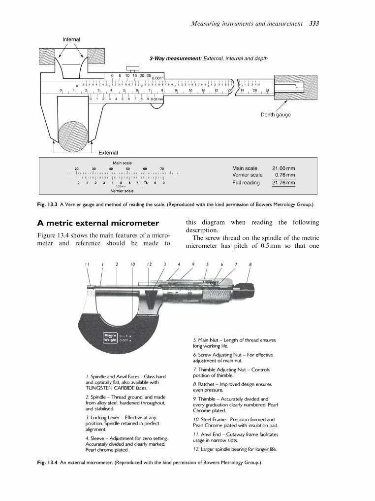
A metric external micrometer
Figure 13.4 shows the main features of a micro-meter and reference should be made to
this diagram when reading the followingdescription.
The screw thread on the spindle of the metricmicrometer has pitch of 0.5mm so that one
0 5 10 15 20 250.001"
0 1 2 3 4 5 6 7 8 9
1 2 3 4 5 6 7 8 9
00 1 2 3 4 5 6 7 8 91 1 2 3 4 5 6 7 8 92 1 2 3 4 5 6 7 8 9 93 1 2 3 4 5 6 74 1 2 3 4 57
1 2 3 4 5 6 7 8 9
0.02 mm
10 11 12 13 19 2 0 21
Main scale
Vernier scale
Main scaleVernier scale
Full reading
21.00 mm0.76 mm
21.76 mm
Internal
Depth gauge
3-Way measurement: External, internal and depth
20 30 40 50 60 70
0 01 2 3 4 5 6 7 8 90.02 mm
External
Fig. 13.3 A Vernier gauge and method of reading the scale. (Reproduced with the kind permission of Bowers Metrology Group.)
Fig. 13.4 An external micrometer. (Reproduced with the kind permission of Bowers Metrology Group.)
Measuring instruments and measurement 333

complete turn of the thimble willmove the spindleby 0.5mm. The thimble is marked in 50 equaldivisions, each of which is equal to 0.01mm.
The sleeve is graduated in two sets of lines,one set on each side of the datum line. The set ofdivisions below the datum line read in 1mm andthe set above the datum line are in 0.5mm divi-sions. (NOTE – on some micrometers, thesepositions are reversed).
Reading a micrometer
When taking measurements, the force exertedon the thimble must not be excessive andto assist in achieving this, most micrometersare equipped with a ratchet which ensures thata constant force is applied when measurementsare being taken. For measuring small diameters,the micrometer should be held approximately,as shown in Fig. 13.5. Larger micrometersrequire the use of both hands.
Taking the reading
Please refer to Fig. 13.6.The procedure is as follows:
. First note the whole number of millimetredivisions on the sleeve. These are calledMAJOR divisions.
. Next observe whether there is a 0.5mm divi-sion visible. These are called minor divisions.
. Finally read the thimble for 0.01mm divi-sions. These are called thimble divisions.
. Taking the metric example shown in Fig. 13.6,the reading is:
MAJOR divisions¼ 10 1.00¼ 10mmMINOR divisions¼ 1 0.50¼ 0.50mmTHIMBLE divisions¼ 16 0.01¼ 0.16mm
. These are then added together to give a read-ing¼ 10.66mm.
Learning activity
Figure 13.8 shows a rage of micrometer
scales. Write down the dimensions repre-
sented by these scale readings and compare
your answers with those given at the end of
this chapter.
Micrometers for larger diameters
A wide range of diameters may be encounteredin vehicle repair work and an adjustable micro-meter is useful for covering several ranges ofdiameters. The micrometer shown in Fig.13.7(a) has a number of interchangeable anvilsthat may be screwed into place to suit the dia-meter being measured.
Figure 13.7(b) shows the range of diameters,from a large piston to a small shaft, that canbe measured with an instrument of this type.Larger micrometers of the type shown hereshould be held in one hand while the thimble isturned with the other.
Internal micrometer
Internal micrometers are used to measuredimensions, such as cylinder bore diameter,internal diameter of a hole into which a bearingis to be inserted and other machinedholes where the dimensions of the internaldiameter are critical. Figure 13.9(a) shows aninternal micrometer being used for suchmeasurement.
Internal micrometers consist of a measur-ing head and extension pieces suitable for arange of measurements and the handle per-mits measurements to be taken in deep holessuch as the cylinder of an engine. The prin-cipal features of an internal micrometerare shown in Fig. 13.9(b). The micrometer
Method of holding the micrometer
Fig. 13.5 Using the micrometer on a small diameter.
(Reproduced with the kind permission of Bowers Metrology
Group.)
Datumline
Sleeve
Thimble
1010
20
15
25
50
Minor
Major
Fig. 13.6 The micrometer scales
334 A practical approach to motor vehicle engineering and maintenance

Typical applications
(b)
Anvillocknut
Anviladjusting
nuts
Anvil
Frame Anvil peg
Sectionalview
Standards Keys
Interchangeable anvils
50%
25%
75%
(a)
0-100%
Fig. 13.7 An adjustable micrometer and its uses. (Reproduced with the kind permission of Bowers Metrology Group.)
Datumline
Sleeve
55
1010
15
Thimble
(a)
Datumline
Sleeve
1510
2015
20
Thimble
(b)
Micrometer size 0–25 mm
Micrometer size 25–50 mm
Datumline
Sleeve
100
155
10
Thimble
(c)
Datumline
Sleeve
0
25
530
35
Thimble
(d)
Micrometer size 75–100 mm
Micrometer size 0–25 mm
Fig. 13.8 Exercises on reading micrometer scales
Measuring instruments and measurement 335

scale is read in a similar way to that shownin the external micrometer section of thischapter.
Mercer cylinder gauge
Because piston rings do not reach the top edgeof the cylinder bore, when the piston is at thetop of its stroke, an unworn ridge developsat the top of the cylinder and further cylinderbore wear occurs on the side where most thrustis exerted. This means that the cylinders of anengine wear unevenly from top to bottom ofthe stroke. In order to assess cylinder borewear, it is necessary to measure the diameterat several points and the Mercer gauge hasbeen developed for this purpose. Figure 13.10shows a Mercer gauge. The gauge can bezeroed by setting it to the diameter of theunworn section at the top of the cylinder bore,or more accurately, by means of an outsidemicrometer.
Once zeroed, the bar gauge is inserted into thecylinder, as shown in Fig. 13.10. Measurementsare taken in line with, and at right angles to, thecrankshaft. The maximum difference betweenthe standard size and gauge reading is the wear.The difference between the in-line reading andthe one at right angles is the ovality. The mea-surements are repeated at points in the cylinder,as shown in Fig. 13.11 and differences betweenthe diameter at the top and bottom of the cylin-der are referred to as taper.
The measurements taken may then be com-pared with the quoted bore size and excessivewear can be remedied by reboring or, in the caseof minor wear, new piston rings.
Calipers, inside and out
Figure 13.11 show internal and external calipersbeing set against a steel rule prior to makingmeasurements of inside and outside diameters.These types of measurements may be found
Extension rods
Handle
Spacingcollar
Internalmicrometermeasuring
precisionbore
190:210
170:190
150:170
130:150
90:110 70:90
10 mm
110:130
1510
0
4540
Fig. 13.9 An internal micrometer. (Reproduced with the kind permission of Bowers Metrology Group.)
336 A practical approach to motor vehicle engineering and maintenance

useful in assembly work, such as fitting newparts where it may be necessary to check onediameter against another.
Dial test indicators
Dial test indicators of the type shown in Fig. 13.12are used for measurements, such as checkingrun-out on brake discs and checking end floaton a crankshaft.
There are many other instances where a DTIwould be used, but the following two exampleswill suffice to explain the principles involved.
Brake disc run-out
Figure 13.1(d) shows a dial test indicator thathas been set up to test the axial run-out thatoccurs when the disc is rotated, as shown inFig. 13.1(f). This measurement is importantbecause of the effect that excessive run-outmay have on the operation of the brakes.Among the brake problems that may be causedare defects, such as excessive pad wear and lowbrake efficiency.
Excessive disc run-out may be caused bya distorted disc, dirt between the disc andthe flange that it is fitted to or other problems
in the wheel hub. Run out should not exceed0.15mm (0.006 in) when measured in aposition near the edge of the disc, but clearof any corrosion that may exist on the edge ofthe disc.
Crank shaft end float
End thrust on the crankshaft occurs when theclutch is operated and from the weight of thecrankshaft when the vehicle is operating on anincline. The end thrust is normally takenby thrust bearings that are fitted to the centremain bearing of the crankshaft, as shown inFig. 13.13.
There must be sufficient clearance betweenthe machined faces on the crankshaft and thethrust faces of the thrust bearing to permitproper lubrication and allow for thermalexpansion. If the clearance is too great, lubri-cation may fail because of loss of oil pressure,if the clearance is too small, seizure mayoccur. The clearance is checked by meansof a DTI that measures the end float onthe crankshaft, as shown in Fig. 13.14. Alever suitably positioned, is used to move thecrankshaft to and fro in order to check theend float.
(a)
Cylindrical bore gauge
Cylinder block
Cylinder
bore
(b)
Fig. 13.10 A mercer cylinder gauge. (Reproduced with the kind permission of Bowers Metrology Group.)
Measuring instruments and measurement 337

13.2 Pressure gauges
Pressure checks on various vehicle systems andcomponents are performed as part of routineservice procedures or as part of a series of faulttracing tests. The following examples show theprinciples involved.
Engine compression test
The compression test is performed in order toascertain compression pressure because this is areliable guide to engine condition. The test isperformed with all sparking plugs disconnectedand removed from the engine. When the com-pression tester adaptor is firmly pressed on to
the sparking plug hole seat, as shown inFig. 13.15, the engine throttle is opened fullyand the engine is cranked over a prescribednumber of times, until the maximum pressureis recorded.
In the Ford tester shown here, the pressureis recorded on the graph paper in the instru-ment, in other cases a note should be made ofthe maximum pressure recorded. This proce-dure is repeated for each of the cylinders.The figures are then compared with thosegiven in the manufacturer’s data. The pres-sure readings for each cylinder should alsobe compared because this information caninform the user about the possible sourceof a problem. With worn engines, smallvariations of pressure are to be expectedalthough variations of more than 10% shouldbe investigated.
Oil pressure checks
In addition to its function of lubricating andhelping to cool the engine, the engine lubrica-tion system plays a part in operating hydraulictappets and variable valve-timing mechanisms,and possibly other devices on the engine. Inorder for the engine to function properly, thelubrication system must be able to sustainthe correct oil pressure at all engine speeds.The oil pressure check that is shown inFigs 13.16(a) & 13.16(b), is carried out bytemporarily removing the oil pressure detec-tion switch and replacing it by the test type
Setting inside caliper
N.B. Use of tegsquare together with rule providing an abutment face
N.B. Method of entering calipers into bore
Measuring with inside caliper
Measuring withoutside caliper
N.B. Support of caliper at end of rule
Setting outside caliper
N.B. Movement of caliper giving “feet” at measurement
Fig. 13.11 Engineers calipers – checking diameters. (Reproduced
with the kind permission of Bowers Metrology Group.)
DIP-502M
DTI mechanical DTI digital
Fig. 13.12 Dial Test Indicators DTIs
338 A practical approach to motor vehicle engineering and maintenance

pressure gauge. The engine is then run underthe recommended conditions of speed andtemperature, etc. The readings should be notedand compared with those provided by themanufacturer.
Radiator pressure cap test
Figure 13.17 shows a piece of equipment thatconsists of a small pump, a pressure gauge,and an adaptor to which the radiator cap issecured. The radiator cap is removed fromthe vehicle and then attached to the pressuretester. When the cap has been secured to the
tester, the pump is operated and the maxi-mum pressure reached is noted. This figureshould be compared with operating pressurefor the cap, which is often stamped on thecap.
13.3 Belt tension gauge
In order to function correctly, the cam drivebelt must be set to the correct tension. Thebelt tension is set at the assembly stage bymeans of a special gauge that is attachedto the ‘tight’ side of the belt, as shown in
Cylinder block
Thrust bearing
ER21– 42 K
Installation of bearing shells and thrust half washers
Fig. 13.13 Crankshaft thrust bearing
0
10
20
30
4050
60
70
80
90
KER 21–88
Crankshaft end float measurement
Fig. 13.14 Checking crankshaft end-float
Measuring instruments and measurement 339

Fig. 13.18. This operation is carried out when-ever a new cam belt is fitted or the adjustmentis disturbed for some repair operation to beperformed.
13.4 Cathode rayoscilloscope
The cathode ray tube (oscilloscope), as used indomestic television sets and flat screen display,are used for a wide range of vehicle tests.
M
M
Pushed downby hand
Spark plugholeER 21– 55
Compression tester
Fig. 13.15 Using the compression test gauge
ER 21–58 K
(a) Removal of oil pressure switch
ER 21–59 K
0
bar
1
2
4
5
3
(b) Oil pressure gauge connected to engine
Fig. 13.16 An oil pressure check
S/24/2
Testing pressure cap
Fig. 13.17 Pressure testing a radiator cap
340 A practical approach to motor vehicle engineering and maintenance
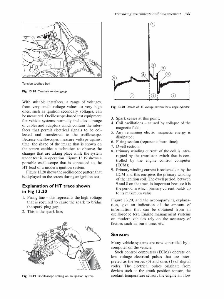
With suitable interfaces, a range of voltages,from very small voltage values to very highones, such as ignition secondary voltages, canbe measured. Oscilloscope-based test equipmentfor vehicle systems normally includes a rangeof cables and adaptors which contain the inter-faces that permit electrical signals to be col-lected and transferred to the oscilloscope.Because oscilloscopes measure voltage againsttime, the shape of the image that is shown onthe screen enables a technician to observe thechanges that are taking place while the systemunder test is in operation. Figure 13.19 shows aportable oscilloscope that is connected to theHT lead of a modern ignition system.
Figure 13.20 shows the oscilloscope pattern thatis displayed on the screen during an ignition test.
Explanation of HT trace shownin Fig 13.20
1. Firing line – this represents the high voltagethat is required to cause the spark to bridgethe spark plug gap;
2. This is the spark line;
3. Spark ceases at this point;4. Coil oscillations – caused by collapse of the
magnetic field;5. Any remaining electro magnetic energy is
dissipated;6. Firing section (represents burn time);7. Dwell section;8. Primary winding current of the coil is inter-
rupted by the transistor switch that is con-trolled by the engine control computer(ECM);
9. Primary winding current is switched on by theECM and this energises the primary windingof the ignition coil. The dwell period, between9 and 8 on the trace, is important because it isthe period in which primary current builds upto its maximum value.
Figure 13.20, and the accompanying explana-tion, give an indication of the amount ofinformation that can be obtained from anoscilloscope test. Engine management systemson modern vehicles rely on the accuracy offactors such as burn time, etc.
Sensors
Many vehicle systems are now controlled by acomputer on the vehicle.
Such control computers (ECMs) operate onlow voltage electrical pulses that are inter-preted as the zeroes (0) and ones (1) of digitalcodes. The electrical pulses originate fromdevices such as the crank position sensor, thecoolant temperature sensor, the engine air flow
12
34
5
67
89
101112
KOR 21– 55
Tension toothed belt
Fig. 13.18 Cam belt tension gauge
ST8018BO
Fig. 13.19 Oscilloscope testing on an ignition system
7 6
89
5
2
1
3
4
Fig. 13.20 Details of HT voltage pattern for a single cylinder
Measuring instruments and measurement 341

sensor and many others. The sensors on avehicle measure some quantity, such as speedor position and then convert the quantityinto an electrical signal. The electricalsignal that is produced is an accurate repre-sentation of the variable being measured.Sensors play a vital part in the operation ofvehicle systems and the maintenance and test-ing of them is a major element of the work ofa vehicle technician.
Figure 13.21 shows an oscilloscope screendisplay of the voltage pattern obtained at theoutput terminals of a throttle position sensor.A separate window on the screen shows anideal pattern that is stored in test equipmentmemory. This is the lower trace in Fig. 13.21.The upper trace shows the voltage patternobtained from a single throttle operation.This trace is obtained by moving the throttlefrom the closed position to the to fully openposition.
1. show the actual test pattern showing a defec-tive throttle position sensor trace, and
2. the voltage spikes in a downward directionindicate a short circuit to earth or a break inthe resistive strip in the sensor.
The lower trace shows the pattern for a sensorin good condition. The trace between 5 and 4 is
obtained by a full operation of the throttle fromclosed to fully open and back to closed. Thevoltage at 5 represents the throttle closed posi-tion, the section marked 6 shows the voltageincreasing smoothly to the throttle fully openposition and the section marked 3 shows thevoltage decreasing smoothly back to the throttleclosed position at 4.
13.5 Digital multi-meter
Multi-meters are electrical measuring instru-ments (meters) that can be set to read voltage,current, resistance, frequency, etc. Digitalinstruments are most suited to testing modernvehicle systems because they have the highimpedance (internal resistance) that is requiredfor testing circuits that contain sensitiveelectronic components.
Using a multi-meter
Figure 13.22 shows a sensor that is built intoan engine oil dipstick. The sensor, marked 3, isa small length of fine wire that has a hightemperature coefficient of resistance whichmeans that small changes in temperatureproduce large changes in resistance. The resis-tance of the sensing element is 7 ohms at roomtemperature.
When the control unit passes a currentof 200mA through the sensing element, fora period approximately 2 seconds, the sensingwire is heated and this produces an incr-ease in resistance. This increased resistance
1
7 2
6
5
3
4
1.2.
3.
4.5.6.7.
Defective TPS pattern.Spikes in a downward direction indicate a shortto ground or an intermittent open in the resistivecarbon strips.Voltage decrease identifies enleanment (throttle plateclosing).Minimum voltage indicates closed throttle plate.DC offset indicates voltage at key on, throttle closed.Voltage increase identifies enrichment.Peak voltage indicates wide open throttle (WOT).
Analysis of voltage trace for a potentiometer-type throttleposition sensor
Fig. 13.21 Testing a throttle position sensor
Low oil sensor circuit diagram1 – Connector (to loom)2 – Trimming resistor3 – Sensor (fine wire with a high temperature coefficient of resistance)
1
32
OR /33C/10
Fig. 13.22 Low oil sensor
342 A practical approach to motor vehicle engineering and maintenance

leads to a voltage increase across the sensorterminals.
If the oil is level is correct, the sensor is in oiland the heat is dissipated. Any voltage increasecaused by the electrical pulse is small. If the oillevel is low, the sensor wire will be in air. Thetemperature increase from the electrical pulsewill be large and the voltage across the sensorterminals will be high.
The voltage across the sensor terminals ismeasured by the control unit. If the voltageincrease is greater than the set value that is keptin the control unit memory, the ‘low oil’ warn-ing light is switched on.
Testing a low oil sensor by meansof a digital multi-meter
A typical use of the multi-meter is to measure theresistance of a sensor because, in many cases, thisgives a guide to its electrical condition.
In Fig. 13.23(b), the ignition has beenswitched off and the cable connector has beendetached from the sensor. The multi-meter hasbeen set to measure resistance in ohms and themeter probes are connected to the two sensorpins. In this case, the resistance should liebetween 6.4 ohms and 7.6 ohms. The test shouldbe done quickly, because the current from theohm-meter will heat the sensing element andchange the resistance. If this test is satisfactory,the sensor should be re-connected. The multi-plug is then disconnected at the ECM and theohm-meter probes are applied to the appropri-ate pins on the multi-plug, in this case, pins 10and 11, as shown in Fig. 13.23(c). The resistancereading at this point should be between6.4 ohms and 8.6 ohms, the higher figure beingattributable to the length of cable between thesensor and the multi-plug.
Applications of number
Approximations and degrees of accuracy
Significant figures
Measurements and calculations often producenumbers that are more useful when they arerounded to a certain number of significant fig-ures. For example, the swept volume of a certainsingle cylinder engine is 249.94 cc. For manypurposes, this figure would be rounded to 3significant figures, to give 250cc.
The rule for rounding to a certain number ofsignificant figures is: ‘‘If the next digit is 5 ormore, the last digit is increased by 1. A zero in the
middle of a number is counted as a significantfigure, for example, 3.062 to 3 significant figuresis 3.06.’’
Decimal places
Numbers can be rounded to a certain number ofdecimal places, dependent on the requireddegree of accuracy. For example, 3.56492,rounded to 2 decimal places, becomes 3.56.
The rule for decimal place approximationsis; ‘‘If the next number (digit) is 5 or more, theprevious digit is increased by 1.’’
(a)
(b) Resistance at sensor 6.4 Ω to 7.6 Ω
OR /33C/20
10 111 172 3 4 5 6 7 8 9 12 13 14 15 16
(c) Resistance at ECM 6.4 Ω to 8.6 Ω
OR /33C/22
OR /33 C/ 25
ONOFF
OFFON
2000 Ω
500 V~
200 V
200 kΩ+20 A
C
Fig. 13.23 Resistance check of a sensor
Measuring instruments and measurement 343

Examples
1. The test data for a throttle position sensorspecifies a voltage of 2.50 volts for the halfopen throttle position. A test with a digitalmeter gives a voltage reading of 2.496 voltsfor the half open throttle position. Does thismean that the sensor is faulty?The answer is probably not, because the testdata is given to 2 places of decimals. Whencorrected to 2 decimal places, the digitalmeter reading becomes 2.50 volts which isas it should be.
2. The maximum permitted diameter of acertain crankpin is given as 43.01mm.When measured with a micrometer, thediameter is found to be 43.009mm. Is thisacceptable?Yes. The test data is given to 2 decimalplaces. When the measured reading of43.009mm is rounded to 2 decimal places, afigure of 43.01mm is produced and this isexactly the same as the quoted figure.
Limits
Dimensions of components are normally givenin the following form:
Crankshaft main bearing journals: 53.970mm to
53.990mm
Crankshaft end float: 0.093mm to 0.306mm
Valve length: 107.25mm to 107.35mm.
In these cases, the larger figure is known as theupper limit and the smaller figure as the lower
limit. The difference between the upper limitand the lower limit is known as the tolerance.
To calculate the tolerance, the smaller dimen-sion is subtracted from the larger. For example, inthe case of themain bearing journal, the toleranceis 53:990mm 53:970mm ¼ 0:020mm.
These tolerances allow for slight variations inmeasurements at the manufacturing stage, andalso variations in dimensions that arise fromwear in use.
Fits
The terminology of engineering fits is based onthe dimensions of a shaft and a hole into whichthe shaft is inserted.
When the shaft is slightly smaller than thehole to which it is to be fitted, the result isknown as a clearance fit. The clearance is
required for lubrication and thermal expansionpurposes.
When the shaft is slightly larger than the holeto which it is to be fitted the result is known asan interference fit. Interference fits are usedwhere the shaft is to be firmly secured by thematerial surrounding the hole.
Examples of the two types of fit are shown inFig. 13.24.
With a floating gudgeon pin, the pin is aclearance fit in the small end bush. The gud-geon pin is located in the piston by means ofcirclips that fit into grooves on each side ofthe piston.
In the semi-floating gudgeon pin arrange-ment, the gudgeon pin is an interference fit inthe small end eye of the connecting rod. Thegudgeon pin is held in place by the strainenergy in the materials. At the fitting stage,the gudgeon pin is either pressed into the con-necting rod using a hand operated screw pressor the connecting rod is heated to make thesmall end eye expand so that the gudgeon pinmay be inserted. When the assembly coolsdown, the gudgeon pin is firmly held in thesmall end eye.
Angular measurement
Examples of angles that occur in motor vehicledimensions as shown in the following table:
Specification of angles
The degree is the basic measurement of angle.As there are 360 degrees in a complete circle, formore accurate measurement, a degree is sub-divided into 60 minutes.
A degree is denoted by the small zero above thenumber, i.e., 1.
A minute is denoted by a small dash above thenumber, i.e., 50.
Steering Angle (Approximate)
Camber angle 1 260
Castor angle 2 110
King pin inclination 3
Toe-out on turns Outer wheel 20 Inner wheel
25 300
Engine Angle (approximate)
Spark ignition – static advance 12 before TDC
Valve timing – inlet valve
opens
8 before TDC
Diesel fuel pump – start of
injection
15 before TDC
344 A practical approach to motor vehicle engineering and maintenance

The camber angle given in the Table is 1 260;this reads as one degree, twenty-six minutes.
Figure 13.25 shows two examples of angu-lar measuring devices in use. In Fig. 13.25(a)a 360 protractor is attached to the timinggear of a diesel in order to set the injectiontiming. In Fig. 13.25(b), the angle is readfrom the protractor on the track alignmentgauges.
Learning activity answer. Figure 13.8.
Ans. (a) 10.61 mm
Micrometer size 0–25 mm
Reading:. Major divisions ¼ 10 1 ¼ 10 mm. Minor divisions ¼ 1 ¼ 0:5 mm. Thimble divisions ¼ 11 ¼ 0:11 mm. Total ¼ 10:61 mm
Ans. (b) 45.66 mm
Micrometer size 25–50 mm
Reading:. Major divisions ¼ 20 1 ¼ 20 mm. Minor divisions ¼ 1 0:5 ¼ 0:5 mm. Thimble divisions ¼ 16 ¼ 0:16 mm. Total 45.66 mm
Ans. ( c ) 90.56 mm
Micrometer size 75–100 mm
Reading:. Major divisions ¼ 15 1 ¼ 15 mm. Minor divisions ¼ 1 0:5 ¼ 0:5 mm. Thimble divisions ¼ 6 0:01 ¼ 0:06 mm. Total 90.51 mm
Ans. (d) 6.31 mm
Micrometer size 0–25 mm
Reading:. Major divisions ¼ 5 1 ¼ 5 mm. Minor divisions ¼ 0. Thimble divisions ¼ 31 0:01 ¼ 0:31. Total 5.31 mm
Pin diameter slightlysmaller than innerdiameter of small
end bush
Pin diameter slightlylarger than innerdiameter of small
end eye
Clearance fit Interference fit
Semi floating gudgeon pin
Connecting rod
Gudgeon pin
Big endbearing shell
Floating gudgeon pin
Gudgeon pin
Circlip
Small end bushSmall end ofconnecting rod
Gudgeon pins – clearance & incerference
Fig. 13.24 Floating and semi-floating small ends – clearance and interference fits. (Reproduced with the kind permission of Bowers
Metrology Group.)
Measuring instruments and measurement 345

Self assessment questions
1. Correct the following figures to 2 decimal
places:
(a) 43.001
(b) 0.768
(c) 5.887
2. Correct the following figures to the specified
number of significant figures:
(a) 19.28 to 3 significant figures
(b) 2.034 to 3 significant figures
(c) 337.9 to 3 significant figures
3. The capacity of a certain engine is calculated
to be 1998 cm3. For descriptive purposes,
this figure is expressed in litres. Calculate
the engine capacity in litres, correct to 2
significant figures.
4. 43 bolts, priced at 45.6 pence each, are to be
added to an account. Calculate the total
amount for the 40 bolts, correct to nearest
1 penny. Give the answer in pounds and
pence.
5. Figure 13.26 shows a feeler gauge being used to
check the gap in a piston ring.
In order to perform this check:
(a) the piston ring should just be pushed into
the cylinder
(b) the piston ring should be gently pushed into
the cylinder using a piston as a guide to
ensure that the ring is at right angles to
the axis of the cylinder
(c) the ring gap must not exceed 0.001 mm
(d) it does not matter if the ring is tilted in the
cylinder
6. Figure 13.27 shows a dial gauge that is set
up to measure the end float on an engine
crankshaft.
End float is important because:
(a) it allows space for lubrication of the crank-
shaft thrust bearings
(b) it provides free travel at the clutch pedal
(c) it helps to keep the timing gears in alignment
(d) it allows oil to be sprayed onto the cylinder
walls to lubricate them
7. A crankpin has a diameter of 58.20 mm and
the big end bearing that is fitted to it has
an internal diameter of 58.28 mm. The clear-
ance between the crankpin and the big end
bearing is:
(a) 1.0013 mm
(b) 0.008 mm
(c) 0.08 mm
(d) 0.48 mm
8. Figure 13.28 shows a feeler gauge marked 5 being
used to check the clearance between the cam
marked 4 and the cam follower.
This clearance is known as the valve clearance
and it is checked when:
(a) the cam is in the fully closed position
(b) when the engine is at the recommended
temperature and the valve is in the fully
closed position
190
200
210 220 230 240250
260270
280
290
300
310
320
330
340
350
0
102030
40
50
6070
80
90
100
110
120
130
140
150160
170180
OR 21–80
(a)
K
Angle readhere
(b)
6NC 606
Fig. 13.25 Angular measurement on motor vehicles
TR 21–234 K
Fig. 13.26 Checking a piston ring gap
346 A practical approach to motor vehicle engineering and maintenance

(c) the valve is fully open
(d) the cam is at any position between valve
fully open and valve fully closed
9. The crankpin shown in Fig. 13.29 is measured at
A, B, C and D.
Dimensions A and B are taken to determine
taper, and dimensions C and D to determine
ovality. In this case the dimensions are:. A ¼ 42:99 mm. B ¼ 42:75 mm. C ¼ 42:99 mm. D ¼ 42:60 mm.
The taper on this crankpin is:
(a) 0.39 mm
(b) 0.24 mm
(c) 0.15 mm
(d) 0.01 mm
10. The ovality on this crankpin is:
(a) 0.24 mm
(b) 0.00 mm
(c) 0.39 mm
(d) 0.15 mm
11. Figure 13.30 shows the positions in an
engine cylinder at which measurements of
diameter are taken in order to assess wear.
The measurements are taken in line and at
right-angles to the crankshaft, at the three
levels shown. The third measurement is
taken at the lowest extent of piston ring
travel. The terms ovality and taper are used
to describe the condition of the cylinder
bore. Ovality is the difference betweeen a
and b, and taper is the difference between
the largest diameter at the first measure-
ment and the smallest diameter at the third
measurement.
In an example, the following dimensions were
recorded:. First measurement, a ¼ 74:22 mm;
b ¼ 73:95 mm,. Second measurement, a ¼ 74:19 mm;
b ¼ 74:00 mm,. Third measurement, a ¼ 74:00 mm;
b ¼ 73:97 mm.
The maximum ovality is:
(a) 0.22 mm
(b) 0.19 mm
(c) 0.27 mm
(d) 0.03 mm
12. The taper is:
(a) 0.25 mm
(b) 0.03 mm
(c) 0.19 mm
(d) 0.27 mm
0
10
20
30
4050
60
70
80
90
KER 21–58
Fig. 13.27 Checking crankshaft end float
1 4
3
2
5
RM1616
Fig. 13.28 Checking valve clearances
A B
Crankpin Crankpin
Web Web
C
D
Fig. 13.29 Crankshaft measurement
b
a
1st Measurement
2nd Measurement
3rd Measurement
Fig. 13.30 Cylinder bore measurement
Measuring instruments and measurement 347

14Organisations and qualifications
Topics covered in thischapter
Organisations in the motor trade
Qualifications and careers
14.1 Qualifications
It is unfortunate that training and educationtend to be treated as separate activities becausethis leads to difficulty when one is attemptingto choose a course of study or training. How-ever, there are many fundamentals of motorvehicle engineering where the distinctionbetween training and education cannot sensi-bly be made. With valve timing of an engine, itis essential to understand cycles of engineoperation, for example, the four stroke cycle.The knowledge required is known as engine tech-nology and is generally considered to be educa-tion and therefore is part of the syllabus forcourses such as City and Guilds ProgressionAward, BTEC First Diploma and Certificateand similar qualifications. The actual setting ofthe valve timing is a practical task and learninghow to do it is considered to be training. Theinstruction and practice that leads to becomingproficient at the task is also considered to betraining and is considered to be part of theNational Vocational Qualification (NVQ).The outcome of this rather artificial distinctionbetween education and training is that educa-tional courses contain much that contributes toones ability to be a vehicle technician, whilepractical training courses for NVQ also con-tain much that is of educational value and, as aresult, there are several routes that people canfollow in order to qualify as a motor vehicletechnician.
14.2 Modern motorvehicle qualifications
National Vocational QualificationNVQ – Scottish VocationalQualification-SVQ
A list of skills that are required for competentperformance of the tasks involved in maintenanceand repair of vehicles has been devised and theseskills are known as National Occupational Stan-dards, a typical example being, Carry out routinevehicle maintenance. These Occupational Stan-dards are used to design qualifications such as theNVQ. Because the work of a motor car techniciandiffers in some respects from that of a heavy vehicletechnician, the training programme and coursecontent is not the same and NVQs have beendesigned to cater for these differences. The sameis true of other motor vehicle occupations, such asAuto Electrical Technician, Vehicle Body RepairTechnician, Parts Department technician, etc.
Levels
In the school years, levels of attainment tend tobe expressed in terms of year 2, year 6, etc., butin post school training and education, the use ofyears as a description of a degree of difficultyinvolved in some learning step, is not appropri-ate and the training and education courses areclassified in Levels. The result is that NVQs areavailable at several Levels, the main ones beingat Levels 1, 2 and 3.
Studying for NVQ
To qualify for NVQ, it is necessary to demon-strate competence, namely ability to perform agiven task in a normal work situation. However,as already explained in the example of valve

timing, the performance of a practical task oftenrequires an underpinning knowledge of technol-ogy. The result is that courses of study for NVQconsist of a balanced program that takes placeon the job (in a workshop), for the practical andoff the job (in a classroom), for the underpin-ning knowledge. NVQs in Motor Vehicle Main-tenance and Repair certainly require a gooddeal of underpinning technical knowledgetogether with practical training and courses ofeducation and training are designed to cater forthese factors.
Modern apprenticeships
Modern apprenticeships provide paid employ-ment, practical training and further education.During the apprenticeship, trainees must studyfor NVQ and Key Skills and a Technical Certi-ficate, such as City and Guilds of BTEC.
There are two levels of apprenticeships;foundation for beginners and the trainingand education programme normally lasts forapproximately 1 year. The other level is theadvanced apprenticeship, which lasts forapproximately 2 years.
Foundation modern apprenticeship
This first level of apprenticeship trains appren-tices for Level 2 NVQ and the associatedKey Skills. In addition, a Technical Certificateis studied and this may be a BTEC First,City&Guilds or Institute Of motor Industrycertificate.
Advanced modern apprenticeship
Advanced Apprenticeships are designed to lastfor 2 years. They prepare trainees for Level 3NVQ and Key Skills and a Technical Certifi-cate, such as BTEC National or similar educa-tional qualification is studied. Apprenticeshipsshould, in future, provide the most attractiveand efficient route to qualification and employ-ment in the vehicle maintenance and repairindustry.
Courses in colleges
Many Further Education Colleges providecourses of Motor Vehicle Studies. The coursesvary from those for beginners, such as the City& Guilds Progression Award, to main streamcourses for BTEC National Certificates and
Diplomas. Many of these courses are linked toemployers so that the students gain work experi-ence and this practical work, plus work doneat college, may be taken into account whenmaking a later claim for NVQ. For studentswho opt for study in a Further EducationCollege, as opposed to School 6th form, theBTEC National and Higher National pro-grammes may provide a route into Universityeducation.
Courses in secondary schools,technology colleges, etc.
Over the past few years, a number of secondaryschools have offered motor vehicle courses and,with the renewed emphasis on vocational educa-tion, such courses are likely to become morewidely available.
This book is designed for Levels 1 & 2 ofcurrent training and education programmesbut there are elements that extend into theLevel 3 region of some topics. The text showsa large number of engineering concepts andit should help readers to make links betweenpractical work and other subjects, such asscience and number work, and thus assist inproviding students with a balanced educationalexperience.
14.3 Career Prospects
When embarking on a career in the vehiclerepair and maintenance industry, thoughtsabout future jobs may not be uppermost inone’s mind. As one’s career progresses thismay change and it is useful to have an insightinto the types of jobs that may be open topeople who have trained as technicians. Thefollowing list gives an indication of the typesof jobs that are often taken by people whostarted work as trainees or apprentices andwho, through gaining experience and qualifica-tions, equipped themselves for promotion:
. Foreman
. Technical receptionist
. Service manager
. Branch manager
. Training instructor
. Teacher/lecturer
. Insurance engineers and assessors
. Transport managers.
Organisations and qualifications 349
How to get there
There are approximately 30 000 businesses,large and small, in the UK, that carry out vehi-cle repair and maintenance. There are, there-fore, many opportunities for traineestechnicians to advance to more senior positions,if they so desire. Holders of the jobs in the abovelist need management skills and these are oftentaught through specialised managementcourses. Management studies are also includedin higher-level qualifications such as HigherNational Certificates and Diplomas. A wellpresented curriculum vitae (CV) is likely to bean asset when applying for more senior posi-tions. Apprenticeships and other opportunitiesfor beginners are likely to be advertised andpromoted through the career service. Collegecourses that contain an element of work experi-ence often lead to employment – it is probably agood idea to shop around in your area to seewhat courses are on offer.
14.4 Motor industryorganisations
The Institute of the Motor Industry (IMI), andthe Institute of Road Transport Engineers(IRTE), are two of the engineering/managementinstitutes that many people engaged in motorvehicle maintenance and repair belong to. Theseinstitutes have regional centres that arrangelectures and other events relating to the indus-try. These events provide an opportunity tomeet people from many different companies inan informal setting, in addition to allowing anopportunity to help people keep abreast ofdevelopments. Two magazines, Motor IndustryManagement published by the IMI and RoadTransport Engineer, published by the IRTE,advertise posts nationally, and the local pressnormally carries advertisements about jobvacancies in their areas.
350 A practical approach to motor vehicle engineering and maintenance

Index
acceleration devices, 91acceleration enrichment, 94acceleration pump, 92accountability, 7actuator, 98, 100, 196, 198, 238, 239,
275, 297, 298aeration, 66, 181air bleed compensation, 90air control valve, 129–30, 132,
133, 138air cooled diesel engine, 60–2,
64, 78air cooling
advantages, 64disadvantages, 64
air filterelement, 103, 128
air flow meter, 98, 100, 130–1, 134air flow sensor, 130, 235, 341–2air intake manifold, 96, 130, 132air intake system, 129air supply
practical assignment, 139temperature control, 128–30
air suspension, 178air/fuel ratio, 85, 89, 94, 98, 100, 102, 104, 136,
273alternating current (AC), 230, 249alternator
component parts, 251cooling fan, 253field decay voltage, 320general principle, 248output, 253, 320output tests, 253
alternator rectifier, 250ampere-hour, 246anti-dieseling valve, 95anti-freeze, 75–6, 302anti-lock braking system (ABS), 195
modulator, 197, 198, 239, 240wheel speed sensor, 196
anti-roll bar, 177, 178atomization, 85, 89, 90, 118authority, 7automatic transmission, 147, 153auxiliary air device, 29axial flow fan, 62axle casings, 159–60, 163, 164axle shaft, 163–5
axlesfully floating, 164–5practical assignment, 168semi-floating, 163–4three-quarter floating, 164
baffle plates, 47ball-joints, 200, 202, 203, 211, 212–13ballast resistor, 280battery
capacity, 246, 247charging, 246, 247construction, 244installation, 245reserve capacity, 247testing, 247–8
battery plates, 245–6bearings
alternator, 253ball and roller, 43, 165combined radial and one-way thrust, 166double-row journal, 165journal, 41, 42, 165, 166needle roller, 166, 209parallel-roller journal, 166plain, 39, 165single-row deep groove radial, 165–6taper roller, 163–4, 166, 213types, 165–6
bi-metal elements, 77, 78bi-metal spring, 93, 129bi-metal strip, 94, 318, 323, 324bleeding
brakes, 198fuel system, 114
Bluecol hydrometer, 76, 77Boolean logic, 233Bosch, 238, 269boundary friction, 42brake adjustment, 192brake fluid, 195brake fluid reservoir, 190brake line pressure, 196, 197brake pipes and hoses, 191brake pressure control valve, 194brake servo, 191brakes
bleeding, 198hydraulic operation, 187types, 186–7

braking efficiency, 195braking systems
check, 198practical assignment, 198split, 189
brush box, 252brushes, 251bulbs, 309Burroughs type tension gauge, 253business – line organization chart, 7bypass filter system, 51
cable sizes, 318calibration, 94, 113, 114, 115calorific value, 85cam and peg steering box, 209cam profile, 26, 32camber, 203, 204, 206, 220, 221camshaft, 22, 29, 87camshaft drives, 26, 29, 31capacitor (condenser), 262
testing, 287carbon monoxide, 85, 128, 135carburation, 89carburettor
fixed choke, 89variable-choke, 94–5
cartridge filter, 52castor action, 206catalytic convertor, 100, 135–7cavitation, 75centrifugal advance mechanism, 278, 290, 291centrifugal fan, 62centrifugal filter, 53centrifugal pump, 67, 68choke, 89, 94, 104circuit breakers, 302, 318, 323circuit diagram
alternative symbols, 233, 249, 314circuit materials, 227circuit protection devices, 298, 318, 320circuit symbols, 230, 231, 233, 249, 314, 316circuit testing, 228clerk two-stroke cycle, 15clutch
adjustment, 144–5diaphragm-spring, 141faults, 145fluid, 145hydraulic linkage, 144mechanical linkage, 144multi-plate, 145multi-spring, 141operating mechanisms, 144removal, 167
clutch drag, 142, 145clutch judder, 142clutch linings, 5clutch slip, 145clutch vibration, 145coefficient of friction, 143coil HT output, 261, 262, 272, 273, 279, 287,
288, 289, 341coil ignition systems
fault finding principles, 285coil polarity, 262coil spring, 171cold starting, 85, 95, 279cold starting devices, 92colour code, 315combustion chamber, 17, 20, 26, 27, 28, 30, 34,
36, 58, 96, 98, 100, 101, 108, 118, 119, 128,130, 260, 280, 282, 293, 327
combustion processdiesel engine, 20, 26petrol engine, 20, 26phases, 28
common rail (diesel fuel system), 121compensator, 188compression ignition engine
two-stroke, 18, 19compression pressure, 19, 37, 238, 281, 331, 338compression ratio, 20conductivity, 137, 227, 229, 286connecting rod, 36connectors, 321constant-velocity (CV) joint, 156, 157, 158contact breaker, 274, 284, 289, 292contact breaker less ignition system, 274, 284contact breaker type distributor (servicing), 292contact points
checking, 286controller area network (CAN), 238, 239cooling air circulation, 60cooling fans
automatically-controlled, 73directly driven, 73drives, 73electrically driven, 71flexible blades, 71free-wheeling, 73, 154surrounded by cowl or attached toradiator, 73
swept tips, 72torque-limiting, 74variable-pitch, 74variable speed, 73, 74
cooling systembuild up of deposits, 76corrosion, 75
354 Index

fault chart, 77fully sealed, 70liquid, practical assignment, 81, 82pressurized, 69semi-sealed, 70types, 60water flow, 67
corrosioncooling system, 75exhaust system, 137
crankcase assembly, 37crankshaft, 39crown wheel and pinion, 160–3customer categories, 8customer’s collection points, 10cutting out, 293cycles of operation, 15cylinder arrangements, 21, 22, 23cylinder block, 37cylinder head
exploded view, 35function, 34removing and refitting, 55tightening sequence, 34
cylinder liners, 38
damper, 94, 181data (control bus), 239, 241decarbonising, 294degas system, 70delegating, 8delivery valve, 112detonation, 58, 293diagnostic equipment, 134, 235dial test indicator (DTI), 162, 337, 338diesel air mixture, 20diesel engine
air-cooled, 60, 61, 62, 64, 78combustion process, 26two-stroke, 19, 24
diesel fuel systems, 108, 109differential, 162digital electronic ignition, 264, 271digital meter, 228, 229, 342, 343diode, 229, 230, 231, 249, 250direct current (DC), 230, 249direct injection system, 27, 28direction indicator lamps, 309, 312disc brakes, 187disc filter, 53discipline, 7distributor cam, 274, 279distributor drives, 275, 277distributor shaft, 263, 275, 278distributorless ignition system, 266, 272
dog clutch, 148–51doping, 227, 229DPA fuel injection pump, 110, 115drag, 41, 74, 92, 200drag link, 200, 209drive belt tension, 253, 254drive pulley, 73, 250, 252, 253drive shaft, 49, 155, 156, 157, 158, 162, 213, 277drum brakes, 186, 188, 192dry friction, 41, 42dry sliding friction, 41, 42dunlop optical alignment gauge, 206dwell angle, 275, 276, 289, 291, 292dwell variation, 277dynamic ignition timing, 289, 290
earth circuit, 257EEPROM, 236, 238electric current
chemical effect, 243electric motor effect, 225electric motors, 71, 88, 179, 225, 226, 297, 299,
306, 308electric shock, 272, 284, 285, 290, 312electrical fuel pump, 88electro–chemical effect, 243, 244electrolyte, relative density, 246, 247electromagnetic induction, 225electromagnetic waves, 224electromotive force (EMF), 225electronic control unit (ECU), 48, 130, 132,
196–7, 312, 327electronic devices, 240, 249, 263, 265electronic ignition system
amplification stage, 231circuit testing, 228power switching stage, 230, 232waveform processing, 196, 262
electronic module, 236, 269electronic type distributor, 271electronics, 227, 229emission control, 101, 128, 134, 239engine block components, 12engine capacity, 21engine components
functional requirements, 16internal, 14, 45layout, 11, 12location, 12
engine control module (ECM), 341engine core plugs, 78engine management systems (EMS), 100, 105,
255, 341engine oil, SAE viscosity classification,
43–5
Index 355

engines, 11epicyclic gear train, 153–4ethylene-glycol anti-freeze solution, 75excess fuel device, 112exhaust catalyst, 100, 101, 107exhaust emissions testing, 137exhaust gas analyser, 137exhaust gases
recirculation (EGR), 101–2exhaust system
broken or damaged, 135component parts, 135corrosion, 137maintenance, 137practical assignment, 139
exhaust valve, 18, 29expansion tank, 70, 71
fan belts, 75fans, 62, 71fast-idle, 94, 125, 130fault codes, 238fault tracing, 269, 284, 298, 302feeler gauge, 331field, 227final drive
hypoid bevel, 161lubrication, 164practical assignment, 168servicing and adjustments, 161spiral bevel, 160straight bevel, 160worm and wheel, 161
firing interval, 22firing order, 21, 22–3, 289flasher unit, 312, 315flat spot, 92, 94Fleming’s rule, 226fluid flywheel, 145, 146fluid friction, 41, 42flywheel, 39, 141–5, 265four cylinder in-line engine, 13, 22, 62four stroke cycle of operations, 15,
17, 18four wheel drive, 12, 205free-wheeling device, 73, 154friction, 40–3, 141, 142, 143friction brakes, 186friction pad wear indicator, 193friction plate
construction, 142materials, 143
front hub assembliesdriving hubs, 213non-driving hubs, 213
front wheel drive, 213–14fuel consumption, excessive, 102, 293fuel filter, 86, 87, 108fuel injection unit, 86, 96fuel lift pump, 86, 87fuel pipe lines, 87fuel system
layout, 86fuel tank, 86, 88full-flow filter, 51, 53full-flow system, 51full load, 101full wave rectifier, 249, 250fuses and fuseboxes, 318,
320, 321
gas-pressurized dampers, 181gear lever
direct acting, 152remote acting, 152
gear pump, 49gear selection mechanism, 151gearbox
baulk ring synchromesh, 150, 151constant load synchromesh, 150constant mesh, 149, 153interlocking mechanism, 152path of drive, 151removal and refitting, 66sliding mesh, 148–9synchromesh, 149, 150, 151
gears, types, 147
half-wave rectifier, 249–50hall effect
distributor, 264ignition system, 264pulse generator, 271
hall element, 265hand-brake (parking brake), 188header tank, 63, 64, 66headlamp
alignment checking, 311bulbs, 309circuit, 314dipping, 311–12
heat losses, 80heat path, 282heat sink, 230, 252heat transfer, 58, 80heater plugs, 119–21heating and ventilation, 78–9height corrector, 177, 178helical gear, 148–9hesitation, 293
356 Index

high tension, HTcables, 273leads, 288sparking, 285, 286
horizontally opposed cylinders, 21, 22hotchkiss drive, 155, 156hydraulic accumulator, 178, 197hydraulic cylinder, 187, 188hydraulic fluid, 187hydraulic system, 145, 187, 198hydraulic tappet, 32, 337hydro-elastic suspension, 176hydro-pneumatic suspension, 176, 177hydrocarbons, 85, 101, 128, 135hydrogas suspension, 176–7hydrometer, 76, 77, 246, 247
idle air control, 130idling, 26, 71, 90, 91, 104, 105, 133, 154idling mixture, 91, 104idling speed, 104ignition circuit, 240, 262, 269, 280, 294ignition coil, 240, 261, 264, 267, 287ignition system
fault tracing, 269, 284function, 274induction type coil, 260practical applications, 288visual checks, 285
ignition timingsetting, 26
independent front suspension, 173, 201, 203independent rear suspension, 172, 175indirect injection system, 28injector pump, 108, 110, 118injectors, 117, 118, 123inlet manifold, 24, 86, 89, 90, 91, 94,
97, 120inlet valves, 29in-line cylinders, 22in-line engine, 13, 21insulators, 227intake manifold, 96, 130, 132integrated circuits, 232intermittent fault, 295internal combustion engine, 11
job card, 9joule, 80journal bearing, 165, 166jump starting, 320
king pin inclination, 203, 204, 206knock sensor, 267, 268knocking, 293
lambda, , 100, 136, 137laycock overdrive, 154layshaft gears, 148, 149lead acid battery, 244leaf spring, 170levelling valves, 178lift pumps, 86, 87, 88, 108, 110, 114,
115, 116light emitting diode (LED), 230, 231light vehicles, 11, 200, 215lighting
regulations, 309liquid cooling, 60, 62, 82liquid crystal (LCD), 229, 325load dump, 320logic devices, 232, 233lost spark system, 266low power, 293lubrication system
by-pass system, 51components in, 45delivery valves and pumping elements, 114dry sump, 45, 54final drive, 155, 160, 168full-flow system, 51total loss, 45, 54wet sump, 45
magnetic field, 224–7, 229, 250, 251, 261, 262,275, 288, 341
magnetism, 224master cylinder
tandem, 190mechanical lift pump, 87, 88meters, 228methanol-based anti-freeze, 76microprocessor, 266mineral deposits, 75misfiring, 293mixture correction, 90mixture enrichment, 90, 94modulator, 196, 197, 198, 239, 240motor trade business, 354motor vehicle, engine terms,
definitions, 16moving coil meter, 228, 229multi-cylinder engine, 22, 39, 274multi-element injection pump, 112multi-point injection, 96, 99, 100multiplexing, 240, 241mutual induction, 288
national vocational qualifications (NVQ)assessment sheets, 55glossary of terms, 351
Index 357

needle valve, 87, 118, 119, 123negative off-set, 205negative steering roll radius, 205negative temperature coefficient, 77, 227, 324neon test lamp, 285neutral pressure zones, 79nickel-iron battery, 244nitrogen oxides, 85, 128, 135
octane rating, 294off-set, 92, 203, 205, 289, 310ohm-meter, 286, 288, 343ohm’s law, 227, 228oil coolers, 54oil filters, 45, 50–3oil function, 45oil galleries, 45oil level indicator, 48oil pump, 45, 48oil seals, 39–40, 164oil wedge, 46oldham coupling, 275opposed piston, 21oscilloscope, 262, 263, 269, 270, 271, 272, 285,
340, 341, 342otto four-stroke cycle, 15over-cooling, 59over-heating, 58, 118, 120overdrive, 153, 154, 155oxygen sensor, 100, 101, 136, 137, 138, 243
panhard rod, 175pawl-type free-wheel, 113permanent magnet motor, 258, 299, 308permanent magnets, 88, 196, 224, 297, 299,
300, 308petrol air mixture, 16, 17, 20, 89petrol engine, combustion process, 26petrol fuel, 85, 96, 102, 105, 126petrol injection system
multi point, 96, 99, 100single point, 96, 98
phasing, 113–15pinking, 267, 293–4pintaux nozzle, 119pintle, 118, 119pipelines, 86piston, 17, 18, 21, 22, 26, 36, 37piston rings, 37pivot points, 205plenum chamber, 61, 78, 79plug reach, 282, 283plunge joint, 158pneumatic spring, 177pn junction, 229, 230, 231, 232
polarity, 262, 321policy
company, 7safety, 2
potentiometer, 130, 345powerbus, 241pre-ignition
causes, 58, 281, 293, 294pressure cap
testing, 339pressure regulator, 96, 97, 98, 99pressure-relief valve, 50, 88pressure valve, 69, 71, 88primary circuit, 261, 269, 286primary winding, 260, 261, 262, 263, 273, 275,
276, 280, 287, 291, 341problem solving, six step approach,
255, 285progression jet, 91, 92propeller shaft, 155pulse generator, 263, 265, 269, 270, 271pump-assisted circulation, 63
quality control, 9, 104quartz halogen, 310, 311
rack and pinion steering, 201, 209, 210, 211radial flow fan, 62radial flow pump, 67, 68radiator
cross-flow, 64, 65separate coolant tubes, 66separate expansion or header tanks, 66tube and corrugated film, 66
radiator blinds, 75radiator matrix, 66, 73, 80radio interference, 288rear engine, rear wheel drive layout, 12rear fog light circuit, 312rear hub bearing, 163rear wheel drive, 12, 190, 205, 213rear wheel suspension, 178reception, 8, 9recirculating ball, 209, 210records, 9rectifier, 229, 249, 250, 252regulating valve, 88, 115relief valve, 45, 50resistance value, 228, 286, 288resistivity, 227ride height levellers, 179road testing, 9rocker shaft, 45, 209, 210rolling friction, 41, 165rotary pump, 49
358 Index

rotorchecking, 286
rotor field winding, 250, 251routine maintenance, 79, 105, 106routine service, 79rubber bushes, 175, 181rubber suspension, 176rule of nine, 32running on, 95, 293Rzeppa joint, 158, 159
SAE viscosity classification, 43safe working practices, 57, 289safety (Health and Safety at Work), 2, 7sealed beam unit, 310, 311seals, 39, 40secondary cell, 244secondary ignition circuit, 272secondary voltage, 261, 262, 272, 273, 341secondary winding, 260, 261, 262, 263,
273, 287self induction, 261semi-conductors, 227, 229, 231, 232, 249semi-permanent keep alive memory (KAM),
236sensor
flap, 130unit, 86
service bay, 9, 10shroud, 72, 73shutter, 75shuttle valve solenoid, 196silencer, 128, 134, 135, 137silicon, 29, 74, 183, 227, 229, 231, 232silicone fluid, 74single-cylinder engine, 20, 22, 272, 341, 343single-point injection, 96, 98six step approach to problem solving, 255, 285skew gear, 275sliding contacts, 274, 275slip, 36, 74slip ring, 250, 252slow running, idling system, 90, 91, 95solenoid, 26, 97, 99, 101, 102, 121, 123, 155, 178,
196–8, 225, 254, 255, 297–9, 302solenoid contacts, 256spark gap (electrode gap), 281, 284spark ignition, 11, 15, 128, 294spark timing, 276sparking plugs
cleaning, 283–4gasket or tapered seat, 282–3heat range, 282maintenance, 283over-heated, 294
servicing, 283temperature, 282testing, 284
specific gravity, relative density, 76,246, 247
spill timing, 114splash lubrication, 47spur gear, 49, 147starter motor
testing, 255–6starter, terminal voltage, 256–7starting
failure, 294problems, 294–5
static timingchecking, 290setting, 271
stator, 146, 147, 248, 249, 250–2steering alignment
tracking and toe in, 206steering gearbox, 200, 209, 210steering geometry, 202, 206steering rack adjustment, 211steering roll radius, 205steering system
Ackerman layout, 202–3beam-axle, 171, 174, 200centre-point, 203layout, 200, 201practical assignment, 222toe-out on turns, 206
stop lamp switch, 194stop/tail lamp, 310, 318SU carburettor
practical assignment, 124sump, 26, 37, 40, 45, 46, 48, 54, 92suspension arm, 176, 177, 188suspension damper, 179, 181suspension system
alignment and geometry, 183independent, 171, 174, 214maintenance checks, 183materials used, 183non-independent, 170, 214practical assignment, 183
swept volume, 20, 21swivel axis inclination, 203, 204
telescopic shock absorber, 181, 182temperature, 71, 128, 227, 280temperature coefficient of resistance, 227, 342temperature indicators, 76temperature sensor, 71, 99test card, 257thermal efficiency, 28
Index 359

thermistor, 77, 227, 324–5thermo-start unit, 119, 120, 121thermo-syphon system, 63thermostat
bellows type, 68testing, 69wax type, 68
three-way catalyst (TWC), 136throttle butterfly valve, 89, 91, 95, 96, 130throttle position sensor, 98, 130, 131, 134, 340,
341, 344throttle valve, 101, 132throttle valve switch, 132timing control, 278timing device, 276timing light, 290timing marks, 290toe in/toe out, 206, 208toe out on turns, 208torque convertor, 146, 147torsion bar, 171, 172–4, 175tracking, 206tracta constant velocity joint, 157, 158trans-axle, 151, 152transfer pump, 115transient voltages, 320transistors, 231, 232, 233transmission system
layouts, 147truth table, 233, 234turbo charger, 132, 133turns ratio, 261twin-tube telescopic damper, 181two-stroke
compression ignition engine, 11, 18cycle of operations, 15, 17, 18, 19, 22, 29, 100,
117, 260diesel engine, 19, 24petrol engine, 24
tyre balance, 215, 220tyre pressures, 220, 331tyres
cross-ply, 216, 217, 218, 219inspecting for wear and damage, 220load and speed ratings, 218maintenance, 220radial ply, 216, 217, 218, 219regulation, 219sizes, 218tread wear indicators, 219
universal jointconstant-velocity, 156, 157, 158, 159Hooke’s type, 157
vacuum advance mechanism, 275,290, 291
vacuum retard unit, 275vacuum valve, 69valve clearance and adjustment, 32valve guides, 32, 59, 294valve seating, 118valve springs, 30, 32valve stem seals, 30valve-timing
diagrams, 23–4, 25valves
operation, 32vane-type pump, 50vapour lock, 86, 87variable reluctance pulse generator, 271variable valve timing, 26, 27vee cylinder arrangements, 23ventilation, 78–9viscosity, 43viscous coupling, 74voltage regulator, 78, 230, 251voltmeter, 225, 229, 244, 249, 255, 256–7, 269,
286, 287volume control screw, 91
Wankel rotary engine, 11, 279warm-up, 64, 68, 128water cooling
advantages, 64disadvantages, 64
wear properties, 143, 144Weiss CV joint, 158wheel alignment, 175, 183, 206, 208wheel balance, 220wheel cylinders
double acting, 188single acting, 188
wheel nut torque, 216wheel sensors, 196, 197, 198wheels
types, 215windscreen wipers, 298wire wheels, 216wiring diagram, 155, 313, 315,
318, 319wiring harness, 328workshop activities, 9worm and roller steering gearbox,
209, 210
Zener diode, 230, 231, 320,323, 325
Zener effect, 230
360 Index