a parametric study of stability of geotextile-reinforced soil above an underground cavity
TRANSCRIPT
ORIGINAL PAPER
A parametric study of stability of geotextile-reinforced soilabove an underground cavity
Abbas Tahmasebipoor & R. Noorzad & E. Shooshpasha &
A. Barari
Received: 22 April 2010 /Accepted: 5 August 2010 /Published online: 24 August 2010# Saudi Society for Geosciences 2010
Abstract A study based on two-dimensional finite elementanalyses under plane strain condition was performed byPLAXIS code to investigate the behavior of geotextile-reinforced soil above an underground cavity. The effects ofdepth of single layer, tensile stiffness, number and length ofreinforcement layers, and size of cavity on settlement of groundsurface and head of cavity have been investigated. Resultsindicated that when a single layer of reinforcement is used,there is a critical depth at which settlements are maximum.Maximum settlements reduce with increase in stiffness ofreinforcement. Also settlements reduce with increase innumber and length of reinforcement but there is a critical valuefor number and length of geotextile which increase more thanthis certain value has not significant effect on reduction ofsettlements. Also for a given load and tensile stiffness, increasein length of reinforcement has more effect for higher diameterof cavity.
Keywords Finite element . Reinforcement . Cavity .
Geotextile . PLAXIS
Introduction
Underground cavities are increasing daily. The cavitiesencountered originate either from natural phenomena
related to rock dissolution by water with a high carbondioxide content (karstic cavities), or from human activitiesrelated to the extraction of minerals (underground gallery,marl pit, etc.). The progressive growth in constructions,roads, and rails infrastructure in industrialized countries hasresulted structures be built over underground cavities. Inmost major cities, the demand for tunnel construction forvarious purposes, such as transportation or sewage systems,is increasing due to space limitations and environmentalconcerns. These cavities are potential hazards for manyconstruction projects. The presence of natural or artificialunderground cavities relatively closes to and possiblyextending up to the surface means that there is a permanentrisk in operating the infrastructure in question.
A number of viable foundation support solutions existsthat help to confront the problem of placing structures overvoid. One of the more economic methods currently beingproposed to prevent collapse of these cavities under roadand railway embankments is to place a reinforcing geo-synthetic at the base of the structure.
Geosynthetics have frequently been used for soilreinforcement world-wide. Besides their application to theconstruction of retaining structures and stability of softgrounds, geosynthetic-reinforced soils have also beenutilized for bridge cavities.
For the stability of a reinforced soil layer overlying acavity, Giroud (1982) analyzed the load-carrying capacityusing the tensioned membrane theory. Bonaparte and Berg(1987) utilized the tensioned membrane theory with aconsideration of the soil arching effect. This approach wasfurther extended by Giroud et al. (1990) for analysis anddesign of soil geosynthetic systems overlying voids. Brianconand Villard (2008) have developed a new approach toimprove the traditional design methods. Their method isbased on the existing methods to describe behavior of the
A. Tahmasebipoor (*) :R. Noorzad : E. ShooshpashaDepartment of Civil Engineering,Nooshirvani University of Technology,P.O. Box 484, Babol, Irane-mail: [email protected]
A. BarariDepartment of Civil Engineering, Aalborg University,Sohngårdsholmsvej 57,9000 Aalborg, Denmark
Arab J Geosci (2012) 5:449–456DOI 10.1007/s12517-010-0188-0
geosynthetic over the cavity (membrane effect) but takes intoaccount the geosynthetic behavior in anchorage areas and theincrease in stress at the edge of the cavity. Poorooshasb(2002) studies on subsidence evaluation of geotextile-reinforced gravel mats bridging a sinkhole by integro-differential numerical technique. Grasso et al. (1989) discussedthe use of reinforcement for stabilizing the rock mass duringthe excavation a tunnel. Dias et al. (1998) compared thebehavior of a tunnel face reinforced by nails in an analyticalmodel with a numerical model. Yoo and Shin (2000)conducted a parametric study on the effect of reinforcinglayouts on the deformation behavior of the tunnel face anddrew a conclusion that there existed an critical reinforcinglayout to reduce the deformation of the tunnel for a giventunnel geometry and ground condition.
In this paper, conducted a parametric study on the effectof geotextile reinforcing laid outs on stability of soil over acircular underground cavity.
A series of two-dimensional finite element analysis underplane strain condition were carried out with PLAXIS code(Brinkgreve et al. 1998) to study the mentioned problem.
Material and numerical modeling
The increasing performance of computers may eventuallylead to the situation that geotechnical engineers can applynon-linear two- and three-dimensional finite elementcalculations on a daily basis for ordinary design andconsulting purposes. The finite element method is a widelyaccepted numerical method for analysis and design inalmost all branches of engineering. PLAXIS is a finiteelement code for soil and rock analyses, originallydeveloped for analyzing deformation and stability ingeotechnical engineering projects. Several constitutivemodels of varying complexity and areas of application areincluded in the commercial code. The PLAXIS codecalculates the strains, stresses and failure states of soil,and permits full automatic mesh generation based on thetriangulation principle. PLAXIS is a powerful tool forstudying the geotextile-reinforced soil above an under-ground cavity because of existence geogrid element andtunnel option in its predefined menu. PLAXIS has specialfacilities for the generation of geotextile soil reinforcement.
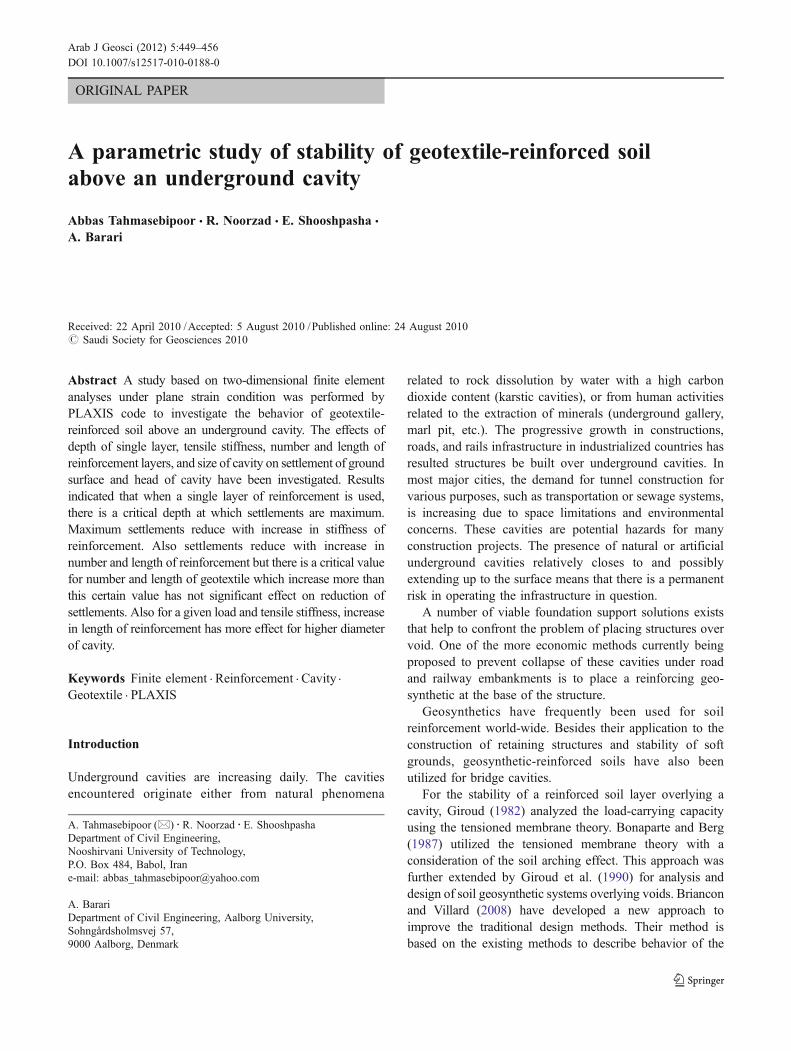
The geometry of the modeled problem is presented in Fig. 1.The soil was assumed to be homogenous and isotropic.
An elastic–plastic Mohr-coulomb failure criterion was usedto model the behavior of cohesionless overburden soil. Toprevent collapse of overburden soil into cavity, a concretelining was considered in the model. Plane strain conditionand 15-node triangular elements were used for analysis.Reinforcement layers were modeled using the geogridelement already implemented into the program. To model
the slip between the soil and reinforcement these elementsare combined with interfaces. Interfaces were placed onboth sides of the geotextile, allowing the geotextile to moveindependently of the surrounding soil. The interface frictionangles were given values equal to two thirds of the frictionangle of the soil. This allowed movement along theinterface, but no separation between the soil and geotextile.
Geotextiles are slender objects with a normal stiffnessbut with no bending stiffness. Reinforcement can onlysustain tensile forces and no compression.
When 15-node soil elements are employed the eachreinforcement element is defined by 5-nodes.
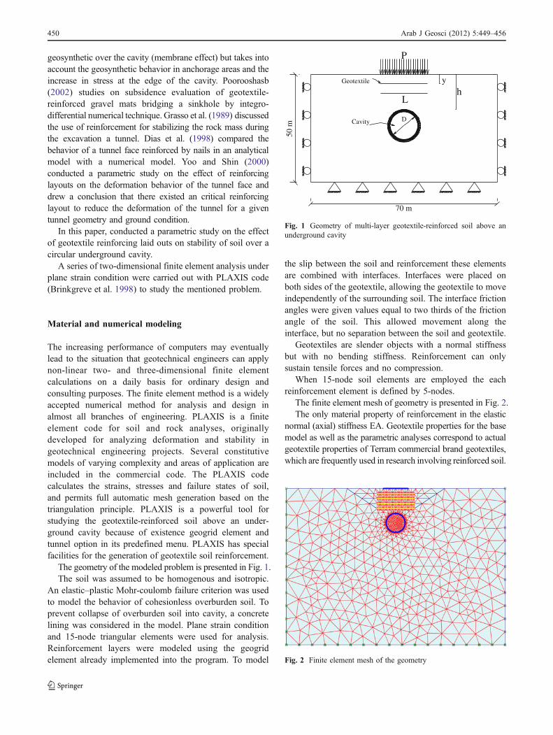
The finite element mesh of geometry is presented in Fig. 2.The only material property of reinforcement in the elastic
normal (axial) stiffness EA. Geotextile properties for the basemodel as well as the parametric analyses correspond to actualgeotextile properties of Terram commercial brand geotextiles,which are frequently used in research involving reinforced soil.
Geotextile
Cavity
P
yh
L
70 m
50 m
D
Fig. 1 Geometry of multi-layer geotextile-reinforced soil above anunderground cavity
Fig. 2 Finite element mesh of the geometry
450 Arab J Geosci (2012) 5:449–456
The soil parameters and concrete lining properties used inthe numerical analysis are listed in Tables 1 and 2,respectively, and correspond to cohesionless sand havingmedium stiffness. A small cohesion value was assigned tothe sand in order to prevent numerical complications. It shouldalso be mentioned that interface properties follow base soilproperties in both the lining and the geotextile, and are selectedby reducing the properties of the base soil by a factor of 0.85.
To minimize the boundary effect, the vertical boundary atthe far end, on the left- and right-hand side, is set 35 m awayfrom the center of the cavity and are assumed to be free invertical direction and restricted in the horizontal direction. Theselected value for the horizontal distance away from the cavitywas selected based on a sensitivity analysis in which theboundary was moved away from the cavity in consecutiveanalyses, monitoring the stresses and strains at and near theboundaries, until negligible values were encountered.
The bottom horizontal boundary is restricted in both thevertical and horizontal directions.
In the finite element modeling, the initial stress conditionof the unreinforced soil above a cavity was established firstby applying the gravity force due to soil and existence cavity.
A series of parametric finite element analyses wereperformed in order to investigate the effect of influencingparameters on the stability of the geotextile-reinforced soilabove an underground cavity. These parameters includedepth of single layer geotextile, tensile stiffness of geo-textile, number of reinforcement layers, and length ofgeotextile and diameter of cavity.
Effect of depth of single layer of geotextile
In order to investigate the effect of this parameter onmaximum settlement of ground surface and head of cavity,single layer of geotextile with tensile stiffness equal to500 KN/m and length of 12 m laid out in different depths.
The ratio of depth of geotextile layer(y) to thickness ofover burden of cavity (h), called “depth ratio”.
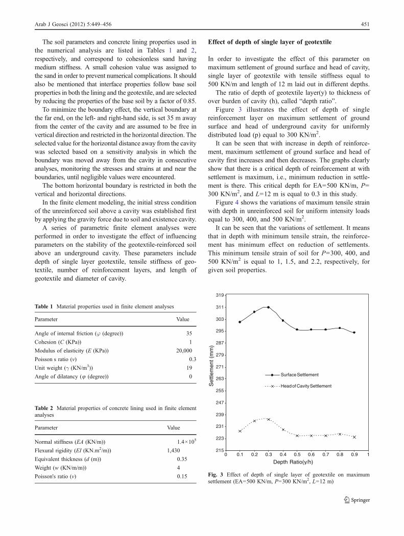
Figure 3 illustrates the effect of depth of singlereinforcement layer on maximum settlement of groundsurface and head of underground cavity for uniformlydistributed load (p) equal to 300 KN/m2.
It can be seen that with increase in depth of reinforce-ment, maximum settlement of ground surface and head ofcavity first increases and then decreases. The graphs clearlyshow that there is a critical depth of reinforcement at withsettlement is maximum, i.e., minimum reduction in settle-ment is there. This critical depth for EA=500 KN/m, P=300 KN/m2, and L=12 m is equal to 0.3 in this study.
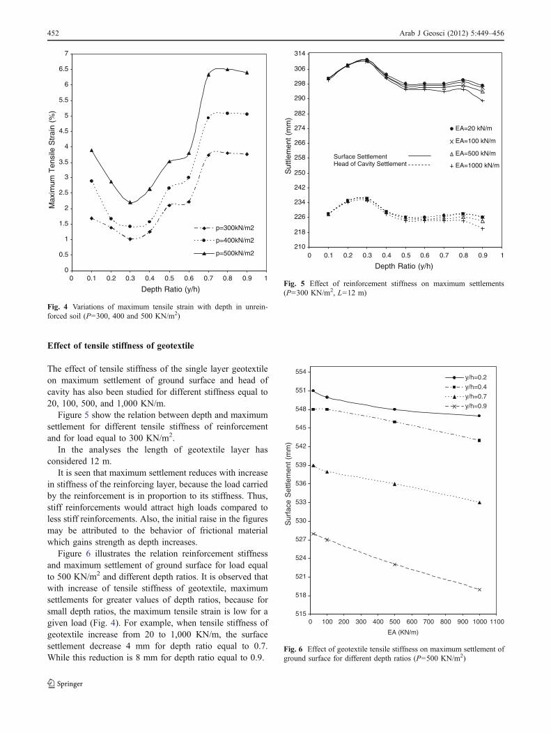
Figure 4 shows the variations of maximum tensile strainwith depth in unreinforced soil for uniform intensity loadsequal to 300, 400, and 500 KN/m2.
It can be seen that the variations of settlement. It meansthat in depth with minimum tensile strain, the reinforce-ment has minimum effect on reduction of settlements.This minimum tensile strain of soil for P=300, 400, and500 KN/m2 is equal to 1, 1.5, and 2.2, respectively, forgiven soil properties.
Table 1 Material properties used in finite element analyses
Parameter Value
Angle of internal friction (φ (degree)) 35
Cohesion (C (KPa)) 1
Modulus of elasticity (E (KPa)) 20,000
Poisson s ratio (v) 0.3
Unit weight (γ (KN/m3)) 19
Angle of dilatancy (8 (degree)) 0
Table 2 Material properties of concrete lining used in finite elementanalyses
Parameter Value
Normal stiffness (EA (KN/m)) 1.4×10⁵
Flexural rigidity (EI (KN.m2/m)) 1,430
Equivalent thickness (d (m)) 0.35
Weight (w (KN/m/m)) 4
Poisson's ratio (v) 0.15
215
223
231
239
247
255
263
271
279
287
295
303
311
319
0 0.1 0.2 0.3 0.4 0.5 0.6 0.7 0.8 0.9 1
Depth Ratio(y/h)
Set
tlem
ent (
mm
)
Surface Settlement
Head of Cavity Settlement
Fig. 3 Effect of depth of single layer of geotextile on maximumsettlement (EA=500 KN/m, P=300 KN/m2, L=12 m)
Arab J Geosci (2012) 5:449–456 451
Effect of tensile stiffness of geotextile
The effect of tensile stiffness of the single layer geotextileon maximum settlement of ground surface and head ofcavity has also been studied for different stiffness equal to20, 100, 500, and 1,000 KN/m.
Figure 5 show the relation between depth and maximumsettlement for different tensile stiffness of reinforcementand for load equal to 300 KN/m2.
In the analyses the length of geotextile layer hasconsidered 12 m.
It is seen that maximum settlement reduces with increasein stiffness of the reinforcing layer, because the load carriedby the reinforcement is in proportion to its stiffness. Thus,stiff reinforcements would attract high loads compared toless stiff reinforcements. Also, the initial raise in the figuresmay be attributed to the behavior of frictional materialwhich gains strength as depth increases.
Figure 6 illustrates the relation reinforcement stiffnessand maximum settlement of ground surface for load equalto 500 KN/m2 and different depth ratios. It is observed thatwith increase of tensile stiffness of geotextile, maximumsettlements for greater values of depth ratios, because forsmall depth ratios, the maximum tensile strain is low for agiven load (Fig. 4). For example, when tensile stiffness ofgeotextile increase from 20 to 1,000 KN/m, the surfacesettlement decrease 4 mm for depth ratio equal to 0.7.While this reduction is 8 mm for depth ratio equal to 0.9.
0
0.5
1
1.5
2
2.5
3
3.5
4
4.5
5
5.5
6
6.5
7
0 0.1 0.2 0.3 0.4 0.5 0.6 0.7 0.8 0.9 1
Depth Ratio (y/h)
Max
imum
Ten
sile
Str
ain
(%)
p=300kN/m2
p=400kN/m2
p=500kN/m2
Fig. 4 Variations of maximum tensile strain with depth in unrein-forced soil (P=300, 400 and 500 KN/m2)
210
218
226
234
242
250
258
266
274
282
290
298
306
314
0 0.1 0.2 0.3 0.4 0.5 0.6 0.7 0.8 0.9 1
Depth Ratio (y/h)
Sut
tlem
ent
(mm
)
EA=20 kN/m
EA=100 kN/m
EA=500 kN/m
EA=1000 kN/mSurface Settlement Head of Cavity Settlement
Fig. 5 Effect of reinforcement stiffness on maximum settlements(P=300 KN/m2, L=12 m)
515
518
521
524
527
530
533
536
539
542
545
548
551
554
0 100 200 300 400 500 600 700 800 900 1000 1100
EA (KN/m)
Sur
face
Set
tlem
ent (
mm
)
y/h=0.2
y/h=0.4
y/h=0.7
y/h=0.9
Fig. 6 Effect of geotextile tensile stiffness on maximum settlement ofground surface for different depth ratios (P=500 KN/m2)
452 Arab J Geosci (2012) 5:449–456
Thus when geotextile is laid out near the ground surface,the mobilized tension in reinforcement layer would decreaseand it would attract lower loads, hence increase in geotextiletensile stiffness has lower effect for smaller depth ratios.
Effect of number of reinforcement layers
For investigate the effect of number of reinforcement layeron maximum settlements and reduction of stresses, a seriesanalyses was carried out on model with different number ofgeotextile layers and for tensile stiffness equal to 50, 500,and 1,000 KN/m.
In the all analyses, the length of reinforcement layer wasconstant and equal to 12 m.
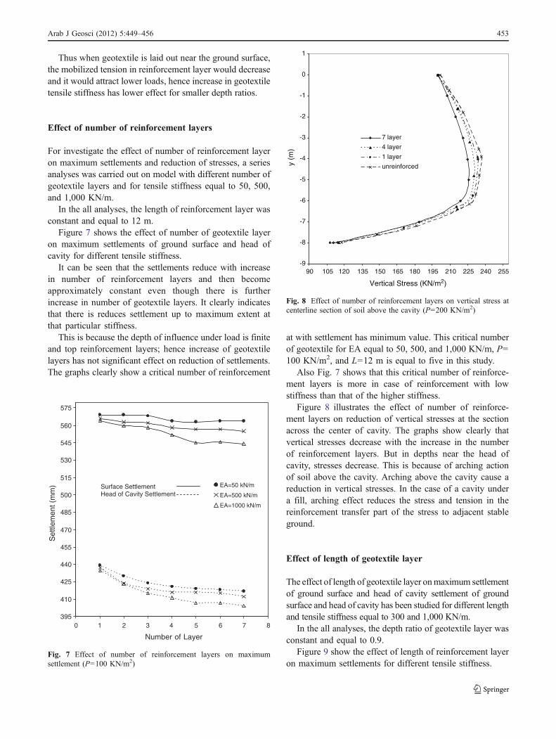
Figure 7 shows the effect of number of geotextile layeron maximum settlements of ground surface and head ofcavity for different tensile stiffness.
It can be seen that the settlements reduce with increasein number of reinforcement layers and then becomeapproximately constant even though there is furtherincrease in number of geotextile layers. It clearly indicatesthat there is reduces settlement up to maximum extent atthat particular stiffness.
This is because the depth of influence under load is finiteand top reinforcement layers; hence increase of geotextilelayers has not significant effect on reduction of settlements.The graphs clearly show a critical number of reinforcement
at with settlement has minimum value. This critical numberof geotextile for EA equal to 50, 500, and 1,000 KN/m, P=100 KN/m2, and L=12 m is equal to five in this study.
Also Fig. 7 shows that this critical number of reinforce-ment layers is more in case of reinforcement with lowstiffness than that of the higher stiffness.
Figure 8 illustrates the effect of number of reinforce-ment layers on reduction of vertical stresses at the sectionacross the center of cavity. The graphs show clearly thatvertical stresses decrease with the increase in the numberof reinforcement layers. But in depths near the head ofcavity, stresses decrease. This is because of arching actionof soil above the cavity. Arching above the cavity cause areduction in vertical stresses. In the case of a cavity undera fill, arching effect reduces the stress and tension in thereinforcement transfer part of the stress to adjacent stableground.
Effect of length of geotextile layer
The effect of length of geotextile layer onmaximum settlementof ground surface and head of cavity settlement of groundsurface and head of cavity has been studied for different lengthand tensile stiffness equal to 300 and 1,000 KN/m.
In the all analyses, the depth ratio of geotextile layer wasconstant and equal to 0.9.
Figure 9 show the effect of length of reinforcement layeron maximum settlements for different tensile stiffness.
395
410
425
440
455
470
485
500
515
530
545
560
575
0 1 2 3 4 5 6 7 8
Number of Layer
Set
tlem
ent (
mm
) EA=50 kN/m
EA=500 kN/m
EA=1000 kN/m
Surface Settlement Head of Cavity Settlement
Fig. 7 Effect of number of reinforcement layers on maximumsettlement (P=100 KN/m2)
-9
-8
-7
-6
-5
-4
-3
-2
-1
0
1
90 105 120 135 150 165 180 195 210 225 240 255
Vertical Stress (KN/m2)y
(m)
7 layer
4 layer
1 layer
unreinforced
Fig. 8 Effect of number of reinforcement layers on vertical stress atcenterline section of soil above the cavity (P=200 KN/m2)
Arab J Geosci (2012) 5:449–456 453
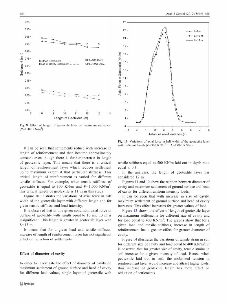
It can be seen that settlements reduce with increase inlength of reinforcement and then become approximatelyconstant even though there is further increase in lengthof geotextile layer. This means that there is a criticallength of reinforcement layer which reduces settlementup to maximum extent at that particular stiffness. Thiscritical length of reinforcement is varied for differenttensile stiffness. For example, when tensile stiffness ofgeotextile is equal to 300 KN/m and P=1,000 KN/m2,this critical length of geotextile is 11 m in this study.
Figure 10 illustrates the variations of axial force in halfwidth of the geotextile layer with different length and forgiven tensile stiffness and load intensity.
It is observed that in this given condition, axial force inportion of geotextile with length equal to 10 and 13 m isinsignificant. This length is greater in geotextile layer withL=13 m.
It means that for a given load and tensile stiffness,increase of length of reinforcement layer has not significanteffect on reduction of settlements.
Effect of diameter of cavity
In order to investigate the effect of diameter of cavity onmaximum settlement of ground surface and head of cavityfor different load values, single layer of geotextile with
tensile stiffness equal to 500 KN/m laid out in depth ratioequal to 0.3.
In the analyses, the length of geotextile layer hasconsidered 12 m.
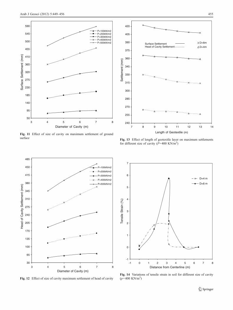
Figures 11 and 12 show the relation between diameter ofcavity and maximum settlement of ground surface and headof cavity for different uniform intensity loads.
It can be seen that with increase in size of cavity,maximum settlement of ground surface and head of cavityincreases. This effect increases for greater values of load.
Figure 13 shows the effect of length of geotextile layeron maximum settlements for different size of cavity andfor load equal to 400 KN/m2. The graphs show that for agiven load and tensile stiffness, increase in length ofreinforcement has a greater effect for greater diameter ofcavity.
Figure 14 illustrates the variations of tensile strain in soilfor different size of cavity and load equal to 400 KN/m2. Itis observed that for greater size of cavity, tensile strains insoil increase for a given intensity of load. Hence, whengeotextile laid out in soil, the mobilized tension inreinforcement layer would increase and attract higher loads,thus increase of geotextile length has more effect onreduction of settlements.
-1
1
3
5
7
9
11
13
15
17
19
21
23
25
-1 0 1 2
Axi
al F
orce
in G
eote
xtile
(kN
/m)
Distance From Centerline (m)
L=8 m
L=10 m
L=13 m
3 4 5 6 7 8
Fig. 10 Variations of axial force in half width of the geotextile layerwith different length (P=300 KN/m2, EA=1,000 KN/m)
205
215
225
235
245
255
265
275
285
295
305
315
325
7 8 9 10 11 12 13 14
Length of Geotextile (m)
Set
tlem
ent (
mm
)
EA=300 kN/m
EA=1000 kN/mSurface Settlement Head of Cavity Settlement
Fig. 9 Effect of length of geotextile layer on maximum settlement(P=1000 KN/m2)
454 Arab J Geosci (2012) 5:449–456
240
255
270
285
300
315
330
345
360
375
390
405
420
7 8 9 10 11 12 13 14
Length of Geotextile (m)
Set
tlem
ent (
mm
)
D=6m
D=4mSurface Settlement Head of Cavity Settlement
Fig. 13 Effect of length of geotextile layer on maximum settlementsfor different size of cavity (P=400 KN/m2)
30
65
100
135
170
205
240
275
310
345
380
415
450
485
3 5 6 7 8
Diameter of Cavity (m)
Hea
d of
Cav
ity S
ettle
men
t (m
m)
P=100kN/m2
P=200kN/m2
P=300kN/m2
P=400kN/m2
P=500kN/m2
4
Fig. 12 Effect of size of cavity maximum settlement of head of cavity
50
95
140
185
230
275
320
365
410
455
500
545
590
3 4 5 6 7 8
Sur
face
Set
tlem
ent
(mm
)
Diameter of Cavity (m)
P=100kN/m2P=200kN/m2P=300kN/m2P=400kN/m2P=500kN/m2
Fig. 11 Effect of size of cavity on maximum settlement of groundsurface
-1
0
1
2
3
4
5
6
7
-1 0 1 2 3 4 5 6 7 8
Ten
sile
Str
ain
(%)
Distance from Centerline (m)
D=4 m
D=6 m
Fig. 14 Variations of tensile strain in soil for different size of cavity(p=400 KN/m2)
Arab J Geosci (2012) 5:449–456 455

Conclusions
From the above discussion the following conclusions canbe drawn:
1. In case of single layer of reinforcement above a cavity,there is a critical depth of reinforcement at whichminimum reduction in settlement is achieved. Thiscritical depth for EA=500 KN/m, P=300 KN/m2, andL=12 m is equal to 0.3 in this study.
2. The effect of increase in stiffness of the reinforcementhas been found to reduce the maximum settlements ofground surface and creases for greater values of depthratios.
3. The maximum settlements of ground surface and headof cavity have been found to reduce with increase innumber of reinforcement layers. But there are a criticalnumber of geotextile layers which increase more thanthis certain value is not effective in settlement reduc-tion. This critical number of geotextile for EA equal to50, 500, and 1,000 KN/m, P=100 KN/m2 and L=12 mis equal to five in this study. This critical value isgreater in case of reinforcement with low stiffness.
Also vertical stresses decrease with the increase innumber of layers.
4. The maximum settlements reduce with increase inlength of reinforcement. But there is a critical lengthwhich increases more than this certain value has notsignificant effect on reduction of settlements. Thiscritical length of geotextile for EA equal to 300 KN/mand P=1,000 KN/m2 is 11 m in this study.
5. With increase in size of cavity, maximum settlement ofground surface and head of cavity increases. Also for agiven load and tensile stiffness, increase in length of rein-forcement has more effect for greater diameter of cavity.
References
Bonaparte R, Berg RR (1987) The use of geosynthetics to supportroadways over sinkhole prone areas. In: Proceedings of the 2ndMultidisciplinary Conference on Sinkholes and the Environmen-tal Impacts of Karst, Orlando, FL. pp. 437–445
Briancon L, Villard P (2008) Design of geosynthetic reinforcedplatforms spanning localized sinkholes. J Geotextile Geomem-branes 26(5):416–428
Brinkgreve RBJ et al (1998) Plaxis finite element code for soil androck analyses. Delft University of Technology, The Netherlands
Dias D, Kastner R, Subrin D, Wong H, Dubois R (1998) Behaviour ofa tunnel face reinforced by bolts: comparison between analytical-numerical models. In: Proceeding Of the Geotechnics of HardSoils—Soft Rocks, Balkema. pp. 961–972
Giroud JP (1982) Design of geotextile associated with geomembranes.In: Proceedings of the 2nd International Conference on Geo-textiles, Las Vegas, NV, pp. 37–42
Giroud JP, Bonaparte R, Beech JF, Gross BA (1990) Design of soillayer- geosynthetic systems overlying voids. J Geotextile Geo-membranes 9(1):11–50
Grasso P, Mahtab A, Pelizza S (1989) Reinforcing a rock zone forstabilizing a tunnel in complex formations. Int Congr Prog InnovTunn Tor 2:663–670
Poorooshasb HB (2002) Subsidence evaluation of geotextile reinforcedgravel mats bridging a sinkhole. J Geosynthetics Int 9(3):259–282
Yoo CS, Shin HK (2000) Behavior of tunnel face pre-reinforced withsub-horizontal pipes. In: Proceeding Of Geotechnical Aspect ofUnderground Construction in Soft Ground, Balkema. pp 441–446
456 Arab J Geosci (2012) 5:449–456