a numerical exploration of parameter dependence in power
TRANSCRIPT

A Numerical Exploration of Parameter Dependence in
Power Optimal Flapping Flight
David J. Willis∗ Jaime Peraire † Mark Drela †Jacob K. White‡
Massachusetts Institute Of Technology, 77 Massachusetts Ave., Cambridge, MA 02139, USA.
A computational framework for analyzing and designing efficient flapping flight vehiclesis presented. Two computational tools are considered: a Betz Criterion code proposed byHall et. al., and an accelerated, unsteady, potential flow solver. The parameters consideredin this paper are: the flapping frequency, the flapping amplitude in both up-down andforward-aft directions, and the addition of a mid-wing hinge for articulated flapping flight.The flapping kinematics are represented using harmonics.
Three numerical experiments are examined for the flapping flight analysis. The firstexperiment involves sweeping through a basic flapping flight parametric design space. Thesecond experiment minimizes flight power at a given flight condition using a quasi-Newtonoptimization. The third experiment demonstrates the conversion of the problem from awake only analysis to a 3-D flapping wing geometry.
Nomenclature
Φ up-down flapping angleΨ fore-aft (sweep) angleφ phase lag in Φψ phase lag in Ψb spanc chords arc length along wingsj arc length position of jointt timeXY Z Cartesian location in spaceuvw Cartesian velocity componentsU wing center-point velocity (in −X direction)V total local velocityω primary flapping frequencys̄j fractional joint position (= 2sj/b)µ advance ratio (= U/(ωb)Γ wing circulationc` section lift coefficient (= 2Γ/cV )cd section drag coefficientcd0 constant coefficient of profile-drag polar
∗Graduate Student, Department of Aeronautics and Astronautics, 77 Massachusetts Ave., Cambridge, MA 02139.†Professor, Department of Aeronautics and Astronautics, 77 Massachusetts Ave., Cambridge, MA 02139.‡Professor, Department of Electrical Engineering and Computer Science, 77 Massachusetts Ave., Cambridge, MA 02139.
1 of 31
American Institute of Aeronautics and Astronautics

cd2 quadratic coefficient of profile-drag polarc`0 minimum-drag c` of profile-drag polarρ fluid densityL overall lift in Y directionT overall thrust in −X directionP overall powerCL overall lift coefficient (= 2L/ρU2b2)CT overall thrust coefficient (= 2T/ρU2b2)CP overall power coefficient (= 2P/ρU3b2)
I. Introduction
This paper investigates flapping flight using several low fidelity, highly efficient, computational tools.From an engineering perspective, understanding wing kinematic parametric dependence can guide design ofmore effective flight vehicles. From a biological perspective, understanding the importance of parametricdependencies can provide insight into natural flight kinematics as well as the evolutionary process resultingin flight. There have been several presentations of flapping flight parameters.1,2, 4, 5, 8, 13 This paper makesuse of computational approaches which are well suited to understand the basic parameter dependencies whileutilizing moderate computational resources.
Due to the complexity of flapping flight kinematics, Euler and Navier Stokes solvers6,7 are not consideredpractical for parameter dependence investigations, and lower fidelity tools are therefore used here. Extensiveuse will be made of the large flapping amplitude wake-only-Betz criterion methods presented by Hall etal.9–11 The Hall et. al. approach considers a prescribed wake shape, defined by a specified harmonic motionof the generating lifting line. A set of force constraints are then applied to determine the minimum-powervorticity distribution on this wake. A vortex-lattice method is used to relate the wake’s velocity field tothe vorticity distribution. In the extended method in Hall et al.,11 a viscous profile drag and stall modelare included in the optimization. In this work a more general wake geometry description is used, with amid-span joint and higher-harmonic motion being allowed. As in Hall,11 a simple quadratic-polar profiledrag model is included.
In this paper we also demonstrate the use of an accelerated, unsteady potential flow panel method12
for analyzing the wakes which result from the Hall et al. approach. This panel method has features whichare particularly effective in flapping flight analysis: a rapid solution of a morphing body problem due tothe advanced acceleration algorithms,21,22,28 an automatic wake generation procedure using vortex particlewakes,23–25 and the ability to model both thin-membrane and thick body representations of the geometry.
The flight parameters of interest in the current investigation are motivated by observations of bird flight:the wing flapping frequency,4,11 flapping amplitude,11,15 forward-aft wing motion,13,18 a second flappingharmonic,13,18 and a mid-wing joint (articulated flapping).
In order to demonstrate the versatility of the computational framework, three experiments are considered.The first experiment involves sweeping through the basic flapping flight parametric design space. The secondexperiment demonstrates a quasi-Newton optimization to minimize flight power. The third experimentdemonstrates the conversion of the problem from a wake only Betz analysis to a 3-D flapping wing geometry.
II. The Geometric and Kinematic Parameters of Interest
The following parameters of symmetric flapping flight are considered in the present investigation.
1. Flapping Frequency (or advance ratio of Strouhal number): Several researchers have examinedflapping frequency in both experimental settings,5,15 and in computational settings.4,11,14 Hall et. al.
2 of 31
American Institute of Aeronautics and Astronautics

presented results in their original work showing the effect of flapping frequency on simple harmonichinged flapping wings.
2. Flapping Amplitudes: For simple hinged flapping Hall et al.8 computed the dependencies of flappingamplitude. Flapping amplitude has been examined experimentally and presented for both birds13 andbats.13,15
3. Flapping with a Second Harmonic: Birds and bats demonstrate a non-unity upstroke to down-stroke ratio,18 which is represented here using a second flapping harmonic. There is typically a bias tospending more time during the downstroke portion of flapping than the upstroke.13,18
4. Forward-Aft Flapping Kinematics: The path traveled by the wingtip is rarely a simple up-downpath.13,18 The downstroke typically involves downward-and-forward motions, while the upstroke willin most cases involve upward-and-rearward motions.
5. Multiply Hinged Wings: In nature the existence of articulated wings is prevalent. Observing birdflight, the wing is fully extended during the downstroke and will fold during the upstroke. The degreeof folding during the upstroke can be significant in certain flight regimes.13 Similarly, bats will undergoa nearly fully extended wing downstroke, with a wing-folding of some proportion during the upstroke.13
Natural flapping flight is often used as a model for flapping flight; however, it is unclear whether thefeatures of natural flapping flight have evolved primarily to minimize flight power, or whether other survivalconsiderations such as maneuverability or skeletal or muscular limitations have also played a significant role.Understanding these trade offs is a primary goal of the present work.
A. The Wing Geometry Kinematics
The wake geometry is defined as the trace of a two-segment lifting line representing the wing, illustrated infigure 1.
The segment orientations are defined by the flap angles Φi and Φo, and the two sweep angles Ψi and Ψo.The time variation of these angles is assumed to be the sum of two harmonics of frequency ω and 2ω, withvarious appropriate phase angles φ and ψ included.
Φi(t) = Φi,0 + Φi,1 cos(ωt)+ Φi,2 cos(2ωt+ φi,21) (1)
Φo(t) = Φo,0 + Φo,1 cos(ωt+ φo,i)+ Φo,2 cos(2ωt+ φo,i + φo,21) (2)
Ψi(t) = Ψi,0 + Ψi,1 cos(ωt+ ψφ)+ Ψi,2 cos(2ωt+ ψφ + ψi,21) (3)
Ψo(t) = Ψo,0 + Ψo,1 cos(ωt+ ψφ + ψo,i)+ Ψo,2 cos(2ωt+ ψφ + ψo,i + ψo,21) (4)
The position of a point (X,Y, Z) on the lifting line, at arc length position s and time t, is then given asfollows.
X(s, t) =
{−Ut + s cos Φi(t) sinΨi(t) , 0 ≤ s ≤ sj
−Ut + sj cos Φi(t) sinΨi(t) + (s− sj) cos Φo(t) sinΨo(t) , sj ≤ s ≤ b/2(5)
3 of 31
American Institute of Aeronautics and Astronautics
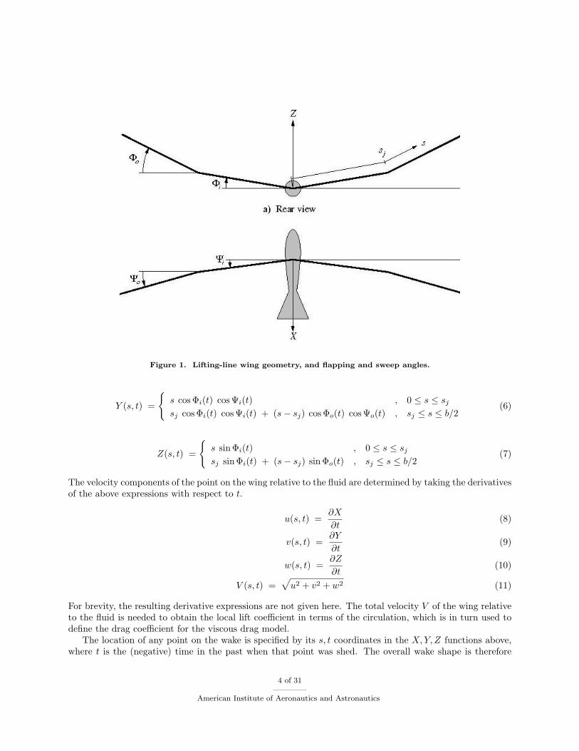
Figure 1. Lifting-line wing geometry, and flapping and sweep angles.
Y (s, t) =
{s cos Φi(t) cos Ψi(t) , 0 ≤ s ≤ sj
sj cos Φi(t) cos Ψi(t) + (s− sj) cos Φo(t) cos Ψo(t) , sj ≤ s ≤ b/2(6)
Z(s, t) =
{s sinΦi(t) , 0 ≤ s ≤ sj
sj sinΦi(t) + (s− sj) sinΦo(t) , sj ≤ s ≤ b/2(7)
The velocity components of the point on the wing relative to the fluid are determined by taking the derivativesof the above expressions with respect to t.
u(s, t) =∂X
∂t(8)
v(s, t) =∂Y
∂t(9)
w(s, t) =∂Z
∂t(10)
V (s, t) =√u2 + v2 + w2 (11)
For brevity, the resulting derivative expressions are not given here. The total velocity V of the wing relativeto the fluid is needed to obtain the local lift coefficient in terms of the circulation, which is in turn used todefine the drag coefficient for the viscous drag model.
The location of any point on the wake is specified by its s, t coordinates in the X,Y, Z functions above,where t is the (negative) time in the past when that point was shed. The overall wake shape is therefore
4 of 31
American Institute of Aeronautics and Astronautics
specified by the following 19 parameters.
{Φi,0 Φi,1 Φi,2 Φo,0 Φo,1 Φo,2 (12)Ψi,0 Ψi,1 Ψi,2 Ψo,0 Ψo,1 Ψo,2 (13)φi,21 φo,i ψφ ψi,21 ψo,i (14)s̄j µ } (15)
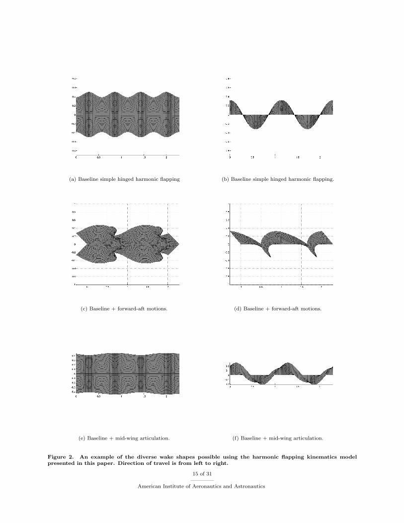
Figure 2 shows several wake traces generated for a selection of these parameters. This illustrates the widevariety of flapping motions and corresponding wake shapes which can be defined by this parameterization.
III. A Brief Description of the Simulation Tools
The two approaches which are used in this work are discussed briefly in this section. The details pertainingto the implementation and theory of each of the methods can be found in the respective references.9–12
A. The Hall et al Method
The Hall et. al. approach9–11 was implemented in a form similar to that presented in the references. The Hallet al. method determines the circulation distribution on prescribed periodic wake shape which minimizes thetotal time-average power required to achieve specified average forces. The total power includes the viscouspower, which is computed using a quadratic profile drag polar using the lift coefficient determined from theinstantaneous circulation.
c` =2ΓcV
(16)
cd(c`) = cd0 + cd2(c` − c`0)2 (17)
By augmenting the system using Lagrange multipliers, the total power can be minimized with respect to aset of prescribed inviscid resultant forces. The solution process is described as follows:
1. Prescribe a vortex-lattice wake geometry representation based on the trace of the wing trailing edge.The wing trailing edge trace is determined using the flapping parameters outlined earlier.
2. Prescribe the force constraints for the particular geometry.
3. Prescribe the viscous model parameters (c, c`0 , cd0 , cd2).
4. Solve for the circulation and corresponding vorticity distribution which minimizes the power.
The approach of Hall et al. requires only that the wake trace be specified, and hence is a fairly powerful toolfor flapping parameter exploration. However, since the flapping wing geometry is only minimally accountedfor, it is unclear how effectively the optimum vorticity distribution can be generated by a realizable wing.Given a wing with infinite actuation possibilities, clearly the generation of the optimum wake vorticitydistribution is an easy task, however, in most practical situations geometric constraints are present whichprevent the production of an optimal wake. As a result, the authors have performed some preliminarycoupling of the Hall wake only method with an unsteady potential flow solver to investigate the winggeometry necessary to generate the power optimal wake vorticity distribution.
B. The Panel Method Simulation Methodology
The unsteady panel method used in this work is FastAero.12 The FastAero approach has the followingfeatures which are particularly advantageous to flapping flight analysis:
5 of 31
American Institute of Aeronautics and Astronautics

1. Vortex Particle Representation of the wake: The unsteady motion of the wake is represented using avortex particle method.23–26 Since the vortex particles advect freely with the local velocity, and do notrequire connectivity data in their representation, they are particularly well suited for the automaticwake generation problem.
2. Accelerated solution methods: The use of a precorrected-FFT28 matrix vector product acceleratedGMRES27 iterative solution technique, the scalar potential flow problem is rapidly solved. In addition,a Fast Multipole Tree21,22 acceleration routine is used to accelerate the vortex particle component ofthe solution method. The combined p-FFT-FMT approach provides the necessary acceleration allowingmorphing body problems to be computed rapidly and accurately.
3. Membrane and thick body formulations: FastAero has several boundary integral formulations imple-mented in the solution framework. Therefore, it is possible to represent the wing as an infinitely-thinprescribed geometry wing, or as a wing with a prescribed thickness profile. The advantage of a thinbody representation is that the grid generation for morphing bodies is significantly easier than thethick body mesh generation problem. The thick body formulation is useful for detailed analysis offlapping flight when the airfoil profile is relevant.
Although FastAero has several advantages for flapping flight analysis, the method does not include a viscouscorrection. Viscous effects can be approximated using the section local velocity, the section bound circulation,and a drag polar for the airfoil under consideration at the Reynolds number desired; however, future plansinclude the incorporation of a viscous model into the solution framework.
IV. Numerical Experiments
Several numerical experiments are considered in this paper demonstrating the versatility of the compu-tational framework which has been implemented.
A. Numerical Experiment 1
The first numerical experiment considers a parametric design space sweep using an implementation of theHall et. al. approach. Due to the rapid computation of the minimum power wake vorticity distribution,design space sweeps with a small number of parameters are possible. However, limitations on the numberof parameters are strict due to the exponential increase in computational complexity. Practical moderatefidelity design space sweeps are limited to computations with 4-5 variables. The following pseudo codeillustrates the parameter sweep process:
for(i_omega = 2.0 : i_omega < 12 : i_omega++){for(i_amplitude = 5: i_amplitude < 65 : i_amplitude = i_amplitude+5)% Flapping angle here is in degrees{for(i_param1 = min_param1: i_param1 < max_param1 : i_param1 = i_param1 + delta_param1){for(i_param2 = min_param2: i_param2 < max_param2 : i_param2 = i_param2 + delta_param2){Mesh the wake geometry: Mesh(i_omega, i_amplitude, i_param1, i_param2)Solve for the current minimum power vorticityStore the coefficient of power and parameters
}}
}
6 of 31
American Institute of Aeronautics and Astronautics
}
Results of the design space sweeps are presented based on the minimum power for a given pair of advanceratio and inner-first harmonic up-down flapping angle values. This is considered in order to compare theresulting minimum power coefficient to a simple flapping wing baseline model consisting only of first harmonicup-down flapping motions and a variable advance ratio. Although minimum power flight is desirable, equallyimportant is the sensitivity of that minimum power flight to off-design operation.
1. Flapping Frequency and Amplitude
In the original work by Hall et. al., they investigate the effect of flapping frequency and amplitude. Forcomparison, we perform a similar investigation using the following parameter values:
µ−1 = 2, 3 . . . 10.Φo,0 = Φi,0 = Φo,2 = Φi,2 = 0Φo,1 = Φi,1 = π
36 , 2π36 . . . 13 π
36 .
Figure 3 illustrates the power coefficient variation with the flapping advance ratio and the flapping am-plitude for several different flight conditions.
DiscussionThe simple hinged flapper demonstrates several features of efficient flapping flight. As noted by Hall et al.11
there is a low sensitivity of minimum power flight to advance ratio across a large interval of practical values.This low sensitivity is due to the ability to tune the flapping amplitude at a given non-optimal advance ratiosuch that the overall power is minimized. This tuning of the flapping amplitude enables efficient and effectiveoperation across a wide range of velocities, flapping frequencies and flapping amplitudes. Furthermore, thelow sensitivity of the power coefficient to sub-optimal parameter choices in both flapping amplitude andadvance ratio provides low off design flight power consumption.
In the sections which follow, comparisons of this baseline hinged flapping flight model are made forsituations in which additional flapping degrees of freedom are introduced.
2. Forward-Aft Wing Stroke Behavior
In this example the fore-aft wing flapping are considered, in addition to the up-down motion. The phasebetween the up-down and fore-aft motion is also considered. The design space sweeps are performed over:
µ−1 = 2, 3 . . . 10Φo,0 = Φi,0 = Φo,2 = Φi,2 = 0Φo,1 = Φi,1 = π
36 , 2π36 . . . 13 π
36Ψo,0 = Ψi,0 = Ψo,2 = Ψi,2 = 0Ψo,1 = Ψi,1 = π
36 , 2π36 . . . 6
π36
ψo,21 = ψi,21 = π8 ,
π4 . . . 2π
The results are shown in figure 4. The wake shape corresponding to the minimum power solution in thedesign space sweep is illustrated in figures 5-6.
DiscussionThe design space sweep over an interval of forward-aft flapping angles demonstrates the following:
1. The additional degree of freedom associated with the forward-aft motion results in lower power con-sumption. However, it should be noted that the gains are small for low thrust situations and may notoffset the cost associated with prescribing the motion.
7 of 31
American Institute of Aeronautics and Astronautics
2. The forward-aft motion which minimizes power matches well with the observed behavior in naturalflapping flight. Although it is natural for wing-flapping animals to have their wings advance during thedownstroke (due to the production of thrust over the wings), it may also serve to reduce their powerconsumption.
3. At higher thrust to lift ratios, the forward-aft flapping motion becomes more effective in reducingpower consumption. The coupled forward-aft, up-down motion of the wings results in a wake whosedownstroke trace covers a large area and lies in a plane which is close to perpendicular to the desiredresultant force. The forward-aft motion of the wings can therefore make the downstroke more closelyresemble a tilted actuator disk. Based on these results, increased forward aft motion of the wings istherefore expected in steep climbing flight, slow flight, and during takeoff. The resultant of the lift andthrust effectively act together to produce motion in these flight regimes.
4. The motion which results in optimal minimum power flight implies forward-downward motion of thewing during the downstroke and upward-rearward motion during the upstroke. The correspondingwake shapes are illustrated in figures 5-6.
5. As the advance ratio tends toward zero, the amplitude of the forward-aft motions are reduced to achieveminimum power consumption. This effect is likely seen in the computations in order to reduce viscouspower loss at higher reduced frequencies. In addition, as the up-down flapping amplitude increases,the forward-aft wing motions are attenuated. Again, this is likely a result of curbing the viscous powerloss associated with more rapid relative motions.
3. The Second Harmonic
In this numerical experiment the addition of a second harmonic to the wing kinematics is examined. In thissimulation the design space sweep is performed over:
µ−1 = 2, 3 . . . 10Φo,0 = Φi,0 = 0Φo,1 = Φi,1 = π
36 , 2π36 . . . 13 π
36Φo,2 = Φi,2 = π
36 , 2π36 . . . 13 π
36φo,21 = φi,21 = π
8 ,π4 . . . 2π
Figures 7 – 8 illustrate the second harmonic design space search. Figures 9-10 illustrate the wake shapescorresponding to the minimum power coefficient determined during the design space sweep.
DiscussionThe results of the design space sweep appear to demonstrate a greater positive effect on power reductionthan is actually observed. This is due to the method chosen for representing the results. When the flappingamplitude of the first harmonic is low, the second harmonic assumes the role of the dominant flapping am-plitude. Therefore, the apparent reduction in power which is illustrated in the figures is not as significant asit appears. This is a pronounced effect in the figures7 and 8 when Φo,1 < 0.3 radians.
The minimum power required for flapping when considering both the first and second harmonics is lessthan the minimum power of the baseline result. Considering two harmonics enables the downstroke wake toadopt a more effective shape in for producing the flight forces.
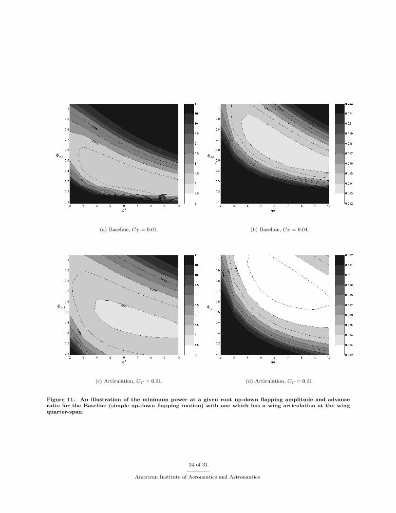
4. Articulation Result Behavior
The final parameter which is considered in the design space sweep experiment is the mid-wing joint (orarticulation) of the wing. In this simulation the design space sweep is performed over:
8 of 31
American Institute of Aeronautics and Astronautics

µ−1 = 2, 3 . . . 10.Φo,0 = Φi,0 = Φo,2 = Φi,2 = 0Φi,1 = π
36 , 2π36 . . . 13 π
36Φo,1 = π
36 , 2π36 . . . 13 π
36φi,o = π
8 , 2π8 . . . 2π
The results of the Articulation design space sweep are illustrated in figures 11 – 12. Figures 13-14 illus-trate the wake shapes corresponding to the minimum power coefficient determined during the design spacesweep for articulated flapping flight.
DiscussionConsidering the results in figure 11, articulated flapping flight tends to reduce the minimum power whilealso enlarging the region of minimum power. As a result the minimum power solution is less sensitive to theflapping parameters than the baseline model. Comparing figures 11 and 12 to the baseline example demon-strates the advantage of articulation when the flapping amplitude increases and the advance ratio decreases.This suggests that the viscous power loss is minimized in the articulated flapping flight simulations. In fact,in the current model articulation results in lower relative velocities at the wing tips therefore minimizing theviscous power loss. This viscous power savings effect is more pronounced when large flapping amplitudes areconsidered.
In nature many birds fold their wings to a certain extent during the upstroke of the wingbeat. Onesignificant reason for an articulated upstroke is the ease in which the outer region of the wing can beunloaded during the upstroke. If birds did not have an articulated wing, significant twist would be requiredto have a lightly loaded wingtip region during the upstroke motion. The Hall et al. model does not constrainthe wing twist required to create the optimal vorticity distribution. Therefore, it is likely that articulationserves the dual purpose of providing a functional morphology resulting in a lightly loaded upstroke motionwhile also providing a means for overall flight power reduction.
B. Numerical Experiment 2: Optimization of the Flight Power
In the second numerical experiment, a more rigorous approach for minimizing flapping flight power is consid-ered. The flight power coefficient is minimized for specified flight conditions over a restricted set of flappingparameters using a BFGS19 quasi-Newton method.20 A 3 × 2 array of flight parameters is examined forthe flapping problem. Three different values of cd0 = cd2 = 0.01, 0.03, 0.10 are considered for two separateapproximate climb angles (γapprox = 10o, 30o). The goal of this experiment was to determine the optimalset of parameters for a given set of flight conditions.
1. Setting up the Quasi-Newton Method
The following pseudo code demonstrates the quasi-Newton approach taken in this experiment:
for(i_condition = 0: Number_Of_Flight_Conditions){Initialize the case: Set the CL, CT, CD_0 and CD_2Setup the parameters over which optimization is to take placeSetup the initial guess for the parametersStart the BFGS routine to find the optimal parameter values
for the current flight condition}
The gradients used in the BFGS optimization are computed using a finite difference approach, hence, asthe number of parameters increases, the cost associated with the gradient evaluations increases. In futureimplementations an adjoint based approach for sensitivity computations will be considered.
9 of 31
American Institute of Aeronautics and Astronautics
2. A Note Regarding Solution Optimality
It should be noted that the results presented in this section represent local minimums. Although an effortwas made to explore different initial conditions in the design space, the power dependence on flappingparameters in flapping flight has many local minimums. As such, we present the optimal results for thesearch for minimum power. In addition, the design space over which the optimization is taking placepresents a challenge to gradient based approaches due to the low sensitivity of the minimum power to theflapping frequency in large regions of the space.
In this experiment, the design space under consideration has six free parameters over which the opti-mization process is carried out.
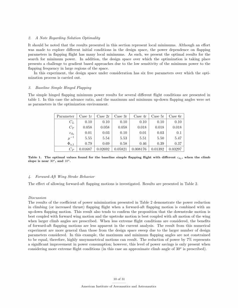
3. Baseline Simple Hinged Flapping
The simple hinged flapping minimum power results for several different flight conditions are presented intable 1. In this case the advance ratio, and the maximum and minimum up-down flapping angles were setas parameters in the optimization environment.
Parameter Case 1r Case 2r Case 3r Case 4r Case 5r Case 6rCL 0.10 0.10 0.10 0.10 0.10 0.10CT 0.058 0.058 0.058 0.018 0.018 0.018cd0 0.01 0.03 0.10 0.01 0.03 0.1µ−1 5.55 5.54 5.53 5.51 5.50 5.47Φo,1 0.79 0.69 0.58 0.46 0.39 0.37CP 0.01687 0.02692 0.05821 0.008176 0.01392 0.03297
Table 1. The optimal values found for the baseline simple flapping flight with different cd0 , when the climbslope is near 30o, and 10o.
4. Forward-Aft Wing Stroke Behavior
The effect of allowing forward-aft flapping motions is investigated. Results are presented in Table 2.
DiscussionThe results of the coefficient of power minimization presented in Table 2 demonstrate the power reductionin climbing (or increased thrust) flapping flight when a forward-aft flapping motion is combined with anup-down flapping motion. This result also tends to confirm the proposition that the downstroke motion isbest coupled with forward wing motion and the upstroke motion is best coupled with aft motion of the wingwhen larger climb angles are prescribed. When less extreme flight conditions are considered, the benefitsof forward-aft flapping motions are less apparent in the current analysis. The result from this numericalexperiment are more general than those from the design space sweep due to the larger number of designparameters considered. In this example, the maximum and minimum flapping angles are not constrainedto be equal, therefore, highly unsymmetrical motions can result. The reduction of power by 7% representsa significant improvement in power consumption; however, this level of power savings is only present whenconsidering more extreme flight conditions (in this case an approximate climb angle of 30o is prescribed).
10 of 31
American Institute of Aeronautics and Astronautics
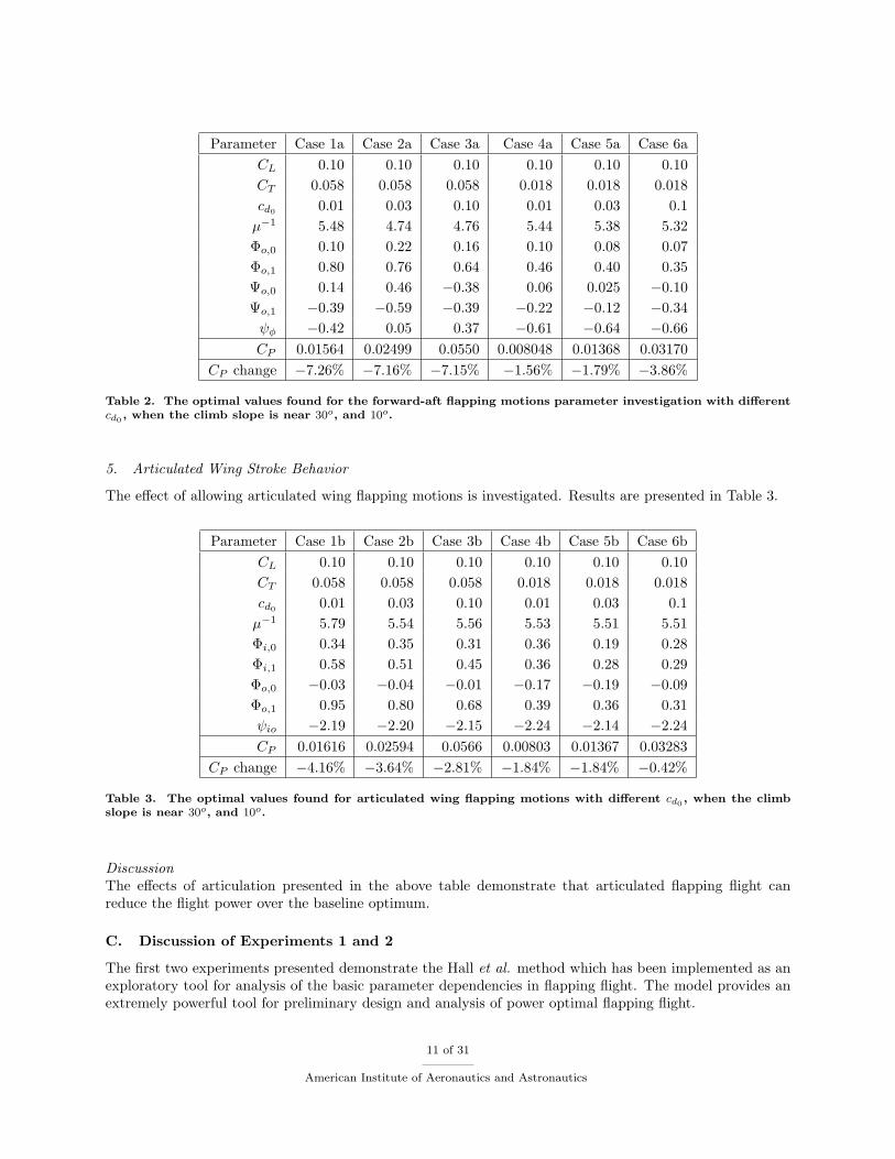
Parameter Case 1a Case 2a Case 3a Case 4a Case 5a Case 6aCL 0.10 0.10 0.10 0.10 0.10 0.10CT 0.058 0.058 0.058 0.018 0.018 0.018cd0 0.01 0.03 0.10 0.01 0.03 0.1µ−1 5.48 4.74 4.76 5.44 5.38 5.32Φo,0 0.10 0.22 0.16 0.10 0.08 0.07Φo,1 0.80 0.76 0.64 0.46 0.40 0.35Ψo,0 0.14 0.46 −0.38 0.06 0.025 −0.10Ψo,1 −0.39 −0.59 −0.39 −0.22 −0.12 −0.34ψφ −0.42 0.05 0.37 −0.61 −0.64 −0.66CP 0.01564 0.02499 0.0550 0.008048 0.01368 0.03170
CP change −7.26% −7.16% −7.15% −1.56% −1.79% −3.86%
Table 2. The optimal values found for the forward-aft flapping motions parameter investigation with differentcd0 , when the climb slope is near 30o, and 10o.
5. Articulated Wing Stroke Behavior
The effect of allowing articulated wing flapping motions is investigated. Results are presented in Table 3.
Parameter Case 1b Case 2b Case 3b Case 4b Case 5b Case 6bCL 0.10 0.10 0.10 0.10 0.10 0.10CT 0.058 0.058 0.058 0.018 0.018 0.018cd0 0.01 0.03 0.10 0.01 0.03 0.1µ−1 5.79 5.54 5.56 5.53 5.51 5.51Φi,0 0.34 0.35 0.31 0.36 0.19 0.28Φi,1 0.58 0.51 0.45 0.36 0.28 0.29Φo,0 −0.03 −0.04 −0.01 −0.17 −0.19 −0.09Φo,1 0.95 0.80 0.68 0.39 0.36 0.31ψio −2.19 −2.20 −2.15 −2.24 −2.14 −2.24CP 0.01616 0.02594 0.0566 0.00803 0.01367 0.03283
CP change −4.16% −3.64% −2.81% −1.84% −1.84% −0.42%
Table 3. The optimal values found for articulated wing flapping motions with different cd0 , when the climbslope is near 30o, and 10o.
DiscussionThe effects of articulation presented in the above table demonstrate that articulated flapping flight canreduce the flight power over the baseline optimum.
C. Discussion of Experiments 1 and 2
The first two experiments presented demonstrate the Hall et al. method which has been implemented as anexploratory tool for analysis of the basic parameter dependencies in flapping flight. The model provides anextremely powerful tool for preliminary design and analysis of power optimal flapping flight.
11 of 31
American Institute of Aeronautics and Astronautics
The results from the simulations presented demonstrate that the simpler models for flapping flight cancapture the essence of the problem using a minimal amount of computational resources. Although it isunlikely that the results from the simulations are quantitatively similar to natural flapping flight, it is likelythat the trends and qualitative results can be applied to natural flapping flight. Similar to the Trefftz planeanalysis for steady fixed wing aerodynamics,29 the modified wake-only Betz Criterion approach presentedby Hall et. al provides significant insight into efficient flapping flight.
V. Numerical Experiment 3
The last numerical experiment which is performed demonstrates the the process of designing an efficientflapping wing based on the solution of the Hall et. al. approach.
A. Generating a Flapping Wing Geometry From The Wake Solutions
There are several steps involved in translating the wake only representation of the wake into a three dimen-sional flapping wing model:
1. Construct a reference wing platform which flaps with the correct parameter dependence while sheddingthe least amount of vorticity possible into the domain. The wing can be designed to have a zero vorticityshedding throughout the wingbeat by instantaneous local modifications of section camber and angle ofattack. In this experiment, however, the wing is assumed to have a zero camber and the wing sectionis aligned with the flow at the leading edge. This assumption will produce a reference wing which hasnon-zero vorticity, especially in regions near the tip where incidence angles are important; however, asa first order approximation for demonstrating the translation process this is adequate.
2. Compute the downwash at lifting line positions along the wake considering only the vorticity down-stream of the lifting line.
3. Compute the local section angle of attack for the entire wing beat at each spanwise section of thewing. This is computed considering the optimal vorticity distribution in the wake from the Hall et. al.simulations.
4. Adjust the reference wing platform for the local downwash effects due to the wake as well as thelocal sectional angle of attack. The resulting geometry will have significant twist as the wing span istraversed during the flapping motions.
5. Mesh the flapping wing as either a thick body representation (using an airfoil profile) or as a thinmembrane. In this paper the thin membrane is considered due to the ease of meshing the geometry(especially near flapping joints).
1. Example Result
The following section demonstrates the conversion of a wake only simulation result to a FastAero flappingwing geometry which is used in a simulation of flapping flight. In figure 18(a) the optimum power wake vor-ticity distribution is presented. In figure 18(d) the wake trace is presented as a collection of vortex particleelements. The vortex particles demonstrate the features of the wake flow such as wake roll-up in the wingtipregions during the downstroke portion of the flapping. In figure 18(b) the wake structure is representedusing vortex particles. In this figure the vortex particle strength and direction is presented to demonstratethe vorticity structure in the wake.
Discussion The geometry was constructed from the optimal vorticity wake-only solution for the given wakeshape. Compared with the wake only simulation result in figure 18(a), the FastAero simulation (figures
12 of 31
American Institute of Aeronautics and Astronautics

18(d)-18(b)) shows similarities in the main wake features such as large tip vorticity during the downstroke;however, differences exist between the two wakes such as strong tip vorticity in the potential flow modelduring the upstroke, and some reduction in magnitude of vorticity on the inboard section of the wing duringthe downstroke. These differences are attributed in part to the approximate zero-lift flapping reference wingused as a foundation for the geometry description.
VI. Conclusions
In this paper, we have presented a computational framework capable of rapidly analyzing parametricdependencies in flapping flight. In the experiments, it was discovered that permitting additional parametersin the flapping kinematics description reduced the power required for flight. The power reduction wasdominant in more extreme flight cases such as situations where steep climb angles are encountered. This isnot surprising due to the competing objectives of lift and thrust production in these regimes. As a result,flapping motions which adjust the wake shape such that the fluid momentum increases during the downstrokeare most effectively used to propel and lift the flapping vehicle. As such, the forward-aft wing motions duringflapping flight are seen to be an effective means of adjusting the wake shape to minimize power consumptionduring steeper climbing flight.
In addition to basic parametric study examples, a presentation of the conversion of the wake only analysisto a potential flow solver is presented. Although the results do not illustrate a perfect match between thevortex wakes, the overall wake structure is preserved in the translation. In future investigations the conversionfrom a wake only analysis to a panel method representation will be modified for more accurate representation.Finally, with the ability to perform rapid parameter trade-offs using the wake only analysis of Hall et al. andsubsequent analysis in the FastAero panel method environment, further studies of parameter dependencewill be performed.
VII. Acknowledgments
The authors would like to express their gratitude to the Singapore-MIT Alliance, the National SciencesFoundation and the Natural Sciences and Engineering Research Council of Canada.
References
1Ellington, C.The aerodynamics of animal flight, American Zoology, Vol 24:95-105, 1984.2Rayner, J.M.V. A vortex theory of animal flight I. The vortex wake of a hovering animal, Journal of Fluid Mechanics,
Vol 91: pp697-730, 1979.3Rayner, J.M.V. A vortex theory of animal flight II. The forward flight of birds, Journal of Fluid Mechanics, Vol 91:
pp731-763, 1979.4Wang, J., Vortex shedding and frequency selection in flapping flight, Journal of Fluid Mechanics, vol. 410: pp 323-341,
2000.5Spedding, G.R.,The Wake of A Kestrel (Falco tinnunculus) in flapping flight, Journal of Experimental Biology,Vol
127:pp59-78, 1987.6Mittal, R, Immersed Boundary Methods, Annual Review of Fluid Mechanics, Vol. 37: 239-261, 2005.7Kirby, R.M., Warburton, T.c., Sherwin, S.J., Beskok, A., Karniadakis, G.E., The NeKTar Code: Dynamic Simulations
without Remeshing, 2nd Int’l Symposium on Computational Technologies for Fluid/Thermal/Chemical Systems with IndustrialApplications, August 1-5, 1999.
8Hall, K.C., Pigott, S.A., Power Requirements for Large-Amplitude Flapping Flight, AIAA Paper 97-0827, Presented atthe 35th Aerospace Sciences Meeting and Exhibit, Reno, NV, Jan. 6-9, 1997.
9Hall, S.R., Yang, K.Y., and Hall, K.C., Helicopter Rotor Lift Distributions for Minimum Induced Power Loss, Journalof Aircraft, Vol 31, No.4, pp837-845, 1994.
10Hall, K.C., and Hall, S.R., Minimum Induced Power Requirements for Flapping Flight, Journal of Fluid Mechanics, Vol.323, pp. 285-315, 1996.
11Hall, K.C., Pigott, S.A., Hall, S.R., Power Requirements for Large-Amplitude Flapping Flight, Journal of Aircraft, Vol35,No.3, May-June 1998
13 of 31
American Institute of Aeronautics and Astronautics

12Willis, D.J., Peraire, J., White, J.K., A Combined pFFT-multipole tree code, unsteady panel method with vortex particlewakes,43rd AIAA Aerospace Sciences Meeting and Exhibit, AIAA 2005-0854, Reno, NV, Jan. 2005.
13Norberg, U.M., Vertebrate Flight, Mechanics, Physiology, Morphology, Ecology and Evolution, Zoophysiology, Vol. 27,Springer, 1990.
14Pennychuick, C.J., Bird Flight Performance, a practical calculation manual,University Press, Oxford, 1989.15Bullen, R.D., and McKenzie, N.L. Scaling bat wingbeat frequency and amplitude, The journal of Experimental Biology
vol 205, pp2615-2626, 2002.16Spedding, G.R., Personal Communication, Brown University17Hendenstrom, A., Rosen, M., and Spedding, G.R. Vortex wakes generated by robins Erathacus rubecula during free flight
in a wind tunnel, Journal of The Royal Society Interface, Vol 3(7): pp 263-276, April 2006.18Alexander, D.E.,Nature’s Flyers: Birds, Insects, and the Biomechanics of Flight, The Johns Hopkins University Press,
2004.19Fletcher, R., Practical Methods of Optimization,2nd Ed., John Wiley and Sons, 2000.20Katanforoush, A., Unconstrained Optimization Library, math.ipm.ac.ir/scc/proglib.htm.21L. Greengard and V. Rohklin, A Fast Algorithm for Particle Simulations, J. Comp. Phys., 73:pp325-384, 1987.22Appel, A.A., An efficient program for many body simulations’, SIAM Journal of scientific and statistical computing, vol.
16, n. 1, pp85-103, 1985.23Voutsinas S.G., Belessis M.A., and Rados K.G., Investigation of the yawed operation of wind turbines by means of a
vortex particle method. AGARD-CP-552 FDP Symposium on Aerodynamics and Aeroacoustics of Rotorcraft, Berlin, Germany,Paper 11, 1995.
24Rehbach, C., Calcul numerique d’ecoulement tridimensionels instationaires avec nappes tourillonnaires, La RechercheAerospatiale, pp.289-298, 1977.
25G. S. Winckelmansand A. Leonard, Contributions to Vortex Particle Methods for the Computation of Three-DimensionalIncompressible Unsteady Flows, J. Comp. Phys, 109, pp 247-273, 1993.
26J. T. Beale, A. Majda, Vortex methods I: convergence in three dimensions, Math. Comput. 29 (159) 1-27, 1982.27Saad, Y., and Schultz, M.H. A generalized minimal residual algorithm for solving nonsymmetric linear systems. SIAM
Journal of Scientific and Statistical Computing, Vol 7, pp 856-869, 1986.28J. R. Philips and J. K. White, A Precorrected-FFT Method for Electrostatic Analysis of Complicated 3-D Structures,
IEEE Transactions On Computer-Aided Design of Integrated Circuits and Systems, IEEE, Vol. 16, 1997.29Ashley, H. and Landahl, M., Aerodynamics of Wings and Bodies, Addison-Wesley, Reading, MA, 1965.
14 of 31
American Institute of Aeronautics and Astronautics
(a) Baseline simple hinged harmonic flapping (b) Baseline simple hinged harmonic flapping.
(c) Baseline + forward-aft motions. (d) Baseline + forward-aft motions.
(e) Baseline + mid-wing articulation. (f) Baseline + mid-wing articulation.
Figure 2. An example of the diverse wake shapes possible using the harmonic flapping kinematics modelpresented in this paper. Direction of travel is from left to right.
15 of 31
American Institute of Aeronautics and Astronautics
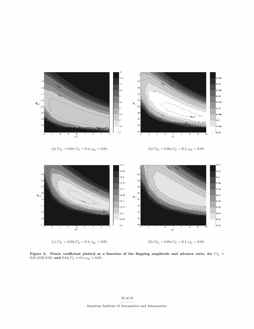
(a) CTi= 0.01, CL = 0.1, cd0 = 0.01. (b) CTi
= 0.02, CL = 0.1, cd0 = 0.01.
(c) CTi= 0.03, CL = 0.1, cd0 = 0.01. (d) CTi
= 0.04, CL = 0.1, cd0 = 0.01.
Figure 3. Power coefficient plotted as a function of the flapping amplitude and advance ratio, for CTi=
0.01, 0.02, 0.03, and 0.04, CL = 0.1, cd0 = 0.01.
16 of 31
American Institute of Aeronautics and Astronautics
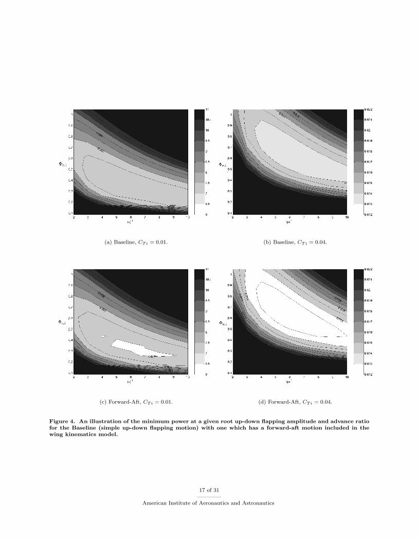
(a) Baseline, CTi = 0.01. (b) Baseline, CTi = 0.04.
(c) Forward-Aft, CTi = 0.01. (d) Forward-Aft, CTi = 0.04.
Figure 4. An illustration of the minimum power at a given root up-down flapping amplitude and advance ratiofor the Baseline (simple up-down flapping motion) with one which has a forward-aft motion included in thewing kinematics model.
17 of 31
American Institute of Aeronautics and Astronautics

(a) Top View. (b) Front View..
(c) Side View. (d) Perspective View.
Figure 5. An illustration of the optimal minimum power wake shape corresponding to forward aft-flappingmotions for CT = 0.01. Flight is from left to right.
18 of 31
American Institute of Aeronautics and Astronautics

(a) Top View. (b) Front View.
(c) Side View. (d) Perspective View.
Figure 6. An illustration of the optimal minimum power wake shape corresponding to forward aft-flappingmotions for CT = 0.04. Flight is from left to right.
19 of 31
American Institute of Aeronautics and Astronautics

(a) Baseline, CTi = 0.01. (b) Baseline, CTi = 0.04.
(c) Second Harmonic, CTi = 0.01. (d) Second Harmonic, CTi = 0.04
Figure 7. An illustration of the minimum power at a given root up-down flapping amplitude and advance ratiofor the Baseline (simple up-down flapping motion) with one which has a second harmonic included in the wingkinematics model.
20 of 31
American Institute of Aeronautics and Astronautics
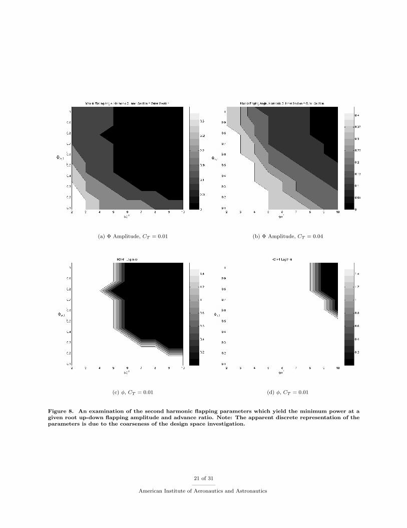
(a) Φ Amplitude, CT = 0.01 (b) Φ Amplitude, CT = 0.04
(c) φ, CT = 0.01 (d) φ, CT = 0.01
Figure 8. An examination of the second harmonic flapping parameters which yield the minimum power at agiven root up-down flapping amplitude and advance ratio. Note: The apparent discrete representation of theparameters is due to the coarseness of the design space investigation.
21 of 31
American Institute of Aeronautics and Astronautics

(a) Top View. (b) Front View.
(c) Side View. (d) Perspective View.
Figure 9. An illustration of the optimal minimum power wake shape corresponding to second harmonicmotionss for CT = 0.01. Flight is from left to right.
22 of 31
American Institute of Aeronautics and Astronautics
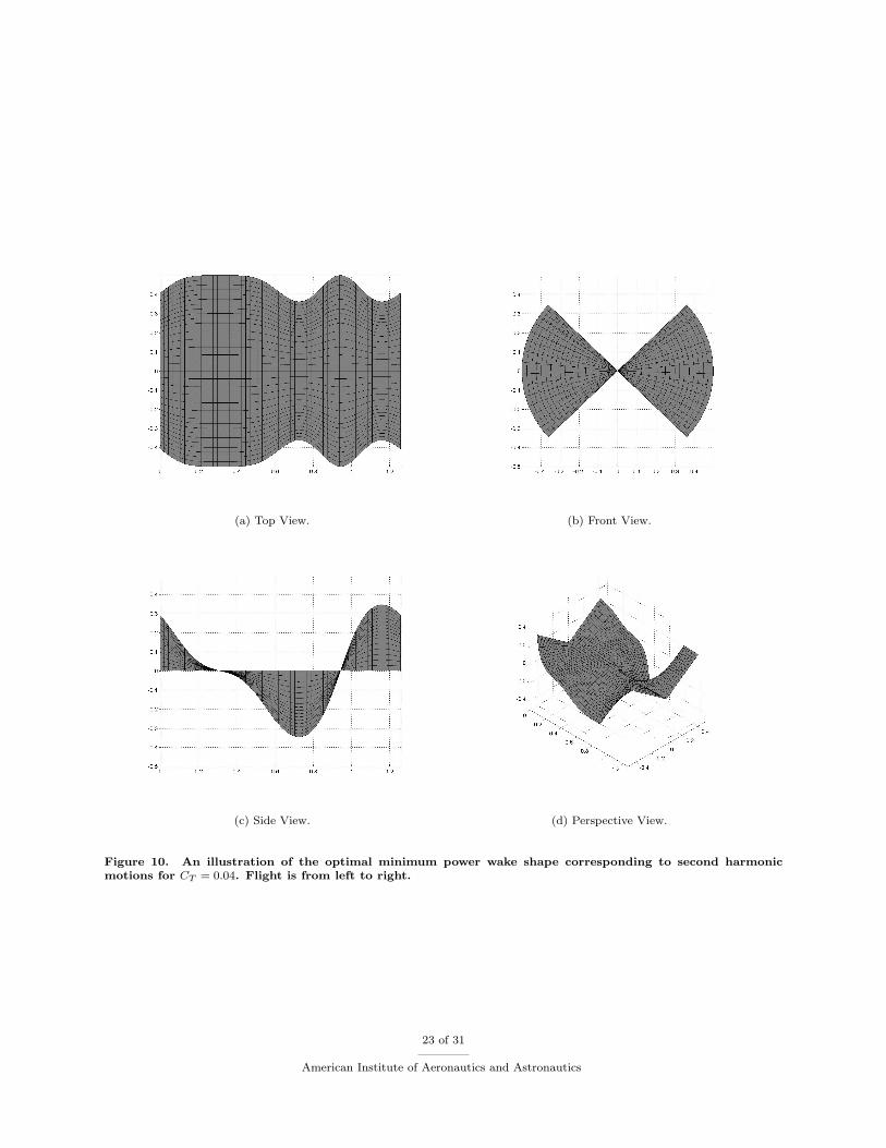
(a) Top View. (b) Front View.
(c) Side View. (d) Perspective View.
Figure 10. An illustration of the optimal minimum power wake shape corresponding to second harmonicmotions for CT = 0.04. Flight is from left to right.
23 of 31
American Institute of Aeronautics and Astronautics
(a) Baseline, CT = 0.01. (b) Baseline, CT = 0.04.
(c) Articulation, CT = 0.01. (d) Articulation, CT = 0.01.
Figure 11. An illustration of the minimum power at a given root up-down flapping amplitude and advanceratio for the Baseline (simple up-down flapping motion) with one which has a wing articulation at the wingquarter-span.
24 of 31
American Institute of Aeronautics and Astronautics
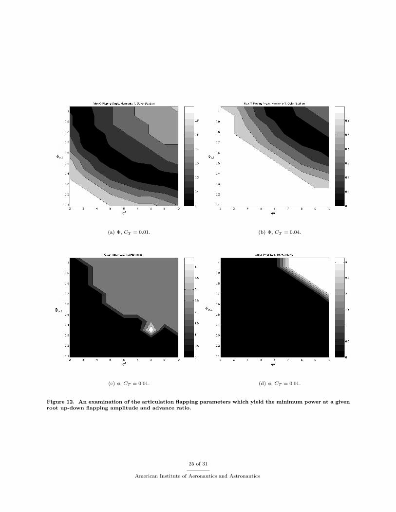
(a) Φ, CT = 0.01. (b) Φ, CT = 0.04.
(c) φ, CT = 0.01. (d) φ, CT = 0.01.
Figure 12. An examination of the articulation flapping parameters which yield the minimum power at a givenroot up-down flapping amplitude and advance ratio.
25 of 31
American Institute of Aeronautics and Astronautics

(a) Top View. (b) Front View.
(c) Side View. (d) Perspective View.
Figure 13. An illustration of the optimal minimum power wake shape corresponding to a quarter span wingarticulation for CT = 0.01. Flight is from left to right.
26 of 31
American Institute of Aeronautics and Astronautics
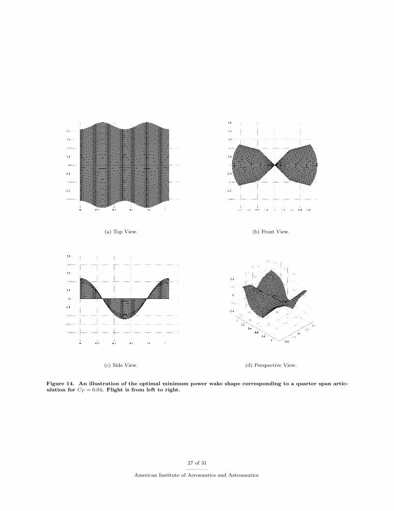
(a) Top View. (b) Front View.
(c) Side View. (d) Perspective View.
Figure 14. An illustration of the optimal minimum power wake shape corresponding to a quarter span artic-ulation for CT = 0.04. Flight is from left to right.
27 of 31
American Institute of Aeronautics and Astronautics
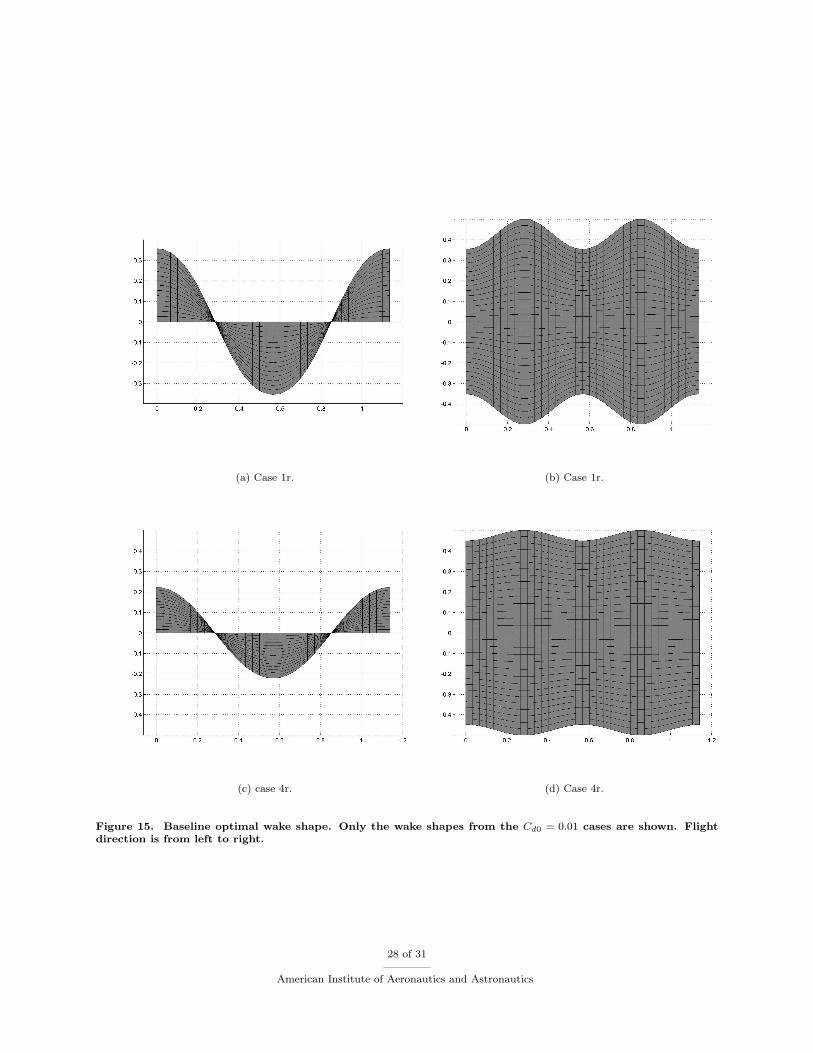
(a) Case 1r. (b) Case 1r.
(c) case 4r. (d) Case 4r.
Figure 15. Baseline optimal wake shape. Only the wake shapes from the Cd0 = 0.01 cases are shown. Flightdirection is from left to right.
28 of 31
American Institute of Aeronautics and Astronautics
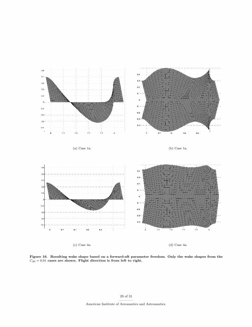
(a) Case 1a. (b) Case 1a.
(c) Case 4a. (d) Case 4a.
Figure 16. Resulting wake shape based on a forward-aft parameter freedom. Only the wake shapes from theCd0 = 0.01 cases are shown. Flight direction is from left to right.
29 of 31
American Institute of Aeronautics and Astronautics

(a) Case 1b. (b) Case 1b.
(c) Case 4b. (d) Case 4b.
Figure 17. The resulting optimal wake shapes for articulation degree of freedom for the different parametersearches. Only the wake shapes from the Cd0 = 0.01 cases are shown. Flight direction is from left to right.
30 of 31
American Institute of Aeronautics and Astronautics

(a) The reference wake from the wake only minimum powervorticity solution. Flight path is from right to left.
(b) A top view of the resulting FastAero simulation of aflapping geometry. Flight path is from right to left.
(c) An illustration of the vortex particle wake trailing aflapping wing, simulated using FastAero.
(d) An illustration of the vorticity in the wake trailing aflapping wing, simulated using FastAero.
Figure 18. A demonstration of the use of a wake only optimal vorticity distribution result to construct anefficient three-dimensional flapping wing geometry for simulation in an unsteady panel method solver.
31 of 31
American Institute of Aeronautics and Astronautics