a numerical and experimental study of microwave drying using a
TRANSCRIPT

A NUMERICAL AND EXPERIMENTAL
STUDY OF MICROWAVE DRYING
USING A RECTANGULAR WAVE GUIDE
P. Ratanadecho,* K. Aoki, and M. Akahori
Department of Mechanical Engineering, NagaokaUniversity of Technology, 1603-1, Kamitomioka,
Nagaoka, Niigata, 940-2188, Japan
ABSTRACT
The drying of a capillary porous packed bed of glass beads bymicrowave energy using a rectangular wave-guide was inves-tigated numerically and experimentally. The effects of moist-ure content, particle size and microwave power level on thedrying kinetics were examined. Most importantly, this workfocuses on the prediction of the distribution of the electro-magnetic field as well as the temperature and moisture distri-bution within the capillary porous medium. The model, whichcombines the electromagnetic, temperature, and moisturefields, predicted results which were in good agreement withthe experimental data.
Key Words: Electromagnetic field; Reflection; Capillaryporous packed bed; Dielectric materials
2209
Copyright & 2001 by Marcel Dekker, Inc. www.dekker.com
*Corresponding author. Nagaoka University of Technology, 1603-1, Kamitomioka,
Nagaoka, Niigata, 940-2188, Japan. E-mail: [email protected]
DRYING TECHNOLOGY, 19(9), 2209–2234 (2001)

2210 RATANADECHO, AOKI, AND AKAHORI
INTRODUCTION
A convenient starting point of drying theory is a recent work byWhitaker (1977), who derived locally volume averaged conservation equa-tions for two-phase capillary flow in porous media. A practical way todistinguish between the various drying processes is to classify them by theheating mode: convective drying, radiative drying, and conductive drying.Drying with internal heat generation, such as dielectric drying or microwavedrying, is a special case. See Mujumdar (1995) for a detailed discussion.
In the past decade, microwave technology has been applied to manyprocesses. Some of the successful examples of this application is in ceramicsprocessing for drying and sintering, drying of paper, freeze drying, andvulcanization of rubber. Refer to Metaxas and Meredith (1983) andSaltiel and Datta (1997) for an introduction to heat and mass transfer inmicrowave processing.
Simultaneous heat and mass transport in microwave drying wasstudied by Wei et al. (1985) with the aid of Lambert’s law, while Perkin etal. (1980) measured the temperature, moisture content, and pressure profilesin porous materials heated by microwave energy. Intensive microwavedrying has been studied by Turner and Jolly (1991), Turner and Ilic(1991), Constant et al. (1996) and Ni et al. (1999). A number of otherpossible analyses of conventional drying process and application of micro-wave process have appeared in the literatures (8)–(21).
Most previous work the microwave power absorbed was assumed todecay exponentially into the sample following the aid of Lambert’s law. Thisassumption is valid for the large dimensions of sample used in study. Forsmall samples, the spatial variations of the electromagnetic field and micro-wave power absorbed within sample must be obtained by a complete sol-ution of the unsteady Maxwell’s equations.
Due to the limited amount of theoretical and experimental work onmicrowave drying of capillary porous materials, the various effects are notfully understood and a number of critical issues remain unresolved. Thiseffects of reflection rate of microwave, degree of incident wave penetrationinto the sample, particle size and microwave power level during microwavedrying process etc. have not been studied systematically.
Although most of previous investigations considered one-dimensionalheat and mass transport little effort has been reported on study of two-dimensional drying process by microwave fields, especially, full comparisonbetween mathematical simulation results with experimental drying data.This study reports a comparison of predictions based on a two-dimensionalmodel with experimental measurement in which the microwave of TE10mode operating at a frequency of 2.45GHz is employed.

MICROWAVE DRYING WITH RECTANGULAR WAVE GUIDE 2211
Generally the variation of the microwave power level and change ofparticle size (glass bead size) during microwave drying of capillary porousmaterial could change the degree of penetration and rate of heat generationwithin the sample. Since the reflection rate of microwave strongly dependson the moisture content of the sample so that the effects of particle size andthe variation of microwave power level must be considered in this work. Thespecific objectives of this work are to
– formulate and solve the generalized mathematical model of dryingprocess by microwaves is purpose;
– compare the numerical results with experimental measurements
EXPERIMENTAL APPARATUS
Figure 1 shows the experimental apparatus used. The MW System wasa monochromatic wave of TE10 mode operating at a frequency of 2.45GHz.MW energy is transmitted along the z-direction of the rectangular waveguide with inside dimensions of 109.22 um� 54.61mm toward a waterload that is situated at the end of the wave guide. The water load (lowerabsorbing boundary) ensures that only a minimal amount of microwave isreflected back to the sample, while an upper absorbing boundary, whichis located at the end of wave guide, is used to trap any microwavereflected from the sample to prevent it from damaging the magnetron.The sample (capillary porous packed bed) studied is an initially saturatedrectangular packed bed, which is composed of glass beads and water witha bed thickness of 50mm. It is inserted in the rectangular wave guide.The container is made of polypropylene of 0.75mm thickness. The sampleporosity and permeability were measured. Dielectric properties of thesample at various conditions were measured (Von Hippel, 1954). Duringthe experiment, the weight of the sample, the ambient temperature, thetemperature of the sample at eight locations, the transmitted microwavepower, the reflected microwave power, and the microwave power absorbedby the sample were recorded by a data logger that was connected to acomputer.
The microwave field was generated using a magnetron (Micro DenshiCo., Model UM-1500). The powers of incident, reflected and transmittedwaves were measured by wattmeter using a directional coupler (MicroDenshi Co., model DR-5000). The temperature was measured with aLuxtron fluroptic thermometer model 790 (accurate to �0:5 8C).

2212 RATANADECHO, AOKI, AND AKAHORI
ANALYSIS OF MICROWAVE DRYING
USING RECTANGULAR WAVE GUIDE
Generally, studies of microwave drying involve solutions of the equa-tions governing electromagnetic propagation, i.e., Maxwell’s equations,either by themselves or coupled with the heat and mass transport equations.
(a) Equipment list.
(b) Rectangular porous packed bed
Microwave
0 x
54.61
50
y
z109.22
SaturatedPacked Beds
Figure 1. Schematic diagram of the microwave drying system.

MICROWAVE DRYING WITH RECTANGULAR WAVE GUIDE 2213
The objective of this work is to understand the phenomena of heat andmass transport during microwave drying of capillary porous packed bedby using rectangular wave guide. A two-dimensional analytical modelover the x–z plane in Figure 2 is presented. The surface of the sample isexposed to the external drying conditions. Microwave in the form of planewave incident this surface. Other surfaces are insulated and the heat andmoisture fluxes are set equal to zero.
Analysis of the Electromagnetic Field
Figure 2 shows the analytical model for microwave drying using arectangular wave guide. The model proposed is based on the followingassumptions:
1. Since the microwave field is of TE10 mode it propagates in arectangular wave guide independently of the y-direction. Hencethe electromagnetic field can be assumed to be two-dimensionalin the x–z plane.
2. The absorption of microwave energy by the cavity (including air)in the rectangular wave guide is negligible.
3. The walls of a rectangular wave guide are perfect conductors.4. The effect of the sample container on the electromagnetic field can
be neglected.
The basic equations for the electromagnetic field are the well knownMaxwell relations. When a microwave field propagates though an isotropicmediumhavingpermittivity",magneticpermeability�, electricconductivity�,
IncidentWave
yx
z0
Porous Material
Lx=109.22
50mm
Absorbing B.C
Absorbing B.C
Air
Perfect Cpmdictpr
Flow
Figure 2. Analytical model.

2214 RATANADECHO, AOKI, AND AKAHORI
and electric charge density q, the governing equations are as follows;
r � E ¼ ��@H
@tð1Þ
r �H ¼ �Eþ "@E
@tð2Þ
r � E ¼ q"
ð3Þ
r �H ¼ 0 ð4ÞFor the microwave of TE10 mode, the components of electric and
magnetic field intensities are given by
Ex ¼ Ez ¼ Hy ¼ 0Ey;Hx;Hz 6¼ 0
ð5Þ
where subscripts x, y and z represent x, y and z components of vectors,respectively. Taking into account Eq.(5), Eqs.(1)–(4) are written as, usingthe component notations of electric and magnetic field intensities,
@Ey@z
¼ �@Hx@t
ð6Þ
@Ey@x
¼ ��@Hz@t
ð7Þ
� @Hz@x
� @Hx@z
� �¼ �Ey þ "
@Ey@t
ð8Þ
where, permittivity ", magnetic permeability m and electric conductivity �are given by
" ¼ "0"r ð9Þ
� ¼ �0�r ð10Þ
� ¼ 2�f " tan � ð11Þwhere f is frequency of microwave, tand is the dielectric loss coefficient, "rand �r are relative permittivity and relative magnetic permeability, respect-ively. Further, because the dielectric properties are assumed to vary withtemperature and moisture content during the drying process, the dielectricproperties utilized throughout this study use the Wagner equation which canbe found in literature (Wang and Schmugge, 1990).

MICROWAVE DRYING WITH RECTANGULAR WAVE GUIDE 2215
Corresponding to the analytical model shown in Figure 2, boundaryconditions can be given as follows:
(a) Perfectly conducting boundariesBoundary conditions on the inner wall surface of a rectangular wave
guide are given using Faraday’s law and Gauss’ theorem, as
Et ¼ 0; Hn ¼ 0 ð12Þwhere subscripts t and n denote the components of tangential and normaldirections, respectively.(b) Continuity boundary condition
Boundary conditions along the interface between different materials,for example between air and dielectric material surface, are given as, usingAmpere’s law and Gauss theorem
Et ¼ E0t, Ht ¼ H
0t
Dn ¼ D0n, Bn ¼ B
0n
ð13Þ
where 0 denotes one of the different materials.(c) Absorbing boundary condition
At both ends of the rectangular wave guide, the first order absorbingconditions proposed by Mur (1981) are applied.
@Ey@t
¼ ��@Ey@z
ð14Þ
Here, the symbol � represents forward or backward waves and � isphase velocity of the microwave.(d) Oscillation of the electric and magnetic flied intensities by magnetron
Incident wave due to magnetron is given by the following equations.
Ey ¼ Eyin sin�x
Lx
� �sin 2�ftð Þ ð15Þ
Hx ¼Eyin
ZHsin
�x
Lx
� �sinð2�ftÞ ð16Þ
Eyin is the input value of electric field intensity, Lx is the length ofrectangular wave guide in x-direction, ZH is the wave impedance in caseswhere microwave propagates in rectangular wave guide, and can be repre-sented by
ZH ¼ �gZI�
¼ �g�
ffiffiffiffi�
"
rð17Þ

2216 RATANADECHO, AOKI, AND AKAHORI
where ZI depends on material and is called intrinsic impedance. � and �gare wave length of microwaves in free space and rectangular wave guide,respectively.
Analysis of Heat and Mass Transport
A schematic diagram of the model is shown in Figure 2. By conserva-tion of mass and energy in the sample, the governing equation of mass andenergy for all phases can be derived using the volume-averaging technique(Whitaker, 1977). The main transport mechanisms that enables moisturemovement during microwave drying of the sample are: liquid flow drivenby capillary pressure gradient and gravity while the vapor is driven by thegradient of the partial pressure of the evaporating species. The mainassumptions involved in the formulation of the transport model are:
1. The capillary porous material is rigid. No chemical reactions occurin the sample.
2. Local thermodynamics equilibrium is assumed.3. Simultaneous heat and mass transport occurs at constant pressure,
where the dominant mechanisms are capillary transport, vapordiffusion and gravity. Such is generally the case in drying of capil-lary porous medium at atmospheric pressure when the tempera-ture is lower than the boiling point (Bories, 1991).
4. The contribution of convection to energy transport is included.5. Corresponding to electromagnetic field, temperature and moisture
profiles also can be assumed to be two-dimensional in the x–z plane.6. The effect of the sample container on temperature and moisture
profiles can be neglected.
Mass Conservation
The microscopic mass conservation equations for liquid, water vapor,air, and gas phase, are written, respectively, as
Liquid phase �l@s
@tþ �l
@ul@x
þ �l@wl@z
¼ � n: ð18Þ
Vapor phase@
@t�vð1� sÞ� �þ @
@x�vuv½ � þ @
@z�vwv½ � ¼ n: ð19Þ
Air phase@
@t�að1� sÞ� �þ @
@x�aua½ � þ @
@z�awa½ � ¼ 0 ð20Þ

MICROWAVE DRYING WITH RECTANGULAR WAVE GUIDE 2217
Gas phase@
@t�gð1� sÞ� �þ @
@x�gug� �þ @
@z�gwg� � ¼ n: ð21Þ
Here n:is the evaporation rate during phase change and is the
porosity of porous medium. The water vapor and air mass flux is the sumof the convective term with the gas superficial velocity and diffusive term.
Energy Conservation
Ignoring kinetic energy and pressure terms which are usually unim-portant, this can be obtained from the total energy conservation for acombined solid, water vapor and air phase and by invoking the assumptionthat local thermodynamics equilibrium prevails among the all phases, thetemperature of the sample exposed to irradiation is obtained by solving theconventional heat transport equation with the microwave power absorbedincluded as a local electromagnetic heat generation term. The governingenergy equation describing the temperature rise in the sample is the timedependent equation is
@
@t½ð�cpÞTT � þ r f�lcplul þ ð�acpa þ �vcpvÞuggT
� �þHv n: ¼ �rqþQð22Þ
where Hv is the latent heat of vaporization of water and Q is the localelectromagnetic heat generation term, which is a function of the electricfield distribution and defined as
Q ¼ 2� � f � "0 � "rðtan �ÞE2y ð23Þwhere "r denotes relative dielectric constant, "0 denotes the permittivity offree space.
Phenomenological Relations
In order to complete the system of equations, the expressions for thesuperficial average velocity of the liquid and gas phases the generalizedDarcy’s law in the following form is used:
u*
l ¼ �KKrl�l
rpg � rpc � �l ~gg� � ð24Þ
u*
g ¼ �KKrg�g
rpg � �g~gg� � ð25Þ
2218 RATANADECHO, AOKI, AND AKAHORI
For the velocity of vapor water and air phase the generalized Fick’s law fora two components gas mixture can be expressed as:
�v ~uuv ¼ �v ~uug � �gDmr�v�g
� �ð26Þ
�a~uua ¼ �a~uug � �gDmr�a�g
� �ð27Þ
where the capillary pressure pc is related to the gas and liquid phases can bewritten by
pc ¼ pg � pl ð28Þand Dm is the effective molecular mass diffusion (Rogers and Kaviany, 1992)
Dm ¼ 2
3� ð1� sÞD ð29Þ
where D is the binary mass diffusion in plain media.Fourier’s law is used to define the heat flux through the porous
medium
q ¼ ��effrT ð30Þ
Equilibrium Relations
The system of conservation equations obtained for multiphase trans-port mode requires constitutive equation for relative permeabilities Kr,capillary pressure pc, capillary pressure functions (Leverett functions) J,and the effective thermal conductivity �eff . A typical set of constitutiverelationships for liquid and gas system given by:
Krl ¼ s3e ð31ÞKrg ¼ ð1� seÞ3 ð32Þ
where se is the effective water saturation considered the irreducible watersaturation sir and defined by
se ¼s� sir1� sir
ð33Þ
The capillary pressure pc is further assumed to be adequately repre-sented by Leverett’s well known JðseÞ functions. The relationship between

MICROWAVE DRYING WITH RECTANGULAR WAVE GUIDE 2219
the capillary pressure and the water saturation is defined using Leverettfunctions JðseÞ:
pc ¼ pg � pl ¼ffiffiffiffiffiffiffiffiffiK=
p JðseÞ ð34Þ
in which is the gas-liquid interfacial tension. Aoki et al. (1991) correlateddrainage capillary pressure data obtained by Leverett as follows to give JðseÞ:
JðseÞ ¼ 0:325ð1=se � 1Þ0:217 ð35Þ
The effective thermal conductivity of the capillary porous medium, �,is also a function of water saturation which can be written as:
�eff ¼0:8
1þ 3:78e�5:95s ð36Þ
State Equations
The gas phase is assumed to be an ideal mixture of perfect gases, sothat the species density can be determined by the state equations, with theclassical definitions for total density of the gas, �g, and the mass averagevelocity of the gas:
�a ¼paMa
RoT; �v ¼
pvMv
RoT
�g ¼ �a þ �v
pa ¼ �aRaT; pv ¼ �vRvT
pg ¼ pa þ pv�gug ¼ �aua þ �vuv ð37Þ
The partial pressure of the vapor was considered as a function of tempera-ture (Watanuki, 1998) and defined by
pv ¼ C0 þ ðC1 þ ðC2 þ ðC3 þ ðC4 þ C5TÞTÞTÞTÞT ð38Þ
where
C0 ¼ 610:8, C1 ¼ 43:87, C2 ¼ 1:47, C3 ¼ 0:025,C4 ¼ 2:88e� 4, C5 ¼ 2:71e� 6

2220 RATANADECHO, AOKI, AND AKAHORI
Moisture Transport Equation
The phenomenon ofmoisture transport in the sample is described by themass conservation equations for the liquid phase (equation 18) and the watervapor portion of the gas phase (equation 19) since it is the total water contentthat is of interest, these equations in two-dimensional scalar forms can beadded together to yield an equation for the total moisture content as follows:
@
@tf�lsþ �vð1� sÞg þ
@
@x½�lul þ �vuv� þ
@
@z½�lwl þ �vwv� ¼ 0 ð39Þ
Using Darcy’s generalized equation (equations 24,25) and Fick’s law(equations. 26,27), the moisture transport equation is written as:
@
@tf�lsþ�vð1�sÞgþ
@
@x�lKKrl�g
@pc@x
�@pg@x
þ�lgx
� �
þ�vKKrg�l
�@pg@x
þ�ggx
� ��Dm
@�v@x
þ @
@z�lKKrl�l
@pc@z
�@pg@z
þ�lgz
� �þ
�vKKrg�g
�@pg@z
þ�ggz
� ��Dm
@�v@z
¼0
ð40ÞIn addition, it is assumed that the total pressure gradient ð pg ¼ constÞ
and gravitational effect in x-direction are negligible. Thus, equation (40)becomes
@
@tf�lsþ �vð1� sÞg þ
@
@x�lKKrl�l
@pc@x
� ��Dm
@�v@x
þ @
@z�lKKrl�l
@pc@z
þ �lgz
� �þ
�vKKrg�g
ð�ggzÞ �Dm@�v@z
¼ 0
ð41Þ
Heat Transport Equation
For a nonisothermal flow we must add temperature as a dependentvariable. The conservation of energy equation for the two-dimensionalmodel allows prediction of the temperature. Thus, equation (22) leads to:
@
@tð�cpÞTT� �þ @
@xf�lcplulþð�acpaþ�vcpvÞuggT� �þ
@
@zf�lcplwlþð�acpaþ�vcpvÞwggT� �þHvn: ¼ @
@x�eff
@T
@x
þ @
@z�eff
@T
@z
þQð42Þ

MICROWAVE DRYING WITH RECTANGULAR WAVE GUIDE 2221
where
ð�cpÞT ¼ �lcplsþ fð�cpÞa þ ð�cpÞvgð1� sÞ þ �pcppð1� Þ ð43Þ
n: ¼ @
@tf�vð1� sÞg þ
@
@x�Dm
@�v@x
þ @
@z�vKKrg�g
�ggz �Dm@�v@z
ð44Þ
Boundary and Initial Conditions
There are two types of boundary conditions for solution of the gov-erning equations are formulated at the open and impermeable boundaries.
The boundary conditions proposed for the open boundary of thesample, for the exchange of energy at the open boundary can be describedin the following form:
��eff@T
@z¼ hcðT � T1Þ þ nHv ð45Þ
where hc is the local heat transfer coefficient.Mass transfer at the open boundary is modeled by means of a locally
constant mass transfer coefficient, which is related to the local water vaporflux density is described as:
�lwl þ �vwv ¼ hmsð�vs � �v1Þ ð46Þwhere hms is the local mass transfer coefficient, �vs is the density of watervapor at the open boundary and �v1 is reference vapor density in the gasphase surrounding the open boundary. Considering the boundary con-ditions at the closed boundary (symmetry-impermeable) that no heat andmass exchange take place:
@T
@x¼ @T
@z¼ 0 ð47Þ
@u
@x¼ @w
@z¼ 0 ð48Þ
The initial conditions are uniform initial temperature and moisture.
Numerical Procedure
In order to predict the electromagnetic field, a finite difference timedomain (FDTD) method is applied (Yee, 1966). The system of nonlinear

2222 RATANADECHO, AOKI, AND AKAHORI
partial differential equations (Equations. (41)–(48)) must be solved by themethod of finite differences based on the notion of control volumes asdescribed by Patankar (1980). At each time increment, the nodal value ofs and T were solved iteratively and convergence was checked on both vari-ables. The Newton-Raphson method was employed at each iteration toquicker the convergence. Initially, the temperature and moisture profileswere set to be equal at all nodes at values corresponding to the measuredcapillary porous medium conditions. Since the propagating velocity ofmicrowave is very fast compared with the rates of heat and mass transfer,different time steps of dt¼ 4 [ps] and 1[s] are used for the computation of theelectromagnetic field and temperature and moisture profile calculations. Thespatial step size is dx¼ dz¼ 1[mm]. Some of the input data for electromag-netic and thermo physical properties and drying conditions are given inTable 1 and Table 2, respectively.
RESULTS AND DISCUSSION
The experimental results for microwave drying of a capillary porouspacked bed (glass beadsþwater) were compared with mathematical model
Table 1. The Electromagnetic and Thermo Physical Properties Used in the
Computations
"0 ¼ 8:85419� 10�12½F=m�; �0 ¼ 4:0�� 10�7½H=m�"ra ¼ 1:0; "rp ¼ 5:1�ra ¼ 1:0; �rp ¼ 1:0; �rl ¼ 1:0tan �a ¼ 0:0; tan �p ¼ 0:01�a ¼ 1:205 ½kg=m3�; �p ¼ 2500:0 ½kg=m3�; �l ¼ 1000:0 ½kg=m3�cpa ¼ 1:007 ½kJ=ðkg �KÞ�; cpp ¼ 0:80 ½kJ=ðkg �KÞ�; cpl ¼ 4:186 ½kJ=ðkg �KÞ�
Table 2. The Drying Conditions Used in the Computations
Drying Conditions Value
Glass bead size, d [mm] 0.15, 0.4Initial saturation, So [�] 0.99Initial temperature, To [�C] 12
Irreducible saturation, Sir [�] 0.06Porosity, [�] 0.385, 0.371Air velocity, U1 (m/s) 7.2
Surrounding temperature, T1 [�C] 12
MICROWAVE DRYING WITH RECTANGULAR WAVE GUIDE 2223
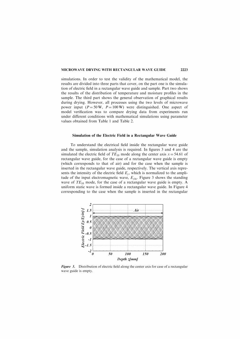
simulations. In order to test the validity of the mathematical model, theresults are divided into three parts that cover, on the part one is the simula-tion of electric field in a rectangular wave guide and sample. Part two showsthe results of the distribution of temperature and moisture profiles in thesample. The third part shows the general observation of graphical resultsduring drying. However, all processes using the two levels of microwavepower input (P¼ 50W, P¼ 100W) were distinguished. One aspect ofmodel verification was to compare drying data from experiments rununder different conditions with mathematical simulations using parametervalues obtained from Table 1 and Table 2.
Simulation of the Electric Field in a Rectangular Wave Guide
To understand the electrical field inside the rectangular wave guideand the sample, simulation analysis is required. In figures 3 and 4 are thesimulated the electric field of TE10 mode along the center axis x¼ 54.61 ofrectangular wave guide, for the case of a rectangular wave guide is empty(which corresponds to that of air) and for the case when the sample isinserted in the rectangular wave guide, respectively. The vertical axis repre-sents the intensity of the electric field Ey, which is normalized to the ampli-tude of the input electromagnetic wave, Eyin. Figure 3 shows the standingwave of TE10 mode, for the case of a rectangular wave guide is empty. Auniform static wave is formed inside a rectangular wave guide. In Figure 4corresponding to the case when the sample is inserted in the rectangular
Figure 3. Distribution of electric field along the center axis for case of a rectangular
wave guide is empty.

2224 RATANADECHO, AOKI, AND AKAHORI
wave guide, since the incident wave passing through the cavity having lowpermittivity is directly irradiated to the sample having high permittivity, amajor part of incident wave is reflected on the surface of the sample and thestanding waves form in the cavity forward to the sample. In early stage ofdrying, it is found that the electric field distribution within the sample arealmost extinguished. On the other hand, the electric field distribution for theend stage of drying process, in which case after a majority of the moisturelevel inside the sample is decreased, the effect of reflection rate on the surfaceof the sample is lower which increases the penetration depth of the micro-wave inside the sample.
Distribution of Temperature and Moisture
Profiles Within the Sample
Mathematical model simulation results are compared with experi-mental microwave drying data in Figures 5 through 11.
The temperature profile as a function of distance at various times for amicrowave power level of 100W are shown in Figure 5, which correspond tothose of initial temperature with 12�C, along with the center axisx¼ 54.61mm of rectangular wave guide. In contrast to that in conventionaldrying, microwave drying gives higher temperatures inside the dryingsample while the surface temperature stays colder due to the cooling effectof surrounding air. At the same time the evaporation takes place at the
Figure 4. Distribution of electric field along the center axis for the sample isinserted in the rectangular wave guide (t¼ 1min).

MICROWAVE DRYING WITH RECTANGULAR WAVE GUIDE 2225
surface of the sample at a lower temperature due to evaporative cooling. Thesimulated results are in agreement with the experimental results for micro-wave drying.
The temperature profiles at various times and at various distances areshown in Figures 6 and 7. Figure 6 shows that the temperature profile withinthe sample rises up quickly in the early stage of the drying process, after thatits rise slows down. In Figure 6, near the end stage of drying as the moisturecontent inside the sample is reduced, this decreases the microwave powerabsorbed resulting in a lower sample temperature. However, at a highmicrowave power input (100W) as shown in Figure 7, the temperatureprofile within the sample continuously rises faster than that in the case oflow microwave power input (50W). Also, the temperature remains high atthe end of drying. The simulated results are in good agreement with theexperimental results.
The following discussion refers to the effect of glass bead size undersame conditions. The temperature and moisture profiles are shown inFigures 8–11. Figure 8 shows the temperature profiles for two sizes(d¼ 0.15mm and d¼ 0.4mm). The observed temperature profiles at theleading edge of the sample in the case of small glass bead size are higherthan those in the case of larger size beads. This is because of the small glassbead size (which corresponds to a higher capillary force) can cause moistureto reach the surface at a higher rate than that in the case of larger beadsize (see Figure 10); this corresponds to a greater amount of microwavepower absorbed. Hence, even higher moisture content can lead to higher
Figure 5. Temperature as a function of distance at various times (P¼ 100W,d¼ 0.4mm, x¼ 54.61mm).

2226 RATANADECHO, AOKI, AND AKAHORI
temperatures in this region. On the other hand, for the case of the smallerbead size, the temperature profile deep inside the sample is still lower due tothe lower of moisture as well as microwave power absorbed inside thesample. Continued drying would eventually cause the average moisturecontent inside the sample to decrease and lead to decreased microwavepower absorbed, reduced temperature inside the sample; this is more sig-nificant in the case of smaller bead size (Figure 9).
Figure 6. Temperature profile in times at various distances (P¼ 50W, d¼ 0.15mm,x¼ 54.61mm).
Figure 7. Temperature profile in times at various distances (P¼ 100W, d¼ 0.4mm,x¼ 54.61mm).

MICROWAVE DRYING WITH RECTANGULAR WAVE GUIDE 2227
The variation of the drying rate with time obtained by simulation iscompared with the experimental results in Figure 11. The small bead size,however, leads to much higher capillary forces resulting in a shorter dryingtime and more uniform moisture profile inside the sample. The simulatedresults are in good agreement with the experimental results.
Figure 8. Comparison temperature as a function of distance (P¼ 100W,t¼ 90min, x¼ 54.61mm).
Figure 9. Comparison temperature as a function of distance (P¼ 50W,t¼ 180min, x¼ 54.61mm).

2228 RATANADECHO, AOKI, AND AKAHORI
General Observations on the Graphical Results
During Microwave Drying Process
The simulation results presented in the form of three-dimensional sur-face plots are considered in here. Figure 12 shows that in the early stages ofdrying, the temperature in the sample closest to the incoming microwaveand the distribution of temperature has a wavy shape corresponding to thatof electromagnetic field. This region heats up to a higher level at a faster ratethan elsewhere in the sample. Figure 13 shows that as the temperature insiderises to a higher level, the evaporation rate increases and the moisture isdriven quickly toward the surface where it evaporates and cools the surface.Figures 14 and 15 show the simulated moisture distributions within thesample for a microwave power input of 100W. Figure 14 shows that inthe early stages of the drying process, the moisture content at the leadingedge of the sample is lower than that inside the sample, where the moisturedecreases due to the gravitational effect. Because of the higher moisturecontent much larger reflected waves develop at the surface during theearly stages of the drying process. Later, the surface of the sample is sup-plied with liquid water through gradient in the capillary pressure, andbecause of the condensation of water vapor (which moves towards the sur-face due to a gradient in the vapor partial pressure), due to the lowertemperature of the surface. In Figure 15, continued drying would eventuallycause the average moisture content inside the sample to decrease and lead todecreased microwave power absorbed, reduced temperature and evapora-
Figure 10. Comparison water saturation as a function of distance (P¼ 100W,t¼ 90min, x¼ 54.61mm).

MICROWAVE DRYING WITH RECTANGULAR WAVE GUIDE 2229
tion rate. However, at longer times, the capillary pressure continues to pushinside the moisture to accumulate at the surface and it is slightly higher thanthat observed for moisture content inside the sample, especially, for the caseof small glass bead size (Figure 10). Nevertheless, the moisture content nowappears higher close to the walls of the sample.
Due to the large initial moisture content, the skin-depth heating effectcauses a major part of the incident wave to be reflected from the surface
Figure 11. The variation of drying rate with respect to time at (a) microwave power
input, P¼ 100W, (b) microwave power input, P¼ 50W.

2230 RATANADECHO, AOKI, AND AKAHORI
during the early stages of drying. This phenomenon explains why the ampli-tude of microwave within the sample in the early stage of drying is slightlylower than that observed in the final stage of drying and why the heating ismore intense close to the leading edge of the sample. Perre and Turner, (1997)reached the same conclusion for this phenomenon. However, continueddrying eventually causes the average moisture content inside the sample todecrease; the larger part of the microwave can then penetrate further into thesample compared with the early stage of drying.
Figure 12. Carpet plot of temperature distributions (t¼ 9min, P¼ 100W).
Figure 13. Carpet plot of temperature distributions (t¼ 90min, P¼ 100W).

MICROWAVE DRYING WITH RECTANGULAR WAVE GUIDE 2231
CONCLUSIONS
The experiments and theoretically analysis presented in this paper-describe many of the important interactions within a capillary porousmedium during microwave drying using a rectangular wave guide. Thefollowing summarizes the conclusions of this work:
1) A generalized mathematical model of drying by microwave usingrectangular wave guide is proposed. It is used successfully todescribe the drying phenomena under various conditions.
Figure 14. Carpet plot of moisture distributions (t¼ 9min, P¼ 100W).
Figure 15. Carpet plot of moisture distributions (t¼ 90min, P¼ 100W).

2232 RATANADECHO, AOKI, AND AKAHORI
2) The calculations of electromagnetic fields inside the rectangularwave guide and the sample show that the variation of microwavepower level and glass size changes the degree of penetration andrate of heat generation within the sample. The reflection rate ofmicrowave strongly depends on the amount of moisture contentwithin the sample.
3) The small bead size leads to much higher capillary forces resultingin a faster drying time.
4) At the longer drying times that the drying phenomenon is verycomplicated for the theoretical explanation, in situation where thematerials dry at certain locations and absorb microwave radiationmore efficiently at higher temperature due to dramatic increases indielectric loss coefficient, a local exponential rise in temperaturecan occur. This phenomenon, commonly referred to as thermalrunaway effect. Consequently, the dielectric properties databasemust be carefully used in the computational procedure. SeeRatanadecho et al. (2001) for a detail discussion.
NOMENCLATURE
Cp Specific heat capacity [J/kgK]E Electric field intensity [V/m]g Gravitational constant [m/s2]H Magnetic field intensity [A/m]P Microwave power input [W]Q Heat generation [W/m3]R Universal gas constant [J/mol/K]s Water saturation [�]T Temperature [ ]t Time [s]u Velocity [m/s]K Permeability [m2]M Molecular weight [kg/kg-mol]p Pressure [Pa]w Velocity [m/s]
Greek letters
Porosity [m3/m3]� Density [kg/m3]" Permittivity [F/m]

MICROWAVE DRYING WITH RECTANGULAR WAVE GUIDE 2233
� Free space wave length [m]� Magnetic permeability [H/m]� Velocity of propagation [m/s]�eff Effective conductivity [W/mK]�g Dynamic viscosity of gas [Pa s]�l Dynamic viscosity of liquid [Pa s]
Subscripts
0 Free spacea Airc Capillaryg Gasp Particler Relativev Water vaporl Liquid waterx, y, z Coordinates
REFERENCES
1. Aoki, K., Hattori, M., Kitamura, M. and Shiraishi, N., 1991,Characteristics of heat Transport in Porous Media with WaterInfiltration, ASME/JSME Thermal Engineering Proceedings, Vol. 4,pp. 303–308.
2. Bories, S.A., 1991, Fundamental of drying of capillary-porous bodies,pp. 39–434, in Kakac, S., Kilkis, B., Kulacki, F. and Arinc, F. (Ed.),Convective heat and mass transfer in porous media. NATO ASI series,Vol. 196, Kluwer Publishers.
3. Constant, T., Moyne, C. and Perre, P., 1996, Drying with internal heatgeneration: Theoretical aspects and application to microwave heating,AIChE J., 42 (2) pp. 359–368.
4. Mur, G., 1981, Absorbing boundary conditions for the Finite-DifferenceApproximation of the Time-Domain Electromagnetic-Field Equations,IEEE Transactions of Electromagnetic Compatibility, EMC-23 (4) pp.377–382.
5. Metaxas, A.C. and Meridith, R.J., 1983, Industrial Microwave Heating,Peter Peregrinus, Ltd., London.
6. Mujumdar, A.S. (Ed.), 1995, Handbook of Industrial Drying, 2ndEdition, Marcel Dekker, New York.

2234 RATANADECHO, AOKI, AND AKAHORI
7. Ni, H., Datta, A. and Torrance, K.E., 1999, Moisture transport in
intensive microwave heating of biomaterials: a multiphase porous
media model, Int. J. Heat and Mass Transfer, 42 (8) pp. 1501–1512.
8. Perre, P. and Turner, W., 1997, Microwave Drying of softwood in an
Oversized Waveguide, AIChE J., 43 (10) pp. 2579–2595.
9. Patankar, S.V., 1980 Numerical Heat Transfer and Fluid Flow,
Hemisphere Publishing Corporation, New York.
10. Rogers, J.A. and Kaviany, M., 1992, Funicular and evaporative-front
regimes in convective drying of granular beds, Int. J. Heat and Mass
Transfer, 35 (2) pp. 469–479.
11. Ratanadecho, P., Aoki, K. and Akahori, M., 2001, Experimental and
numerical study of microwave drying in unsaturated porous material,
Int. Communication. Heat Mass Trans, Vol 28 (5), pp. 605–616.
12. Ratandecho, P., Aoki, K. and Akahori, M., 2001, Influence of irradia-
tion time, particle sizes and initial moisture content during microwave
drying of multi-layered capillary porous materials, ASME J. Heat
Transfer (to be published).
13. Saltiel, C. and Datta, A., 1990, Heat and mass transfer in microwave
processing, Adv. Heat Transfer, pp. 3–15.
14. Turner, I.W. and Jolly, P.G., 1990, The effect of dielectric properties on
microwave drying kinetics, J. Microwave power and electromagnetic
energy, 25 (1) 30 (4) pp. 221–223.
15. Turner, I.W. and Jolly, P.G., 1991, Combined microwave and convec-
tive drying of a porous material, Drying Technology, 9 (5) pp. 1209–
1269.
16. Von Hippel, A.R., 1954, Dielectric Materials and Applications, MIT
Press, Boston.
17. Wei, C.K., Davis, H.T., Davis, E.A. and Gordon, J., 1985, Heat and
mass transfer in water-laden sand stone: microwave heating, AIChE J.,
31 (5) pp. 842–848.
18. Watanuki, J., 1998, Fundamental study of Microwave Heating with
Rectangular Wave guide, M.S. Thesis (In Japanese), Nagaoka
University of Technology, Japan 85 p.
19. Wang, J. and Schmugge, T., 1980, An empirical model for the complex
dielectric permittivity of soil as a function of water content, IEEE
Transactions on Geosciences and Remote Sensing, GE-18 (4) pp. 288–295.
20. Whitaker, S., 1977, A theory of drying in porous media, Adv. Heat
Transfer (13), pp. 119–203.
21. Yee, K.S., 1966, Numerical solution of initial boundary value problems
involving Maxwell’s equation in isotropic media, IEEE Transactions of
Antennas Propagation, AP-14 pp. 302–307.