a novel high-performance gel polymer electrolyte membrane basing on electrospinning technique for...
TRANSCRIPT

Ae
NK
a
ARRAA
KTPEG
1
rlao�npocesWpeg
tsptc
0d
Journal of Power Sources 196 (2011) 8638– 8643
Contents lists available at ScienceDirect
Journal of Power Sources
jou rna l h omepa g e: www.elsev ier .com/ locate / jpowsour
novel high-performance gel polymer electrolyte membrane basing onlectrospinning technique for lithium rechargeable batteries
a Wu, Qi Cao ∗, Xianyou Wang, Xiaoyun Li, Huayang Dengey Laboratory of Environmentally Friendly Chemistry and Applications of Minister of Education, College of Chemistry, Xiangtan University, Xiangtan 411105, China
r t i c l e i n f o
rticle history:eceived 5 January 2011eceived in revised form 10 March 2011ccepted 21 April 2011vailable online 21 June 2011
a b s t r a c t
Nonwoven films of composites of thermoplastic polyurethane (TPU) with different proportion ofpoly(vinylidene fluoride) (PVdF) (80, 50 and 20%, w/w) are prepared by electrospinning 9 wt% poly-mer solution at room temperature. Then the gel polymer electrolytes (GPEs) are prepared by soaking theelectrospun TPU–PVdF blending membranes in 1 M LiClO4/ethylene carbonate (EC)/propylene carbonate
−3 −1
eywords:hermoplastic polyurethane (TPU)oly(vinylidene fluoride) (PVdF)lectrospinningel polymer electrolyte
(PC) for 1 h. The gel polymer electrolyte (GPE) shows a maximum ionic conductivity of 3.2 × 10 S cmat room temperature and electrochemical stability up to 5.0 V versus Li+/Li for the 50:50 blend ratio ofTPU:PVdF system. At the first cycle, it shows a first charge–discharge capacity of 168.9 mAh g−1 when thegel polymer electrolyte (GPE) is evaluated in a Li/PE/lithium iron phosphate (LiFePO4) cell at 0.1 C-rateat 25 ◦C. TPU–PVdF (50:50, w/w) based gel polymer electrolyte is observed much more suitable than thecomposite films with other ratios for high-performance lithium rechargeable batteries.
© 2011 Elsevier B.V. All rights reserved.
. Introduction
Over the past decades, gel polymer electrolytes (GPEs) haveeceived extensive attention and been investigated widely inithium-ion batteries [1–5]. GPEs are formed by adsorbing a certainmount of liquid electrolyte in a polymer framework. Several meth-ds have been tried to get GPEs such as phase inversion method,-ray irradiation method, solvent casting technique, TIPS tech-ique, and electrospinning technique. Among these methods, theolymer electrolytes prepared by electrospinning technique notnly own good mechanical properties but also show high ioniconductivity [6–8]. Electrospinning is an alternative, simple andfficient process which is at least one or two order of magnitudemaller than the fibers produced from melt or solution spinning.
hen adopting electrospinning technique, many interconnectedores will be formed in the porous membrane, so enough liquidlectrolytes were absorbed by the polymer membrane formingelled polymer electrolytes.
Thermoplastic polyurethane (TPU) has two-phase microstruc-ure: the soft segments and the hard segments [9,10]. The hardegments are interconnected throughout the soft phase parts, and
lay the role of keeping the GPEs’ dimensional stability. Whilehe soft segments dissolve alkali metal without formation of ionicluster and offer the whole system with good ionic conductivity.∗ Corresponding author. Tel.: +86 731 58298090; fax: +86 731 58298090.E-mail address: [email protected] (Q. Cao).
378-7753/$ – see front matter © 2011 Elsevier B.V. All rights reserved.oi:10.1016/j.jpowsour.2011.04.062
Many researchers also focus attention on the TPU copolymerizedwith other polymer hosts in the preparation of gel polymer elec-trolytes. There have been some reports on the use of thermoplasticpolyurethane (TPU)/polyacrylonitrile (PAN) (TPU–PAN), thermo-plastic polyurethane (TPU)/linear poly(ethylene oxide) (PEO)(TPU–PEO) and polyurethane/poly(vinylidene fluoride) (PU–PVDF)for rechargeable lithium batteries [11–13]. With high mechanicaland anodically stability, poly(vinylidene fluoride), PVdF has beenadopted as polymer electrolytes in lithium batteries [14,15,19].The TPU-co-PVdF based GPEs not only have relatively high ionicconductivity, but also have good mechanical stability at roomtemperature. The strong electron-withdrawing functional group(–C–F) which is in the backbone structure of PVdF can formhydrogen bonds with amino-group (–NH) which is in the hardsegments of TPU. Therefore, PVdF and TPU are miscible withoutany microphase separation as electrospun matrix for gel polymerelectrolytes (GPEs).
In this paper, we prepare TPU–PVdF blending polymer elec-trolyte membranes by electrospinning using 9 wt% polymersolution with different weight ratio of TPU/PVdF. And then thenonwoven films are activated by immersing into 1 M LiClO4–EC/PCliquid electrolyte solution at room temperature in a glove box. Weinvestigate the ionic conductivity and electrochemical properties,the cycle performances and the rate capabilities of these electro-
spun fibrous polymer electrolytes for lithium ion batteries. Primaryresults show that this kind of polymer electrolyte membrane hasexcellent enhancement in performance as GPE for lithium ion bat-teries.
er Sou
2
2
pvR7qtTat
2
di9vfit1
2
∼fitsm
2
mtTof
irmn
wUfi
Sn0niırt
2
v
N. Wu et al. / Journal of Pow
. Experimental
.1. Materials
Thermoplastic polyurethane (TPU, yantaiwanhua, 1190A) andoly(vinylidene fluoride) (PVdF, Alfa Aesar) were dried underacuum at 80 ◦C for 24 h. LiClO4·3H2O (AR, Sinopharm Chemicaleagent Co. Ltd.) was dehydrated in vacuum oven at 120 ◦C for2 h. 1.0 M Liquid electrolyte was made by dissolving a certainuality of LiClO4 in ethylene carbonate (EC, Shenzhen capchemechnology Co. Ltd.)/propylene carbonate (PC, Shenzhen capchemechnology Co. Ltd.) (1/1, v/v). N,N-dimethylforamide (DMF) andcetone were analytical purity and used as received without furtherreatment.
.2. Preparation of TPU–PVdF fibrous membrane
A certain amount of TPU and PVdF powder as a unit withifferent weight ratio (80:20; 50:50 and 20:80) were dissolved
n N,N-dimethylacetamide (DMF)/acetone (3:1, w/w) forming a wt% solution, separately. The solution was electrospun under higholtage of 24.5 kV at room temperature, respectively. Nonwovenlms were obtained on the collector plate. The TPU–PVdF elec-rospun nonwoven films were dried under vacuum at 80 ◦C for2 h.
.3. Preparation of gel polymer electrolytes
The thickness of the TPU–PVdF nonwoven films used were100 �m. At room temperature, the dried TPU–PVdF nonwovenlms were activated by dipping in 1 M LiClO4–EC/PC liquid elec-rolyte solutions for 1 h in a glove box filled with argon. Wipe theurface of swelled membranes by filter paper and then get gel poly-er electrolytes.
.4. Membrane characterization
The morphology of films was examined by Scanning electronicroscope (SEM, Hitachi S-3500N, Japan). The thermal stability of
he films was monitored using thermogravimetric analysis (modelQAQ 50, TA Company, USA). The TGA measurements were carriedut under dry nitrogen atmosphere at a heating rate of 20 ◦C min−1
rom 30 to 900 ◦C.The porosity was investigated by immersing the membranes
nto n-butanol for 1 h and then calculated by using the followingelation: P = (Ww − Wd/�bVp) × 100%, where Ww and Wd are theass of the wet and dry membrane, respectively, �b the density of
-butanol, and vp the volume of the dry membrane.The electrolyte uptake was determined [16] by measuring the
eight increase and calculated according to the following Eq. (A):ptake (%) = (W − W0/W0) × 100%, where W0 is the weight of driedlms and W is the weight of swelled films.
The ionic conductivity of the composite film was measured withS/PE/SS blocking cell by AC impedance measurement using Zah-er Zennium electrochemical analyzer with a frequency range of.1–1 MHz. The thin films were prepared about 100 �m in thick-ess and 2.24 cm2 in area for impedance measurement. Thus, the
onic conductivity could be calculated from the following Eq. (B): = (h/RbS). In this equation, ı is the ionic conductivity, Rb is the bulkesistance, h and S is the thickness and area of the films, respec-ively.
.5. Cell assembly and performance characteristics
Electrochemical stability was measured by a linear sweepoltammetry (LSV) of a Li/PE/SS cell using Zahner Zennium elec-
rces 196 (2011) 8638– 8643 8639
trochemical analyzer at a scan rate of 5 mV s−1, with voltage from2.5V-6 V. For charge–discharge cycling tests, the Li/PE/LiFePO4 cellwas assembled. The LiFePO4 cathode was prepared as its blendwith acetylene black and PVdF binder at a ratio of 85:10:5 byweight. A certain amount of these three powers were mixedtogether in N-methylpyrrolidone (NMP) solvent to get homoge-neous slurry which was cast on the shell of the cell and driedunder vacuum at 80 ◦C for 24 h. The cell was subjected to electro-chemical performance tests using an automatic charge–dischargeunit, Neware battery testing system (model BTS-51, ShenZhen,China), between 2.5 and 4.2 V at 25 ◦C, at a current densities of0.1 C.
3. Results and discussion
3.1. Morphology and structure
Fig. 1 shows the morphology of the prepared porous electro-spun TPU/PVdF membranes with different weight ratio. It is clearlythat the membranes are made up of a network of interlaid andnearly straightened tubular structure fibers. Electrospun TPU/PVdFfibrous membrane with 20 wt% of PVdF in the composite (Fig. 1A)has a structure with an average fiber diameter (AFD) of ∼1.2 �m. Asshown in Fig. 1B, TPU/PVdF (50:50, w/w) nonwoven film (Fig. 1B)has interconnected multifibrous layers with ultrafine porous struc-ture. The AFDs of TPU/PVdF (50:50, w/w) nonwoven films aremuch more uniformly about ∼0.57 �m, which is half size of thefiber diameters in TPU/PVdF (80:20, w/w) membrane. AlthoughTPU/PVdF (20:80, w/w) membrane in Fig. 1C has a narrowest fiberdiameter range, there are many beads in the fiber membrane.
All of the fibers mentioned above appear to be uniform in com-position without having any microphase separation which due tothe miscibility of TPU and PVdF. However the good miscibility ofTPU and PVdF dues to the special chemical structure of TPU [17,18].Generally speaking, TPU is a linear polymer material. Its molecu-lar structure is complicated, containing ether groups, ester groupsand duplicated carbamated–chain (–R′–O–CO–NH–R–NH–CO–O–).The duplicated carbamated-chain (–R′–O–CO–NH–R–NH–CO–O–),which is in the hard segments of TPU, offers amino-group (–NH). Sothe strong electron-withdrawing functional group (–C–F) which isin the backbone structure of PVdF can form hydrogen bonds withamino-group (–NH). Therefore, PVdF and TPU are miscible withoutany microphase separation as electrospun matrix for gel polymerelectrolytes (GPEs).
It is well known that the parameters of influencing the mor-phology of electrospun fiber membranes are the distance betweenthe nozzle of the syringe and the collector, the applied voltage,the concentration of the polymer solution and dielectric constantof the solution. In this study, the first three factors in the abovelist were kept as a constant while electrospinning. So they can-not be the reasons for the morphological differences. Upon that weenvisage the following reasons. The increased content of PVdF hasbeen attributed to increasing dielectric constant of the medium forelectrospinning. Electrospun jets are easily formed at the nozzleof the syringe for TPU–PVdF composite solution and cause forma-tion of fibers with lower diameter. However the incorporation ofPVdF increases, the viscosity and surface tension of the solutiondecreases. The droplets of the solution have got to the collectorbefore the solvent evaporates completely. This is the reason for theformation of beads structure in Fig. 1C.
Kim et al. had reported decreasing in average fiber diameters can
result in a decrease in leakage rate [19,20]. This particular structuremay result in high electrolyte uptake. The presence of fully inter-connected pores in the structure makes them suitable as a hostmatrix for the preparation of gel polymer electrolytes.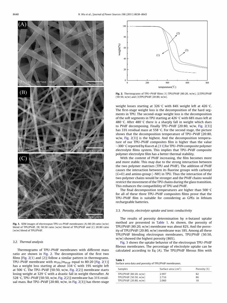
8640 N. Wu et al. / Journal of Power Sources 196 (2011) 8638– 8643
Fig. 1. SEM images of electrospun TPU-co-PVdF membranes (A) 80:20 ratio (w/w)b(
3
rfiThal5u
w/w) showed the highest porosity (86%).Fig. 3 shows the uptake behavior of the electrospun TPU–PVdF
fibrous membranes. The percentage of electrolyte uptake can becalculated according to Eq (A). The TPU/PVdF fibrous film with
Table 1Surface area data and porosity of TPU/PVdF membranes.
Samples Surface area (cm2) Porosity (%)
lend of TPU/PVdF, (B) 50:50 ratio (w/w) blend of TPU/PVdF and (C) 20:80 ratiow/w) blend of TPU/PVdF.
.2. Thermal analysis
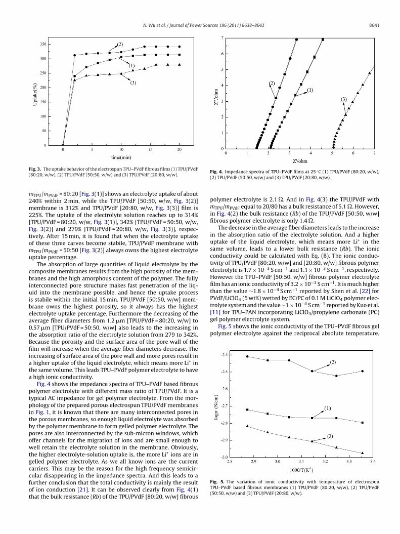
Thermograms of TPU–PVdF membranes with different massatio are shown in Fig. 2. The decomposition of the first twolms [Fig. 2(1) and (2)] follow a similar pattern in thermograms.PU–PVdF membrane with mTPU/mPVdF equal to 80:20 [Fig. 2(1)]as a weight loss starting at about 334 ◦C with 19% weight leftt 506 ◦C. The TPU–PVdF [50:50, w/w, Fig. 2(2)] membrane starts
osing weight at 329 ◦C with a drastic fall in weight thereafter. At28 ◦C, TPU–PVdF [50:50, w/w, Fig. 2(2)] membrane has 31% resid-al mass. But TPU–PVdF [20:80, w/w, in Fig. 2(3)] has three-stageFig. 2. Thermograms of TPU–PVdF films (1) TPU/PVdF (80:20, w/w), (2)TPU/PVdF(50:50, w/w) and (3)TPU/PVdF (20:80, w/w).
weight losses starting at 326 ◦C with 84% weight left at 426 ◦C.The first-stage weight loss is the decomposition of the hard seg-ments in TPU. The second-stage weight loss is the decompositionof the soft segments in TPU starting at 426 ◦C with 68% mass left at480 ◦C. After 480 ◦C there is a sharply fall in weight which duesto PVdF decomposing. Finally TPU–PVdF [20:80, w/w, Fig. 2(3)]has 33% residual mass at 558 ◦C. For the second stage, the pictureshows that the decomposition temperature of TPU–PVdF [20:80,w/w, Fig. 2(3)] is the highest. And the decomposition tempera-ture of our TPU–PVdF composites film is higher than the value∼300 ◦C reported by Kuo et al. [11] for TPU–PAN composite polymerelectrolyte films system. This implies that TPU–PVdF compositepolymer electrolyte film has a better thermal stability.
With the content of PVdF increasing, the film becomes moreand more stable. This may due to the strong interaction betweenthe two polymer matrixes (TPU and PVdF). The addition of PVdFcauses the interaction between its fluorine groups with carbonyl(C O) and amino-group (–NH) in TPU. Thus the interaction of thetwo polymer chains would be stronger and the PVdF chains wouldrestrict the movement of the TPU chains during the glass transition.This enhances the compatibility of TPU and PVdF.
The final decomposition temperatures are higher than 500 ◦Cfor all of these three TPU–PVdF composites films prove that theTPU–PVdF film is suitable for considering as GPEs in lithiumrechargeable batteries.
3.3. Porosity, electrolyte uptake and ionic conductivity
The results of porosity determination by n-butanol uptakemethod are presented in Table 1. As shown, the porosity ofTPU/PVdF (80:20, w/w) membrane was about 82%. And the poros-ity of TPU/PVdF (20:80, w/w) membrane was 18%. Among all theseTPU/PVdF blending electrospun membranes, TPU/PVdF (50:50,
TPU/PVdF (80:20, w/w) 2.997 82TPU/PVdF (50:50, w/w) 2.716 86TPU/PVdF (20:80, w/w) 2.060 18
N. Wu et al. / Journal of Power Sources 196 (2011) 8638– 8643 8641
F(
m2m2[Ftomu
cbiuibea0tBfiiata
ptpitbpowtgccfot
gel polymer electrolyte system.Fig. 5 shows the ionic conductivity of the TPU–PVdF fibrous gel
polymer electrolyte against the reciprocal absolute temperature.
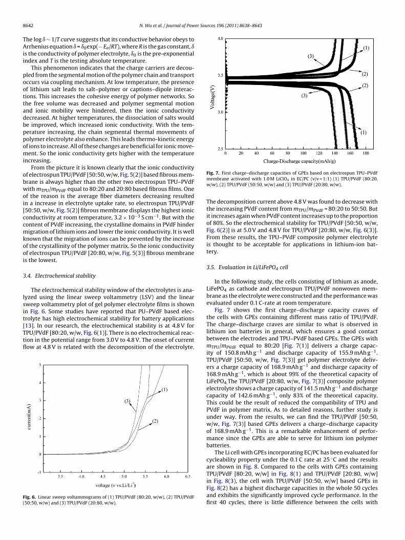
ig. 3. The uptake behavior of the electrospun TPU–PVdF fibrous films (1) TPU/PVdF80:20, w/w), (2) TPU/PVdF (50:50, w/w) and (3) TPU/PVdF (20:80, w/w).
TPU/mPVdF = 80:20 [Fig. 3(1)] shows an electrolyte uptake of about40% within 2 min, while the TPU/PVdF [50:50, w/w, Fig. 3(2)]embrane is 312% and TPU/PVdF [20:80, w/w, Fig. 3(3)] film is
25%. The uptake of the electrolyte solution reaches up to 314%TPU/PVdF = 80:20, w/w, Fig. 3(1)], 342% [TPU/PVdF = 50:50, w/w,ig. 3(2)] and 279% [TPU/PVdF = 20:80, w/w, Fig. 3(3)], respec-ively. After 15 min, it is found that when the electrolyte uptakef these three carves become stabile, TPU/PVdF membrane withTPU/mPVdF = 50:50 [Fig. 3(2)] always owns the highest electrolyteptake percentage.
The absorption of large quantities of liquid electrolyte by theomposite membranes results from the high porosity of the mem-ranes and the high amorphous content of the polymer. The fully
nterconnected pore structure makes fast penetration of the liq-id into the membrane possible, and hence the uptake process
s stabile within the initial 15 min. TPU/PVdF [50:50, w/w] mem-rane owns the highest porosity, so it always has the highestlectrolyte uptake percentage. Furthermore the decreasing of theverage fiber diameters from 1.2 �m [TPU/PVdF = 80:20, w/w] to.57 �m [TPU/PVdF = 50:50, w/w] also leads to the increasing inhe absorption ratio of the electrolyte solution from 279 to 342%.ecause the porosity and the surface area of the pore wall of thelm will increase when the average fiber diameters decrease. The
ncreasing of surface area of the pore wall and more pores result in higher uptake of the liquid electrolyte, which means more Li+ inhe same volume. This leads TPU–PVdF polymer electrolyte to have
high ionic conductivity.Fig. 4 shows the impedance spectra of TPU–PVdF based fibrous
olymer electrolyte with different mass ratio of TPU/PVdF. It is aypical AC impedance for gel polymer electrolyte. From the mor-hology of the prepared porous electrospun TPU/PVdF membranes
n Fig. 1, it is known that there are many interconnected pores inhe porous membranes, so enough liquid electrolyte was absorbedy the polymer membrane to form gelled polymer electrolyte. Theores are also interconnected by the sub-micron windows, whichffer channels for the migration of ions and are small enough toell retain the electrolyte solution in the membrane. Obviously,
he higher electrolyte-solution uptake is, the more Li+ ions are inelled polymer electrolyte. As we all know ions are the currentarriers. This may be the reason for the high frequency semicir-ular disappearing in the impedance spectra. And this leads to a
urther conclusion that the total conductivity is mainly the resultf ion conduction [21]. It can be observed clearly from Fig. 4(1)hat the bulk resistance (Rb) of the TPU/PVdF [80:20, w/w] fibrousFig. 4. Impedance spectra of TPU–PVdF films at 25 ◦C (1) TPU/PVdF (80:20, w/w),(2) TPU/PVdF (50:50, w/w) and (3) TPU/PVdF (20:80, w/w).
polymer electrolyte is 2.1 �. And in Fig. 4(3) the TPU/PVdF withmTPU/mPVdF equal to 20/80 has a bulk resistance of 5.1 �. However,in Fig. 4(2) the bulk resistance (Rb) of the TPU/PVdF [50:50, w/w]fibrous polymer electrolyte is only 1.4 �.
The decrease in the average fiber diameters leads to the increasein the absorption ratio of the electrolyte solution. And a higheruptake of the liquid electrolyte, which means more Li+ in thesame volume, leads to a lower bulk resistance (Rb). The ionicconductivity could be calculated with Eq. (B). The ionic conduc-tivity of TPU/PVdF [80:20, w/w] and [20:80, w/w] fibrous polymerelectrolyte is 1.7 × 10⁻³ S cm−1 and 1.1 × 10⁻³ S cm−1, respectively.However the TPU–PVdF [50:50, w/w] fibrous polymer electrolytefilm has an ionic conductivity of 3.2 × 10⁻³ S cm−1. It is much higherthan the value ∼1.8 × 10⁻⁴ S cm−1 reported by Shen et al. [22] forPVdF/LiClO4 (5 wt%) wetted by EC/PC of 0.1 M LiClO4 polymer elec-trolyte system and the value ∼1 × 10⁻⁴ S cm−1 reported by Kuo et al.[11] for TPU–PAN incorporating LiClO4/propylene carbonate (PC)
Fig. 5. The variation of ionic conductivity with temperature of electrospunTPU–PVdF based fibrous membranes (1) TPU/PVdF (80:20, w/w), (2) TPU/PVdF(50:50, w/w) and (3) TPU/PVdF (20:80, w/w).
8 er Sources 196 (2011) 8638– 8643
TAii
poottadbppomi
obwoi[ccmkooi
3
lsit[Ttfl
F(
642 N. Wu et al. / Journal of Pow
he log ı ∼ 1/T curve suggests that its conductive behavior obeys torrhenius equation ı = ı0exp(− Ea/RT), where R is the gas constant, ı
s the conductivity of polymer electrolyte, ı0 is the pre-exponentialndex and T is the testing absolute temperature.
This phenomenon indicates that the charge carriers are decou-led from the segmental motion of the polymer chain and transportccurs via coupling mechanism. At low temperature, the presencef lithium salt leads to salt–polymer or captions–dipole interac-ions. This increases the cohesive energy of polymer networks. Sohe free volume was decreased and polymer segmental motionnd ionic mobility were hindered, then the ionic conductivityecreased. At higher temperatures, the dissociation of salts woulde improved, which increased ionic conductivity. With the tem-erature increasing, the chain segmental thermal movements ofolymer electrolyte also enhance. This leads thermo-kinetic energyf ions to increase. All of these changes are beneficial for ionic move-ent. So the ionic conductivity gets higher with the temperature
ncreasing.From the picture it is known clearly that the ionic conductivity
f electrospun TPU/PVdF [50:50, w/w, Fig. 5(2)] based fibrous mem-rane is always higher than the other two electrospun TPU–PVdFith mTPU/mPVdF equal to 80:20 and 20:80 based fibrous films. One
f the reason is the average fiber diameters decreasing resultedn a increase in electrolyte uptake rate, so electrospun TPU/PVdF50:50, w/w, Fig. 5(2)] fibrous membrane displays the highest ioniconductivity at room temperature, 3.2 × 10⁻³ S cm−1. But with theontent of PVdF increasing, the crystalline domains in PVdF hinderigration of lithium ions and lower the ionic conductivity. It is well
nown that the migration of ions can be prevented by the increasef the crystallinity of the polymer matrix. So the ionic conductivityf electrospun TPU/PVdF [20:80, w/w, Fig. 5(3)] fibrous membranes the lowest.
.4. Electrochemical stability
The electrochemical stability window of the electrolytes is ana-yzed using the linear sweep voltammetry (LSV) and the linearweep voltammetry plot of gel polymer electrolyte films is shownn Fig. 6. Some studies have reported that PU–PVdF based elec-rolyte has high electrochemical stability for battery applications
13]. In our research, the electrochemical stability is at 4.8 V forPU/PVdF [80:20, w/w, Fig. 6(1)]. There is no electrochemical reac-ion in the potential range from 3.0 V to 4.8 V. The onset of currentow at 4.8 V is related with the decomposition of the electrolyte.ig. 6. Linear sweep voltammograms of (1) TPU/PVdF (80:20, w/w), (2) TPU/PVdF50:50, w/w) and (3) TPU/PVdF (20:80, w/w).
Fig. 7. First charge–discharge capacities of GPEs based on electrospun TPU–PVdFmembrane activated with 1.0 M LiClO4 in EC/PC (v/v = 1:1) (1) TPU/PVdF (80:20,w/w), (2) TPU/PVdF (50:50, w/w) and (3) TPU/PVdF (20:80, w/w).
The decomposition current above 4.8 V was found to decrease withthe increasing PVdF content from mTPU/mPVdF = 80:20 to 50:50. Butit increases again when PVdF content increases up to the proportionof 80%. So the electrochemical stability for TPU/PVdF [50:50, w/w,Fig. 6(2)] is at 5.0 V and 4.8 V for TPU/PVdF [20:80, w/w, Fig. 6(3)].From these results, the TPU–PVdF composite polymer electrolyteis thought to be acceptable for applications in lithium-ion bat-tery.
3.5. Evaluation in Li/LiFePO4 cell
In the following study, the cells consisting of lithium as anode,LiFePO4 as cathode and electrospun TPU/PVdF nonwoven mem-brane as the electrolyte were constructed and the performance wasevaluated under 0.1 C-rate at room temperature.
Fig. 7 shows the first charge–discharge capacity craves ofthe cells with GPEs containing different mass ratio of TPU/PVdF.The charge–discharge craves are similar to what is observed inlithium ion batteries in general, which ensures a good contactbetween the electrodes and TPU–PVdF based GPEs. The GPEs withmTPU/mPVdF equal to 80:20 [Fig. 7(1)] delivers a charge capac-ity of 150.8 mAh g−1 and discharge capacity of 155.9 mAh g−1.TPU/PVdF [50:50, w/w, Fig. 7(3)] gel polymer electrolyte deliv-ers a charge capacity of 168.9 mAh g−1 and discharge capacity of168.9 mAh g−1, which is about 99% of the theoretical capacity ofLiFePO4.The TPU/PVdF [20:80, w/w, Fig. 7(3)] composite polymerelectrolyte shows a charge capacity of 141.5 mAh g−1 and dischargecapacity of 142.6 mAh g−1, only 83% of the theoretical capacity.This could be the result of reduced the compatibility of TPU andPVdF in polymer matrix. As to detailed reasons, further study isunder way. From the results, we can find the TPU/PVdF [50:50,w/w, Fig. 7(3)] based GPEs delivers a charge–discharge capacityof 168.9 mAh g−1. This is a remarkable enhancement of perfor-mance since the GPEs are able to serve for lithium ion polymerbatteries.
The Li cell with GPEs incorporating EC/PC has been evaluated forcycleability property under the 0.1 C rate at 25 ◦C and the resultsare shown in Fig. 8. Compared to the cells with GPEs containingTPU/PVdF [80:20, w/w] in Fig. 8(1) and TPU/PVdF [20:80, w/w]
in Fig. 8(3), the cell with TPU/PVdF [50:50, w/w] based GPEs inFig. 8(2) has a highest discharge capacities in the whole 50 cyclesand exhibits the significantly improved cycle performance. In thefirst 40 cycles, there is little difference between the cells with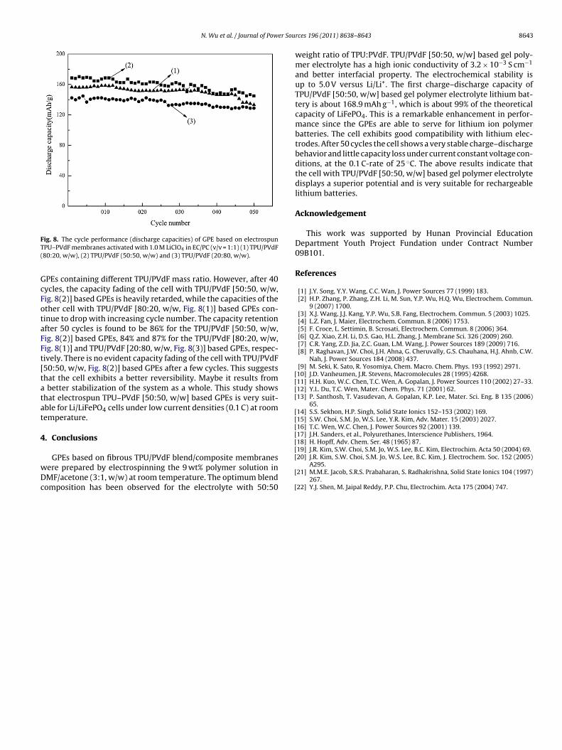
N. Wu et al. / Journal of Power Sou
FT(
GcFotaFFt[tatat
4
wDc
[[[[
[[[[[[
ig. 8. The cycle performance (discharge capacities) of GPE based on electrospunPU–PVdF membranes activated with 1.0 M LiClO4 in EC/PC (v/v = 1:1) (1) TPU/PVdF80:20, w/w), (2) TPU/PVdF (50:50, w/w) and (3) TPU/PVdF (20:80, w/w).
PEs containing different TPU/PVdF mass ratio. However, after 40ycles, the capacity fading of the cell with TPU/PVdF [50:50, w/w,ig. 8(2)] based GPEs is heavily retarded, while the capacities of thether cell with TPU/PVdF [80:20, w/w, Fig. 8(1)] based GPEs con-inue to drop with increasing cycle number. The capacity retentionfter 50 cycles is found to be 86% for the TPU/PVdF [50:50, w/w,ig. 8(2)] based GPEs, 84% and 87% for the TPU/PVdF [80:20, w/w,ig. 8(1)] and TPU/PVdF [20:80, w/w, Fig. 8(3)] based GPEs, respec-ively. There is no evident capacity fading of the cell with TPU/PVdF50:50, w/w, Fig. 8(2)] based GPEs after a few cycles. This suggestshat the cell exhibits a better reversibility. Maybe it results from
better stabilization of the system as a whole. This study showshat electrospun TPU–PVdF [50:50, w/w] based GPEs is very suit-ble for Li/LiFePO4 cells under low current densities (0.1 C) at roomemperature.
. Conclusions
GPEs based on fibrous TPU/PVdF blend/composite membranesere prepared by electrospinning the 9 wt% polymer solution inMF/acetone (3:1, w/w) at room temperature. The optimum blendomposition has been observed for the electrolyte with 50:50
[
[
[
rces 196 (2011) 8638– 8643 8643
weight ratio of TPU:PVdF. TPU/PVdF [50:50, w/w] based gel poly-mer electrolyte has a high ionic conductivity of 3.2 × 10⁻³ S cm−1
and better interfacial property. The electrochemical stability isup to 5.0 V versus Li/Li+. The first charge–discharge capacity ofTPU/PVdF [50:50, w/w] based gel polymer electrolyte lithium bat-tery is about 168.9 mAh g−1, which is about 99% of the theoreticalcapacity of LiFePO4. This is a remarkable enhancement in perfor-mance since the GPEs are able to serve for lithium ion polymerbatteries. The cell exhibits good compatibility with lithium elec-trodes. After 50 cycles the cell shows a very stable charge–dischargebehavior and little capacity loss under current constant voltage con-ditions, at the 0.1 C-rate of 25 ◦C. The above results indicate thatthe cell with TPU/PVdF [50:50, w/w] based gel polymer electrolytedisplays a superior potential and is very suitable for rechargeablelithium batteries.
Acknowledgement
This work was supported by Hunan Provincial EducationDepartment Youth Project Fundation under Contract Number09B101.
References
[1] J.Y. Song, Y.Y. Wang, C.C. Wan, J. Power Sources 77 (1999) 183.[2] H.P. Zhang, P. Zhang, Z.H. Li, M. Sun, Y.P. Wu, H.Q. Wu, Electrochem. Commun.
9 (2007) 1700.[3] X.J. Wang, J.J. Kang, Y.P. Wu, S.B. Fang, Electrochem. Commun. 5 (2003) 1025.[4] L.Z. Fan, J. Maier, Electrochem. Commun. 8 (2006) 1753.[5] F. Croce, L. Settimin, B. Scrosati, Electrochem. Commun. 8 (2006) 364.[6] Q.Z. Xiao, Z.H. Li, D.S. Gao, H.L. Zhang, J. Membrane Sci. 326 (2009) 260.[7] C.R. Yang, Z.D. Jia, Z.C. Guan, L.M. Wang, J. Power Sources 189 (2009) 716.[8] P. Raghavan, J.W. Choi, J.H. Ahna, G. Cheruvally, G.S. Chauhana, H.J. Ahnb, C.W.
Nah, J. Power Sources 184 (2008) 437.[9] M. Seki, K. Sato, R. Yosomiya, Chem. Macro. Chem. Phys. 193 (1992) 2971.10] J.D. Vanheumen, J.R. Stevens, Macromolecules 28 (1995) 4268.11] H.H. Kuo, W.C. Chen, T.C. Wen, A. Gopalan, J. Power Sources 110 (2002) 27–33.12] Y.L. Du, T.C. Wen, Mater. Chem. Phys. 71 (2001) 62.13] P. Santhosh, T. Vasudevan, A. Gopalan, K.P. Lee, Mater. Sci. Eng. B 135 (2006)
65.14] S.S. Sekhon, H.P. Singh, Solid State Ionics 152–153 (2002) 169.15] S.W. Choi, S.M. Jo, W.S. Lee, Y.R. Kim, Adv. Mater. 15 (2003) 2027.16] T.C. Wen, W.C. Chen, J. Power Sources 92 (2001) 139.17] J.H. Sanders, et al., Polyurethanes, Interscience Publishers, 1964.18] H. Hopff, Adv. Chem. Ser. 48 (1965) 87.19] J.R. Kim, S.W. Choi, S.M. Jo, W.S. Lee, B.C. Kim, Electrochim. Acta 50 (2004) 69.
20] J.R. Kim, S.W. Choi, S.M. Jo, W.S. Lee, B.C. Kim, J. Electrochem. Soc. 152 (2005)A295.21] M.M.E. Jacob, S.R.S. Prabaharan, S. Radhakrishna, Solid State Ionics 104 (1997)
267.22] Y.J. Shen, M. Jaipal Reddy, P.P. Chu, Electrochim. Acta 175 (2004) 747.