a novel dental bridge design
TRANSCRIPT

1
A NOVEL DENTAL BRIDGE DESIGN
A thesis submitted to the University of Manchester
for the degree of Master of Philosophy in the
faculty of medical and human sciences
2012
AHMED BINOBAID
SCHOOL OF DENTISTRY
2
List of Contents
Section Pg
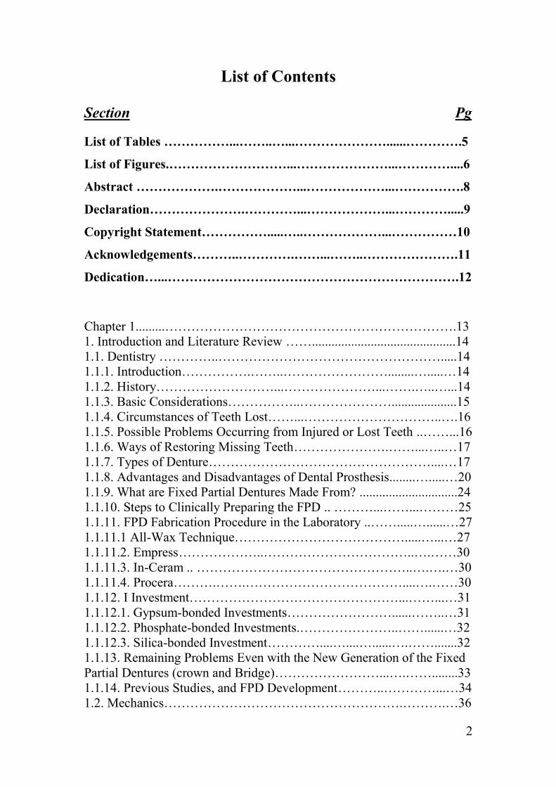
List of Tables ……………...……..…...…………………......………….5
List of Figures.………………………...…………………...…………....6
Abstract ……………….………………...………………...…………….8
Declaration………………….…………...………………...………….....9
Copyright Statement…………….....…..………………...……………10
Acknowledgements………..………….……...……..………………….11
Dedication…...………………………………………………………….12
Chapter 1.........………………………………………………………….13
1. Introduction and Literature Review ……............................................14
1.1. Dentistry …………..…………………………………………….....14
1.1.1. Introduction…………….……..……………………........….....…14
1.1.2. History………………………...…………………...…….…..…...14
1.1.3. Basic Considerations……………..…………………....................15
1.1.4. Circumstances of Teeth Lost……...…………………………..….16
1.1.5. Possible Problems Occurring from Injured or Lost Teeth ..……...16
1.1.6. Ways of Restoring Missing Teeth………………….……...…..…17
1.1.7. Types of Denture……………………………………………....…17
1.1.8. Advantages and Disadvantages of Dental Prosthesis........….....…20
1.1.9. What are Fixed Partial Dentures Made From? ..............................24
1.1.10. Steps to Clinically Preparing the FPD .. ………...……...………25
1.1.11. FPD Fabrication Procedure in the Laboratory ..…….....…......…27
1.1.11.1 All-Wax Technique………………………………….....…...…27
1.1.11.2. Empress………………..……………………………..….……30
1.1.11.3. In-Ceram .. …………………………………………..….….…30
1.1.11.4. Procera……….…….………………………………....….……30
1.1.12. I Investment…………………………………………...……...…31
1.1.12.1. Gypsum-bonded Investments……………………......……..…31
1.1.12.2. Phosphate-bonded Investments.…………………..……......…32
1.1.12.3. Silica-bonded Investment…………....…....…......….…….......32
1.1.13. Remaining Problems Even with the New Generation of the Fixed
Partial Dentures (crown and Bridge)……………………...….……........33
1.1.14. Previous Studies, and FPD Development………..…………...…34
1.2. Mechanics……………………………………………….……….…36
3
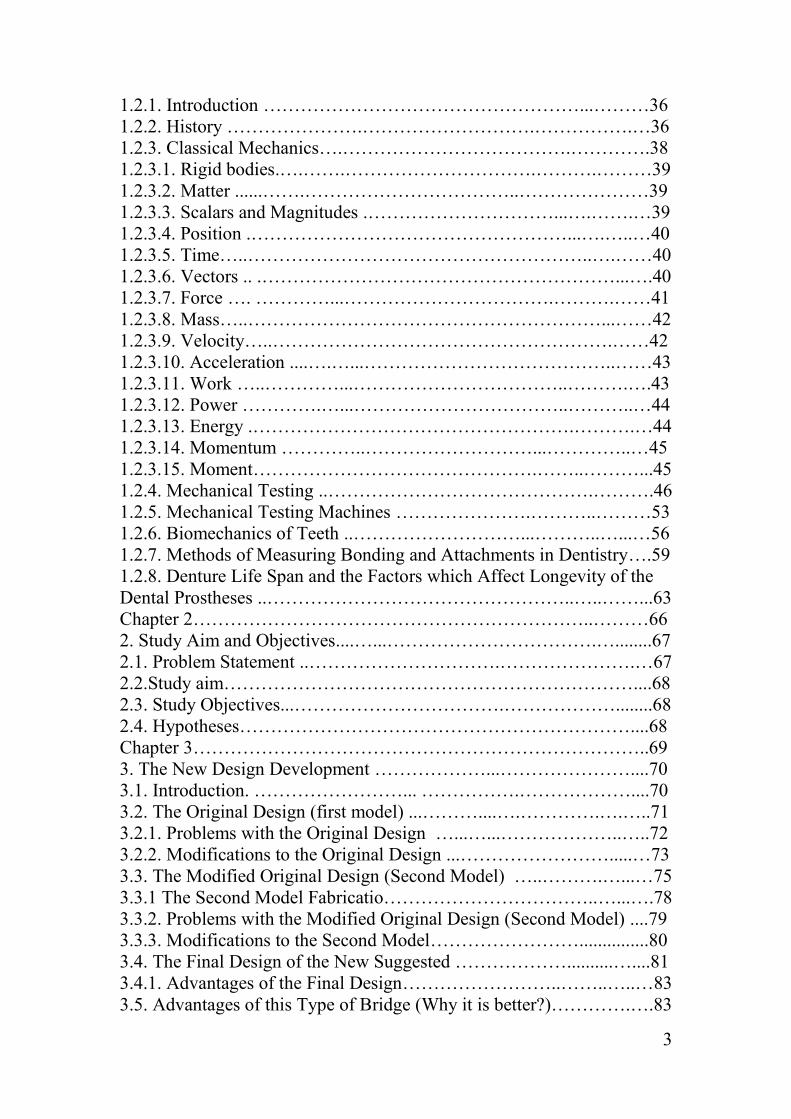
1.2.1. Introduction ……………………………………………...………36
1.2.2. History ………………….……………………….…………….…36
1.2.3. Classical Mechanics….……………………………….………….38
1.2.3.1. Rigid bodies.….…….………………………….……….………39
1.2.3.2. Matter ......…….……………………………..…………………39
1.2.3.3. Scalars and Magnitudes .…………………………...….…….…39
1.2.3.4. Position .……………………………………………...….…..…40
1.2.3.5. Time…..………………………………………………..….……40
1.2.3.6. Vectors .. .…………………………………………………...….40
1.2.3.7. Force …. …………...…………………………….……….……41
1.2.3.8. Mass…..…………………………………………………...……42
1.2.3.9. Velocity…..……………………………………………….……42
1.2.3.10. Acceleration ....….…...…………………………………..……43
1.2.3.11. Work …..…………...……………………………..……….….43
1.2.3.12. Power ………….…...……………………………..………..…44
1.2.3.13. Energy .…………………………………………….……….…44
1.2.3.14. Momentum …………..………………………...…………..…45
1.2.3.15. Moment……………………………………….……..………...45
1.2.4. Mechanical Testing ..…………………………………….……….46
1.2.5. Mechanical Testing Machines ………………….………..………53
1.2.6. Biomechanics of Teeth ..………………………...………..…...…56
1.2.7. Methods of Measuring Bonding and Attachments in Dentistry….59
1.2.8. Denture Life Span and the Factors which Affect Longevity of the
Dental Prostheses ..…………………………………………..…..……...63
Chapter 2………………………………………………………..………66
2. Study Aim and Objectives....…...…………………………….…........67
2.1. Problem Statement ..………………………….………………….…67
2.2.Study aim…………………………………………………………....68
2.3. Study Objectives...…………………………….………………........68
2.4. Hypotheses………………………………………………………....68
Chapter 3………………………………………………………………..69
3. The New Design Development ………………...…………………....70
3.1. Introduction. ……………………... …………….………………....70
3.2. The Original Design (first model) ...………....….………….….…..71
3.2.1. Problems with the Original Design …...…...………………..…..72
3.2.2. Modifications to the Original Design ...…………………….....…73
3.3. The Modified Original Design (Second Model) …..……….…...…75
3.3.1 The Second Model Fabricatio……………………………..…...….78
3.3.2. Problems with the Modified Original Design (Second Model) ....79
3.3.3. Modifications to the Second Model……………………...............80
3.4. The Final Design of the New Suggested ………………..........…....81
3.4.1. Advantages of the Final Design……………………..……..…..…83
3.5. Advantages of this Type of Bridge (Why it is better?)………….….83

4
3.6. Evaluation of Enamel Thickness.…………………………….….…84
3.6.1. Introduction …...…………………………………………………84
3.6.2. In Vitro Study to Evaluate Enamel Thickness ..…………………85
3.7. The Dimensions and Location of the New Bridge…………........…87
Chapter 4 ...……………………………………………………..........…90
4. Materials and Methods………………………………………….……91
4.1. Specimens Preparation ……………………………………..…..…91
4.2. Teeth Preparation ...…………………………………………....…..93
4.2.1. Group I: Conventional Three-unit FPDs’ Teeth Preparation….....93
4.2.2. Group II: New Suggested FPD Design Teeth Preparation….........94
4.3. Prostheses Fabrication……………………………………………...96
4.3.1. Group I: The Conventional Three-unit FPD Fabrication...............96
4.3.2. Group II: The New Suggested FPD Fabrication ...……………....97
4.3.2.1. The Major Part Fabrication…………………………………….97
4.3.2.2. The Minor Part Fabrication……………………………….........98
4.4. The Sprueing Procedure………………………………….…….......98
4.5. Investing the wax pattern……………………………………….…..99
4.6. The Casting Procedure……………………………………….……100
4.7. Samples Cementation .. …………………………...………..…….101
4.8. Testing Methodology……………………………………………..103
4.9. Statistical analysis……………….………………………………..104
Chapter 5……………………………....……………....………..……..105
5.1. Results………………………………………………………..…...106
5.1. Statistical analysis..……………………………………...……......106
Chapter 6 - Discussion……………………………………….………...108
Chapter 7 - Conclusion………………………….…………….….........117
Chapter 8 - Recommendations for Future Studies…………….……....119
References …...……………………………………………………......121
Word count: 32,471

5
List of tables
Table Pg
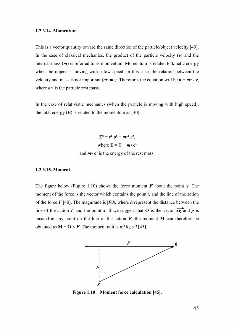
Table 1.1 Types of mechanical testing machine 53
Table 3.1 The adult human enamel thickness of the second molar 86
Table 3.2 The second premolar enamel thickness in millimetres 87
Table 5.1 Results of independent sample t-test comparing the means 106
(SD) of dislodgment resistance between the conventional
three-unit FPD and the new FPD’s design
Table 5.2 Statistical significance between the two tested groups 107

6
List of figures
Figure Pg
Figure 1.1 Complete denture in and out of the patient mouth 18
Figure 1.2 Conventional bridge 19
Figure 1.3 Single crown 19
Figure 1.4 Implant 19
Figure 1.5 Removable partial dentures in and out of the patient mouth 20
Figure 1.6 Analytical description of Vector 40
Figure 1.7 Vectors with the same directions and magnitude 41
Figure 1.8 Vectors with the same length and opposite direction 41
Figure 1.9 Multiple vectors calculation 41
Figure 1.10 Moment force calculation 45
Figure 1.11 The change in a spring original length 47
Figure 1.12 Relationship between stress and strain (Proportional limit) 49
Figure 1.13 Poisson ratio 50
Figure 1.14 Type of loads 52
Figure 1.15 Three-Point Bending Diagram 52
Figure 1.16 Human tooth structure 56
Figure 1.17 The centre of resistance to movement in the tooth 57
Figure 3.1 Image of the original design pontic 71
Figure 3.2 Image of the Original design components 72
Figure 3.3 Image of five components of the original design fixed together 72
Figure 3.4 Image of vertical View of the Major Part 74
Figure 3.5 Image of vertical View of the Minor Part 74
Figure 3.6 Image of vertical view of second model major part 76
Figure 3.7 Image of side view of second model major part 76
Figure 3.8 Image of vertical view of second model minor part 76
Figure 3.9 Image of vertical view of the second model 77
Figure 3.10 Image of horizontal view of the second model 77
Figure 3.11 Image of the second model major part 78
Figure 3.12 Image of the second model (Major and minor part) 79

7
Figure 3.13 Image of the second model wax patter 79
Figure 3.14 Image of distal view of the final design (new FPD design) 81
Figure 3.15 Image of the new FPD design attached to abutment teeth 81
Figure 3.16 Horizontal view of the major and minor parts 82
Figure 3.17 Buccal (Horizontal) view of the New FPD design 82
Figure 3.18 The location of the measured area of the suctioned teeth 85
Figure 3.19 Electronic caliper (SPS, 432-025, Mitutoyo) 86
Figure 3.20 Horizontal View from the distal side of the tooth showing
the suggested Preparation 88
Figure 4.1 Image of the hollow rectangular prism-shaped base 92
Figure 4.2 Image of premolar and molar teeth positioned in the mould 93
Figure 4.3 Buccal view of the abutment teeth preparations (new design) 95
Figure 4.4 Mesial view of the abutment teeth preparations (new design) 95
Figure 4.5 Image of The major and minor parts after the wax-pattern cast 102
Figure 4.6 Horizontal view of the new FPD design after the wax-pattern cast 102
Figure 4.7 Conventional three-unit FPD specimen after the wax-pattern cast 102
Figure 4.8 Zwick/Roell Z020 universal testing machine 103
Figure 8.1 Stud Snap attachments 120

8
Abstract
Introduction: Various improvements have been accomplished in order to provide a
better solution for the restoration of missing teeth, but with limited success. Fixed
bridges have been considered one of the most effective dental treatments for partially
edentulous patients; however, a major disadvantage of fixed bridges is the aggressive
reduction of the healthy natural abutment teeth. Another disadvantage of dental
bridges is associated with the use of dental cements as they have issues regarding their
relatively low strength and varying level of solubility. Accordingly, a new fixed
bridge that is conservative for the abutment teeth and retained without using any
cement was introduced in this study. Aims: The aim of this study is to produce a new
fixed partial denture design with minimum abutment teeth reduction. The purpose of
this in vitro study was to evaluate the maximum tensile force required to dislodge the
conventional three-unit fixed partial denture, and to accordingly compare it with a
new fixed bridge design. The obtained new bridge design should be fixed using
mechanical force rather than chemical force. It has four clasps, each of which will be
engaged into the prepared abutment teeth. Materials and Methods: Forty (40)
extracted human teeth (20 second premolar, 20 second molars) were collected. A
three-unit bridge case was then simulated by mounting one second premolar and one
second molar in acrylic resin blocks, leaving the space of the first molar missing.
Twenty (20) acrylic blocks were constructed and divided into two groups (n = 10).
Teeth preparations were preformed according to each group criteria and with the
objective to restore the missing first molar. Following, the prostheses were fabricated
and casting was made in cobalt-chromium alloy. The metal frameworks on the first
group (conventional three-unit FPDs) were cemented with zinc phosphate cement,
and metal frameworks on the second group (new FPD designs) were fixed directly to
the prepared teeth without the use of any cement. The specimens were then subjected
to tensile loading at a cross-head speed of 0.5 mm/min in a universal testing machine.
The mean separation forces in Newtons were recorded and statistically analysed with
the application of a one-way analysis of variance (ANOVA). Results: The mean (SD)
value of the maximum tensile force required for dislodging the conventional three-
unit FPD frameworks were 170.97N (21.09) and for the new FPD framework were
387.80N (22.21). Conclusion: The conventional three-unit FPDs group showed a
significantly lower mean dislodgment resistance compared with the new FPD designs
group (P < 0.001). The current study indicates that the new suggested FPD can be
clinically viable design in terms of mechanical retention, however, further clinical
research need to be conducted.

9
Declaration
No portion of the work referred to in this dissertation has been submitted in support of
an application for another degree or qualification, of this or any other university or
other institute of learning.

10
Copyright Statement
i. The author of this thesis (including any appendices and/or schedules to this thesis)
owns certain copyright or related rights in it (the “Copyright”) and s/he has given The
University of Manchester certain rights to use such Copyright, including for
administrative purposes.
ii. Copies of this thesis, either in full or in extracts and whether in hard or electronic
copy, may be made only in accordance with the Copyright, Designs and Patents Act
1988 (as amended) and regulations issued under it or, where appropriate, in
accordance with licensing agreements which the University has from time to time.
This page must form part of any such copies made.
iii. The ownership of certain Copyright, patents, designs, trade marks and other
intellectual property (the “Intellectual Property”) and any reproductions of copyright
works in the thesis, for example graphs and tables (“Reproductions”), which may be
described in this thesis, may not be owned by the author and may be owned by third
parties. Such Intellectual Property and Reproductions cannot and must not be made
available for use without the prior written permission of the owner(s) of the relevant
Intellectual Property and/or Reproductions.

11
Acknowledgments
I would like to express my gratitude to Professor David Watts and Dr. Nick Silikas for
their help and support during this study.
I would like to thank Dr. Iain Pretty for his cooperation.
I would like to thank Mr. Brian Daber for his assistance.
I would also like to thank Mrs. Rose-Marie Parr for her appreciated help and advice.

12
Dedication
TO MY MOTHER
TO MY BIG BROTHER
MOHAMMED
TO MY FAMILY

13
Chapter 1
Introduction
and Literature Review

14
1. Introduction and Literature Review
The first chapter consist of two main parts. It will be structured as follows; firstly, it
will provide a literature review of dentistry; secondly, a literature review on
mechanics will be mentioned highlighting the most important topics of each part.
1.1. Dentistry
1.1.1. Introduction
Since the beginning of time, human beings have continuously strived to improve their
lifestyles in various different ways. Dentistry is and has always been one of those
important fields which help people to eliminate their oral pain, be able to eat properly
and to look good, improving levels of confidence in many essential life areas.
For a long period of time, scientists, dentists and dental technologists have tried to
improve the construction and anchor of dental appliances. Nowadays, those
improvements have helped to develop both the tooth’s function and appearance.
Missing teeth is a common problem now affecting many people, especially those who
are over 40 years old [1]. Circumstances vary from patient to patient, they might
become edentulous (completely without teeth) especially the elderly people, or they
may lost just some of their teeth. For each case, there are various ways for replacing
the real teeth with artificial teeth by using different techniques. In the following
paragraphs, we will discuss the methods for restoring the missing teeth, types of
dentures, and we will also provide an overview for each one of main techniques.
1.1.2. History
The first attempt of replacing a missing tooth was made by people in north Italy in
about 700BC. They started to make dentures from other human beings’ teeth or from
animals’ teeth. This technique was famous and widely adopted until around 1950 [2].
The first denture sets were made out of curved wood in the 15th
Century, although it
could possible have been made even earlier. The idea at that time was to remove the
15
teeth of dead people or to get them from living people who wanted to sell or exchange
them. These dentures were, as can be expected, incredibly uncomfortable, and could
be easily seen and did not provide cosmetic benefits. Contrary to the sophisticated
techniques adopted nowadays, the old-fashioned dentures were held in place by
attaching the denture to the natural remaining teeth with either metal or silk [2].
In 1770, Alexis Duchateau made the first porcelain denture around 1770. Then, in
1791, his British assistant Nicholas Dubois made a big improvement to the fabrication
of porcelain dentures; he created a composition for making single or multiple teeth as
one unit, and discovered new, more successful ways of joining them together and
making them better able to fit. More recently, there are different kinds of materials
available, such as acrylic resin and plastic, and a variety of systems have now been
developed to assisting dentists, dental technologists and patients with getting better
results and porcelain is still one of them [3].
1.1.3. Basic considerations
Generally, the chosen method depends on several factors. Some of these factors relate
to the patient, while others relate to clinical and laboratory reasons. The following
points provide some reasons and circumstances which could subsequently affect the
chosen method implemented for tooth replacement:
1. How many units need to be replaced with artificial teeth? [4].
2. The location of the missing teeth/tooth (upper, lower, anterior, posterior, etc.);
this is a very important consideration, especially if the patient has anterior
missing teeth. In this case, the dentist would normally give the patient the
choice of between the available options with the best aesthetic appearance.
3. The condition of the neighbouring tooth/teeth. For example, crooked tooth,
caries and unstable abutments affect the stability of the denture, especially
with some different types of the fixed bridge, such as the Maryland fixed
bridge [1].
4. Patient oral and overall health can also affect the treatment method. For
example, when the patient is very old, implants might not be a good option for

16
him/her as the implant post (screw shape) need to be inserted into the jaw bone.
In addition, in some cases, patient’s overall health conditions might not help
him/her to do such surgery [4].
5. Although implants is one of the best ways to fill the gap of the missing
teeth/tooth, a lot of patients are not in a position to be able to afford this
treatment as it is so expensive compared to the other available options, such as
fixed and removable dentures. Therefore, in some cases the treatment plan
could be changed due to financial reasons.
1.1.4. Circumstances of teeth lost
There are many cases where individuals lose some of their teeth while, in other cases,
they may lose all of their teeth. Dentists used to extract the tooth if the tooth was
considered to be non-restorable [4]. Also, accidents and hard impacts on the tooth
may cause tooth loss. In addition, some people may not have had some of their teeth
since birth [4]. While some patients have one or more teeth growing in the wrong
place over the jaw (externally or internally). In each one of these cases, the
replacement of the missing teeth with artificial teeth is required in order to improve
the appearance and the function of the teeth.
1.1.5. Possible problems occurring from injured or lost teeth
The loss of a single tooth or multiple teeth can affect the person appearance and/or
health, while ultimately affects levels of confidence and overall life happiness. Losing
the anterior teeth (front teeth) affects the way a patient talks and smiles, and that
might subsequently make the patient avoid going out in public due to social
embarrassment. If the person has lost one (or more) of the posterior teeth (back teeth),
the patient will not be able to eat properly, and this might affect his overall health [5].
After a period of time, the gap of the missing teeth is going to allow the movement of
neighbouring teeth, which will result in the patient needing orthodontic treatment [12].
Teeth support the lips and cheeks, and missing one or more teeth impinges the way
the face looks [1]. Impacts, such as falling on the teeth, may also cause dental

17
problems and severe pain. Even if the tooth or teeth have not come out entirely, they
might nevertheless allow the bacteria to grow and cause severe pain, especially for
immature permanent teeth; in this instance, it is highly recommended that the injured
or missing teeth are treated or replaced as soon as possible [7].
1.1.6. Ways of restoring missing teeth
The field of dentistry has different opportunities for restoring lost teeth. After the
dentist sees the condition of the patient’s teeth he might agree with the patient to do
one of the following treatment plans [4]:
Fixed Partial Denture (FPD)
Removable Partial Denture (RPD)
Complete Denture.
Interim Partial Denture (Flipper)
Implants Restoration
Maryland Bridge (Resin Retained Bridge)
Cantilever Bridge
1.1.7. Types of denture
There are two main types of dentures: complete dentures and partial dentures. Each
one of these types has its own requirements and technique. In the following points, we
will discuss each one of these individually.
Complete dentures are used only with edentulous patients (with out teeth). The
dentures cover the entire jaw and can be applied in the upper jaw, lower jaw or both
(the maxillary or mandibular arch). It consists of artificial teeth attached to a base
made of acrylic raison (Figure 1.1), and is ideally held in place by one of mediums:
suction of the saliva or by attaching the denture to implants [4, 8].

18
Figure 1.1 Complete denture in and out of the patient mouth [9].
Partial dentures are divided into two types: fixed partial dentures and removable
partial dentures.
Fixed partial dentures are better known as ‘crown and bridge’ (Figure 1.2 and Figure
1.3). Bridges usually consist of one or more abutment (neighbouring teeth/tooth) and
one or more pontic (the artificial tooth which is placed in the edentulous area). The
fixed bridge always requires preparation of the neighbouring teeth/tooth. The reshape
of the neighbouring tooth presents the space for the fabricated artificial abutments to
be fitted over the natural teeth/tooth perfectly, and obtain retention which increases
the bridge’s stability in the mouth. Before the fixed denture is positioned over the
shaped neighbouring teeth/tooth, the retention of the denture is supported by applying
suitable cement between the artificial unit and natural teeth/tooth [10].
Types of fixed bridges are classified according to the number of the abutments [11].
When the bridge has one abutment and is supported from one end, it is called
cantilever bridge, but if it has two abutments it is called a conventional fixed bridge
(Figure 1.2). In some cases, where patient has a lot of caries all over the tooth, the
dentist will remove most of the natural tooth. The tooth can be fully covered with an
artificial tooth called single crown (Figure 1.3) [12]. Fixed bridges and single crowns
can be made of different kind of materials such as: gold, cobalt-chromium alloys,
nickel-chromium alloys or porcelain, or even a combination of more than one of those
materials. When patients have the choice, they often prefer to cover the prosthesis
with ceramic (porcelain) in order to improve the appearance of the teeth/tooth.
19
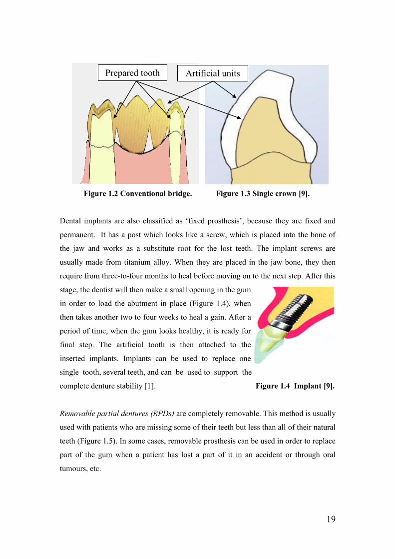
Figure 1.2 Conventional bridge. Figure 1.3 Single crown [9].
Dental implants are also classified as ‘fixed prosthesis’, because they are fixed and
permanent. It has a post which looks like a screw, which is placed into the bone of
the jaw and works as a substitute root for the lost teeth. The implant screws are
usually made from titanium alloy. When they are placed in the jaw bone, they then
require from three-to-four months to heal before moving on to the next step. After this
stage, the dentist will then make a small opening in the gum
in order to load the abutment in place (Figure 1.4), when
then takes another two to four weeks to heal a gain. After a
period of time, when the gum looks healthy, it is ready for
final step. The artificial tooth is then attached to the
inserted implants. Implants can be used to replace one
single tooth, several teeth, and can be used to support the
complete denture stability [1]. Figure 1.4 Implant [9].
Removable partial dentures (RPDs) are completely removable. This method is usually
used with patients who are missing some of their teeth but less than all of their natural
teeth (Figure 1.5). In some cases, removable prosthesis can be used in order to replace
part of the gum when a patient has lost a part of it in an accident or through oral
tumours, etc.
Prepared tooth Artificial units

20
Similar to the complete dentures, RPDs consist of artificial teeth/tooth and a gum-
coloured plastic base (Figure 1.5) [12]. Each of the parts of the denture is joined
together with a metal framework called the ‘major connecter’. The major connecter
could be scientifically described as a maxillary palatal metal bar/plate and lingual bar
or plate. It provides retention to the denture with the support of clasps which are
attached to the natural teeth.
Figure 1.5 Removable partial dentures in and out of the patient mouth [9].
1.1.8. Advantages and disadvantages of dental prosthesis
Advantages of removable partial dentures [4]:
Not that much more expensive when compared with the other dentures.
The acrylic resin of the removable denture looks similar to the natural soft
tissue of the jaw. When a big part of the bone is lost, the acrylic resin is
designated in order to improve the appearance of the jaw.
When the patient has trouble with hygiene, the RPD will help to overcome this
issue.
Disadvantages of removable partial dentures:
Require a big amount of metal framework to restore one or two teeth.
Very sensitive and breakable and, therefore, it needs special care if the
patient wants to remove it from of mouth.

21
Advantages of Conventional Bridges (fixed partial dentures) [4]:
Very good appearance.
It is fixed in the mouth (not removable) and lasts longer than the RPD. In
addition, it makes the patient feel like he/she has permanent teeth.
It evenly distributes the chowing forces.
Disadvantages of Conventional Bridges (fixed partial dentures):
It is necessary to prepare the abutments in order to fix the artificial teeth.
Usually, the neighbouring tooth preparation leads to destroying the anatomy of
natural and healthy teeth since it requires a significant reduction.
The prepared teeth (abutments) are at risk of recurrent caries [13].
Expensive to remake if a replacement is required for any reason.
The unnatural appearance of the denture (between the bridge and gum).
Very accurate fabrication required.
Advantages of Transitional Partial Denture or Flipper [4]:
Good natural look, and restores the missing teeth function.
Flippers could also be a temporary solution during the healing of the implant
opening in the jaw.
Reasonably priced.
If the patient does not want to have a lot of appointments, or did not want to
stay at the dental clinic for a long time, the Transitional Partial Denture would
then be a suitable choice.
Disadvantages of Transitional Partial Denture or Flipper:
Flippers have no rest seat and so the denture pressure over the soft tissue
might cause tissue problems after a long period of time.

22
The material which is used to fabricate the T.P.D. is able to absorb the saliva
and it can then be easily cracked or broken.
Advantages of Maryland Bridge (fixed partial dentures) [4]:
The idea of the Maryland Bridge fabrication is similar to the fixed partial
denture, but with less neighbour teeth preparation (little shaving from the
labial side of the teeth).
Option for the youthful patient rather than the FPD.
Instead of implant crowns, Maryland bridges are recommended if the patient is
not fully grown.
Disadvantages of Maryland Bridge (fixed partial dentures) [1]:
Failure of the bonding between the denture wings (metal abutments) and the
natural teeth.
The metal wings of the denture might make the abutment teeth look darker.
The aesthetic of the Maryland Bridges is not as much as with the implants.
Maryland Bridge is not be applicable if the patient have a big caries in the
abutment tooth.
Patients are not advised to use a toothpick or bite any hard objects.
In 1990, a five years study was conducted to evaluate the survival rate of resin-
bonded bridges. The authors reported that, among 203 patients, 77 cases had deboned
due to dislodgment or pontic fracture. Also, they conclude that there was no
relationship between the bridges failure and the used cement or the retainer type [14].
Although the Resin-Retained Fixed Partial Denture (Maryland Bridge) is one of the
cheapest and most useful ways of restoring missing teeth, it unfortunately, has a
massive number of reported failures between 10% over eleven years and 54% over 11
months. Unlike with the fixed partial denture, the Maryland Bridge is not appropriate
for patients who have crooked abutments [1].

23
Advantages of Cantilever Bridges (fixed partial denture) [4]:
The Cantilever Bridge uses only one abutment as a retainer. This technique
saves the tooth structure (anatomy) as much as possible, especially if we
compare it to the conventional fixed bridge.
Least expensive.
Disadvantages of Cantilever Bridges (fixed partial denture) [13]:
It could not evenly spread the forces properly because it is fixed only in one
abutment. This kind of bridge may affect the natural abutment of teeth
stability and cause teeth dislodgment.
Unlike the implants, the Cantilever Bridge requires tooth preparation for the
abutment tooth. This significant tooth reduction of the abutment is considered
to be a major shortcoming as previously mentioned.
Advantages of Implants:
Do not affect the neighbouring teeth in any ways as it directly connects the
artificial tooth to the jaw bone.
Implants provide high stability, so that it can be used as a retainer to fixed
dentures (fixed bridges) or complete dentures.
It protects the bone by filling the gap of the natural bone.
The best aesthetic of kinds of dental prosthesis.
No preparation of the abutment teeth is required.
Disadvantages of Implants [4]:
Patient must have more then one surgery
There should be a long-term treatment plan extend to several months.
After the first surgery, the dentist cannot proceed with the treatment plan as
the surgery opening needs to heal completely (time consuming).
Temporarily prosthesis is required.
24
Unnatural appearance between the artificial tooth/teeth and gum.
Patients who want to have a fixed implant must not be extremely ill or have
any kind of disease which may prevent him/her from having the implants. The
patient jaw bone should be in a good condition because there should be
available bone for the screw to fix into it. Moreover, pregnant women can not
have implant surgery. As such, the patient health condition must be clarified
before the dentist can take any decisions.
There are a number of cases where patients are able to use implants instead of the
other types of prosthesis. For a long time, dental implants have proved that they can
work perfectly. When the patient cannot wear the removable denture (complete
denture), dental implants can then solve that problem by fixing more than one implant
to the upper or lower jaw bone [1]. The fixed implants can then provide enough
stability to hold the denture in place. In addition, it might be used as an alternative to
the fixed partial denture (fixed bridge) if the patient does not feel comfortable with the
fixed denture. Also, implants could be use if the patient is not happy with the
abutments proportion, especially when the abutment teeth are healthy and in good
shape.
Implants are very useful if the edentulous area is very large, and the fixed denture
needs extra support. Sometimes, patients do not have a fixed partial denture
(cantilever or conventional bridge) because there are more than four missing teeth
beside each other (in a row), which makes it too difficult for the denture to remain
stable over the abutments as they are simply too faraway from each other [1].
Depending on the patient case, the dentist can use one implant or more (in the
edentulous area) in order to increase the denture stability.
1.1.9. What are fixed partial dentures made from?
Most patients prefer to replace their missing teeth with artificial PFM (Porcelain
Fused to Metal) as it looks more like the natural teeth, while some patients still prefer
metal or gold prosthesis rather than the porcelain teeth. However, the majority of
people prefer to have artificial teeth which are natural looking. Ideally, the porcelain

25
tooth consists of a combination of porcelain fused to metal, if the missing tooth is
posterior (in the back), and full porcelain if the missing tooth is anterior (in the front).
The combination of artificial teeth have more strength than the porcelain teeth, which
makes the denture stronger, providing it with better resistance with regards to the
chewing force. On the anterior teeth, the chewing load is less than the posterior teeth,
which is aesthetically better for placing full porcelain dentures over missing
teeth/tooth. All-metal fixed dentures are the strongest dentures since they do not break
under the chewing pressure. Although PFM is also strong, but it is not considered to
be as strong as full-metal prosthesis. All-gold crowns are also one of the best
materials for use in dental-fixed dentures, unless they are considered to be more
expensive than the other available materials [9].
Generally, casting alloys are divided into two main types. The first type is known as
noble alloys, where the second type is known as based metal alloys. The majority of
the noble alloys are gold- and palladium-based materials, and the based metal alloys
are nickel- and cobalt based materials [11]. The used materials in fabricating FPD are
varying. However, some based metals such as cobalt-chromium alloys have been used
widely, as they are cheaper than most of the other available material and perform
acceptably [15].
1.1.10. Steps to clinically preparing the FPD
Before the treatment initiates, the dentist first examines the situation of the patient to
determine if the fixed partial denture is necessary as well as carrying out an X-ray
examination. If the dentist agrees with the patient that he or she really does require
fixed prosthesis, the dentist will then begin the first steps of the fixed crown or bridge.
After the agreement of applying the fixed partial denture, the dentist then has to start
preparing the abutment teeth/tooth. During the patient’s first visit, the dentist will
reshape the tooth/teeth in such a way which allows the denture to be placed over the
natural tooth/teeth. Normally, there are standard circumstances for the fixed partial
denture preparation by making a reduction on all around the tooth/teeth; this reduction

26
will create the required space for the new prosthesis to be positioned over the
prepared units.
When the reduction is complete, the tooth/teeth must then be tapered into shape. If
there is any undercut on the surface of the tooth, the restoration will not be able to be
removed from the die. The prepared units require specific measurements of two to
three degree of taper [12]. Clinically, there are special instruments to aid the dentist to
getting that specific degree, and allows the fixed bridge or crown to be placed
properly in the mouth. It is also important to note that if the tooth has been tapered too
much it will affect the restoration stability as there will not be enough retention for the
denture to be held into place. That means, a six-degree of taper all around the tooth is
needed in order to give a total of twelve degrees of taper; any more than this could
negatively affect the stability of the denture [12].
During the tooth preparation process, it is also important to make the margin ideal.
The margin can be described as the line which is present around the tooth at the
junction between the artificial tooth and the natural tooth. The fixed denture cannot
survive without a good margin, and even if the artificial tooth is perfectly constructed,
it will still not last for a long time if the margin experiences any problems. The
margin must be smooth and strictly adapted to the finish line. If there is an opening in
the margin it will affect the denture stability [16]; moreover, it will also allow food to
stick in the openings, which can ultimately lead to poor oral health. The margin is
normally located between the natural tooth and the artificial tooth, and so it might be
seen when the restoration is in the posterior area; in that case, dentists always try to
take care when they draw the margin simply because it must work sufficiently and not
be too visible to the naked eye [12].
There are different kinds of margins, which each depend on preparation. The first type
of margins is called a ‘chamfer’. This margin type is very popular with full gold
prosthesis. It provides the best strength which the crown/bridge needing to be adapted
perfectly, and is very effective in removing a very small amount of the tooth structure,
which allows the dentist to work with the smallest detail. The second type of margin
is called the ‘shoulder margin’. This particular margin is popular with the PFM

27
(Porcelain Fused to Metal) prosthesis, and it is also useful when preparing the tooth
for all-ceramic restorations [16].
After the tooth preparation, an impression of the tooth/teeth is taken and sent to the
dental laboratory in order to fabricate the artificial prosthesis. Because of the
improvement of the dental technology, there are many different ways of fabricating
the dental crowns/bridges.
1.1.11. FPD fabrication procedure in the laboratory
The chosen method of fabrication purely depends of the type of material used with the
restoration, for example, whether it is full ceramic, full metal or Porcelain Fused to
Metal. When the dental laboratory receives the impression, the dental technician
pours and mounts the cast by using different types of dental stone or plaster [12], and
when the stone model has dried when the thermal heat disappears the cast is then
ditched and trimmed into the required shape. After this stage, the pins are then
cemented to the bottom of the cast and another mixture is made in order to mount the
base of the cast and attach it to the articulator, which is a device used to attached the
upper (maxillary) and lower (mandibular) casts. The articulator provides the link
between the upper and lower jaw, as it is in the patient’s mouth which ultimately
allows the dental technologist to see how the upper and lower jaw meet with each
other and subsequently aids him/her to properly fabricate the tooth to do its function.
From this stage, the casts are then taken out of the articulator before they split the cast
from the base and split the prepared teeth/tooth from the rest of the cast into
individual dies by using a saw [12]. The finished line of every single die (of the
prepared tooth) is then exposed using the wax knife and the teeth/tooth fabrication is
made using one of the following techniques:
1.1.11.1 All-Wax technique
The all-wax technique is used when the denture if made completely from metal. There
are different materials which could be used in the full metal restoration, and gold is
one of the best kinds of material. The gold alloys consist of various different elements,

28
such as gold, palladium, platinum (noble materials), tin, silver and copper (based
materials). Although the full gold prosthesis does not look good cosmetically, they do
nevertheless have the advantage of being very good quality, as they are considered as
high-noble materials, according to the American Dental Association because it
contains 75% noble metal [11]. Full metal dentures irrespective of whether it is gold
or any other suitable dental material are manufactured with the implementation of a
technique called the ‘lost wax technique’. In order to get the final shape by using the
lost wax technique, the artificial teeth must first undergo many more stages before
getting the final result.
Firstly, a die spacer should be applied over the die/dies in order to provide the space
between the artificial teeth/tooth and the prepared tooth. This thin space will allow
place for the cementation which will be applied clinically before fixing the denture in
the patient’s mouth [12]. After this stage, a die lubricant must then be applied so that
the wax pattern can be easily removed the die lubricant prevents the wax pattern from
sticking to the die after the wax build-up is completed.
Secondly, the dental technologist will then start to build-up the wax pattern by coping
the die. The coping procedure is focused on creating a thin layer of wax over the die.
Normally, the coping is made from wax but it is also possible to make the coping
from a heated resin sheet [12]. After this stage, the wax is then applied over the
coping layer be using a hot wax spatula. Some other instruments might also be used,
for example, a wax knife and wax carver, in order to build-up the wax pattern. At
some point, the die should be returned to the cast (which is fixed to the articulator) in
order to manipulate the wax until the wax pattern appears to be similar to the
dimensions of the original tooth, and does not interfere with the opposing teeth (in the
opposing jaw).
Thirdly, when the wax tooth/teeth appear to be in a good shape (final shape) the wax
pattern is then removed from the die and attached to a special kind of wax stick called
a ‘sprue former’, which is a small diameter tube usually mad of wax; the ideal tube
width used with crown/bridge is 2.6 mm [12]. The sprue is attached to the wax pattern
from one end, while the other end is attached to a conical rubber base. The sprue with
the wax pattern is inserted into a special ring while the rubber base works as a base to

29
that ring. After this stage, the investment material is then mixed and poured into the
ring. When the investment material has completely set, the rubber ring is then
removed, and the base will then form a crucible shape with a hollow in the middle.
This funnel-shape will force the metal to go into the mould during the casting
procedure while the hole in the middle of the ring will allow the molten wax to get out
the mould. It is highly recommended that the sprue is attached with its angle to the
bulkiest area of the wax pattern. Attaching the sprue in angle with the wax pattern will
allow the molten metal to flow into the mould easily [17]. It is also important to
consider that the wax pattern should be 6 mm away from the end of the ring; if it is
too close to the end of the ring, the molten metal might blast through the investment
material and, if it is too far from the end of the ring, that may disallow the gases from
escaping from the mould during the casting [12].
Fourthly, the investment ring is placed upside down in an oven at a temperature of
600F for thirty minutes [12]. During that stage, the wax will burn out from the mould.
At this point, the temperature should then be increased up to 1,200F for one more
hour, after which the ring is then removed from the oven and placed into the casting
machine (the casting temperature is vary depending on the type of the metal alloy)
[18]. It is very important to note that when the investment ring is removed from the
oven, the molten metal should be permitted to flow into the mould within thirty
seconds because if the ring loses the heat, the mould will then contract and the
dimensions of the mould will changed [17]. After placing the ring in the cast machine,
a sufficient amount of metal is then placed into the machine whereupon the casting
will begin. The metal will be quickly melted and then shot through the opening into
the mould. The metal will take the same shape and dimensions of the disappeared wax,
which is then called the Lost Wax technique.
At this point, the ring is finally removed from the casting machine and placed at room
temperature until it is properly cooled. Then, the ring is de-invested and the
crown/bridge is separated from the sprue, which can then be recycled. The
crown/bridge is then finished and polished until it shines before it is sent to the dentist
to try in the patient’s mouth during the second appointment. Little adjustment might
be applied upon the final cementation.

30
Porcelain Fused to Metal is made similarly, except that after the coping procedure, the
wax pattern is not waxed up completely; instead, it just needs to have a suitable wax
adjustment, which allows the porcelain to be built up over the metal (after
transforming the wax into metal with same steps).
1.1.11.2. Empress
The Empress technique uses the same basic idea and principle of the lost wax
technique, only there is a hole in the investment ring. The empress system works in a
slightly different way as it has a special design, which is the pressure injection. The
main principle of this particular system involves leucite-reinforced ceramic,
whereupon the ceramic is pressed into the mould of the artificial tooth in a unique
pressable porcelain oven [19]. This machine does the work of both the oven and the
casting machine together, which means the restoration is melted then pressed into the
mould at the same time. In addition, the Empress machine can do any job the lost wax
may require. It can also make any prosthesis for the all-ceramic restoration, such as,
single crowns and laminated veneers, which is made only from ceramic and did not
have any metals [12].
1.1.11.3. In-Ceram
In-ceram has been introduced by Vita; it is also one of the famous systems which has
been used in full ceramic restoration [12, 19]. Unfortunately, all-ceramic crown
prosthesis requires too much tooth removal. For in-ceram, the tooth preparation must
be 1.5mm arterially and from 1.5mm to 2mm from the occlusal side; although the all-
ceramic restoration has the best tooth appearance, it still needs a significant amount of
tooth reduction, which most of people consider being a negative thing [12].
1.1.11.4. Procera
Procera is a computer aided milling system (software) which is used to fabricate free
metal restorations. It is CAD/CAM method and, generally, it has it is own technique
which depends on constructing the artificial prosthesis with Vitadur Alpha porcelain,
by overlaying a very strong ceramic coping made of zirconium or alumina referred to

31
as the ‘core’ [12]. Lately, Procera has been improved widely by being able to produce
various kinds of dental restorations, such as veneers, crowns and bridges.
1.1.12. Investment
In order to produce cast metal devices, the investment material is poured over the wax
pattern (in the investing ring) and placed into the oven. After the wax melts and runs
out, the exact negative of the original model is formed [18]. The investment ring is
then casted, and the metal prosthesis is produced.
The process of investing the common types of dental prostheses (such as crowns,
bridges or partial denture frameworks) involves common types of investment
materials, such as [20]:
1.1.12.1. Gypsum-bonded investments
Gypsum-bonded casting investment is usually used for the purpose of casting metal
alloys which have low fusion temperature [21]. Two main techniques (described by B
W Darvell [18]) can be used to control mould expansion of this type of materials,
those techniques are:
A – Large expansion can be obtained by heating the mould to 700°C.
B – Hygroscopic expansion can be obtained by heating only to 500°C.
It is appropriate to cast gold-based alloys by using gypsum-bonded investments, and
heat it up to 700°C, because the fusion temperatures of the metal alloys to be cast
within it are relatively low [22]. Furthermore, using high-fusing metal alloys, such as
cobalt-chromium, with this kind of investment material might result in various
consequences, such as incomplete casting, as the cobalt-chromium alloys melting
point goes up to 1,500°C [18, 22]. As such, it is therefore advisable to avoid casting
high fusion temperature alloys by using any gypsum products [18].

32
1.1.12.2. Phosphate-bonded investments
This type of investment is bonded by a magnesium oxide and a phosphate [18]. The
chemical properties of the phosphate-bonded investments make it a suitable option for
high-fusing alloy casting [23]. It is commonly used to cast cobalt-chromium alloys
[18, 20, 23].
The reactions between the phosphate-bonded investment crystals continues to react
beyond 1,000°C, which subsequently helps to more accurately control the amount of
mould expansion [18]. However, although there are different products of investment
materials which could be use for casting metal alloys, it is always better to use
phosphate-bonded investments to cast metals which have a melting point ranging
between 1,200 and 1,450°C [18].
1.1.12.3. Silica-bonded investment
Similarly, this type of investment is used with alloys which require a higher
temperature (high-melting point) for the investment mould [24]. The temperature of
the mould in this type of investment reaches up to 1,200°C, and larger expansion will
occur during heating [18]. However, although there are some disadvantages of using
this type of investment (such as the possibility to crack at the casting temperature),
this option nevertheless still provides very accurate detail of the original melted wax,
which ultimately makes using the silica-bonded investment become more useful in
some cases, particularly when compared with phosphate-bonded investments (as
along as each one of them is used for high fusion alloys) [18].
In some cases, special types of investment material which have particular chemical
properties are recommended in order to control shrinkage and to therefore make the
casting procedure even more accurate whilst reducing the chance of any changes
occurring in the original dimension of the wax pattern [25].
There are some laboratorial factors which can affect the dimensional accuracy of the
cast metal, the most important of which include the investment setting material
expansion and investment expansion on heating [18]. Accordingly, the dimension of

33
the original wax pattern might change slightly (if phosphate-bonded investments or
gypsum-bonded investments are used). Researchers have improved the chemical
properties of the investment materials in order to provide accurate casting until they
were able to devise the High Speed Investment Material (such as, Microstar HS,
Ceramay and SC High Speed Investment Material). Using this type of investment
helped to provide an exact reproduction of the wax pattern surface [26].
In conclusion, the total expansion can be perfectly controlled and a very exact
reproduction of the original wax pattern can be obtained using High Speed Investment
Material. This procedure will therefore avoid any expected gaps and help to obtain
more accurate fit, therefore increasing overall denture stability.
1.1.13. Remaining problems even with the new generation of the
fixed partial dentures (crown and bridge)
Commonly, there have been a few experienced problems with each type of dental
prosthesis. During the past few years, there have been significant improvements in the
construction of dental appliances; some of these changes were clinical changes while
some were laboratory changes. Mainly, the improvement was concentrated on one of
the following two fields, or in both of them together:
The material which has been used in the field of dentistry;
The technique of fabricating the tooth restoration.
One of the main problems with fixed partial dentures is that they require a significant
amount of preparation on the abutment tooth (neighbouring teeth/tooth) [4]. Usually,
destroying virgin teeth comes about as a result of irreversible preparation, and so
patients nearly always prefer to have implants rather than the fixed partial dentures,
unless they are not as cheap as the fixed bridges, which makes it an unacceptable
option for most people.
Another problem with crowns and bridges is that it is could encounter caries after a
while [13]. The decay occurs as the abutment tooth/teeth is/are fully covered with

34
artificial crowns/bridge. After the prosthesis is cemented over the treated tooth/teeth,
it is very difficult to be removed again [10], and a piece of the natural tooth can
sometimes come out when the dentist tries to remove the restoration. In this situation,
the prepared tooth/teeth cannot be cleaned (brushed) as long as the denture is placed
over it, and, subsequently, more problems will present themselves internally (at the
surface between the natural tooth and the artificial tooth).
Moreover, if the prosthesis needs to be completely replaced, it will be very expensive
[4]. If the crown/bridge falls down and the denture requires adjustment, a new denture
should be fabricated again, as neither the dentist nor the dental technologist will be
capable of adjusting the old artificial unit.
1.1.14. Previous studies, and FPD development
There was a large expansion in solving the troubles associated with restoring missing
tooth. Until this moment, a lot of disadvantage have appeared, even with the latest
technology and techniques which have been used in this specific field of dentistry.
However, there have been many new inventions and techniques, which have proved
that there is the ability to solve some of the major problems with old designs or dental
materials by improving the used materials, such as fibres [27], methods, construction,
such as the Maryland Bridge, Computer-Aided Design and manufacturing equipment
(CAD/CAM) [12, 19]. Although, these new inventions have been being used more
recently, some of them still experience aesthetical troubles or functionality issues, but
they are nevertheless being used anyways in order to prevent some of the more major
problems.
The Maryland Bridge is one of the most famous new ways of replacing a missing
tooth. The first development took place in 1980 at the University of Maryland, which
is where it got its name [28]. The Maryland Bridge consists of single artificial tooth
attached to two metal wings on the sides. After preparing the neighbouring teeth
which requires little shaving, and only some from the inner side the wings of the
artificial tooth are bonded with appropriate cement to the back sides of the prepared

35
tooth on either side of the missing tooth [1]. This type of dental restorations is claimed
to be one of the best ways of replacing the missing teeth because it considered being
cheap, simple and conservative method. Most patients would subsequently chose to
have this type of bridges rather than the implant, conventional or cantilever-fixed
bridge, as they then do not have to pay a massive amount of cash to have an implant
or destroy the anatomy of their own natural healthy teeth (abutments).
Unfortunately, there are some aesthetic and functional problems with this kind of
bridge: Because the teeth are translucent, the metal backing the tooth is bounded onto
the back side of the front teeth, which then causes the teeth on either side to turn a
little grey; these teeth will then obviously not match in colour [4]. On the other hand,
dentists do not recommend this type of bridge to be placed in the posterior teeth
simply because it is attached to the neighbouring teeth only from one side. For this
reason, the denture will not be able to resist the applied force during mastication [1].
In addition, the Maryland Bridge is not appropriate for all patients and it does not last
forever, even with the appropriate circumstances due to teeth dislodgment. This type
of fixed bridges is not suitable if the patient has a deep bite or fractured abutment
teeth, because the denture will fail sooner or later [1]. Moreover, according to the
sensitivity of Maryland Bridges, the patient is always advised avoiding the use of
toothpicks and to not bite on tough objects.
In conclusion, the field of dentistry is always aiming to replace the lost teeth with the
best possible appearance and function. When the patient has lost one or more of
his/her natural teeth and considers restoring the missing teeth, he usually will be
looking forward to treat it without causing any more damage to the healthy teeth.
However, even with these negative points of choosing the Maryland Bridge as an
alternative treatment solution, patients still consider it to be a good choice. With this
in mind, we can understand that, as along as the applied restoration saves the natural
tooth structure (anatomy) with an good appearance, the patients will be happy to
select this option.
Since this study will present a novel fixed bridge design, there is a need to understand
the forces that applied on human teeth during mastication. The following literature
review will be helpful to detect the relation between physics/mechanics and dentistry.

36
1.2. Mechanics
1.2.1. Introduction
For a long time, people have been trying to improve their ways of life in various
different aspects. As a result, there have been developments in a vast number of areas,
including astronomy, physics, chemistry, biology, human anatomy and mathematics.
Mechanics is one of the most important aspects of physics, which describes objects’
behaviour using mathematical equations [29]. This is one of the main study areas that
has helped human beings to develop their understanding concerning the mechanisms
of objects’ movements [29, 30]. More recently, researchers have been accurately and
sufficiently analysing their experiment results in order to produce a variety of
materials with the best quality. As a result, a large number of inventions have been
revealed (such as cars, Internet, different types of drug and artificial teeth).
1.2.2. History
In the 15th
Century, there was dramatic growth in scientific knowledge, especially in
physics. Such significant improvements have been ensured by many scientists, all of
whom have played a major role in science development, such as Galileo Galilei, Isaac
Newton, Charles Darwin and Albert Einstein [31-33].
In 1546, Galileo Galilei was the first to deal with physics, mathematics and astronomy
as one subject. The studies that he carried out helped to achieve the telescope [31].
However, one of his most famous experiments in physics was dropping two balls
from the Pisa Tower, subsequently determining that the two balls reached the ground
at the same time. His work and experiments have subsequently had a major influence
on human mechanical experiences.
The English physicist, Sir Isaac Newton, had the biggest influence in the history of
science. He published his book ‘Principia’, and revealed the theory of universal
gravity, as well as the three laws of motion [34]:

37
‘Every body perseveres in its state of rest, or of uniform motion in a right line,
unless it is compelled to change that state by forces impressed thereon.
‘The alteration of motion is ever proportional to the motive force impressed;
and is made in the direction of the right line in which that force is impressed’.
‘To every action there is always opposed an equal reaction: or the mutual
actions of two bodies upon each other are always equal, and directed to
contrary parts’.
Newton describes the objects movements in terms of it velocity, acceleration and
position [35]. These laws of motion can be applied in the case of any object. He is
considered as one of the scientists who laid the foundation for the classical mechanics.
Newton’s principles are still applicable in physics at the present day.
Charles Darwin, for example, was one of the most remarkable physicists during this
period, and scientists would refer to him as the father of science, simply because of
his success in physics field [33]. Furthermore, Maxwell’s electromagnetic theory was
a very important and remarkable step, which gives other scientists the opportunity to
discover the modern physics world [37].
Following Newton’s steps, Albert Einstein, explains gravity and its laws more
sufficiently. His new ideas and thoughts have played a significant role in changing the
classical mechanics into new physics generation [37]. His achievements began when
he first attempted to understand the reasons behind the speed of light being constant
[38]. Einstein’s theory of relativity was and is considered as one of the biggest
victories in physics. His accomplishments subsequently helped physicists to develop
their understanding concerning definite facts in the physics world. Furthermore, he
has made many astonishing discoveries such as [37]:
Einstein proved in his theory of relativity that time can be change depending
on the velocity of objects [38]. This phenomenon is known as Time Dilation.

38
Einstein proved a relationship exists between time and length/space and, from
his perspective, they were one unit [36, 37].
It has been confirmed in classic physics that a mass is a fixed unit and the
velocity does not have any effect on it. However, Einstein proves that the mass
of the electron is increased by increases in velocity [41].
Einstein discovered the relation between internal mass and energy through his
theory of relativistic mechanics (E = mc² ), where E refers to the energy of
the system and m is the internal mass [40] .
According to many papers published by many physicists, Einstein was able to link
classical physics with the modern physics. He worked to improve his ideas regarding
the electrodynamics of moving bodies and energy quanta [37]. His findings were then
used as the basis of modern quantum mechanics [36].
1.2.3. Classical mechanics
The area of physics, which is concerned with the forces and the causes of objects’
movements under specific circumstances/environments, is known as mechanics [36,
42]. Furthermore, the area encompasses studying the mechanical properties of the
material (such as, elasticity and density) [42]. The reason for studying mechanics is to
anticipate the reaction of certain bodies under specific external force(s). It has been
confirmed that this area of physical phenomena can be effectively described using a
mathematical equation.
Generally, mechanics is considered to be a specific type of physics. This branch of
physics is divided into smaller branches, as described below [36]:
1. The field of mechanics which studies the circumstances where objects are at
rest is known as static mechanics.
2. The field of mechanics which is interested in studying the factors that cause
object movement is called dynamic mechanics.

39
3. The branch of mechanics which is interested in movement geometry is known
as kinematic mechanics.
Classical mechanics describes any object motion in the planet as a particles/atoms
system [35]. The movement of these particles/atoms is identified by their mass,
position and the applied force [35, 36]. However, a number of basic terms which
relate to physics/mechanics should be understood if we are to familiarise ourselves
with the principles of classical mechanics. As such, the following definitions will
introduce some of the important physical terms/concepts, in order to ensure an
understanding of the principles of classical mechanics (solid mechanics):
1.2.3.1. Rigid bodies
The rigid body can be identified as any object which contains more than one particle,
where the distance between any two partials does not change, even if the force is
acting on it. Ideally, in physics, rigid bodies are the objects which resist change when
a force is applied [39].
1.2.3.2. Matter
For the sake of simplicity, everything around us consists of small bits of matter; for
example, molecules and atoms [43]. Matter can be solid, liquid or gas. Furthermore,
matter can also be invisible, such as in the form of particles. Generally, the definition
of matter is anything which occupies space and has a weight (volume and mass). The
units used for matter measurement are milligrams, grams and kilograms [36].
1.2.3.3. Scalars and Magnitudes
There are many types of physical quantity which require a specific real number in
order to be analysed using a suitable mathematical equation, such as time, mass, force,
length, volume, velocity and momentum. The quantity of these units of measurement
is known as scalar, and the real number is referred to as quantity magnitude. Every

40
unit is expressed using a unique scalar; for example, we write (l) for length, (t) for
time, (V) for volume, and (F) for force [36].
1.2.3.4. Position
This term refers to place, space, area, direction, point and displacement. The
measurement of the position is referred to in length or distance. It can be described as
the place of mass of a system of particles according to another point or origin [40].
Length can be measured by many units, such as centimetre, metre, feet and inch [36].
1.2.3.5. Time (t)
The meaning of time can be imagined according to our experience. The concept of
time is expressed when an event is taking place before, after or during another event.
The official unit of time is seconds [36].
1.2.3.6. Vectors
In some physical quantities, displacement, both of the magnitude and direction should
be specified. Therefore, the description of this kind of quantity is referred to as
vectors [36]. Generally, vectors can be analytically described as a symbol of a bold-
faced letter such as A. Moreover, it can be geometrically represented by an arrow
which has two points: one of them (G) at the beginning of the arrow, and the other (H)
at the end of the arrow (Figure 1.6). The first point G is called the initial point, and the
second point H is called the final/terminal point. The length or the magnitude of the
vector can be identified as A or |A| [36].
H
A
G
Figure 1.6 Analytical description of Vector [36].

41
The relationship between vectors and algebra creates the possibility of using vectors
in physics and mathematics. There are some methods which can be used to describe
and/or represent vectors, such as [36]:
1. Despite the initial points, vector A is equal to vector B when they have the
same directions and magnitude (Figure 1.7) (A = B).
2. The vector can be described as –A when it is parallel to vector A, has the same
length but has the opposite direction (Figure 1.8).
3. The sum of vectors A and B (if they are not parallel to each other) can be
obtained by calculating vector C. Vector C is calculated by drawing a third
arrow between A and B. The initial point of vector C starts at the initial point
of the first vector A, and the terminal point ends at the terminal point of the
second vector B (Figure 1.9). Thus, C = A + B.
A –A A
B A C = A + B
B
Figure 1.7 Figure 1.8 Figure 1.9
Figure 1.7 Vectors with the same directions and magnitude.
Figure 1.8 Vectors with the same length and opposite direction.
Figure 1.9 Multiple vectors calculation.
1.2.3.7. Force (F)
Force can be defined in two ways:
1. Logically: can be defined as ‘a measure of the pull or the push on an object’
which causes movement [36]; or

42
2. Can be described by Newton’s second law as the force which places an object
and cause movement/acceleration. The change of the velocity will be in the
direction of the force [38].
The unit which is used to measure the force is newton, and can be described as:
N = kg m s-²
1.2.3.8. Mass (m)
Generally, the concept of mass is referred to ‘the measure of the quantity of matter in
an object’ [36]. The word ‘mass’ is normally related to weight, but can also have
another meaning in physics. The unit which is used to measure mass is the kilogram.
Nowadays, under the general heading of mass, there are two main properties [40]:
1. Internal mass: this is concerned with measuring the resistance of the object to
any change in its movement. The measurement of the internal mass of the
object can be achieved by using ballistic pendulum.
2. Gravitational mass: this mass is shown in Newton’s law of universal gravity,
and the expression which is developed from it, such as the potential energy of
the object. The measurement of the gravitational mass can be obtained by
weighting the object.
1.2.3.9. Velocity (v)
Velocity is a vector quantity which requires direction and magnitude [38]. The
relationship between the velocity, length and time can be identified as v = l/t [40],
where v is the particle of velocity, l is the length and t is the time. The description of
the object’s movement requires identification of the speed and what direction it is
moving at some instance of time. Velocity can be measured by metre pre second,
kilometre per hour, or mile per hour.

43
1.2.3.10. Acceleration (a)
Acceleration is the ratio of change of velocity with time[44]. Therefore, the average
acceleration can be identified as:
Average acceleration = Change in velocity
The time required to change velocity
According to Newton’s law of universal gravitation, the acceleration of an object
during free fall always varies between zero and 9.8 m s[32] ²־. The unit which is used
to measure acceleration is metre per second squared [40].
1.2.3.11. Work (W)
If we suggest that a force F is applied to an abject and that the force causes object
movement from the point a to point b, the work which is achieved by the force F can
then be identified as a scalar product W = F . ab. The displacement product is equal to
the work done by the force [39].
When the motion of the object from point a to b is in multiple small
steps/displacements ab¹, ab², ab³….. and the forces are F¹, F², F³….., the work of
these displacements and forces will be given as the following:
W = F¹ . ab¹ + F² . ab² + F³ . ab³ …, or W = с∫ F .ab,
Where the с∫ gives the sum of the forces and displacement along the movement path
C (line integral) from the first to last point of the line [40]. The work done in the
conservative force depends only on the last point of the line, but in the situation above,
the achieved work is dependent on every single point along curve C. The unit for the
measurement of work is Joule [40].
44
1.2.3.12. Power (p)
This term refers to the time ratio at which the work is done [36]. It is also called the
instantaneous power. As the power is a relationship between work and time, the
power could then be calculated as following:
p = W / t
In mechanics, if a force F is applied to an object and causes the object movement with
the velocity v, then the equation which can be used to calculate the power is:
p = F . v
1.2.3.13. Energy
Energy can be described as the work quantity (W) which is achieved by the applied
force (F) upon an object/particle. There are several forms of energy, including:
1. Potential energy: the measurement of the achieved work of an object/particle
according to the virtue of its position. It is also known as the scalar potential
[36, 39].
2. Kinetic energy: the measurement of the achieved work of an object/particle
according to the virtue of its velocity. The kinetic energy is a scalar quantity
[40].
The total energy (E) is the sum of the potential energy and the kinetic energy.
According to the principles of conservation energy, the total energy is constant (on
which the force acts) where [36].
E = T + V = CONSTANT
The conservation of energy holds for the particles that move with conservation forces
[12]; however, the force is not always conservative. Joule is also a unit for measuring
energy [39].
45
1.2.3.14. Momentum
This is a vector quantity toward the same direction of the particle/object velocity [40].
In the case of classical mechanics, the product of the particle velocity (v) and the
internal mass (m) is referred to as momentum. Momentum is related to kinetic energy
when the object is moving with a low speed. In this case, the relation between the
velocity and mass is not important (m~m◦). Therefore, the equation will be p = m◦ . v,
where m◦ is the particle rest mass.
In the case of relativistic mechanics (when the particle is moving with high speed),
the total energy (E) is related to the momentum as [40]:
E² = c² p² + m◦² cª,
where E = T + m◦ c²
and m◦ c² is the energy of the rest mass.
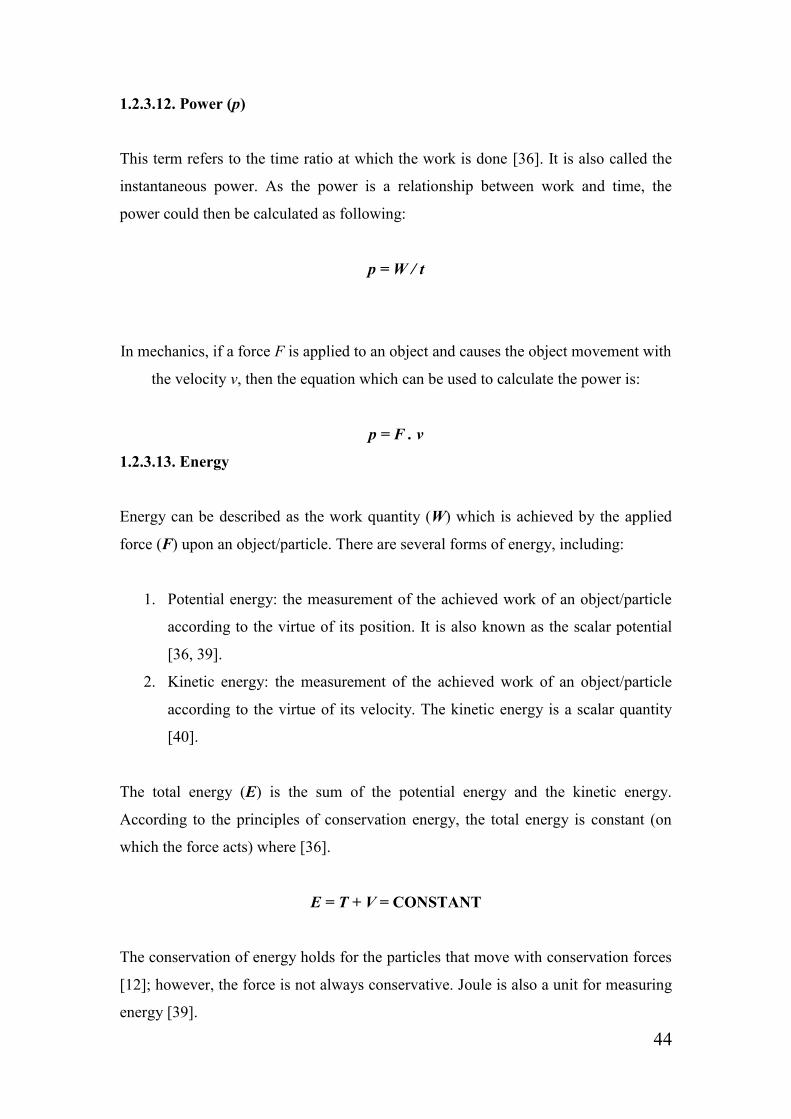
1.2.3.15. Moment
The figure below (Figure 1.10) shows the force moment F about the point x. The
moment of the force is the vector which contains the point x and the line of the action
of the force F [40]. The magnitude is |F|h, where h represent the distance between the
line of the action F and the point x. If we suggest that O is the vector xg and g is
located at any point on the line of the action F, the moment M can therefore be
obtained as M = O × F. The moment unit is m² kg s[45] ²־.
F g
h
x
Figure 1.10 Moment force calculation [45].

46
If a rigid body (disc) rotates around the axis of rotation. The liner velocity of each
particle of the body is (vi) and the distance between the rigid body particles and the
rotation axis is (ri). Therefore, vi = ri w, where the velocities and the distances of the
body particles vary from one to another, and w is the same for all of them. The kinetic
energy, such as the rigid body, will be [39]:
T = Σi ½mi vi² = ½Σi mi ri² w²
And the moment of inertia (I) will be:
I = Σ ½ mi ri²
Generally, in the case of physics, mathematical equations contain samples which refer
to one or more of the aforementioned terms. The value of each one of them is inserted
into an appropriately selected equation and results is then accordingly analysed.
In the case of dentistry, most of the experiments which are launched in the laboratory
are concerned with solid materials. Therefore, it is important to understand the
principles of solid mechanics in order to test and predict the prosthesis behaviour
during service. In order to study the principle of mechanics, different aspects, such as
forces, moments, stress and strain, will all be involved [42].
1.2.4. Mechanical testing
Mechanical testing can be defined as laboratory experiments which test material
properties and how the materials react to a specific task. The mechanical property of
the material is one of the main factors which affects the way in which materials
respond to the test. Testing the mechanical properties of the material in advance is
considered to be an important step when making sure that the produced item/device
will be appropriate for use in the service [42].
There are several types of laboratorial studies for mechanical testing. Those studies
have significantly helped to improve the material properties. Depending on the

47
purpose of fabricating the required item and by using the suitable equipment,
researchers can effectively determine the ability of the material to resist various
external forces. Therefore, it is important to understand a number of
principles/concepts relating to the field, such as:
1. Postulate of consistency [46]: despite the size or shape of the tested material,
the reaction of a known material/sample to a specific known force under the
chosen condition is expected to be similar every time.
2. Bearing capacity [42]: this is the term which refers to the ability of an object
to take the applied load before the object experiences distortion/failure occurs
in any sense. Identifying the load-bearing material is the purpose of making
the material mechanical testing.
3. Hooke’s law [42]: if a force is applied to a spring constant K and it causes a
small deformation (Figure 1.11), force F which causes a deformation (change
in the original length l) can then be calculated by using the following equation:
F = K . ∆L
L
∆L
Figure 1.11 The change in a spring original length [42].
4. Principle of uniformity [42]: this is a version of the postulate of consistency.
For simplicity, if a body has a uniformed structure and composition, the
reaction of that body to the applied load is expected to be similar in the case of
each layer. This phenomenon is known as the principle of uniformity.

48
5. Stress [42]: the acting force on an object applies to every section throughout
the object. As such, stress (σ) can be defined as the amount of force (F) that
acts per unit area (A) of the object. The stress units are N/m² or Pa, and it can
be calculated as the following:
σ = F / A
6. Strain [42]: the applied force causes changes in the object/sample length.
Therefore, strain (ε) can be defined as the change in a rigid body length per
unit original length l ۪ (the ratio of the length). Again, the strain in each unit of
the body is expected to respond similarly. It is calculated as the following:
ε = ∆L / L ۪
7. Springiness or Flexibility [42]: this is the term related to the deformation that
occurs in the material. When a force is applied to an object, the object
dimensions start to change. All materials have an elastic limit (which is the
limit between the elastic and plastic deformation) where is it able to return to
its original shape when the force is released. This concept of the material’s
physical changes is known as proportional limit (Figure 1.12). The
springiness/flexibility can be calculated by the relationship obtained between
stress and strain as:
1 / E = ε / σ
where (E) refers to the modulus of elasticity or Young’s modulus,
E = σ / ε

49
Stress
0
Strain
Figure 1.12 Relationship between stress and strain
(Proportional limit) [42].
According to these definitions, we can note that there is a direct proportional relation
between stress and strain. The strain in every unit of a chosen material increases
according to the increase of the stress. The applied force on an object causes stress to
occur throughout the object unit and accordingly increases strain, which causes object
deformation (changes in size and shape). These changes/deformations will occur only
in the cross-sectional area and along the load axis [42].
During laboratory experiment, the compressive load causes the tested sample to
experience expansion and the tensile force causes contraction. This is known as
Poisson Strain. Therefore, the Poisson ratio (v) can be calculated according to the
changes that exist in the horizontal and vertical axes of the object (Figure 1.13) as the
following [42]:
v = - εy / εx
where (εx) is the new length after the force is applied and (εy) is the new width.
Slop = Modulus of Elasticity
Elastic Range
Proportional Limit
Elastic limit

50
F F
F F
Figure 1.13 Poisson ratio [14].
In the case of ceramics and metals, the value (v) is expected to be between 0.2 and 0.4.
If v < 0.5, this then means that there will be a change in the volume of the tested
object when the force is applied. The volume strain (εv) can be identified in terms of
Poisson’s ratio and axial strain. The volume strain can be calculated from the
magnitudes of the lateral and axial strains as [42]:
εv = εx (1 - 2v)
There are several types of mechanical testing. These tests are used in order to
determine the required experimental data to be statistically analysed. The obtained
results must be summarised and compared with any available similar studies. By
using the suitable equipment, an understanding of the physical sense of
material/sample can be achieved by adopting several ways of material/strength testing,
such as [42]:
Tensile: is a uniaxial test which determines the relationship between stress
and strain. The purpose of this kind of test is to determine the maximum
required force before separation or deformation of the tested sample occurs.
The test takes place by fixing the sample to a proper testing machine (for
example: universal testing machine) from one end to a fixed part in the testing
machine, and attaching the other end of the sample to the removable part of
the machine. After this, the removable part then starts to move in the opposite
direction with a constant speed until the point when the sample breaks.

51
Compression: this type of test is carried out in order to examine the
material/sample’s resistance to the uniaxial compression load prior to the
material failing. Similarly, the compressive strength can be determined by
using the universal testing machine. Usually, the compressive strength is
grater than the tensile strength.
Shear: the shear test is mainly considered to be a uniaxial test, such as
compressive and tensile. Under the shear stress, the particles of the material
tend to slide over each other [47]. During the shear strength tests, a load is
applied at the interface of the two bonded materials until the sample ruptures.
This kind of tests is similar to the torsion test.
Flexure strength: the capacity of the material to take the maximum force
before it cracks or breaks. This test is also known as bending strength.
Impact strength: the energy required to cause a fracture in the sample during
an impact test.
Fracture toughness: for simplicity, when a specimen is subjected to an
impact force, the fracture toughness can be described as the ability of the
sample to resist the crack propagation.
Shrinkage: is the ratio of the material contraction/volume reduction [135].
Creep: this term refers to the movement or permanent deformation (plastic
deformation) of the solid material under stress [136].
Hardness: can be described as the resistance of the material to stretching.
Also, it could be identified as the measurement of the tested sample to resist
localised plastic deformation. Hardness can be measured by different ways,
such as MPa and GPa.
Fatigue: refers to the deformation that occurs to the material after being
subjected to cyclical load (stress and strain).
During practice, different types of load might be applied to an object, such as
compression, tension and shear (Figure 1.14). With this in mind, several types of
testing methods/machines are available in order to test these applied loads. All three
types of load which have been mentioned previously are presented in any test [42].

52
F F
F
F
F F
Compression Tension Shear
Figure 1.14 Type of loads [42].
In some cases, a complex load from the three kinds is applied to the same
sample/object at the same time (for example, we can find a mixture load of
compression, tension and shear in the three-point bending test) (Figure 1.15). The
three types of load can be identified in the same sample as the following classification
[42]:
Compression load: applied from the top to the middle of the tested sample
(approximately on the upper half of the beam).
Tension load: applied from the bottom to about the middle of the tested
sample (approximately on the lower half of the beam).
Shear load: applied to the whole region between the compression and tension
area.
F
F/2 F/2
Figure 1.15 Three-Point Bending Diagram [42].
Whole volume
in shear
Surface and lower
half in tension
Surface and upper
half in
compression
Line of
shear
53
1.2.5. Mechanical testing machines
There are several types of material-testing machine. Each type is used in order to
evaluate the different kinds of mechanical tests, such as impact strength, bend strength,
tear resistance, tensile force, compression force, shear force, toughness, puncture,
adhesion, peel, as will as hardness and fatigue resistance [42, 48, 49].
The corporatisation between two common testing machine used to investigate the
mechanical properties in particular materials can be achieved by using one of the
following machines:
Table 1.1 Types of mechanical testing machine [50]
Products Application Testing Mode Model
Universal
Testing
Machine
Non-metal Tension/Compression
/Flexure/Shear/Peel
CMT2000
CMT4000
CMT6000
CMT7000
CMT8000
Metals Tension/Compression
/flexure/Shear CMT5000
Hydraulic
Universal
Testing
Machine
Metals Tension/Compression
/Flexure/Shear
CHT4000
SHT4000
SHT4000W
SHT5000
SHT5000P
SHT4000G
Metals Double Axes Fatigue
Testing BIA5205
Compression
Testing Cement-brick
compression/flexure
/break CDT | CBT
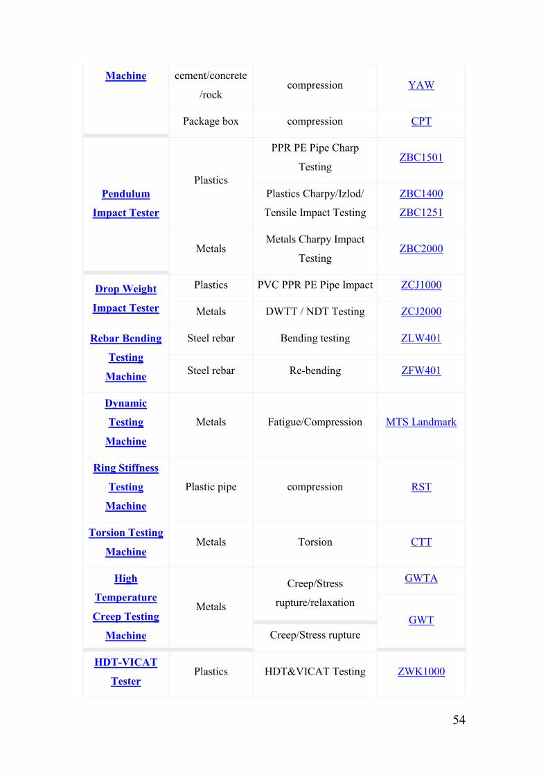
54
Machine cement/concrete
/rock compression YAW
Package box compression CPT
Pendulum
Impact Tester
Plastics
PPR PE Pipe Charp
Testing ZBC1501
Plastics Charpy/Izlod/
Tensile Impact Testing
ZBC1400
ZBC1251
Metals Metals Charpy Impact
Testing ZBC2000
Drop Weight
Impact Tester
Plastics PVC PPR PE Pipe Impact ZCJ1000
Metals DWTT / NDT Testing ZCJ2000
Rebar Bending
Testing
Machine
Steel rebar Bending testing ZLW401
Steel rebar Re-bending ZFW401
Dynamic
Testing
Machine
Metals Fatigue/Compression MTS Landmark
Ring Stiffness
Testing
Machine
Plastic pipe compression RST
Torsion Testing
Machine Metals Torsion CTT
High
Temperature
Creep Testing
Machine
Metals
Creep/Stress
rupture/relaxation
GWTA
GWT
Creep/Stress rupture
HDT-VICAT
Tester Plastics HDT&VICAT Testing ZWK1000

55
Pipe Pressure
Testing
Machine
PVC PPR PE
Pipe
Hydrostatic and burst
testing ZNY1000
Rubber pipe Hydrostatic/burst/pulse
testing ZNY2108
Steel Bottle &
Steel Pipe
Hydrostatic/burst/fatigue/
water-tightness testing ZNY3208
Plastic bottle fatigue testing ZNY4305
The machines in the schedule above should be carefully utilised (according to their
operating manual). In addition, the specimen must be properly prepared before
placing it in the testing machine. The test result will be displayed in a computer screen
which is usually attached to each one of the machines. After this, the data will be
analysed using the suitable statistical test system.

56
1.2.6. Biomechanics of teeth
Mechanics is a field of knowledge which concentrates on the action of force on the
form and motion of objects. The relationship between the oral biological system and
mechanical force can be obtained by studying the biomechanics of teeth [4, 51]. Teeth
are usually subjected to complicated dynamic loads which involve resultant forces
and moment. The movement/growth of the teeth is affected by different factors, such
as teeth loss and/or providing the patient with a dental prosthesis without re-
establishing the occlusal plane [12]. These factors can cause tooth malocclusion
which makes teeth require dental treatment to restore the tooth aesthetic and/or
function.
Mainly, teeth grow and appear in an organised row. However, when the tooth has
malposition, it can be reorganised by using either fixed or removable orthodontic
appliances. Treating the tooth orthodontically can change their position or growth by
delivering forces to the tooth, bone and/or muscles. These applied forces accordingly
create load within the periodontal ligament and alveolar bone, and subsequently cause
tooth movement [52, 53]. The teeth movement requires soft tissue between the
alveolar bone and tooth structure in order to achieve tooth movement [54]. The
following figure (figure 1.16) is showing the anatomy of the tooth structure:
Figure 1.16 Human tooth structure [6].

57
Generally, the force applied to the tooth will tend to move the tooth to a different
position in space (unit of force is grams [40]). Normally, the resistance of the free
object to any applied force is concentrated at the centre of it mass, but the centre of
resistance to movement in the tooth is located at the tooth root (halfway between the
root apex and crest of alveolar bone) [53] (Figure 1.17). The moment arm of the
applied force upon the teeth is presented perpendicularly between the tooth centre of
resistance and the point of the force application. Therefore, the teeth will tend to
rotate around the centre of resistance (Figure 1.17) [53].
Figure 1.17 The centre of resistance to movement in the tooth [53].
Generally, there are some factors which are known to affect the teeth biomechanics.
In 1979, a study was conducted with the aim of studying a number of aspects,
including the biomechanics of the natural teeth. The author has calculated the stresses
(by using a computer program) which are associated with a given applied force on the
teeth. A model of a normal tooth has been created, and a load was subsequently
applied to the centre of the crown. The model of the natural tooth was created twice
(both with and without the periodontal ligament). The models were created in order to
identify the role of the presence of the periodontal ligament. Following, the reaction
of the tooth in response to the applied force was studied in each case. The results
show that the periodontal ligament controls the biomechanics of the natural teeth as it
reduces the stress concentration at the socket wall and works as a good shear translate
layer [55].
Centre of
resistance/rotation
Root apex
Moment arm
Applied
force
Alveolar
bone

58
Brunski J.B. and Hipp J.A. carried out an in vivo study in 1984 with the aim of
measuring the applied forces on endosteal dental implants. During the study, the
researchers exposed the factors for consideration when applied forces are measured.
The authors designed a recording system and transducer to measure the force
components along the occlusalapical axis on dental implants in a number of dogs.
Titanium implants were made and provided with a hole in the neck portion, thereby
allowing the transducer to be inserted. After this, three unit prostheses were fabricated
and casted using cobalt-chrome alloy. Moreover, six implants were placed in the
premolar surgically and allowed to heal. Following, the fabricated fixed prostheses
were cemented on the prepared abutments using glass-ionomer cement; the results
were subsequently recorded. The study reports that there was a satisfactory in vivo
measurement of the forces, and that no failure occurs because of the corrosion or
moisture at the intraoral environment. Moreover, it has been found that, the location
of the implants in the mouth can affect the results as the applied loads vary form one
place to another within the mouth/teeth. Furthermore, the obtained results can be
affected by the material properties of the abutments teeth and the tissue between the
teeth and the implants [56].
We can conclude that the condition of the oral soft tissue influence the biomechanics
of teeth. These soft tissues are considered to be an important element when reducing
the stress of the applied loads on teeth/prosthesis. The place of the applied force
varies from one location to another along the tooth’s surface/location (anterior or
posterior) [57-59]. Moreover, the condition of the abutment teeth/tooth has an
influence on the denture stability [1]. The used materials on the dental prosthesis have
an affect on the denture resistant to any external force. However, the in vitro studies
can simulate the oral environment and provide acceptable results and anticipation to
the oral environment, whereas an in vivo study of the exact applied forces on a fixed
denture (placed at the patient mouth) can be achieved by using a suitable equipment;
for example, the transducers and the recording system.

59
1.2.7. Methods of measuring bonding and attachments in dentistry
Because the field of dentistry has various branches, each kind of dental prostheses is
retained in different way. These dental appliances are subjected a variety of applied
forces on different areas along the dental restoration. Accordingly, it would be useful
to point out that, dentists are classified according to their speciality. Each type of
these specialities is concerned with a particular type of dental restoration, for example:
1. Prosthodontic: is concerned with dental prosthesis. This is the treatment
achieved by replacing the missing natural teeth/tooth with artificial
teeth/tooth, such as by utilising a fixed or removable partial denture.
2. Endodontic or (inside the tooth): this branch is concerned with treating
anything which occurs in the tooth itself, such as caries, cracks, and root
canal infection.
3. Orthodontic: concerned with treating the tooth malocclusion (when the teeth
are not in their normal position).
4. Maxillofacial: this branch is concerned with restoring the oral soft tissue with
artificial parts, such as replacing part of the jaw (with artificial teeth and/or
jaw). Moreover, this field includes restoring some other facial parts, for
example eyes, ears and nose.
Dental prostheses include single crowns and fixed bridges experience many loads
applied in different directions and locations. Mainly, these loads could be tensile,
compressive or shear [42]. During mastication, one or more of these loads will apply
to the restoration. As a result, the artificial restoration might bend or break. However,
the oral prostheses are not affected by the mastication forces only, although they
might be subjected to other forces occurring from bad habits or sociological problems,
such as biting tough objects and sleep bruxism [60].
The artificial crown/bridge particles slide over each other under the shear stress [47].
In order to obtain the shear bond strength, two materials are bonded with each other
by using a appropriate adhesive material. After this, the load is applied at the junction

60
between the two materials until they separate from each other [61]. Although the
bond strength might vary from one place to another along the tested sample, a lot of
studies consider this way of testing the bone strength as an ideal way of testing the
shear bone strength. There are different ways to test the material behaviour in such a
situation; for example, flexural and tensile test. However, the shear bond strength test
is the most popular test [62].
The best selected bonding test which could be used in order to test the material
behaviour in service can be obtained by using a model simulated by using FEA. This
model is able to analyse the stress distribution in any suggested clinical case.
Therefore, it gives researchers the opportunity to make the best choice between tensile
and shear bonding test [63].
There are a number of environmental differences between in vitro test and in vivo
circumstances, such as temperature and saliva [64]. Furthermore, the presence of the
tensile stress on the dental prostheses usually causes separation between the porcelain
and metal [65]. So that, failure could be a result of the abnormal stress distribution
within the tested sample [66].
In 1997, a study was undertaken with the intention of investigating the cohesive
failure in the shear tests. The study did not concentrate on increasing or reducing the
adhesive agent properties because it suggests that the reason of the cohesive failure of
the shear test is related to the mechanics of this type of tests. Therefore, the specimens
were prepared by making two-dimensional finite element models for
dentine/composite. Following, a series of loads were applied at the junction between
dentin and composite. The experiment shows that the fracture occurred in the
composite surface (beside the loading point) and continued along the junction. After
this, the fracture extended in the dentine. The dentine fraction was about 40 to 50% of
the fractures. The outcome of the study identified that, by increasing the bond strength
the cohesive failure will increase. The conclusion is that, regardless of the adhesive
material properties, the cohesive failure in dentine will occur because of the brittle
nature of the used materials and the test mechanics [67].

61
Another study was conducted in 1980 in order to estimate the stress distribution
within a number of porcelain fused to metal samples. Each sample was tested using a
different type of bonding test: three-point flexure test, four-point flexure test, semi-
circular arch flexure test, tension/shear test, pull shear test, push shear test conical
interface shear test, and parallel shear test. It was obvious in all types of test that the
stress was abnormally distributed and not concentrated at a single point. However, the
study reports that the lowest opportunity of having a tensile stress concentration and
normal stress distribution can be achieved by using the rectangular parallel shear test
with rectangular-shaped bonded surface, where the force is applied to the junction of
the tested sample [66].
In 2003, another author used a microscope to examine the samples on a study of
micro-tensile bond strength of resin-composite to ceramics. During the experiments,
he noticed that the fracture between the two materials always started adhesively. In
addition, no bulk fracture has been identified in the composite or ceramic. The
observation in this study shows that when comparing to the conventional tensile and
shear tests, the stress was normally distributed in the micro-tensile test [68].
However, this type of test cannot be carried out easily because the specimens need to
be fixed (using cyanoacrylate resin) to stainless steel grips which are presented in the
micro-tensile machine. Furthermore, the samples take a lot of time in order to be
prepared. Moreover, sometimes, the samples might be separated from grips when the
force is applied (if they are not properly fixed to a machine) and the results obtained
might not by accurate. In conclusion, it is simpler and easier to use the micro-shear
test rather than this type of tests [69, 70].
In 2006 and 2005, two studies were conducted in order to investigate the bond
strength of zirconia-based ceramic crowns by using different types of cement. A
number of natural extracted teeth were prepared, and the crowns were cemented to the
extracted teeth. The authors used a pull-off test to examine the bond strength of the
cemented crowns. The crowns were fabricated with retentive bars in order to be
attached to the universal testing machine, which pull the crowns off and measures the
force to failure in each group. The results show that there is no significant different in

62
the retention between these types of cement. The methodologies which were used in
both studies were considered similar to the situation in patient mouth [71, 72].
Many studies suggest using a tensile load to measure attachment strength. In 1995, a
study was undertaken to investigate the amount of force required to dislodge two
types of dental clasp. The author tested the retention of these clasps in three different
situations, and tooth preparations were made on the upper right first premolar and
second molar. After this, three casts were poured (two prepared teeth were presented
on each cast) and six full crowns were casted using cobaltchromium alloy. The
crowns were cemented to the casts and the clasps were attached to each crown. The
experiment took place using universal testing instruments. For each cast, the tensile
load was applied until the clasps completely dislodged from the crowns and the
maximum force was recorded. The results show that there is no significant difference
between the mentioned groups. However, the study indicates that retention can be
increased by increasing the clasp length [73].
In an attempt to compare the retention between C clasps and I bar with hidden clasps.
a study was launched in 1996. Two extracted natural teeth (first premolar and second
molar) were fixed into an acrylic resin model. After this, the framework, including the
required clasps and a bar, was fabricated without the guiding planes. Form each
design, nine frameworks were tested using a tensile test machine. Artificial saliva was
lubricated over the natural teeth. The frameworks were then placed into the empty
space between the two teeth and pulled ten times; the retention force was recorded.
The study shows that the retention of the frameworks which carry the hidden clasp
vary when compared with the other formworks. Furthermore, the absence of the guide
plane caused the removable denture withdrawal [74].
In conclusion, many aspects should be taken into consideration during testing the
bond strength, such as the test mechanics, materials involved, place of the load, type
of the adhesive material. These components can make the bond strength results vary
from one experiment to another even the shape and the bonded surface area of the
sample might have an effect the bonding strength [75]. The shear testing considered
as easy, fast simple, ideal, and the most popular test. Also, it is more accurate the
comparing to some other types of bonding strength test. The shear bond strength

63
results are influenced by the cross-head speed; the suggested head speeds are 0.5 and
0.75 [64]. However, by using FEA, a model can be simulated to analyse the stress
distribution and to accordingly give the researchers the best choice between tensile
and shear bonding tests. On the other hand, it would be more appropriate to use the
tensile test to identify the retention strength of the attachments which are retained
mechanically. If clasps are used to in order to fix dental attachments, the longer the
clasp used, the better retention will be obtained. Generally, the obtained results
regarding the bond/retention strength should be taken with caution in order to obtain
the correlation between in vitro and in vivo situations [64].
1.2.8. Denture life span and the factors which affect longevity of the
dental prostheses
Dentures do not last indefinitely. Over time, they will need to be adjusted, rebased or
remade periodically. The time taken before the need to replace the denture varies
depending on many factors. An additional consideration is that the tissue of the mouth
and gum can change in shape as long as the patient is getting older [76]. The material
which is used in the removable denture must be wet at all times and, because of this
reason, should be placed in quite hot water when it is removed out of the patient’s
mouth [77]. If the denture becomes dry, it might change in dimensions; such changes
cause the denture to loosen, thereby causing it not to fit properly. In addition, the
removable partial dentures have sensitive parts which could potentially bend or easily
break; therefore, required conscientious care when removing from the mouth is
required. Moreover, a patient may have caries or teeth dislodgment, which also affects
the denture’s stability; as such, it is wise to visit the dentist every six months for a
check-up [12].
In 1993, a study was conducted in order to evaluate the clinical variables affecting the
adhesion of fixed prostheses. A total of 141 fixed partial dentures were subjected to
controlled circumstances from 1985-1992 (six years). Many aspects of the tested
samples have been recorded, such as measuring the sample’s mobility, level of
attachment, and the pocket depth. After this, dental preparations were made by

64
different dentists, and dental impressions were taken and sent to the dental laboratory.
The required fixed prostheses were fabricated and cast with chromo-cobalt alloy.
During this study, three factors were estimated: prosthesis location (mandible/maxilla,
anterior/posterior), metal condition (pyrolytic/tribochemical silane coating and/or
sandblasting/electrolytic etching) and tooth preparation (less invasive/retentive). Only
24 failures of the examined fixed partial dentures were recorded. Most of the observed
failures occurred due to adhesion dislodgment between the metal and cement. Despite
the location of the dental restoration (mandible/maxilla, anterior/posterior), the result
shows that the preparation technique increases the possibility of the prosthesis’s
survival. Furthermore, the metal conditioning (sandblasting/electrolytic etching) has
no influence in increasing the survival rate of the FPDs [78].
In 1984, a study was established by Sigvard Palmqvist and Bjorn Soderfeldt with the
objective of determining the factors which affect the FPDs, retainer, and abutments
longevity. The study finds that the most important reason associated with the
longevity of prostheses is the materials which are used for the denture fabrication,
such as gold and cobalt-chromium alloys. In addition, the findings also suggest that
the gender (male/female) and the age of the patient have critical influence on the
denture’s overall lifespan. The study also reports that the risk of losing the FPDs
increases when the abutment tooth is endodontitally treated. The researchers further
state in their study that having a combination of the previously mentioned factors
decreases the length of required denture service [79].
On the other hand, many studies suggest that the increase of the patient’s age has no
influence on the denture’s longevity. In 2009, a study was carried out in order to
investigate the relationship between the increase of patient age and the fixed
prostheses’ survival. The study includes medical databases between 1980 and 2008
for studies on humans, reporting on the influence of age on the longevity of fixed
dentures. The database also includes a hand search to a number of journals and any
available relevant articles and databases; however, the chosen studies were published
between 1985 and 2007, for a total of 2,811 patients aged between 17 and 94 years
old. However, although the study reports that there are some evidences of higher
failure rates in the case of middle-aged patients, the study nevertheless concludes that

65
there age increase is not considered to have an impact on the survival of the fixed
prostheses [80].
Another study was undertaken in 1997 with the aim of evaluating the longevity of
fixed partial dentures and the reasons behind the failure of fixed partial dentures. Fifty
patients were included in the study with a total of eighty-nine FPDs (384 units). A
clinical and retrospective chart was designed for those patients during a six-month
period. More than fifteen percent (53 unites) of the fixed partial dentures failed: the
prostheses failures were due to caries, porcelain failure, defective margins, fracture on
the tooth structure, fractured post and core, periapical involvement and perforated
occlusal surfaces. In this study, the majority of FPD failures were due to the presence
of dental caries. The study states that the rate of the fixed partial dentures’ longevity
ranges from 4.1 to 16 years. However, another study suggests that the FPDs length of
service is 11 years, and that all restoration lengths of service are about 8.3 years [81-
83]. Many studies suggest that the failure of FPDs occurs due to the same previous
reasons [84, 85].
In conclusion, there is no risk of denture loss according to age increase, especially if
the patient has a good tooth and generally good health. The accurate tooth preparation
increases the denture stability/retention, as well as the denture’s overall length of
service. The metal conditioning such as sandblasting/electrolytic etching and the
location of the denture such as anterior/posterior, tooth/teeth all have no influence in
the denture’s longevity. The most important elements which affect the denture’s
overall lifespan are the teeth preparation, the condition of the abutments and de-
bonding of the cement, as well as the material used for the fabrication of the
prostheses.
There is no agreement surrounding how long dentures can actually survive. After a
period of time often several years they will undoubtedly experience problems during
chewing and a loss of appearance (natural appearance) [76]; even with the right set of
circumstances, the denture could still be broken or not fit perfectly. However,
removable of the partial/complete denture often lasts for four to seven years, whilst
fixed partial dentures or ‘crown and bridge’ may last for more than that. Implants, on
the other hand, could last forever [12].
66
Chapter 2
Aims and Objectives of the
Study

67
2. Study Aim and Objectives
2.1. Problem statement
Owing to the implications occurring from losing one or more natural teeth, new types
of extracoronal or intracoronal dental prostheses have been developed in order to
provide patients and practitioners with better alternatives to dental treatment options.
Notably, restoring the missing teeth along with the conservation of the tooth’s
structure has been one of the most important goals of any related dental treatment [86].
Fixed dentures are one of the most popular dental treatment solutions as they are
considered to have a reasonable price and provide good function. Conventional fixed
bridges, cantilever bridges and Maryland bridges are examples of such fixed
restorations.
Although a great deal of years have passed since various fixed bridge designs have
been used, there are nevertheless some major problems associated with these,
including destroying neighbouring tooth anatomy owing to massive preparation, de-
bonding (adhesive failure), and recurrent caries in the abutment prepared tooth [1, 4,
14, 82]. Furthermore, once the denture is cemented, it is most likely that the prosthesis
would need to be remade if the abutment root canal needed to be treated or dental
caries were presented [14].
In this study, a number of new fixed partial denture models have been suggested in an
attempt to determine the possibility of producing them at the dental laboratory. The
selected bridge designs will be studied individually. Subsequently, it will be
fabricated by using a suitable biocompatible dental material. The usefulness of the
new design will be examined by testing the level of stability and the ability to resist
the oral force, such as the mastication force, in order to assess the new design’s
overall effectiveness.
68
2.2. Study aim
The aim of the current study is to produce a new fixed partial denture design with
minimum abutment teeth reduction.
2.3. Study objectives
1. To obtain a new type of bridge which is able to be fixed using mechanical
force rather than chemical force (i.e. cement).
2. To evaluate the dislodgment resistance of the new design by comparing it with
the conventional three unit fixed bridge.
2.4. Hypotheses
1. Null hypothesis: There is no significant difference between the
dislodgment resistance of the new bridge design and the conventional
three-unit fixed bridge design.
2. Alternative hypothesis: There is a significant difference between the
dislodgment resistance of the new bridge design and the conventional
three-unit fixed bridge design.
69
Chapter 3
The New FPD Design
Development
70
3. The New Design Development
3.1. Introduction
Many studies have suggested different denture designs in order to examine the
opportunity of obtaining varying dental appliances and treatment options. Those
attempts have concentrated on establishing a new way of fabricating a new type of
dentures that are possible to be made, retained acceptably and minimise the negative
consequences of selecting a particular dental treatment.
Some of the studies have suggested designs, which have succeeded sufficiently whilst
others have failed. The success of the new designs has significantly helped to improve
the appearance and overall function of dental prostheses. Nevertheless, the failure of
any tested design is considered to be important and is highly respected, owing to the
fact that it confirms the failure of the tested model and accordingly explains the
reason why it is not possible to use that design for a particular service. The obtained
results from the failed attempts and subsequent studies can be used in the future to
save the researcher’s time by avoiding the repetition of any similar models. Moreover,
it can also be used in order to determine a way of solving the problems associated
with the failed design.
One of the main aims of this study is to produce a new fixed bridge design which
provides retention by only macro-mechanical means (clasps) in order to fix the bridge
in the patient mouth and to thereby restore the missing tooth/teeth. The idea of the
new bridge is focused on fabricating an artificial tooth with two clasps. These are
embedded into each abutment tooth from the buccal and lingual sides (four clasps in
total). The clasps should be fixed to the abutments with out any cement and the
bridge is then will have the ability to be removed at any time. Fixing the denture
without using any cement would be helpful to avoid numerous disadvantages
associated with cemented fixed prostheses. Disadvantages such as: difficulties of
cleaning the covered abutments, failures due to the de-bonding of the cement and
difficulties of treating abutments teeth after cementation [87].
The new FPD design should be able to achieve the following goals:
Be permanent, but can be removed occasionally for cleaning.

71
Decreases neighbour teeth preparation (natural teeth).
Offers a lower cost than dental implants.
In this study, a number of new fixed partial denture designs will be suggested and
investigated in an attempt to improve the negative aspects of the fixed partial dentures
[87], which have been used recently. Subsequently, the mechanical properties of the
recommended design will be tested in order to determine the possibility of
considering this bridge design as an alternative treatment option.
According to the problems associated with the utilisation of the cement to retain fixed
prostheses, and also owing to the massive natural abutment teeth preparation, an idea
emerges in an attempt to retain a fixed prosthesis with the use of four clasps to be
embedded into the abutment teeth. When the shape of the new design (original design)
is considered and the fabrication procedure has been initiated, the design has
highlighted various technical difficulties in terms of its fabrication. Accordingly, a
number of modifications were made to the original design prior to the final shape of
the design being considered.
3.2. The original design (first model)
The first model comprises five components: one major component and four minor
components. The first component is the major part of the model, which functions as a
pontic. This part has two clasps, which are a feature of the major component (Figure
3.1) These clasps are designed to fit into the grooves, which are prepared in advance
on the buccal side of the abutment teeth.
Figure 3.1 The original design pontic.
Two buccal
clasps

72
Once the pontic is constructed, four minor parts will be designed. The four minor
parts include two individual clasps and two bolts (Figure 3.2). The two bolts are
rectangular-prism shaped. The clasps at the location of attachment to the pontic
feature a hollow rectangular column. The pontic features two hollow cube-shaped
projections at the upper and lower parts of the lingual side of the pontic. These
projections overlap the upper and lower parts of the rectangular column of the clasps;
this is where the clasp will be bolted in place vertically; thus, fixing the clasp in place
to the pontic (Figure 3.3).
Figure 3.2 The Original design components.
Figure 3.3 Five components of the original design fixed together.
3.2.1. Problems with the original design
Upon fabricating the first suggested model and carrying out further reading, it became
apparent that the model required modification in order to solve two main issues:
Two bolts
Two
individual
clasps with
hollow
rectangular
columns
The pontic
with two
hollow
cube-shaped
projections
Two bolts
inserted
into the
clasps
vertically The two
individual
clasps fixed
in place

73
1. Casting difficulties of the invested wax pattern; and
2. Fabricating difficulties and time-consuming in-laboratory activities.
It became clear that this design cannot be cast into a metal framework owing to the
small parts of the design; more specifically, the hollow-cube projections from the
pontic, as well as the rectangular prism of the clasps. The remaining mould from the
wax-burnout procedure was not able to resist the speed at which the metal entered the
mould. Importantly, during the flow of the metal within the mould, the thin layers
were found to break easily.
The wax fabrication of this model, although possible, was found to be very difficult to
execute precisely owing to the small parts contained within the design. It may be
possible to construct this model in a factory due to the standard of precision available
in modern technology; however, considering the practicalities of constructing this
model, the two main issues concerning the wax fabrication and the casting procedure
justify further modification in order to enhance the suggested design.
3.2.2. Modifications to the original design
In light of the problems established with the first model, a series of adjustments were
made in order to overcome the previous design issues, which will form an enhanced
second model. The problems which occurred owing to the casting and fabrication
difficulties were minimised during the design of the second suggested model.
Generally, the second design will consist of more than one part joined together, and
will act as one unit. The first part (major part) will work as a pontic. It will include
two clasps extended only from the buccal side to each abutment tooth (Figure 3.4).
The clasps will be inserted into a groove shape, which will be prepared, in advance,
on each abutment tooth. At the distal-occlusal and mesial-occlusal surface of the
major part, there will be two rest seats to increase the denture stability against the
compressive force. Furthermore, the major part will include an appropriate space in
order to adapt the second part and to thereby fix them together with the use of a
suitable denture locker.

74
Figure 3.4 Occlusal View of the Major Part.
The second part of the bridge can be referred to as the minor part. This part also has
two clasps which are extended from the artificial unit toward the lingual side of the
abutments (Figure 3.5). When the major and the minor parts are joined together, each
clasp from each part will be adapted into the prepared abutment teeth groove in order
to surround the neighbour teeth buccally and lingually, and to thereby hold the
denture in place so as to provide retention. In addition, the minor part will include
small vertical opening in which the connecting device will be inserted.
Figure 3.5 Occlusal View of the Minor Part.
Major part
(Pontic)
Occlusal
Rest Seats Natural teeth
(abutments)
Buccal
Clasps
Lingual
Clasps
Minor part
(Pontic) Natural teeth
Vertical
opening

75
The third part, the bridge locker, works as an attachment between the two other parts,
and prevents bridge movement. By using suitable instrument (e.g. screwdriver), the
locker will be fixed in place and the bridge will remain stable. If an instrument can be
made for this purpose, the patient will be able open and close the locker for cleaning.
In conclusion, the idea of the second design will be focused on fabricating an artificial
tooth, which consists of three parts. The two main parts will have two clasps/each,
which will be extended from each part towards the neighbour teeth (buccally and
lingually). Firstly, the major part will be placed into the gab of the missing tooth and
the clasps will be inserted into the buccal grooves of the prepared teeth. Secondly, the
minor part will be attached to the major part and the clasps will be inserted into the
lingual grooves of the prepared abutments. Subsequently, the two parts (major and
minor part) will be fixed together using a suitable bridge locker.
3.3. The modified original design (second model)
This second model has only three parts rather than five; this was decided in an attempt
to facilitate the fabrication procedure, thus minimising the complications associated
with the fabrication. Furthermore, the design of Model 2 does not feature the multiple
small parts which were recognised as causing difficulties in casting Model 1.
The first part of the second model is referred to as the major part. The major part is a
single entity comprising two clasps extending from the pontic to the neighbouring
teeth on the buccal side (Figure 3.6). On the occlusal surface of the pontic, there is a
box-shaped indent, at the bottom of which there is a hole into which the screw is
placed in order to fix the first (major) part to the second (minor) part (Figure 3.7)
The minor part also has two clasps extending from the pontic but from the lingual side,
similar in design to the major part. An exception in the design is a box-shaped
projection rather than an indent (Figure 3.8). This projection will fit into the major
part’s indent, which will enable the screw fix to be put into place vertically, thus
bringing the two parts together whilst the clasps surround the neighbouring teeth on
the buccal and lingual sides (Figure 3.9). As the projection is located at the centre of
the occlusal surface of the pontic, it will be possible to make it as thick as possible in
order to be casted without experiencing those difficulties associated with Model 1.

76
The third part the bridge locker worked as an attachment between the two other parts,
and notably prevents bridge movement (Figure 3.10). Through the use of a
appropriate instrument (e.g. screwdriver), the locker/screw is fixed into place, thus
enabling the bridge to remain stable. With the same instrument, it will be possible to
remove the locker for cleaning purposes.
Buccal clasps
Small
hole
Box-shaped
indent
Figure 3.7
Side view of
second model
major part
.
Side view of
second model
major part
Lingual clasps
Small
opening
Box-shaped
projection Figure 3.8
Occlusal and
side view of
second model
minor part
Rest
seats
Figure 3.6
Occlusal view
of second model
major part

77
Figure 3.10
Side view of
the second
model
Figure 3.9
Occlusal
view of the
second
model

78
3.3.1 The second model fabrication
The fabrication procedure of this design involved fabricating the major part first and
the minor part second. It is recommended to fabricate the major part first because it is
practical to use the indent to shape the projection rather than the other way around. It
is noted that this will be helpful in shaping the projection of the minor part more
precisely, thus maximising the precision of the fit when the parts are brought together.
Although this practical step was taken towards an acceptable standard of precision,
soft wax was used to ensure the maximum fit when forming the projection of the
minor part inside the indent of the major part. In order to achieve this, the major part
is fabricated completely (Figure 3.11); the minor part is then fabricated out of wax but
without the projection.
Figure 3.11 The second model major part.
In order to fabricate the projection of the minor part, a procedure is carried out
whereby the two parts are placed together, with the wax melting on the underside of
the pontic at the point at which where the two parts meet, temporarily bonding the
major and minor parts. The screw is then partially fixed in place inside the major part
and the die lubricant applied to the inner walls of the indent and the screw so as to
prevent the wax from sticking to the inner walls of the major part. The soft wax (soft
tooth carding wax 500g, kemdent, Purton, UK) was then adapted into the presented
gap using the fingertips. Once the wax has been precisely adapted to the presented
gap, the wax then needs to be melted in order to securely join the formed projection to
Box-shaped
indent
Two rest
seats

79
the minor part (Figure 3.12). The screw is then removed, leaving a hollow space in the
projection, and the two parts are then separated from each other to be cast (Figure
3.13)
Figure 3.12 The second model (Major and minor part).
Figure 3.13 The second model wax patter.
3.3.2. Problems with the modified original design (second model)
There are two main problems with this design which will jeopardise the functionality
of this bridge design:
1. The precision of the fit between the indent of the major part and the projection of
the minor due to the limited working area; and
Soft wax
adapted
into the
indent
Buccal and
lingual clasps
Box-shaped
indent
Minor part
Minor part
Minor part

80
2. The horizontal groove on the occlusal surface of the pontic.
Although a micro-millimetre gap will occur between the indent and the projection of
the two parts, when the bridge is fabricated, this first problem is of particular concern
as it will be liable to structural instabilities. Furthermore, it may allow particles of
food to enter, thus meaning the design will be unlikely to be sufficient for patient use.
Furthermore, there is a second problem concerning the groove that appears on the
occlusal surface of the pontic, which extends from the distal side of the pre-molar
through to the mesial side of the molar. This is owing to the junction between the two
individual parts, i.e. the major and minor parts. The main problem is that food
particles may enter this groove. As the groove is on the occlusal surface, this problem
is compounded by the mastication force pressing the food into the groove, which will
cause difficulties in cleaning, therefore causing bad odour.
In light of these two problems, further modification is required to overcome these
issues in this second suggested design; therefore, a third suggested model will be
represented below.
Due to the problems associated with each design (first model and second model) we
have suggested that the hollow parts of both models to be closed and fixed to the
major part by using suitable dental cement. In this case, although those
designs/models did not achieve the aim of being removable, they will be considered
as conservative restorations and may show an acceptable resistance against the
mastication force if they have been cemented. Both designs will require further
investigations.
3.3.3. Modifications to the second model
In light of the problems established with the second model design, a series of
adjustments were considered in an attempt to overcome the previous models’ design
issues, which will therefore form a third and final model. The two problems occurred
owing to the unsatisfactory fit between the indent and the projection, as well as the
groove that was present on the occlusal surface of the pontic, both of which are
rectified in this final design.

81
3.4. The final design of the new suggested FPD
This model comprises three parts. The first part referred to as the major part works as
main part of the pontic. It has two clasps, both of which are adapted into the buccal
side of the prepared abutment teeth. The major part has a thin projection extended
from the lingual side in order to form a full occlusal surface as one unit (Figure 3.14).
On the mesial-occlusal and distal-occlusal surface of the pontic, two rest seats are
fabricated (adjacent to the pontic) (Figure 3.15).
Figure 3.14 Distal view of the final design (new FPD design).
Figure 3.15 The new FPD design attached to abutment teeth.
Major part
Thin
projection
Minor part
Buccal
clasps
Acrylic
resin block
Two
occlusal
rest seats
Lingual
clasps

82
The second part referred to as the minor part also has two clasps, both of which are to
be adapted into the prepared abutment teeth on the lingual side. The minor part is
designed so to allow the major part’s projection to form the occlusal surface. Notably,
both the major and minor parts are fabricated with a hole located lingually at the
centre of each wall of the two parts (Figure 3.16). Furthermore, when the two parts
are brought together, the pontic is formed (Figure 3.17). The two holes then allow a
screw to be fixed horizontally in place in order to fix the two parts together.
Figure 3.16 Horizontal view of the major (up) and minor (down) parts.
Figure 3.17 Buccal (Horizontal) view of the New FPD design.
Horizontal
Holes
Major part
Major part

83
3.4.1. Advantages of the final design
The final model was designed with the aim of removing the junction on the occlusal
surface of the pontic to the lingual side. The final design now features an occlusal
surface which is fabricated as a single entity; this will drastically minimise the
possibility of food particles being pressed into the junction between the two parts
during mastication, whereas this was a certainty with the second model.
The final model was also designed with the aim of rectifying the problem of poor fit
between the indent and projection in Model 2. In order to achieve this, the projection
and the indent aspect of the design were removed completely; thus, the final model no
longer relies on a screw being fixed at this point where structural instability is a risk.
As stated, the final model retains structural stability by a horizontal screw attaching
the two parts together at the bulkiest possible area.
The third model, Model 3, has ensured that the previous design flaws in the first and
second designs are not repeated. The final model does not include very small parts
which are difficult to be fabricated or which are otherwise impossible to cast, as was
experienced previously.
3.5. Advantages of this type of bridge (why it is better?)
When comparing the conventional and cantilever-fixed bridge, the new bridge will be
able to save most of the remaining teeth (abutments) structure. It is clinically quicker
than all types of FPD prostheses, less expensive to implement than the implants and
does not require any surgery. Although the Maryland Bridges save most of the tooth
structure, it is usually placed over the anterior teeth. The new FPD design has the
advantage of being more capable of resisting the chewing force, and can be applied in
the posterior area. Unlike with the Maryland Bridges, this new bridge should not be
affected by teeth dislodgment [1] as the bridge is tightly fixed to the abutment teeth.
Another advantage could be by carrying out the experiment of fixing the bridge
without any cement, and whether the outcome is successful; in this case, the denture is
going to be fixed when it is placed into the patient mouth and the locker is closed,
which is then removable upon opening the locker. Unlike the other types of fixed
84
partial denture designs, the success of this experiment will give the patient the chance
to remove the denture from his/her mouth. This will then increase the advantages of
that bridge, owing to the fact that the patient will be able to take it out to clean his/her
teeth and the denture frequently. The decay which occurs under the fixed denture is
considered to be one of the main factors affecting fixed partial dentures lifespan [4],
and so this experiment could help to overcome this issue.
One of the fixed dentures disadvantages is that it is not adjustable; when the denture
experiences any problems or issues and needs to be replaced, it will then be very
expensive for the patient. Because the new bridge consists of two parts, this means
that the denture is more likely to be replaced in one part only when the decay appears
on one side of the abutment tooth; therefore, the prosthesis will be replaced partially,
accordingly saving materials. Subsequently, the denture might then be able to live
indefinitely. Also, it might be possible to treat the root canal of the abutment teeth
without removing the bridge, owing to the occlusal surfaces of the abutment teeth
being clear.
3.6. Evaluation of enamel thickness
3.6.1. Introduction
Enamel is the external layer of the tooth and the toughest mineralised tissue of the
human body. It consists of nanorod-like hydroxyapatite crystals, which are organised
into a micro-architectural unit [88]. Many studies have conducted to measure the
enamel thickness and subsequently determine that an individuals’ dental enamel
varies in thickness depending on many factors including species, sex and type of the
examined tooth [89-96]. However, if the two teeth from the same type was examined
a slight deference might be found.
Generally, the upper part of the tooth enamel is the thickest part especially in the
cusps which gets thinner towards the gingival area [96]. According to many studies
which have been conducted to measure the enamel thickness, they have subsequently
determined that the maximum thickness of human enamel (upper third molar) are
located in the range of up to more than ~2.25 mm at the cusps area [90, 97, 98].

85
The second layer of the tooth structure is known as the Dentin; it is covered and
protected by the enamel. Dentin mainly consists of minerals [99], and has small
channels which extend from the inner tooth pulp to the enamel border [100]. When
the tooth has a crack or caries, the Dentin is exposed and patients can then feel
sensation or pain through those channels [100]. Therefore, it is highly recommended
that tooth reduction be kept to a minimal and within the enamel area [101].
3.6.2. In vitro study to evaluate enamel thickness
In the current study, an in vitro study has been launched with the objective to measure
the enamel thickness of a number of adults’ permanent second premolars and second
molars. This study has focused on measuring the enamel thickness both buccally and
lingually in order to determine the accurate location and exact depth of the tooth
preparation so as to obtain suitable space to set the clasps of the new suggested
design. The enamel thickness has been measured approximately half way between the
tooth cusp tip and the enamel-dentin junction (the bulkiest enamel area) (Figure 3.18).
Figure 3.18 The location of the measured area of the sectioned teeth [6].
In order to evaluate the enamel thickness, a number of second premolar and second
molar (n=10) have been sectioned from the middle of the tooth (cut into two halves)
The measured area
(Bulkiest area)

86
and the enamel has been measured. The measurements were carried out by using
electronic caliper (SPS electronic caliper, 432-025, Mitutoyo) (Figure 3.19).
Figure 3.19 Electronic caliper (SPS, 432-025, Mitutoyo).
Table 3.1 Illustrates the enamel thickness of the second molar in mm:
The Depth is the distance between the dentin and the external surface of the second
molar at the bulkiest enamel area (horizontally).
Tooth Buccal Depth Lingual Depth
Second
Molar
1.29
1.19
1.47
1.57
1.62
1.64
1.59
1.77
1.56
1.38
1.44
1.12
1.23
1.37
1.35
1.55
1.35
1.49
1.26
1.21
Mean 1.51 1.34

87
Table 3.2 Shows the second premolar enamel thickness in millimetres:
The Depth is the distance between the dentin and the external surface of the second
premolar at the bulkiest enamel area (horizontally).
3.7. The dimensions and location of the new bridge
According to the previous study, we can conclude that the suggested design clasps can
get into the abutments tooth (enamel) with a maximum depth of ~1.5mm in the buccal
side and ~1.3mm from the lingual side of the second molar, to be within the enamel
level. The preparation depth on the second premolar can be made up ~1.4mm on the
buccal side and ~1.2 from the lingual side. These findings coincide to a large extent
with the previous study of Anthony et al. [102]. Moreover, by looking at a number of
previous studies it might be possible to conclude that the enamel thickness of the
second molar (lingually and buccally) may be approximately in that range [98, 102-
104].
The tensile strength of the new bridge might be improved by making sharp angels in
the inner surface of the tooth preparation, where denture toughness can be increased
by making the clasps thicker during fabricating the bridge in the dental lab. However,
in this stage the preparation will be made according to the standard criteria, as a
sufficient place is available for the clasps to be inserted (Figure 3.20).
Tooth Buccal Depth Lingual Depth
Second
Premolar
1.62
1.52
1.18
1.62
1.65
1.19
1.34
1.45
1.29
1.38
1.26
1.12
1.31
1.28
1.13
1.28
1.27
1.30
1.16
1.20
Mean 1.42 1.23

88
The depth and width of the tooth preparation/grooves will be 1.0mm each for both the
premolar and molar (Figure 3.20). During the metal framework fabrication, a 0.5mm
will be added to the clasps thickness (externally), thus bringing the total clasp
thickness to 1.5mm. The length of the preparation (along the buccal and lingual sides)
is recommended to be as long as possible in order to increase retention. As a result,
clasps will gain the maximum available toughness because they have been made as
thick as possible. Also, by extending the clasps to the maximum length, the new FPD
design should be more flexible and capable to resist mastication loads [105].
Figure 3.20 Side View from the distal side of the tooth showing the suggested
preparation.
The measurement was made especially in that chosen area because the thickest part of
the enamel is located at the tooth cusp tip and gets thinner toward the gum.
Accordingly, making the preparation at this location will subsequently obtain more
space for the clasps to get deeper into the tooth/abutment and increase denture
stability and to be as far as possible from the soft tissue of the jaw as well as the
dentin. Moreover, there will be sufficient space between the clasps and the cusp tip,
which will be helpful in avoiding the prepared tooth from getting easily broken when
the tensile force is applied.
Finally, two standard rest seats will be prepared on the disto-occlusal and mesio-
occlusal surface of the abutment teeth. Those rest seats will prevent the rotation
Preparation width
(1mm)
The Preparation
depth (1mm)

89
movement and transmit occlusal forces along the axis of the abutments, and
accordingly provide vertical support against the mastication force [106, 107]. It has
been proven that the occlusal rest seat can also take more pressure than mastication
force, and it is also impossible to break during chewing [108, 109]. Thus, there is no
importance in examining the new FPD design performance against the compressive
force.

90
Chapter 4
Materials and Methods

91
4. Materials and Methods
The study was conducted with the aim of investigating two groups of fixed partial
denture prosthesis. Both groups were fabricated on extracted adult, human teeth in an
attempt to simulate the oral condition [110]. The teeth were collected from different
sources, and subsequently disinfected, cleaned and stored in distilled water. Forty (40)
teeth (20 second premolar, 20 second molars) were checked carefully and accordingly
selected. A three-unit bridge case was then simulated by mounting one second
premolar and one second molar in acrylic resin blocks leaving the space of the first
molar missing. Twenty (20) acrylic blocks were constructed and divided into two
groups (n = 10).
Group I: Conventional three-unit FPDs (n = 10).
Group II: New FPD design (n = 10).
The blocks are then sent to a clinic for teeth preparation according to each group
criteria and with the objective to restore the missing first molar. The preparation was
performed by a professional dentist. The occlusal reduction was vary between 1.5 to
2.00 mm (functional and non-functional cusps respectively) and the axial walls were
reduced by 1.2 mm with a diamond bur [12]. In the first group, the preparations were
made to prepare adequate space for a conventional three-unit FPD framework. In the
second group, only the occlusal rest seats were prepared in the dental clinic, where the
buccal and lingual grooves were prepared in the dental lab according to the new
preparation criteria described previously (last section-chapter 3). The bridges are then
constructed and applied to the prepared teeth in each group to be investigated.
Furthermore, all metal frameworks were cast using non-precious dental alloy.
4.1. Specimens preparation
There were seven steps carried out during the fabrication of the specimens. Firstly,
forty (40) natural human, adult extracted teeth (second premolars and second molars)
are selected in order to be placed into a base made out of acrylic resin. In order to do
this, a boxing wax is used to mould the acrylic resin into a rectangle shape in which
the selected teeth will be fixed in place.

92
The second step entails boxing wax sheets (soft tooth carding wax 500g, DWS303,
kemdent, Purton, UK) being cut into six individual sheets with the use of a wax knife.
Four pieces of the sheets are cut to a minimum dimension of 2cm x 3cm, with two
remaining pieces cut to a minimum dimension of 2cm x 2cm.
The third step saw these sheets are then put together to form a hollow rectangular
prism-shaped base. With the exception of the horizontal top surface, the individually
cut sheets are then sealed together using a hot wax sculpture (Figure 4.1).
Figure 4.1 Hollow rectangular prism-shaped base.
At this stage, there is one remaining 2cm x 3cm boxing wax sheet, which is to be
placed on the surface of the open top ‘box’. The forth step is to place one second
premolar, one first molar, and one second molar in their respective positions within
the one remaining 2cm x 3cm boxing wax sheet. When setting the teeth into the sheet,
the accuracy of forming the buccal row and the lingual row is taken into consideration.
The fifth step is to remove the first molar, which now leaves a hole in the centre of the
boxing wax sheet where the removed tooth was inserted. The boxing wax sheet now
has two remaining teeth. The sheet is placed on top of the open top ‘box’ and sealed
using a hot wax sculpture (Figure 4.2)

93
Figure 4.2 Premolar and molar teeth positioned in the mould.
The sixth step is to mix a suitable amount of powder and liquid of the acrylic resin
(Autopolymerising Powder, Veined, Metrodent, England) in line with the
manufacturer’s recommendation. The mixture is then poured carefully into the hole
from which the first molar was removed until the hollow box is filled to the top. The
acrylic resin is then permitted to be polymerised completely, and the sticking wax
around the base is removed with the use of a wax knife. The base unit is then steamed
using a steam cleaner (steam-cleaner, Aquaclean 3, Degussa, Germany) to ensure any
excess sticking wax is removed.
The seventh step is to create a textured surface on the acrylic base unit so as to ensure
that maximum grip is achieved when placed in the vice-grip for testing. This texture
is achieved through sand-blasting (using aluminium oxide 50 μm in size) the acrylic
blocks with the use of a micro-blaster (micro-blaster, dentalfarm, Torino, Italy). The
acrylic blocks are then rinsed under running tap water. All prepared acrylic blocks
specimens are stored in distilled water for the teeth preparation procedure.
4.2. Teeth preparation
4.2.1. Group I: Conventional three-unit FPDs’ teeth preparation
The prepared specimen (n = 10) were sent to a clinic to be prepared in terms of the
adequate space for applying the fixed bridge framework and restoring the missing
94
tooth according to conventional three-unit FPD criteria. In line with known procedural
quality standards, the preparation was performed by a professional dentist. A chamfer
diamond bur was used for the abutment teeth preparation. The occlusal surface
reduction was varying between 1.5 mm and 2.00 mm (functional and non-functional
cusps) and the walls were reduced 1.2 mm by using the same bur.
4.2.2. Group II: New suggested FPD design teeth preparation
In the second group, only the occlusal rest seats were prepared in the dental clinic.
The rest seats were prepared in the disto-occlusal side of the second premolar and the
miso-occlusal side of the second molar (adjacent to the missing tooth area). The
buccal and lingual grooves of the new design were prepared in the dental lab as
described below.
The abutment teeth fixed at the acrylic resin blocks were prepared according to the
decided preparation. A round bur was used to prepare a horizontal groove on the
abutment teeth in order to apply the new design. The preparation is at the bulkiest
point of the tooth both buccally and lingually. The depth of the preparation was a
groove 1mm deep along the buccal and lingual surface (Figure 4.3 and Figure 4.4).
The groove was prepared to the greatest length possible, on both the buccal and
lingual surface, in order to maximise the retention of the new bridge design. Water
was applied during this procedure in order to keep the teeth moist and cool. The
procedure was performed with caution in order to achieve the exact requirements of
the preparations shape, depth and location.

95
Figure 4.3 Buccal (Horizontal) view of the abutment teeth preparations/grooves.
Figure 4.4 Mesial (Horizontal) view of the abutment teeth preparations/grooves.
In order to examine the preparation requirements, die-lubricant is applied into the
prepared grooves. Hard wax (Inlay Wax, hard, GC, Germany) is then melted and
applied into the grooves, which is subsequently removed in order to examine whether
or not the preparation requirements are satisfied. The wax length and depth is
measured using a wax thickness gauge where further adjustment to the preparation is
performed if deemed necessary. The abutment teeth are then steamed using the
steaming-machine to remove any remaining wax in the prepared grooves.
Finally, the prepared teeth are rinsed under running tap water. The acrylic resin
blocks are then stored in distilled water.
Two
preparations
(grooves)
Two
preparations
(grooves)

96
4.3. Prostheses fabrication
4.3.1. Group I: The conventional three-unit FPD fabrication
The bridges framework fabrications were carried out in the dental laboratory. The
steps of fabricating the conventional three-unit FPD samples comprises seven stages,
each of which will be outlined below.
The first step is to apply die-spacer (LC die spacer, Yeti, Germany) on and around the
occlusal surface, which is then left until it dries completely. The die spacer will
provides an adequate space in which the dental cement will be applied.
The second step entails the die-lubricant (Yeti die lube, Yeti dental, Germany), which
is applied everywhere on the abutment teeth surface. This procedure is conducted to
ensure that, once the wax pattern is ready, it can be removed easily.
The third step is to build up the wax pattern using build-up wax (K2 exact modelling
wax, bredent, Germany). This step initiates the coping procedure, after which the wax
is applied with the use of a wax sculpture. The wax sculpture is heated and put into
the wax, whereby the wax can then be carried and built up on the abutment teeth.
The fourth step entails manipulating the wax which has been built up on the abutment
teeth. The excess build-up wax is then cut back and formed using a wax knife and a
wax carver until the required abutment shape is produced. The pontic is then created
by attaching a sprue (2.5mm) between the two abutment teeth, and accordingly melted
from both ends, thus attaching itself to the wax that was built on the abutment teeth.
The fifth step is to add more wax on the pontic/sprue itself, as well as at the junction
between the pontic/sprue and the abutments until the final shape of the bridge is
obtained. The connecting area should be made with caution to ensure that there is
enough rigidity between the pontic and the abutment teeth. A wax sprue of 2.5mm in
diameter is then bent into a hook shape and joined to the occlusal surface in the
middle of the pontic with the use of a hot wax sculpture. The hook will be used to
facilitate the tensile force measurement. Finally, the wax pattern is removed and is
ready to be invested.

97
4.3.2. Group II: The new suggested FPD fabrication
As described previously, the new suggested FPD comprises three parts: the major part,
the minor part, and the bridge locker. In this study, the metal framework fabrication
was created using an individually adapted technique. However, the fabrication could
be carried out through the use of alternative techniques. For example, the major and
minor parts may be able to be fabricated in one step prior to the casting procedure.
This would be achieved by fabricating the major part out of wax (completely). Die-
lubricant is then applied to the major part wax pattern. After that, the minor part is
fabricated over the major part; thus, both parts are fabricated prior to casting.
The individually adapted technique applied in order to fabricate the new FPD designs
entails fabricating and casting the major part. The minor part is then fabricated over
the cast wax pattern of the major part. The fabrication technique steps is described in
the following section.
4.3.2.1. The major part fabrication
Firstly, die-lubricant is applied over the abutment teeth with particular attention paid
to the prepared grooves. Secondly, the major part is first fabricated on the buccal side
of the teeth. The wax is then built up using build-up wax. In order to do this, the wax
is melted around the screw (bridge locker) until a piece of rounded wax, thick in
diameter, is formed. This piece is made until the required shape of the pontic is
achieved. The screw, along with the fabricated pontic, is placed horizontally in the
place of the missing tooth. More wax is added and a cut-back is made until the final
shape of the major part pontic is obtained. The major part is fabricated, with enough
space remaining for the minor part to be created.
Thirdly, the clasps of the major part were fabricated by melting the wax and filling the
grooves. Subsequently, the wax sculpture is then heated and inserted into the grooves
through the wax to ensure that the wax is perfectly sealed to the inner surface of the
grooves. Moreover, more wax is then added to the clasps to increase the clasp rigidity.
The clasps will be exposed by 0.5mm out of the tooth surface, thus bringing the total
clasp thickness to 1.5mm. The clasps are then joined to the major part by adding the
melting wax to the junction between the major part and the clasp.

98
Fourthly, the major part is removed from the abutment teeth. The screw is then
removed from the major part, to which final adjustments are made to the major part,
with the measurement of the clasp thickness is then confirmed. Finally, the hook was
then shaped by using sprue-wax and attached to the centre of the occlusal surface of
the pontic by melting the wax at the respective joining parts. The wax pattern and
hook are then ready for the procedure of sprueing, investing, and casting.
4.3.2.2. The minor part fabrication
When the major part is cast, the sprue at the top of the hook is then cut. The lingual
side of the major part of the pontic is then finished and polished until a shiny and
smooth surface is obtained. The major part is accordingly fixed in place on the
abutment teeth with the use sticky-wax (model cement, sticky wax 500g yellow,
DWS412, kemdent, Purton, UK). The screw is then inserted through the hole in the
major part. Following, the die-lubricant is applied to the lingual side of the major part,
the screw, and the prepared groove. Through the application of the same technique of
the major part fabrication, the wax is then applied around the inserted screw to build-
up the minor part pontic.
During the minor part fabrication procedure, the wax is applied carefully so as to
ensure the best contact is obtained between the minor and major parts. After shaping
the pontic of the minor part, the cut-back is then made until the satisfactory shape of
the pontic is produced. The minor part clasps are then fabricated and attached to the
pontic. The cut-back is then made until a satisfactory shape of the entire minor part is
obtained. The minor part is subsequently removed, the screw taken out and the
measurement of the clasps’ thickness and the parts’ path of insertion checked. The
minor part is now ready to be invested and cast. Unlike the major part, no hook is
attached to the minor part.
4.4. The sprueing procedure
The sprueing procedure comprises four main steps. The first stage is to remove the
fabricated wax pattern from the abutment teeth. Subsequently, another sprue 1.5mm
in diameter is attached to the hook at a suitable angle (40-55 degree).

99
The second step is to acquire a ready-made disposable plastic cone former (plastic
cone, Bracon Ltd, England). The unit is then cut down in size horizontally across the
base so as to achieve the required height. The cone is then cut to ensure that the wax
pattern is located at the correct height. The hollow conical plastic unit is accordingly
filled with wax and then placed over a pink wax sheet (JW WIN-WAX No. 5, John
Winter & Co. Ltd, England). The borders between the ready-made plastic conical unit
and the pink wax sheet are then sealed tightly with build-up wax using a hot wax
sculpture.
The third step entails joining the sprue of the wax pattern to the top of the plastic
conical unit. The wax is melted at the point where the sprue meets the top of the
plastic conical unit, with more build-up wax added to make the joint a bit thicker.
In the fourth step, a liner (3X ring liner, Bracon, England) is then placed on the inner
surface of the casting ring (3X ring, Bracon, England). The wax pattern is then placed
inside the casting ring, ensuring the wax pattern is placed accurately within the
thermal zone. Again, the outer border of the casting ring is sealed to the pink wax
sheet. Finally, the excess of the pink wax sheet is cut into a square shape around the
base of the casting ring. The wax pattern is now ready to be invested.
4.5. Investing the wax pattern
Firstly, after sprueing is complete, the wax pattern is sprayed all over with a de-
bubbleizer (sheramaster, shera, Germany) particularly on the fitting surface of the
wax pattern. This step is performed with the aim of minimising the possibility of air
bubbles occurring on the surface of the metal framework.
Secondly, a high-speed investing material pack (Shera-Rapid 160g, Shera, Germany)
is poured into a special plastic bowl. Notably, 42ml of investing material liquid (Shera
expansion liquid, Shera, Germany) is poured into the same bowl. Using a plaster
spatula, the mixture is then mixed gently to ensure that no powder in the investing
material remains in the bottom of the bowl. It is important that the powder is fully
dissolved to ensure that the powder does not stick to the bottom of the bowl.

100
Thirdly, the bowl is placed into a mixer (vacuum mixer, mestra, koala, Spain) and left
for the fixed amount of time (forty seconds). The contents of the bowl are then mixed
with the use of the mixing machine. The bowl is then removed from the machine.
Fourthly, the casting ring, along with the wax pattern, is placed on the vibrating table.
The investing material mixture is then poured into the casting ring at the points closest
to the inner perimeter until it has filled to the top.
Finally, the investing material is allowed to set for twenty minutes. After the investing
material is set completely, the wax is removed from the bottom of the casting ring.
The casting ring is then placed into a burnout furnace (Ugin, dentaire, France) at a
temperature of 850°C. The temperature of the oven is gradually increased over a
period of two hours until it reaches 950°C. The casting ring is then removed from the
oven in order to be cast.
4.6. The casting procedure
After the casting ring is left in the oven, they are then taken out to be cast. All metal
frameworks are cast using cobalt-chromium alloys. The casting and finishing
procedure comprises five main steps, each of which is presented below.
Firstly, when the casting ring is ready to be cast, it is removed out of the burnout
furnace and placed immediately into the casting machine (IQ, Heraeus Kulzer,
Heracast, Germany). A sufficient amount of cobalt-chromium alloy ingots are placed
into the appropriate place within the casting machine. The metal framework is then
cast automatically (melting range between 850-900°C).
The second step entails the casting ring being removed from the casting machine and
is then placed outside at room temperature to cool. The casting ring is then placed in
water for five minutes in order to avoid dust diffusing during the removal of the metal
framework out of the investing material.
The third step requires the metal framework to be taken out of the investing material
by gentling tapping the entire surface of the casting ring by using a hammer. When
the investment material is separated from the ring, the remaining parts of the investing
material surrounding the metal framework are removed with the use of plaster nippers.

101
The fourth step requires the metal framework to be placed into the micro-blaster
(micro-blaster, dentalfarm, Torino, Italy). The substructure is then cleaned using a
micro-blaster containing aluminium oxide (50 μm in size) in order to remove the
small, hard residue left by the investing material on the surface of the metal
framework. This procedure directs particular emphasis to the fitting surface of the
bridge in order to remove the remaining sticking investing material and assure that
good retention is obtained when the bridge is cemented to the natural teeth.
The final step is to cut the sprue attached to hook of the bridge. The procedure is
performed using a cut off disc (25 x 0.25mm thick). The finishing touches are then
made by using a appropriate finishing bur in order to remove visible air bubbles
located anywhere on the metal framework especially on the fitting/contact surface so
as to ensure that the bridge fits perfectly on the prepared teeth. The same procedures
are accordingly repeated for each sample in each tested group. The bridges are then
ready to be fixed to the natural teeth.
4.7. Samples cementation
Only the first group are cemented to the natural teeth, which are fixed to the acrylic
resin blocks. As the second group samples were retained using mechanical
interlocking system, no cement was used to fix the fabricated samples in place (Figure
4.5). The major and the minor part of the new FPD design were fixed together, on the
prepared abutment teeth, using a screw and nut (Slotted machine screw, M3x10,
Stainless Steel A4,clas ohlson, UK) (Figure 4.6). The cementation of the conventional
FPD samples were made with the steps described below.
Firstly, the acrylic resin base and the embedded natural teeth are cleaned using the
steam machine, and subsequently washed, cleaned with alcohol and dried. Following
the fabricating and casting procedure, the conventional fixed bridge frameworks are
cemented to the prepared teeth, which are embedded within the acrylic resin blocks
using zinc phosphate cement (Detrey®Zinc, dentsply detrey gmbh, De-trey-str.1,
Germany).
The cement consists of powder and liquid are mixed on a glass slab. The powder and
liquid are then placed on the slab and mixed together according to the manufacturer’s

102
instructions. The fitting surface of the fabricated bridge metal framework is then filled
with the mixed cement. The bridge is then placed over the prepared teeth and pressure
is applied with finger tips for five minutes to ensure a strong and tight fit. Following
the initial set of the cement, the excess cement, i.e. that which seeps from within the
fitting area upon the bridge being applied to the abutment teeth, is removed (Figure
4.7). The cemented samples are then stored in distilled water.
Figure 4.5 The major and minor parts after the wax-pattern cast.
Figure 4.6 Horizontal view of the new FPD design after the wax-pattern cast.
Figure 4.7 Conventional three-unit FPD framework after the wax-pattern cast.
Hook attached
to the major
part Denture locker
(screw)
Major and
Minor parts
Screw and nut
Hook attached to
the conventional
3-unit FPD Natural teeth
(abutments)
embedded
into the
acrylic resin
blocks

103
4.8. Testing methodology
The cemented/fabricated bridges are fixed to the base of the Zwick/Roell Z020
universal testing machine (Zwick GmbH & Co. KG.Germany) which grips the acrylic
resin blocks/specimens (Figure 4.8). The fabricated hook which is created within each
sample is then attached to the removable part of the universal testing machine using
chain. The maximum tensile force required to dislodge the bridges is measured at a
cross-head speed of 0.5 mm/min.
Figure 4.8 Zwick/Roell Z020 universal testing machine.
The measurement procedure is accordingly repeated for each sample in each tested
group (n = 10). The mean dislodgment resistance (maximum tensile force) of each
sample is record in Newtons. The separation forces in the first group (conventional
three-unit FPDs) are compared with the forces in the second group (new suggested
FPD designs).

104
4.9. Statistical analysis
Mean tensile force of the two groups was compared using independent sample t-test
(SPSS ver 16 Inc., Chicago, USA) to test any significant difference (A = 0.05). The
test was used to compare the means of maximum dislodgment force (N) of
conventional three-unit FPD framework group to that obtained from the new
suggested FPD framework group

105
Chapter 5
Results

106
5.1. Results
The mean and standard deviation for maximum tensile load required to dislodge the
bridges are recorded in Newtons for both groups. The mean value of the maximum
tensile force required for dislodging the conventional three-unit FPD’s frameworks
(Group A) is 170.97N (SD±21.09); and the new FPD’s framework (Group B) is
387.80N (SD±22.21).
Table 5.1 The mean values and standard deviation of the maximum dislodgment
force for the conventional three-unit FPD’s frameworks (Group A) and the new
FPD’s framework (Group B).
Group N Mean Std. Deviation
A
10
170.97
21.09
B
10
387.80
22.21
Valid N (listwise) 10
The previous table (Table 1) reveals that the mean value of dislodgment resistance for
the new FPD designs was found more than two times higher than the conventional
three-unit FPD’s. This indicates that mechanical interlocking system (undercuts) has
significantly increased the bridge resistance against the tensile force.
5.1. Statistical analysis
Table 2 shows results of independent sample t-test (SPSS ver 16 Inc., Chicago, USA)
comparing the means (SD) of maximum dislodgment force (N) for conventional
three-unit and new FPD’s frameworks. The mean values were compared to test any
significant differences between the two groups (P < 0.05).

107
Table 5.2 Statistical significance presented between the two groups.
Levene’s Test
for Equality
of Variances
95%
Confidence
Interval of the
Difference
F Sig. Sig.
(2-tailed)
Mean
Difference
Std. Error
Difference
Lower Upper
Equal Variances
Assumed
.034
.847
.000
–216.82400
9.68474
–237.17088
–196.47712
Equal Variances
not Assumed
.000
–216.82400
9.68474
–237.17473
–196.47327
The results are obtained using independent sample t-test (SPSS ver 16 Inc., Chicago,
USA) which indicates that there was statistically significant difference between the
two groups (Table 2). The first group conventional three-unit FPDs exhibited a
significantly lower mean dislodgment resistance compared with the second group new
FPD designs (P < 0.001).

108
Chapter 6
Discussion

109
Discussion
This study aims to produce a modified fixed partial denture design, which helps to
conserve the abutment teeth reduction. In addition, it also aims to produce a new FPD
design that provides retention with the use of only macro-mechanical features
(undercuts/clasps) as opposed to the conventional retention facilitated by the use of
dental cement. The new bridge should have the capacity to be removed occasionally
for cleaning. The current study compared the means of maximum dislodgment force
for conventional three-unit and new FPD’s design. The results show that there was a
statistically significant difference in the dislodgment resistance between the two tested
groups (P < 0.001). Accordingly, the null hypothesis was rejected.
The new suggested bridge design was fabricated and the retention of the new design
was compared with the retention of the conventional three-unit fixed partial denture.
In the present experiment, the bridges were fixed to extracted human teeth in order to
simulate oral conditions [110] as closely as possible. The maximum tensile forces
required to separate the bridges from the prepared teeth of each type were recoded and
statistically analysed. The mean separation force of the new FPD designs was found
to be more than twice that of the conventional three-unit bridges. The mean and
standard deviation for the maximum tensile force required to dislodge the new FPD
design samples were 387.80 Newtons (SD±22.21) and, for the conventional three-unit
FPDs, were 170.97 Newtons (SD±21.09).
Our new fixed bridge design is divided into two main parts. Two clasps were
fabricated within each part (four clasps in total). The clasps are used to hold the
bridge in place to provide retention. The two main parts come together from different
paths of insertion, with the clasps adapted into preparations/grooves, which are
prepared in each abutment teeth in advance. The two main parts are then accordingly
fixed securely using a screw.
The new FPD design has a significantly higher mean separation force compared with
the conventional FPD. This was owing to the mechanical prosperities of the cast alloy
and the mechanical dislodgment resistance against the uni-axial movement which has
been provided by the tooth undercuts/clasps. The metal clasps of the bridge design

110
which are engaging inside the teeth undercut work as a mechanical interlocking
device; therefore, a greater tensile force was required to pull-off the bridge.
According to this study results, the conventional three-unit FPD has lower
dislodgment resistance value when the bridges were exposed to tensile load. Thus, it
can be stated that the conventional three-unit FPDs depend only on the bond strength
of the cement as the main retention feature of the bridge. As a result, the conventional
three-unit FPD group was found to be more likely to dislodge when compared with
the new FPD group.
The use of luting agent with better mechanical properties could significantly improve
the resin bonded fixed partial dentures retention [111-116]. However, it can be
concluded that the common reason for failure in the case of RBFPDs is owing to the
de-bond of the cemented framework from the abutment teeth [87,117-119,120]. This
indicates that, even with the new cement generation, it is considered to be insufficient
to retain the cemented bridges in the long-run; therefore, depending only on
improving the dental cements properties may not be reasonable when seeking to
overcome the issues associated with the fixed prostheses failures, and further
modifications to the bridge designs might be necessary in this stage.
It has been suggested that the use of tooth undercut is useful in enhancing the
posterior RBFPD’s retention in the long-term [116-119]. Notably, the use of
readymade pins/bio-pins which are inserted into the prepared teeth/tooth with two
different path of insertion can significantly improve the FPD’s overall retention [119].
It is expected that a large resistance values will be achieved owing to the use of
different paths of the pins’ insertion. This suggestion is supporting the current design
principle, which recognise that, with the use of different paths of insertion
(mechanical interlocking), comprising different angles than the tensile force direction
provides additional mechanical strength and significantly increases the FPD’s
performance against the dislodgment forces by as much as two times higher. However,
although the suggested pin-retained design has a high retention value, it has been
indicated [119] that there are some significant disadvantages, such as being difficult
to prepare clinically owing to the limited space in the oral cavity, and also that the
inserted pins can cause pulp irritation, as they should be inserted deep into the
abutment teeth. Furthermore, such process seems to be time-consuming and requires

111
high precision during the prosthesis preparation and fabrication. Moreover, these
designs cannot provide an alternative solution to replacing anterior teeth owing to the
fact that the abutment teeth involved requires sufficient space and shape in addition to
enough enamel space into which to insert the pins; notably, the anterior teeth
thickness is smaller than the posterior teeth [121]. Importantly, it is recognised that
further researches are essential in order to ensure that these types of FPD’s have
sufficient stability to resist different mastication forces before deciding on their
clinical efficiency [119].
In the current study, it is recognised that there might not be any vital need to conduct
further investigations to test the new bridge design stability against different force
application as it is tightly fixed, has occlusal rest seats, and shows superior strength
against the tensile force compared with the conventional three-unit FPD.
One study compared a conventional posterior three-unit RBFPD (Maryland Bridge)
with the conventional three-unit FPD. In this study, the Maryland Bridge had the
lowest dislodgment value comparing with different FPD designs [119]. Unlike our
current new FPD design, most likely, the low dislodgment resistance value of the
Maryland bridge was recorded as the Maryland Bridges are retained to the abutments
only from the lingual side, which therefore may not allow the applied force to be
distributed equally along the abutment teeth area [12]. For such reasons, Sadeghi [122]
recommends further adjustments to the preparation to improve the dental bridges
overall retention.
Generally, some of the aforementioned results (such as the study which was
established by Re-Mee & Keun-Lee [119]) cannot be compared directly with the
current study for a number of reasons. These reasons involve the use of different
materials, as well as differences in the testing methodology. Firstly, the authors
cemented their bridges to resin teeth models, where our FPD designs were applied to
natural extracted teeth. The mechanical, chemical and physiological differences
between the artificial teeth and natural teeth will have an influence on the obtained
results [110]. Secondly, in regard to their testing methodology, the cross-head speed
was 4 mm/min, but was 0.5 mm/min in our study. Notably, it has been indicated that a
higher cross-head speed is associated with higher dislodgment values [123].

112
Furthermore, in their study, Type III gold alloy was used to cast the metal frameworks,
where Co-Cr alloy was used in the current study.
Although cobalt-chromium alloy is performing acceptably as an FPD [15], it has
nevertheless been proven in some in vitro studies that the dental cast metal alloy has
no significant role to play on the FPD’s retention [115]. This may suggest that using
Co-Cr casting alloy is sufficient for use in similar in vitro studies since it provides
acceptable retention proprieties besides being cost-effective.
One useful way to improve the fixed bridge retention is to provide the prepared
tooth/teeth with retentive coves/undercuts [116]. This evidence supports the notion
that the use of undercuts does improve the prosthesis retention. It has been identified
that the retention can be improved significantly with the use of modern luting cement
products; however, several years later, their statement cannot be considered as a
solution to the fixed bridges failure as other present studies demonstrate that the main
reason for the cemented bridges is owing to the weak bond at the metal-resin-dentin
junction [87 ,117] or with those who draw the researcher’s attention to the need of
improving the macro-retentive features as opposed to the micro-retentive one
[119,120,122].
Whilst in vitro studies seeking to improve the FPDs’ metal framework are still lacking,
a number of in vivo studies, on the other hand, have been conducted with the aim of
enhancing the fixed bridges designs. Yoshinori et al. [124], for example, report two
new stages of RBFPD restoration, whilst Harald [125] reports a new technique for
replacing single missing anterior teeth with all-porcelain units. In the case of both
studies, the designs are considered to be both conservative and quick; however, it is
nevertheless recognised that their designs seem to be extremely weak, and are very
likely to dislodge. Furthermore, when considering the clinical and laboratory
processes in both cases, it can be seen that the preparations looked similar to the
Maryland Bridge preparation. Accordingly, it can then be stated that improved
retention might not be expected as the Maryland Bridge has major de-bonding
problems [1]. Therefore, it might be strongly advised to include small attachments to
improve the retention [126], or to otherwise manipulate the abutments preparation by
somehow gaining mechanical interlocking strength in order to enhance the
dislodgment resistance; this is suggested by both Sadeghi [122] and the current study.

113
In another attempt to develop the dental FPD prosthesis construction, Lembert [127]
describes a new technique utilising a cross-pin fixation embedded in the posterior
abutment teeth from the mesial or distal side. Similarly, the bolt inlay technique was
introduced by Burton [128] in an attempt to facilitate repairing and modifying FPDs.
These descriptions suggest that the retention and resistance of the FPDs can be
improved with the application of such techniques; however, owing to the limited
space in the oral cavity, technical difficulties might be applicable in order to make the
teeth preparations in both cases as the inserted pins should get into the abutments in
the exact place and have sufficient depth. This may involve some risks associated
with the tooth pulp [119] especially during the posterior teeth preparation. In addition,
although the retention may be increased, the techniques appear to be time-consuming
both in dental clinic and laboratory. Moreover, they seem to be difficult to achieve
accurately, and are viewed as being problematic and not conservative to the teeth
involved.
Bonding is a crucial part of restorative dentistry. Studies identified a strong link
between the retention of the casting and the cavity area available for bonding the
metal framework [137]. Furthermore, it was found that the cavity wall roughness has
a significant role in enhancing the mechanical retention [138, 139]. The bond strength
of luting cements which are used to bond the fixed prosthesis to the natural teeth play
major role in the long term success of the cementation of these bridges [140]. In the
present study, zinc phosphate was used as a luting cement to bond the conventional
bridge to the underlying tooth structure. Chemical bonding and mechanical
interlocking are critical aspects in the fixation mechanisms of luting cements, and are
essential for achieving suitable dislodgment resistance for the cemented metal
frameworks. Zinc phosphate has succeeded as non-adhesive luting cement because it
only adheres to crown and tooth irregularities by mechanical retention [141].
Conversely, the glass-ionomer cement adheres by chemical bonding. The chemical
reaction is ionic and occurs between the calcium of the natural tooth structures and
carboxyl ions of polyacrylic acid [142]. However, zinc phosphate was reported in one
study to have stronger bond strength than glass ionomer cement [140].
In the current study, the new FPD design has succeeded in terms of preserving the
majority of the natural abutments teeth structure, which was one of the main aims of

114
this study. The new FPD design shows superior dislodgment resistance compared
with the conventional three-unit FPD. For these reasons, the design may be
considered an acceptable alternative FPD solution for both patients and dentists,
owing to the fact that the design requires just a 1mm groove along both the buccal and
lingual side in each abutment tooth in order to be applied; therefore, extra clinical
chair time is not required. The new bridge design preparation is, by far, a clinically
quicker and easier method compared with all types of fixed prostheses.
The new bridge design may also provide an alternative solution to the FPD when
technical difficulties are anticipated, such as short clinical crown or sub-gingival
finish line. The short clinical crown might not provide the ideal retention especially if
significant occlusal reduction is required [129]. On the other hand, however, sub-
gingival finish line associated with difficulties in making the impression for mutable
reasons, such as moisture control difficulties due to bleeding and inflamed gums, and
continuous flow of gingival crevicular fluid [130,131]. Moreover, the impression will
be challenging owing to the fact that the gingival overgrowth will prevent the
impression of flowing into the right required depth.
Even if the impression was taken and the prosthesis is applied, a biological problem
will be most likely to appear as the bridge-finish line junction will be difficult to clean
[132]. In addition, the retraction cords’ placement during the impression making is
time-consuming, and might subsequently cause discomfort for some patients. All of
these disadvantages and technical difficulties are not applicable with the new FPD
owing to the fact that all preparations for this design are supra-gingival.
The new bridge has also succeeded in achieving the second objective of the study by
gaining retention through only macro-mechanical means (mechanical interlocking).
This means that the current bridge design is the first permanent FPD to be fixed in the
mouth without the use of cement. Accordingly, all disadvantages associated with
using the dental cements [87,120] were eliminated, and another approach to retain the
FPDs will be valid.
With a suitable instrument (i.e. screwdriver), the new design may have the ability to
be taken out frequently by the patient for cleaning purposes, which may decrease the
possibilities of abutment tooth decay, and thus increase the new FPD design’s lifespan.

115
As a prophylactic measure, we may recommend the utilisation of fluoride varnish
with this current bridge (on the border between the metal framework/clasps and the
tooth) to reduce the possibility of dental caries. It has been proven that fluoride
varnish is effective in minimising the risks of tooth decay (adult teeth), as has been
indicated by Hawkins et al. [133].
Another advantage of this design is that the caries’ cleaning and filling can be made
on the abutment teeth whilst the bridge is fixed in place. More importantly, the root
canal treatment which has been established as one of the major concerns before
applying FPDs [87] could still be carried out following the prosthesis application
since the occlusal surface of the abutment teeth are exposed, and enough of a working
area is available; therefore, the restoration can be applied even if the abutment teeth
are in a doubtable condition and both time and the natural tooth might be saved.
The new FPD design could be considered as a reversible restoration as only small
grooves/preparations on the abutments are required to fix the bridge in place. This
may make it an acceptable alternative temporary solution during the soft tissue
healing period when patients have undergone implant surgery. Following implant
fixation, the prepared grooves are filled again with composite, and the shape of the
abutment teeth is then restored. Moreover, the new design may also be considered as
more cost-effective to repair owing to the fact it has two parts, with only one part
possibly needing to be repaired/replace.
In the case of the present study, the new design required preparations along the buccal
and lingual sides of the abutment teeth. Owing to this limitation, the teeth should be
caries- and restoration-free in both buccal and lingual surfaces of the abutments.
Notably, the new bridge is not recommended if the abutment teeth are tilted because
the forces will not be evenly distributed throughout the abutment teeth, also, it may
cause difficulties/problems to the bridge path of insertion [12]. Another limitation for
the new FPD design is that the metal framework construction is more time-consuming
in the dental lab compared with the conventional FPD bridges as the two parts are
fabricated and cast in two different steps. Moreover, another disadvantage is related to
the denture aesthetic owing to the metal clasps; therefore, the new design is advised to
be limited to the posterior teeth.

116
Chapter 7
Conclusion

117
Conclusion
Within the limits of this in vitro study, the new FPD’s design showed significantly
higher value in dislodgement resistance compared to conventional three-unit FPD’s
(P< 0.001). The current study indicates that the new suggested FPD can be clinically
viable design in terms of mechanical retention, however, further clinical research need
to be conducted.

118
Chapter 8
Recommendations for
Future Studies

119
Recommendations for future studies
As the aesthetic of the new FPD design needs to be enhanced and the bridge was
recommended for use to replace missing posterior teeth, it would be valuable to try to
use other materials and fabrication techniques in order to obtain the new bridge design
with better aesthetic appearance; suggestions include all-porcelain and PFM.
Furthermore, it might be helpful to construct the bridge framework with the use of
modern technology programmes, such as CAD-CAM. When better aesthetics are
achieved, materials involved are tested in further dislodgment resistance investigation.
Moreover, because encouraging results were achieved in the current study, the
retention of the new bridge design might be tested with different smaller depth
preparation to conserve more of the natural tooth structure. Furthermore, the
dislodgment resistance of the new bridge might be studied when more than one tooth
is missing.
In an attempt to facilitate fixing and removing the new bridge design, another version
of this type of bridge might be introduced through the use of a different bridge locker.
Instead of using a screw to fix these two parts together, different kinds of locking
system could also be useful, such as: Stud Snap attachments (Figure 8.1). Notably,
each version of the new bridge will require research in order to determine whether it
could be used as permanent restoration, temporary restoration, or only as a space
maintainer.
Figure 8.1 Stud Snap attachments [134].

120
For future clinical trials, the possibilities of observing dental caries can be examined
in a long-term study. Depending on the result obtained, further investigation could be
applicable when attempting to reach a decision to determine which choice will be
more reasonable in order to decrease the teeth decay on the abutment teeth enamel:
for instance, is it better to leave the bridge as a fixed-removable prosthesis to be
cleaned frequently by the patient, or is it better to cement the bridge permanently and
transform it into permanent fixed prosthesis? Notably, if the cement is used along
with mechanical interlocking, it is most likely that the retention of new bridge design
will be enhanced [120].
Another study involving the application of the new bridge to the anterior teeth can
also be conducted. This will include the abutment anterior teeth preparation depth,
dimensions of the anterior bridge design, and the retention value of the new bridge
design. Finally, for future study, a research from the cost-effectiveness prospected can
be conducted in order to compare the new bridge design with different types of dental
prosthesis.

121
References

122
References
1. S.W.Chang, D. W., (2008). Dental prosthesis for missing
teeth.http://www.aboutwe.com/Pg%2012,13,14%20Excellence%20H.pdf.
Accessed 13/7/2009.
2. Taylor G.R., Association R.D., The inventions that changed the world. Middlesex. Reader's Digest Association. (1982).
3. Woodforde J., The strange story of false teeth. 1st Edition. England.
Routledge & Kegan Paul. (1968).
4. Nancy L. Clelland, D., MSD., (2005). Removable vs fixed bridge - Part 1.
http://www.netwellness.org/question.cfm/33417.htm. Accessed 26/7/2009.
5. Lieberman S., (2007). Cigna Weighs In on Oral-Systematic Medicine. Journal
of Periodontology’s 99: 10-21
6. Fotek P., (2012). Tooth anatomy. http://www.nlm.nih.gov/medlineplus/ency/
imagepages/1121.htm. Accessed 10/5/2012.
7. FidelI R.A.S., et al,. (2006). Complicated crown fracture. Brazilian Dental
Journal. 17: 83-86.
8. Alan A. Grant, J.R. Heath, McCord J.F., Complete Prosthodontics:
Problems, Diagnosis and Management. 4th edition. London. Wolfe. (1994).
9. Dr. Martin S. Spiller, (2000). Fixed Bridges,
http://www.doctorspiller.com/Fixed_Bridges.htm Accessed 5/7/2009.
11. Christensen G.J., (2002). Solving the frustrations of crown cementation. The
Journal of the American Dental Association. 133: 1121-1122.
11. Soncini J.A., et al., (2003). Direct and indirect restorative materials.
The Journal of the American Dental Association. 134: 463-472
12. Shillingburg H.T., et al., Fundamentals of Fixed Prosthodontics. 3ed edition.
North Kimberly Drive. Quintessence Publication. (1997). p 80-86.
13. Lanier A., (2012). Advantages and disadvantages of dental bridges.
http://www.dentaldepartures.com/article/procedures/advantages-and-
disadvantages-of-dental-bridges/ Accessed 1/1/2012.
14. Creugers N.H., et al,. (1989). Clinical Performance of resin-bonded bridges: A
5-year prospective study. I. Design of the study and influence of experimental
variables. Journal of oral rehabilitation. 16: 427-436.

123
15. Eliasson A., Arnelund C.F., Johansson A., (2007). A clinical evaluation of
cobalt-chromium metal-ceramic fixed partial dentures and crowns: A three- to
seven-year retrospective study. The Journal of prosthetic dentistry. 98: 6-16.
16. Shih A., et al., (2011). Effect of Margin Design and Processing Steps on
Marginal Adaptation of Captek Restorations. International Scholarly Research
Network. 201: 1-7.
11. Burnett C.A., Maguire H., (1996). Sprue design in removable partial denture
casting. Journal of Dentistry. 24: 99-103.
11. Darvell B.W., Materials Science for dentistry. 7th edition. Pokfulam, Hong
Kong. Darvell B.W. (2002).
19. Abdul Razak A,. (1998) The Tooth-Coloured Inlay/Onlay Restoration – A
Review. The Annals of Dentistry University of Malaya. 5: 17-23
21. Ferracane J.L., Materials in dentistry: principles and applications. 2nd edition. United States. Lippincott Williams & Wilkins. (2001).
21. Yang C., et al., (2010). Studies of microstructures made of Zn–Al alloys using
microcasting. The International Journal of Advanced Manufacturing
Technology, 46: 173–178.
22. Viennot S., et al., (2006). Influence of casting procedures on the corrosion
resistance of clinical dental alloys containing palladium. Acta Biomaterialia.
2: 321-330.
22. Luk H.W., Darvell B.W., (1997). Effect of burnout temperature on strength of
phosphate-bonded investments. Journal of Dentistry. 25: 153-160.
22. Mabie C.P., (1973). Petrographic study of the refractory performance of high-
fusing dental alloy investments. II. Silica-bonded investments. Journal of
Dental Research, 52: 758-773.
22. Nomura Y., Wakasa K., Yamaki M., (1995). Effect of magnesia content on
expansion, strength and roughness in dental ethyl silicate-bonded investment.
Journal of Materials Science Letters. 14: 1380-1382.
26. MICROSTAR® HS. (2004). “High Speed” Investment for Crown and Bridge
Technique. http://press-to-metal.com/downloads/HS_P_EN_070514.pdf.
Accessed 18/12/2009.
27. Konorov S.O., et al., (2004). Hollow-core photonic-crystal fibres for laser
dentistry. Physics in Medicine and Biology. 49: 1359-1368
21. Assoc J.A.D., (1997). Maryland Bridge Passes The Test Of Time. Journal of
the American Dental Association. 128: 18.

124
22. Bogoryad I.B., (1992). Preface. Russian Physics Journal. 35: 689-689.
21. Watkins J., Structure and function of the musculoskeletal system. 1st edition.
Champaign, United States. Human Kinetics.(1999).
21. Weidhorn M., The Person of the Millennium: The Unique Impact of Galileo
on World History. New York. iUniverse. (2005). p 34, p 183.
22. Newton I., (1729). The mathematical principles of natural philosophy. Machin
Journal. 1: 464-465.
22. Darwin C., (1899). Proposed inscription for the statue of Darwin. Science. 10:
156.
22. Osborn H.F., (1917). Application of the Laws of Action, Reaction and
Interaction in Life Evolution. Proceedings of the National Academy of
Sciences of the United States of America. 3: 7-9.
22. Sussman G.J., Wisdom J., Mayer M.E., Structure and interpretation of
classical mechanics. 2ed edition. London, England. MIT Press. (2001). p 3.
26. Spiegel M.R., Schaum's Outline of Theory and Problems of Theoretical
Mechanics. New York. McGraw-Hill. (1967). p 1-2, p 33-36.
21. Wróblewski A.K., (2006). Einstein and Physics Hundred Years Ago. Acta
Physica Polonica. 37: 11-30.
21. Kolenkow R.J., Kleppner D., An Introduction To Mechanics. illustrated
edition. New York. McGraw-Hill. (1973). p 13-14, p 117, p 463-464, p 524.
22. Panat P.V., Classical Mechanics. 5th ed. Pune, India. Alpha Science
International. (2005). p 1, p 13-16, p 35, p182.
21. Flack F. C., et al., Motions and Units. 1st edition. Middlesex, England.
Penguin. (1973). p 64, p 174, p 188, p 206, p 239, p 317.
21. Einstein A., Relativity - The Special and General Theory. illustrated, reprint
edition. Lawson. Andras Nagy. (2010). p, 9.
22. Darvell B.W., Material Science for Dentistry. 8th edition. Hong Kong. B.
W. Darvell. (2006). p 1-6.
22. Marieb E.N., Hoehn K., Human anatomy & physiology. 7th Edition. San
Francisco. Pearson Education, (2007). p 25.
22. Hsee C.K., Salovey P., Abelson R.P., (1994). The Quasi-Acceleration
Relation: Satisfaction as a Function of the Change of Velocity of Outcome
Over Time. Journal of Experimental Social Psychology, 30: 99-111.

125
22. Alonso M., Finn E.J., Fundamental University Physics: Mechanics. 1st edition.
Edmonton. Addison-Wesley Publishing Company. (1967).
26. Jones D.R.H., Ashby M.F., Engineering Materials: An Introduction to their
Properties and Applications. illustrated, reprint edition. Oxford, England. Pergamon Press. (1980). p 3.
21. Cheng N.S., Law A.W.K., Lim S.Y., (2003) Probability distribution of bed
particle instability. Advances in Water Resources. 26: 427-433.
21. Banerji S., Mehta S.B., Millar B.J., (2010). Aetiology and diagnosis of cracked
tooth syndrome. British Dental Journal, 208: 459-463.
22. Magne P., Douglas W.H., (1999). Additive contour of porcelain veneers: a key
element in enamel preservation, adhesion, and esthetics for aging dentition.
The Journal of Adhesive Dentistry., 1: 81-92.
21. The China's leading manufacturer and supplier of static testing solutions.
(2006). products. http://www.sans.cn/product/. Accessed 10/1/2010.
21. Kuhlberg A.J., Priebe D., (2003). Testing force systems and biomechanics--
measured tooth movements from differential moment closing loops. The Angle
Orthodontist. 73: 270-280.
22. Jones M.L., et al., (2001). A validated finite element method study of
orthodontic tooth movement in the human subject. Journal of Orthodontics. 28:
29-38.
22. Weinstein S., (1967). Minimal forces in tooth movement. American Journal of
Orthodontics. 53: 881-903.
22. Wise G.E. and King G.J., (2008). Mechanisms of tooth eruption and
orthodontic tooth movement. Journal of dental research. 87: 414-434.
22. Buch J.D., Crose J.G., Bechtol C.O., (1974). Biomechanical and biomaterial
considerations of natural teeth, tooth replacements, and skeletal fixation.
Biomaterials, medical devices, and artificial organss. 2: 171-186.
26. Brunski J.B., Hipp J.A., (1984). In vivo forces on endosteal implants: A
measurement system and biomechanical considerations. The Journal of
Prosthetic Dentistry. 51: 82-90.
21. Johnsen S.E., Svensson K.G., Trulsson M., (2007). Forces applied by anterior
and posterior teeth and roles of periodontal afferents during hold-and-split
tasks in human subjects. Experimental brain research. 178: 126-134.
21. Seiden A., (1958). Occlusal rests and rest seats. The Journal of Prosthetic
Dentistry. 8: 431-440.

126
22. Trulsson M., (2007). Force encoding by human periodontal mechanoreceptors
during mastication. Archives of Oral Biology. 52: 357-360.
61. Klasser G.D. and Greene C.S., (2007). Role of Oral Appliances in the
Management of Sleep Bruxism and Temporomandibular Disorders. The Alpha
Omegan. 100: 111-119.
61. Al-Dohan H.M., et al., (2004). Shear strength of core-veneer interface in bi-
layered ceramics. The Journal of Prosthetic Dentistry. 91: 349-355.
62. Bona A.D., Noort R.V., (1995). Shear vs. Tensile Bond Strength of Resin
Composite Bonded to Ceramic. Journal of Dental Research. 74: 1591-1596
62. Kitasako Y., et al., (1995). Shear and tensile bond testing for resin cement
evaluation. Dental Materials. 11: 298-304.
62. Hara A.T., Pimenta L.A.F., Rodrigues A.L., (2001). Influence of cross-head
speed on resin-dentin shear bond strength. Dental Materials. 17: 165-169.
62. Custer F., Lavine M.H., (1966) Variables Affecting the Strength of Bond
between Porcelain and Gold. Journal of dental research. 45: 32-36.
66. Anusavice K.J., Dehoff P.H., Fairhurst C.W., (1980). Comparative evaluation
of ceramic-metal bond tests using finite element stress analysis. Journal of
Dental Research,. 59: 608-613.
61. Versluis A., Douglas W.H., Tantbirojn D., (1997) Why do shear bond tests
pull out dentin? Journal of Dental Research. 76: 1298-1307.
61. Della Bona A., Anusavice K.J., Mecholsky J.J. J.r., (2003). Failure analysis of
resin composite bonded to ceramic. Dental Materials. 19: 693-699.
62. Usumez A., et al., (2004). The efficiency of different light sources to
polymerize resin cement beneath porcelain laminate veneers. Journal of oral
rehabilitation. 31: 160-165.
11. Shimada Y., Yamaguchi S., Tagami J., (2002). Micro-shear bond strength of
dual-cured resin cement to glass ceramics. Dental Materials. 18: 380-388.
11. Ernst C.P., et al., (2005). In vitro retentive strength of zirconium oxide ceramic
crowns using different luting agents. The Journal of Prosthetic Dentistry. 93:
551-558.
12. Palacios R.P., et al., (2006). Retention of zirconium oxide ceramic crowns with
three types of cement. The Journal of Prosthetic Dentistry. 96: 104-114.
12. Marei M.K., (1995). Measurement (in vitro) of the amount of force required to
dislodge specific clasps from different depths of undercut. The Journal of
Prosthetic Dentistry. 74: 258-263.

127
12. Soo S., Leung T., (1996). Hidden clasps versus C clasps and I bars: A
comparison of retention. The Journal of Prosthetic Dentistry. 75: 622-625.
12. Phrukkanon S., Burrow M.F., Tyas M.J., (1998). The influence of cross-
sectional shape and surface area on the microtensile bond test. Dental
Materials. 14: 212-221.
16. Knechtel M.E., Loney R.W., (2007). Improving the Outcome of Denture
Relining. Journal of the Canadian Dental Association. 73: 587-591.
11. Carter P.J., Lewsen S., Lippincott's Textbook for Nursing Assistants: A
Humanistic Approach to Caregiving. 1st edition. United States of America.
Lippincott Williams & Wilkins. (2004). p 327.
11. Rammelsberg P., Pospiech P., Gernet W., (1993). Clinical factors affecting
adhesive fixed partial dentures: A 6-year study. The Journal of Prosthetic
Dentistry. 70: 300-307.
12. Palmqvist S., Söderfeldt B., (1994). Multivariate analyses of factors
influencing the longevity of fixed partial dentures, retainers, and abutments.
The Journal of Prosthetic Dentistry. 71: 245-250.
11. Ioannidis G., et al., (2010). The influence of age on tooth supported fixed
prosthetic restoration longevity. A systematic review. Journal of Dentistry. 38:
173-181.
11. Libby G., et al., (1997). Longevity of fixed partial dentures. The Journal of
Prosthetic Dentistry. 78: 127-131.
12. Walton J.N., Gardner F.M., Agar J.R., (1986). A survey of crown and fixed
partial denture failures: Length of service and reasons for replacement. The
Journal of Prosthetic Dentistry. 56: 416-421.
12. Schwartz N.L., et al., (1970). Unserviceable crowns and fixed partial dentures:
life-span and causes for loss of serviceability. Journal of the American Dental
Association, 81: 1395-401.
12. Manappallil J., (2008). Classification system for conventional crown and fixed
partial denture failures. The Journal of Prosthetic Dentistry. 99: 293-298.
12. Glantz P.O., et al., (1984). Quality of extensive fixed prosthodontics after five
years. The Journal of Prosthetic Dentistry. 52: 475-479.
86. Pahlevan A., (2006). A New Design for Anterior Laminate Fixed-Partial
dentures; PTU Type I. Journal of Dentistry. 3: 40-44
87. Hemmings K., Harrington Z,. (2004). Replacement of Missing Teeth with
Fixed Prostheses. Restorative Dentistery. 31: 137-141.

128
11. Chen H., et al., (2006). Acellular Synthesis of a Human Enamel-like
Microstructure. Advanced Materials, 18: 1846-1851.
82. Huysmans M.C., Thijssen J.M., (2000). Ultrasonic measurement of enamel
thickness: a tool for monitoring dental erosion? Journal of Dentistry. 28: 187-
191.
90. Smith T.M., et al., (2006) Modern human molar enamel thickness and
enamel–dentine junction shape. Archives of oral biology. 51: 974-995.
21. Martin L.B., Olejniczak A.J., Maas M.C., (2003). Enamel thickness and
microstructure in pitheciin primates, with comments on dietary adaptations of
the middle Miocene hominoid Kenyapithecus. Journal of Human Evolution. 45:
351-367.
22. Macho G.A., Berner M.E., (1993). Enamel thickness of human maxillary
molars reconsidered. American Journal of Physical Anthropology. 92: 189-
200.
22. Wright J.T., et al., ( 2009). Human and mouse enamel phenotypes resulting
from mutation or altered expression of AMEL, ENAM, MMP20 and KLK4.
Cells Tissues Organs. 189: 224-229.
22. Hall N.E., et al., (2007). Predictors of variation in mandibular incisor enamel
thickness. Journal of the American Dental Association. 138: 809-815.
22. Saunders S.R, et al., (2007). Sexual dimorphism of the dental tissues in human
permanent mandibular canines and third premolars. American Journal of
Physical Anthropology. 133: 735-740.
26. Konjević D., et al,. (2003). Comparative Morphology of Incisor Enamel and
Dentin in Humans and Fat Dormice (Glis glis). Collegium antropologicum. 27:
373-380.
21. Risnes S., (1989). Ectopic tooth enamel. An SEM study of the structure of
enamel in enamel pearls. Advances in dental research. 3: 258-264.
98. Schwartz, G.T. (2000). Enamel thickness and the helicoidal wear plane in
modern human mandibular molars. Archives of Oral Biology. 45: 401-409.
99. Eastoe J.E., (1979). Enamel protein chemistry--past, present and future.
Journal of dental research. 58: 753-764.
100. Rodd H.D., et al., (2007). Pulpal expression of TRPV1 in molar incisor
hypomineralisation. Journal of the European Academy of Paediatric Dentistry.
8: 184-8.

129
101. Da Silva J.D,. Mitchell D.A., Mitchell L., Oxford American Handbook of
Clinical Dentistry. illustrated edition. United States. Oxford University Press.
(2007).
102. Olejniczak A.J., et al., (2008). Dental tissue proportions and enamel
thickness in Neandertal and modern human molars. Journal of Human
Evolution. 55: 12-23.
103. Mahoney P., (2010). Two-dimensional patterns of human enamel thickness
on deciduous (dm1, dm2) and permanent first (M1) mandibular molars.
Archives of Oral Biology. 55: 115-126.
104. Smith T.M., et al., (2006). Modern human molar enamel thickness and
enamel-dentine junction shape. Archives of Oral Biology. 51: 974-995.
105. Davenport J. (2001). Clasp design. British Dental Journal. 190: 71-81.
106. Seiden A., (1958). Occlusal rests and rest seats. The Journal of Prosthetic
Dentistry. 8: 431-440.
107. Ortug G., (2002). A new device for measuring mastication force
(Gnathodynamometer). Organ of the Anatomische Gesellschaft, 184: 393-396.
108. Ardan R., Mastication Force Analysis on The Fulcrum point Of First Class
Lever on Lower Jaw Distal Free End Denture.
109. Gapido C.G., et al., (2003). Fatigue resistance of cast occlusal rests using Co-
Cr and Ag-Pd-Cu-Au alloys. The Journal of Prosthetic Dentistry, 2003. 90:
261-269.
110. Lolayekar V.N., Bhat V.S., Bhat S.S., (2007). Disinfection Methods of
Extracted Human Teeth. Journal of Oral Health & Community Dentistry.
1: 27-29.
111. Ayad M.F., Johnston W.M., Rosenstiel S.F., (2009). Influence of tooth
preparation taper and cement type on recementation strength of complete
metal crowns. The Journal of prosthetic dentistry. 102: 354-361.
112. Marchiori M., et al., (2010). Influence of preparation height and luting agent
type on crown retention in molars. Brazilian Journal of Oral Sciences. 9: 89-
93.
113. Browning W.D., et al., (2002). Comparison of luting cements
for minimally retentive crown preparations. Quintessence international
(Berlin, Germany : 1985). 33: 95-100.
114. Proussaefs, P. (2004). Crowns cemented on crown preparations lacking
geometric resistance form. Part II: effect of cement. Journal of prosthodontics.
13: 36-41.

130
115. Cötert H.S., Oztürk B., (1996). Tensile bond strength of enamel-resin-
metal joints. The Journal of prosthetic dentistry. 75: 609-616.
116. Arcoria, C.J., et al., (1990). Effect of undercut placement on crown retention
after thermocycling. Journal of oral rehabilitation. 17: 395-402.
117. Abt E., (2008). Survival rates for resin bonded bridges. Evidence-based
Dentistry. 9(1): 20-21.
118. Ghavamnasiri M., Maleknejad F., Modabber M., (2010). Porcelain fused to
metal crown as an abutment of a metal-ceramic resin-bonded fixed partial
denture: a clinical report. The journal of contemporary dental practice. 11:
064-070.
119. Doh R.M., Lee K.W., (2009). Dislodgement resistance of modifie resin-
bonded fixed partial dentures utilizing tooth undercuts: an in vitro study.
The journal of advanced prosthodontics. 1: 85-90.
120. Christensen G.J., (2004). Achieving optimum retention for restorations.
Journal of the American Dental Association. 135: 1143-1145.
121. Macho G.A., (1994). Variation in enamel thickness and cusp area within
human maxillary molars and its bearing on scaling techniques used for
studies of enamel thickness between species. Archives of Oral Biology. 39:
783-792.
122. Sadeghi M,. (2005). Bond strength of glass fiber reinforced composite and
base metal frameworks used in resin-bonded fixed partial dentuers. Beheshti
University Dental Journal. 22: 95-99.
123. Tamura Y., et al., (2011). Dentin bonding: influence of bonded surface area
and crosshead speed on bond strength. Dental materials journal. 30: 206-
211.
124. Monya Y., Matsumura H., Atsuta M., (1998). A two-stage resin-bonded fixed
partial denture seated in conjunction with postextraction healing of the
alveolar socket: A clinical report. The Journal of prosthetic dentistry. 80: 4-8.
125. Heymann H.O., (2006). The Carolina bridge: a novel interim all-porcelain
bonded prosthesis. Journal of esthetic and restorative dentistry. 18: 81-92.
126. Jiang T., (2006). Resin-bonded versus conventional fixed partial dentures.
Dental Abstracts. 51: 88-89.
127. Stumpel L.J. (1989). Cross-pin fixation for fixed partial dentures. The Journal
of prosthetic dentistry. 62: 503-505.
128. Weiss A.B., (1970). The bolt inlay: A new method of repairing and modifying
cemented fixed prostheses. The Journal of prosthetic dentistry. 23: 296-309.

131
129. Dibart S., et al., (2003). Crown lengthening in mandibular molars: a 5-year
retrospective radiographic analysis. Journal of periodontology. 74: 815-821.
130. Sutton A.F., McCord J.F., (2001). Variations in tooth preparations for
resin-bonded all-ceramic crowns in general dental practice. British dental
journal. 191: 677-681.
131. Aimjirakul N., (2009). Prevalence of Finishing Line Location of Prepared
Teeth for Cast Posts and Cores and Types of Previous Restorations. The
Journal of the Dental Association of Thailand. 59: 22-30.
132. Dimashkieh M.R., (1994). Selection Of Burs For Finish Line Crown
Preparation. Saudi Dental Journal. 6: 179-183.
133. Hawkins R., et al., (2003). Prevention. Part 7: professionally applied topical
fluorides for caries prevention. British dental journal. 195: 313-317.
134. Pontsa P.T., (1999). Bredent's New Implant Abutments. http://www.dent-
line.com/spring99.htm. Accessed 25/9/2011.
135. Gayossoa C., A., et al,. (2004). Calculation of contraction rates due to
shrinkage in light-cured composites. Dental Materials. 20: 228–235.
136. Tuck K., et al., (2005). A Study of Creep in Polysilicon MEMS Devices. Journal of Engineering Materials and Technology. 127: 90-96.
137. Ayad M.F., Rosenstiel S.F., Salama M., (1997). Influence of tooth surface
roughness and type of cement on retention of complete cast crowns. The
Journal of prosthetic dentistry. 77: 166-121.
138. Juntavee N., Millstein P.L., (1992). Effect of surface roughness and cement
space on crown retention. Journal of prosthetic dentistry. 68: 482-486.
139. Tuntiprawon M., (1999). Effect of tooth surface roughness on marginal
seating and retention of complete metal crowns. Journal of prosthetic dentistry.
81:142-147.
140. Consani S, et al., (2003). Effect of cement types on the tensile strength of
metallic crowns submitted to thermocycling. Brazilian dental journal. 14: 193-
196.
141. Karipidis A., Pearson G.J., (1992). The effect of seating pressure and
powder/liquid ratio of zinc phosphate cement on the retention of crowns.
Journal of oral rehabilitation. 14: 333-337.
142. Mitra S.B., (1991). Adhesion to dentin and physical properties of a light-cured
glass-ionomer liner/base. Journal of dental research. 70:72-4.