a novel active antenna beamforming networks … · a novel active antenna beamforming networks...
TRANSCRIPT
Progress In Electromagnetics Research C, Vol. 11, 183–198, 2009
A NOVEL ACTIVE ANTENNA BEAMFORMINGNETWORKS USING BUTLER MATRICES
S. K. A. Rahim
Wireless Communication Centre, Fakulti Kejuruteraan ElektrikUniversiti Teknologi Malaysia81310 UTM, Skudai, Malaysia
P. Gardner
Department of Electronic, Electrical & Computer EngineeringThe University of BirminghamEdgbaston, B15 2TT, UK
Abstract—In this paper, a novel architecture of using cascadedButler Matrices (BM) integrated with Low Noise Amplifiers (LNAs)is proposed. By using the narrow beams available from the ButlerMatrix, it is possible for a receiver to increase the gain in thedesired signal directions and reduce the gain in interference directions.Hence, high-gain narrowbeam signals for long-range application areproduced. A novel technique is introduced which uses high linearityLNAs and a second Butler Matrix, acting as a mirror of the first ButlerMatrix, reconstructing the antenna patterns of the individual radiatingelements. The resulting outputs have high linearity and broad beamwidth that can be used for short-range communication. Design ofthe Butler Matrix, Low Noise Amplifier, Wilkinson Power Divider andHigh Linearity Low Noise Amplifier are presented in this paper. A finaldesign of active antenna beamforming network using cascaded ButlerMatrices integrated with LNAs is proposed. The beamforming networkprovides a method, which could be applicable in vehicle communicationsystems, where long-range communications with roadside beacons andshort-range communications with the fast moving vehicle are bothrequired.
Corresponding author: S. K. A. Rahim ([email protected]).
184 Rahim and Gardner
1. INTRODUCTION
An Intelligent Transportation System (ITS) is a system based onwireless communication. ITS plays a significant role in improvingthe efficiency and safety of the transportation system. Thesystem combines all aspects of technology and system engineeringconcepts in order to develop and improve transportation system ofall kinds [1]. ITS, which utilize information and communicationstechnology in vehicle as well as within the roadside infrastructure,can be used to improve mobility while increasing transportsafety, reducing traffic congestion, maximizing comfort and reducingenvironmental impact [2]. There are various forms of wirelesscommunications technologies proposed for ITS, which include shortrange and long range wireless communication systems. Theshort-range communications can be accomplished by using theDedicated Short Range Communications (DSRC) standard [3, 4].Alternatively, longer range communications for vehicle applicationsare proposed by using infrastructure networks such as WorldwideInteroperability for Microwave Access (WiMAX), Global System forMobile Communications (GSM) or even the 3G system [5].
Butler Matrix has largely been used with various techniquessuch as waveguide [6], microstrip [7], multilayer microstrip [8] andCPW [9]. Butler Matrix is the key component of beamformingnetwork, which is widely applied in smart antennas [10]. It increasesthe system capacity and provides higher signal to interference ratio,consequently enhancing the overall system performance [11]. Severalstudies have been conducted related to the Butler Matrix. Zak,Piovano and Angelluci introduced cascaded Butler Matrices in Multi-Port Amplifiers (MPAs) [12–14]. A signal entering one port of theButler Matrix is divided into equal parts before the signal is amplifiedby all the amplifiers and then recombined by the combining ButlerMatrix at the output port that corresponds to the particular inputport. Suarez also used a Butler Matrix in his research [15, 16]. Hereported a uniform narrowbeam switched array antenna system ofup to eight beams, produced by means of cascaded passive ButlerMatrices.
In this paper, cascaded Butler Matrices are integrated with LowNoise Amplifiers (LNAs) and High Linearity Low Noise Amplifiers(HL LNAs). The objective of the proposed system is to produce highgain-narrow beam and high linearity-broad beam antenna systemsthat could provide multi-channel operation for diversity purposes intransport applications, particularly for roadside-vehicle and inter-vehicle communications. The details of the proposed system are
Progress In Electromagnetics Research C, Vol. 11, 2009 185
Butler Matrix
HL - LNAs
Port 1
Port 2
Port 3
Port 4
Port 9
Port 10
Port 11
Port 12
WilkinsonLNA
Butler Matrix
LNAAntenna
Port 5
Port 6
Port 7
Port 8
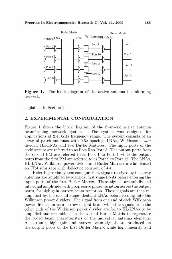
Figure 1. The block diagram of the active antenna beamformingnetwork.
explained in Section 2.
2. EXPERIMENTAL CONFIGURATION
Figure 1 shows the block diagram of the front-end active antennabeamforming network system. The system was designed forapplications at 2.45 GHz frequency range. The system consists of anarray of patch antennas with 0.5λ spacing, LNAs, Wilkinson powerdivider, HL-LNAs and two Butler Matrices. The input ports of thearchitecture are referred to as Port 5 to Port 8. The output ports fromthe second BM are referred to as Port 1 to Port 4 while the outputports from the first BM are referred to as Port 9 to Port 12. The LNAs,HL-LNAs, Wilkinson power divider and Butler Matrices are fabricatedon FR4 substrate with dielectric constant of 4.4.
Referring to the system configuration, signals received by the arrayantennas are amplified by identical first stage LNAs before entering theinput ports of the first Butler Matrix. These signals are subdividedinto equal amplitude with progressive phase variation across the outputports, for high gain-narrow beam reception. These signals are then re-amplified by the second stage identical LNAs before feeding into theWilkinson power dividers. The signal from one end of each Wilkinsonpower divider forms a narrow output beam while the signals from theother ends of the Wilkinson power divider are fed to HL-LNAs to beamplified and recombined in the second Butler Matrix to regeneratethe broad beam characteristics of the individual antenna elements.As a result, high gain and narrow beam signals are produced onthe output ports of the first Butler Matrix while high linearity and
186 Rahim and Gardner
broad beam signals are produced on the output ports of the secondButler Matrix. When compared to a system involving direct, singleended amplification of the individual antenna outputs, this systemoffers enhanced linearity, because the outputs of the four high linearityamplifiers are power combined by the second Butler Matrix. The effecton the system noise figure of losses in the Butler Matrix is reducedwith the introduction of LNAs before each stage of the first ButlerMatrix [17]. The effects of interference, cross coupling and cross talkbetween the circuit elements in this experiment are reduced as themodules are shielded and partitioned with the metal boxes.
In addition to the multi-channel and multi-beam advantagesproduced by the proposed architecture, nulls at different anglecould also be produced for the high linearity-broadbeam signals byalternatively switching off one of the HL-LNAs. This creates anadaptive array antenna system.
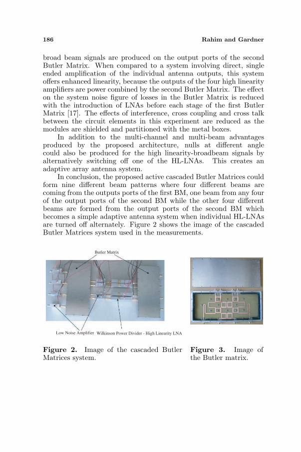
In conclusion, the proposed active cascaded Butler Matrices couldform nine different beam patterns where four different beams arecoming from the outputs ports of the first BM, one beam from any fourof the output ports of the second BM while the other four differentbeams are formed from the output ports of the second BM whichbecomes a simple adaptive antenna system when individual HL-LNAsare turned off alternately. Figure 2 shows the image of the cascadedButler Matrices system used in the measurements.
Butler Matrix
Low Noise Amplifier Wilkinson Power Divider - High Linearity LNA
Figure 2. Image of the cascaded ButlerMatrices system.
Figure 3. Image ofthe Butler matrix.
Progress In Electromagnetics Research C, Vol. 11, 2009 187
3. ELEMENTS OF THE ACTIVE ANTENNABEAMFORMING NETWORK
3.1. Butler Matrix
Smart antennas provide a broad range of ways to improve theperformance of wireless communication systems. Beamforming is oneof the techniques that can be used in the system. RF beamformingtechniques are divided into quasi-optic and circuit type [18]. Thequasi-optic type uses a hybrid arrangement of either a reflector or lensobjective with a feed array. The basic lens based beamforming are theRuze lens and the Rotman lens [19, 20]. The circuit type beamformingtechnique uses couplers, phase shifter and transmission lines in order tocreate the multiple beam networks. Blass Matrix and Butler Matrix aretwo of the examples of the circuit based beamforming network [21, 22].
The Butler Matrix (BM) consists of N input ports with an equalnumber of output ports. A signal introduced at one input producesequal amplitude at all outputs but with a constant phase differencebetween them. As a result, the characteristic of BM can be used tocontrol the direction of the beamforming of an antenna array at acertain angle in space. Figure 3 shows the image of the Butler Matrixas well as the shielded metal box used in this experiment. Absorbingcarbon foams are attached to the sides and the underside of the top lidof the inner metal box in order to reduce internal coupling and externalinterference effects in the shielded metal box.
3.2. Low Noise Amplifier
The SNR at the output ports of the Butler Matrix can be increasedwith the introduction of LNAs. In the measurement, Agilent ATF-55143 amplifier with high dynamic range and low noise figure isused [23]. The chip is designed for use in low cost commercialapplication in the VHF through 6 GHz frequency range. They areduplicated and placed before and after the first stage BM in thecascaded Butler Matrices measurement.
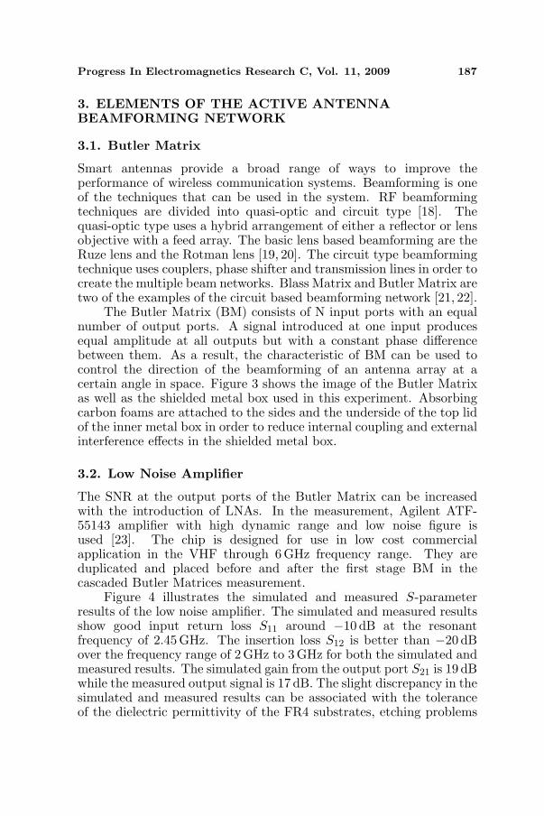
Figure 4 illustrates the simulated and measured S-parameterresults of the low noise amplifier. The simulated and measured resultsshow good input return loss S11 around −10 dB at the resonantfrequency of 2.45 GHz. The insertion loss S12 is better than −20 dBover the frequency range of 2 GHz to 3 GHz for both the simulated andmeasured results. The simulated gain from the output port S21 is 19 dBwhile the measured output signal is 17 dB. The slight discrepancy in thesimulated and measured results can be associated with the toleranceof the dielectric permittivity of the FR4 substrates, etching problems
188 Rahim and Gardner
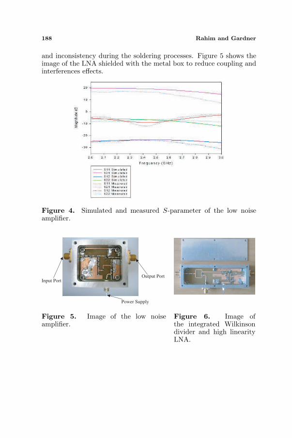
and inconsistency during the soldering processes. Figure 5 shows theimage of the LNA shielded with the metal box to reduce coupling andinterferences effects.
Figure 4. Simulated and measured S-parameter of the low noiseamplifier.
Input Port Output Port
Power Supply
Figure 5. Image of the low noiseamplifier.
Figure 6. Image ofthe integrated Wilkinsondivider and high linearityLNA.
Progress In Electromagnetics Research C, Vol. 11, 2009 189
3.3. Wilkinson Power Divider-high Linearity Low NoiseAmplifier
The Wilkinson Power Divider-High Linearity Low Noise Amplifiermodules (HL-LNAs) are used in the cascading Butler Matrices front-end system. One end of the Wilkinson Power Divider is used to producehigh gain narrowbeam signal from the output port of the first BMwhile the other end of the Wilkinson Power Divider is used to supplythe signal to the High Linearity Low Noise Amplifier to be fed to thesecond BM for recombining. Hence, high linearity broadbeam signalsare produced from the outputs of the second BM.
Figure 6 shows the integrated Wilkinson Power Divider-Highlinearity low noise amplifier element. The element is duplicatedand shielded with a metal box in order to reduce interference. TheWilkinson Power Divider is a lossy network commonly used forpower splitting and combining. The power divider consists of λ/4transmission line, which is equally split. One end of the divider is usedto measure the output from the first BM while the second output portis connected to the HL-LNA. Avago Technology chip (formerly knownas Agilent) model MGA-61563 is used as the HL-LNA [24]. The chipis an economical and easy to use GaAs MMIC amplifier that offersexcellent linearity and noise figure for applications from 0.1GHz to
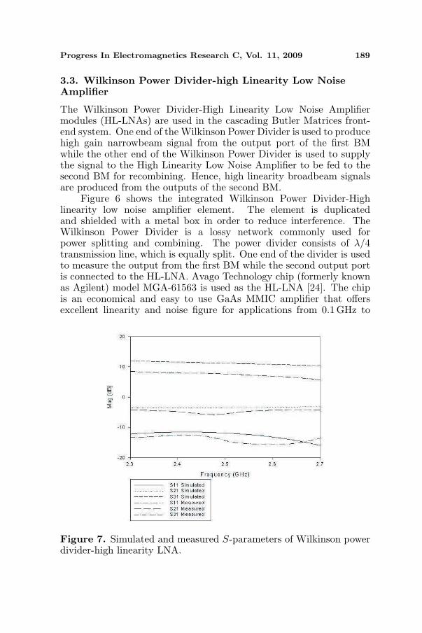
Figure 7. Simulated and measured S-parameters of Wilkinson powerdivider-high linearity LNA.
190 Rahim and Gardner
6GHz. On-chip bias circuitry allows operation from a single +3V or+5V power supply.
Figure 7 shows the simulated and measured S-parameter resultsof the Wilkinson Power Divider-High Linearity Low Noise Amplifier.The simulated and measured results show good return loss S11 below−10 dB from 2 GHz to 3 GHz. The simulated and measured outputsignal from the output port of the Wilkinson Power Divider (S21) isaround −3 dB to −5 dB respectively. The simulated output signalfrom the amplifier, output Port 3 (S31) at 2.45 GHz is 12 dB whilethe measured output signals from the same output port is 9 dB. Thedifference between the simulated and measured results is mainly due toetching process, soldering problems and losses due to FR4 substrates.
3.4. Microstrip Patch Antenna
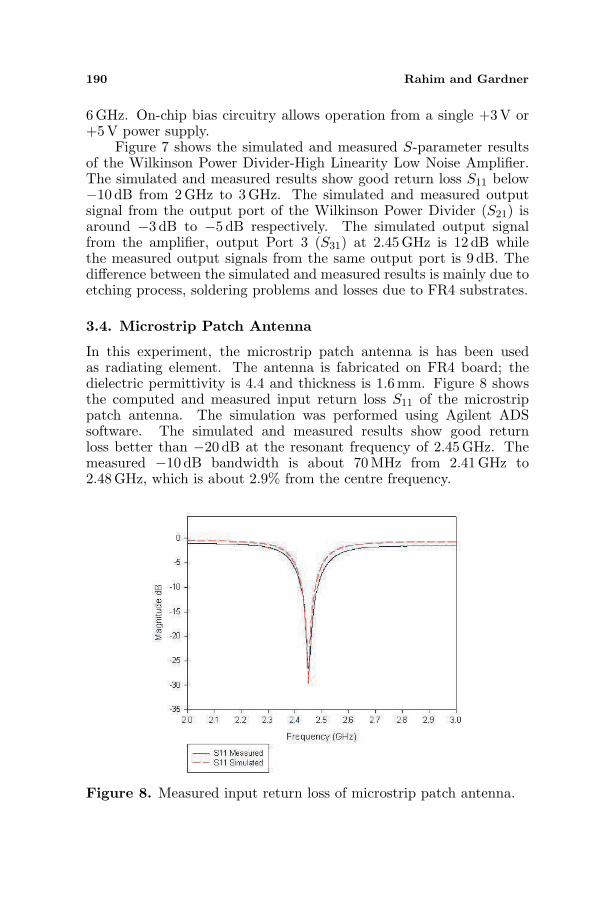
In this experiment, the microstrip patch antenna is has been usedas radiating element. The antenna is fabricated on FR4 board; thedielectric permittivity is 4.4 and thickness is 1.6 mm. Figure 8 showsthe computed and measured input return loss S11 of the microstrippatch antenna. The simulation was performed using Agilent ADSsoftware. The simulated and measured results show good returnloss better than −20 dB at the resonant frequency of 2.45 GHz. Themeasured −10 dB bandwidth is about 70 MHz from 2.41GHz to2.48GHz, which is about 2.9% from the centre frequency.
Figure 8. Measured input return loss of microstrip patch antenna.
Progress In Electromagnetics Research C, Vol. 11, 2009 191
4. RESULTS AND DISCUSSIONS
The radiation pattern measurement was carried out to show thenarrowbeam and broadbeam antenna patterns of the system across180◦ angles. The non-linearity measurement was also undertaken toinvestigate the advantage of the proposed cascaded Butler Matricessystem as well as HL-LNAs.
4.1. Radiation Pattern Measurement
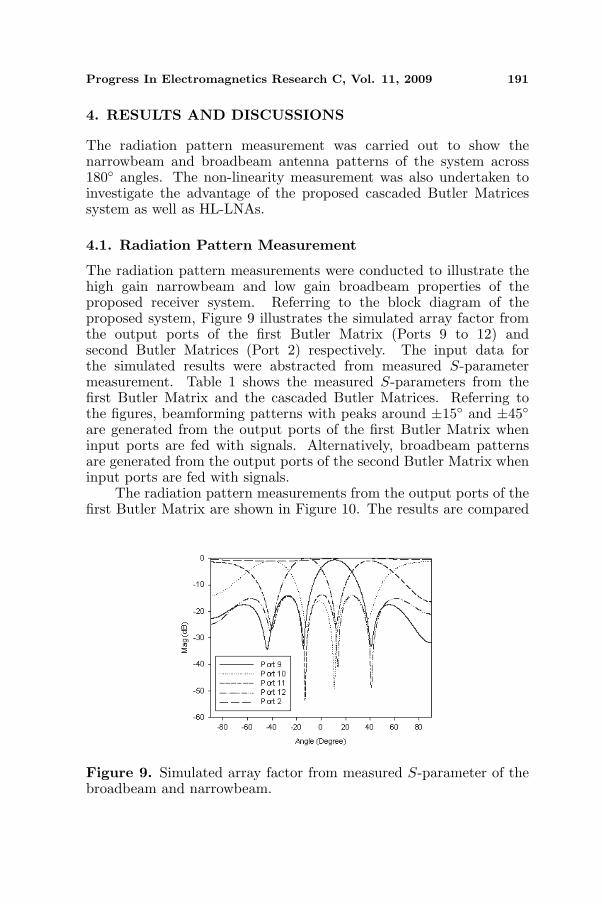
The radiation pattern measurements were conducted to illustrate thehigh gain narrowbeam and low gain broadbeam properties of theproposed receiver system. Referring to the block diagram of theproposed system, Figure 9 illustrates the simulated array factor fromthe output ports of the first Butler Matrix (Ports 9 to 12) andsecond Butler Matrices (Port 2) respectively. The input data forthe simulated results were abstracted from measured S-parametermeasurement. Table 1 shows the measured S-parameters from thefirst Butler Matrix and the cascaded Butler Matrices. Referring tothe figures, beamforming patterns with peaks around ±15◦ and ±45◦are generated from the output ports of the first Butler Matrix wheninput ports are fed with signals. Alternatively, broadbeam patternsare generated from the output ports of the second Butler Matrix wheninput ports are fed with signals.
The radiation pattern measurements from the output ports of thefirst Butler Matrix are shown in Figure 10. The results are compared
Figure 9. Simulated array factor from measured S-parameter of thebroadbeam and narrowbeam.
192 Rahim and Gardner
(a) (b)
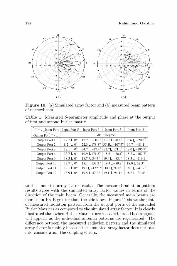
Figure 10. (a) Simulated array factor and (b) measured beam patternof narrowbeam.
Table 1. Measured S-parameter amplitude and phase at the outputof first and second butler matrix.
Input Port
Output Port
Input Port 5 Input Port 6 Input Port 7 Input Port 8
dB Degree
Output Port 1 17.7 0 12.2 −60.7 19.1 −0.8 33.6 −20.5
Output Port 2 8.2 0 22.3 178.8 35.1 −107.3 10.7 −81.1
Output Port 3 18.1 0 34.7 −27.4 22.7 121.1 18.0 −106.7
Output Port 4 33.7 0 10.9 171.3 18.6 −80.1 15.7 −167.7
Output Port 9 18.3 0 18.7 34.7 19.4 −83.4 18.5 −119.1
Output Port 10 17.7 0 18.1 138.3 19.3 −89.9 18.0 52.3
Output Port 11 19.1 0 19.1 −132.3 18.1 92.0 18.0 −41.9
Output Port 12 18.9 0 19.5 47.2 19.1 94.4 18.6 130.4
ο
ο
ο
ο
ο
ο
ο
ο
ο
ο
ο
ο
ο
ο
ο
ο
ο
ο
ο
ο
ο
ο
ο
ο
ο
ο
ο
ο
ο
ο
ο
ο
to the simulated array factor results. The measured radiation patternresults agree with the simulated array factor values in terms of thedirection of the main beam. Generally, the measured main beams aremore than 10 dB greater than the side lobes. Figure 11 shows the plotsof measured radiation pattern from the output ports of the cascadedButler Matrices as compared to the simulated array factor. It is clearlyillustrated than when Butler Matrices are cascaded, broad beam signalswill appear, as the individual antenna patterns are regenerated. Thedifference between the measured radiation pattern and the simulatedarray factor is mainly because the simulated array factor does not takeinto consideration the coupling effects.
Progress In Electromagnetics Research C, Vol. 11, 2009 193
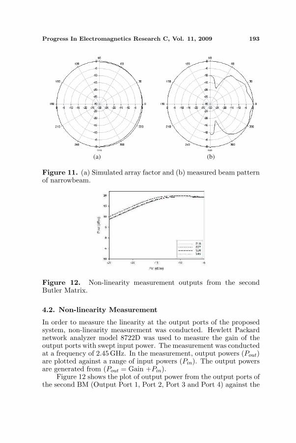
(a) (b)
Figure 11. (a) Simulated array factor and (b) measured beam patternof narrowbeam.
Figure 12. Non-linearity measurement outputs from the secondButler Matrix.
4.2. Non-linearity Measurement
In order to measure the linearity at the output ports of the proposedsystem, non-linearity measurement was conducted. Hewlett Packardnetwork analyzer model 8722D was used to measure the gain of theoutput ports with swept input power. The measurement was conductedat a frequency of 2.45 GHz. In the measurement, output powers (Pout)are plotted against a range of input powers (Pin). The output powersare generated from (Pout = Gain +Pin).
Figure 12 shows the plot of output power from the output ports ofthe second BM (Output Port 1, Port 2, Port 3 and Port 4) against the
194 Rahim and Gardner
(a) (b)
(c) (d)
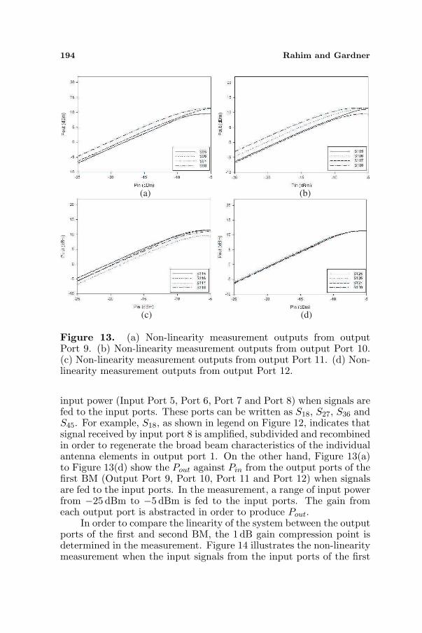
Figure 13. (a) Non-linearity measurement outputs from outputPort 9. (b) Non-linearity measurement outputs from output Port 10.(c) Non-linearity measurement outputs from output Port 11. (d) Non-linearity measurement outputs from output Port 12.
input power (Input Port 5, Port 6, Port 7 and Port 8) when signals arefed to the input ports. These ports can be written as S18, S27, S36 andS45. For example, S18, as shown in legend on Figure 12, indicates thatsignal received by input port 8 is amplified, subdivided and recombinedin order to regenerate the broad beam characteristics of the individualantenna elements in output port 1. On the other hand, Figure 13(a)to Figure 13(d) show the Pout against Pin from the output ports of thefirst BM (Output Port 9, Port 10, Port 11 and Port 12) when signalsare fed to the input ports. In the measurement, a range of input powerfrom −25 dBm to −5 dBm is fed to the input ports. The gain fromeach output port is abstracted in order to produce Pout.
In order to compare the linearity of the system between the outputports of the first and second BM, the 1 dB gain compression point isdetermined in the measurement. Figure 14 illustrates the non-linearitymeasurement when the input signals from the input ports of the first
Progress In Electromagnetics Research C, Vol. 11, 2009 195
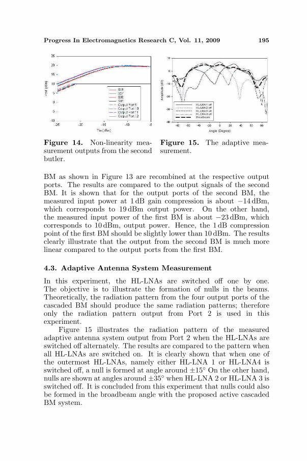
Figure 14. Non-linearity mea-surement outputs from the secondbutler.
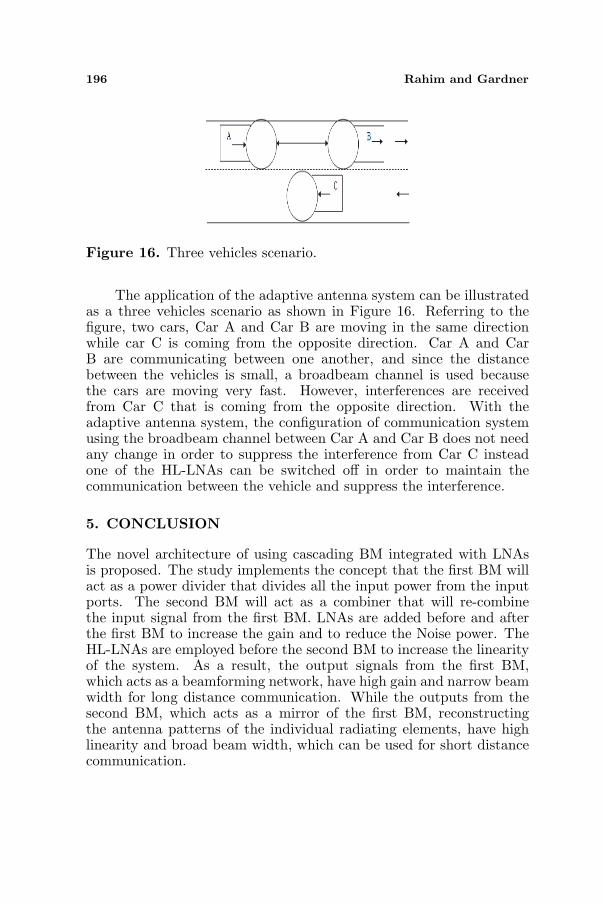
Figure 15. The adaptive mea-surement.
BM as shown in Figure 13 are recombined at the respective outputports. The results are compared to the output signals of the secondBM. It is shown that for the output ports of the second BM, themeasured input power at 1 dB gain compression is about −14 dBm,which corresponds to 19 dBm output power. On the other hand,the measured input power of the first BM is about −23 dBm, whichcorresponds to 10 dBm, output power. Hence, the 1 dB compressionpoint of the first BM should be slightly lower than 10 dBm. The resultsclearly illustrate that the output from the second BM is much morelinear compared to the output ports from the first BM.
4.3. Adaptive Antenna System Measurement
In this experiment, the HL-LNAs are switched off one by one.The objective is to illustrate the formation of nulls in the beams.Theoretically, the radiation pattern from the four output ports of thecascaded BM should produce the same radiation patterns; thereforeonly the radiation pattern output from Port 2 is used in thisexperiment.
Figure 15 illustrates the radiation pattern of the measuredadaptive antenna system output from Port 2 when the HL-LNAs areswitched off alternately. The results are compared to the pattern whenall HL-LNAs are switched on. It is clearly shown that when one ofthe outermost HL-LNAs, namely either HL-LNA 1 or HL-LNA4 isswitched off, a null is formed at angle around ±15◦ On the other hand,nulls are shown at angles around ±35◦ when HL-LNA 2 or HL-LNA 3 isswitched off. It is concluded from this experiment that nulls could alsobe formed in the broadbeam angle with the proposed active cascadedBM system.
196 Rahim and Gardner
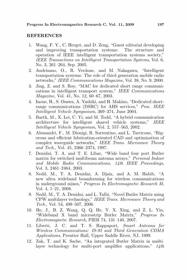
Figure 16. Three vehicles scenario.
The application of the adaptive antenna system can be illustratedas a three vehicles scenario as shown in Figure 16. Referring to thefigure, two cars, Car A and Car B are moving in the same directionwhile car C is coming from the opposite direction. Car A and CarB are communicating between one another, and since the distancebetween the vehicles is small, a broadbeam channel is used becausethe cars are moving very fast. However, interferences are receivedfrom Car C that is coming from the opposite direction. With theadaptive antenna system, the configuration of communication systemusing the broadbeam channel between Car A and Car B does not needany change in order to suppress the interference from Car C insteadone of the HL-LNAs can be switched off in order to maintain thecommunication between the vehicle and suppress the interference.
5. CONCLUSION
The novel architecture of using cascading BM integrated with LNAsis proposed. The study implements the concept that the first BM willact as a power divider that divides all the input power from the inputports. The second BM will act as a combiner that will re-combinethe input signal from the first BM. LNAs are added before and afterthe first BM to increase the gain and to reduce the Noise power. TheHL-LNAs are employed before the second BM to increase the linearityof the system. As a result, the output signals from the first BM,which acts as a beamforming network, have high gain and narrow beamwidth for long distance communication. While the outputs from thesecond BM, which acts as a mirror of the first BM, reconstructingthe antenna patterns of the individual radiating elements, have highlinearity and broad beam width, which can be used for short distancecommunication.
Progress In Electromagnetics Research C, Vol. 11, 2009 197
REFERENCES
1. Wang, F. Y., C. Herget, and D. Zeng, “Guest editorial developingand improving transportation systems: The structure andoperation of IEEE intelligent transportation systems society,”IEEE Transactions on Intelligent Transportation Systems, Vol. 6,No. 3, 261–264, Sep. 2005.
2. Andrisano, O., R. Verdone, and M. Nakagawa, “Intelligenttransportation systems: The role of third generation mobile radionetworks,” IEEE Communications Magazine, Vol. 38, No. 9, 2000.
3. Jing, Z. and S. Roy, “MAC for dedicated short range communi-cations in intelligent transport system,” IEEE CommunicationsMagazine, Vol. 41, No. 12, 60–67, 2003.
4. Inoue, H., S. Osawa, A. Yashiki, and H. Makino, “Dedicated short-range communications (DSRC) for AHS services,” Proc. IEEEIntelligent Vehicle Symposium, 369–374, June 2004.
5. Barth, M., X. Lei, C. Yi, and M. Todd, “A hybrid communicationarchitecture for intelligent shared vehicle systems,” IEEEIntelligent Vehicle Symposium, Vol. 2, 557–563, 2002.
6. Alessandri, F., M. Dionigi, R. Sorrentino, and L. Tarricone, “Rig-orous and efficient fabrication-oriented CAD and optimization ofcomplex waveguide networks,” IEEE Trans. Microwave Theoryand Tech., Vol. 45, 2366–2374, 1997.
7. Denidni, T. A. and T. E. Libar, “Wide band four port Butlermatrix for switched multibeam antenna arrays,” Personal Indoorand Mobile Radio Communications, 14th IEEE Proceedings,Vol. 3, 2461–2464, 2003.
8. Nedil, M., T. A. Denidni, A. Djaiz, and A. M. Habib, “Anew ultra wideband beamforming for wireless communicationsin underground mines,” Progress In Electromagnetic Research M,Vol. 4, 1–21, 2008.
9. Nedil, M., T. A. Denidni, and L. Talbi, “Novel Butler Matrix usingCPW multilayer technology,” IEEE Trans. Microwave Theory andTech., Vol. 54, 499–507, 2006.
10. He, J., B. Z. Wang, Q. Q. He, Y. X. Xing, and Z. L. Yin,“Wideband X band microstrip Butler Matrix,” Progress InElectromagnetic Research, PIER 74, 131–140, 2007.
11. Liberti, J. C. and T. S. Rappaport, Smart Antenna forWireless Communications: IS-95 and Third Generation CDMAApplications, Prentice Hall, Upper Saddle River, NJ, 1999.
12. Zak, T. and K. Sache, “An integrated Butler Matrix in multi-layer technology for multi-port amplifier applications,” 14th
198 Rahim and Gardner
International Conference on Microwaves, Radar and WirelessCommunications, Vol. 1, May 2002.
13. Piovano, P., L. Accatino, A. Angelucci, T. Jones, P. Capece, andM. Votta, “Design and breadboarding of wideband N ×N Butlermatrices for multiport amplifiers,” Microwave Conference/Brazil,SBMO International, Vol. 1, 175–180, 1993.
14. Angelucci, A., P. Audagnotto, P. Corda, and B. Piovano,“Multiport power amplifiers for mobile-radio systems usingmicrostrip Butler matrices,” Antennas and Propagation SocietyInternational Symposium, 1994. AP-S. Digest, Vol. 1, 628–631,Jun. 1994.
15. Sudrez-Fajardo, C., M. Ferrando-Batallur, A. Valero, andV. Rodrigo, “Multiple beam system with circular arrays,”Antennas and Propagation Society International Symposium, 2005IEEE, Vol. 4B, 35–38, Jul. 3–8, 2005.
16. Suarez, C., M. Ferrando-Bataller, and A. Valero-Nogueira,“Pattern synthesis of uniform circular arrays with directiveelements,” Antennas and Propagation Society InternationalSymposium, 2004. IEEE, Vol. 3, 2812–2815, Jun. 20–25, 2004.
17. Nibler, F., High Frequency Circuit Engineering, The Institute ofElectrical Engineering, 1996.
18. Hall, P. S. and S. J. Vetterlein, “Review of radio frequency beam-forming techniques for scanned and multiple beam antennas,” IEEProceeding, Vol. 137, No. 5, 293–303, 1990.
19. Ruze, J., “Wide-angle metal plate optics,” Proc. of the IRE,Vol. 38, No. 1, 53–59, 1950.
20. Rotman, W. and R. Turner, “Wide-angle microwave lens for linesource applications,” IEEE Trans. on Antennas and Applications,Vol. 11, No. 6, 623–632, 1963.
21. Moody, H. J., “The systematic design of the Butler Matrix,” IEEETransactions on Antennas and Propagation, Vol. 12, No. 6, 786–788, 1964.
22. Blass, J., “Multidirectional antenna — A new approach to stackedbeams,” IRE Inter. Convention Record, Vol. 8, 1960.
23. Data Sheet Agilent ATF-55143 Low Noise Enhancement ModePseudomorphic HEMT in a Surface Mount Plastic Package.
24. Data Sheet, Avago Technologies MGA-61563 Current Adjusted,Low Noise Amplifier.