a finite element simulation on creep behavior in welded …€¦ · · 2010-05-04a finite...
TRANSCRIPT
TECHNISCHE MECHANIK, 30, 1-3, (2010), 157 – 168submitted: October 22, 2009
A finite element simulation on creep behavior in welded joint ofchrome-molybdenum steel including interaction between void evolutionand dislocation dynamics
T. Iwamoto, E. Murakami, T. Sawa
This paper deals with a new framework of a numerical method for a prediction of creep behavior in a welded jointwith a chrome-molybdenum steel by including both void evolution and dislocation dynamics. For a creep consiti-tuive equation with void evolution, the model proposed in the past is generalized by vanishing the locally coupledanalysis. A dislocation model with a scalar variable of dislocation density, which the dislocation can be piled upand annihilated, is included into the creep constitutive equation. Interactions between the void and dislocation arenewly considered, as the void becomes an obstacle against the dislocation motion and a dense dislocation fieldbecomes a source and a sink of the void.
1 Introduction
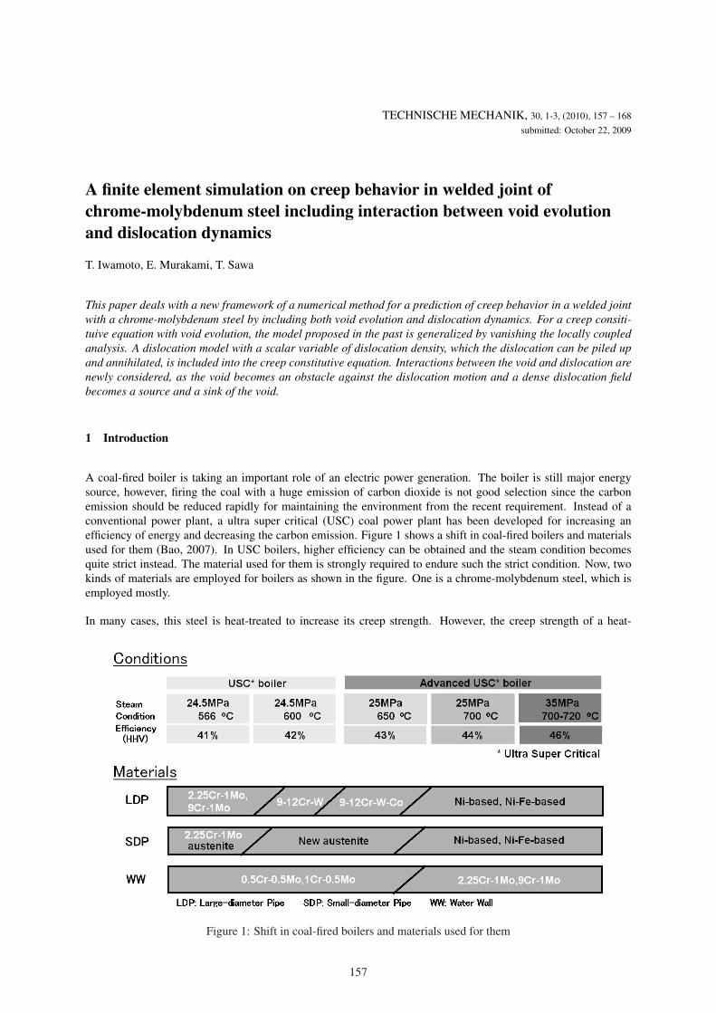
A coal-fired boiler is taking an important role of an electric power generation. The boiler is still major energysource, however, firing the coal with a huge emission of carbon dioxide is not good selection since the carbonemission should be reduced rapidly for maintaining the environment from the recent requirement. Instead of aconventional power plant, a ultra super critical (USC) coal power plant has been developed for increasing anefficiency of energy and decreasing the carbon emission. Figure 1 shows a shift in coal-fired boilers and materialsused for them (Bao, 2007). In USC boilers, higher efficiency can be obtained and the steam condition becomesquite strict instead. The material used for them is strongly required to endure such the strict condition. Now, twokinds of materials are employed for boilers as shown in the figure. One is a chrome-molybdenum steel, which isemployed mostly.
In many cases, this steel is heat-treated to increase its creep strength. However, the creep strength of a heat-
Figure 1: Shift in coal-fired boilers and materials used for them
157

affected zone (HAZ) created after welding at the welded joint of the steel is quite low. Figure 2 (a) shows ahardness distribution through the welded joint (Bao, 2007). As shown in this figure (a), the hardness suddenlydecrease at the HAZ near the interface between the HAZ and the base metal. According to an analogy from thehardness distribution, it is possible that a failure originates from the HAZ near the interface due to decrease ofits creep strength. Figure 2 (b) shows a photograph of a cross-section of a specimen after the creep failure in thewelded joint (Bao, 2007). As shown in this figure, the fracture occurs at the HAZ near the interface. This resultis corresponding to the hardness distribution. This fact is a huge problem for a reliability of the USC coal powerplant. To improve the reliability of USC boilers, an increase of its creep strength might become a key technologyand a prediction of its creep strength is quite essential.
Figure 3 shows micrographs of a cross-section in the HAZ at (a) 10 mm, (b) 40 mm in depth from the surfaceand (c) growth to a crack after a coalescence of voids (Hasegawa and Maeda, 2006). As shown in this figure,a microvoid is nucleated at different locations in the HAZ and the number of voids inside the HAZ becomeslarger as compared with that near the surface. A coalescence of the voids can be observed and this coalescence
(a) (b)Figure 2: (a) Hardness profile through the welded joint and (b) a photograph of a cross-section of a specimen afterthe creep failure in the welded joint of the chrome-molybdenum steel
Figure 3: Micrographs of cross-section in the HAZ at (a) 10 mm in depth, (b) 40 mm in depth from the surfaceand (c) growth to a crack after a coalescence of voids
158

is growing to a larger-scaled crack. This consequent process with the nucleation, the growth and the coalescenceof the microvoid in the HAZ is a main mechanism of the decrease in its creep strength. Therefore, a predictionand a control of a damage due to the creep void evolution is quite essential to prevent a failure of the boilersand increase their lifetime. In order to predict the creep void evolution, Takemasa et al. (1999) proposed that acreep constitutive equation based on the Tvergaad-Needleman model (Tvergaard and Needleman, 1984), whichwas originally developed for the ductile fracture analysis of porous materials by extending the Gurson’s model(Gurson, 1977). They introduced the locally coupled analysis (Lemaitre, 1996). As Lemaitre said in this book,this analysis is effective for brittle and fatigue types of damage. Hence, we have a doubt that this analysis canbe applied for the creep behavior or not. Furthermore, although their FE calculation by using the commercial FEsoftware ABAQUS shows that the creep strain is not localized near the interface between the HAZ and the basemetal, the void fraction calculated on the basis of the computational result is strongly localized there.
Here, a new framework for a numerical analysis of creep behavior including both a void evolution and a dislocationdynamics for a modified 9Cr-1Mo steel welded joint is proposed. First, the creep constitutive model with the voidevolution proposed by Takemasa et al. Takemasa et al. (1999) is generalized by vanishing the locally coupledanalysis. By using the set of parameters appeared in the article (Takemasa et al., 1999), a simulation with the samecondition is performed in order to compare with the computational results obtained by Takemasa et al. (1999).After that, a dislocation model proposed in the past (Mecking and Kocks, 1981; Estrin, 1998) is included into thecreep constitutive equation. In this model, the dislocation can be piled up and annihilated. Interactions betweenthe void and the dislocation are newly considered, as the void becomes an obstacle against the dislocation motionand the dense dislocation leads to the source and sink of the microvoid. All the proposed constitutive equationsare implemented into the commercial software ABAQUS through the user material subroutine UMAT. The newlyproposed model is verified by a comparison with the experimental result. Finally, effects of interactions and thegrain size of HAZ considered here on distribution of a void fraction, a dislocation density and creep strain areexamined.
2 Fundamental theory
In this section, the three different models of the creep potential, the void evolution and the dislocation dynamicsare individually explained. Of course, models for interactions between void and dislocation are described here.
2.1 Gurson’s creep potential
Gurson (1977) originally developed the model for the ductile fracture analysis of porous materials. And then,Tvergaard and Needleman (1984) extended Gurson’s model and the well-known Tvergaad-Needleman model iswidely used in order to solve problems related to the ductile fracture and/or porous materials. Obeying Takemasaet al. (1999), a plastic deformation in their model is automatically replaced to a creep deformation.
First, the total strain rate εij can be decomposed into three parts as
εij = εeij + εt
ij + εcij . (1)
εeij and εt
ij are the elastic and the thermal parts of the strain rate which can be expressed by
εeij = Bijklσij and εt
ij = κij T , (2)
where Bijkl is the elastic compliance tensor, T is a rate of temperature and κij is the thermal expansion tensor.If a thermally-isotropic material is considered, κij becomes the simple form of αT δij , where αT is the thermalexpansion coefficient. On the other hand, εc
ij is the creep strain rate and can be formulated obeying the flow rule as
εcij = λ
∂Φ∂σij
. (3)
Here, the Gurson’s yield function is employed for the creep potential Φ to express the creep deformation with thevoid evolution as
Φ(σij , σ, fv) =32
σ′ijσ′ijσ2
+ 2q1fv cosh(
3q2σm
2σ
)− {
1− (q1fv)2}
= 0, (4)
159
where fv indicates the void volume fraction, σ means the equivalent stress of the fully dense matrix material, σm
is the hydrostatic stress, q1 and q2 are constants. The evolution of the equivalent creep strain in the matrix materialis obtained from the following equivalent irreversible work expression by creep:
(1− fv)σ ˙ε = σij εcij , (5)
where ˙ε means the equivalent creep strain of a matrix material. From equations (3) to (5), εcij can be explicitly
written as
εcij =
(1− fv)σ ˙ε
2σ2e + 3q1q2fvσσm sinh
(3q2σm
2σ
){
3σ′ij + q1q2fvσ sinh(
3q2σm
2σ
)δij
}. (6)
As expressed in equation (4), the creep potential has the nonlinear form against σ and it is hard to obtain an equationfor σ. Instead of a use of equation (4), the following equation should be satisfied during the creep deformation as
Φ = 0, (7)
then we have the following evolution equation for σ as
˙σ =Aij σij + Bfv
2σ2e
σ + 3q1q2fvσm sinh(
3q2σm
2σ
) , (8)
Aij = 3σ′ij + q1q2fvσ sinh(
3q2σm
2σ
)δij and B = 2q1σ
2 cosh(
3q2σm
2σ
)− 2q2
1fvσ2
Since σ is a function of ˙ε, Norton’s power law is frequently employed for the relationship.
2.2 Void evolution
A rate of total void volume fraction can be generally decomposed into three parts as (Tvergaard and Needleman,1984; Takemasa et al., 1999)
fv = fnv + fg
v + f cv . (9)
Here, f cv is the coalescence part of the rate of the void volume fraction and we vanish this term here. fg
v is the rateof void volume fraction concerning with a void growth. Growth of pre-existing or newly-nucleated voids is basedon the law of conservation of mass and is expressed in terms of the void volume fraction:
fgv = (1− fv)εc
kk. (10)
fnv is the nucleation part of the void volume fraction. The nucleation of voids is given by a strain-controlled
relationship (Chu and Needleman, 1980):
fnv =
Fh
SN
√2π
exp{−1
2
(ε − εN
SN
)}˙ε. (11)
The normal distribution of the nucleation strain has a mean value εN and standard deviation SN . Fh is the volumefraction of the nucleated voids, and voids are nucleated only in tension. The function f∗ models the rapid loss ofstress carrying capacity that accompanies void coalescence instead of a use of f c
v . This function is defined in termsof the void volume fraction:
f∗ =
fv for fv ≤ fcr
fcr +1
q1−fcr
fF−fcr(fv − fcr) for fv > fcr
. (12)
In the above relationship, fcr is a critical value of the void volume fraction and fF is the value of void volumefraction at which there is a complete loss of stress carrying capacity in the material. The user-specified parameters
160

fcr and fF model the material failure when f > fcr, due to mechanisms such as micro fracture and void coales-cence. After the substitution of Eqs. (10) and (11) into Eq. (9), the total void volume fraction fv can be calculatedby a time integration of Eq. (9). Then, the above function f∗ is applied for on the basis of the calculated fv .
2.3 Evolution of dislocation density
Mecking and Kocks (1981) proposed the model for a strain-hardening in terms of the dislocation density as
σ0 = MαGb√
ρ, (13)
where M is the Taylor factor, G is the shear modulus, b is the magnitude of the Burger’s vector, ρ is the dislocationdensity and α is a constant. In order to express the strain hardening behavior with the evolution of dislocationdensity by using the above equation, the conventional Norton’s power law is modified as (Estrin and Mecking,1984)
˙ε = A
(σ
σ0
)m
, (14)
where A is a constant and m is the strain rate sensitivity exponent. The form of the equation for the evolutionof the dislocation density makes it possible to include in the model of the metallurgical characteristics as well asinformation on the microstructure of the material. The evolution law of the dislocation density takes into accountof a storage as well as an annihilation of dislocation. The time evolution of ρ in the process of creep deformationis described as Mecking and Kocks (1981), and Estrin (1998)
ρ = M
(1Λb
− kρ
)˙ε, (15)
where Λ is the mean free path of the dislocation. The first term in the bracket on the right hand side of the aboveequation characterizes the processes of storage for dislocations. The second term is related to the annihilationand expresses the thermally activated process of dynamic recovery during the creep deformation. The coefficient kcharacterizes the concurrent dislocation annihilation and represents the thermally activated process by a dislocationcross-slip at low temperature or a dislocation climb at high temperature. The strain rate dependence of k can beexpressed as
k = k0
( ˙ε˙ε0
)− 1`
. (16)
˙ε0 is the reference strain rate as a function of temperature and ` is a constant. In this work, ˙ε0 is dealt with as aconstant.
Λ is given by the average dislocation spacing. In a more general case of a material with a microstructure, Λ can beexpressed as
1Λ
=∑
i
1Λi
, (17)
where the quantities Λi denote the particular values of the mean free path for an individual dislocation storagemechanism. For example, Estrin (1998) employed two kinds of the mean free path as
1Λ
=1Λ1
+1Λ2
=1d
+ β√
ρ, (18)
where, d is the grain size and β is a constant. The first term on the right hand side means effect of grain boundary atthe initial state. The second term represents the effect of the dislocation forest. Both effects are acting as obstaclesfor mobile dislocations.
161

2.4 Models for interactions between void and dislocation
Once dislocation is piling up at obstacles such as a grain boundary, a harder phase, etc., the possibility of anincrease in nuclei of the microvoid might become higher. Hence, it can be assumed that the dislocation evolutionaffects on the void evolution. Lubarda et al. (2004) proposed a mechanism of void growth by dislocation emissionfrom the surface of the void under a shock loading. Their idea is similar to ours and becomes a valuable evidenceto support the assumption described above. This effect can be introduced into the model as the first interactionbetween void and dislocation evolution. The rate of void volume fraction fv can be decomposed into three partswith an exception of the coalescence term as
fv = fgv + fn
v + fDv , (19)
fDv means the effect of a dislocation on the nucleation and the growth of the void. Li et al. (2009) proposed
the framework which consists of the continuum damage mechanics and the dislocation dynamics established byMecking and Kocks (1981), and Estrin (1998) to solve a recovery of mechanical properties after annealing of alinepipe including the recrystallization. Obeying Li et al. (2009), the equation for the damage variable is employedto describe the effect and can be expressed as
fDv = C(1− fv)ρ, (20)
where C is a constant.
On the other hand, the void might become an obstacle for the dislocation motion. Serri and Cherkaoui (2008)introduced the third mean free path and employed the explicit form of the mean free path proposed by Fullman(1953) for the simulation of TRIP steels which contains a hard martensitic phase as the obstacle. The idea can beintroduced into this framework. To describe this effect, the third mean free path Λ3 which indicates an intervalbetween the microvoids is introduced into the equation (18) as
1Λ
=1d
+ β√
ρ +1Λ3
(21)
Obeying Fullman (1953), and Serri and Cherkaoui (2008), Λ3 can be expressed as:
1Λ3
=12e
fv
1− fv, (22)
where e is the average radius of the microvoid.
It is noted that all of fv formulated in this section can be rewritten to f∗ to include the effect of the void coalescence.
3 Computational model and conditions
The above-mentioned constitutive models are implemented into the ABAQUS through a user defined materialsubroutine UMAT based on the implicit time integration. According to the ABAQUS Manual, the time step canbe controlled automatically within a certain range of the time which the user can be defined. Figure 4 shows thecomputational model with FE mesh division and boundary conditions. Creep behavior of the rounded bar specimenwith the nominal stress of 49 MPa at the left end is simulated. The specimen is divided into three regions suchas a base metal, an HAZ and a weld metal. The size of regions and the specimen is written in the figure. Theeight nodes quadratic element is used and the total number of elements is 2325. The FE mesh division becomesfiner near interfaces between each material and the circumferential surface. To keep a flat end during the creepdeformation, a constraint of nodal displacements for the loading direction is introduced at the left side of edge.The material parameters and constants used here are shown in Table 1. These parameters are determined by thereference of articles published in the past (Takemasa et al., 1999; Serri and Cherkaoui, 2008; Li et al., 2009).
4 Validity of user defined subroutine and calculated results including void and dislocation evolution
Figure 5 shows distribution of (a) von Mises equivalent stress and (b) equivalent creep strain at 7595.4 hrs computedby the ABAQUS with the conventional Norton’s law and the established user material subroutine without void
162

Figure 4: Finite element model with boundary conditions
Table 1: Material parameters and constants used here for the modified 9Cr-1Mo steel
@@
Base Metal HAZ Weld Metal @@@@
Base Metal HAZ Weld Metal
E [GPa] 90000 ν 0.28A 8.0 × 10⁻¹⁷ 3.3 × 10⁻²⁰ 1.3 × 10⁻¹⁵ m 4.7 6.7 4.2q1 1.5 q2 1.0fF 0.018 fcr 0.01Fh 0.035 SN 0.01εN 0.03 M 3.06α 0.43 0.33 0.43 b [mm] 2.56 × 10⁻⁷
k0 7.35 8.23 ˙ε0 3.6 × 10³
` 25.0 21.0 22.0 d [mm] 5.0 × 10⁻³
β 3.1 × 10⁻² 3.2 × 10⁻² 5.3 × 10⁻² ρinit [mm−2] 1.0 × 10³
e [mm] 4.0 × 10⁻⁴ C 1.7 × 10⁻⁵
and dislocation evolution. The above-mentioned constitutive equation without effects of dislocation and void isequivalent to the Norton’s law which has already implemented into the ABAQUS. From this figure, the fairlygood agreement can be observed. Thus, the developed UMAT is valid for the further computations with void anddislocation evolution.
(a) (b)
Figure 5: Distribution of (a) von Mises equivalent stress and (b) equivalent creep strain at 7595.4 hrs computed bythe ABAQUS with Norton’s law and developed UMAT without void and dislocation evolution
Figure 6 (a) shows the creep curve obtained by the experiment (Fujii et al., 1998a,b) and computation with variousconstitutive equations. All the computational results are corresponding to the experimental data except for theregion of the acceralating creep. In order to confirm in detail, Fig. 6 (b) shows the magnified figure on the vertical
163

(a) (b)
Figure 6: (a) Creep curves and (b) their curves maginified on the vertical axis, which are obtained by the experimentand computations calculated with considering void, dislocation evolutions and their interactions.
axis of the figure (a). As shown in this figure, it can be said that the computational result is almost corresponding tothe experimental result. However, the difference in the region of the transient creep can be observed. The differencebetween the computational results with a different constitutive equation is clearly observed in this figure. Thus, thecreep curve is affecting on the used constitutive equation slightly. Over 4000 hrs, the difference becomes larger.If only void evolution is considered, the creep strain over 4000 hrs is slightly reduced by a softening effect dueto an existence of void. On the other hand, the creep strain slightly increases over 4000 hrs if only dislocationevolution is considered. Computational results with Norton’s law and the proposed constitutive equation show agood correspondence by a balance between the softening effect due to a void and the hardening effect due to thedislocation evolution. However, both the primary and the tertiary creep stages are not reproduced by the model.This difference will be able to be vanished by a further study on adjusting the material parameter.
Figure 7 shows distribution of void volume fraction computed by two different kinds of constitutive equation suchas (a) Gurson’s model (equivalent to the proposed model without dislocation motions) and (b) the model proposedhere. As shown in this figure, the void is localized slightly-inside from the surface in the HAZ region. Theregion with higher void fraction in the base metal near the interface is developed in our calculation including theinteraction. Takemasa et al. (1999) reported the void volume fraction becomes maximum inside from the surfacenear an interface between the HAZ and the base metal from their calculation based on the locally coupled analysis.However, their result can not be seen in this calculation and our result indicates the position of the maximum voidfraction is located at the center of the HAZ, not near the interface. It can be said that the locally coupled analysiswhich they employed is not suitable and some errors are derived.
(a) (b)Figure 7: Distribution of void volume fraction calculated by considerations of (a) only void evolution, and (b) aninteraction between void and dislocation evolution at 4820 hrs
164
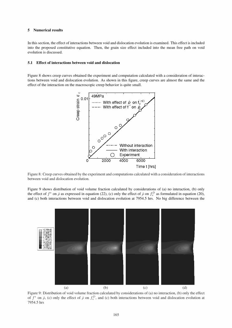
5 Numerical results
In this section, the effect of interactions between void and dislocation evolution is examined. This effect is includedinto the proposed constitutive equation. Then, the grain size effect included into the mean free path on voidevolution is discussed.
5.1 Effect of interactions between void and dislocation
Figure 8 shows creep curves obtained the experiment and computation calculated with a consideration of interac-tions between void and dislocation evolution. As shown in this figure, creep curves are almost the same and theeffect of the interaction on the macroscopic creep behavior is quite small.
Figure 8: Creep curves obtained by the experiment and computations calculated with a consideration of interactionsbetween void and dislocation evolution.
Figure 9 shows distribution of void volume fraction calculated by considerations of (a) no interaction, (b) onlythe effect of f∗ on ρ as expressed in equation (22), (c) only the effect of ρ on fD
v as formulated in equation (20),and (c) both interactions between void and dislocation evolution at 7954.5 hrs. No big difference between the
(a) (b) (c) (d)Figure 9: Distribution of void volume fraction calculated by considerations of (a) no interaction, (b) only the effectof f∗ on ρ, (c) only the effect of ρ on fD
v , and (c) both interactions between void and dislocation evolution at7954.5 hrs
165

(a) (b) (c) (d)Figure 10: Distribution of dislocation density calculated by considerations of (a) no interaction, (b) only the effectof f∗ on ρ, (c) only the effect of ρ on fD
v , and (c) both interactions between void and dislocation evolution at7954.5 hrs
computational results can be observed, however, the maximum value becomes different. From this figure (b), themaximum value is higher than the case without any interactions because the dislocation is dealt with as a sourceof void fraction. The shape of distribution as shown in the figure (d) is a kind of sum of distribution as shown inthe figures (b) and (c). Mixed feature can be seen as the distribution becomes similar in cases with considerationsof no interaction and both interactions.
Figure 10 shows distribution of the dislocation density calculated by considerations of (a) no interaction, (b) onlythe effect of f∗ on ρ, (c) only the effect of ρ on fD
v , and (c) both interactions between void and dislocation evolutionat 7954.5 hrs. As shown in this figure, a change between these distribution can be observed only in the HAZ region.Especially, the size and the value of the region with higher void fraction on the distribution become different whenthe type of interactions are changed. If the effect of f∗ on ρ is only considered, the lower value of the dislocationdensity can be observed there. On the contrary, the similar value of the dislocation density can be observed as thecase without any interactions if the effect of ρ on fD
v is only included. Mixed effect of the interaction is appearedwhen both interactions are considered. The size of the region, where the distribution is changed, becomes smallerthan the case without the effect of interactions.
5.2 Effect of grain size
Figure 11 shows creep curves obtained by the experiment and the computation in case of two different grain sizesin 5 µm and 10 µm. As can be seen, the creep curve becomes lower and the material becomes softener against theconstant loading when the grain size is larger. As formulated in equation (21), a coarser grain induces the reducedrate of dislocation density. As the result, the softening behavior as shown in this figure is occurred.
Figure 12 shows distribution of void volume fraction at 7595.4 hrs calculated in case of (a) original d as shown inTable 1 and (b) twice of original d. The maximum value of the void fraction is focused upon. The maximum valuedecreases as the coarse grain is used. At a local region, the void fraction can be suppressed by a use of a coarsergrain. This means the grain boundary effect of the void evolution can be implicitly expressed by the proposedmodel. Abe et al. (2007) reported that a fine-grained zone is produced in the HAZ of welded joints during heatcycle of welding, which accelerates microstructure evolution and damage development during creep at elevatedtemperature. This is called Type IV creep fracture. The results show a possibility of a prediction for the type IVcreep fracture because of the increase in the void volume fraction with a smaller grain size.
Grain boundary diffusion and precipitates has a strong effect on the void evolution (Riedel, 1987; Khaleel et al.,2001). In near future, these effects will be included for a further precise model.
166

Figure 11: Creep curves obtained by the experiment and computations with two cases of grain size d
(a) (b)Figure 12: Distribution of void volume fraction at 7595.4 hrs calculated in the case of (a) original d as shown inTable 1 and (b) twice of original d
6 Summary
In this research work, a new framework for a numerical analysis of creep behavior including both a void evolutionand a dislocation dynamics for a chrome-molybdenum steel welded joint was proposed. First, the creep constitutivemodel with the void evolution proposed by Takemasa et al. Takemasa et al. (1999) was generalized by vanishingthe locally coupled analysis. By using the set of parameters appeared in the article (Takemasa et al., 1999), asimulation with the same condition was performed in order to compare with the computational results obtainedby Takemasa et al. (1999). After that, a dislocation model, which the piled-up and annihilation are considered,proposed in the past (Mecking and Kocks, 1981; Estrin, 1998) was included into the creep constitutive equation.Interactions between the void and the dislocation were newly considered, as the void becomes an obstacle againstthe dislocation motion and the dense dislocation leads to the source and sink of the microvoid. All the proposedconstitutive equations were implemented into the commercial software ABAQUS through the user material sub-routine UMAT. The newly proposed model was verified by a comparison with the experimental result. Finally,effects of interactions and the grain size of HAZ considered here on distribution of a void fraction, a dislocationdensity and creep strain were examined.
Acknowledgement
Financial support from Kure Research Laboratory, Babcock-Hitachi K. K. is gratefully acknowledged. TheABAQUS program was provided under academic license by Dassault Systemes Simulia Corp., Providence, RI.
References
Abe, F.; Tabuchi, M.; Kondo, M.; Tsukamoto, S.: Suppression of type IV fracture and improvement of creepstrength of 9Cr steel welded joints by boron addition. Int. J. Press. Ves. Pip., 84, (2007), 44 – 52.
167

Bao, G.: Development of high strength heat resistant materials and welding technology for 650 - 700 ◦C USCboilers. In: Proc. VGB-TEMPES Technical Meeting, Tokyo (2007).
Chu, C. C.; Needleman, A.: Void nucleation effects in biaxially stretched sheets. Trans. ASME, J. Engng. Mater.Technol., 102, (1980), 249 – 256.
Estrin, Y.: Dislocation theory based constitutive modelling : foundations and appliations. J. Mater. Proc. Technol.,80-81, (1998), 33 – 39.
Estrin, Y.; Mecking, H.: A unified phenomenological description of work hardening and creep based on one-parameter models. Acta Metall., 32, (1984), 57 – 70.
Fujii, K.; Murao, S.; Tomita, A.; Saito, K.: Residual life evaluation of thermal power plant (RET) project - Part1: Introduction to residual life assessment techniques and phase I of RET project. J. Therm. Nucl. Power, Jpn.,498, (1998a), 1 – 17, (in Japanese).
Fujii, K.; Murao, S.; Tomita, A.; Saito, K.: Residual life evaluation of thermal power plants (RET) project - Part2: Phase II of RET project. J. Therm. Nucl. Power, Jpn., 499, (1998b), 27 – 50, (in Japanese).
Fullman, R. L.: Measurement of particle sizes in opaque bodies. Trans. AIME, 197, (1953), 447 – 457.
Gurson, A. L.: Continuum theory of ductile rupture by void nucleation and growth - Part I: Yield criteria and flowrules for porous ductile media. Trans. ASME, J. Engng. Mater. Technol., 99, (1977), 2 – 17.
Hasegawa, S.; Maeda, Y.: Study on a creep analysis of welded part in a large-diameter piping. Tech. Rep. 76,Hokkaido Electric Power Corp. (2006), (in Japanese).
Khaleel, M. A.; Zbib, H. M.; Nyberg, E.: Constitutive modeling of deformation and damage in superplasticmaterials. Int. J. Plast., 17, (2001), 277 – 296.
Lemaitre, J.: A course on damage mechanics. Springer-Verlag, Berlin (1996).
Li, H.; J., L.; Dean, T. A.; Wen, S. W.; Bannister, A. C.: Modelling mechanical property recovery of a linepipesteel in annealing process. Int. J. Plast., 25, (2009), 1049 – 1065.
Lubarda, V. A.; Schneider, M. S.; Kalantar, D. H.; Remington, B. A.; Meyers, M. A.: Void growth by dislocationemission. Acta Mater., 52, (2004), 1397 – 1408.
Mecking, H.; Kocks, U. F.: Kinetics of flow and strain-hardening. Acta Metall., 29, (1981), 1865 – 1875.
Riedel, H.: Fracture at high temperature. Springer-Verlag, Berlin (1987).
Serri, J.; Cherkaoui, M.: Constitutive modeling and finite element analysis of the formability of TRIP steels. Trans.ASME, J. Engng. Mater. Technol., 130, (2008), 031009.
Takemasa, F.; Suzuki, A.; Ito, K.: Creep damage analysis using the Gurson model on welded joints of mod.9Cr-1Mo steel. In: Trans. 15th Int. Conf. on Struct. Mech. in Reactor Technol., vol. X, pages 157 – 164 (1999).
Tvergaard, V.; Needleman, A.: Analysis of the cup-cone fracture in a round tensile bar. Acta Metall., 32, (1984),157 – 169.
Addresses: Assoc. Prof. Dr. Eng. Takeshi Iwamoto, Graduate School of Engineering, Hiroshima University, 1-4-1Kagamiyama, Higashi-Hiroshima, 739-8527 Japan; Mr. Eiji Murakami, Kure Research Laboratory, Babcock-Hitachi K. K., 5-3 Takara-machi, Kure, Hiroshima, 737-0029 Japan; Prof. Dr. Eng. Toshiyuki Sawa, GraduateSchool of Engineering, Hiroshima University, 1-4-1 Kagamiyama, Higashi-Hiroshima, 739-8527 Japan.email: [email protected]; [email protected]; [email protected] .
168