a new synthetic strategy for low-dimensional compounds - diva portal
TRANSCRIPT

1
A new synthetic strategy for low-dimensional compounds
~ Lone pair cations and alkaline earth spacers ~
Rie Takagi Fredrickson
Department of Physical, Inorganic, and Structral Chemistry
Stockholm University
2008

2
Doctoral dissertation 2008
Department of Physical, Inorganic, and Structural Chemistry
Stockholm University
SE-106 91 Stockholm
Sweden
Faculty opponent:
Prof. Lars Kloo
Inorganic Chemistry, KTH
100 44 Stockholm, Sweden
Evaluation committee:
Prof. Margareta Sundberg, FOOS kemi, Stockholm University
Docent Per-Olov Käll, IFM, Linköping University
Docent Torbjörn Gustafsson, Materialkemi, Uppsala University
Substitute committee:
Prof. Stefan Csillag, Nuclear Physics, Stockholm University
© Rie Takagi Fredrickson, Stockholm 2008
ISSN 978-91-7155-538-0 pp. 1 to 58
Printed in Sweden by US-AB, Stockholm 2008
Distributor: FOOS/Inorganic chemistry

3
Dedicated to K. Kameda.
恩師 亀田和久氏に捧ぐ

4

5
Abstract
Complex transition metal oxyhalides containing a lone pair element, such as
tellurium (IV), form an attractive research field because there is a high probability of finding
new low-dimensionally arranged compounds and, particularly, low-dimensionally arranged
transition metal substructures, leading to interesting physical properties. Tellurium (IV) can
drive the formation of many unusual structures because of its stereochemically active lone
pair of electrons, E. It commonly takes a coordination of three or four oxygen atoms to form
either a TeO3E square pyramid or a TeO3+1E trigonal bipyramid. These lone pairs are very
important players involved in lowering the dimensionality of crystal structures. Previous
studies in transition metal tellurium (IV) oxohalide quarternary systems revealed a family of
compounds, many of which exhibit interesting properties e.g. magnetic frustration. The
unique point of this thesis is to employ alkaline earth elements (AE) to augment this ability of
lone pair elements to lower the dimensionality of the transition metal arrangements. By this
double usage of “chemical scissors” (a lone pair element used in conjunction with alkaline
earth elements) we obtained new types of low-dimensionally arranged compounds.
This thesis is focused on the syntheses and characterization of a series of compounds
in the pentanary (five-component) system AE-TeIV-TM-O-X (AE=alkaline earth metal,
TM=transition metal and X=halogen), in which nine new compounds were found. The crystal
structures of each of these compounds were determined by the single crystal X-ray diffraction
data.

6
List of papers This doctoral thesis is based on the results in the following papers: 1) Rie Takagi and Mats Johnsson Ca2CuTe4O10Cl2, a new synthetic tellurium(IV) oxochloride Acta Cryst. (2005). C61, i106-i108. 2) Rie Takagi, Mats Johnsson, Reinhard K. Kremer, and Peter Lemmens Crystal structure and magnetic properties of the coupled spin dimer compound SrCu2(TeO3)2Cl2 J. of Solid State Chemistry. (2006). 179, 3763-3767. 3) Rie Takagi and Mats Johnsson Sr2Cu2TeO6Br2: Honeycomb layers of Cu(II) ions Acta Cryst. (2006). C62, i38-i40. 4) Rie Takagi, Daisy Torino Hjelmqvist and Mats Johnsson The solid solution Co3.6Mg1.4Cl2(TeO3)4 Acta Cryst. (2007). E63, i146-i147. 5) Rie Fredrickson Takagi, Mats Johnsson and Sven Lidin Single crystal x-ray study of Ba2Cu2Te4O11Br2 and its incommensurate modulated superstructure companion Chemistry – A European Journal (2007). accepted. 6) Rie Fredrickson Takagi, Daisy Torino Hjelmqvist, Mats Johnsson and Sven Lidin Helical chains of [MO5Cl] octahedra – Three compounds in the new family AEM2Te3O8Cl2 (AE=Ca, Sr and M=Co, Ni) Solid State Sciences. (2007). submitted. Papers 1 to 4 are reprinted with the permission from the publishers.

7
Additional publications not included in this thesis: 7) Rie Takagi, Mats Johnsson, Reinhard K. Kremer, Vladimir Gnezdilov, and Peter Lemmens Investigation of the novel oxohalogenide Cu4Te5O12Cl4 with Cu(II) tetrahedra Physical Review B. (2006). 1098-0121/2006/74(1)/014413(8). 8) Rie Takagi, Fabienne Duc and Mats Johnsson Crystal structure of MoCu3TeO7Cl2.xH2O Acta Cryst. (2006). C62, i16-i18. 9) R. Valenti, T. Saha-Dasgupta, H.O. Jeschke, B Rahaman, H.Rosner, P. Lemmens,
R.Takagi and M. Johnsson Comparative investigation of the coupled-tetrahedra quantum spin systems
Cu2Te2O5X2, X=Cl,Br and Cu4Te5O12Cl4 Physica C. (2007). 460-462, 462-463.

8

9
Contents 1 Introduction ................................................................................................ 10
1.1 Aim and scope........................................................................................................... 10 1.2 Structure concepts ..................................................................................................... 11
1.2.1 Lone pair elements ..................................................................................... 11 1.2.2 Alkaline earth elements.............................................................................. 15
1.3 What is low dimensionality? ..................................................................................... 20 1.4 Magnetic properties of low dimensional compounds ............................................... 21
2 Synthesis and methodology........................................................................ 25
2.1 Preparation ................................................................................................................ 25 2.2 Characterization ........................................................................................................ 28
2.2.1 Single crystal X-ray data collection and structural refinement .................. 28 2.2.2 Compositional characterization.................................................................. 30 2.2.3 Powder X-ray diffraction ........................................................................... 30
2.3 Bond Valence Sum calculations................................................................................ 30 3 Results and Discussion ............................................................................... 33
3.1 Structures of compounds synthesised within the scope of this thesis ....................... 37 3.1.1 Copper compounds..................................................................................... 37 3.1.2 Cobalt and nickel compounds .................................................................... 44
3.2 Features of the layered compounds........................................................................... 46 3.3 Magnetic susceptibility measurements...................................................................... 47
4 Summary ..................................................................................................... 49 Acknowledgements............................................................................................ 52 References .......................................................................................................... 54 Papers I - VI

10
1 Introduction
1.1 Aim and scope
During last few decades, several structural studies of metal oxohalides have been
performed. Compounds containing metals, especially transition metal oxohalides, are a
fascinating research field as they may exhibit interesting magnetic or other physical properties
that sometimes even require new theoretical explanations.
Some properties require strict structural arrangements, for example high-temperature
superconductivity is phenomenologically coupled to two-dimensional layered arrangements
and antiferromagnetic frustration requires specific transition metal arrangements such as one
dimensional chains. Those structures that have two- or one-dimensional arrangements are
called low dimensional compounds.
We studied low dimensional compounds in the M-TM-O-X system (M: lone pair
element such as TeIV, TM: transition metal, X: halogen) using a structural strategy: We use
TeIV because of its stereochemically active lone pair of electrons. The confluence of such lone
pairs and halogens is often observed in this type of compound, and this M-X combination can
be implemented as “chemical scissors” to cut down dimensionality. A number of such
compounds have been studied previously, Cu2Te2O5X2 (X=Cl, Br) [Johnsson et al., 2000],
Co5(TeO3)4X2 (X=Cl, Br) [Becker et al., 2006], Ni5(TeO3)4X2 (X=Cl, Br) [Johnsson et al.,
2003].
Alkaline earth elements (AE), especially the heavier elements Sr or Ba, are known for
their flexible coordination numbers. The AE are non-magnetic in character which means that
if the AE forms their own building units, such as a two dimensional layers, they will work as
spacers between magnetic species. Previously described compounds of this type are
Ba2Co(SeO3)2Cl2 [Johnston & Harrison, 2002], Ba2Cu4Te4O11Cl4 and BaCu2(TeO3)2Cl2
[Feger & Kolis, 1997]. This AE-M-TM-O-X system is very attractive because of the wide
variety of new compounds it offers and for the original structures such compounds exhibit.
The aim of this thesis is to introduce alkaline earth elements into the M-TM-O-X system to
obtain novel inorganic low dimensionally arranged compounds and test our structural strategy.

11
1.2 Structure concepts
There are not so many inorganic compounds composed of five different elements.
Here I describe the structural concepts of this work and why it was interesting to synthesize
compounds of five individual elements including a transition metal, an alkaline earth element,
a lone pair element, oxygen and a halogen.
1.2.1 Lone pair elements
In the early 19th century, Lewis proposed the idea of chemical bonds consisting of
shared pairs of electrons [Lewis, 1916]. This bonding pair model was used to develop two
important key concepts of Pauling’s valence bond (VB) theory during the period 1928-1930.
This original form of VB theory considered only the σ-bond electron pairs to contribute to
the steric effects of bonding. At this stage, the non-bonding electron pairs were not discussed.
However, it was soon realized that molecular models rationalized the experimentally observed
geometries of molecules much better if lone pair electrons were considered. Sidgwick and
Powell assumed that the lone pairs and bonding pairs are equally important and that they
arrange to minimize interelectron repulsion [Sidgwick, 1940]. Later, Gillespie and Nyholm
suggested that the repulsion between electron pairs decreases in the order: lone pair – lone
pair > lone pair – bonding pair > bonding pair – bonding pair, so that the lone pairs were
considered as larger than the bonding pairs [Gillespie, 1957]. Several unresolved questions
remained: how big are lone pairs, and are they always stereochemically active?
In the beginning of 1970’s, the stereochemical properties of the lone pairs, E, of so-
called ns2 elements (M = PbII, SbIII, BiIII, TeIV…) were studied by Andersson and Åström. The
lone pair elements are found among the cations of the groups 13 to 18 in the periodic table,
conf. Figure 1.1. They highlighted the fact that the lone pair volume in oxides, fluorides or
oxofluorides is of the same size as oxygen or fluorine anions [Åström & Andersson, 1971;
Andersson & Åström, 1972; Galy, 1972; Andersson et. al., 1973; Galy et. al., 1975]. They
also showed that the lone pair electrons are instrumental in the stereochemistry of the
structure. The distances between the atomic nucleus of the lone pair element, M, and the
centre of the sphere of influence of the lone pairs, Es, were calculated from their crystal
structures by positioning the lone pair at the position indicated by “missing” cations. The
resulting M – Es distances for each lone pair element are listed in Figure 1.2.

12
Figure 1.1: The lone pair cations (orange) are shown among the cations of groups 13 to 18 of the p-
block elements in the periodic system.
Figure 1.2: Calculated M - Es distances (Å), where M is the lone pair element and Es is the centre of
the sphere of influence of the M cation’s lone pair.
Later on, the crystal chemistry of the trivalent oxidation state of the group 15
elements was studied in MX3 compounds (M = N, P, As, Sb, Bi and X = F, Cl, Br, I) [Galy &
Enjalbert, 1982], revealing again the reality of the E stereoactivity. The degree of localization
of the electron pairs was modelled by introducing a new parameter, the centroid of the lone
pair, Ec. Ec is a value calculated using quantum mechanical theory [Schmiedekamp et al.,

13
1979] while Es is the empirical value determined from known structures of compounds. The
schematic model of the M, Es and Ec relationships between is shown in Figure 1.3. They
proposed the following rules [Galy et al., 2003]:
• When the nucleus is smaller, the electron pair is closer to the M nucleus and the
distances between M and its ligands, M – X of MX3, are longer.
• The lone pair, E, occupies exactly the position of an oxygen in the pentavalent
analogue of these compounds e.g. PIIIECl3 and PVOCl3.
Another trend obtained in this work is that as we move to less electronegative
elements (e.g. from NIII to BiIII) the effective M – Es distance decreases. Furthermore the lone
pair becomes more stereochemically active when the M – Es distance increases.
Figure 1.3: Schematic model of the lone pair atom M (pink) of Galy and Enjalbert (1982). The lone
pair of the atom M is represented as a dark grey sphere with its centroid at the point Ec. The lone
pair influence region is shown as a light grey sphere; Es is the center of that sphere.
• Lone pair on TeIV atom
In the compounds synthesised and described in this work, tellurium (IV) was
selected as the lone-pair cation. One reason for this choice is that TeO2 is relatively easy to
handle during synthetic work, being less hygroscopic than e.g. SeO2. This is important
because easier and quicker sample production gives more possibilities for finding novel
compounds, one of the aims of this project. There is a further reason from the structural point
of view. When tellurium is in the oxidation state four (TeIV) the lone pair is normally
stereochemically active. This fact is illustrated by the asymmetric coordination polyhedra
seen in the crystal structures of TeIV compounds. This is not always true for lone pair

14
elements. The lone pair of BiIII is quite often stereochemically inactive. Further, TeIV shows a
stronger preference than transition metals (TM) for bonding to oxygen atoms over halogen
anions, so its inclusion in a TeIV-TM-O-X compound leads to the division of the structure into
two parts: a Te-O part and TM-O or TM-OX part. This leads to the formation of structures
with low (two- or one-) dimensional networks.
The TeIV ion is able to coordinate 3 to 6 ligands [Shannon&Prewitt, 1969; Shannon,
1976], and most commonly it has a 3 or 3+1 coordination; the latter notation means three
short (Te – O distance at 1.8 ~ 2.0 Å) and one long (around 2.4 Å) bond. When the
stereochemically active lone pair electrons are taken into account these coordination
polyhedra become TeO3E tetrahedra or TeO3+1E trigonal bipyramids, see Figure 1.4.
Figure 1.4: The two classical coordination types around TeIV cations (pink). a) TeO3 trigonal
pyramidal coordination, which together with the lone pair E forms a TeO3E tetrahedron. b) TeO3+1
see-saw coordination forming a TeO3+1E trigonal bipyramid. O atoms: red, the lone pair influence
regions, Es: gray spheres. From now on, we will use black spheres as a diagrammatic
representation of lone pairs.
The models introduced by Galy (1975) generally yield a longer Te–Es distance when
TeIV is 3-coordinate compared to the case of 3+1 coordination; the corresponding distances
are 1.19 ~ 1.42 Å and 1.08 ~ 1.29 Å respectively. In the compounds in this work we will, for
simplicity, assume a Te-Es distance of 1.25 Å, the average distance found by Galy.

15
1.2.2 Alkaline earth elements
What is new in this work is the use of alkaline earth elements (AE = Mg, Ca, Sr and
Ba) in the TeIV-TM-O-X system (TM = CoII, NiII and CuII, X = Cl and Br). AE have classical
but flexible coodination and they may be chalcophilic and/or halophilic depending on their
sizes. When the AE forms irregular coordination polyhedra e.g. [AEOv], [AEXw] or
[AEOyXz], their polyhedra tend to link together to form larger units, such as chains or layers.
These AE building units block or reduce the dimensionality of the transition metal
oxide/halide network and this leads to the possibility of finding interesting physical properties
such as antiferromagnetism or magnetic frustration. We used this AE-driven dimensionality
reduction as one of our structural strategies to find novel low-dimensional compounds in this
work.
• Example of a 1D AE column
According to the inorganic database, only a handful of compounds are known that
include an AE element in metal oxohalide systems. One example, in which Ba atoms form a
one dimensional column, is the Ba9Cu7O15Cl2 structure [Kipka and Mueller-Buschbaum,
1976a] with a rather interesting combination of units, see Figure 1.5. One of the units is a
Ba3O15 polyhedra ring (A) formed by connecting three BaO6 irregular polyhedra. Each Ba-Ba
distance in the triangular arrangement is 4.26 Å. Another Ba unit forms a [BaO4]3[CuO2]3 ring
(B) with three BaO6 hexagons and three CuO4 squares connected by edge sharing. Those two
distinctive Ba units are connected in the sequence ABAB… to form a one dimensional
column along the [001] direction that has encloses enough volume to hold Cl atoms inside.
Because of this Ba column arrangement, magnetic interactions between Cu cations are limited
to occur within Cu6O12 rings. The Cu building blocks are separated.

16
Figure 1.5: There are two distinctive Ba arrangements in the Ba9Cu7O15Cl2 structure. (a) BaO6
hexagons connects with CuO4 square planes by edge sharing to form the [BaO4]3[CuO2]3 ring (B).
(b) Ba atoms form a Ba3O15 unit (A) formed by three BaO6 irregular polyhedra. (c) The two Ba
arrangments connect in the sequence ABAB… to form a one dimensional column along the [001]
direction. (d) Each CuO4 square (blue) is a fragment of a Cu6O12 ring.
• Example of a 2D AE layer
As an example of a two dimensional arrangement, a bi-layered Ba coordination with
a combination of oxygen and halide anions can be seen in the Ba2Cu3O4X2 (X=Cl and Br)
structure [Kipka & Mueller-Buschbaum, 1976b; Kipka & Mueller-Buschbaum, 1976c]. A
central Ba atom bonds to eight neighbouring atoms: four O and four X atoms at the distances
2.74 Å and 3.14 Å respectively, to form a square antiprismatic [BaO4Cl4] polyhedron (Figure

17
1.6). The [BaO4Cl4] polyhedra are connected through the halides to form a [BaO2X] n bilayer
in the (110) plane.
Figure 1.6: (a) Ba atomic arrangement in the Ba2Cu3O4X2 (X=Cl and Br) structure. Each Ba atom
takes a coordination with four O and four X atoms to form a [BaO4X4] polyhedron. (b) View of the
[BaO2X] n zig-zag layer along the [010] direction. (c) The [BaO2X] n zig-zag layer formed in the (001)
plane.
When the Ba2Cu3O4X2 (X=Cl, Br) structure is compared to that of Ba2Cu2Te4O11Br2,
which has a complex layered arrangement, it can be seen that their layers exhibit a common
Ba-Cu-O building unit, as shown in Figure 1.7. In this unit the Ba atom connects to four O
atoms in a square plane at distances of 2.74 Å (Cl) and 2.79 Å (Br) in the Ba2Cu3O4X2
structure, and a little longer, between 2.87 to 2.96 Å, in the Ba2Cu2Te4O11Br2 structure. Two
of the O atoms are shared with the neighbouring Cu atoms at a distance of approximately 1.95
Å for the three compounds, and these Ba-O-Cu units form [BaCuO4]n chains in the layer.

18
a) b)
c) Figure 1.7: (a) The [BaCuOCl] layer in the compound Ba2Cu3O4Cl2. Ba atoms (yellow), Cu atoms
(light blue), O atoms (red), Cl atoms (light green). The common [BaCuO4]n chain arrangement is
indicated with a black box. (b) The [BaCuO] layer from the Ba2Cu2Te4O11Br2 compound. (c) The
[BaCuO4]n chain is shown.
• Example of a 3D AE cage network
Examples of alkaline earth 3D networks are mainly found in compounds with Sr or Ba
atoms. A Ba cage in the Ba44Cu45O87Cl4 compound [Kipka & Mueller-Buschbaum, 1977] is
formed by edge-sharing of two hexagonal faces and 24 triangles. The Ba atoms are separated
by the distances of 3.9 to 4.3 Å. This Ba20 cage is connected to the six nearest neighbouring
cages by face sharing to form a three dimensional cage network. There is a Cu6O12 ring as a
guest inside of each Ba20 cage, making this structure a vivid example of AE polyhedra
blocking interactions between transition metals (Figure 1.8).

19
Figure 1.8: Ba20 cages in the Ba44Cu45O8Cl47 structure. (a) Each Ba20 cage (light yellow) connects to
six neighboring Ba20 cages by face sharing to form the three dimensional network arrangement. (b)
Each Ba20 cage holds a Cu6O12 ring. The same metal arrangement occurs in the Ba41Cu44O84Cl2 and
Ba88Cu88O175Br2 structures. (c) The Cu6O12 ring.

20
1.3 What is low dimensionality?
In crystallography, a structure is often described in terms of geometrical
arrangements. The term “low dimensionality” means that building blocks form less than three
dimensional (3D) arrangements, typically chains or columns (1D) or layers (2D). In this thesis
the main purpose was to make new compounds having low dimensional arrangements of
transition metal building blocks. First, we were interested in seeing whether the presence of
alkaline earth polyhedra could induce the formation of low-dimensional transition metal
sublattices, as AE frameworks have themselves been seen to make low-dimensional
arrangements. Secondly, if the transition metal (CoII, NiII or CuII) sites in a compound form a
simple arrangement such as a linear chain, that compound may harbour interesting physical
properties e.g. magnetic frustration, high temperature superconductivity, or anisotropic
conductivity.
In Figure 1.9, we show a schematic model of “zero to three dimensions” for
understanding the connection between crystal structures of varying dimensionalities using the
example of carbon. The C60 carbon cage, known as Buckminster-Fullerene, is a closed system,
forming a 0D arrangement. Such cages are sometimes found to hold guests inside, such as
smaller molecules or metals, but here it is simply described as a model of minimum
dimension. Carbon nanotubes are shown as a one dimensional example. The strong σ/π-bonds
between carbon atoms in graphite form sheets, shown as an example of a two dimensional
arrangement; in between the layers there are weak π-π interactions leading to electronic
conductivity. The diamond, the hardest material known, is tetrahedrally sp3-bonded forming a
three dimensional network.

21
Figure 1.9: Definition of dimensionality and example structures. The closed cage system C60, a
nanotub, graphite, and diamond serve as examples of 0D, 1D, 2D and 3D networks, respectively.
1.4 Magnetic properties of low dimensional compounds
• Magnetic frustration
Magnetic frustration is a hypothetical stress in the alignments of spin directions
between neighbouring electrons. In an antiferromagnetic (AF) compound, each spin makes an
adjustment to be anti-parallel to its neighboring spins, but there is always a small strain or
distortion from this interaction because it is nearly impossible to preserve the perfect anti-
parallel alignment in a three-dimensional structure. When frustration arises due to the
geometry or topology of a lattice, it is called geometric frustration. There are several AF spin
frustration models that depend on the geometrical arrangement of the magnetic transition

22
metal ions, e.g. CoII (3d7), NiII (3d8), or CuII (3d9). Different models exist for cases in which
the spins are arranged on triangles, tetrahedra and squares (Figure 1.10).
A simple example is the equilateral triangular plaquette shown in Figure 1.10a. It is
clear that only two of the three nearest neighbour (n.n.) spins can be satisfied simultaneously
in their desire to couple in an AF fashion, while the last spin is wondering which coupling
direction to take to complete the AF pattern. The tetrahedron model in Figure 1.10b is also
geometrically frustrated as only two of the four equivalent n.n. spin interactions can be
satisfied simultaniously. When the next nearest neighbour (n.n.n.) interactions are considered,
even the case of a spin chain or a square plaquette (Figure 1.10 c and d) becomes frustrated.
Figure 1.10: Spin frustration as realized in spin systems with a) triangular, b) tetrahedral, c) spin
chain, and d) square plaquette topology. A pink wavy line denotes n.n.n. interaction. In a), b) and d)
the oxygen atoms in the superexchange path have been omitted. The relative sizes of copper (blue)
and oxygen atoms (red) in c) have been reversed for clarity. From [Lemmens & Millet, 2004]. Used
with the permission of P. Lemmens.
In real materials, of course, those plaquettes are connected by corner, edge or even
face sharing. Some examples of frustrated two dimensional lattices such as the triangular nets
in Zn [Hull & Davey, 1921] or the Kagomé net in KFe3(SO4)2(OH)6 [Menchetti et al., 1976]
are shown in Figure 1.11. On the trianglar lattice, many frustrated triangles are connected by
sharing corners or edges, as is also the case in the Kagomé lattice. One aim of this project was
to search for new compounds having low dimensional and frustrated arrangements of
transition metals, so therefore the lattice arrangements above are important prototypes to
compare with when evaluating the potential for a new compound to be geometrically
frustrated.

23
Figure 1.11: Examples of 2D frustrated lattices from left: Triangle and Kagomé nets.
Figure 1.12: Antiferromagnetic coupling in a honeycomb net.
The honeycomb lattice is also interesting to show due to the fact that this lattice is
expected to be an example of perfect AF (see Figure 1.12). A distorted two dimensional CuII
honeycomb network was observed in one of the new compounds emanating from this work:
SrCu2(TeO3)2Cl2.
• High Temperature Superconductivity
A large part of the motivation to study low dimensional transition metal compounds
with small spin is based on the discovery of high temperature superconductivity (HTSC) in
the La-Ba-Cu-O system by Bednorz & Müller [Bednorz & Müller, 1986]. In general, high
temperature here indicates a transition temperature (Tc) to the superconducting state at 25K or
higher, but it more commonly refers to Tc’s of over 77K, the liquid nitrogen temperature, due

24
to the increasing number of newly discovered compounds exhibiting such properties. The
crystal structures of HTSC copper oxides such as YBa2Cu3O7-δ (Tc ~ 93K) or
Bi2Sr2Ca2Cu3O10 (Tc ~ 109K) are perovskite related structures, and the structural features are
based on a two-dimensional square lattice sheets of CuO2 with 3d9 (s = 1/2) of CuII and in
most of those compounds the CuO2 sheets are interleaved by layers of rare earth cations
blocking electrical conduction.
There are two HTSC types depending on the type of carrier: hole doped (the carrier is
hole, also called p type) and electron doped (the carrier is electron, also called n type). Hole
doped superconductors are antiferromagnetic at zero hole density, and when the doping level
increases the antiferromagnetism vanishes gradually. Post synthetic changing of the oxygen
content or the cation stoichiometry, destroys long range order and enables superconductivity.
The full details of the mechanism are not yet completely understood but from recent
experimental and theoretical investigations, it is accepted that the mechanism of HTSC
involves antiferromagnetic spin fluctuations in the electron systems of the two dimensional
CuO2 planes.
The compound Ba2Cu2Te4O11Br2 described in this work shows square planes of
[CuO4] arranged in a manner reminiscent of a diluted copper oxide plane in the HTSC
superconductor YBa2Cu3O7. Unfortunately it has so far not been possible to scale up the
synthesis of this compound to enable measurements of its electrical and magnetic properties.

25
2 Synthesis and methodology
2.1 Preparation
The single crystals were produced in this work via vapour-solid-type reactions. The
reaction mechanism, we assume, is that a fraction of the solid reactants, such as tellurium
oxide or metal halide, goes into the vapour phase as the temperature is raised to around 500°C
e.g. TeO2(s) or MX2(s) → TeO2(g), TeOX2(g) or MX2(g). Metal oxides, especially alkaline
earth oxides, are high melting-point chemicals, so we expect that these materials have a lower
vapour pressure; these should start to react at a later stage than the other materials in the
reaction. Attempts have also been made to grow crystals with a hydrothermal reaction
technique using a reaction temperature of around 200°C. It works very well for some
compounds e.g. Cu2Te2O5Br2 [Takagi et al., 2006], however, for AEO containing samples
better single crystals were produced by vapour-solid reactions.
The preparations were made in a glove box under argon to prevent the AE-oxides
from reacting to form carbonates, unless otherwise stated. Moisture sensitive chemicals were
dried for approximately one day at 110 °C before use. The starting materials were mixed in a
mortar and up to ~0.3g of the powder mixture were put in silica/pyrex tubes (length ~8 cm)
that were then evacuated and sealed (see Figures 2.1 and 2.2). The tubes were heated in a
muffle furnace in the temperature range of 450-650 °C for three to five days. The supplier and
purity (%) of the starting materials are listed in Table 2.1. The synthesis times, temperatures,
starting materials and molar ratios used to obtain single crystals of each compound
synthesized are listed in Table 2.2. The crystal habits, colours, sizes and the diffractometers
used to collect the single crystal X-ray data are listed in Table 2.3.
The synthesis products were a mixture of single crystals and powder of
undetermined compositions. The synthesized compounds were non-hygroscopic.

26
Figure 2.1: Powder mixtures of reacted materials in evacuated and sealed silica tubes.
Figure 2.2: Cu2Te2O5Br2 single crystals prepared by hydrothermal synthesis at 200°C. The crystal
sizes are up to1mm.

27
Table 2.1: Starting materials used in the preparations
Materials Company Purity (%) MgO E Merck 99.9 CaO ABCR GmbH & Co. 99.95 SrO ABCR GmbH & Co. 99.95 BaO Sigma-Aldrich Sweden AB +99.9 CuCl2 Avocado Research Chemicals Ltd. +98 CuBr2 Avocado Research Chemicals Ltd. +98 CuO Avocado Research Chemicals Ltd. +99 CoCl2 Aldrich 97 CoO Avocado Research Chemicals Ltd. +99 NiCl2 Aldrich 97 NiO Avocado Research Chemicals Ltd. +99 TeO2 ABCR GmbH & Co. +99
Table 2.2: List of synthesis times, temperatures, starting materials and molar ratios used for each
compound described in this work.
Time
(h)
Temperature (°C)
Starting materials Molar ratio
① Ca2CuTe4O10Cl2 72 625 CaO:CuO:CuCl2:TeO2 1:1:1:2 ② SrCu2Te2O6Cl2 50 550 SrO:CuO:CuCl2:TeO2 1:1:1:2 ③ Sr2Cu2TeO6Br2 72 600 SrO:CuO:CuBr2:TeO2 1:1:3:1 ④ Ba2Cu2Te4O11Br2 65 650 BaO:CuO:CuBr2:TeO2 1:1:1:2 ⑤ Ba2Cu2Te4O11-δ(OH) 2δBr2 (δ=0.57)* 120
600
BaO:CuO:CuBr2:TeO2 2:1:1:4
⑥Mg1.4Co3.6(TeO3)4Cl2 70 650 MgO:CoO:CoCl2:TeO2 1:1:1:2 ⑦CaCo2Te3O8Cl2 70 650 CaO:CoO:CoCl2:TeO2 1:1:1:3 ⑧SrCo2Te3O8Cl2 72 650 SrO:CoO:CoCl2:TeO2 2:1:3:6 ⑨ SrNi2Te3O8Cl2 70 650 SrO:NiO:NiCl2:TeO2 1:1:1:3
* prepared on a lab bench instead of in a glove box.
Table 2.3: The crystal habits, colours and sizes of the crystals examined by X-ray diffraction. The
diffractometers used in collecting the single crystal X-ray data is also shown.
No. Compound Crystal habit Colour Size (mm3) Diffractometer ① Ca2CuTe4O10Cl2 Plate Green 0.16 x 0.14 x 0.12 STOE IPDS ② SrCu2Te2O6Cl2 Rectangular box Green 0.10 x 0.05 x 0.05 STOE IPDS ③ Sr2Cu2TeO6Br2 Plate Green 0.07 x 0.06 x 0.02 STOE IPDS ④ Ba2Cu2Te4O11Br2 Plate Green 0.11 x 0.06 x 0.02 Oxford X-calibur3
⑤ Ba2Cu2Te4O11-δ(OH) 2δBr2 (δ=0.57) Plate Green 0.09 x 0.05 x 0.02 Oxford X-calibur3
⑥ Mg1.4Co3.6(TeO3)4Cl2 Prism Blue 0.11 x 0.10 x 0.08 Oxford X-calibur3 ⑦ CaCo2Te3O8Cl2 Plate Blue 0.19 x 0.13 x 0.05 STOE IPDS ⑧ SrCo2Te3O8Cl2 Plate Blue 0.18 x 0.13 x 0.04 Oxford X-calibur3 ⑨ SrNi2Te3O8Cl2 Plate Orange 0.13 x 0.10 x 0.06 STOE IPDS

28
2.2 Characterization
2.2.1 Single crystal X-ray data collection and structural refinement
Single-crystal X-ray data was collected on one of two diffractometers: a STOE IPDS
(A) or an Oxford diffraction Xcalibur3 diffractometer (B). The STOE IPDS image-plate
rotating anode diffractometer was operated at 50 kV and 90 mA at ambient temperature, and
the Oxford diffraction Xcalibur3 four-circle diffractometer was operated at 50kV and 40mA,
both using graphite-monochromatized Mo Kα radiation, λ = 0.71073 Å. The Xcalibur3
instrument is equipped with an Oxford cryostream crystal cooling system used for low
temperature measurements (see Figure 2.3). The distance between the detector and crystal
was 50 to 60 mm,leads to a practical 2θ range of approximately 4° to 56°. The intensities of
the reflections were integrated using the STOE software (A) and the CrysAlis Red software
[Oxford, 2006] supplied by the manufacturers (B). Numerical absorption correction was
performed with the programs X-red [Stoe & Cie, 1996] and X-shape [Stoe & Cie, 1997]. The
structures were solved by direct methods (SHELXS97) [Sheldrick, 1997a] and refined by full
matrix least squares on F2 using the SHELXL97 program or refined by full matrix least
squares on F using the JANA2000 software package [Petřίček et al., 2000]. Molecular
graphics were prepared with the program DIAMOND [Bergerhoff, 1996].
For the compound Ca2CuTe4O10Cl2, which crystallizes in the triclinic crystal system,
several diffraction data sets were recorded on the IPDS system in different ϕ and χ
orientations (see Figure 2.4) and subsequently merged. Scale factors for the individual data
sets were computed with the program (SHELXL97) [Sheldrick, 1997b] and finally the data
sets were scaled and averaged with the program (REFLEX) [Eriksson, 2004].
Detailed summaries of the crystallographic data for the new compounds are given in
Appendices I to VI.

29
Figure 2.3: The Oxford X-calibur diffractometer equipped with a cryostream system.
Figure 2.4: Goniometer head with the normal setting (a) and with a rotation ark on the top (b)
a b

30
2.2.2 Compositional characterization
The levels of elements heavier than Na in the compounds were quantitatively
analyzed in a scanning electron microscope (SEM, JEOL 820) operated at 20 kV, using an
energy dispersive spectrometer (EDS, LINK AN10000).
2.2.3 Powder X-ray diffraction
The phase purity of our SrCu2(TeO3)2Cl2 product was assessed with X-ray powder
diffraction, to determine its suitability for characterization of magnetic properties. A Guiner-
Hägg focusing camera with subtraction geometry was used with CuKα1 radiation
(λ = 1.54060 Å). Silicon, a = 5.430880(35) Å, was added as an internal standard. The
recorded films were read with an automatic film scanner, and the data were evaluated using
the programs SCANPI [Johansson et al., 1980] and PIRUM [Werner, 1969].
2.3 Bond Valence Sum calculations
In these compounds, the atoms are surrounded by many neighbours with a wide
range of distances. How do we decide which atoms are coordinating any given site to form
bonds? For instance, in Figure 2.5 we show a histogram of Te–O distances (black) up to 5 Å,
see Figure 2.5. In this diagram the Te–O distances fall into groups. There are the first
coordination group between 1.8 Å to 2.0 Å, the second coordination distance at about 2.3 Å,
and then there is the big distance gap until the third group beginning around 3.3 Å. When we
check the coordination of the first group Te has trigonal pyramidal coordination by O atoms,
however, when we include the second group (Te–O < 2.66 Å) as the first coordination sphere,
including all bonds within the limits shown in red in Figure 2.5, the coordination becomes
see-saw like with four O atoms, which is commonly found for TeIV coordination.
Figure2.5: Example of coordination distances around the TeIV atom sites.

31
BVS calculations were made to help us decide when such difficulties arise in
defining the coordination environment of an atom, giving an indication of whether an anion at
a certain distance shall be considered as belonging to the coordination shell of a cation. The
primary coordination spheres for the cations in the structures described in this thesis are
assigned according to the operational definition of a bond by Brown [Brown, 2002]; see Table
2.5. According to this definition the bond valence contribution of a certain ligand, Sij, should
be larger than 4% of the formal charge of the cation if it should be considered as bonded. To
calculate the primary coordination sphere, Sij is put to 0.04 * the cation valence and Rij is
calculated from the tabulated values and considered as the maximum radius, Rmax. The
calculations are made according to Eq. 2.1 [Brown, 2002].
Sij = exp {(Ro – Rij) / B} (Eq. 2.1)
Where Sij is the calculated bond valence, Ro is a tabulated averaged bond length
based on database mining and different authors have tabulated different values. Rij is the
actual measured bond distance between atoms i and j and B is a parameter that is found to be
close to 0.37 Å in most oxides. Ideally, the BVS of an ion should sum up to be the same as the
formal charge for that ion.

32
Table 2.5: The primary bonding sphere Rmax calculated from tabulated Ro values.
Bond
Ro (Å)
Ref.*
Rmax = Rij (Å)
TeIV-O 1.977 a 2.655 TeVI-O 1.917 a 2.445 TeIV-Cl 2.37 b 3.048 TeIV-Br 2.55 c 3.228 TeVI-Br 2.55 c 3.228 MgII-O 1.693 a 2.628 MgII-Cl 2.08 b 3.015 CaII-O 1.967 a 2.902 CaII-Cl 2.37 b 3.305 SrII-O 2.118 a 3.053 SrII-Cl 2.51 b 3.451 SrII-Br 2.68 b 3.621 BaII-O 2.285 a 3.220 BaII-Br 2.88 b 3.815 CuII-O 1.679 a 2.614 CuII-Cl 2.00 b 2.935 CuII-Br 1.99 b 2.925 CoII-O 1.692 a 2.627 CoII-Cl 2.033 a 2.968 NiII-O 1.654 a 2.589 NiII-Cl 2.02 b 2.955
* The Ro values are from the reference section in [Brown, 2002].

33
3 Results and Discussion ~ The AE-TeIV-TM-O-X Family of compounds ~
• Nine new compounds
The present synthetic experiments in the systems AE-TeIV-TM-O-X (AE=Mg, Ca, Sr,
Ba, TM=Co, Ni, Cu, and X=Cl, Br) resulted in nine new compounds crystallizing in six new
structure types. The structures can be divided into two types based on the dimensionalities of
the networks formed by bonding interactions: the 3-dimensional network type and the 2-
dimensional layered type, with the layers held together by van der Waals forces. These
networks and layers of bonds, which we’ll call bonded units, are in turn constructed from
building units consisting of the polyhedra of each element type e.g. AE, Te or transition metal
(TM) building units. These building units are themselves built from individual polyhedra of
each element, the fundamental structural units in these compounds. In this section, the AE, Te
and TM building units will be discussed for all the network and layer cases in part 3.1 and the
features of layered compounds will be discussed in part 3.2.
All the crystal structures are found to belong to either the triclinic or the monoclinic
system, and the unit cells are rather small, with the longest cell repeat being less than 20 Å.
Overview structural drawings and details on the structural refinements are described in the
papers appended to this thesis; see Papers I - VI. A summary of unit cell dimensions and the
space group for each compound (① to ⑨) are listed in Table 3.1.
Table 3.1: Crystal information for new AE-Te-TM-O-X compounds.
Compound
S.G.
a (Å)
b (Å)
c (Å)
α (°)
β (°)
γ (°)
Z
① Ca2CuTe4O10Cl2 P-1 5.421(2) 7.266(3) 8.717(5) 71.60(6) 79.26(6) 77.63(5) 1 ② SrCu2Te2O6Cl2 P21 7.215(2) 7.2759(15) 8.239(2) - 96.56(4) - 2 ③ Sr2Cu2TeO6Br2 * P21/c 9.422(3) 5.1788(17) 9.388(3) - 94.92(3) - 2 ④ Ba2Cu2Te4O11Br2 C-1 10.9121(5) 15.1015(6) 9.413(2) 90 106.8468 90 4 ⑤Ba2Cu2Te4O11-δ(OH) 2δBr2 (δ=0.57)
X-1(αβγ)0 10.9027((9) 15.0864(7) 9.379(2) 90 106.8947 90 4
⑥ Mg1.4Co3.6(TeO3)4Cl2 C2/c 19.8551(11) 5.2584(2) 16.4637(10) - 125.3607(7) - 4 ⑦ CaCo2Te3O8Cl2 P21/c 6.537(2) 9.088(2) 19.500(9) - 113.36(4) - 4 ⑧ SrCo2Te3O8Cl2 P21/c 6.5814(11) 9.0505(10) 18.809(4) - 107.199(19) - 4 ⑨ SrNi2Te3O8Cl2 P21/c 6.645(5) 8.892(4) 19.075(15) - 108.11(9) - 4
* The hexavalent Te oxidation state.

34
• Previously known oxohalides
Oxohalides containing alkaline earth metals, transition metals and the lone-pair cation
TeIV are promising candidate systems for finding new structurally low-dimensional
compounds. The known oxohalide and oxide compounds in the family AE-TeIV-TM-O-X
(AE=alkaline earth metal, TM=transition metal and X=halogen) and their TM units are listed
together in Tables 3.2a and 3.3. There are very few compounds described before in this
oxohalide system according to a search of the Inorganic Crystal Structure Database (ICSD),
version 1.4.2 (2007-2). No oxofluorides, oxobromides or oxoiodides are found, and only three
oxochlorides are described. A search was also conducted for the corresponding compounds
with SeIV and SbIII as the lone pair element (M) since these lone pair cations are known to
adopt a similar one-sided coordination by oxygen ions: MO3E or MO4E). However, only one
compound with SeIV was found (see Table 3.2b). The oxides in the AE-TeIV-TM-O system
form a somewhat larger group (7 compounds) compared to its oxohalide companion,
indicating that very little synthetic work has been made in these systems before.
The compounds in the TeIV-TM-O-X system, which may be used as a reference
system for these families, are rather well described (27 compounds, see Table 3.4). A larger
variety of TM elements have been used, and a variety of building units occur. In this system
we find not only low-dimensional compounds, but also extended networks. In oxides of the
type TM-AE-O, the TM building units are also variable. For compounds containing all five
components (in the AE-TeIV-TM-O-X system) it is interesting to note that only low-
dimensional TM units are observed, such as isolated polyhedra and chains. This is a unique
feature of this system, and it suits our aim of finding the low-dimensional TM units for
magnetic properties.
Table 3.2: (a) List of the known compounds in the AE-TeIV-TM-O-X and AE-TeIV-O-X systems (b)
List of the known compounds in the system AE-SeIV-TM-O-X (AE=alkaline earth metal,
TM=transition metal and X=halogen)
(a) System Compound TM units Author Reference
Ba2Te4Cu4O11Cl4 Isolated
polyhedra C.R. Feger et al. Inorg. Chem. (1998) 37, 4046-4051
AE-Te-TM-O-X BaTe2Cu2O6Cl2 Chains C.R. Feger et al. Inorg. Chem. (1998) 37, 4046-4051
BaZnTeO3Cl2 Isolated
polyhedra Jiang Hai-Long et al. J. Solid State Chem. (2006) 179, 1911-1917
AE-Te-O-X Ba3Te2O6Cl2 - D. Hottentot et al. Acta Cryst. (1983) C39, 1600-1602
(b) System Compound TM units Author Reference
AE-Se-TM-O-X Ba2Se2CoO6Cl2 Isolated
polyhedra M.G. Johnston & W.T.A. Harrison Acta Cryst. (2002) E58, 49-51.

35
Table 3.3: List of known compounds in the system AE-TeIV-TM-O and AE-TeIV-O (AE=alkaline
earth metal, TM=transition metal and X=halogen)
System Compound TM units Author Reference
SrTe2CuO6 Isolated square
planar units H. Mueller-Buschbaum et al. Z. Naturforsch. B. Chem. Sci. (1997) 52, 1341-1344
*BaTe2CuO7 Isolated polyhdra O. Sedello et al. Z. Naturforsch. B. Chem. Sci. (1996), 51, 465-468
BaTeV2O8 Dimers/Isolated
polyhedra Hou, J.-Y et al. Acta Cryst. (2005) C61, i59-i60 AE-Te-TM-O BaTeMo2O9 Layer H.S. Ra et al. J. Am. Chem. Soc. (2003) 125, 7764-7765
BaTeW2O9 Layer H.S. Ra et al. J. Am. Chem. Soc. (2003) 125, 7764-7765 Ba2Te2Nb6O21 Network H. Mueller-Buschbaum et al. Z. Naturforsch. B. Chem. Sci. (1996), 51, 1411-1414
Ba2Te2Ta6O21 Network H. Mueller-Buschbaum et al. Z. Naturforsch. B. Chem. Sci. (1996), 51, 1411-1414
MgTe2O5 - M. Troemel Z. Anorg. Allg. Chem. (1975) 418, 141-144 CaTe3O8 - H. Effenberger et al. Am. Mineral. (1978) 63, 847-852 Ca4Te5O14 - M. Weil Solid State Sci. (2004) 6, 29-37 Sr3Te4O11 - O.A. Dytyatev et al. Mater. Res. Bull. (1999) 34, 733-740 SrTeO3 - Y. Elerman Doga. Turk. J. Phys. (1993) 17, 465-473
AE-Te-O SrTe3O8 - N. Barrier et al. J. Solid State Chem. (2006) 179, 3484-3488 Sr2Te10O22 - H.G. Burckhardt et al. Acta Cryst. (1983) C39, 1322-1323 BaTeO3 (Monoclinic) - F. Folger Z. Anorg. Allg. Chem. (1975) 411, 111-117 BaTeO3 (Orthorhombic) - M. Kocak et al. Z. Anorg. Allg. Chem. (1979) 453, 93-97 BaTe2O6 - M. Kocak et al. Acta Cryst. (1979) B35, 1439-1441
Ba3Te4O11 - D. Hottentot et al. Acta Cryst. (1983) C39, 320-322
* Compound containing the hexavalent Te oxidation state.

36
Table 3.4: List of known compounds in the system TeIV-TM-O-X (TM=transition metal and
X=halogen)
System Compound TM units Author Reference
Te2FeO5Cl
Isolated polyhedra
units R. Becker et al. J. Am. Chem. Soc. (2006) 128, 15469-15475.
Te2FeO5Br
Isolated polyhedra
units R. Becker et al. J. Am. Chem. Soc. (2006) 128, 15469-15475. Te4Co5O12Cl2 Layers R. Becker et al. Solid State Sciences (2007) accepted. Te4Co5O12Br2 Layers R. Becker et al. Solid State Sciences (2007) accepted. TeCo2O3Cl2 Layers R. Becker et al. J. Solid State Chem. (2006) 179, 836-842. TeCo2O3Br2 Layers R. Becker et al. J. Solid State Chem. (2006) 179, 836-842. Te4Co5O11Cl4 Layers R. Becker et al. Z. Anorg. Allg. Chem. (2007) 633, 422-424. Te4Co7O12Br6 Network R. Becker et al. Solid State Sciences (2006) 8 7 836-842. *(TeO3)2(TeO6)Co6Cl2 Network R. Becker & M. Johnsson Solid State Sciences (2004) 6(6), 519-522. Te4Ni5O12Cl2 Layers M. Johnsson et al. Chem. Mater. 15, 68-73. Te4Ni5O12Br2 Layers M. Johnsson et al. Chem. Mater. 15, 68-73. Te32Ni33.1O90Cl14.2 Isolated cages M. Johnsson et al. Angew. Chem. Int. ed. (2004) 43(33), 4292-4295. Te32Ni33.38O90Br14.79 Isolated cages M. Johnsson et al. Angew. Chem. Int. ed. (2004) 43(33), 4292-4295. Te6Ni7O18Cl2 Network H.L. Jiang & J.G. Mao Inorg. Chem. (2006) 45, 7593-7599.
Te-TM-O-X Te10Ni11O30Cl2 Network H.L. Jiang & J.G. Mao Inorg. Chem. (2006) 45, 7593-7599.
Te2Cu2O5Cl2
Isolated polyhedra
units M. Johnsson et al. Chem. Mater. (2000) 12, 2853-2857.
Te2Cu2O5Br2
Isolated polyhedra
units M. Johnsson et al. Chem. Mater. (2000) 12, 2853-2857.
Te5Cu4O12Cl4
Isolated polyhedra
units Takagi et al. Phys. Rev. B: Condens. Matter Mater. Phys. (2006) 74, 014413-1-014413-8.
Te2Cu3O6Br2 Isolated
planar units R. Becker et al. J. Solid State Chem. (2005) 178, 2024-2029. TeZn2O3Cl2 Layers M. Johnsson & K.W. Tornroos Acta Cryst. (2003) C59, i53-i54. Te4Nb3O15Cl Chains K.M. Ok & P.S. Halasyamani Inorg. Chem. (2002) 41, 3805-3807
TeMoOCl7 Dimers
J. Beck Z. Naturforsch., B. Anorg. Chem. (1991) 46, 183-186.
Te6Cd4O13Cl6 Chains H. L. Jiang & J.G. Mao Inorg. Chem. (2006) 45, 717-721. Te7Cd7O17Cl8 Layer/network H. L. Jiang & J.G. Mao Inorg. Chem. (2006) 45, 717-721.
*Te7ReO7F32 Isolated
polyhedra L. Turowsky & K. Seppelt Z. Anorg. Allg. Chem. (1990) 590, 37-47 Te4Re2OCl22 Dimers V. Rybakov et al. Koord. Khim. (1989) 15, 1535-1539.
*Te7OsO5F32 Isolated
polyhedra P. Huppmann et al. Z. Anorg. Allg. Chem. (1982) 487, 7-25.
* Compound containing the hexavalent Te oxidation state.

37
3.1 Structures of compounds synthesised within the scope of this thesis
3.1.1 Copper compounds
• Ca2CuTe4O10Cl2 (①)
In this structure, the CuO4Cl2 octahedra are isolated from each other. Firstly, chains
of CaO7 polyhedra (yellow) along [100] separate the rest of the Cu-Te-O-Cl structure into
sheets (see Figure 3.1). Then, in each Cu-Te-O-Cl sheet, Te4O10 chains divide the CuO4Cl2
octahedra so that they are isolated. The result is a structure that is 0-dimensional with respect
to the transition metal substructure.
a) b) Figure 3.1: a) Overview of compound ① viewed along [100]. The CaO7 polyhedra (yellow), the
Te4O10 chains (pink), and CuO4Cl2 octahedra (blue). b) A single Cu-Te sheet. Isolated CuO4Cl2
octahedra are separated by Te4O10 chains.
In compound ①, both classical coordination polyhedra of Te are observed. Two
TeO3+1E polyhedra are joined via an O–O edge, and each also shares an O corner with a
TeO3E tetrahedron to form the Te4O10E4 chain segment (see Figure 3.2). When longer Te–O
distances (at 2.61 Å) are taken into account, these Te4O10E4 chain segments connect axially
by sharing O–O edges to form [Te4O9E4]∞ chains (see Figure 3.2c). For the Te4O10E4
truncated chain, it is interesting to note that the lone pair electrons of TeIV flip between
opposite orientations every two Te atoms along the chain. These lone pairs are located in non-
bonding, empty spaces in the structure.

38
a) b) c)
Figure 3.2: a) One Te4O10E4 unit is shown individually from the Ca2CuTe4O10Cl2 (①) structure.
Note that the lone pairs of every two TeIV cations are pointing in opposite directions. b) Te4O10E4
chains. c) [Te4O9E4]∞ chains accepting also the Te-O distance of 2.61Å. Colour code: Te, pink; lone
pairs on Te, black; O, red.
The CaO7 polyhedra in compound ① share edges to form [Ca2O10]∞ chains running
along the a-direction (see Figure 3.3).
Figure 3.3: The [Ca2O10]∞ chain (yellow) from the Ca2CuTe4O10Cl2 (①) structure.
• SrCu2Te2O6Cl2 (②)
In compound ②, there are two crystallographically distinct CuII atoms. These Cu
cations are coordinated by oxygen or chloride ions to form dimers of CuO4 and CuO3Cl
squares, and when the long Cu-Cl distances (2.90 ~ 2.91 Å) are taken into account these Cu
dimers form chains along [010] (see Figure 3.4). These Cu chains arise in the following
manner: infinite chains of [SrO4Cl]∞ separate remaining of the Cu-Te-O-Cl substructure into
sheets, and the formation of Te2O6E2 dimers separate the Cu units into chains. As a result, the
transition metal units are 1-dimensional chains in this structure. Compound ② is found to be
iso-structural to BaCu2Te2O6Cl2 [Feger & Kolis, 1998].

39
The magnetic properties of this compound were measured, and the results are shown
in section 3.3.
a) b) Figure 3.4: a) Overview of compound ② viewed along [001]. The [SrO4Cl]∞ chains (yellow),
the Te2O6E2 dimers (pink), and Cu polyhedra (blue). b) Chains of Cu dimers along [010] are
separated by Te2O6E2 dimers.
Compound ② also exhibits classical TeO3E tetrahedra and TeO3+1E trigonal
bipyramids. Here, these polyhedra are connected via O corner sharing to form a Te2O6E2
dimer (see Figure 3.5). The lone pair behaviour of this unit is very interesting: one is pointing
up and the other is pointing sideways. In the structure, these lone pairs again are pointing into
non-bonding, empty regions.
a) b)
Figure 3.5: a) Te2O6E2 dimers (pink) from the SrCu2Te2O6Cl2 (②) structure. b) A single Te2O6 unit.
Here one Te IV lone pair is pointing up, the other to the side. Colour code: Te, pink; lone pairs on Te,
black; O, red.
The SrO6Cl2 polyhedra in compound ② share faces to form [SrO4Cl]∞ chains along
the b- direction (see Figure 3.6). The Cl ions are well integrated into the network.

40
Figure 3.6: The [SrO4Cl]∞ chain (yellow) in the SrCu2Te2O6Cl2 (②) structure.
• Sr2Cu2TeO6Br2 (③)
The Cu polyhedra form layers in compound ③. In this structure, the SrO4Br3
polyhedra forms a double layer to separating the remaining atoms into the Cu-Te-O-Br sheets
(see Figure 3.7a). In each Cu-Te-O-Br sheet, TeO6 polyhedra separate into pairs of Cu
polyhedra (see Figure 3.7b). These pairs of Cu polyhedra share vertices to form a layer.
a) b)
Figure 3.7: a) Overview of compound ③ viewed along [010]. Sr cations (yellow), the TeO6
polyhedra (pink), and Cu polyhedra (blue). b) CuII dimers (blue) are separated by the TeO6
polyhedra (pink).
Compound ③ is unique in this series in that the Te is hexavalent (TeVI and not TeIV)
and forms individual TeO6 octahedra. As TeO2 was used as starting material (TeIV) in the
synthesis of this compound, we must conclude that a redox reaction involving the Te ions
occurred during synthesis (TeIV TeVI). This oxidation must be coupled to the reduction of
another cation in this synthesis for charge balance, e.g. the Cu ions (CuII CuI). However, as
CuI ions were not identified in this compound. The TeO6 octahedra are present in Cu-Te-O
layers that extend in the bc plane, and serve to separate CuO5 polyhedra from each other.

41
a) b)
Figure 3.8: a) Isolated TeO6 polyhedra (pink) from the Sr2Cu2TeO6Br2 (③) structure. b) TeO6
octahedral coordination. Colour code: Te, pink; O, red.
The SrO4Br3 polyhedra share Br–Br edges to form [Sr2O8Br3]∞ units and then, these
units share O corners to form [SrO4Br3]∞ layers (see Figure 3.9). Here again, Br ions are
making linkages between neighbouring polyhedra and are well integrated into the structure.
Figure 3.9: The [SrO4Br3]∞ layer (yellow) from the Sr2Cu2TeO6Br2 (③) structure, viewed along the
a) [010] and b) [100] directions.
• The Ba2Cu2Te4O11Br2 (④ and ⑤) structures
In Ba2Cu2Te4O11Br2 (④) and its modulated companion Ba2Cu2Te4O11-δ(OH)2δBr2
(δ=0.57) (⑤), each metal coordination and building unit are basically similar. Therefore our
description of the partial structures in these compounds will be based on the commensurate
structure ④. The transition metal CuO4 square planar units are isolated from each other. The
TeIV lone pairs and Br- anions effectively cut the structure into slabs; the entire structure is
arranged into layers. The BaO10 polyhedra form double layers within these slabs that further
divide the Cu-Te-O sheets. Then the Te4O11 forms chains that break up the sheets into strips

42
where the Cu may sit. Since the Cu occupies every second available position, the CuO4 square
planar units become isolated. No Cu-Cu distance within the range of 5 Å is found.
a) b) Figure 3.10: a) Overview of structure ④ viewed along [100]. The structure is separated into layers
by Br (olive green) and lone pairs (black), and each slab is divided by the [BaO10] double layers
(yellow). b) Isolated CuO4 square planar units (light blue) occupy every second available position.
Colour code: Te, pink; O, red.
In compounds ④&⑤, two TeO3E and two TeO3+1E polyhedra connect via O atoms
to form Te4O11 units along the [010] direction. The lone pair electrons of TeIV in this unit
point towards the interstitial space between the layers (see Figure 3.11).
a) b)
Figure 3.11: a) Te4O11E4 chains (pink) along [010]. b) A single Te4O11E4 unit. Colour code: Te,
pink; lone pairs on Te, black; O, red.
The [BaO10Br] polyhedra show a new layered arrangement, forming [BaO5Br]∞
layers by corner- and edge- sharing. The [BaO5Br]∞ layers lie parallel to the ab plane, as

43
illustrated in Figure 3.12. It is also observed that the halogen ions (Br) point towards the space
between the layers. In fact the Br ions are not bridging to any other metal ions in the structure.
In this role as terminal atoms, the halides produce the effect of reducing the dimensionality of
the structure.
Figure 3.12: a) one [BaO5Br]∞ layer (vellow) in the the Ba2Cu2Te4O11Br2 (④) structure viewed
along [010]. b) the layer viewed from the [001] direction.

44
3.1.2 Cobalt and nickel compounds
• Mg1.4Co3.6(TeO3)4Cl2 (⑥)
In compound ⑥, three crystallographically distinct metal positions exist, M(1) to
M(3), and all of them show MgII/CoII mixed occupancies. These metal positions are
coordinated by oxygen or chlorine, and their polyhedra (green) form layers (see Figure 3.13a).
The lone pairs on TeIV also divide the structure into layers. The occupancy ratio of each M
site is Mg(1)/Co(1)=0.50/0.50, Mg(2)/Co(2)=0.13/0.87 and Mg(3)/Co(3)=0.31/0.69.
For the metal polyhedra, the distorted [M(1,3)O6] and [M(2)O5Cl] octahedra make
up a claw like [M5O16Cl2] unit and these units form [M5O16Cl2]∞ layers (see Figure 3.13b).
Figure 3.13: a) Overview of compound ⑥ viewed along [010]. M (mixed metal site of Mg and Co)
polyhedra (green) and TeO3E tetrahedra (pink). b) A single [M5O16Cl2]∞ layer with one claw-like
unit shown (transparent green).
In compound ⑥ Te does not form any extended building unit; the TeO3E polyhedra
are isolated from each other. It is observed that each lone pair is again pointing out toward the
spaces between layers, see Figure 3.14.
a) b)
Figure 3.14: a) Isolated TeO3E polyhedra (pink) viewed down the [010] direction. b) A single TeO3E
tetrahedron. Colour code: Te, pink; lone pairs on Te, black; O, red.

45
• AETM2Te3O8Cl2 (AE, TM=Ca, Co in ⑦, Sr, Co in ⑧ and Sr, Ni in ⑨)
In the transition metal units in the series of isostructural compounds ⑦ to ⑨ it is
possible to observe very interesting helical chains. First, the Cl ions and lone pairs work as
separators to form a layered structure (see Figure 3.15a). Then within the layers the isolated
AE oxide polyhedra together with [Te3O8E3]∞ chains separate the TM units into helical chains
(Figure 3.15b).
a) b)
Figure 3.15: a) An overview of compounds ⑦, ⑧ & ⑨. AE cation (yellow), the [Te3O8E3]∞
chains (pink), and Cu polyhedra (blue). b) A single AE-Te-TM-O-Cl sheet containing TM
(TM=CoII or NiII) helical chains (in blue) along [010].
The Te building unit consists of two TeO3E and one TeO3+1E polyhedra connected
via shared O atoms to form a Te3O8E3 unit. Again the TeIV lone pairs protrude into the space
between the layers (Figure 3.16).
a) b)
Figure 3.16: a) [Te3O8E3]∞ chains (pink) viewed down the [001] direction. b) A single Te3O8E3 unit.
Colour code: Te, pink; lone pairs on Te, black; O, red.

46
The compounds ⑦ to ⑨ contain AEO8 (AE=Ca or Sr) polyhedra that are isolated
from each other. Here, the AE ions are coordinated exclusively by O atoms.
Figure 3.17: Isolated CaO8 polyhedra (yellow) in the CaCo2Te3O8Cl2 (⑦) structure viewed down a)
the [100] direction, and b) down from the [001] direction.
3.2 Features of the layered compounds
In all of the layered structures determined in this work (compounds ④ - ⑨), lone
pairs protrude from the layer surfaces. It is commonly found that halogen ions such as Cl or
Br also exist in these non-bonding regions between the layers, together with the lone pairs.
The presence of these two electron rich species, lone pairs and anions, in the same regions of
the structures provokes the question: what is happening between the layers? A useful clue to
this is found in referring to the closest distances between Te and X (X = Cl or Br) at the
interfaces between layers; these distances are listed for each compound in Table 3.5. The
tabulated Te···X distances are much shorter than these expected from the sum of the van der
Waals radii, 3.81 Å for Te···Cl and 3.91 Å for Te···Br [Bondi, 1964]. So it seems there are, in
fact, rather strong interactions between the layers.
Table 3.5: Closest Te···X (X=Cl, Br) interlayer distances in the layered compounds synthesized.
The expected van der Waals distance values are Te···Cl = 3.81 Å, Te···Br= 3.91 Å.
Compound Closest Te···X distance (Å) ④ Ba2Cu2Te4O11Br2 3.351 ⑥ Mg1.4Co3.6(TeO3)4Cl2 3.184 ⑦ CaCo2Te3O8Cl2 3.432 ⑧ SrCo2Te3O8Cl2 3.458 ⑨ SrNi2Te3O8Cl2 3.501
47
3.3 Magnetic susceptibility measurements
A large sample of SrCu2Te2O6Cl2 (②) was synthesized for measurements of the
compound’s magnetic susceptibility. The phase purity was checked by powder X-ray
diffraction (PXRD), and all observed peaks were indexed correctly with the unit cell
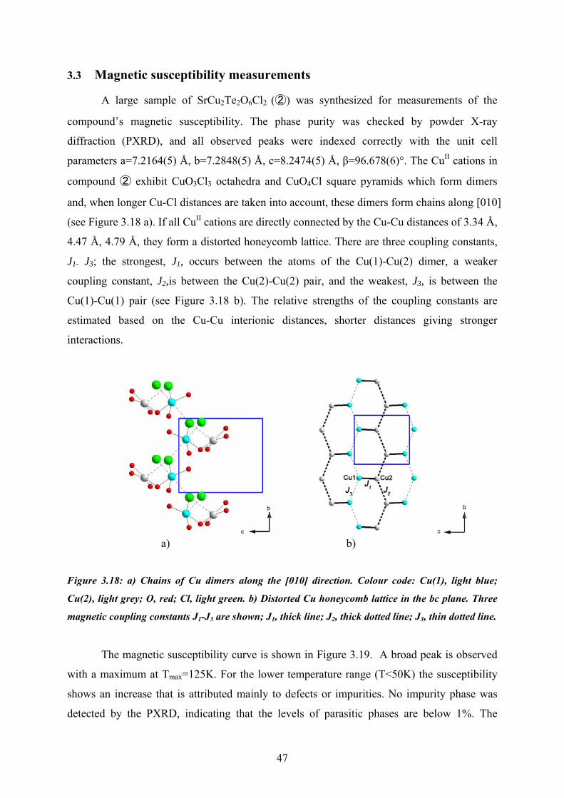
parameters a=7.2164(5) Å, b=7.2848(5) Å, c=8.2474(5) Å, β=96.678(6)°. The CuII cations in
compound ② exhibit CuO3Cl3 octahedra and CuO4Cl square pyramids which form dimers
and, when longer Cu-Cl distances are taken into account, these dimers form chains along [010]
(see Figure 3.18 a). If all CuII cations are directly connected by the Cu-Cu distances of 3.34 Å,
4.47 Å, 4.79 Å, they form a distorted honeycomb lattice. There are three coupling constants,
J1- J3; the strongest, J1, occurs between the atoms of the Cu(1)-Cu(2) dimer, a weaker
coupling constant, J2,is between the Cu(2)-Cu(2) pair, and the weakest, J3, is between the
Cu(1)-Cu(1) pair (see Figure 3.18 b). The relative strengths of the coupling constants are
estimated based on the Cu-Cu interionic distances, shorter distances giving stronger
interactions.
a) b)
Figure 3.18: a) Chains of Cu dimers along the [010] direction. Colour code: Cu(1), light blue;
Cu(2), light grey; O, red; Cl, light green. b) Distorted Cu honeycomb lattice in the bc plane. Three
magnetic coupling constants J1-J3 are shown; J1, thick line; J2, thick dotted line; J3, thin dotted line.
The magnetic susceptibility curve is shown in Figure 3.19. A broad peak is observed
with a maximum at Tmax=125K. For the lower temperature range (T<50K) the susceptibility
shows an increase that is attributed mainly to defects or impurities. No impurity phase was
detected by the PXRD, indicating that the levels of parasitic phases are below 1%. The

48
coupling constant parameters J and J’ were determined by comparison with Monte Carlo
simulation data; J = 193K and J’= 77K. J corresponds to the Cu(1)-Cu(2) dimer coupling J1
and J’ is a combination of J2 and J3. The Bleaney equation showed a close fit but no analytic
expressions of susceptibility χ(T) for dimers or chains exist.
Figure 3.19: Magnetic susceptibility χ measurements of SrCu2Te2O6Cl2 (②).

49
4 Summary
A number of compounds in the system AE-TeIV-TM-O-X (AE=Mg, Ca, Sr, Ba,
TM=CoII, NiII, CuII, X=Cl, Br) were synthesized, and their structures were determined by
single crystal X-ray diffraction methods. Most of the synthesized compounds are layered,
fulfilling one of the aims of this study: to obtain structures with new, low-dimensional
arrangements.
The idea of using lone pair elements as separators to reduce the dimensionality of
some features of the structure worked very well. A common structural theme emerged for the
layered compounds: The stereochemically active TeIV lone pairs divide the structures into
slabs (layered arrangement), protruding into a non-bonding regions between layers.
Furthermore, as lone pairs are non-bonding, they tend to agglomerate, much like the lipid tails
of surfactants, forming a bilayer. The non-bonding space separates the two sides of the layers
so that the remainder of the structure is cut down to low-dimensionality. A confluence of lone
pairs and halide ions was also observed, in congruence with the solubility of lipophilic species
within a surfactant bilayer. For compounds forming other, non-layered, structural
arrangements, different lone pair patterns were observed in the Te units. In one of the
examples (from compound ①) lone pair vectors from two neighbouring Te atoms make an
angle of almost 180° (up and down). In another example (from compound ②) the
corresponding angle is about 115°. In these cases, the lone pairs do not form continuous
surfaces, and rather than acting collectively to cut down the dimensionality of the whole
structure, their confluence with the halide ions creates small, non-bonding spaces in the
structure, quite reminiscent of rod-like micelles (the non-bonding tunnels ①) or spherical
micelles (the voids in ②).
Tellurium may take TeO3E or TeO3+1E coordination, and it is interesting to note that
for the case TeO3+1E the oxygen forming the forth, long bond is always connected to another
TeO3E or TeO3+1E unit in our new compounds. This may be understood in terms of bond

50
valence calculations showing that an oxygen atom connected to Te by the longer Te-O bond
at a distance of around ~2.4 Å is relatively highly negatively charged and thus always has to
connect to a neighbouring cation to be stabilized.
Utilization of the alkaline earth elements (AE) was another strategy to lower the
structure dimensionality. Clear examples of the success of this approach are given by the ①,
② and ③ cases where the AE units divide the remainder of the structures into sheets. In our
examples of layered compounds, ④ - ⑨, the AE units may be found in the slabs together with
the tellurium oxide substructures separating the rest of the components into sheets. A careful
look at all of these structures in detail reveals that the AE units sometimes contribute to
lowering the dimensionality of partial structures even more (cases ① - ③). Taking all these
observations together, we see that the AE units work as separators in all the structures. As the
non-magnetic units of the AE units effectively insulate the Te-TM-O-X sheets from each
other, they contribute significantly to the low dimensional magnetic behaviour of those
structures. It was remarkable that this idea of utilizing the AE cations as separator worked
uniformly across the structures synthesized and led to one new phase attainable in bulk
quantities sufficient for magnetic susceptibility measurements. (②).
Magnetic susceptibility measurements were performed on compound ② and the
corresponding susceptibility χ(T) curve was shown in Figure 3.19. In the crystal structure, the
Cu units form dimers, and if the longer Cu-Cl distances are taken into account, distorted Cu
honeycomb nets can be identified. Some of the coupling constants can be extracted from the
measurements, despite the fact that no simple analytic expressions for χ(T) of coupled dimers
exists.
It is also interesting to note that some of the new compounds introduced in this thesis
are found to be examples of violations to BVS theory (comp. ①, ④, ⑤, ⑥, ⑦, ⑧, and ⑨).
The BVS calculations were performed for all the compounds and the calculated values were
close to the expected values for the AE, Te, TM and O elements. For the halides, however, the
value was variable, from 0.1 to 1.1 vu. The reason for this unexpected range of values seems
to be related to the halides’ positions in the structure. For halides in the interlayer non-
bonding regions together with the lone pairs, the BVS value is low (0.1~0.4 vu), while when
halides are fully integrated into the covalent or ionic network, the BVS is close to be expected

51
value (~1.0 vu). In these higher BVS value cases, halides do not simply act as counter ions in
the structure, but should be considered as a part of the network of strong bonds.
It should be mentioned that while the synthetic work was relatively easy and gave rise
to a large number of new compounds, it is still difficult to achieve single phase samples in
these systems. The reaction methods are still under consideration and everything is still far
from clear. The prediction of structures is also very difficult indeed and no rules for when
particular building units should form have been determined. However, our strategies of
utilizing (1) TeIV as a lone pair element and (2) AE cations as chemical separators to lower the
dimensionality of the transition metal substructure worked beyond expectations, allowing us
to obtain nine new low dimensional compounds. It is fair to say that the hypothesis that lone
pair elements together with alkaline earth metals will yield low dimensional transition metal
arrangements has been confirmed here.

52
Acknowledgements
I would like to thank following persons who have supported me throughout my work. First of all, I would like to thank my supervisor Mats Johnsson for accepting me as a
Ph.D student and giving me this project. I learned a lot from your synthetic work and thank you for teaching me that. It was very useful to learn new synthetic work and visit international labs in Germany and Switzerland.
I would also like to express special thanks to my co-supervisor Sven Lidin for
accepting me here and introducing me to the crystallographic world. Your enthusiasm and passion for this work is amazing; I am so impressed. The atmosphere around you is warm and cozy, and it always gives a possible direction for work. I have been really lucky to meet you here in Stockholm, and work together with you. I enjoyed so much learning from you.
I am especially grateful to Lars Eriksson who is my special teacher in this department.
I really like your relaxing and happy atmosphere. I also enjoyed your lovely crystallography lectures from which I earned most of my knowledge. The teaching assistant experience was very interesting, too!
My regards also goes to our collaborator Peter Lemmens and Hans Henning Klaus.
Peter, thank you for introducing me to and teaching me Raman spectroscopy methods at Branschweig, Germany. The visit was very much fun, and it was a precious experience to broaden my knowledge of the magnetic field. Hans Henning, it was nice to work with you at PSI, Switzerland. I enjoyed a lot learning new methods of muSR; they were really facinating techniques.
I would like to thank my officemates who share the room with me and created a nice
atmosphere: Mirva Eriksson, Zuzana Hugonin, Bertrand Faure, and Ali Sharafat. For Kjell Jansson, thank you for your lectures on SEM & EDS. Lars Göthe, for your
careful caution of X-ray safety and help with the PXRD films. Rolf Eriksson & Per-Erik Persson, for your help with the computer administration. Per Jansson & Hans-Erik Ekström, for producing excellent goniometer pins and running a wonderful workshop in this department.
My thanks go as well as to all the people who help create a nice environment in the
inorganic & structure chemistry departments, especially: Ann-Britt Rönnell, Shuying Piao, Yanbing Cai, Juanfang Ruan, Miia Klingstedt, Thomas Björling, and Kadir Abdulkarim.
For Gunnar Svensson, thank you for giving me the experience to work with my
diploma student, Daisy. I learned a lot from this chance. Daisy Torino Hjelmquvist, it was

53
very much fun to work and talk with you even after you finished your work, and I was also glad to introduce you to one of my old friends, Cesar Pay Gόmez, who helped me when I first came here to start my Ph.D.
I can not forget those of you who supported me and share the nice feeling of talking in
my native language. Some of you are already back to Japan, but I will never forget the memories: Keiichi Miyasaka, Toyoto Sato, Tomohiro Utsumi, Yasuhiro Sakamoto, Tadahiro Yokosawa. I am also grateful to Osamu Terasaki for your kindness and the nice conversations we have had.
The life outside of the university was also quite important for me, especially my time at the Stockholm Ballet studio with my wonderful teacher Marie-Louise Montague. Karin Söderberg, thank you for introducing me to your world, and my favourite memories are of the times we went to classical concerts. Thanks also to Dag Noréus and Jacob Söderberg, who are fantastic pilots, for introducing me to the Stockholm sky world. It was definitely one of my unforgettable memories in Sweden.
Some of my family friends in Stockholm, Tomoyo & Niklas Johansson and Mizuho &
Ralph Ingre, your warmth and kindness are an important factor to my being here. Also Ayuka & Hideyuki Ishii with your lovely children, thank you for lots of enjoyable memories and experiences we had together in Stockholm.
My first chemistry teacher, Kazuhisa Kameda, it was a dramatic moment when I met
you for the first time in Japan. It was more than ten years ago but I still remember how I was amazed and impressed by your passion for chemistry. You are definitely one of the greatest teachers I have ever met and bestow the spirit of science upon so many people. My studying time in Stockholm was supported so much by you.
Lastly, my deepest regards go to my family, Shiro, Mie and Yumi Takagi for
supporting me during my studying periods. It was interesting to go on to the scientific field where my father worked before. My mother and sister’s constant support gave me so much positive energy and their lovely presents coming every month were so much fun! ...and to the last person, my husband Danny, I don’t find the simple words to express my best thankfulness to you, but with your infinite love and support everything becomes possible and happy!
Rie

54
References Andersson, S. & Åström, A. (1972). Nat. Bur. Stand. (U.S.) Spec. Publ. 364, 3-39. Andersson, S., Åström, A., Galy, J. & Meunier, G. (1973). J. of Solid State Chem. 6, 187-190. Arnaud, Y., Averbuch-Pouchot, M. T., Durif, A. & Guidot, J. (1976). Acta Cryst., B32, 1417-1420. Åström, A & Andersson, S. (1971). Acta Chem. Scand. 25, 1519-1520. Becker, R., Johnsson, M., Kremer, R. K. & Lemmens, P. (2005). J. Solid State Chem. 178, 2024-2029. Becker, R. & Johnsson, M. (2004). Solid State Sci. 6(6), 519-522. Becker R., Johnsson M., Kremer R.K. & Lemmens P. (2003). Solid State Sci. 5, 1411-1416.
Bednorz, J.G. & Müller, K.H. (1986). Zeit. Phys. B64, 189 Brandenburg, K. (2001). DIAMOND Release 2.1e. Crystal Impact GbR, Bonn, Germany. Brese, N.E. & O'Keeffe, M. (1991). Acta Cryst. B47, 192. Brown, I.D. (2002). ‘The Chemical Bond in Inorganic Chemistry, The bond valence model’, International Union of Crystallography, Oxford Science Publications. Brown I.D., Bond valence sum parameters. http://www.ccp14.ac.uk/ccp/web-mirrors/i_d_brown/bond_valence_param/ Brown, I.D. & Altermatt, D. (1985). Acta Cryst. B41, 244-247. Dorset, D.L.;McCourt, M.P. (1994). Acta Cryst. A50, 344-351. Eriksson, L. (2004). REFLEX, a computer program for the handling of single crystal diffraction data. Stockholm University, Sweden. Farrugia, L. J. (1999). WinGX, J. Appl. Cryst. 32, 837-838. Feger, C.R. & Kolis, J. W. (1998). Inorg. Chem. 37, 4046-4051. Galy, J. (1972). Nat. Bur. Stand. (U.S.) Spec. Publ. 364, 29-39. Galy, J., Meunier, G., Andersson, S. & Åström, A. (1975). J. Solid State Chem. 13, 142-159. Galy, J. & Enjalbert, R. (1982). J. Solid State Chem. 44, 1-23. Galy, J., Enjalbert, R., Rozier, P. & Millet, P. (2003). Solid State Sciences. 5, 165-174.

55
Gillespie, R.J. & Nyholm, R.S. (1957). Quart. Rev. 11, 339. Greewood, N. N. & Earnshaw, A. (1997). Chemistry of the Elements, 2nd edn., Elsevier Ltd., 107-138. Grenville-Wells, H.J.;Lonsdale, K. (1958). Nature (London) 181, 758-759. Gros, C., Lemmens, P., Vojta, M., Valenti, R., Choi, K.-Y., Kageyama, H., Hiroi, Z., Mushnikov, N. V., Goto, T., Johnsson, M. & Millet, P. (2003). Phys. Rev. B: Condens. Matter Mater. Phys. 67(17), 174405/1-174405/5. Hassel, O. (1924). Zeitschrift fuer Physik. 25, 317-337. Hottentot, D. & Loopstra, B.O. (1983). Acta Cryst. C39, 1600-1602. Hull, A.W. & Davey, W.P. (1921). Phys. Rev. 17, 266-267. Johansson, K.E., Palm, T. & Werner, P.E. (1980). J. Phys. Sci. Instrum. 13, 1289-1291. Johnsson, M., Törnroos, K. W., Mila, F., & Millet, P. (2000). Chem. Mater. 12, 2853-2857. Johnsson, M., Törnroos, K. W., Lemmens, P. & Millet, P. (2003). Chem. Mater. 15, 68-73. Johnsson, M., Lidin, S., Törnroos, K. W., Bürgi, H.-B. & Millet, P. (2004). Angew. Chem. Int. Ed. 43, 4292-4295. Johnston, M. G. & Harrison, W. T. A. (2002). Acta Cryst. E58, i49-i51. Kipka, R.;Mueller-Buschbaum, H. (1976a). Z.eitschrift fuer Naturforschung, Teil B. Anorganische Chemie, Organische Chemie. 31, 1067-1069. Kipka, R.;Mueller-Buschbaum, H. (1976b). Z. Anorg. Allg. Chem. 419, 58-62. Kipka, R.;Mueller-Buschbaum, H. (1976c). Z. Anorg. Allg. Chem. 424, 1-4. Kipka, R.;Mueller-Buschbaum, H. (1977). Zeitschrift fuer Naturforschung, Teil B. Anorganische Chemie, Organische Chemie, 32, 124-126. Kreitlow, J., Suellow, S., Menzel, D., Schoenes, J., Lemmens, P. & Johnsson, M. (2005). J. Magn. Magn. Mater. 290-291(Pt. 2), 959-961. Lemmens, P., Choi, K.-Y., Guentherodt, G., Johnsson, M., Millet, P., Mila, F., Valenti, R., Gros, C. & Brenig, W. (2003). Phys. B (Amsterdam, Neth.) 329-333(Pt. 2), 1049-1050. Lemmens, P., Choi, K. Y., Ionescu, A., Pommer, J., Guntherodt, G., Valenti, R., Gros, C., Brenig, W., Johnsson, M., Millet, P., Mila, F. (2002). J. Phys. Chem. Solids. 63, 1115-1117. Lemmens, P., Choi, K.-Y., Kaul, E.E., Geibel, C., Becker, K., Brenig, W., Valenti, R., Gros, C., Johnsson, M., Millet, P. & Mila, F. (2001). Phys. Rev. Lett. 87, 22, 227201/1-227201/4.

56
Lemmens, P. and Millet, P. (2004). “Spin – Orbit – Topology, a Triptych.” Lect. Notes Phys. 645, 433-477. Lewis, G. N. (1916). J. Am. Chem. Soc. 38, 762-786. Menchetti, S.& Sabelli, C. (1976). Neues Jahrbuch fuer Mineralogie. 1976, 406-417. Petřίček, V., Dušek, M. & Palatinus, L. (2000). JANA2000. Institute of Physics AVCR, Cukrovarnicka 10, 162 53 Praha, Czech Republic Shannon, R.D. (1976). Acta Cryst. A32, 751-767. Shannon, R.D. & C.T. Prewitt (1969). Acta Cryst. B25, 925-946. Sheldrick, G.M. (1997). SHELXS97 and SHELXL97. University of Göttingen, Germany. STOE & Cie GmbH. (1999). X-RED Version 1.22. Stoe & Cie GmbH, Darmstadt, Germany. STOE & Cie GmbH. (2001). X-SHAPE Revision 1.06. Stoe & Cie GmbH, Darmstadt, Germany. Wells, A. F. (1984). Stractural Inorganic Chemistry, 5th edn., Oxford University Press, Oxford, 1382pp. Werner, P.E. (1969). Arkiv för kemi, 31, 513-516. Ziebarth, R. P. & Corbett, J.D. (1988). J. Am. Chem. Soc. 110, 1132-1139. Zhang, J. & Corbatt, J. D. (1991). Z. anorg. Allg. Chem. 598/599, 363-370. Zaharko, O., Roennow, H., Mesot, J., Crowe, S. J., Paul, D. McK., Brown, P. J., Daoud-Aladine, A., Meents, A., Wagner, A., Prester, M. & Berger, H. (2006). Phys. Rev. B: Condens. Matter Mater. Phys. 73(6), 064422/1-064422/7.

57

58
Hinc lucem et pocula sacra
“From here, we gain enlightenment and precious knowledge”