a new movement authority based on vehicle-centric
TRANSCRIPT

Research ArticleA New Movement Authority Based on Vehicle-CentricCommunication
Tuo Shen 1 and Haifeng Song 2
1School of Optical-Electrical and Computer Engineering, University of Shanghai for Science and Technology, Shanghai 200093, China2Institute for Traffic Safety and Automation Engineering, Technische Universitat Braunschweig, 38108 Braunschweig, Germany
Correspondence should be addressed to Haifeng Song; [email protected]
Received 7 December 2017; Revised 16 February 2018; Accepted 4 March 2018; Published 4 April 2018
Academic Editor: Li Zhu
Copyright © 2018 Tuo Shen and Haifeng Song. This is an open access article distributed under the Creative Commons AttributionLicense, which permits unrestricted use, distribution, and reproduction in any medium, provided the original work is properlycited.
The communication system that is presently applied in the European Train Control System can only support data exchange betweenvehicles and ground, but the direct vehicle-to-vehicle communication is not available. The details of interlocking information andother vehicles’ movements are invisible to drivers who are the last defense to prevent unsafe scenarios. As connected vehicles havebeen envisioned to enhance transportation efficiency and improve safety, the direct vehicle-to-vehicle communication network isinvolved in this paper to increase the safety of railway transport. In this paper, a new train movement authority (MA+) is proposed.Apart from a wireless communication unit, this system does not require any other infrastructure. With the assistance of vehicle-centric communication technology, MA+ can detect the condition of switches and trains within a certain scope. In this paper, thesystem structure of MA+ is proposed. Additionally, different implementation scenarios are also discussed. The detection range isestimated and validated based onmathematical calculation and experimental equations. An application demo ofMA+ is presentedon the Driver Machine Interface of the onboard equipment. The results indicate that MA+ can be a flexible and scalable system forfurthering the improvement of railway safety.
1. Introduction
To guarantee railway transport safety, various technologieshave been applied.The latest European Train Control System(ETCS), which is based on the moving block principle, safelyoptimizes the maximum capacity of the rail network. Dif-ferent kinds of data are submitted to the Centralized TrafficControl (CTC) system, such as the interlocking information,train position, and train diagram. Hence, CTC has a “God’sview” of all trains and interlocking details [1]. The RadioBlock Center (RBC) transfers the movement authority (MA)to the trains in its scope of jurisdiction.The train vehicles canonly passivelymove based on theMA.Once theMA is a fault,it may lead to a risk scenario, which results in catastrophicconsequences.
For instance, in the 2016 Berlin Tram-Crash, two com-muter trains collided on a single-track stretch of railway inGermany; additionally, there was a head-on collision involv-ing two passenger trains in southern Italy; two cargo trains
collided in Finland; the 7.23 Yongwen line train collision andthe Shanghai Metro Line 10 collision in China are furtherexamples [2]. As shown in Figure 1, even though the latesttechnologies have been implemented, accidents happened allthe same. Hence, we should not be lulled by the guarantee ofthe train control system safety.
Based on the technology trends, the train control sys-tem should weaken the proportion of ground faculties andprovide trains with more information than in the past [3].Some projects based on the vehicle-centric communicationshave been carried out in these years [4]. For instance,Alstom offered a train-centric communications-based traincontrol (CBTC) system. This system can carry out directtrain-to-train communication and control the switch by thetrain. With implementing this system, the maintenance costshave been decreased by 20% and energy has been savedup to 30% [5]. Publication [6] introduces a train collisionavoidance system, which is based on the Global NavigationSatellite System (GNSS) to obtain the location data; potential
HindawiWireless Communications and Mobile ComputingVolume 2018, Article ID 7451361, 10 pageshttps://doi.org/10.1155/2018/7451361

2 Wireless Communications and Mobile Computing
2006 2007 2008 2009 2010 2011 2012 20130
50100150200250300350400
Time
Num
bers
of e
vent
s and
vic
tims
VictimsAccidents
Figure 1: Numbers of events and victims of train collisions andderailments in Europe from 2006 to 2013.
collisions are avoided in the future. Publication [7] proposeda direct vehicle-to-vehicle distance measurement system inrailways, and the system availability is validated by usingcolored Petri nets.
Varying from the systems mentioned in publications [5–7], in this paper, we propose a system that requires no addi-tional position and speed measurement system.The essentialinformation is collected using the internal wireless packetsgenerated by ETCS’s onboard equipment. The vehicle-to-vehicle data exchange is implemented via a vehicle-centriccommunication link.
Improving transport safety requires numerous suitablemethods. Reducing transitions to hazardous operations andincreasing transitions to safer operations are the most effec-tive implementation methods [8]. Limiting movement viola-tion is one of the most efficient and innovative methods toreduce accidents, such as train-to-train and train-object col-lisions. This paper intends to provide researchers with a newmovement authority (MA+), which combines advantages ofthe vehicle-centric communication with current movementauthority (MA) mechanisms.
MA+ works as a supplementary part of the ETCS. Whenthe ETCS is working normally and there is no potential risk,MA+ will remain silent. Otherwise, MA+ outputs a warningor alarm. It is important to know that MA+ cannot replacethe statue of the current MA. This is mostly due to the factthat the safety of MA+ cannot achieve an equivalent securitylevel as compared with the ETCS in its infancy. Furthermore,any modifications of this current system require a substantialamount of discussion and verification. This paper focuses onsuch a proposal and the system description.
The remainder of the paper is organized as follows:Section 2 is dedicated to discussing the system’s structure anddifferent application scenarios. The feasibility of proposinga new movement authority, which is based on the vehicle-centric communication, is also further discussed in Section 3.In Section 4, an MA+ interface demo is introduced on theDriver Machine Interface (DMI), which can be utilized forthe further simulation or practical application in the actualsystem. Finally, Section 5 presents the conclusion and furtherworks.
2. Structure and Application Scenarios of MA+
As defined in ETCS-2, the MA contains the distance infor-mation, by which the train is authorized to move forward[9]. However, no surrounding details are available for thetrain. The MA+ proposed in this paper can obtain extrainformation by applying the vehicle-centric communicationmethod. The extra information includes but is not limitedto other trains’ speed and position and switch’s positionand situation. In this section, the system structure, logicalmodel, and data exchange process are presented; differentimplementation scenarios are then further discussed.
2.1. MA+ Structure and LogicalModel Description. Except forthe existing infrastructures in ETCS-2, there are two maincomponents in the structure of MA+. As shown in Figure 2,the vehicle-centric communication architecture is installed ineach train, and this architecture permits internal and exter-nal data exchange. The switch announcement architecturerepeatedly broadcasts the switch’s location and situation.
The communication link between vehicles and switchesis shown in Figure 3. In the vehicle-centric communicationarchitecture, the MA+ algorithm collects the train messagesfrom the onboard equipment and transmits the informationvia the Transceiver Unit. These messages provide the train’sMA, speed, position, direction, and vehicle ID number. TheTransceiver Unit is also in charge of receiving the trainmessages sent by other vehicles and switch messages fromthe switch announcement. After obtaining the MA andlocalization data, theMA+ algorithmmatches the digital mapand displays which particular track the train is on throughthe DMI. When there are potential hazardous scenarios, theMA+ algorithm will output alarms.
Before the communication link between vehicles andswitches is established, MA+ works in a surveillance mode(Smod). As shown in Figure 4, there are no switches andtrains in its detection range; the blue line and the yellowline represent the original MA data and the MA route,respectively. The system continuously detects the situation ofpotential nearby switches and trains.
The overall logical model of the MA+ algorithm is shownin Figure 5. MA+ starts from IDLE and turns into Smod afterobtaining the train message data. Combining with the digitalmap, the MA+ shows which track the train is on (MA+ T).Once the information is sufficient to be updated, the MA+turns into corresponding modes (T, V, and S representtrack, vehicle, and switch, resp.). For instance, MA+ T Sdisplays the track and switch details once the MA+ obtainsthe information broadcasted by the switch announcementarchitecture. Some specific situations trigger shortening MA(SMA), and the MA will be updated based on a new end ofauthority (EOA). In the following section, the logical detailsare discussed based on different scenarios, which are used todescribe how MA+ is implemented.
2.2. MA+ Implementation Scenarios. A switch can lead atrain onto a different path. Hence, obtaining the position andsituation of the approaching switch is essential in the MA+implementation. Vehicle-to-switch communication provides

Wireless Communications and Mobile Computing 3
CTC
Interlocking
Radio Block CenterGMS-R
DMI
Empty line
Operation lineDistance scale
Switch
GMS-R
Vehicle-centric communicationarchitecture
Brings basic information ofapproaching switch and
encountered train
Switch announcementRepeatedly announce
the switch position andsituation
Vehicle-to-switchcommunication
Vehicle-to-vehiclecommunication
−
+
+
+
0
0
0
5
221000
2000
4000
8000
−
−
Figure 2: Structure of MA+.
Transceiver Unit
Switch messages/trainmessages
MA+ algorithmPosition
Direction
Digital map
Trainmessages
DMI
Vehicle-centriccommunicationarchitecture #1
MA
Speed
ID#1 Alarm
Vehicle-centriccommunicationarchitecture #2
Transceiver Unit
Switch algorithm ID #1Switch situationchecking sensor
Switchmessages
Switch announcement #1
Figure 3: Communication link between vehicles and switches.
fundamental vector information. The following proceduresare involved: surveillance, detection and appropriate avoid-ance, and output results:
(i) Surveillance: the local MA+ works in a monitor-ing mode. The switch announcement continuouslybroadcasts its location and position
(ii) Detection and appropriate avoidance: once the con-nection between the switch announcement and thelocal vehicle-centric communication architecture isestablished, the local system turns to the appropriateavoidance mode
(iii) Output results: after obtaining the position and situ-ation of the approaching switch, the system’s outputresults vary depending on different scenarios
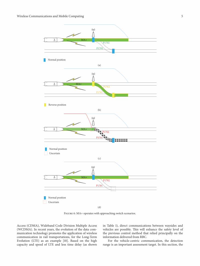
In the appropriate avoidance procedure, the switch condi-tions are described as shown in Figure 6. In this section, fourdifferent combinations of the switch conditions are discussedto do the illustration. The red line represents the SMA. The
blue and yellow rectangles indicate the normal and reverseswitch positions, respectively. The switch’s name turns intogreen or yellow depending on the switch position.
In the normal operation the switch position can be shownas Figures 6(a) and 6(b), which represent the situation that theswitch is in normal and reverse positions, respectively. Whenthe switch is in an uncertain position, it will be marked withred-dotted lines as shown in Figures 6(c) and 6(d).
It is important to note that situations 3 and 4 do notexist when the interlocking system is working correctly. TheETCS is a critical safety system, and theMA generation obeysspecific fault-safety strategies. Under the scenario illustratedin Figure 6(c), switch split is likely to occur along with derail-ments and side collisions. Hence, among these four differentscenarios, only this one can trigger the SMA. Additionally, toreduce the frequency of false alarms, the following conditionis considered. When the original MA is available and thedatabase shows that there is an approaching switch but thevehicle-to-switch connection is not established, the systemignores this scenario and no SMA is required.

4 Wireless Communications and Mobile Computing
A
Original MA (train A)
Figure 4: MA+ surveillance mode.
IDLE
Smod
Obtain data
Refresh
MA+_T
Digital map matching
MA+_T_S
Detect switch
Shorten MA
Hold MA
MA+_T_V
Hold MAShorten MA
Detect othervehicles
MA+_T_V_S
Shorten MA
Hold MADetect switch
Detect othervehicles
Refresh
Internal dataExternal data
Figure 5: Logical model of the MA+ algorithm.
Different like the vehicle-to-switch communication,moreinformation has to be taken into consideration when thevehicle-to-vehicle communication is established. If train Adetects another train B in its detection range, train Acommunicates with train B and obtains the MA+ details oftrain B. In general, the scenarios can be divided into twomainparts:
(i) There is no overlap of the two MA, as shown inFigure 7(a). The green part is the available extensionarea for the detected trains’ MA. Under this scenario,train A’s EOA can be reached without a risk for ahazardous situation (the train position is calculatedbased on the train’s head position; the absolute reallength of the train should be considered when SMAis triggered).
(ii) If the routes of train A and train B have an overlapas shown in Figure 7(b), both of them have to activatethe SMA based on their speed and position to preventcollisions as shown in Figure 7(c).
The practical situations are the combinations of afore-mentioned scenarios of switches and trains. When driversare required to take responsibility, they can have an extendedversion of the surrounding switches and trains in a certaindistance with the assistance of MA+. For drivers, the benefitof MA+ implementation is that it helps them understand
better the surrounding environment of tasks they have toperform, especially in special scenarios where the drivershave to make sure the situation of the train ahead is safe.For instance, the onboard equipment works in modes as ONSIGHT (OS), ISOLATION (IS), and so on. Hence, MA+ isan efficient way to extend drivers’ ability and improve theoperational safety.
The contemporary control system has a high safety level.However, if the signal system fails, the “driver see and avoid”will be activated. MA+ can output alarm and shorten theMAautomatically; furthermore, it should be kept in radio silenceif there is no potential accident. Otherwise, MA+ can alsobe turned on manually. Hence, it is clear that MA+ will notincrease drivers’ responsibility and workload. Additionally, itcan also provide additional communication other than justthe communication between trains and ground.
3. MA+ Detection Range Estimation
Any theoretical proposal should be put forward in engi-neering implementation, and then the proposal makessense. Before the practice using, a suitable simulation basedon an existing technology is essential. For the vehicle-centric communication, different kinds of communica-tion technologies are available, such as Global System forMobile Communications (GSM), Code Division Multiple
Wireless Communications and Mobile Computing 5
MA+
P1701
P1702
Normal position
A
(a)
MA+
P1701
P1702A
Reverse position
(b)
MA+
P1701
P1702A
Normal positionUncertain
(c)
MA+
P1701
P1702
Normal position
Uncertain
A
(d)
Figure 6: MA+ operates with approaching switch scenarios.
Access (CDMA), Wideband Code Division Multiple Access(WCDMA). In recent years, the evolution of the data com-munication technology promotes the application of wirelesscommunication in rail transportations, for the Long-TermEvolution (LTE) as an example [10]. Based on the highcapacity and speed of LTE and less time delay (as shown
in Table 1), direct communications between waysides andvehicles are possible. This will enhance the safety level ofthe previous control method that relied principally on theinformation delivered from RBC.
For the vehicle-centric communication, the detectionrange is an important assessment target. In this section, the

6 Wireless Communications and Mobile Computing
A
Original MA (train A)
BK321+000 K337+000
K337+000BB
Safe distance
No overlap of movement authority
(a)
A
Original MA (train A)
BK321+000K318+000
Original MA (train B)
(b)
MA+MA+A
SMA (train B)
B
SMA (train A)
Safe distance
With overlap of movement authority
(c)
Figure 7: MA+ operates with encountering trains.
Table 1: The maximum time delays comparison of mobile commu-nication system.
Communication system Maximum time delay (10−6 s)GSM 1.805CDMA2000 0.813WCDMA 0.130LTE 0.030
distance detection range of MA+ is discussed based on thepath loss calculation.
Different factors have various influences on the signalquality. One harsh transition environment is that in non-line-of-sight (NLOS) propagation with mountain barrier, forexample, in railway curve lines, as shown in Figure 8. Underthis scenario, the path loss in curve line is treated as a singleround obstacle for mathematical calculations. Here,ℎ is height of the curve line above the straight line of
the local train and detected train,𝑅 is the radius of the curve line,𝑑1, 𝑑2 are the tangent lines through the local train anddetected train position.
The diffraction loss is influenced by the frequency, curveradius, and distance. The mathematical calculation is based
h
R
R
Local train
Detected object
d1
d2
Figure 8: The power attenuation simulation in the curve lineapplication scenario.
on the International Telecommunication Union (ITU) rec-ommendation [11]. The attenuation loss 𝐴 can be calculatedas follows:
𝐴 = 𝐽 (V) + 𝑇 (𝑚, 𝑛) , (1)
where 𝐽(V) is the Fresnel-Kirchhoff loss caused by equivalentblade shape barrier and it can be given by

Wireless Communications and Mobile Computing 7
X: 3350Y: 6100Z: 158.2
160
140
120
100
80
60
40
20
0
Atte
nuat
ion
(dB)
6000 5000 4000 3000 2000 1000
Distance (m)
140
120
100
80
60
40
20
Radius (m)40008000
12000
Figure 9: Wireless power attenuation with distance and radius.
𝐽 (V)= −20 log(√[1 − 𝐶 (V) − 𝑆 (V)]2 + [𝐶 (V) − 𝑆 (V)]22 ) , (2)
where 𝐶(V) and 𝑆(V) are the real and imaginary partsof Fresnel integral, respectively. For the transition with abarrier blocking the line-of-sight transmission, 𝐽(V) can beapproximately described as follows:
𝐽 (V) = 6.9 + 20 log(√(V − 0.1)2 + 1 + V − 0.1) , (3)
V = 0.0316ℎ [2 (𝑑1 + 𝑑2)𝜆𝑑1𝑑2 ]1/2 , (4)
where ℎ and 𝜆 are in meters, 𝜆 is the wavelength, and 𝑑1, 𝑑2are in kilometers.𝑇(𝑚, 𝑛) is the additional loss caused by barrier curvature,which is the curve line radius 𝑅.𝑚 and 𝑛 are given by (5) and(6), respectively:
𝑚 = 𝑅 [(𝑑1 + 𝑑2) /𝑑1𝑑2][𝜋𝑅/𝜆]1/3 , (5)
𝑛 = ℎ [𝜋𝑅/𝜆]2/3𝑅 . (6)
When𝑚𝑛 ≤ 4, 𝑇(𝑚, 𝑛) equals (7); when𝑚𝑛 > 4, 𝑇(𝑚, 𝑛)equals (8).
𝑇 (𝑚, 𝑛) = 7.2𝑚1/2 − (2 − 12.5𝑛)𝑚 + 3.6𝑚3/2 − 0.8𝑚2, (7)𝑇 (𝑚, 𝑛) = −6 − 20 log (𝑚𝑛) + 7.2𝑚1/2 − (2 − 17𝑛)𝑚
+ 3.6𝑚3/2 − 0.8𝑚2. (8)
In Europe, LTE frequencies are bands 1/3/7/8/20. Band 8is currently used mostly by GSM. Band 8 is attractive froma coverage point of view due to the lower propagation losses.Theband can be reused for LTE orHSPA. Bands 8 and 20 holdthe uplink frequencies 880–915MHz and 832–862MHz. Thedownlink frequencies are 925–960MHz and 791–821MHz[12]. Here we choose the frequency 930MHz to do thesimulation. The result is shown in Figure 9, which indicates
0 1000 2000 3000 4000 5000 6000 7000−100−90−80−70−60−50−40−30−20−10
Distance between transmit antenna and receive antenna (m)
Rece
ive p
ower
(dBm
)
SuburbanOpen area
Mountain areaUrban
Figure 10: Receive signal power in different scenarios.
the interrelationship among the diffraction loss, detectiondistance, frequency, and radius. The received signal powershould be greater than the sensitivity of a receiver, as shownin (9). 𝑃𝑟 (𝑑) [dBm] = 𝑃𝑡 [dBm] + 𝐺 − 𝐴 − 𝑃𝐿Δ, (9)
𝐺 = 10 log (𝐺𝑡𝐺𝑟) , (10)
where 𝑃𝑟(𝑑) [dBm] is the received power; 𝑃𝑡 [dBm] is thetransfer power; 𝐺 is the gain; 𝐺𝑡 and 𝐺𝑟 are the gains ofthe transfer and receiver antennas, respectively; 𝑃𝐿Δ is theattenuation caused by device and feeder cable.
For the received power, some experimental data is avail-able to be referenced. In publication [13], the path lossmeasurements at the 930MHz in the different scenario weredone. The empirical power of received signal models forsuburban area, open area, mountain area, and urban area wasproposed, as shown in (11), (12), (13), and (14), respectively.The simulation result is shown in Figure 10. As shown inthe result, the received signal power is greater than −90 dBmwithin 4000m. Hence, the detection range is not a limitationof this system’s practical application. Taking ICE-3 as anexample, the train emergency braking distance is between2300 and 2800m depending on the actual speed.𝑃𝑟 (𝑑) = 21.577 − 28.001 log (𝑑) , (11)
𝑃𝑟 (𝑑) = 6.0246 − 21.2261 log (𝑑) , (12)
𝑃𝑟 (𝑑) = 38.432 − 35.015 log (𝑑) , (13)
𝑃𝑟 (𝑑) = 61.337 − 40.452 log (𝑑) . (14)
Here we take an actual line as a case study.Theminimumrailway curve radius is different in various railway lines, andseveral cases are shown in Table 2 [14].The simulation resultsindicate that, under the minimum curve radius of 3350min Koln-Rhein/Mann line, the signal attenuation is 158.2 dBwhen the detected distance is 6100m. In current practiceapplication, the typical maximum path loss of LTE can be163.5 dB [15]. In order to make the detection range as further

8 Wireless Communications and Mobile Computing
Table 2: Symbol form/shape and descriptions.
Symbol No. Form/shape DescriptionSW1 Switch in normal positionSW2 Switch in reverse positionSW3 Switch in reverse and normal positionSW4 Switch in normal and reverse position
TR1 Train without collision riskTR2 Train with collision riskTC1 Operation lineTC2 Empty line
100
200
400
800
Train position
Indication marker
Speed profile discontinuity(speed decrease)
Planning area speed profile
Speed profile discontinuity(target at speed zero)
Hide/show planning information
Zoom function
Gradient profile
Orders and announcementsof track conditions
Distance scale
Zoom function −
+
+
+
0×
0
5
−
−
22
Figure 11: Main objects of the planning information.
as possible, many different methods can be used, for instance,choosing a suitable wireless frequency spectrum accordingto the simulation result in Figure 9, increasing transmitterpower, enhancing receiver sensitivity, and building repeaterstations. Both the simulation result and practical resultsindicate that the vehicle-centric communication is availableat the technical level. Hence, the detection range is not alimitation of the MA+ practical application.
4. An Application Demo on the DMI
The MA+ can be merged into the current train controlsystem. In this section, a demo is proposed on the DMIof ETCS. The onboard equipment displays the essentialinformation on the DMI for drivers. MA+ is combined withthe planning information on DMI. On DMI, the orders andannouncements overview displays within the MA and upto the first target at zero speed. The following aspects areinvolved, if any, as shown in Figure 11.
Here we add MA+ information in orders and announce-ments of track conditions area, and the basic symbols areshown inTable 3. Symbols or shapes having a certainmeaningin general railway control systems are avoided, and the displaypermits no interaction with the driver during the normaloperation.
Operation line and empty line are defined in the localtrain’s view. Based on the switch conditions, there are differentMA operation routes. The driver will know which route isbeing implemented. As shown in Figure 12, the length of MA
is assumed to be 800m. The train was transferred from thecurrent operation line to the empty line through SW2, whichlocates at 280m in front, as shown in Figure 12(b). SW3 andSW4 are in hazardous conditions; trailed switch accidentsmay happen. SW3 will lead the local train to another trackand switch split will occur. Hence, SMA is required andan alert is triggered. There is no risk of collisions to thelocal train under SW4, and no SMA action can be triggeredautomatically.
Once other trains are detected and if there is no overlapbetween operation lines, the system will show the positionsof other trains as green symbols. The angle shows thetrain operation direction. If there are overlaps between twooperation lines, SMA is immediately executed.Then, becauseof different train directions, two different scenarios should bediscussed: scenario one: after the new EOA was refreshed,there is still an overlap of the MA of two trains; both twotrains have to shorten their MA again based on their speed,distance, and location, as shown in Figure 13(a); scenario two:if the detected trains and local train have the same routedirection, the new EOA will be updated based on the end ofthe detected train, as shown in Figure 13(b).
5. Conclusion and Further Work
In this paper, a new movement authority based on vehicle-centric communication was proposed to increase the safetylevel of the railway operation. The structure of the systemwas given, and implementation scenarioswere also discussed.

Wireless Communications and Mobile Computing 9
Table 3: Comparison among different curve radiuses.
Organization JR JR DB DB SNC SNCF CRHItem Tokaido Shinkansen Tokyo-Joetsu Hannover-Wrzburg Koln-Rhein/Mann Paris-Sud-Est Atlantique Beijing-ShanghaiMaximumdesign speedkm/h null 280 300 300 350 380 380
Maximumservice speedkm/h 300 275 250 null 270 300 300
Minimum curveradius m 4000 4000 7000 3350 4000 6250 7000
100
200
400
800−
−
−
+
+
+
0
0
22
5
(a)
100
200
400
800−
−
−
+
+
+
0
0
22
5
(b)
100
200
400
800−
−
−
+
+
+
0
0
22
5
(c)
100
200
400
800−
−
−
+
+
+
0
0
22
5
(d)
Figure 12: DMI operates with approaching switch scenarios.
With the assistance of vehicle-centric wireless communica-tion, local trains can have an overview of surrounding scenar-ios. By estimating the detection range based on attenuationcalculation, the results indicated that this vehicle-centriccommunication proposal was engineering-feasible. Finally,a demo for the MA+ application on DMI was presented.It is clear that similar vehicle-centric technologies can bewidely used in the future to increase the safety level of railwaytransport.
In further works, an MA+ prototype machine will bedesigned, which can carry out the fundamental functionsproposed in this paper. Given that the current DMI has beendeveloped with a view to optimizing information provisionand providing drivers with the information they need, anychange to the DMI and information provided should be val-idated under careful consideration. Hence, in the followingresearch, we will try to get railway companies support torevise the system’s industry requirements and provide a more

10 Wireless Communications and Mobile Computing
100
200
400
800−
+
+
+
0
0
5
−
−
22
(a)
100
200
400
800−
+
+
+
0
0
5
−
−
22
(b)
Figure 13: DMI with detected trains.
actual analysis. A full function device will be available to beapplied on the actual DMI.
Conflicts of Interest
The authors declare that there are no conflicts of interestregarding the publication of this paper.
Acknowledgments
This work is supported by the National Natural ScienceFoundation of China (U1734211 and 61603026), ShanghaiCommittee of Science and Technology research program(17DZ1100106), and BeijingMunicipal Natural Science Foun-dation (I18E300010 and L171004).
References
[1] H. Song and E. Schnieder, “Modeling of railway systemmaintenance and availability by means of colored petri nets,”Maintenance and Reliability, vol. 20, no. 2, pp. 232–239, 2018.
[2] H. Dong, B. Ning, Y. Chen et al., “Emergency managementof urban rail transportation based on parallel systems,” IEEETransactions on Intelligent Transportation Systems, vol. 14, no.2, pp. 627–636, 2013.
[3] J. Wang, J. Wang, C. Roberts, and L. Chen, “Parallel monitoringfor the next generation of train control systems,” IEEE Trans-actions on Intelligent Transportation Systems, vol. 16, no. 1, pp.330–338, 2015.
[4] B. Ai, X. Cheng, T. Kurner et al., “Challenges toward wirelesscommunications for high-speed railway,” IEEE Transactions onIntelligent Transportation Systems, vol. 15, no. 5, pp. 2143–2158,2014.
[5] J. Moreno, J. Riera, L. De Haro, and C. Rodriguez, “A survey onfuture railway radio communications services: challenges andopportunities,” IEEE Communications Magazine, vol. 53, no. 10,pp. 62–68, 2015.
[6] A. Lehner, T. Strang, and C. R. Garca, “A reliable surveillancestrategy for an autonomous rail collision avoidance system,” inProceedings of the 15th ITSWorld Congress, New York, NY, USA,2008.
[7] H. Song and E. Schnieder, “Validation, verification and evalua-tion of a train to train distance measurement system by meansof colored petri nets,” Reliability Engineering and System Safety,vol. 164, pp. 10–23, 2017.
[8] E. Schnider, “Traffic safety and availability - contradiction orattraction,” in Proceedings of 2nd International Symposium ofNetworks for Mobility, 2004.
[9] “Ertms/etcs - baseline 3, system requirements specification.chapter 3, principles, subset-026-3, issue 3.0.0. 23, 2008”.
[10] L. Lei, J. Lu, Y. Jiang et al., “Stochastic delay analysis for traincontrol services in next-generation high-speed railway commu-nications system,” IEEE Transactions on Intelligent Transporta-tion Systems, vol. 17, no. 1, pp. 48–64, 2016.
[11] ITU-R Recommendation P.526-11, “Propagation by diffraction,2009”.
[12] H. Holma and A. Toskala, LTE for UMTS: Evolution to LTE-advanced, John Wiley and Sons, 2011.
[13] R. He, B. Ai, Z. Zhong, A. F. Molisch, R. Chen, and Y. Yang,“Ameasurement-based stochasticmodel for high-speed railwaychannels,” IEEE Transactions on Intelligent Transportation Sys-tems, vol. 16, no. 3, pp. 1120–1135, 2015.
[14] M. Lindahl, “Track geometry for high-speed railways,” TRITA-FKT Report, Tech. Rep., 54.
[15] H. Abid, T. C. Chung, S. Lee, and S. Qaisar, “Performance anal-ysis of lte smartphones-based vehicle-to-infrastrcuture com-munication,” in Ubiquitous Intelligence and Computing and 9thInternational Conference on Autonomic and Trusted Computing(UIC/ATC), pp. 72–78, 2012.

International Journal of
AerospaceEngineeringHindawiwww.hindawi.com Volume 2018
RoboticsJournal of
Hindawiwww.hindawi.com Volume 2018
Hindawiwww.hindawi.com Volume 2018
Active and Passive Electronic Components
VLSI Design
Hindawiwww.hindawi.com Volume 2018
Hindawiwww.hindawi.com Volume 2018
Shock and Vibration
Hindawiwww.hindawi.com Volume 2018
Civil EngineeringAdvances in
Acoustics and VibrationAdvances in
Hindawiwww.hindawi.com Volume 2018
Hindawiwww.hindawi.com Volume 2018
Electrical and Computer Engineering
Journal of
Advances inOptoElectronics
Hindawiwww.hindawi.com
Volume 2018
Hindawi Publishing Corporation http://www.hindawi.com Volume 2013Hindawiwww.hindawi.com
The Scientific World Journal
Volume 2018
Control Scienceand Engineering
Journal of
Hindawiwww.hindawi.com Volume 2018
Hindawiwww.hindawi.com
Journal ofEngineeringVolume 2018
SensorsJournal of
Hindawiwww.hindawi.com Volume 2018
International Journal of
RotatingMachinery
Hindawiwww.hindawi.com Volume 2018
Modelling &Simulationin EngineeringHindawiwww.hindawi.com Volume 2018
Hindawiwww.hindawi.com Volume 2018
Chemical EngineeringInternational Journal of Antennas and
Propagation
International Journal of
Hindawiwww.hindawi.com Volume 2018
Hindawiwww.hindawi.com Volume 2018
Navigation and Observation
International Journal of
Hindawi
www.hindawi.com Volume 2018
Advances in
Multimedia
Submit your manuscripts atwww.hindawi.com