a new fatigue model including thermal ageing for low
TRANSCRIPT

ScienceDirect
Available online at www.sciencedirect.com
Procedia Engineering 213 (2018) 720–729
1877-7058 © 2018 The Authors. Published by Elsevier Ltd.Peer-review under responsibility of the scientific committee of the 7th International Conference on Fatigue Design.10.1016/j.proeng.2018.02.068
10.1016/j.proeng.2018.02.068
© 2018 The Authors. Published by Elsevier Ltd.Peer-review under responsibility of the scientific committee of the 7th International Conference on Fatigue Design.
1877-7058
Available online at www.sciencedirect.com
ScienceDirect Procedia Engineering 00 (2017) 000–000
www.elsevier.com/locate/procedia
1877-7058 © 2017 The Authors. Published by Elsevier Ltd. Peer-review under responsibility of the scientific committee of the 7th International Conference on Fatigue Design.
7th International Conference on Fatigue Design, Fatigue Design 2017, 29-30 November 2017, Senlis, France
A new fatigue model including thermal ageing for low copper aluminum-silicon alloys
M. BERANGERa*, JM. FIARDa, K. AMMARb, G. CAILLETAUDb a RENAULT SAS, Direction de la Mécanique, Guyancourt, France
b MINES ParisTech, PSL Research University, Centre des matériaux, CNRS UMR7633, 91003 Evry, France
Abstract
Numerical simulation is more and more used in automotive industry to reduce design time and cost. Moreover, for high performance engines, the development of cylinder heads requires well known and adapted materials to ensure their reliability. The estimation of adapted fatigue criteria based on few experiments is thus an important challenge: to obtain more predictive model on more complex mechanical phenomena. This paper describes the methodology adopted by Renault to estimate fatigue life of a new aluminum-silicon alloy. A low copper aluminum-silicon alloy has been developed for a new generation of cylinder heads. Those kinds of alloys provide a good compromise between the two main failure modes encountered for cylinder heads: high cycle fatigue of water jacket and low cycle fatigue of fire deck. However, those materials are subjected to thermal ageing that can affect mechanical behavior, such as yield stress and hardening, but also fatigue mechanisms at higher temperatures. This article presents first the selected constitutive equations that introduce thermal ageing effect in a cyclic elasto-viscoplastic model. The low cycle fatigue criterion is then calibrated on the relevant database, which includes isothermal and non-isothermal tests. The fatigue criterion is a specific version of a classical model previously developed at Onera. The critical variables for the fatigue part are the stress amplitude and the mean stress, both of them being normalized by an ultimate stress which depends on temperature and ageing state. Finally, the constitutive and damage models have been applied on 3D cylinder head numerical analysis. The paper proposes a brief comparison of those results with more classical simulations made on cylinder heads and highlights the perspectives offered by this new aluminum-silicon alloy. © 2017 The Authors. Published by Elsevier Ltd. Peer-review under responsibility of the scientific committee of the 7th International Conference on Fatigue Design.
Keywords: Aluminum-Silicon Alloy, Cylinder Head, Thermo-mechanical stresses, Low cycle fatigue, Thermal ageing
* Corresponding author. Tel.: +33-176874701
E-mail address: [email protected]

M. BERANGER et al. / Procedia Engineering 213 (2018) 720–729 7212 BERANGER, FIARD, CAILLETAUD, AMMAR / Fatigue Design (2017) 0022
1. Introduction
Nomenclature
Nf number of cycles at failure m mechanical strain (uniaxial formulation) p plastic strain (uniaxial formulation) p cumulative plastic strain e elastic strain (uniaxial formulation) stress (uniaxial formulation) E Elastic Young modulus LCF Low Cycle Fatigue TMF Thermo-Mechanical Fatigue FEM Finite Element Model UTS Ultimate Tensile Stress
1.1. Background
Cylinder head is a central and complex part on an internal combustion engine as it has to ensure many important functions: closure of the combustion chamber, admission of fresh gas, exhaust of hot burned gas, cooling of the engine.
Fig. 1. Half view of cylinder head (Diesel engine)
Consequently to that central position, it supports 3 kinds of loadings: Static loading due to tightening on cylinder block and interference fitting of seats Thermal loading due to gas combustion flow Because of the engine power variation, that loading is cyclic and therefore creates thermo-mechanical stresses located on the fire deck, and then low cycle fatigue cracks. Pressure loading at each combustion in the cylinder Variation of pressure (with / without), combined with mean stresses coming from static and thermal loadings, induces high cycle fatigue damage, especially on the water jacket.
Those complex loadings generate strong material mechanisms that must be understood to design the cylinder head. An important challenge of our industry is to define the adapted experiments that allow to estimate an accurate fatigue criteria.
Considering in another hand that the number of experiments has to be optimized to reduce the new alloy’s cost development. This is the aim of the collaborative work presented in this paper which was conducted by different specialists from casting
industry, material characterization, material behavior and motorist.
1.2. Current work
The material object of the study is a new aluminum-silicon alloy of first melting developed for high performance engines. Renault made the choice of a low copper alloy (Cu 0.5%) described in Table 1.
Table 1. Chemical composition of AlSi7Cu0.5Mg
Si Fe Cu Mn Mg Cr Ni Zn Pb Sn Ti
Composition (%) 6.5 – 7.5 0.2 0.4 – 0.6 0.1 0.25 – 0.45 0.15 0.3 0.1 0.05 0.05 0.1
Cylinder head casting is followed by a complete thermal treatment (KT6 Air Quench) to increase mechanical strength by structural hardening and conferring a fine microstructure on the fire deck (fig 2).

722 M. BERANGER et al. / Procedia Engineering 213 (2018) 720–729 Author name / Procedia Engineering 00 (2017) 000–000 3
Fig. 2. Microstructure of AlSi7Cu0.5Mg KT6AQ
The next paragraphs describe, for material behavior and then fatigue criteria, the tests performed and mathematical model fitted to the data.
The discussions in the next sections try to illustrate and explain the main phenomena observed on that aluminum silicon alloy. As aluminum silicon alloy are also known to have defects such as porosity that can affect fatigue strength, we choose to test
specimen taken on real parts. By this way, microstructure and porous distribution will be representative of the cylinder head’s material.
2. Material behavior
2.1. Tests conditions
According to Barlas [1], low copper aluminum silicon alloys are strongly affected by thermal ageing. Actually, the thermal treatment of cylinder head induces the development of a fine precipitate. However, by coalescence
process, those precipitates will continue to grow with customer usage of cylinder head. That growth modifies directly the material’s microstructure and therefore mechanical properties [2].
It is then necessary to take into account these phenomena in our model of the material behavior. Two types of tests can be carried out to estimate the thermal ageing effect:
Hardness testing Vickers hardening is measured on normative samples taken from the fire deck. For different holding temperatures, tests show the time dependency of hardening (fig 3).
Fig. 3. Time scale of hardening on Vickers measures
It allows us to estimate the time scale of hardening for each temperature but also provides us information about the maximum decrease of mechanical properties within temperature. As an example, we can assume that, for 300°C, material properties will be stabilized, regarding thermal ageing effect, after 50 hours.
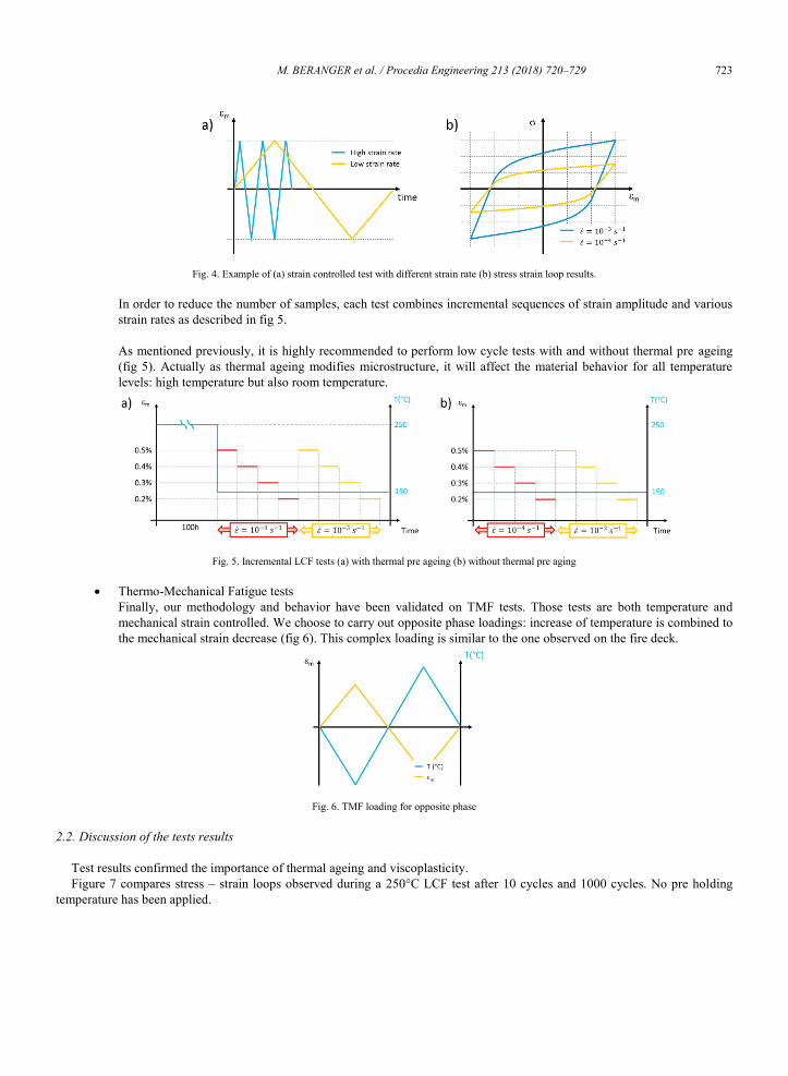
Incremental Low Cycle Fatigue tests LCF tests are commonly used to fit material behavior. In our case, we choose to carry out cyclic strain controlled tests (fig 4) with samples directly taken from the fire deck.
M. BERANGER et al. / Procedia Engineering 213 (2018) 720–729 7234 BERANGER, FIARD, CAILLETAUD, AMMAR / Fatigue Design (2017) 0022
Fig. 4. Example of (a) strain controlled test with different strain rate (b) stress strain loop results.
In order to reduce the number of samples, each test combines incremental sequences of strain amplitude and various strain rates as described in fig 5. As mentioned previously, it is highly recommended to perform low cycle tests with and without thermal pre ageing (fig 5). Actually as thermal ageing modifies microstructure, it will affect the material behavior for all temperature levels: high temperature but also room temperature.
Fig. 5. Incremental LCF tests (a) with thermal pre ageing (b) without thermal pre aging
Thermo-Mechanical Fatigue tests Finally, our methodology and behavior have been validated on TMF tests. Those tests are both temperature and mechanical strain controlled. We choose to carry out opposite phase loadings: increase of temperature is combined to the mechanical strain decrease (fig 6). This complex loading is similar to the one observed on the fire deck.
Fig. 6. TMF loading for opposite phase
2.2. Discussion of the tests results
Test results confirmed the importance of thermal ageing and viscoplasticity. Figure 7 compares stress – strain loops observed during a 250°C LCF test after 10 cycles and 1000 cycles. No pre holding
temperature has been applied.

724 M. BERANGER et al. / Procedia Engineering 213 (2018) 720–729 Author name / Procedia Engineering 00 (2017) 000–000 5
Fig. 7. Stress-strain loop on new sample at 250°C after 10 cycles and 1000 cycles
First analysis could conclude to an isotropic softening instead of thermal ageing effect. However, at that temperature level, thermal ageing is relevant and develops during the test to reach its asymptotic value after
50 hours. It can be illustrated by comparison of the first loops with and without thermal ageing at 250°C (fig 8).
Fig. 8. First stress-strain loop at 250°C on a new sample and on a pre aged sample (100h at 250°C)
Finally the softening effect comes from thermal ageing effect instead of an isotropic softening linked to the deformation process.
The same effect can be observed for low temperature LCF tests. Actually fig 9 compares the first stress – strain loops at 20°C for specimens with and without thermal pre-aging at 250°C.
Fig. 9. Stress-strain loop at 20°C on a new sample and on a pre-aged sample (100h at 250°C)
As expected, thermal ageing changes both yield stress and kinematic hardening (note that in that case only the dwell time at 250°C activates thermal ageing).

M. BERANGER et al. / Procedia Engineering 213 (2018) 720–729 7256 BERANGER, FIARD, CAILLETAUD, AMMAR / Fatigue Design (2017) 0022
2.3. Material behavior model
For the sake of simplify, the mathematical model is expressed for uniaxial loading, such as those on normative tests. For 3D general model, the reader can refer to [5].
Material behavior is given by the following equations Strain partition : 𝜀𝜀𝑚𝑚 = 𝜀𝜀𝑒𝑒 + 𝜀𝜀𝑝𝑝 (1) Elastic constitutive equation : 𝜎𝜎 = 𝐸𝐸. 𝜀𝜀𝑒𝑒 (2) Non elastic constitutive equation given by the visco plastic flow :
)( XsignK
RXn
Yp
(3)
With Y the yield stress partly affected by thermal ageing :
𝜎𝜎𝑌𝑌 = 𝑅𝑅0 + (1 − 𝑎𝑎). 𝑅𝑅0∗ (4) X the nonlinear kinematic hardenings with only one affected by thermal ageing :
𝑋𝑋 = 𝑋𝑋1 + (1 − 𝑎𝑎). 𝑋𝑋2 (5) With Xi in each branch : 𝑋𝑋𝑖𝑖 = 𝜈𝜈 𝐶𝐶𝑖𝑖
𝐷𝐷𝑖𝑖+ (𝑋𝑋1,0 − 𝜈𝜈 𝐶𝐶𝑖𝑖
𝐷𝐷𝑖𝑖) . 𝑒𝑒−𝜈𝜈𝐷𝐷𝑖𝑖(𝜀𝜀𝑝𝑝−𝜀𝜀𝑝𝑝0) (6)
And = sign( - X) (7) R the isotropic hardening :
𝑅𝑅 = 𝑄𝑄(1 − 𝑒𝑒−𝑏𝑏.𝑝𝑝) (8) That behavior introduces the thermal ageing function [1, 3, 4], a(t), given by the following equation :
aTaa (9)
Where ⟨ ⟩ is the positive part function.
12 temperature dependent parameters (𝑘𝑘, 𝑛𝑛, 𝑅𝑅0, 𝑅𝑅0∗, 𝑄𝑄, 𝑏𝑏, 𝐶𝐶1, 𝐷𝐷1, 𝐶𝐶2, 𝐷𝐷2, 𝑎𝑎∞, 𝜏𝜏) have been calibrated using ZEBULON-ZOPT software [6]. Young modulus is pre calibrated on tensile tests and fitted on stabilized stress-strain loop.
The accuracy of that model is then validated on different TMF tests. The next figure (fig 10) compares stress-strain loop
estimated and observed after 100 cycles for two opposite loadings from 50°C to 250°C. The development of thermal ageing during the test impacts directly the hysteresis loop.
Fig. 10. Example of material behavior accuracy on TMF test after 100 cycles
2.4. Discussions about the model
The following table lists the Pareto of each contribution on maximum stress reached.
Table 2 : Pareto of stress contribution on maximum stress
Temperature Yield stress
(𝑅𝑅0 + 𝑅𝑅0∗) Visco plastic stress
𝐾𝐾(𝜀𝜀�̇�𝑝)1 𝑛𝑛⁄
Kinematic hardening
(𝑋𝑋1 + 𝑋𝑋2) Thermal ageing effect
T = 20°C 40% 7% 50% 0%
T = 150°C 33% 30% 37% 0%
T = 200°C 32% 30% 27% 11%
T = 250°C 27% 23% 18% 32%
3 physical phenomena compete within temperature:

726 M. BERANGER et al. / Procedia Engineering 213 (2018) 720–729 Author name / Procedia Engineering 00 (2017) 000–000 7
At low temperature (T < 150°C), the higher stress contribution comes from kinematic hardening At medium temperature (150°C < T < 200°C), from visco-plasticity At high temperature (T > 200°C), from thermal ageing
Thermal ageing is active for temperature higher than 150°C. The main consequence regarding cylinder head is the following
For areas with T < 150°C, material behavior will be more classical visco-plastic model with two nonlinear kinematic hardenings (1). In a tensile test, the stress writes:
𝜎𝜎 = (𝑅𝑅0 + 𝑅𝑅0∗) + 𝑅𝑅 + (𝑋𝑋1 + 𝑋𝑋2) + 𝐾𝐾(𝜀𝜀�̇�𝑝)1 𝑛𝑛⁄ (10)
For areas which undergo higher temperature, even in a transient way, thermal ageing should be considered. Analyzing the thermal distribution on cylinder head, ageing mainly affects fire deck and exhaust ducts.
Fig. 11. Thermal distribution on cylinder head (maximum temperature reached)
That conclusion is very important for Finite Element simulation. Indeed, cylinder head simulations are particularly time consuming: FE model takes into account many parts, contacts, nonlinear material behavior. Therefore current High Performance Calculation allows us to simulate only a few cycles which is not consistent with the time scale of thermal ageing.
Furthermore, the real test bench duration ranges from 400 hours to 800 hours, depending on engine, fuel and type of vehicle. Therefore, at the end of the test bench, the fire deck material will have saturated its thermal ageing.
Based on those two points, Renault’s strategy consists in performing global simulation of cylinder head with new material (i.e.
without thermal ageing) and local simulation such as fire deck with a material with saturated thermal ageing.
3. Fatigue criteria
3.1. Discussion on tests conditions and results
According to Barlas [1], creep fatigue damage should be considered for this type of aluminum-silicon alloy. To fit such a model, 3 kinds of tests are necessary:
Pure fatigue tests (LCF at high strain rate), Combined creep-fatigue tests (LCF with tensile dwell time, fig 12),
Fig. 12. Creep Fatigue tests
Fatigue tests with low strain rate, TMF tests described in the previous chapter.
For the same reason previously noticed, we will estimate the effect of thermal ageing by adding, for some conditions, a preheating period at 200°C or 250°C before the beginning of the test.

M. BERANGER et al. / Procedia Engineering 213 (2018) 720–729 7278 BERANGER, FIARD, CAILLETAUD, AMMAR / Fatigue Design (2017) 0022
Fig 13 represents, for each level of temperature, the lifetime results as a function of the half range of the simulated stress (/2) normalized by the Ultimate Tensile Stress at 20°C (UTS).
Fig. 13. Lifetime results on S-N curves (a) effect of temperature (b) effect of thermal ageing
The main conclusions of that first analysis are the following: Dispersion of the data is too large to consider that the stress range is the only relevant fatigue criterion, Lifetime models have to take into account temperature dependency, Thermal ageing seems to impact lifetime.
Regarding the effect of creep-fatigue damage, conclusions are not so easy. As shown in the figure 14, the variability induced by creep fatigue depends on temperature level and seems to be lower than other effects.
It can be explained by the fact that creep damage is hardly discriminated from ageing: when a dwell period is added in a test, the ageing level at a given number of cycles will be larger than for the reference continuous fatigue loading, then the stress level will be lower. The result in terms of lifetime depends then on the relative evolution of the stress strain behavior (ageing) and of the life prediction model (creep damage). Facing such a complex situation, a pragmatic solution is to account for both ageing and creep by means of the evolution of a material parameter in the fatigue damage model, as explained in the following section.
Fig. 14. Creep fatigue effect at high temperature
3.2. Stress based fatigue model
A Low Cycle Fatigue criterion is used to estimate lifetime of a fire deck, for a typical loading between room temperature and maximum power temperature, with a 3D Finite Element model. A damage estimation on fire deck inter-valves bridge is also performed with a simplified 1D mechanical model.
Renault’s experience has shown that a normalized stress based model [1, 3, 7] is particularly well adapted to those issues. It is assumed that creep effect is included in the parameter evolution due to temperature and thermal ageing. This assumption is reinforced by the fact that low strain rate data such as TMF and LCF at 10-4s-1 are used for the identification of the fatigue model.
In the following, the stress tensor is normalized with a temperature and thermal ageing dependent scale function 𝜎𝜎𝑢𝑢(𝑇𝑇, 𝑎𝑎) :
𝑆𝑆 = 𝜎𝜎𝜎𝜎𝑢𝑢(𝑇𝑇, 𝑎𝑎)⁄ (11)
Applied to uniaxial loading, lifetime is then given by the following formula
𝑁𝑁𝑓𝑓 =1
(𝛽𝛽+1) . ⟨1−𝑆𝑆𝑚𝑚𝑚𝑚𝑚𝑚S𝑚𝑚−𝑆𝑆𝑙𝑙0
⟩ . (S𝑚𝑚𝑀𝑀0)−𝛽𝛽
(12)
Where Sa is the amplitude of the normalized stress, Smax its maximum along the cycle, Sl0 the normalized fatigue limit l0 for a
load ratio equal to -1, and where: M0, Sl0 and are 3 material parameters independent of temperature and ageing.
728 M. BERANGER et al. / Procedia Engineering 213 (2018) 720–729 Author name / Procedia Engineering 00 (2017) 000–000 9
Calibration of the model is split into two steps: scale function estimation followed by estimation of the 3 constant M0, Sl0 and
. For the first part, we assume that 𝜎𝜎𝑢𝑢(𝑇𝑇, 𝑎𝑎) is a bilinear function calibrated with UTS dependency within temperature and
effect of thermal ageing on ultimate stress simulated with the material behavior. The 3 last parameters are estimated regarding the above assessments:
Sl0 is the ratio between fatigue limit at room temperature, for a load ratio R=-1 and UTS at room temperature, is fitted on pure fatigue tests (i.e. LCF tests with high strain rate 𝜀𝜀̇ = 10−2𝑠𝑠−1), M0 is adapted to TMF data and LCF test with low strain rate.
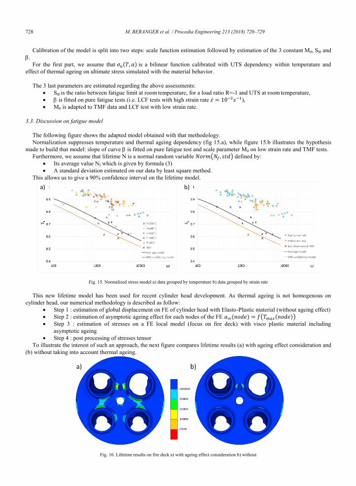
3.3. Discussion on fatigue model
The following figure shows the adapted model obtained with that methodology. Normalization suppresses temperature and thermal ageing dependency (fig 15.a), while figure 15.b illustrates the hypothesis
made to build that model: slope of curve is fitted on pure fatigue test and scale parameter M0 on low strain rate and TMF tests. Furthermore, we assume that lifetime N is a normal random variable 𝑁𝑁𝑁𝑁𝑁𝑁𝑁𝑁(𝑁𝑁𝑓𝑓, 𝑠𝑠𝑠𝑠𝑠𝑠) defined by:
Its average value Nf which is given by formula (3) A standard deviation estimated on our data by least square method.
This allows us to give a 90% confidence interval on the lifetime model.
Fig. 15. Normalized stress model a) data grouped by temperature b) data grouped by strain rate
This new lifetime model has been used for recent cylinder head development. As thermal ageing is not homogenous on cylinder head, our numerical methodology is described as follow:
Step 1 : estimation of global displacement on FE of cylinder head with Elasto-Plastic material (without ageing effect) Step 2 : estimation of asymptotic ageing effect for each nodes of the FE 𝑎𝑎∞(𝑛𝑛𝑁𝑁𝑠𝑠𝑛𝑛) = 𝑓𝑓(𝑇𝑇𝑚𝑚𝑚𝑚𝑚𝑚(𝑛𝑛𝑁𝑁𝑠𝑠𝑛𝑛)) Step 3 : estimation of stresses on a FE local model (focus on fire deck) with visco plastic material including
asymptotic ageing Step 4 : post processing of stresses tensor
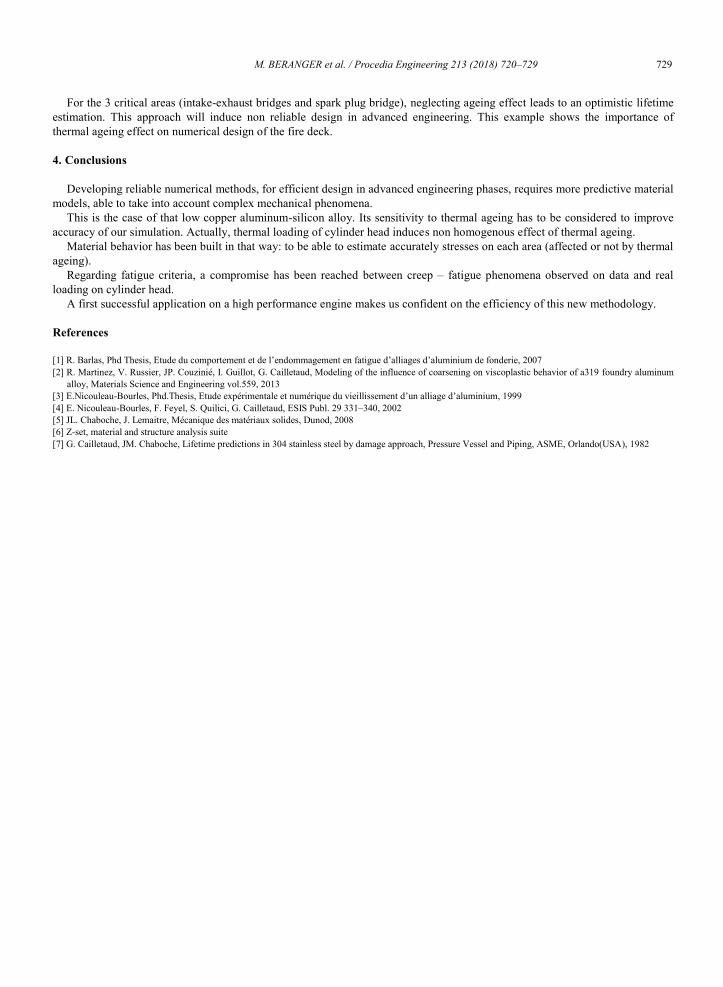
To illustrate the interest of such an approach, the next figure compares lifetime results (a) with ageing effect consideration and (b) without taking into account thermal ageing.
Fig. 16. Lifetime results on fire deck a) with ageing effect consideration b) without
M. BERANGER et al. / Procedia Engineering 213 (2018) 720–729 72910 BERANGER, FIARD, CAILLETAUD, AMMAR / Fatigue Design (2017) 0022
For the 3 critical areas (intake-exhaust bridges and spark plug bridge), neglecting ageing effect leads to an optimistic lifetime estimation. This approach will induce non reliable design in advanced engineering. This example shows the importance of thermal ageing effect on numerical design of the fire deck.
4. Conclusions
Developing reliable numerical methods, for efficient design in advanced engineering phases, requires more predictive material models, able to take into account complex mechanical phenomena.
This is the case of that low copper aluminum-silicon alloy. Its sensitivity to thermal ageing has to be considered to improve accuracy of our simulation. Actually, thermal loading of cylinder head induces non homogenous effect of thermal ageing.
Material behavior has been built in that way: to be able to estimate accurately stresses on each area (affected or not by thermal ageing).
Regarding fatigue criteria, a compromise has been reached between creep – fatigue phenomena observed on data and real loading on cylinder head.
A first successful application on a high performance engine makes us confident on the efficiency of this new methodology.
References
[1] R. Barlas, Phd Thesis, Etude du comportement et de l’endommagement en fatigue d’alliages d’aluminium de fonderie, 2007 [2] R. Martinez, V. Russier, JP. Couzinié, I. Guillot, G. Cailletaud, Modeling of the influence of coarsening on viscoplastic behavior of a319 foundry aluminum
alloy, Materials Science and Engineering vol.559, 2013 [3] E.Nicouleau-Bourles, Phd.Thesis, Etude expérimentale et numérique du vieillissement d’un alliage d’aluminium, 1999 [4] E. Nicouleau-Bourles, F. Feyel, S. Quilici, G. Cailletaud, ESIS Publ. 29 331–340, 2002 [5] JL. Chaboche, J. Lemaitre, Mécanique des matériaux solides, Dunod, 2008 [6] Z-set, material and structure analysis suite [7] G. Cailletaud, JM. Chaboche, Lifetime predictions in 304 stainless steel by damage approach, Pressure Vessel and Piping, ASME, Orlando(USA), 1982