a new experiment to search for hidden particles (ship) at...
TRANSCRIPT

EDMS NO. REV. VALIDITY
1369559 1.0 RELEASED
REFERENCE
EN-DH-2014-007
Date : 2014-07-02
CERN CH1211 Geneva 23
Switzerland
Report
A new Experiment to Search for Hidden
Particles (SHIP)
at the SPS North Area
Preliminary Project and Cost Estimate
The scope of the recently proposed experiment Search for Heavy Neutral Leptons, EOI-010,
includes a general Search for HIdden Particles (SHIP) as well as some aspects of neutrino
physics. This report describes the implications of such an experiment for CERN.
DOCUMENT PREPARED BY: DOCUMENT CHECKED BY: DOCUMENT APPROVED BY:
G.Arduini, M.Calviani,
K.Cornelis, L.Gatignon,
B.Goddard, A.Golutvin,
R.Jacobsson, J. Osborne,
S.Roesler, T.Ruf, H.Vincke,
H.Vincke
S.Baird, O.Brüning,J-P.Burnet,
E.Cennini,P.Chiggiato, F.Duval,
D.Forkel-Wirth,
R.Jones, M.Lamont, R.Losito,
D.Missiaen,
M.Nonis, L.Scibile,
D.Tommasini,
F.Bordry, P.Collier,
M.J.Jimenez, L.Miralles,
R.Saban, R.Trant

REFERENCE EDMS NO. REV. VALIDITY
EN-DH-2014-007 1369559 1.0 RELEASED
Page 2 of 81
HISTORY OF CHANGES
REV. NO. DATE PAGES DESCRIPTIONS OF THE CHANGES
0.0
2014-03-23 12 Assembly of first contributions from G.Arduini, K.Cornelis,
L.Gatignon, B.Goddard A.Golutvin, R.Jacobsson, T.Ruf.
0.1 2014-03-27 12 First review L.Gatignon, R.Jacobsson to introduce SHIP
0.1 2014-03-27 21 With the contribution of J.Osborne
0.2 2014-04-01 27 With the contribution of M. Calviani, A. Ferrari, R. Losito,
A. Perillo-Marcone, R. Folch, V. Venturi
0.3
0.4
0.5
0.6
0.7
1.0
2014-04-02
2014-04-29
2014-05-16
2014-05-28
2014-06-13
2014-07-02
33
56
63
87
81
81
With the contribution of Doris Forkel-Wirth, Stefan Roesler,
Heinz Vincke, Helmut Vincke
With the contribution of Brennan Goddard and significant
revisions of all others.
Updates in all sections, with agreed and consistent layout.
Includes significantly revised description of target and revised
radiation protection section. Preliminary cost estimates and
timeline have been added.
Add executive summary and expand introduction. Complete
estimate for costs and resources and updated timeline. Added
input to cost and resource estimates as an appendix.
Include comments from authors and checkers to version 0.6.
This includes some updates to the resources.
Add manpower to resource estimates in executive summary,
correct last paragraph of introduction accordingly and correct
FTEs in Appendix II-2. Small typographic corrections. Font
consistency in Appendix II.

REFERENCE EDMS NO. REV. VALIDITY
EN-DH-2014-007 1369559 1.0 RELEASED
Page 3 of 81
Executive Summary
The proposed SHIP experiment is a new general-purpose fixed target facility at the
SPS to search for hidden particles as predicted by a very large number of recently
elaborated models of Hidden Sectors which are capable of accommodating dark
matter, neutrino oscillations, and the origin of the full baryon asymmetry in the
Universe. Moreover, the facility is ideally suited to study the interactions of tau
neutrinos. The SHIP detector consists of two 40 m long evacuated decay volumes,
each of which is followed by a 10m magnetic spectrometer, a calorimeter and muon
detectors. An emulsion target surrounded by a magnetic field is located upstream of
the decay volumes.
The SPS configuration and performance have been investigated under the assumption
that SHIP shares the protons with the current North Area fixed target program in a
way similar to CNGS. The performance of the ZS septa and the induced radioactivity in
the SPS extraction region are likely to be key factors in the overall SHIP performance
and require further studies. Realistic super-cycle compositions have been elaborated
using past experience for the operation of the North Area, CNGS and LHC, and MDs.
The dedicated SHIP beam line branches of at the top of the existing TT20, in the TDC2
cavern. With a two-polarity splitter magnet replacing the current splitter, an extra
beam line is possible. The production target is very challenging due to the very high
energy and power density. Preliminary investigations show that required performance
may be achieved with a 50 cm water cooled and segmented tungsten target
embedded in a massive iron shielding that also acts as a hadron stopper. The target
and the 5 m hadron stopper are followed by a 70 m long muon filter. The beam line is
followed by a 120 m long and 20 m wide underground detector hall, which houses the
SHIP detector and the emulsion target.
Although uncertainties persist at this preliminary design stage, the overall material
cost of the beam and infrastructure is estimated to be about 114 MCHF and the
manpower required is estimated to be 91 FTEs. The detectors themselves have an
estimated cost of about 45 MCHF. The junction cavern with TDC2 has to be
constructed and equipped during Long Shutdown 2. The aim is to start beam
commissioning and operation during Run 3, i.e. around 2023.

REFERENCE EDMS NO. REV. VALIDITY
EN-DH-2014-007 1369559 1.0 RELEASED
Page 4 of 81
TABLE OF CONTENTS
A new Experiment to Search for Hidden Particles (SHIP) at the SPS North Area .................... 1
Preliminary Project and Cost Estimate .............................................................................. 1
Executive Summary ....................................................................................................... 3
1. Introduction ............................................................................................................ 5
2. Experimental motivation and requirements ................................................................. 7 2.1 Physics scope ................................................................................................... 7 2.2 Operational Requirements .................................................................................. 9 2.3 Experimental setup and detector configuration .................................................... 10
3. The Experimental Area Considerations ..................................................................... 12 3.1 The basic layout .............................................................................................. 12 3.2 The secondary ‘beam line’ ................................................................................ 13 3.3 Infrastructure requirements .............................................................................. 15 3.4 Compatibility with the rest of the SPS fixed target program .................................. 15
4. Beam Parameters for the SHIP Experiment ............................................................... 16
5. Beam extraction, transfer and dilution ...................................................................... 25
6. SHIP Target and Target Station Design .................................................................... 32 6.1 Introduction ................................................................................................... 32 6.2 Target design ................................................................................................. 33 6.3 Target station design ....................................................................................... 36
7. Civil Engineering for the SHIP experiment ................................................................. 41 7.1 Overview ........................................................................................................ 41 7.2 Civil Engineering ............................................................................................. 42
8. Preliminary radiation protection considerations for SHIP ............................................. 50 8.1 Radiation levels in TDC2 ................................................................................... 51 8.2 Prompt dose rate around the SHIP target ........................................................... 52 8.3 Preliminary shielding requirement around the SHIP target .................................... 54 8.4 Handling of the SHIP target .............................................................................. 55 8.5 Muon shielding ................................................................................................ 56
9. Timeline and Resources .......................................................................................... 58

REFERENCE EDMS NO. REV. VALIDITY
EN-DH-2014-007 1369559 1.0 RELEASED
Page 5 of 81
1. Introduction
At its meeting on Tuesday February 4th, the Enlarged Directorate took the decision to
convene a joint study group between the Accelerator Sector, members of the team
which made the proposal for an experiment to Search for Hidden Particles (SHIP), and
the HSE unit to prepare a report including the layout, the timeline and the resources
which are required to set-up the experiment. The task force met on 4 occasions and
prepared this preliminary report for the DG in order to enable him to assess the
implications of such an experiment at the SPS.
The proposed SHIP experiment is a new general-purpose fixed target facility at the
SPS to search for hidden particles. These are predicted by a very large number of
recently elaborated models of Hidden Sectors which are capable of accommodating
dark matter, neutrino oscillations, and the origin of the full baryon asymmetry in the
Universe. The high intensity of the SPS and in particular the large production of charm
mesons with the 400 GeV beam allow accessing a wide variety of light long-lived
exotic particles of such models and of SUSY. Moreover, the facility is ideally suited to
study the interactions of tau neutrinos.
The SHIP detector consists of two 40 m long evacuated decay volumes, each of which
is followed by a 10 m magnetic spectrometer, a calorimeter and muon detectors in
order to allow full reconstruction and particle identification, together with an upstream
emulsion target. As an example, with an integrated total of 2x10²⁰ protons on target,
the experiment achieves sensitivity for heavy neutral leptons that is four orders of
magnitude better than previous searches, accessing a significant fraction of the
unexplored parameter space consistent with cosmological constraints.
The SPS configuration and performance have been investigated under the assumption
that SHIP shares the protons with the current North Area fixed target program in a
way similar to CNGS. At the start-up of SHIP aimed at 2023, the fixed target operation
will need to return to a longer flat top and slightly reduced duty cycle as during CNGS
operation to accommodate the SHIP cycles. The baseline extraction will be a slow
resonant extraction to TT20 with a 1 to 2.2 seconds long flat top at ~400 GeV/c. In
these conditions, the findings allow considering a beam intensity of 4x10¹³ p/cycle as
the baseline for the design of the critical components like the target, cooling, detectors
and the general layout of the civil engineering works. The performance of the ZS septa
and the induced radioactivity in the SPS extraction region are likely to be key factors
in the overall SHIP performance and require further studies.
Realistic super-cycle compositions have been elaborated using the experience and
schedule from 2011 and 2012 for the operation of the North Area, CNGS and LHC, and
MDs. As an example of an operational scenario the delivery of 4 x10¹⁹ protons per
year on the SHIP target is feasible with a 40% reduction of the beam availability for
the North Area fixed-target program from 2023 as compared to entirely dedicated
operation. Thus the projected integrated flux of 2x10²⁰ protons on target can be
provided over 5 years of fully efficient operation in conditions which may be

REFERENCE EDMS NO. REV. VALIDITY
EN-DH-2014-007 1369559 1.0 RELEASED
Page 6 of 81
considered nominal. Ultimately, the super-cycle optimization will be based on a
physics trade-off between SHIP and the North Area programs at the time of start-up,
but also technical arguments such as the limits of the SPS extraction septa and the
optimal target design. An ultimate scenario with an SPS intensity of 7x10¹³ per cycle
has been explored. It would require major upgrades to the SPS.
The new dedicated SHIP beam line branches off at the top of the existing TT20, in the
TDC2 cavern. With a new two-polarity splitter magnet replacing the current splitter,
an extra beam line is possible, symmetric to the T6 beam line but to the left of the T2
line instead of to the right. A set of 10 additional dipole magnets will deflect the beam
out of TDC2 into a new 150m extraction tunnel onto the SHIP target. The beam line
up to the target is mainly composed of drift space apart from the critically important
beam dilution, implemented with a pair of orthogonal conventional magnets with a
fast Lissajous powering function.
The production target is one of the most challenging aspects of the proposed facility
due to the very high energy and power density. The preliminary investigations show
that required performance may be achieved with a 50 cm water cooled and
segmented tungsten target embedded in a massive iron shielding that also acts as a
hadron stopper. The results show that the projected operational conditions are not far
from the limits of pure tungsten. A vigorous R&D program on materials and target
configuration is therefore advocated.
A multi-compartment complex at 12 m depth respecting the radiological aspects has
been outlined. The target bunker and the storage zone are embedded inside a helium-
filled vessel atmosphere with online circulation and purification. Cooling and
ventilation of the installation, the target handling and access have been considered.
The target and the 5m hadron stopper are followed by a 70 m long muon filter located
in a tunnel at the same depth. The baseline design is a passive shielding with a 40 m
long 100 t tungsten core completed with 2500 t of lead. This allows reducing the
muon flux by the required six orders of magnitude. A potentially cheaper alternative
based on a combination of magnetic sweeping and passive shielding is under study.
Conceptual designs of all the elements above are presented in this document. Overall,
and despite some interesting challenges, the beam transfer, target and muon filter
requirements seem feasible. RP aspects are important and have been addressed
through preliminary simulations
The beam line is followed by a 120 m long and 20 m wide underground detector hall,
which houses the SHIP detector and the emulsion target.
The layout and implementation in the North Area is described in detail, including the
civil engineering aspects. The civil engineering studies were based on the assumption
that the SHIP facility will be sited on the CERN Prevessin laboratory in France. All civil
engineering works for the project are fully located within existing CERN land on the
Prevessin campus. This location is extremely well suited to housing the SHIP project,

REFERENCE EDMS NO. REV. VALIDITY
EN-DH-2014-007 1369559 1.0 RELEASED
Page 7 of 81
with the very stable and well understood ground conditions, and very limited
interference with the current building, galleries and road structure.
The infrastructure systems cost has been elaborated, even though at this stage no
detailed design is available everywhere. This includes in particular the electrical and
cooling and ventilation infrastructure systems, the access and safety systems and the
costs of cranes, lifts and handling costs. The estimates are based on the description
given in this report. In some cases the sizing and costs are rather based on similar
installations elsewhere.
Although uncertainties persist at this preliminary design stage, the overall material
cost of the beam and infrastructure is estimated to be about 114 MCHF and the
manpower required is estimated to be 91 FTEs. The detectors themselves have an
estimated cost of about 45 MCHF. The junction cavern with TDC2 has to be
constructed and equipped during Long Shutdown 2. The aim is to start beam
commissioning and operation during Run 3, i.e. around 2023.
2. Experimental motivation and requirements
2.1 Physics scope
The recent discovery of the Higgs boson with mass ~125.5 GeV implies that the
Standard Model (SM) may well be a self-consistent, weakly-coupled, effective field
theory all the way up to the Planck scale [1,2]. Nevertheless, it is clear that the SM is
incomplete since it does not provide an explanation for the observations of neutrino
oscillations, the excess of matter over antimatter in the Universe, and the presence of
non-baryonic dark matter. These shortcomings may have their origin in new physics
involving very weakly interacting particles such as predicted by models of portals to a
hidden sector with heavy Majorana leptons, dark photons etc, or in SUSY [3-8]. Given
the small coupling constants and typically long lifetimes, these new different particles
have not been significantly constrained by previous experiments, and the reach at
current collider experiments is limited by both luminosity and acceptance.
In this context, the current document pertains to a proposal of a general-purpose
fixed target facility at the SPS to search for hidden particles [9,10]. In particular, the
large production of charm mesons with the 400 GeV beam and the high intensity of
the SPS allow accessing a wide variety of light long-lived exotic particles. As a starting
point for the study of the sensitivity, the neutrino Minimal Standard Model (MSM) has
been used [11-16]. The MSM can account simultaneously for neutrino masses and
oscillations, baryogenesis, and dark matter. Figure 1 shows the expected sensitivity
for the heavy neutral leptons of the MSM model estimated with only the decay
mode. As shown, a significant fraction of the unexplored parameter space which is
consistent with cosmological constraints is accessible at the proposed facility.
As a second example here, the sensitivity to dark photons is shown in Figure 2. Dark
photons, or secluded photons ’, appear in a large class of dark matter models [17]

REFERENCE EDMS NO. REV. VALIDITY
EN-DH-2014-007 1369559 1.0 RELEASED
Page 8 of 81
and a large region of mass and coupling may be explored through ’ production in 0
decays and in ’ bremsstrahlung from the incoming proton beam.
The proposed detector is designed to fully reconstruct the exclusive decays of long-
lived particles. In order to minimize the model dependence in the search, the detector
incorporates dedicated particle identification in a wide range of momentum for
discrimination of as many different decay modes as possible. Such a facility would be
an essential complement to the LHC and the other fixed target programs in the search
for new physics at CERN.
Figure 1: Expected sensitivity in the proposed experiment to the mixing of
the Heavy Neutral Leptons with the muon neutrino compared with
cosmological constraints and current experimental upper bounds.
Figure 2: Expected sensitivity in the proposed experiment to dark photons
compared to present experimental bounds. The preliminary sensitivity is
based on the production mechanism through proton Bremsstrahlung and
photonic meson decays.

REFERENCE EDMS NO. REV. VALIDITY
EN-DH-2014-007 1369559 1.0 RELEASED
Page 9 of 81
The facility is also ideally suited for studying the energy threshold of interactions
and neutrino-induced charged-current charm production, as well as a first observation
of the ̅. It is expected that the sensitivity for interactions is at least 400 times
better that at previous experiments assuming that a 5m long compact tau neutrino
detector based on emulsion similar to OPERA is added to the setup.
2.2 Operational Requirements
The experiment requires a 400 GeV proton beam from the SPS with the aim of
producing a maximum number of charm mesons. The choice of the energy is driven
by an optimization between maximizing the charm cross-section and signal acceptance
with respect to the boost of the charm system, and minimizing the level of machine
induced background and minimizing the length of the filter required to reduce the
muon flux. In accordance with these requirements, the SPS provides the most
favourable experimental conditions.
The estimation of the experimental sensitivities to the various physics modes is based
on 21020 protons on target, which is assumed to be achievable in five years of full
operation. This is based on the starting point of a minimal modification to the existing
accelerator complex, a fully compatible shared operation with the current North Area
experimental program and the LHC, and dedicating a similar fraction of beam time as
was provided to the CNGS facility. Increased experimental reach could come as a by-
product of a future SPS upgrade. The design of the proposed experiment will allow
taking advantage of such a potential upgrade.
The large flux of muons and the requirement of accurate full reconstruction of both
background events and signal events favour the choice of a relatively long extraction
to reduce the detector occupancy per unit time. At the same time, the extraction type
should not affect significantly the SPS cycle time as compared to CNGS. A spill length
of 1.2 s would significantly ease the requirements on the detector and the
reconstruction, as well as on the target design, and would reduce the requirements on
the muon filter. Naively this would mean a 7.2 s SPS spill cycle, and consequently an
acceptable reduction of the number of protons on target by 10% with respect to the
CNGS operation. While the preference is a long extraction time with a profile which is
as squared as possible, the continuous high-rate readout means that the experiment
is not sensitive to time or momentum ripples in the extracted beam.
Since the particles of interest from the charm mesons decays have a significant polar
angle with respect to the beam direction, there is no requirement to have a small
beam spot as long as the bulk of the muon flux is contained within the aperture of the
muon filter. Hence, the beam line design can be driven purely by the technical
requirements and constraints.
For the same reason, the experiment does not impose stringent constraints on the
optical parameters of the extracted beam. The required level of dilution of the beam
energy deposition to satisfy the target requirements may therefore be obtained by

REFERENCE EDMS NO. REV. VALIDITY
EN-DH-2014-007 1369559 1.0 RELEASED
Page 10 of 81
allowing the transverse size of the beam to increase and by using a combination of
orthogonally deflecting kicker magnets to produce a sweep on the target.
2.3 Experimental setup and detector configuration
The production of the charm mesons is accompanied by copious direct production of
short-lived light resonances, pions and kaons, resulting in a large flux of muons as
well as neutrinos. Interactions of neutrinos and muons in the material near the
detection volume can produce long-lived V0 decays, such as neutral kaons, which can
decay in the detector fiducial volume and mimic signal events. To suppress neutrino-
induced V0 background events from the downstream end of the muon filter, the
neutrino flux from long-lived meson decays must be minimised at the source. This is
achieved by the use of a target material with the shortest possible interaction length.
A tungsten target with a length of the order of half a metre would suffice. The target
should be followed by a hadron absorber of a few metres length to absorb the residual
non-interacting protons and the hadronic and electromagnetic radiation generated in
the target in order to prevent exposition of the components of the muon filter and
other instruments to direct radiation. As part of the absorber, a concrete shielding wall
will close-off the very limited target bunker volume from the downstream muon filter
tunnel.
The task of the muon filter is to reduce the flux of muons, mainly originating from the
decays of prompt resonances in the target. Due to the relatively large production
angles of the particles of interest, the experimental set-up must balance the opposing
requirements of locating the detector as close as possible to the target while
accommodating a sufficiently long muon filter to reduce the muon flux and the muon-
induced background to an acceptable level. Two configurations are being pursued: a
purely passive filter or a combination of magnetic deflectors and passive shielding.
With a slow beam extraction and a plausible detector granularity and LHC speed
readout, the detector occupancy from the muon flux is not a critical design parameter.
The most stringent limit is given by the maximum rate of muons tolerated for each
exposure of the emulsion detector of 104/mm2. Assuming ten exposures for
21020 protons on target, this corresponds to a limit of <105 muons per spill (51013
protons on target) over the whole SHIP spectrometer surface. The remaining muon-
induced background is tagged by the use of the interaction tagger detector upstream
of each of the two decay volumes, and topological cuts such as the impact parameter
and the invariant mass.
In addition, the design of the muon filter must respect the radiological requirements.
The optimization of the muon filter therefore requires a full simulation of this filter, the
surrounding infra-structure and the detector, in consultation with the Radiation
protection Group.
The proposed detector, shown in Figure 3, aims at fully reconstructing the exclusive
decays of long-lived particles and at measuring their invariant mass. Identification of
decay modes with electrons, neutral and charged -mesons, and muons in the final

REFERENCE EDMS NO. REV. VALIDITY
EN-DH-2014-007 1369559 1.0 RELEASED
Page 11 of 81
state is required. Hence, the basic detector configuration consists of a 40 m long
decay volume followed by a 10 m long magnetic spectrometer and detectors for
particle identification. To reduce to a negligible level the background caused by
interactions of muons and neutrinos with the air inside the decay volume, a pressure
of less than 10−2 mbar will be required. In case of need this may be further decreased
by two orders of magnitude. A detector element therefore consists of a 50 m long
cylindrical vacuum vessel of 5 m diameter. A tracking station at the beginning of each
decay vessel will be used to veto charged particles entering the fiducial volume. The
first veto station together with a calorimetry-based interaction tagger detector at the
end of the muon shield will also identify and reject upstream neutrino interactions.
The spectrometer includes a 4 m long dipole magnet, two tracking stations upstream
of the magnet, and two tracking stations downstream of the magnet. An
electromagnetic calorimeter with good energy resolution and sufficiently high
granularity, and a muon detector are located behind each vacuum vessel for 0
reconstruction and lepton identification. The combined calorimeter and muon detector
have a length of about 2 m. All the detector components could be based on existing
technologies.
Figure 3: Layout of a SHIP detector
The use of two detector elements increases the geometric acceptance by 70%
compared to a single element. Therefore, the proposed detector will have two almost
identical detector elements resulting in a total length of about 110 m.
The study of physics is based on a compact neutrino detector in the form of a 5m
long emulsion and muon spectrometer which is located centred on the beam axis
directly downstream of the muon filter and upstream of the SHIP decay volumes. In
order to keep the excellent pattern recognition and precision of the emulsion
technique, one can tolerate about 300 interactions per brick. To satisfy this constraint
the emulsion needs to be exchanged each 2 x 10¹⁹ protons on target (i.e. a total of
ten successive exposures).

REFERENCE EDMS NO. REV. VALIDITY
EN-DH-2014-007 1369559 1.0 RELEASED
Page 12 of 81
3. The Experimental Area Considerations
The SHIP experiment requires a new beam line and a new experimental facility in the
North Area of the SPS. The requirements and layout are described below. The
projected nominal integrated flux of 2x10²⁰ protons on target can be provided over a
minimum of 5 years of fully efficient operation in conditions which may be considered
as nominal (from Section 4). In practice, including commissioning, upgrades and
possible extensions of the program, this means that the facility must be designed for
at least 10 years of operation.
3.1 The basic layout
The SHIP experiment requires an extraction from point 2 to the North Area via the
TT20 tunnel, from which the primary proton beam branches off at the level of the first
splitter. Normally this splitter, consisting of 3 MSSB magnets, deflects part of the
beam to the Salève side towards the T6 production target for the COMPASS beam line
and the straight beam continues towards a second splitter distributing the beam over
the EHN1 beams and NA62. This splitter must get an additional function to also switch
the beam towards the new facility on the Jura side. About 100 m downstream of the
splitter, strong dipole magnets will deflect the beam out of TDC2.
From here the beam drifts via an 85 m long junction cavern and a 170 m long tunnel
towards the heavy and dense production target for the SHIP secondary beam line. As
this tunnel will contain active elements, this tunnel must be ventilated and have an
access point located in the middle of the transfer tunnel. A beam loss monitor will
detect accidental losses of the beam near this access shaft. An associated surface
building houses the infrastructure systems for the transfer beam line.
A ~10 m long hadron absorber, made of iron, surrounds the target, made of tungsten.
In order to minimize activation by backscattering from the target, an upstream
shielding is required with only a narrow passage for the beam. The target itself is
located inside the hadron absorber, about 5 m upstream of the end of the absorber.
The target and hadron absorber are housed in a single ~12 m deep underground
compact cavern containing a helium volume to avoid oxidation and in particular
activation of air. Both the target and the hadron absorber are actively cooled,
probably via a water circuit that is cooled itself via a heat exchanger. In case of leaks
of the cooling system, the water is collected and pumped away from a sump.
Immediately downstream of the target and hadron absorber, a 70 m long tunnel
houses the muon filter. The first 20 m section has dimensions 8x10 m2 and includes
an access shaft in a surface building which is adjacent to the target station surface
building, and a common crane. This first 20 m tunnel section houses mainly passive
material and, optionally, a set of upstream sweeping magnets. For this reason a crane
is also needed in this first section. The subsequent 50 m of the muon filter tunnel up
to the experimental hall has dimension 5x5 m2 and contains only passive absorber
material. The muon filter tunnel is followed by the experimental hall which is 120 m
long and with a section 20x14.5 m2, and which is equipped with a 40 ton crane.

REFERENCE EDMS NO. REV. VALIDITY
EN-DH-2014-007 1369559 1.0 RELEASED
Page 13 of 81
By maintaining the entire beam line horizontal and at the same level as the switching
in TDC2, the experimental hall ends up conveniently at a depth which avoids most of
the radiation problems, even with magnetic sweeping, while still allowing easy direct
access from top without a shaft. As was recommended by the SPSC, this also leaves
open the option to reuse the tunnel and the hall for other types of experiments in the
future, e.g. for neutrinos or experiment similar to DIRAC, NA62 or COMPASS.
3.2 The secondary ‘beam line’
The target must be made of dense material, to stop the pions and kaons produced
before they decay into muons and neutrinos. The beam spot can and must be large to
minimize the risks of damage to the target. In order to fulfill the experimental
requirement of less than 105 muons / 5x10¹³ pot, the muon filter needs to provide
rejection power up to 350 GeV/c of incoming muon momentum, see Figure 4. For the
low momentum muons, rejection powers exceeding 106 are required.
Figure 4: Muon flux after target and hadron absorber per 5x10¹³ pot obtained
from Pythia8+Geant4 simulation.

REFERENCE EDMS NO. REV. VALIDITY
EN-DH-2014-007 1369559 1.0 RELEASED
Page 14 of 81
The muon filter is located in a dedicated tunnel, separated from the target cavern. The
current baseline design consists of a combination of tungsten and lead, where the
amount of tungsten is minimized to shield mainly the high momentum muons, which
are emitted from the target in a narrow cone. As shown in Figure 5, at a total length
of 70m, about 100 ton of tungsten and 2500 ton of lead will be needed.
Figure 5: Passive muon filter setup.
An alternative solution being considered is based on the use of a mixture of active and
passive shielding. The active shielding consists of conventional cheap dipole magnets
filled with iron providing a field of 1.8 T. Three of such magnets of 6 m length would
be needed to provide enough bending power up to the highest muon momenta,
~350 GeV/c. Low momentum muons bent back by the return field need to be stopped
by blocks of iron placed behind the magnets.
Preliminary studies for the active shielding have been performed, partly by the
detector team using GEANT and partly by the experimental areas team using the
HALO program. The latter studies show a potential reduction of the remaining muon
backgrounds by more than an order of magnitude in case H-shaped magnets with iron
filled gap replace the upstream 16 m of passive shielding. Such magnets can be
operated with very low current and power and may not even require water-cooling. In
that case all tungsten can be replaced by e.g. iron (or lead).
The HALO program is very useful for optimization and comparative studies, but the
final design must be fine-tuned and validated with a full simulation (GEANT and/or
FLUKA). However, the muon energy spectrum in the studies with the HALO program
differs significantly from the Pythia8/Geant4 simulation, while the magnetic field
description in the Geant4 simulation is very approximate. The Geant4 studies
performed by the detector team do not confirm a large improvement in the reduction
of the muon background, more iron would be required than used in the HALO
simulation to arrive at similar rates as with a full passive shielding. Further studies are
needed to understand the differences.
In case of magnetic shielding, provision must be made for eventual water-cooling and
comfort ventilation to allow possible interventions on the magnet. There is no
significant activation or radiation protection issue in this tunnel, apart from prompt
muon dose.

REFERENCE EDMS NO. REV. VALIDITY
EN-DH-2014-007 1369559 1.0 RELEASED
Page 15 of 81
The 120 m long detector hall immediately follows this relatively narrow tunnel. This
hall must be ventilated for temperature control and fresh air, but at this stage there is
no requirement from the RP point of view. It must be equipped with a 40-ton crane.
The hall houses the two decay volumes plus spectrometers and thus also two large
spectrometer magnets.
In principle the background requirements from the SHIP experiment are such that the
zone of the detectors will be compatible with the status of non-designated area.
However, on the side of the detectors, the prompt muon dose is allowed to be higher
and in future experiments the dose could be higher everywhere. Therefore it is
necessary to foresee access control also in this hall, like for all other tunnels and halls,
from the start. RP monitoring is and in future cases ventilation may become a RP
requirement.
3.3 Infrastructure requirements
The experimental hall shall be located not too far from the EHN1 hall, so that basic
infrastructure is available at not too large distances. The infrastructure shall include:
● Electrical infrastructure
● Cooling water
● Access control
● IT networks
● All the alarms (fire detection, gas detection, …)
Some surface buildings will be required. The target cavern needs associated space for
CV equipment and for the controls, for the access to the target volume, a shielded
buffer zone and a loading area. Also there must be a cask loading and storage area a
few meters underground where used targets can be stored. An access shaft will be
required for the upstream section of the muon shield tunnel. Above the detector hall
there must be a surface building with top access to the underground hall, and
including a control room and associated facilities.
3.4 Compatibility with the rest of the SPS fixed target program
The presently anticipated fixed target program at the SPS comprises COMPASS in
EHN2, NA62 in ECN3, and NA61 plus test beams in EHN1. The so-called AWAKE facility
is under construction in the CNGS cavern. It is assumed that these experimental
facilities will also have running experiments beyond LS2. Therefore it is wise to design
a beam extraction and primary beam transport that remains compatible with the long-
term operation of these facilities. It is for the moment foreseen to replace the first
splitter by laminated magnets which can serve as a splitter during fixed target
operation in the North Area and can be used as a switch to send the protons towards
the Jura side for SHIP operation on a cycle-by-cycle basis. A beam tunnel has to be
constructed and connected to TCC2. At the junction, a cavern will be necessary,
because of the length of the passage of the beam through the TCC2 side wall.

REFERENCE EDMS NO. REV. VALIDITY
EN-DH-2014-007 1369559 1.0 RELEASED
Page 16 of 81
The extraction will preferably be a slow extraction with a flat top that must be a
compromise between low occupancy and survival of the target and the other
components (hence as long as possible) and on the other hand keeping the heat loss
on the SPS and transfer line acceptable and the repetition rate as high as possible.
Normally the SPS is operated with a 4.8s flat top with roughly a 15s repetition rate,
resulting in a ~30% duty cycle. In order to maintain a vigorous fixed target program
in the existing North Area in parallel to the operation of the SHIP facility, it seems
appropriate to go back to a long flat top (9.6 s) for the North Area and a 22% duty
cycle, like it was done during CNGS operation. It should be pointed out that in this
case more protons per spill are required for the North Area. This would lead to
increased losses and probably to a shortage of protons in case e.g. NA62 and
COMPASS would run simultaneously.
4. Beam Parameters for the SHIP Experiment
The maximum beam intensities accelerated so far and extracted from the SPS (peak
values) in the last 20 years are listed below:
● 4.8x10¹³ p/cycle (1997 – Slow+Fast Slow extraction – 9.6 s – 450 GeV/c)
● 4.5x10¹³ p/cycle (2008 – CNGS – Fast extraction – 6 s – 400 GeV/c)
● 4x10¹³ p/cycle (2009 – slow extraction – 15.6 s – 400 GeV/c)
The maximum intensity accelerated during machine studies (but not extracted) has
been 5.3x10¹³ p/cycle (2004).
From the above we consider that a beam intensity of 4.5x10¹³ p/cycle can be
reasonably assumed as baseline for the design of major/critical components like the
dilution, target, its cooling system, detectors and the general layout of the civil
engineering works. An “Ultimate” intensity of 7x10¹³ p/cycle can be considered as the
very maximum for the same design. However, at present there is no approved
construction project to increase the SPS Fixed Target (FT) beam intensity to this level,
and any benefits which might arise as side effects from the LHC Injectors Upgrade
program for the LHC beams will surely need to be supplemented by other measures to
control beam losses both in the SPS and the PS and the transfer lines. The ultimate
scenario is based on the target to accelerate up to 7x10¹³ p/cycle being studied in the
frame of the LAGUNA/LBNO and it is for the moment hypothetical.
Among the possible extraction methods considered (fast extraction, fast-slow
extraction on half-integer, slow extraction on third integer, multi-turn extraction) the
slow extraction on the third integer to TT20 in the time scale of 1 second is retained
as preliminary baseline for the beam parameters taken into account the following
considerations:
● Maximum acceptable instantaneous particle flux at the detector
● Preliminary estimates of the power and power density deposition on the target
SHIP assumes a proton beam of 400 GeV/c. This beam momentum corresponds to the
momentum of the proton beam extracted to the North target T2, T4 and T6 during

REFERENCE EDMS NO. REV. VALIDITY
EN-DH-2014-007 1369559 1.0 RELEASED
Page 17 of 81
proton fixed target operation. Machine Protection considerations require defining
different extraction momenta for the beams circulating in the SPS according to their
destination to allow proper interlocking. For that reason the momentum of the proton
beam extracted from the SPS for SHIP should differ from 400 GeV/c by at least 5
GeV/c: 395 GeV/c or 405 GeV/c are proposed as possible energies.
The minimum cycle length that is compatible with the above parameters is 7.2 s
provided that it can be proven that an extraction of 4.5x10¹³ p/cycle over ~1 s can be
performed without damaging the electrostatic septa or significantly increasing the
spark rate. An increase of the flat-top length to 2.4 seconds or even longer might be
required if the instantaneous rate of extracted protons is not compatible with a safe
operation of the electrostatic septa. In particular we consider a flat-top length of 2.4 s
for ultimate beam parameters.
The maximum acceptable average resistive power dissipated in the main magnets for
the SPS is 39 MW. This constraint limits the possible super-cycle combinations.
Realistic super-cycle compositions are considered in the following both to estimate the
expected integrated number of protons on target for the SHIP experiment and for the
experiments served by the TCC2 targets in a typical year and to determine a realistic
value of the average rate of protons on target and the average power deposited on
the target.
The average power dissipated in the main magnets for the main cycles composing the
SPS super-cycles during operation of the SPS for SHIP and for the fixed target
experiments in the North Area as well as for LHC filling are listed below in Table 1. The
cycles considered are based on the CNGS cycle used in 2011-2012 and the flat-top
(limited to 300 ms for CNGS) has been increased in steps of 1.2 s (present basic
period of the PS-SPS complex) to estimate the power consumption. Two cycles have
been considered for the SHIP experiment:
a cycle with flat-top length of 1.2 s (in the following called SHIP nominal) and
allowing an effective spill length of 1 s;
a cycle with flat-top length of 2.2 s (in the following called SHIP ultimate) and
allowing an effective spill length of 2 s.
The flat-top duration of the cycles dedicated to fixed target physics with the TCC2
targets must be of the order of 9 s to profit of the maximum number of protons that
can be accelerated per cycle in the SPS to 400 GeV/c compatible with the maximum
event rate acceptable at present by the North Area experiments and with the thermo-
mechanical stress of the splitter magnets. In this way the number of protons on the
TCC2 targets has been maximized during CNGS operation [18][19]. The cycle
considered for this operation is indicated with FT.
The cycles used for LHC set-up and filling are also listed and indicated with LHC pilot
and LHC nominal, respectively. Two low energy cycles have been included:
MD cycle used for machine studies (typically at 26 GeV/c) in parallel to fixed
target operation during normal working hours

REFERENCE EDMS NO. REV. VALIDITY
EN-DH-2014-007 1369559 1.0 RELEASED
Page 18 of 81
ZERO cycle: a low energy cycle (here assumed 14 GeV/c) that could be used to
reduce the average power consumption and keep it below the maximum value of
39 MW.
Cycle Cycle duration [s] Power [MW]
SHIP-nominal (1.2 s flat-top) – 400 GeV/c 7.2 32.5
SHIP-ultimate (2.2 s flat-top) – 400 GeV/c 8.4 38.5
FT (9.7 s flat-top) – 400 GeV/c 15.6 63.6
LHC nominal – 450 GeV/c 21.6 16.7
LHC pilot – 450 GeV/c 7.2 41.3
MD – 26 GeV/c 4.8 0.3
ZERO – 14 GeV/c 1.2 0.1
FT 2014 (4.9 s flat-top) 10.8 52.2
Table 1: Cycle duration and power consumption for the possible SPS cycles during the operation for SHIP.
For comparison the cycle for fixed target physics on the TCC2 targets to be used in
2014 is also listed (FT 2014). It is expected to extract up to 3.3x10¹³ p/cycle for this
mode of operation.
In the above a momentum of 400 GeV/c has been considered both for the SHIP and
FT cycles. Indeed the momentum of the proton beam delivered to the SHIP target
should differ from 400 GeV/c by at least 5 GeV/c for machine protection
considerations. This will not change significantly the conclusions.
Operation of SHIP will occur in parallel to:
LHC operation;
Fixed Target physics operation for the other TCC2 targets;
Parallel Machine Development programme (during working days and working
hours, typically from 8 to 18).
The super-cycles considered for parallel operation of SHIP and the TCC2 targets
compatible with the limit of 39 MW are listed in Table 2.
Super-cycle # LHC
pilot
# LHC
nominal
# SHIP
nominal
#
FT
# MD #
ZERO
Super-cycle
duration [s]
Power
[MW]
LHC set-up day 1 - 3 - 1 - 33.6 29.8
LHC set-up night 1 - 3 - - - 28.8 34.7
LHC filling day - 1 1 - 1 - 33.6 17.7
LHC filling night - 1 1 - - - 28.8 20.7
Fixed target
SHIP/TCC2 day - - 5 1 1 - 56.4 38.4
Fixed target
SHIP/TCC2 night - - 9 1 - - 80.4 38.5
Table 2. Super-cycles considered for parallel operation of SHIP and TCC2 target.

REFERENCE EDMS NO. REV. VALIDITY
EN-DH-2014-007 1369559 1.0 RELEASED
Page 19 of 81
In the above the super-cycle length for LHC set-up and LHC filling has been minimized
to keep the LHC filling time to a minimum. The minimum filling time compatible with
injection quality checks has been considered to be 27.6 s [20].
An estimate of the number of protons on target for the SHIP and TCC2 targets has
been made with some assumption on the average intensities per cycle, the physics
and the transmission efficiencies, and on the number of hours of fixed target
operation, LHC set-up and filling and parallel MD. These assumptions are listed in
Table 3.
Scheduled days of physics (Dedicated MD and Technical Stops excluded) [d] 217
Slots of parallel MD (10 h each) 137
Scheduled physics time (Dedicated MD and Technical Stops excluded) [h] 5112
Scheduled physics with parallel MD [h] 1380
Scheduled physics without parallel MD [h] 3732
Percentage of physics time spent for LHC set-up [%] 10
Percentage of physics time spent for LHC filling [%] 10
Efficiency for TCC2 Fixed Target physics [%] 80
Efficiency for SHIP Fixed Target physics [%] 80
Transmission Efficiency SPS to TCC2 targets [%] 90
Transmission Efficiency SPS to SHIP target [%] 95
Protons per TCC2 fixed target cycle - average (SPS flat-top) [1013
] 4.0
Protons per SHIP fixed target cycle – average (SPS flat-top) [1013
] 4.2
Table 3. Parameters used for the estimation of the number of protons on target for TCC2 and SHIP.
The 2011 LHC Injector schedule [21] and in particular the scheduled physics time for
CNGS (217 days) have been considered for the estimate.
The efficiency for TCC2-FT and CNGS physics have been assumed to be similar to
those obtained for TCC2-FT and CNGS physics in 2011-2012 [22]
The total amount of time spent for the injection of pilot, intermediate and nominal
bunch trains in the LHC was 15% of the total LHC scheduled physics time in 2012
[23], nevertheless the beam quality is verified in the SPS before injecting in the LHC
and the LHC cycles are running in the SPS for a longer period in particular the LHC
nominal cycles to verify the intermediate and nominal beams consisting of bunches
with nominal population. In Table 3 it has been assumed that 10% of the SPS
scheduled physics time is devoted to run LHC pilot cycles and another 10% to run LHC
nominal cycles.
It is also assumed that the total intensity of 4x10¹³ p/cycle can be extracted in a
plateau of 9.7 s with a cycle length of 15.6 s as in 2012.
Based on the considerations above the total number of protons on target that could be
delivered to SHIP and the other TCC2 targets would be:
5.68×10¹⁹ pot/year for SHIP
0.67×10¹⁹ pot/year for the TCC2 targets

REFERENCE EDMS NO. REV. VALIDITY
EN-DH-2014-007 1369559 1.0 RELEASED
Page 20 of 81
This would provide the maximum flux to SHIP but it would penalize the physics
experiments behind the TCC2 targets. Intermediate scenarios have been considered
where SHIP is operating a fraction of the time and dedicated operation of the SPS for
fixed target physics for the TCC2 targets (in parallel to LHC operation) is occurring.
When SHIP is not operating the super-cycles listed in Table 4 have been considered.
Given the long flat-top and large power consumption of the FT cycles, cycles with low
power consumption have to be inserted in the super-cycle to keep the average power
consumption within the limit of 39 MW.
Super-cycle # LHC
pilot
# LHC
nominal
# SHIP
nominal
#
FT
#
MD
#
ZERO
Super-cycle
duration [s]
Power
[MW]
LHC set-up day 1 - - 1 1 5 33.6 38.4
LHC set-up night 1 - - 1 - 9 33.6 38.4
LHC filling day - 1 - 1 1 - 42 32.2
LHC filling night - 1 - 1 - - 37.2 36.4
Fixed target
TCC2 day - - - 1 1 5 26.4 37.7
Fixed target
TCC2 night - - - 1 - 9 26.4 37.6
Table 4. Super-cycles considered for fixed target operation for the TCC2 targets only.
The number of protons on TCC2 targets as a function of the number of protons on
target for SHIP for this mode of operation is shown in Figure 6.
Figure 6: Number of protons on TCC2 targets vs. number of protons on
target for SHIP for a flat-top duration of the FT cycle of 9.7 s.
The values of the power deposited on the target for the super-cycles considered in
Table 2 are listed in Table 5 for different averaging periods (an energy of 400 GeV and

REFERENCE EDMS NO. REV. VALIDITY
EN-DH-2014-007 1369559 1.0 RELEASED
Page 21 of 81
a spill duration of 1 s have been assumed). For this mode of operation the maximum
power deposited on the target averaged on one super-cycle (see column 4 of Table 3)
is 22% lower compared to the average power deposited on the target for exclusive
operation for SHIP when averaged over the super-cycle (this value correspond the
power averaged over a single SHIP cycle – see column 2 of Table 3).
Super-cycle
Average power on
the target over the
spill [MW]
Average power on
the target over the
cycle [MW]
Average power on the
target over the super-
cycle [MW]
LHC set-up day
2.56 0.36
0.23
LHC set-up night 0.27
LHC filling day 0.08
LHC filling night 0.09
Fixed target
SHIP/TCC2 day 0.23
Fixed target
SHIP/TCC2 night 0.29
Table 5. Power deposited on the target for different averaging periods and super-cycles.
Figure 7 compares the performance for TCC2 versus SHIP for different values of the
duration of the flat-top of the TCC2 fixed target cycle The super-cycle compositions
have been selected to comply with the power limit of 39 MW while the length of the
LHC super-cycles has been minimized as above. Assuming that the effective duration
of the spill for the TCC2 fixed target cycle is shorter by 0.3 s as compared to the flat-
top duration the average extracted proton current for the cycles considered ranges
from 0.43 to 0.69×10¹³ p/s and should be compared with the corresponding maximum
values for the fixed target cycles in 2012 (0.43×10¹³ p/s) and those expected in 2014
(0.72×10¹³ p/s).
The operation with TCC2 fixed target cycles with shorter flat-top length has the effect
of:
Increasing the average proton flux for the TCC2 targets at constant number of
protons on target for the SHIP experiment. This implies a larger number of
protons lost and therefore higher radiation at the TDC2 splitters/collimators which
is specific of the operation for the TCC2 targets.
Increasing the total number of protons delivered to the SHIP and TCC2
experiments. This will increase the radiation at the North extraction in the SPS.
The super-cycle compositions for the SHIP/TCC2 parallel operation and for the
operation for TCC2 only (including operation for LHC) for the shortest FT flat-top
duration (6.1 s) are listed in Tables 6 and 7, respectively.

REFERENCE EDMS NO. REV. VALIDITY
EN-DH-2014-007 1369559 1.0 RELEASED
Page 22 of 81
Figure 7: Performance for different flat-top durations of the FT cycle.
The expected integrated proton number for exclusive operation
of the TCC2 target with a super-cycle comparable to that planned for
operation in 2014 is indicated.
Super-cycle # LHC
pilot
# LHC
nominal
# SHIP
nominal
#
FT
#
MD
#
ZERO
Super-cycle
duration [s]
Power
[MW]
LHC set-up day 1 - 3 - 1 - 33.6 29.8
LHC set-up night 1 - 3 - - - 28.8 34.7
LHC filling day - 1 1 - 1 - 33.6 17.7
LHC filling night - 1 1 - - - 28.8 20.7
Fixed target
SHIP/TCC2 day - - 1 1 1 - 24 38.4
Fixed target
SHIP/TCC2 night - - 5 1 - - 48 38.7
Table 6. Super-cycles considered for parallel operation of SHIP and TCC2 target for a FT flat-top duration of 6.1 s.
Super-cycle # LHC
pilot
# LHC
nominal
# SHIP
nominal
#
FT
#
MD
#
ZERO
Super-cycle
duration [s]
Power
[MW]
LHC set-up day 1 - - 1 1 2 26.4 37.3
LHC set-up night 1 - - 1 - 6 26.4 37.2
LHC filling day - 1 - 1 1 - 38.4 27.3
LHC filling night - 1 - 1 - - 33.6 31.1
Fixed target
TCC2 day - - - 1 1 1 18 38.2
Fixed target
TCC2 night - - - 1 - 5 18 38.1
Table 7. Super-cycles considered for fixed target operation for the TCC2 targets only assuming a FT flat-top duration of 6.1 s.

REFERENCE EDMS NO. REV. VALIDITY
EN-DH-2014-007 1369559 1.0 RELEASED
Page 23 of 81
The values of the power deposited on the target for the super-cycles considered in
Table 5 are listed in Table 8 for different averaging periods (an energy of 400 GeV and
a spill duration of 1 s have been assumed).
Super-cycle
Average power on the
target over the spill [MW]
Average power on the
target over the cycle [MW]
Average power on the
target over the super-cycle [MW]
LHC set-up day
2.56 0.36
0.23
LHC set-up night 0.27
LHC filling day 0.08
LHC filling night 0.09
Fixed target
SHIP/TCC2 day 0.11
Fixed target SHIP/TCC2 night
0.27
Table 8. Power deposited on the target for different averaging periods and super-cycles for the super-cycle listed in Table 5.
In the ultimate scenario, based on the hypothetical possibility of accelerating up to
7x10¹³ p/cycle being considered in the frame of the LAGUNA/LBNO Study, the spill
length should be doubled, and a flat top length of 2.2 s would be required with a cycle
length of 8.4 s for the SHIP cycle (see Table 1).
The super-cycle composition during SHIP/TCC2 target operation is listed in Table 9.
The duration of the super-cycles is significantly increased unless ZERO cycles are
introduced. Zero cycles have been added to comply both with the constraints of
keeping the power consumption below 39 MW and the super-cycle duration below
120 s.
Super-cycle # LHC
pilot
# LHC
nominal
# SHIP
nominal
#
FT
#
MD
#
ZERO
Super-cycle
duration [s]
Power
[MW]
LHC set-up day 1 - 2 - 1 - 28.8 32.8
LHC set-up night 1 - 5 - - - 49.2 38.9
LHC filling day - 1 1 - 1 - 34.8 19.7
LHC filling night - 1 1 - - - 30 22.8
Fixed target
SHIP/TCC2 day - - 11 1 1 4 117.6 38.7
Fixed target
SHIP/TCC2 night - - 11 1 - 8 117.6 38.7
Table 9. Super-cycle composition in case of operation with a SHIP cycle with flat-top duration of 2.2 s and a cycle duration of 8.4 s.

REFERENCE EDMS NO. REV. VALIDITY
EN-DH-2014-007 1369559 1.0 RELEASED
Page 24 of 81
The power on the target for different time constants is estimated in Table 10.
Super-cycle
Average power on
the target over the spill [MW]
Average power on
the target over the cycle [MW]
Average power on
the target over the super-cycle [MW]
LHC set-up day
2.13 0.51
0.30
LHC set-up night 0.43
LHC filling day 0.12
LHC filling night 0.14
Fixed target
SHIP/TCC2 day 0.40
Fixed target SHIP/TCC2 night
0.40
Table 10. Power deposited on the target for different averaging periods and super-cycles
for a SHIP cycle with a flat-top duration of 2.2 s and assuming that 7x10¹³ p/cycle can be accelerated to 400 GeV/c in the SPS. A spill duration of 2 s has been assumed.
The performance for the ultimate scenario compared to the nominal scenario is
presented in Figure 8. A clear gain in performance is visible but at the expense of
larger average power on the target over the super-cycle. In this case the power is
very close to that achieved with a dedicated operation for SHIP.
Figure 8: Performance for the nominal and ultimate scenarios
for a FT flat-top duration of 9.7 s.
REFERENCE EDMS NO. REV. VALIDITY
EN-DH-2014-007 1369559 1.0 RELEASED
Page 25 of 81
5. Beam extraction, transfer and dilution
5.1 Overview
The SHIP experiment prefers a ~1 s duration slow extraction from the SPS LSS2 using
existing extraction equipment and transfer of the beam along the existing TT20 up to
a switch into a short new section of transfer line. This line defines the beam geometry
up to the target, and has to be equipped with a system to provide adequate spatial
dilution of the beam on the target together with instrumentation and steering
elements. In this section the requirements and constraints for these beam transfer
systems are described together with the proposed design. Technical requirements for
the different systems are detailed allowing preliminary cost and resource estimates.
Preliminary requirements for technical infrastructure systems are detailed and areas of
technical risk are highlighted.
The studies are based on the assumption that the SHIP target and experimental
facility will be located upstream of EHN1 and some 10 m underground at the end of a
~350 m long new beam line which branches off from the top of the existing TT20, in
the TDC2 cavern.
5.2 Extraction from SPS
Slow extraction from SPS is accomplished with a set of suitably located extraction
sextupoles used to create a stable area in horizontal phase space. This initial phase
space area is larger than the area occupied by the beam. A dedicated servo-
quadrupole consisting of 4 short QMS quadrupoles moves the tune towards QH =
26.666 shrinking the stable phase space area. Protons with coordinates outside the
stable area move away from the beam core along the outward going separatrices, and
eventually cross the wires of the ZS septum, into its high field region. The ZS deflects
the particles into the magnetic elements of the extraction channel consisting of thin
MST and thick MSE septum magnets, which move the beam into TT20 proper.
Slow extraction from the SPS in LSS2 is routinely used in the SPS operation for
supplying beam to the North Area. Reducing the spill length to 1 s with 4.5×10¹³
protons extracted risks being limited by the performance of the ZS electrostatic septa,
which are liable to experience increased sparking, vacuum pressure rise, damage of
the wires through beam heating and also secondary effects like high voltage feed-
through damage. Simulations will be made to try to better understand these effects,
for example the scaling of the wire heating with the proposed extraction. Machine
Development tests can be planned at the end of the 2015 proton run to probe
experimentally these limits, with increasing intensity extracted over 1 s to the North
Area on the SHIP cycle. The performance of the ZS with these very high extracted
beam intensities in a short spill is likely to be a key factor in the overall SHIP
performance.
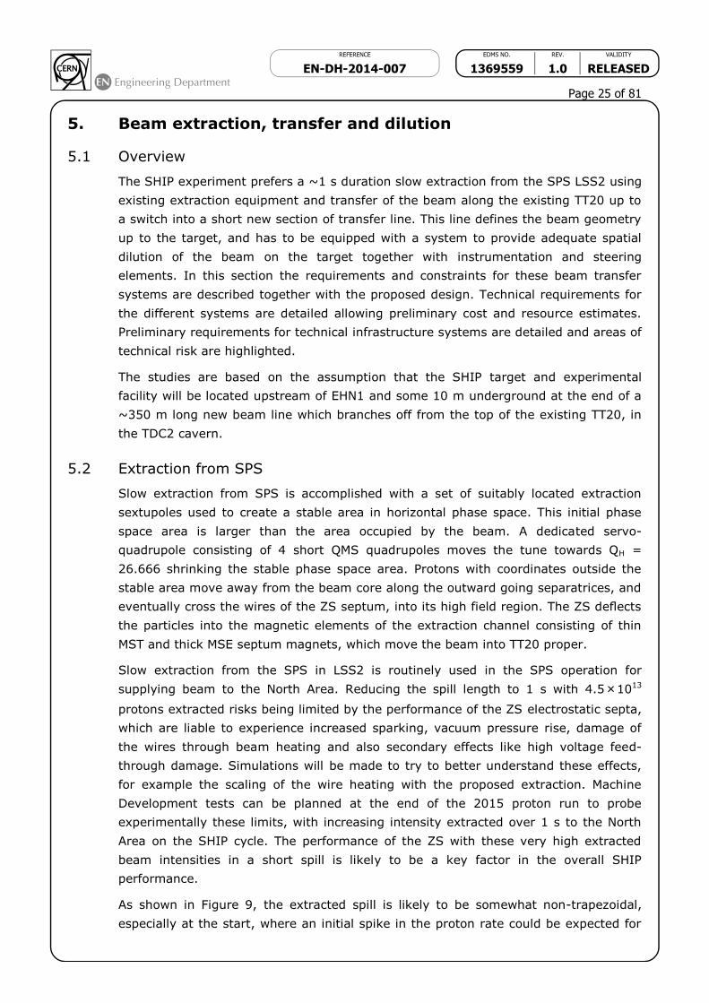
As shown in Figure 9, the extracted spill is likely to be somewhat non-trapezoidal,
especially at the start, where an initial spike in the proton rate could be expected for
REFERENCE EDMS NO. REV. VALIDITY
EN-DH-2014-007 1369559 1.0 RELEASED
Page 26 of 81
this short extraction time. This can have some impact on the energy deposition in the
target and could conceivably be mitigated by modifying the start of the sweep.
Figure 9: Well-regulated quasi-trapezoidal spill for SPS extraction (4.8 s
spill).
To avoid activation of the internal SPS dump TIDVG, it would be preferable to extract
all protons to the SHIP target, unlike the present beams to the North Area where a
few percent are routinely dumped to preserve the spill quality. This 100% extraction
can be accomplished but at the expense of the spill quality, and might be
accompanied by a spike in the proton rate or different spill lengths depending on the
total beam intensity – this is a topic which can be tested in a Machine Development.
The activation of the extraction region and of the aperture limits in the ZS will
increase in proportion to the total number of protons extracted per year - with the
SHIP extraction in addition to a North Area requirement assumed to be similar to
recent past years, an increase of a factor of maybe 3 to 6 or even more in the
radiation dose (a factor 2.6 compared to record year 2007) and equipment activation
and degradation (e.g. of cables) can be expected. More detailed estimates can be
made on the basis of the expected extraction duty cycle and yearly load, together with
the data from past years’ operation. Ways to reduce the beam losses should be
investigated, for instance improved instrumentation in the extraction regions.
5.3 Transport along TT20
The SHIP target location allows the re-use of about 600 m of the present TT20
transfer line, which has sufficient aperture for the slow-extracted beam at 400 GeV/c.
The powering scheme for the line remains basically unchanged up to the switch
element, but re-matching of the final section of the line will be needed to allow the
beam to pass with very low losses through the switch aperture – one potential issue to
check is whether the line optics can be changed on a cycle-to-cycle basis within a
super-cycle, at least for the quadrupole elements concerned. Interlocking of these
magnet currents would also need to be provided on a cycle-to-cycle basis – this is not
a conceptual problem.
The existing instrumentation is designed for slow extracted beams, and functionally
should be adequate. The question of whether the systems need consolidating or
extending due to the higher beam power remains to be investigated.

REFERENCE EDMS NO. REV. VALIDITY
EN-DH-2014-007 1369559 1.0 RELEASED
Page 27 of 81
5.4 Switching from TT20
One of the main challenges of the North Area location of the SHIP experiment is the
400 GeV/c switch out of TT20 to the new beam line, due to the high beam rigidity and
absence of space in the present beam line. An elegant suggestion is to replace the
three existing MSSB2117 splitter magnets with newly built splitters, which allow
negative polarity powering. This would provide an elegant way of doing this without
sacrificing the full slow spill to one of the existing North Area beam lines. With a two-
polarity splitter magnet, an extra beam line is possible, symmetric to the T6 beam line
but to the left of the T2 line instead of to the right, see Figure 10.
Figure 10: Schematic of start of new SHIP beamline, symmetric to T6 but to
the left of the T2/T4 line, with polarity-reversed MSSB2117 splitter acting as
a switch magnet.
The three existing MSSB magnets 211713, 211723 and 211732 need to be replaced
by similar magnets which allow enough aperture for the beam deflected in the
opposite direction. The main requirements for the new magnets are:
Replicate existing splitter functionality for present NA beams;
Polarity reversal possible within about 2 seconds;
Adequate good-field region around both sides of field-free septum hole;
Same ∫B.dl and physical length as present MSSB.
The present MSSB design [24] is an in-vacuum Lambertson septum, with a clever
vacuum separation to keep the coils and water connections in air, built with radiation
robust materials and low-maintenance assembly. The magnets operate with 0.8 T in
the gap, and have a limit Bmax of 1.6 T in the steel at the point of the septum element.
Interestingly, for the NA splitter design, the wedge angle of the septum is 36°, and
since Bmax.sin ≈ Bgap, it is therefore possible by running at higher current to increase
the gap field to about 0.95 T without a major effect on the field quality – the
REFERENCE EDMS NO. REV. VALIDITY
EN-DH-2014-007 1369559 1.0 RELEASED
Page 28 of 81
alternative of using a higher saturation steel like FeCo would gain something, but
would be much more expensive, mechanically tricky and lead to activation issues.
The gap is 75 mm high, which requires about 48 kA.turns at 0.8 T. The present coil
scheme of 48 turns and 1 kA can be retained. The coil technology is special, using
compacted MgO powder around a central copper current carrying water-cooled tube,
mechanically supported by an external grounded copper sheath. The MgO is
evacuated to avoid moisture degradation – the maximum voltage to earth is 1 kV.
The present MSSB are built with solid yokes, assembled from several precision
machined pieces. Because of the need to switch the polarity between SHIP and normal
FT cycles a laminated yoke is essential. A possible technology would be 1.5 mm
punched laminations, blue-steamed for insulation and assembled with a stacking
factor of ~98%. This technology is routinely used in the SPS for the extraction septa
MSE/T that are also exposed to high radiation doses. The drive current (or the
magnetic length, in case the power convertors are really limited to 1000 A) might
need to be increased by 2% compared to the existing magnet to compensate for slight
reduction in ∫B.dl.
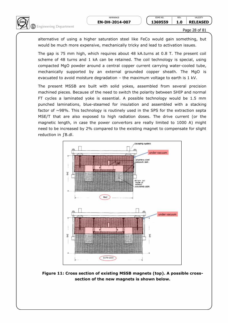
Figure 11: Cross section of existing MSSB magnets (top). A possible cross-
section of the new magnets is shown below.

REFERENCE EDMS NO. REV. VALIDITY
EN-DH-2014-007 1369559 1.0 RELEASED
Page 29 of 81
The new magnet cross-section can be a simple variation of the present MSSB,
Figure 11, with the good field region extended to the other side of the septum hole.
Here some advantage can be taken of the operation at 400 GeV/c – the maximum
offset for the switched beam at the exit of the 3rd MSSB is around 90 mm. Allowing
another 40 mm for the beam size and orbit, alignment tolerances, the good field
region (and pole width) needs to be extended by 130 mm only, although an extra 150
mm would make the septum hole symmetric to the pole. The overall yoke width is
likely to increase from 1042 mm to approximately 1170 mm, and the weight will
increase from the present 24 tonnes to about 27 tonnes. Main parameters are
compared to the existing MSSB in Table 11. The inductance and resistance are scaled
from the existing magnet, with the preliminary pole width and coil size.
The main parameters of the new MSSB-S magnet are also given below in Table 11.
Parameter MSSB New MSSB-S
Magnetic length [m] 4.7 4.7
Gap field [T] 0.8 0.8
Stacking factor [%] 100 98
Coil turns 48 48
Current [A] 994 1014
Vertical gap [mm] 75 75
Pole width [mm] 400 530
Magnet inductance [H] 0.11 0.14
Coil resistance [m] 65 66
Number of magnets in series 3 3
Minimum rise-time [s] 10 (tbc) 2
Maximum voltage to ground (3 magnets in series) [V] ~250 400
Table 11: Parameters of the existing and new (preliminary) MSSB magnet.
5.5 New beam line to target
A maximum deflection angle to exit the TDC2 tunnel is beneficial to reduce the
longitudinal extent of the civil engineering works in the crucial junction region. Large
bends of type MBB or MBN will be needed, which can run at almost 2 T and are 6.2 m
or 5.0 m long, respectively. It must be noted that the MBN magnets are highly
inductive, so pulsing rapidly a large series of magnets would require a converter with
an unrealistically large voltage rating.
Overall, an angle of at least 80-100 mrad is needed with respect to TT20. In the first
optics checks this was obtained with the 8 mrad from the three MSSB switch magnets,
plus 9x MBB magnets running at a conservative field of 1.73 T giving 8 mrad each. A
total of about 11 MBN magnets would be needed to reach the same deflection.
In the initial configuration studied, the MBBs are grouped into a single dipole as early
as possible, and two ‘standard’ half-cells of 4 dipoles each. It is to be noted that no

REFERENCE EDMS NO. REV. VALIDITY
EN-DH-2014-007 1369559 1.0 RELEASED
Page 30 of 81
new dipoles are located near the second splitter, for reasons of installation,
maintenance and radiation dose during operation.
The first version of the configuration is shown in Figure 12, below. New dipoles (MBB)
and new quadrupoles (approximate locations) are indicated.
Figure 12: A first switch and branch-off layout for the new SHIP beam line
based on modified MSSB and new MBB magnets. Dilution magnets are not
shown.
The transverse optics has not been studied in detail but is not expected to pose
problems – the main issue is just the acceptance for the beam, since anyway a large
blow-up of the transverse beam size is needed at the target. It is assumed that about
5 new quadrupoles, of type QNL will be needed, with one new QSL slim quadrupole as
the first magnetic element after the splitter/switch in the new beam line. A maximum
of 6 corrector dipoles can also be assumed, which can be 50 A MDX-type.
The numbers and types of magnets needed for the beam line are given in Table 12, in
addition to the number of converters and the required current/voltage.
Function Magnet type Max I [A] Max V (V) # magnets # convertors
Switch MSSB-S 1000 500 3 1
Main bends MBN (MBB) 1500 (6000) ? 12 (10) 1
Main quads QNL 400 ? 5 5
Main quad (slim) QSL 400 ? 1 1
Corrector dipoles MDX 50 ? 6 6
Sweep dipole MPLH? 400 ? 2 2
Table 12. Number and types of magnets for new beam line, with power converter
numbers and ratings.
5.6 Beam dilution on the target
The maximum beam energy density on the target is an issue for the target design.
With a 1 s long extraction spill, a pair of orthogonal conventional magnets with a fast
Lissajous powering function could be foreseen to maximise the length of the sweep on
the target block. With a drift of at least 150 m available before the target and a sweep
radius tentatively fixed at 30 mm, a maximum deflection of only 0.2 mrad per plane is

REFERENCE EDMS NO. REV. VALIDITY
EN-DH-2014-007 1369559 1.0 RELEASED
Page 31 of 81
needed. Possible magnet types could be MPLH (SPS extraction bumpers) that can
ramp with a dI/dt of around 1’300 A/s. With a current of ~65 A corresponding to 0.2
mrad, a maximum sweep frequency of about 3 Hz would be possible using the present
type of magnet and power converter.
A full optimisation of the sweep is required taking into account the possible magnet
and powering characteristics, as well as the limitations of the target in terms of
protons per mm2. Some idealised sweep forms have been proposed for evaluation, for
example an idealised Archimedean spiral (Figure 13) with a transverse spacing
between turns of about 6 mm (1 sigma), 5 turns total in 1000 ms, a starting radius of
5 mm, a finishing radius of 35 mm and a constant sweep speed in mm/ms. This would
imply a varying frequency of the sine/cosine waveforms, as also shown in Figure 13.
For this example the product of the frequency and kick is constant and corresponds to
0.2 mrad at 3 Hz, which is within reach of the existing MPLH magnet. Starting with
larger amplitude and spiraling inwards would probably be easier for the dilution
magnet powering.
Figure 13: An idealised sweep shape (left) optimised for uniform proton
density on the target. The corresponding powering functions in kick are also
shown (right).
5.7 Magnet powering
The existing TT20 main bend MBE and MBB magnets are powered in series and no
changes are foreseen. For the powering of the new MSSB magnets, a variant of the
Linac4 transfer line converters (APOLLO family) can be used. These can be assembled
in 4 modules to deliver the requested current/voltage, in order to allow all three
magnets to be powered in series. If needed, the maximum voltage of around 400 V
could be reduced by a factor of two with balancing the voltage in +/-, however this
does not seem necessary to foresee at this stage as 400 V is well within the voltage
limit of the MgO coil conductor.
The new main bend magnets (MBB, MBN) powering will likely need a new 6’000 A
convertors similar to that used for main SPS magnets. One cost reducing option to

REFERENCE EDMS NO. REV. VALIDITY
EN-DH-2014-007 1369559 1.0 RELEASED
Page 32 of 81
investigate would be the feasibility of powering the new magnets in series with the
existing string of MBB/MBE dipoles for TT20 using the same main convertor, with a
suitable small trim convertor as done for the separate TT20 dipole families. This
would, however, probably impose using MBBs or new MBB-compatible magnets for the
bends.
For the new quadrupoles, likely to be 5-6 in number of type QNL, the 400 A and the
200 V converters will be similar in specification to those for the existing TT20
individual quadrupole converters. The first slim quadrupole will be of type QSL, for
integration reasons, which uses the same converter.
The power converter location needs to be defined – BA80 contains all of the existing
convertors for the TDC2/TCC2 region and the beam lines to the NA targets, but is
completely full. Suitable space in any new auxiliary building needs to be reserved, of
the order of 200 m2 in addition to provision for any new transformers.
5.8 Summary
The main technical challenges are the design and construction of a new splitter/switch
magnet, which is likely to require a longer lead-time than a ‘normal’ design of warm
magnet, and the achievable performance of the ZS septum with the high extracted
beam intensity, linked to the activation of the extraction region. The design of the
dilution system will require some care in the magnet and powering choice, but the
difficulty is reduced by the small kick strengths needed.
Overall, and despite these interesting challenges, the beam transfer aspects appear
feasible.
6. SHIP Target and Target Station Design
6.1 Introduction
The SHIP proposal requires the realization of a production target that has the twofold
objective of producing the charmed mesons required by the physics program as well
as to dump the SPS primary beam. Given the involved beam power, the experimental
requirements are challenging, as a high-Z material with a short interaction length is
needed in order to increase as much as possible the reabsorption of pions and kaons
produced in the spallation process that would otherwise generate a background for the
experiment. Hence the energy deposition is extremely dense, leading to high
temperature and high levels of stress/strain in the material itself. A preliminary
investigation on the feasibility of such a device has been conducted on a tungsten
target, with a total length of at least 50 cm, corresponding to about 5.5at 400 GeV.
A hadron absorber encloses the production target, with the double objective of
absorbing the remaining hadrons emerging from the target and the non-colliding
protons and to significantly reduce the radiation exposure of the muon filter which
separates the target bunker from the experimental hall.

REFERENCE EDMS NO. REV. VALIDITY
EN-DH-2014-007 1369559 1.0 RELEASED
Page 33 of 81
The production target is part of a target station which includes all services associated
to its cooling, operation & control, manipulation, handling and storage. The shielding
configuration as well as the air activation are taken into account already at this stage
of the design since they will have a strong impact on feasibility and cost of the facility.
6.2 Target design
The production target is one of the most challenging aspects of the proposed
installation, due to the very high energy and power density that will be reached during
operation. In terms of beam power delivered on target, the installation will be in a
similar operational regime as of the Spallation Neutron Source at ORNL (US) or to the
Material Life Sciences spallation sources at JPARC (Japan).
For the analysis described in this section, the beam parameters presented in Table 13
have been taken into account:
Baseline Ultimate
Beam protons protons
Momentum [GeV/c] 400 400
Beam Intensity [1013 p/cycle] 4.5 7.0
Cycle length [s] 7.2 8.4
Spill duration [s] 1.0 2.2
Expected r.m.s. spot size (H/V) [mm] 6/6 6/6
Average beam power on target [kW] 400 530
Average beam power on target during spill [kW] 2900 2030
Table 13: SPS beam parameters considered for the preliminary assessment of the target design.
It is important to note that given the SPS beam characteristics for the SHIP
experiment (i.e. shorter spill duration in the “Baseline” case with respect to the
“Ultimate”) the average beam power on the target during the spill is roughly 40%
higher for the Baseline configuration rather than for the Ultimate.
FLUKA Monte Carlo simulations have been performed to assess the total energy
deposition and energy density produced by the interaction of the primary proton
beam. For this preliminary assessment, a bare W rod – with a density of 19.3 g/cm3 –
of 50 cm length and 20 cm diameter has been taken into account. The beam footprint
has been conservatively assumed as constituted by a uniform circular sweep of 3 cm
radius with a sigma of 6 mm.
Simulations show that – for the current target geometry – roughly 81% of the energy
is deposited inside the target, corresponding to a super-cycle-average power of 324
kW for the baseline scenario and 430 kW for the ultimate one. The maximum energy
densities that are reached are in the order of 3.5 kJ/cm3/pulse for the baseline beam
and 5.5 kJ/cm3/pulse for the ultimate one. See Figure 14 for the energy distribution.

REFERENCE EDMS NO. REV. VALIDITY
EN-DH-2014-007 1369559 1.0 RELEASED
Page 34 of 81
The target must be actively cooled: light (or heavy) water and helium gas cooling are
used in other laboratories and shall be studied in the framework of a technical design
report. For this preliminary assessment active (light) water cooling has been
considered.
In order to assess the feasibility of the proposed target, thermo-mechanical and
computational fluid dynamical analyses have been performed, using the FLUKA-
generated energy deposition map as heat source in conjunction with the parameters
associated to the two scenarios of Table 13.
Figure 14: The figure shows a transversal cut of energy density induced by
the 400 GeV/c primary beam on a bare W target with a 3 cm radius circular
sweep. The average is made ±2 cm around the position of the peak energy
density.
Three targets configurations have been studied:
1. Full solid W target, 50 cm long and 20 cm diameter.
2. Sliced W target, 20 cm diameter each, 10 cm length (5 discs).
3. Sliced W target, plates of 20x20 cm2 each, with a longitudinal configuration of
4 plates of 5 cm each, 2 plates of 10 cm each and one last of 20 cm.
For configuration #1, only tangential water cooling has been considered, while for
configuration #2 and #3, an additional cooling interface between the various faces has
been considered to increase the surface of heat transfer. For all configurations, two
water cooling regimes have been taken into account, i.e. 5 m/s and 10 m/s, assuming
water at 25 °C and at atmospheric pressure. A CFD calculation has been employed to
evaluate the correct heat transfer coefficient from the material surface to the water
(assuming 1 cm gap between the target discs).
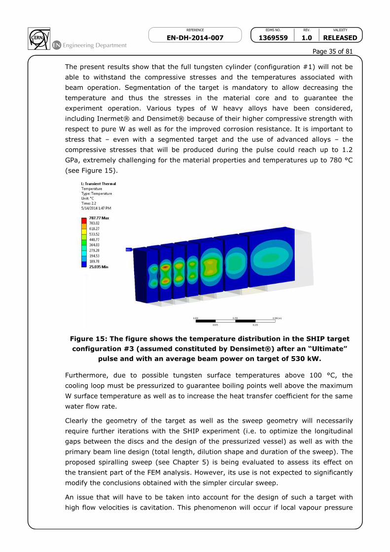
REFERENCE EDMS NO. REV. VALIDITY
EN-DH-2014-007 1369559 1.0 RELEASED
Page 35 of 81
The present results show that the full tungsten cylinder (configuration #1) will not be
able to withstand the compressive stresses and the temperatures associated with
beam operation. Segmentation of the target is mandatory to allow decreasing the
temperature and thus the stresses in the material core and to guarantee the
experiment operation. Various types of W heavy alloys have been considered,
including Inermet® and Densimet® because of their higher compressive strength with
respect to pure W as well as for the improved corrosion resistance. It is important to
stress that – even with a segmented target and the use of advanced alloys – the
compressive stresses that will be produced during the pulse could reach up to 1.2
GPa, extremely challenging for the material properties and temperatures up to 780 °C
(see Figure 15).
Figure 15: The figure shows the temperature distribution in the SHIP target
configuration #3 (assumed constituted by Densimet®) after an “Ultimate”
pulse and with an average beam power on target of 530 kW.
Furthermore, due to possible tungsten surface temperatures above 100 °C, the
cooling loop must be pressurized to guarantee boiling points well above the maximum
W surface temperature as well as to increase the heat transfer coefficient for the same
water flow rate.
Clearly the geometry of the target as well as the sweep geometry will necessarily
require further iterations with the SHIP experiment (i.e. to optimize the longitudinal
gaps between the discs and the design of the pressurized vessel) as well as with the
primary beam line design (total length, dilution shape and duration of the sweep). The
proposed spiralling sweep (see Chapter 5) is being evaluated to assess its effect on
the transient part of the FEM analysis. However, its use is not expected to significantly
modify the conclusions obtained with the simpler circular sweep.
An issue that will have to be taken into account for the design of such a target with
high flow velocities is cavitation. This phenomenon will occur if local vapour pressure

REFERENCE EDMS NO. REV. VALIDITY
EN-DH-2014-007 1369559 1.0 RELEASED
Page 36 of 81
is greater than local pressure, generating cavities or bubbles; as the cavities will leave
the low pressure region they will collapse, potentially damaging the target vessel wall.
One solution to reduce this effect is to avoid drastic bends (to reduce sudden pressure
drops) as well as to increase circuit pressure, in order to guarantee that the pressure
in all regions will be above the local vapour pressure. Increasing the water pressure
will have the additional benefit of increasing the boiling point of water (as an example,
water at 5 bar has a boiling point at 150 °C).
The present study did not take into consideration erosion/corrosion processes due to
water flow nor the degradation of mechanical properties from radiation damage. The
results show already that the projected operational conditions are not far from the
limits of pure tungsten therefore a vigorous R&D program on materials (use of
tungsten heavy or doped alloys, eventual claddings, etc.) and target configuration is
certainly necessary to confirm the feasibility of the project. Some iteration with the
SHIP experiments and on the extraction scheme from the SPS, as well as on the
layout of the transfer line to eventually modify the size of the beam and of the dilution
path might also have to be considered to find a good balance between physics output
and cost.
6.3 Target station design
The SHIP target station design could profit from the work performed in the framework
of the CERN Neutrino Facility (CENF) target facility. The design is adapted for shallow
target installations, and is based on a multi-compartment solution in which volumes
are well subdivided (from a ventilation point of view) and are constituted by
underground areas accessible from a surface target hall (see Figure 16 for more
information).
Figure 16: Isometric view of the proposed CENF target station hall.

REFERENCE EDMS NO. REV. VALIDITY
EN-DH-2014-007 1369559 1.0 RELEASED
Page 37 of 81
Taking into account the on-going discussions with GS/SE, the SHIP target hall will be
designed as a surface or semi-underground building roughly 38 meters long, 20
meters wide and 14.5 meters high. The target building includes also the first part of
the muon filter tunnel, which will be accessible from the target hall itself.
The spallation target is located on the bottom of a shielded bunker, assumed to be
roughly 10 meters long and 8.5 meters wide, for a total depth of about 12 meters with
respect to the surface of the target hall (See Figure 17). A massive (~3.5 kton) iron
shielding (i.e. hadron absorber) surrounds the spallation target in order to reduce the
prompt dose rate during operation and the residual dose rate of the target during
shutdown: according to preliminary RP evaluations, roughly 400 cm is needed above
the target, 500 cm downstream (before the muon plug) and 320 cm below and
laterally (on each side). In order to minimize the radiation issues in the primary beam
line, the beam opening must be kept as small as possible, but still of the same order
of magnitude as the target diameter (20 cm). A TAN-like system could be conceived to
reduce the activation of the primary tunnel equipment due to neutral (essentially
neutrons) particles travelling backwards from the target on the primary beam pipe.
Figure 17: Preliminary view of the SHIP target station, with the proposed
configuration of the target hall and of the target bunker.

REFERENCE EDMS NO. REV. VALIDITY
EN-DH-2014-007 1369559 1.0 RELEASED
Page 38 of 81
Due to the very high residual dose rate of the target (and of the annex iron shielding),
remote manipulation and handling is mandatory. In case of target failure (which must
be foreseen as an operational possibly), an annex area of the target bunker (“cask
storage”) is foreseen to temporarily store the target for cooling down. The target hall
must be equipped with a 40 ton – fully redundant – crane to allow the handling of the
iron shielding blocks. Redundancy will be important in case of failure of any
mechanical system (i.e. the gearbox) during target handling.
Similarly to what has been envisaged for the CENF target area, the target bunker and
the target storage zone are embedded inside a helium-filled vessel atmosphere (see
Figure 18), with online circulation and purification. This solution has two major
advantages over an air filled solution:
1. Reduction of the air activation. This simplifies interventions in case of target
failures that require opening of the internal shielding and reduces the
environmental impact of the installation.
2. Reduction of the risks of radiation-accelerated corrosion of the target
pressurized vessel (and associated equipment) and of the iron shielding.
A ~100 cm thick concrete wall separates the edge of the helium vessel from the
primary beam line upstream, see Figure 18.
A buffer area – also called service pit – is foreseen on the top of the helium vessel, in
order to permit human interventions on the various feed-throughs (water, helium,
control signals) between the service areas and the internal part of the helium
vessel/target bunker. An extra 160 cm concrete layer will additionally shield the
service pit from the target hall. The latter will be removable to allow crane access to
the target bunker.
The SHIP target station ventilation system will be designed respecting the
ISO17874:2004 norms, with a pressure cascade between the various compartments,
from -60 Pa of the target hall to -220 Pa of the most exposed zones. A recirculation
system for the most radioactive areas (helium vessel and service pit) should be
foreseen to allow the decay of short-lived isotopes before release into the
environment. The air-tightness of the various areas will be a central part of the target
station design and will be interlocked with beam operation.
The cooling and ventilation equipment required for the functioning of the installation
(target cooling, hadron absorber/shielding cooling and helium circulation) will be
located in an underground area (tentatively 1500 cm long and 750 cm wide, for a total
depth of 8-10 meters) – constituted by two/three underground levels – connected to
the target bunker via the service pit (see Figure 18). Access from the target hall will
be possible by means of a dedicated stairwell.
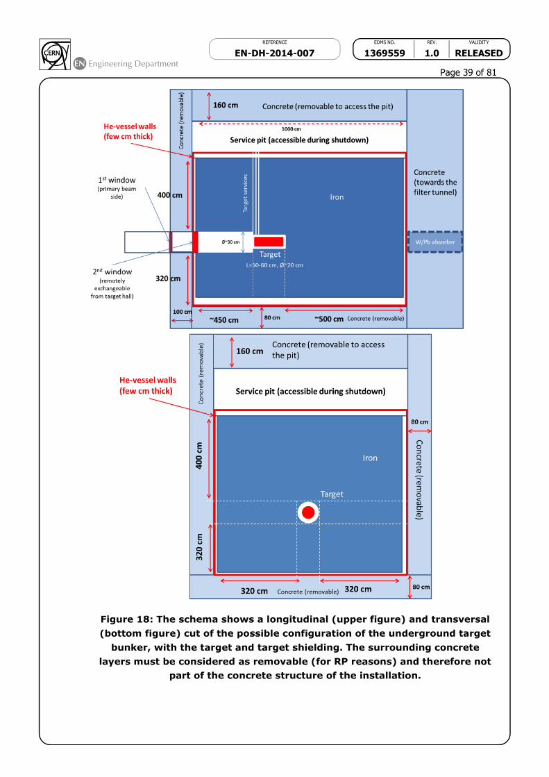
REFERENCE EDMS NO. REV. VALIDITY
EN-DH-2014-007 1369559 1.0 RELEASED
Page 39 of 81
Figure 18: The schema shows a longitudinal (upper figure) and transversal
(bottom figure) cut of the possible configuration of the underground target
bunker, with the target and target shielding. The surrounding concrete
layers must be considered as removable (for RP reasons) and therefore not
part of the concrete structure of the installation.
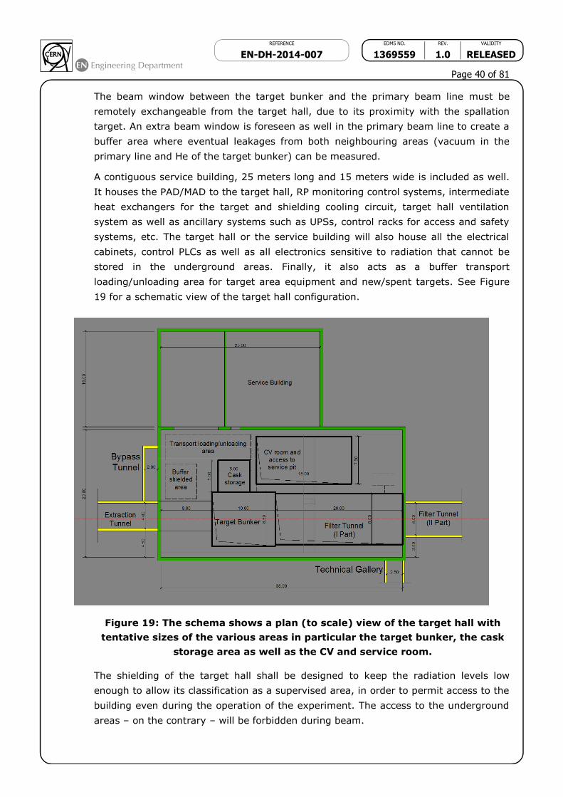
REFERENCE EDMS NO. REV. VALIDITY
EN-DH-2014-007 1369559 1.0 RELEASED
Page 40 of 81
The beam window between the target bunker and the primary beam line must be
remotely exchangeable from the target hall, due to its proximity with the spallation
target. An extra beam window is foreseen as well in the primary beam line to create a
buffer area where eventual leakages from both neighbouring areas (vacuum in the
primary line and He of the target bunker) can be measured.
A contiguous service building, 25 meters long and 15 meters wide is included as well.
It houses the PAD/MAD to the target hall, RP monitoring control systems, intermediate
heat exchangers for the target and shielding cooling circuit, target hall ventilation
system as well as ancillary systems such as UPSs, control racks for access and safety
systems, etc. The target hall or the service building will also house all the electrical
cabinets, control PLCs as well as all electronics sensitive to radiation that cannot be
stored in the underground areas. Finally, it also acts as a buffer transport
loading/unloading area for target area equipment and new/spent targets. See Figure
19 for a schematic view of the target hall configuration.
Figure 19: The schema shows a plan (to scale) view of the target hall with
tentative sizes of the various areas in particular the target bunker, the cask
storage area as well as the CV and service room.
The shielding of the target hall shall be designed to keep the radiation levels low
enough to allow its classification as a supervised area, in order to permit access to the
building even during the operation of the experiment. The access to the underground
areas – on the contrary – will be forbidden during beam.

REFERENCE EDMS NO. REV. VALIDITY
EN-DH-2014-007 1369559 1.0 RELEASED
Page 41 of 81
7. Civil Engineering for the SHIP experiment
7.1 Overview
Civil Engineering costs for projects such as SHIP typically represent approximately one
third of the overall budget. For this reason, particular emphasis has been placed on
Civil Engineering (CE) studies, to ensure a cost efficient conceptual design. This
chapter provides an overview of the designs adopted for the civil engineering.
The CE studies were based on the assumption that the SHIP facility will be sited on
the CERN Prevessin laboratory in France. A new machine extraction tunnel will be
required in the North Area, leading to a new Target and Experimental facility. All civil
engineering works for the project are fully located within existing CERN land on the
Prevessin campus.
Figure 20 is a schematic layout of the civil engineering complex for the SHIP project.
Figure 20: Schematic layout of the civil engineering complex.
The key features of this layout are:
85m long Junction Cavern in the TDC2 line
170m long machine Extraction Tunnel (4m wide by 4m high similar to TDC2)
15m long by 15m wide Access building including a shaft to reach the Extraction
Tunnel line

REFERENCE EDMS NO. REV. VALIDITY
EN-DH-2014-007 1369559 1.0 RELEASED
Page 42 of 81
38m long by 20m wide Target Area
25m long by 15m wide Service building directly connected on one side to the
Target Area
140m long Technical Gallery (2.5m wide by 2.5m high similar to GT801)
70m long Filter tunnel downstream Target Bunker
120m long by 20m wide Detector Hall
40m long by 20m wide Access building on top of the Detector Hall
All underground works are to be excavated using the “cut-and-cover” method.
The civil engineering studies presented in this chapter have been performed by the
GS-SE Group with various technical experts within the SHIP team. External
consultancy firms have also contributed in some areas of these designs.
7.2 Civil Engineering
This section describes the civil engineering envisaged both on surface and
underground for the SHIP Project.
7.2.1 Location
The proposed siting for the SHIP Project is fully located within existing CERN land on
the Prevessin campus. The on-surface alignment of the complex consists of green
areas and woodland.
This location is extremely well suited to housing the SHIP project, with the very stable
and well understood ground conditions. Detailed geological records exist and have
been utilised for this study to minimise the costs and risk to the project. The
underground works will be constructed in the stable Moraine glacial deposits at a
depth of approximately 10 m in an area with little seismic activity.
The governments of France and Switzerland have long standing agreements
concerning the support of particle accelerators in the CERN region, which make it very
likely that the necessary planning permissions could be granted in a relatively short
timeframe.
7.2.2 Land Features
The proposed location for the project is situated within the Swiss midlands embedded
between the high mountain chains of the Alps and the lower mountain chain of the
Jura. CERN is situated at the feet of the Jura mountain chain in a plain slightly inclined
towards the lake of Geneva. The surface terrain was shaped by the Rhone glacier
which once extended from the Alps to the valley of the Rhone. The water of the area
flows to the Mediterranean Sea. The absolute altitude of the surface ranges from 430
to 500 m with respect to sea level.
7.2.3 Geology
The proposed path of SHIP is situated within the Geneva Basin, a sub-basin of the
large North Alpine Foreland (or Molasse) Basin. This is a large basin which extends

REFERENCE EDMS NO. REV. VALIDITY
EN-DH-2014-007 1369559 1.0 RELEASED
Page 43 of 81
along the entire Alpine Front from South-Eastern France to Bavaria, and is infilled by
clastic “Molasse” deposits of Oligocene and Miocene age. The basin is underlain by
crystalline basement rocks and formations of Triassic, Jurassic and Cretaceous age.
The Molasse, comprising an alternating sequence of marls and sandstones (and
formations of intermediate compositions) is overlain by Quatemary glacial moraines
related to the Wurmien and Rissien glaciations.
Figure 21 shows a typical geological borehole log for the Moraines in the SHIP area.
Figure 21: Typical geological borehole log and long profile for the area.

REFERENCE EDMS NO. REV. VALIDITY
EN-DH-2014-007 1369559 1.0 RELEASED
Page 44 of 81
7.2.4 Site Development
As the SHIP Project is located on the CERN site at Prevessin, it is assumed that the
existing facilities such as office space, restaurant, main access, road network etc are
sufficient and have not been costed. However, some additional site development will
need to be included in the cost estimate:
New access road and car park
Drainage networks
Landscaping and planting
Spoil dumps
All temporary facilities needed for the construction works will also have to be included
in the cost estimate.
7.2.5 Construction Methods
It is envisaged that all underground works will be executed using “open-cut’ rather
than tunnelling methods. The TDC2 tunnel itself was excavated in 1972 using the “cut
and cover” technique.
Figure 22 shows the start of the tunnelling for the TT20 line going down towards the
SPS.
Figure 22: Photo from May1972 showing the start of tunnelling for TT20 line
going down to SPS.

REFERENCE EDMS NO. REV. VALIDITY
EN-DH-2014-007 1369559 1.0 RELEASED
Page 45 of 81
The new civil engineering works will be downstream of the TT20/TDC2 area, so it is
envisaged that all the excavation works will either be entirely open cut, or with the aid
of retaining walls, as shown in Figure 23.
Figure 23: Proposed excavation methods for SHIP
7.2.6 TDC2 Junction Cavern
The junction cavern consists of an 85 m long new facility in the existing TDC2
complex, providing the starting point for the new extraction tunnel as shown in
Figure 24. This will mean that an approximately 100 m length of existing machine and
services will have to be removed to allow demolition works to be executed. The
potential risk of the existing concrete and surrounding earth being radioactively
contaminated still needs to be assessed. This could potentially have a significant
impact on the cost of the SHIP project.
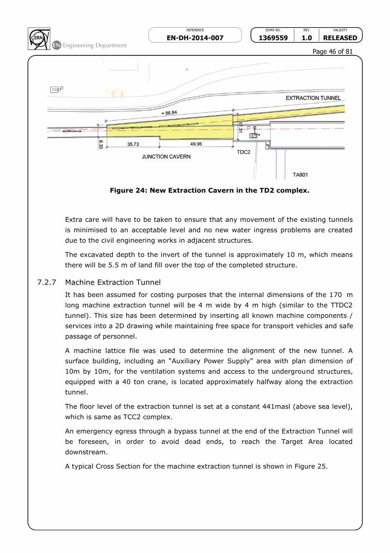
REFERENCE EDMS NO. REV. VALIDITY
EN-DH-2014-007 1369559 1.0 RELEASED
Page 46 of 81
Figure 24: New Extraction Cavern in the TD2 complex.
Extra care will have to be taken to ensure that any movement of the existing tunnels
is minimised to an acceptable level and no new water ingress problems are created
due to the civil engineering works in adjacent structures.
The excavated depth to the invert of the tunnel is approximately 10 m, which means
there will be 5.5 m of land fill over the top of the completed structure.
7.2.7 Machine Extraction Tunnel
It has been assumed for costing purposes that the internal dimensions of the 170 m
long machine extraction tunnel will be 4 m wide by 4 m high (similar to the TTDC2
tunnel). This size has been determined by inserting all known machine components /
services into a 2D drawing while maintaining free space for transport vehicles and safe
passage of personnel.
A machine lattice file was used to determine the alignment of the new tunnel. A
surface building, including an “Auxiliary Power Supply” area with plan dimension of
10m by 10m, for the ventilation systems and access to the underground structures,
equipped with a 40 ton crane, is located approximately halfway along the extraction
tunnel.
The floor level of the extraction tunnel is set at a constant 441masl (above sea level),
which is same as TCC2 complex.
An emergency egress through a bypass tunnel at the end of the Extraction Tunnel will
be foreseen, in order to avoid dead ends, to reach the Target Area located
downstream.
A typical Cross Section for the machine extraction tunnel is shown in Figure 25.
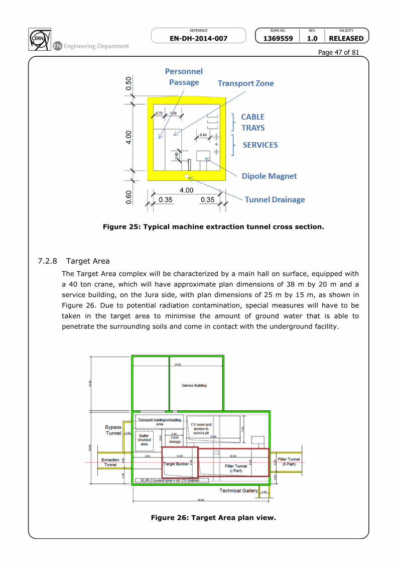
REFERENCE EDMS NO. REV. VALIDITY
EN-DH-2014-007 1369559 1.0 RELEASED
Page 47 of 81
Figure 25: Typical machine extraction tunnel cross section.
7.2.8 Target Area
The Target Area complex will be characterized by a main hall on surface, equipped with
a 40 ton crane, which will have approximate plan dimensions of 38 m by 20 m and a
service building, on the Jura side, with plan dimensions of 25 m by 15 m, as shown in
Figure 26. Due to potential radiation contamination, special measures will have to be
taken in the target area to minimise the amount of ground water that is able to
penetrate the surrounding soils and come in contact with the underground facility.
Figure 26: Target Area plan view.

REFERENCE EDMS NO. REV. VALIDITY
EN-DH-2014-007 1369559 1.0 RELEASED
Page 48 of 81
The spallation target would be located on the bottom of a shielded bunker, assumed to
be 10 m long and 8m wide, for a total depth of about 10m with respect to the surface
of the target hall. An annex area of the target bunker (“target storage”) with
approximate plan dimensions of 5m by 5m has to be foreseen in order to temporarily
store the target for cooling down.
The cooling and ventilation equipment required for the functioning of the installation
(target cooling, hadron absorber/shielding cooling and helium circulation) could be
located in an underground area (15m long and 7.5m wide, for a total depth of 8-10m)
connected to the target bunker via the service pit.
The final layout of the Target Hall is completed by a buffer area, a dedicated zone for all
the electrical cabinets, control PLCs as well as all electronics sensitive to radiation that
cannot be stored in the underground areas and finally a transport loading/unloading
area next to the trucks access.
The Target Area cross section is shown in Figure 27.
Figure 27: Target Area cross section.
7.2.9 Filter Tunnel
The Filter tunnel will be 70 m long with the invert level at 441 masl. The first part (20
m long) will be embedded beneath the target hall where a separate personnel access
will be provided. The equipment located in this area will be installed using the target
hall crane. The tunnel cross section will be 8 m wide by 5 m high.
The second part (50 m long) downstream the target area up to the detector building
will be 5 m wide by 5 m high, as indicated in Figure 28.

REFERENCE EDMS NO. REV. VALIDITY
EN-DH-2014-007 1369559 1.0 RELEASED
Page 49 of 81
Figure 28: Filter Tunnel Cross Section.
7.2.10 Detector Building
The Detector Building will be 120 m long by 20 m wide and equipped with a 40 ton
crane.
The floor level of the experiment is set at 437.93 masl. This level was calculated
taking into account the beam line level, which remain the same (442.18 masl) along
the entire SHIP complex, and the equipment volume (vacuum vessel + magnet)
around the beam line.
The detector hall will be almost fully underground. A surface building (30 m long) for
assembly and installation purposes will be positioned over the detector hall. This
building will be equipped with a 40 ton crane and have an opening, which can be
covered with precast concrete beams, providing a vertical access to the underground
area.
A cross section with the access building and the detector hall below is shown in
Figure 29.
Figure 29: Detector Building.

REFERENCE EDMS NO. REV. VALIDITY
EN-DH-2014-007 1369559 1.0 RELEASED
Page 50 of 81
7.2.11 Civil Engineering Cost Estimate for WP
The cost estimate for the SHIP Project is based on the layouts presented in this
chapter. The estimate includes all aspects of construction, final engineering designs
and construction management. Many of the rates used to formulate this estimate will
be based on real construction costs from LHC experience (1998-2005).
The total cost for each Work Package obtained taking into account the main works
activities related is shown in Chapter 9. The estimated accuracy is ±30%. Not included
in this estimate are:
GS-SE resources
Earthworks assume stockpiling on CERN site and no special treatment required
for radiation
Instrumentation for ground stability monitoring not included
Special foundation support for facilities (e.g. Detector, etc) not included
Shielding precast concrete blocks not included
Infrastructure systems not included (ventilation, electricity, etc)
7.2.12 Civil Engineering Scheduling and Resource Considerations.
A preliminary schedule has been studied for the construction of the SHIP Project using
the knowledge acquired from the construction of previous similar schemes at CERN.
This timeline is shown, along with the other activities in the SHIP project in Chapter 9.
Two years are needed for pre-construction activities (design studies, building permits,
tendering) after formal approval of the project. The CE works are split in three
packages. The first one includes the Extraction Tunnel and the Target Area works for a
period of 15 months scheduled before the LS2. Then during the LS2 period has been
scheduled to carry out the Junction Cavern (15 months), adding the demolition of the
existing TDC2 portion. The last package (18 months) is finally expected at the end of
LS2 for the Filter Tunnel and Detector works.
In order to cause minimal interference to the operation of the current fixed target
program in the North Area, maximum advantage must be taken from the LS2
shutdown (2018-2019) to construct the junction cavern and install the splitter and
proton line magnets.
8. Preliminary radiation protection considerations for SHIP
The high number of protons impinging on the SHIP target of 2×10²⁰ within 5 nominal
years combined with the proposed location of the SHIP experiment close to ground
level poses several challenges for radiation protection. Radiation protection guidelines
for the design of such a high powered facility are given in Appendix 1. The five most
important aspects to be studied initially for the SHIP facility from a radiological
viewpoint are:
● Prompt radiation: sufficient shielding is needed to reduce the levels of radiation in
areas accessible during beam operation to levels that allow the classification as

REFERENCE EDMS NO. REV. VALIDITY
EN-DH-2014-007 1369559 1.0 RELEASED
Page 51 of 81
Supervised Radiation Area or Non-Designated Area [26]. In particular the
production of high-energy muons (very difficult to shield) close to surface level
including pertinent shielding requirements has to be studied carefully.
● Residual radiation after beam stop: only remote handling is possible in and around
the target area. The design of the cooling circuits in the target requires detailed
studies as the liquids will become radioactive and any handling needs to be
optimised. In addition, disposal pathways for radioactive liquids need to be
identified.
● Air activation: the air volume in the target area has to be minimised in order to
reduce the production and releases of air-born radioactivity. The target bunker plus
shielding, including the storage zone should be housed inside a helium-filled vessel.
● Environmental impact due to possible activation of soil and ground water: the
hazard might be mitigated by using a CENF like design (shielding and geo-
membrane around the target station).
● Radiological accident and incident scenarios need to be studied, in particular the
dose to workers and members of the public.
It is worth mentioning that the design of the SHIP facility will strongly benefit from
studies performed for the CENF project where similar concerns exist.
Radiation losses at the extraction from the PS have been a limiting factor for CNGS
and they will also be high for SHIP, but some improvements have been made during
LS1. An additional and important radiation protection aspect of the SHIP facility is the
beam losses in the SPS accelerator and extraction area towards SHIP. Estimated beam
losses during future SPS operation with up to 7×10¹³ protons per extraction are about
a factor of 7 higher than for CNGS beams1. Such high beam loss levels would result in
unacceptable residual dose rate and air activation levels in the SPS, having a strong
impact on the accessibility of the SPS and on the dose given to the public via airborne
radioactivity releases. In case these losses occur in unshielded locations the lifetime of
cables installed nearby will be reduced significantly. Similar issues might exist at the
PS as well. In order to prevent such high losses, future beam intensities shall be
limited to CNGS-like beam intensities or other means have to be found to reduce
beam losses at higher intensities.
Already at nominal beam intensity the dose levels will be a factor 3-6 higher than in
previous years. Without mitigation, this could lead to dose levels of 12 mSv/hr after a
month of cool-down. This needs careful study.
8.1 Radiation levels in TDC2
The beam extraction point for SHIP is presently foreseen at one of the most
radioactive areas in TDC2, namely, at the first splitter magnets. Therefore, personnel
will be exposed to high dose rate levels at work places during
removal/installation/modification of beam line elements. A careful planning of these
1 Quotation from collimator LIU review minutes

REFERENCE EDMS NO. REV. VALIDITY
EN-DH-2014-007 1369559 1.0 RELEASED
Page 52 of 81
activities combined with an optimized work and dose planning will be essential. A
detailed RP survey has been performed in October 2013 (after 10 months of cooling
time) in TDC2 and TCC2 to allow a thorough work and dose planning for cable
exchange activities in those areas in 2013/2014. The results of these surveys can be
found in EDMS [27]. For illustration, the ambient dose equivalent rates at the first
splitter magnet location are shown in Figure 30 below.
Figure 30: Ambient dose equivalent rates measured (in Sv/h) at the first
splitter magnets in October 2013. Values in orange are measured at contact
to the objects, in yellow at a distance of 40 cm.
Extraction of the SHIP beam line from TDC2 requires partial demolishing of the
existing tunnel structure of TDC2. The concrete wall of TDC2 and the soil close to
TDC2 tunnels are activated. In order to quantify the amount of activation as well as
the lateral distribution (volume) of activated soil it is advised to take soil samples
close to the TDC2 area.
Removal of existing beam line components has to be foreseen before civil engineering
work in TDC2 can start. Furthermore, the CE contractor needs to be authorised by his
national authority to send workers in radiation areas of a third party (for more
information see “Working on CERN site” [28]). The CE workers need to be classified as
Radiation Worker, have to receive all required safety trainings and need to be
individually monitored.
Although it is not directly related to SHIP, RP strongly advises studying the possibility
to add shielding around existing high beam loss points in TDC2. This will significantly
reduce the activation of the concrete wall and surrounding soil as well as the dose rate
on the surface above the high beam loss points during future operation.
8.2 Prompt dose rate around the SHIP target
Preliminary FLUKA Monte Carlo simulations have been performed to estimate the
required shielding around the SHIP target. Therefore, simplified geometries have been
setup in FLUKA which consisted of the SHIP target surrounded by iron and concrete
shielding, see Figure 31. The (cylindrical) target was assumed to be made of tungsten
with a density of 19.3 g/cm3, a diameter of 20cm and a length of 50cm (5.5). The
target is surrounded by massive iron shielding of a lateral thickness of 4 m. The

REFERENCE EDMS NO. REV. VALIDITY
EN-DH-2014-007 1369559 1.0 RELEASED
Page 53 of 81
prompt dose equivalent rate at ultimate beam intensity (see Table 13) around the
target is shown in Figure 32.
Figure31: Simplified (cylindrical) FLUKA geometry of the SHIP target shielding
configuration; units are given in cm.
Figure 32: Prompt dose equivalent rate (at ultimate beam intensity) around
the SHIP target. Units of the colour legend are in Sv/h.

REFERENCE EDMS NO. REV. VALIDITY
EN-DH-2014-007 1369559 1.0 RELEASED
Page 54 of 81
8.3 Preliminary shielding requirement around the SHIP target
The shielding around the SHIP target has to be sufficient to reduce the dose rates in
the surface building to levels allowing the classification as a Supervised Radiation
Area. The dose rates outside the buildings should be compatible with that of a Non-
Designated Area. Since the target area will be close to the surface the thickest
shielding is required on top of the target. First studies show that about 4m of iron and
1.6 m of concrete above the target reduce the prompt equivalent dose rate H*10
above the shielding to Supervised Radiation Area levels (here to ~1 Sv/h) whereas
3.2 m of iron and 0.8 m of concrete on the side and below of the target will reduce the
dose rate to 500 Sv/h outside the concrete shielding blocks (and to ~100 Sv/h at
the beginning of the soil considering 80 cm thick concrete tunnel walls), see Figure 33.
The corresponding baseline shielding design around the SHIP tungsten target is shown
in Figure 34.
Figure 33: Ambient dose equivalent rate in the shielding laterally to the SHIP
target for 2 different shielding configurations at ultimate beam intensity.
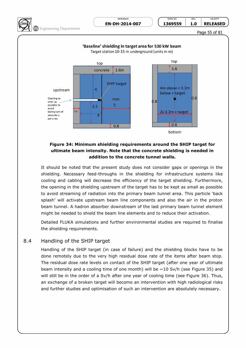
REFERENCE EDMS NO. REV. VALIDITY
EN-DH-2014-007 1369559 1.0 RELEASED
Page 55 of 81
Figure 34: Minimum shielding requirements around the SHIP target for
ultimate beam intensity. Note that the concrete shielding is needed in
addition to the concrete tunnel walls.
It should be noted that the present study does not consider gaps or openings in the
shielding. Necessary feed-throughs in the shielding for infrastructure systems like
cooling and cabling will decrease the efficiency of the target shielding. Furthermore,
the opening in the shielding upstream of the target has to be kept as small as possible
to avoid streaming of radiation into the primary beam tunnel area. This particle ‘back
splash’ will activate upstream beam line components and also the air in the proton
beam tunnel. A hadron absorber downstream of the last primary beam tunnel element
might be needed to shield the beam line elements and to reduce their activation.
Detailed FLUKA simulations and further environmental studies are required to finalise
the shielding requirements.
8.4 Handling of the SHIP target
Handling of the SHIP target (in case of failure) and the shielding blocks have to be
done remotely due to the very high residual dose rate of the items after beam stop.
The residual dose rate levels on contact of the SHIP target (after one year of ultimate
beam intensity and a cooling time of one month) will be ~10 Sv/h (see Figure 35) and
will still be in the order of a Sv/h after one year of cooling time (see Figure 36). Thus,
an exchange of a broken target will become an intervention with high radiological risks
and further studies and optimisation of such an intervention are absolutely necessary.

REFERENCE EDMS NO. REV. VALIDITY
EN-DH-2014-007 1369559 1.0 RELEASED
Page 56 of 81
Figure 35: Residual dose rate (in Sv/h) around the dismantled SHIP target
after one operational year at ultimate intensity and 1 month cool down time.
The beam is impinging the target from the left; only the upper half is shown
in the figure.
Figure 36: Residual dose rate (in Sv/h) of the unshielded SHIP target after
one operational year and different cooling times as a function of radial
distance from the target centre.
8.5 Muon shielding
The SHIP experiment requires a very low level of background in the detector
acceptance. FLUKA simulations have been performed of the passive shield close to the
configuration described in Section 3.2. The baseline muon filter (as shown in Figure 5)
consists of a truncated tungsten cone of 40 m length surrounded by a heavy material
Surface of the target

REFERENCE EDMS NO. REV. VALIDITY
EN-DH-2014-007 1369559 1.0 RELEASED
Page 57 of 81
(here lead) followed downstream by another 30m of heavy shielding material (here
also lead), see Figure 37. With this shielding the muon flux downstream of the muon
filter will be sufficiently low for the experiment (<1.0×10⁴ muons/mm2). However, the
ambient dose equivalent rate outside the ‘extended cone’ will be ~10 Sv/h, see
figure 38. This requires a radiological classification of the detector hall during beam
operation as a Supervised or Simple Controlled Radiation Area.
Figure 37: baseline design of the muon filter.
Figure 38: ambient dose equivalent in the muon absorber and in the detector
hall. Only the upper half of the facility is shown.
The preliminary FLUKA calculations indicate that the upstream part of the muon
absorber will be slightly activated. In addition to dose rate estimates, the use of such
heavy Z material (like Pb, W, etc.) as shielding in areas with the risk of activation will
also require an assessment in terms of specific activities (especially of nuclides
emitting -particles), contamination risks, waste disposal and also toxicological risks.
~ 1
0 u
Sv/h

REFERENCE EDMS NO. REV. VALIDITY
EN-DH-2014-007 1369559 1.0 RELEASED
Page 58 of 81
Consequently, it is strongly recommended to replace at least the lead shielding by iron
keeping the same area density (g/cm2) as used in the case of lead.
Accessible areas outside of the facility should be classified as Non-Designated Areas.
The annual dose to people should not exceed 100 Sv on the CERN site. Members of
the reference group of the public should not receive more than 10 Sv per year. These
limits seem to be achievable with the present shielding and layout.
Additional RP studies (like production of radioactive waste, waste disposal, dismantling
of the facility, etc.) and environmental issues (releases of radioactivity via air or water
pathways, activation of soil, etc.) are not studied yet. This will however be needed at
a later stage of the project.
9. Timeline and Resources
The time line is defined not only by technical and financial constraints, but also by the
operating schedule of the CERN accelerator complex. The construction of the junction
cavern with TDC2 and the transfer tunnel up to the SHIP target area, and the
modification of the splitter region and installation of the proton beam line are critically
linked to Long Shutdown 2. Construction work elsewhere may be performed during
LHC Run 2 and Run 3 with the aim to start beam commissioning and operation of SHIP
during Run 3, with the aim nominal operation in 2023. A preliminary timeline is shown
in Figure 39.
A first and preliminary cost estimate is based on the conceptual design described in
this document and is shown in Table 14. With the exception of civil engineering, this
includes no contingencies. The infrastructure systems have been included as well,
even though no detailed design is available everywhere. In some cases the sizing and
cost is estimated based on similar installations built or studied at CERN.
The rough and very preliminary estimate of the CERN staff manpower is shown in
Table 15. Also the cost of CERN fellows is shown for clarity, but in fact this cost is
already included in the materials budget shown in Table 14. The assumptions used
and the preliminary estimates are appended (unpolished, i.e. as received from the
groups involved) at the end of this document.
The cost for the detectors is separate and is estimated to be of the order of 45 MCHF,
including the tau neutrino detector.

REFERENCE EDMS NO. REV. VALIDITY
EN-DH-2014-007 1369559 1.0 RELEASED
Page 59 of 81
Item Cost [MCHF]
Extraction and proton beam line 19.9
Extraction upgrades, beam interlock 0.4
New MSSB splitter/switch magnets 4.2
Other magnets 1.6
Powering, including cables 6.0
Beam vacuum 3.0
Beam instrumentation 1.9
Beam interlocks 0.4
Other beam line costs 2.4
Target Station 17.1
Target (+spare) plus exchange system 4.6
Hadron absorber 8.1
Helium enclosure of target station 2.0
Removable shielding 0.5
Controls 0.9
Prototypes and testing 1.0
Muon filter 11.0
Muon shield, passive option, reusing 800 t of lead from OPERA 11.0
Civil Engineering 45.1
Junction cavern 5.0
Extraction tunnel 8.4
Target cavern 8.9
Muon filter tunnel 1.9
Experimental cavern 15.1
New access road 0.9
Site investigation 0.2
Studies 0.7
Contingency 4.0
Infrastructure 20.8
Cooling plants 4.9
Ventilation plants 5.1
Electrical infrastructure beam line zone 0.8
Electrical infrastructure target area and muon filter 1.4
Electrical infrastructure detector cavern 1.8
Access system beam lines, target and detector cavern 1.8
Safety systems 1.0
Radiation protection 1.5
Transport: cranes target station, detector cavern, shafts 1.9
Transport and handling 0.6
Total 113.9
Table 14: Material costs for the SHIP facility (excl. detectors), including the cost of fellows.

REFERENCE EDMS NO. REV. VALIDITY
EN-DH-2014-007 1369559 1.0 RELEASED
Page 60 of 81
Item Staff
FTE
Fellows
MCHF
Extraction and proton beam line 31.5 1.5
Extraction upgrades 1 0.1
New MSSB splitter/switch magnets 3 0.2
Other magnets 2
Powering, including cables 12
Beam vacuum 2 0.2
Beam instrumentation 4 0.4
Interlocks 1
Other beam line costs 6.5 0.6
Target Station 35 1.6
Target (+spare) & exchange syst
35
0.6
Hadron absorber 0.6
Helium enclosure of target station
Removable shielding
Controls 0.4
Prototypes and testing
Muon filter
Muon shield, passive opt.,OPERA PB
Civil Engineering 10 0.7
Junction cavern
10
0.7
Extraction tunnel
Target cavern
Muon filter tunnel
Experimental cavern
New access road
Site investigation
Infrastructure 14.4 1.2
Cooling plants 3.0
Ventilation plants 2.0
Electrical infrastructure 1.3 0.8
Access &safety beam lines+detector 1.5
Safety systems 1.3
Radiation protection 4.0 0.4
Transport : cranes, lifts, tooling 1.3
Total 90.9 5.0
Table 15: Very preliminary manpower estimates for the SHIP project. Fellows are listed for information, but their cost is included in Table 14.

REFERENCE EDMS NO. REV. VALIDITY
EN-DH-2014-007 1369559 1.0 RELEASED
Page 61 of 81
Figure 39: The timeline for the SHIP installation

REFERENCE EDMS NO. REV. VALIDITY
EN-DH-2014-007 1369559 1.0 RELEASED
Page 62 of 81
ACKNOWLEDGEMENTS
The authors acknowledge the very important input from many colleagues and
collaborators. Particular thanks go to M.Battistin, J.Bauche, J.Borburgh, J.P.Burnet,
F.Duval, M.De Pablos Herranz, L.Faisandel, A.Ferrari, R.Folch, G.Le Godec,
J.L.Grenard, T.Hakulinen, D.Lafarge, R.Losito, M.Manfredi, M.Meddahi, P.Ninin,
M.Nonis, S.Pelletier, A.Perillo-Marcone, P.Riedo, R.Rinaldesi, I.Ruehl, D.Tommasini and
V.Venturi In many places this study profited from synergies with the CENF study and
we acknowledge the work of its contributors.

REFERENCE EDMS NO. REV. VALIDITY
EN-DH-2014-007 1369559 1.0 RELEASED
Page 63 of 81
R E F E R E N C E S
[1] D. Buttazzo et al., arXiv:hep-ph/1307.3536.
[2] F. Bezrukov, M.Y. Kalmykov, B.A. Kniehl and M. Shaposhnikov, JHEP 10 (2012) 140,
arXiv:hepph/1205.2893.
[3] B. Batell, M. Pospelov and A. Ritz, Phys. Rev. D83 (2011) 054005,
DOI:10.1103/PhysRevD.83.054005, arXiv:hep-ph/0911.4938.
[4] D. S. Gorbunov, Nucl. Phys. B 602 (2001) 213, arXiv:hep-ph//0007325.
[5] A. Dedes, H.K. Dreiner and P. Richardson, Phys. Rev. D65 (2001) 015001,
DOI:10.1103/PhysRevD.65.015001, arXiv:hep-ph/0106199.
[6] A.E. Faraggi and M. Pospelov, Phys. Lett. B458 (1999) 237, DOI:10.1016/S0370-2693(99)00557-2,
arXiv:hep-ph/9901299.
[7] S. N. Gninenko, Phys. Rev. Lett. 103 (2009) 241802, arXiv/hep-ph:0902.3802; S. N. Gninenko and
D. S. Gorbunov, Phys. Rev. D 81 (2010) 075013, arXiv:hep-ph/0907.4666.
[8] T.M. Aliev, A.S. Cornell and N. Gaur, JHEP 07 (2007) 072, DOI:10.1088/1126-6708/2007/07/072,
arXiv:hep-ph/0705.4542.
[9] A.Golutvin et al., « Proposal to Search for Heavy Neutral Leptons at the SPS », CERN-SPSC-2013-
024 ; arXiv :1310.1762 ; SPSC-EOI-010, 7 October 2013.
[10] A. Golutvin et al., « Answers to the questions from the SPSC concerning the SPSC-EOI-010, CERN-
SPSC-2013-024, 3 January 2014.
[11] T. Asaka, S. Blanchet and M. Shaposhnikov, Phys. Lett. B 631 (2005) 151, arXiv:hepph/0503065.
[12] T. Asaka and M. Shaposhnikov, Phys. Lett. B 620 (2005) 17, arXiv:hep-ph/0505013.
[13] E.K. Akhmedov, V.A. Rubakov and A.Y. Smirnov, Phys. Rev. Lett. 81 (1998) 1359,
arXiv:hepph/9803255.
[14] S. Dodelson and L.M. Widrow, Phys. Rev. Lett. 72 (1994) 17, arXiv:hep-ph/9303287.
[15] X.-D. Shi and G.M. Fuller, Phys. Rev. Lett. 82 (1999) 2832, arXiv:astro-ph/9810076.
[16] A. Boyarsky, O. Ruchayskiy and M. Shaposhnikov, Ann. Rev. Nucl. Part. Sci. 59 (2009) 191,
arXiv:hep-ph/0901.0011.
[17] M. Pospelov, A. Ritz and M. B. Voloshin, Secluded WIMP Dark Matter, Phys.Lett. B662 (2008)
53{61 [0711.4866].
[18] G. Arduini et al., 52nd APC meeting (06/10/2005),
https://ab-div.web.cern.ch/ab-div/Meetings/APC/2005/apc051006/minutes_051006.html
[19] G. Arduini et al., 73rd APC meeting (24/11/2006),
https://ab-div.web.cern.ch/ab-div/Meetings/APC/2006/apc061124/minutes_061124.html
[20] V. Kain, Dedicated injection from the SPS and TL powering, LBOC Meeting n. 15, 25/3/2014,
http://indico.cern.ch/event/295939/contribution/1/material/slides/0.pptx
[21] 2011 Injector Accelerator Schedule:
https://espace.cern.ch/be-dep/BEDepartmentalDocuments/BE/injector_schedule.pdf
[22] http://ab-dep-op-sps.web.cern.ch/ab-dep-op-sps/SPSss.html
[23] A. MacPherson, LHC Availability and Performance in 2012, Proceedings of the LHC Beam Operation
Workshop, Evian 17-20 December 2012, S. Dubourg, B. Goddard, eds., p. 1-6.
[24] L.Evans et al.,The external proton beam lines and the splitter systems of the CERN SPS,IEEE
Trans.Nucl.Sci. 24 (1977) 1571.
[25] R.Froeschl et al., Radiological Hazard classification of materia in CERN’s accelerators, EDMS
# 1184236
[26] D.Forkel-Wirth, Zonage radiologique au CERN, EDMS # 810149
[27] Y.Pira and A.Hervé, Cartographi des débits de dose des zones TDC2/TCC2 pour le LS1, Note
Survey 2013-1010, CERN-RP-2013-098-REPORTS-SN v.1, EDMS 1319247 v.1
[28] Prestations sur le Site du CERN, PSO/2011-011/Rev.5, EDMS No.: 1155899

REFERENCE EDMS NO. REV. VALIDITY
EN-DH-2014-007 1369559 1.0 RELEASED
Page 64 of 81
APPENDIX I
General RP guidelines
A few general guidelines (non-exhaustive) have to be followed in order to design and
build a facility being compatible with CERN’s radiation protection regulation: ALARA
(optimization) starts already at the design phase
● The design of the entire facility must not only respect legal dose limits but must
also satisfy the optimization principle (ALARA) with respect to individual and
collective doses for workers and the public. The design goals for individual and
collective doses are valid for commissioning, normal beam operation, maintenance
and accidents.
● Use ‘correct/good’ materials with respect to activation - the ActiWiz material
catalogue should be consulted [25].
● Install only absolutely necessary equipment in areas of high radiation levels.
Equipment has to be able to withstand these high radiation levels.
● Minimize air volumes in areas of high levels of prompt radiation or even better use
a Helium environment or vacuum environment.
● Complete separation of different air volumes, i.e. separate the air in the target
area, from adjacent areas and outside; static (e.g., sealing of air volumes) and
dynamic (e.g., leak extraction) air confinement are key elements.
● Pressure cascade (Onion Principle) is required, i.e. air pressure has to be lowest in
the area with the highest radiological risk, higher in adjacent areas and highest
outside of the facility.
● Treatment of air in the target area: a ‘closed’ ventilation circuit has to be used and
HEPA filters have to be installed in the air handling units of this circuit. The air
exhaust of the target area needs to be equipped with HEPA filters too and the air
borne radioactivity released into the environment needs to be monitored.
● Separate closed cooling circuits for highly radioactive elements (like target and
dump cooling) have to be foreseen.
● Water sumps in areas with high concentration of tritium have to be avoided. Don’t
install A/C ventilation units in areas with increased tritium concentration in air.
● Avoid installation of the facility in a ‘wet’ area. A hydrological study is a pre-
requisite.
● Avoid activation and/or contamination of ground water and earth.
● Soil samples should be taken and analysed for their chemical and radiological
composition (especially close to TDC2 and TCC2).
● Foresee remote maintenance/repair if residual dose rates are too high for manual
interventions. Optimize any component such that maintenance time and repair
needs are minimized.
● The design must consider aspects of radioactive waste disposal.

REFERENCE EDMS NO. REV. VALIDITY
EN-DH-2014-007 1369559 1.0 RELEASED
Page 65 of 81
APPENDIX II
In Chapter 9 of this document a summary of resource estimates and a time line are
given for the design and construction of the SHIP facility on the Prévessin site of CERN.
The technical description of the facility is provided in the main document.
All cost and manpower estimates given are preliminary and there are some uncertainties.
Cost estimates are in 2014 prices. They do not include contingencies, with the exception
of the Civil Engineering cost.
The estimates are based on contributions from the different groups. However, in Table 14
infrastructure systems costs (electrical, cooling and ventilation, access and safety,
handling and transport systems) are removed from the individual contributions for the
beam line and target station teams and they show up under infrastructure systems costs
and the estimates from the infrastructure system providers supersede the corresponding
estimates by the accelerator teams. Industrial labour is included in the material cost. So
are fellows, although they are marked for information and expressed in money (at
120 kCHF/year) in the manpower table. CERN manpower is expressed in FTE (= man-
years).
The costs of the experiment have not evolved since the presentation of the detector costs
to the SPSC referees in January, with the exception of the additional emulsion detector
for tau neutrino physics. Therefore the detector cost has gone up from ~30 to 45 MCHF.
The individual contributions to the cost and resource estimates are given ‘as received’,
i.e. without polishing and without modifications for consistency.

REFERENCE EDMS NO. REV. VALIDITY
EN-DH-2014-007 1369559 1.0 RELEASED
Page 66 of 81
APP.II-1: EXTRACTION AND BEAM LINE (Source: B.Goddard)

REFERENCE EDMS NO. REV. VALIDITY
EN-DH-2014-007 1369559 1.0 RELEASED
Page 67 of 81
Year Material (kCHF) Manpower
(CERN FTE)
2015 0 3.5
2016 1543 7.0
2017 4850 7.0
2018 8157 7.0
2019 6393 7.0
2020 1102 3.5
2021 0 2.0
For the power consumption of the SHIP beamline TE/ABT provided the following information:
- water cooling 1.7 MW
- air cooling 75 kW
These estimates are based on 14 main dipoles, 7 main quadrupoles, 7 correctors and 2 dilution magnets.
It is assumed that only the main dipoles have water cooled cables - all the others have normal cables, which
generates the heat the air cooling needs to evacuate.
They didn't take any margin nor include any other equipment, so maybe 2 MW water and 100 kW air would
be minimum numbers, plus what you normally add as margin.
They also assumed all magnets are DC - in reality they may be cycled, which makes things better.
Electrical power 1764 kW
Water cooling 1690 kW
Air cooling 74 kW

REFERENCE EDMS NO. REV. VALIDITY
EN-DH-2014-007 1369559 1.0 RELEASED
Page 68 of 81

REFERENCE EDMS NO. REV. VALIDITY
EN-DH-2014-007 1369559 1.0 RELEASED
Page 69 of 81
App.II-2: Target station and Hadron absorber (source M.Calviani)
Target, hadron absorber and target station MCHF
Target head + spare 3.5
Target exchange system 0.5
Target cooling system (400 kW) 2.0
Hadron absorber + radiation shielding, iron blocks, (500 m3, density 7.2),15 kCHF/m3 7.5
Hadron absorber cooling system (100 kW) 1.0
Helium atmosphere system and tank 2.0
Concrete removable shielding - 1 kCHF/m3 (400 m3 + cont.) 0.5
Ventilation system 2.0
Access and safety system 0.5
Radiation protection system 1.0
General safety systems (fire detection, ODH, emergency stops, signs, etc) 0.5
Overhead crane and backup crane + special lifting tools 1.2
Electrical infrastructure 0.4
Controls 0.5
Prototype and testing 1.0
Total 24.1
Considering the budget of the order of 20 MCHF for the whole target station area (excluding
the civil engineering part), EN/STI thinks that about 35 FTE will be required for the design and
construction of the production target as well as of the target station area with services (CE
excluded).
At this stage they are in a position to be more precise on both aspects (e.g. sharing between
staff/ fellows/PJ and technical infrastructures).
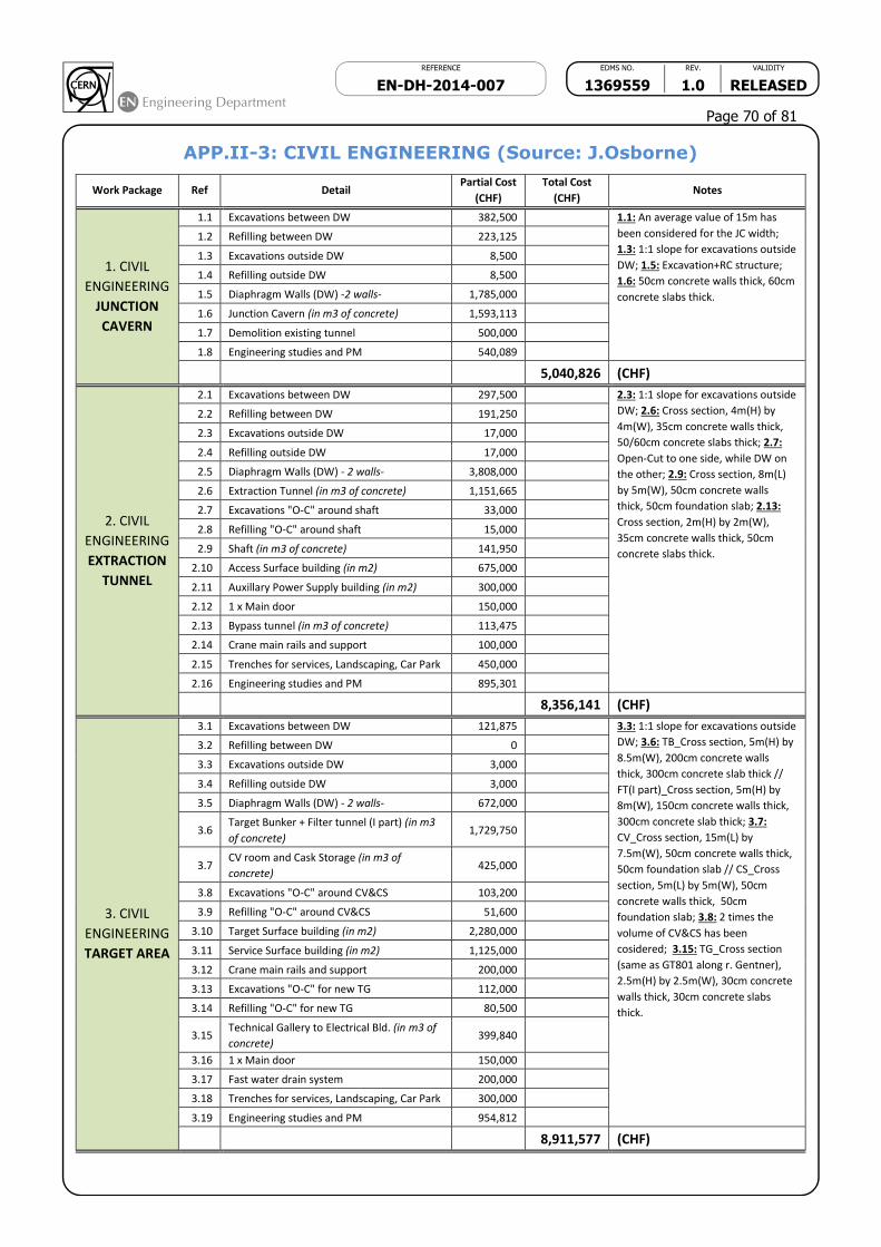
REFERENCE EDMS NO. REV. VALIDITY
EN-DH-2014-007 1369559 1.0 RELEASED
Page 70 of 81
APP.II-3: CIVIL ENGINEERING (Source: J.Osborne)
Work Package Ref Detail Partial Cost
(CHF)
Total Cost
(CHF) Notes
1. CIVIL
ENGINEERING
JUNCTION
CAVERN
1.1 Excavations between DW 382,500 1.1: An average value of 15m has
been considered for the JC width;
1.3: 1:1 slope for excavations outside
DW; 1.5: Excavation+RC structure;
1.6: 50cm concrete walls thick, 60cm
concrete slabs thick.
1.2 Refilling between DW 223,125
1.3 Excavations outside DW 8,500
1.4 Refilling outside DW 8,500
1.5 Diaphragm Walls (DW) -2 walls- 1,785,000
1.6 Junction Cavern (in m3 of concrete) 1,593,113
1.7 Demolition existing tunnel 500,000
1.8 Engineering studies and PM 540,089
5,040,826 (CHF)
2. CIVIL
ENGINEERING
EXTRACTION
TUNNEL
2.1 Excavations between DW 297,500 2.3: 1:1 slope for excavations outside
DW; 2.6: Cross section, 4m(H) by
4m(W), 35cm concrete walls thick,
50/60cm concrete slabs thick; 2.7:
Open-Cut to one side, while DW on
the other; 2.9: Cross section, 8m(L)
by 5m(W), 50cm concrete walls
thick, 50cm foundation slab; 2.13:
Cross section, 2m(H) by 2m(W),
35cm concrete walls thick, 50cm
concrete slabs thick.
2.2 Refilling between DW 191,250
2.3 Excavations outside DW 17,000
2.4 Refilling outside DW 17,000
2.5 Diaphragm Walls (DW) - 2 walls- 3,808,000
2.6 Extraction Tunnel (in m3 of concrete) 1,151,665
2.7 Excavations "O-C" around shaft 33,000
2.8 Refilling "O-C" around shaft 15,000
2.9 Shaft (in m3 of concrete) 141,950
2.10 Access Surface building (in m2) 675,000
2.11 Auxillary Power Supply building (in m2) 300,000
2.12 1 x Main door 150,000
2.13 Bypass tunnel (in m3 of concrete) 113,475
2.14 Crane main rails and support 100,000
2.15 Trenches for services, Landscaping, Car Park 450,000
2.16 Engineering studies and PM 895,301
8,356,141 (CHF)
3. CIVIL
ENGINEERING
TARGET AREA
3.1 Excavations between DW 121,875 3.3: 1:1 slope for excavations outside
DW; 3.6: TB_Cross section, 5m(H) by
8.5m(W), 200cm concrete walls
thick, 300cm concrete slab thick //
FT(I part)_Cross section, 5m(H) by
8m(W), 150cm concrete walls thick,
300cm concrete slab thick; 3.7:
CV_Cross section, 15m(L) by
7.5m(W), 50cm concrete walls thick,
50cm foundation slab // CS_Cross
section, 5m(L) by 5m(W), 50cm
concrete walls thick, 50cm
foundation slab; 3.8: 2 times the
volume of CV&CS has been
cosidered; 3.15: TG_Cross section
(same as GT801 along r. Gentner),
2.5m(H) by 2.5m(W), 30cm concrete
walls thick, 30cm concrete slabs
thick.
3.2 Refilling between DW 0
3.3 Excavations outside DW 3,000
3.4 Refilling outside DW 3,000
3.5 Diaphragm Walls (DW) - 2 walls- 672,000
3.6 Target Bunker + Filter tunnel (I part) (in m3
of concrete) 1,729,750
3.7 CV room and Cask Storage (in m3 of
concrete) 425,000
3.8 Excavations "O-C" around CV&CS 103,200
3.9 Refilling "O-C" around CV&CS 51,600
3.10 Target Surface building (in m2) 2,280,000
3.11 Service Surface building (in m2) 1,125,000
3.12 Crane main rails and support 200,000
3.13 Excavations "O-C" for new TG 112,000
3.14 Refilling "O-C" for new TG 80,500
3.15 Technical Gallery to Electrical Bld. (in m3 of
concrete) 399,840
3.16 1 x Main door 150,000
3.17 Fast water drain system 200,000
3.18 Trenches for services, Landscaping, Car Park 300,000
3.19 Engineering studies and PM 954,812
8,911,577 (CHF)
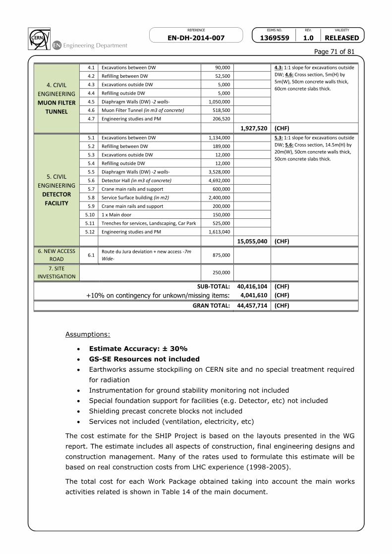
REFERENCE EDMS NO. REV. VALIDITY
EN-DH-2014-007 1369559 1.0 RELEASED
Page 71 of 81
4. CIVIL
ENGINEERING
MUON FILTER
TUNNEL
4.1 Excavations between DW 90,000 4.3: 1:1 slope for excavations outside
DW; 4.6: Cross section, 5m(H) by
5m(W), 50cm concrete walls thick,
60cm concrete slabs thick.
4.2 Refilling between DW 52,500
4.3 Excavations outside DW 5,000
4.4 Refilling outside DW 5,000
4.5 Diaphragm Walls (DW) -2 walls- 1,050,000
4.6 Muon Filter Tunnel (in m3 of concrete) 518,500
4.7 Engineering studies and PM 206,520
1,927,520 (CHF)
5. CIVIL
ENGINEERING
DETECTOR
FACILITY
5.1 Excavations between DW 1,134,000 5.3: 1:1 slope for excavations outside
DW; 5.6: Cross section, 14.5m(H) by
20m(W), 50cm concrete walls thick,
50cm concrete slabs thick.
5.2 Refilling between DW 189,000
5.3 Excavations outside DW 12,000
5.4 Refilling outside DW 12,000
5.5 Diaphragm Walls (DW) -2 walls- 3,528,000
5.6 Detector Hall (in m3 of concrete) 4,692,000
5.7 Crane main rails and support 600,000
5.8 Service Surface building (in m2) 2,400,000
5.9 Crane main rails and support 200,000
5.10 1 x Main door 150,000
5.11 Trenches for services, Landscaping, Car Park 525,000
5.12 Engineering studies and PM 1,613,040
15,055,040 (CHF)
6. NEW ACCESS
ROAD 6.1
Route du Jura deviation + new access -7m
Wide- 875,000
7. SITE
INVESTIGATION 250,000
SUB-TOTAL: 40,416,104 (CHF)
+10% on contingency for unkown/missing items: 4,041,610 (CHF)
GRAN TOTAL: 44,457,714 (CHF)
Assumptions:
Estimate Accuracy: ± 30%
GS-SE Resources not included
Earthworks assume stockpiling on CERN site and no special treatment required
for radiation
Instrumentation for ground stability monitoring not included
Special foundation support for facilities (e.g. Detector, etc) not included
Shielding precast concrete blocks not included
Services not included (ventilation, electricity, etc)
The cost estimate for the SHIP Project is based on the layouts presented in the WG
report. The estimate includes all aspects of construction, final engineering designs and
construction management. Many of the rates used to formulate this estimate will be
based on real construction costs from LHC experience (1998-2005).
The total cost for each Work Package obtained taking into account the main works
activities related is shown in Table 14 of the main document.
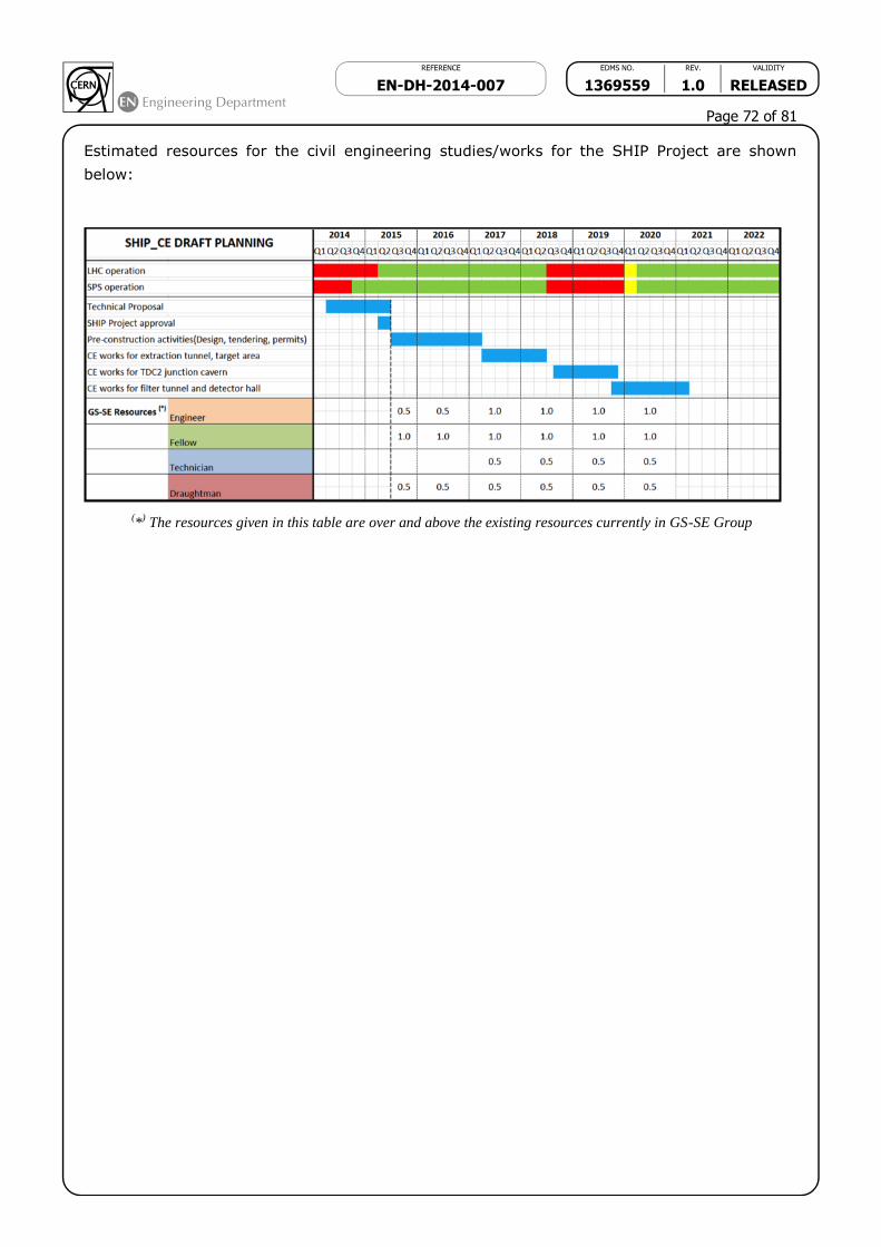
REFERENCE EDMS NO. REV. VALIDITY
EN-DH-2014-007 1369559 1.0 RELEASED
Page 72 of 81
Estimated resources for the civil engineering studies/works for the SHIP Project are shown
below:
(*
) The resources given in this table are over and above the existing resources currently in GS-SE Group

REFERENCE EDMS NO. REV. VALIDITY
EN-DH-2014-007 1369559 1.0 RELEASED
Page 73 of 81
App.II-4: Cooling and Ventilation infrastructure (Source: M.Nonis)
Please find hereunder a rough estimate of the cost for CV plants for SHIP, made on the basis
of the information received and the short time available to make the work.
Cooling plants: Total cost: 4’900 kCHF
Manpower: 2 FTE (CP E) + 1 FTE (CP C) (other supervision and drawing work is
included in the material cost).
Remarks:
o Standard solution for cooling: deltaT 10 °C, 25 °C inlet, redundancy….
o Inlet pressure and delta p not known.
o Cooling tower: additional cell to bldg 893, cooling power around 8 MW, not
in concrete as the other ones
o Civil engineering costs (trenches for piping, slabs, passages through walls
etc.) not included
o routing of piping to be checked.
o circuit target: delta T by 10 °C tbc; to control very low level of conductivity
100% flow through cartridges and more powerful
pump ,therefore additional cost (100+20 kCHF?)
o circuit target: if degasing for all flow +100 kCHF (very preliminary estimate,
not possible to know until a layout will exist)
Tolerance: ± 30%
Ventilation plants : Total cost : 5'100 kCHF
Manpower : 2 FTE (CP E + 1 FTE (CP C) (other supervision and drawing work is
included in the material cost).
Remarks :
o The ventilation of the target complex is based on the input received for the
CENF study
o It is supposed that the thermal load in the Junction cavern does not require
a dedicated ventilation but the one existing at present is sufficient.
o No control on humidity foreseen.
o Ambient conditions: similar to industrial halls
o Routing of ducts needs to be verified when further details on the premises
will be available.
o Civil engineering costs for CV plants not included.
General remark: It is not possible to define the needed surface for the CV plants or, whether the
allocated areas are sufficient.
Layout of the cooling and ventilation stations not defined, to be detailed further.
REFERENCE EDMS NO. REV. VALIDITY
EN-DH-2014-007 1369559 1.0 RELEASED
Page 74 of 81
App.II-5: Electrical infrastructure costs (Source: F.Duval)
SHIP Experiment - Electrical power supply description:
The following electrical power supply configuration is proposed for the SHIP experiment and
associated infrastructure.
Creation of a new HV Electrical substation within the main service building to supply
new stable and pulsed loads associated with the experiment.
Installation of new 18kV/0.4kV cast resin transformers to supply power converter,
experiment and general services loads
Dual redundant UPS to be located within the Target Hall Service Building, serving the
whole facility
Installation of EL SCADA monitoring equipment to supervise the new infrastructure.
Installation of AUG buttons within each of the buildings as a pre-requisite for safe
operation of the facility.
Electrical containment, normal lighting, emergency lighting and power distribution to
new underground areas and technical galleries
Dedicated 48V DC system to supply new electrical infrastructure.
Future extension of the secure power network on the Prevessin site to provide power
for critical process and life safety requirements within the new complex.
The electrical distribution as proposed will require the creation of a trench linking all three
proposed buildings to allow the distribution of electrical power and control cables away from
radioactive areas within the tunnel.
Access Building
Power converter loads will be supplied from the pulsed network via two 18kV/0.4kV
transformers, connected to two dedicated Type 4 electrical switchboards. Low voltage general
services will be supplied from a low voltage cable feed from the Target Hall Service Building,
supplying a Type 2 electrical distribution board. A low voltage interconnect will be provided to
the pulsed network to re-supply of general services in a reduced power mode during
maintenance of the transformer in the service building or an extended network failure.
Equipment supplied from the general services distribution within the Access Building will
include:
Gantry crane
Cooling and ventilation supplies
Auxiliary supplies for power converters
General lighting and small power for the surface building
General lighting and small power for the extraction tunnel
A low voltage feed from the secure power network will be provided to supply life safety loads,
derived from a 3.3kV/0.4kV transformer located external to the main service building. A Type
3 electrical switchboard will be located external to the access building, consistent with the
philosophy for life safety power distribution as employed throughout the SPS complex.

REFERENCE EDMS NO. REV. VALIDITY
EN-DH-2014-007 1369559 1.0 RELEASED
Page 75 of 81
Target Hall and Service Building
The access building will contain a new high voltage substation for the distribution of pulsed and
stable power to the SHIP experimental complex. Two 18kV switchboards will provide high
voltage Pulsed and Stable distribution to the Access Building, the Target Hall and Service
Building and the Experimental Zone. The new high voltage switchboards shall be located within
a dedicated room and shall include 25% spare capacity for future expansion, with 2 spare
circuit breakers provided for each network. The electrical substation will include a dedicated
48V DC distribution system to support the experiment and an EL SCADA data acquisition rack
to allow the supervision of all electrical equipment installed within the complex.
Low voltage general services will be supplied by an 18kV/0.4kV transformer situated externally
to the Service Building, with a Type 1 electrical distribution board located within the building
for distribution. A low voltage interconnect will be provided to the Access Building to supply
general services power for normal operation. Equipment within the Target hall and Service
Building supplied from the general services distribution will include:
Gantry crane
Cooling and ventilation supplies
General lighting and small power for the surface building
General lighting and small power for the underground target areas
Dual redundant 20kVA UPS installed to provide power to sensitive loads (Fire detection
equipment, PLC’s, IT Star Points etc.)
A low voltage feed from the secure power network will be provided from a pre-fabricated
electrical substation including a 3.3k/0.4kV transformer and a Type 2 electrical switchboard.
This substation will supply secure power to Type 3 Switchboards located outside the Access
Building, the Target hall and Service Building and the Experimental zone via low voltage
cables, in a manner consistent with the philosophy for life safety power distribution as
employed throughout the SPS complex.
Emergency lighting for all areas of the new infrastructure will be provided by dual redundant
AES units supplied from the secure power network at low voltage, with fire resistant cable
distribution throughout the surface and underground areas.
Experimental Zone
Power converter loads for experiment magnets will be supplied from the pulsed network via
two 18kV/0.4kV transformers, connected to two dedicated Type 4 electrical switchboards. The
experimental zone will be supplied from two 18kV/0.4kV transformers, one dedicated to
general services provision and another reserved for experimental loads.
Low voltage general services will be supplied by an 18kV/0.4kV transformer situated externally
to the Experimental Zone, with a Type 1 electrical distribution board located within the building
for distribution. A low voltage interconnect will be provided to the experiment distribution to
allow the re-supply of general services in a reduced power mode during transformer
maintenance. Equipment supplied from the general services distribution within the access
building will include:
Gantry crane
Cooling and ventilation supplies
General lighting and small power for the surface building
General lighting and small power for the extraction tunnel
Experimental loads (Racks, detector electronics etc.) will be supplied from dedicated Type 1
and Type 2 distribution boards located within the experimental zone surface access building.

REFERENCE EDMS NO. REV. VALIDITY
EN-DH-2014-007 1369559 1.0 RELEASED
Page 76 of 81
A low voltage feed from the secure power network will be provided from the Service Building
to a Type 3 electrical switchboard will be located external to the Experimental Zone.
Basis for design
This outline description, single line diagram and electrical budget are based on the draft
information for the project available at the time of writing. Changes to the scale and scope of
the project will have implications for the provision of electrical infrastructure. Approximately
100m of additional trenches will be required to permit the installation of the electrical
infrastructure as described, not currently included in the civil engineering proposals.
SHIP Experiment: Load schedule 5/23/14

REFERENCE EDMS NO. REV. VALIDITY
EN-DH-2014-007 1369559 1.0 RELEASED
Page 77 of 81

REFERENCE EDMS NO. REV. VALIDITY
EN-DH-2014-007 1369559 1.0 RELEASED
Page 78 of 81
APP.II-6: Access system costs (Source: P.Ninin)
Please find below a draft cost estimate for the SHIP Experiment.
SHIP (Search for HIdden Particles) is a new fixed-target experiment that should be connected
to the SPS to search for Heavy Neutral Leptons and other hidden very weakly interacting
particles.
Time-line: 2015-2017: R&D, civil engineering; LS2: connection of extraction line to the
SPS; starting detector installation, >2020 fist beam; >2023 data taking.
The facility is made of:
- a primary area that should be connected after the TT20 at the TDC2 level . It will
consist of a junction cavern (85m), an extraction tunnel (170m) served by an access
building, delivering beam to a Target Hall (40m*20m) equipped also with an access
point, the particle continue in a “Filter tunnel”. No door between the Target Hall and
Filter Tunnel.
- a secondary area : a 150m* 20m Detector facility is located at the end of the Filter
tunnel. From the drawing we see only one single access point for the underground
and Detector Hall.
Main risks: radiation, the levels that are necessary to determine the Safety Integrity Level of
the facility will be given by a Fluka simulation done at a later stage.
Determining also the border between the primary and the secondary areas.
Proposed Personnel Protection System:
Redundant safety system (path A: PLC based, Path B hardwired logic), compliant with
the Regulatory body requirements (INB, OFSP).
Patrol mechanism, safety token, interface with ventilation, evacuation system.
Public Address,
3 complete access points, 10 EIS access, search boxes,
Access Point made of a Personnel Access Device, Material Access Device, Mini-MAD,
Biometry check, Single Passage Check, Emergency door.
Remote monitoring from CCC; local monitoring and key delivery from Detector control
room.
A global estimate is given according to the cost of the Personnel Protection System of recent
similar size facilities, it covers the 3 zones and includes power supplies, cabling and the optical
fibres cabinets.
As one system covers the functionalities of the primary area and the Detector Hall, one single
quote is given.
Man Power: 1.5 Man/year
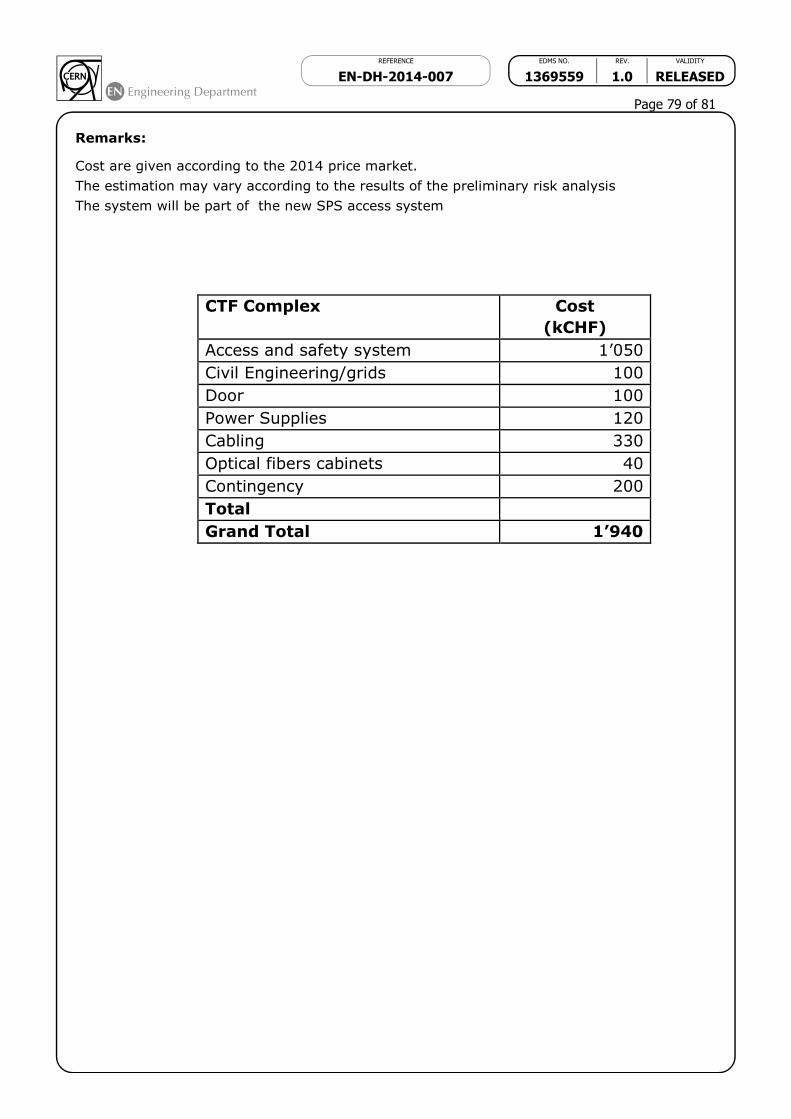
REFERENCE EDMS NO. REV. VALIDITY
EN-DH-2014-007 1369559 1.0 RELEASED
Page 79 of 81
Remarks:
Cost are given according to the 2014 price market.
The estimation may vary according to the results of the preliminary risk analysis
The system will be part of the new SPS access system
CTF Complex Cost
(kCHF)
Access and safety system 1’050
Civil Engineering/grids 100
Door 100
Power Supplies 120
Cabling 330
Optical fibers cabinets 40
Contingency 200
Total
Grand Total 1’940

REFERENCE EDMS NO. REV. VALIDITY
EN-DH-2014-007 1369559 1.0 RELEASED
Page 80 of 81
App.II-7: Safety systems other than access
Ci dessous les estimations en KCHF et Man/Month qui avait été faite pour le projet SBLNF
(CENF) pour les autres systèmes de sûreté, pas aussi cher que l'accès mais malgré tout
environ 1 MCHF et 16 Man/Month.
Item Cost
(kCHF)
Man-
Months
SUSI + video 150 2
Evacuation 150 2
SIP panel 10 1
BIW 150 2
ODH 2.0 60 160 3
Fire detection 250 3
Red telephone 50 1
Upgrade CSAM / MMD 30 2
Total 950 16

REFERENCE EDMS NO. REV. VALIDITY
EN-DH-2014-007 1369559 1.0 RELEASED
Page 81 of 81
App.II-8: Transport and Handling (Source: R.Rinaldesi, I.Ruehl)
Please find below a table with the cost estimation for handling needs in the SHIP project. The
FTE item covers CERN staff engagement for technical specification, contract management and
installation follow-up.
We agreed that an additional 5 ton overhead crane (crane n.4) could be useful for the
installation activities inside the filter tunnel; as you can see it doesn’t increase sensibly the
total cost, so I guess it’s wise to leave it in for the moment.