a new approach for minimization of torque ripple in 8/6 … · · 2016-04-23international...
TRANSCRIPT

International Research Journal of Engineering and Technology (IRJET) e-ISSN: 2395 -0056
Volume: 03 Issue: 03 | Mar-2016 www.irjet.net p-ISSN: 2395-0072
© 2016, IRJET | Impact Factor value: 4.45 | ISO 9001:2008 Certified Journal | Page 81
A New approach for minimization of torque ripple in 8/6 switched reluctance motor
Pranil S. Warpatkar1, Harshit S. Dalvi2
1M. Tech. (PED) Student, Department of Electrical Engg., G. H. Raisoni College of Engg., Nagpur 440 016, India 2Research Scholar, Department of Electrical Engineering G.H. Raisoni college of Engineering, Nagpur 440 016,
India
---------------------------------------------------------------------***---------------------------------------------------------------------
Abstract - Switched Reluctance Motor (SRM)has becomes popular in various industries because of increasing cost of permanent magnet as it has concentrated winding on each and every pole also it has salient structure therefore SRM is a low cost extremely robust variable speed motor. In this paper new method is introduced to minimize torque ripple and improve the accuracy.
Key Words: Switched reluctance motor, Torque ripple, Key word3, etc (Minimum 5 to 8 key words)…
1.INTRODUCTION Now a days switched reluctance motor (SRM) has great demand in fields living, industry and transportation because of its high efficiency and accuracy. So there should be modification of size and weight, torque and Efficiency of motors is required. AC motor has achieved the same controllability as a conventional DC Motor due to the advancement and modification in power electronics technology. Major advancement have taken place viz induction motor and permanent magnet synchronous motor have received practical application due to simple and robust structure and maintenance free. SRM also expected low cost extremely robust and it has application in Hybrid electric vehicle and electric vehicle. For low cost variable speed applications the two SRM which is single phase with a two switch based asymmetric converter and two phases with two switch based split supply converter are found to be competitive. There are many applications of this drive i. e. Reduction in cost and component which would be highly appealing for Industry. It is also necessity to meet highly cost sensitive and high volume application. The new converters are more modified than original converter. They can recover the energy from main winding and it is Utilized instead of returning to the source. The motor and source causes extra losses due to the energy circulation. It can also reduce the life time as well as there can be need of larger DC link capacitor. DC bus or an AC line can not help SRMs to run just like the brushless DC Motor and normal induction motor. To control the SRM and produce a torque saliency of stator and rotor is important. Industry acceptance of SRM is slow due to the combinations of pursuit difficulty of SRM. They cannot be
easily available in market to operate with traditional AC and DC machines. [1]
SRM is rarely found in the factory but it is more popular due to their reliability and modification in electric machine technology. Very few practitioners are successful with SRM while others are complaining about there in correction. It is the machine, tendency of moveable part produces torque and it is moved where the inductance of excited winding is maximized. The SRM has both stator and rotor has salient poles and it operates like variable reluctance stepper motor. The main part of this motor is electronic drive and controller by which it cannot work. SRM is given its name because of switching which use in controller. [2]
2. PRINCIPLE OF OPERATION Both stator and rotor of switched reluctance motor (SRM) have salient poles. There are no coils and magnets in rotor side. The stator of SRM has simple concentric winding. In SRM there are different combinations like 6:4, 8:6, 12:8, 16:12 etc. The structure of 8:6 SRM shows in figure (1). The current reluctance has minimum value when rotor of an SRM is in aligned position with respect to fixed phase. The current reluctance has maximum value when the rotor of SRM is in unaligned position with respect to the fixed phase. The maximum stator and rotor poles number causes less torque ripple. To achieve lower switching frequency and higher starting torque of power converter the combinations should be the number of stator poles are more than rotor poles by two. The rotor pole pair is get attracted towards stator pole pair where the value of reluctance is very less in magnetic path. The phase winding energized the stator pole pair. The direction of rotation can be achieved in either direction by energizing the consecutive stator phase in sequence. Assuming only one switched ON (exited) initially. The above explanation gives direction of the rotor clockwise to nearest aligned position. I is the current in the phase A When it is switched ON the rotor comes to aligned position then phase D is switched ON. Similarly when rotor comes to unaligned position then phase C is switched ON and rotor continues to rotate in clockwise direction.

International Research Journal of Engineering and Technology (IRJET) e-ISSN: 2395 -0056
Volume: 03 Issue: 03 | Mar-2016 www.irjet.net p-ISSN: 2395-0072
© 2016, IRJET | Impact Factor value: 4.45 | ISO 9001:2008 Certified Journal | Page 82
If excitation sequence frequency stator phase is varied the speed of SRM drive is changed the fundament switching frequency can be expresses follows,
Fig -1: 8/6 SRM
f=Nrωr Where,
Nr = Number of rotor poles. ωr = Angular rotor speed.
The rotor tends to move by the torque when stator winding has current flowing through it. Rotor rotates in such direction to increase the inductance. It will continue to rotate until the maximum inductance is achieved. When there is no residual magnetization in steel, the current has unipolar direction. The nearest aligned position determine the direction of the torque. When the rotor is in between unaligned and aligned position in forward direction produces motoring torque (positive torque). For motoring mode it is important to make stator phase turn off before the region where increasing inductance ends. In this case, current falls to zero and produces no negative torque.
3. MATHEMATICAL MODELING The consideration of elementary reluctance machine is used for the derivation of basic torque equation of SRM. The carries only one winding of the stator as machine is single phase excited. The rotor freely rotates as the excited winding is wound on the stator.
The flux linkage is, ψ= L(θ)i
The general torque expression
Where, = co-energy
If we considered the co-energy at any position, it can be defined as area below the magnetization curve. It can also be defined as the definite integral
So, torque equation becomes
The instantaneous torque can be visualized graphically for
this kind of equation where, is involved at
constant stator current because move through infinite terminal displacement .
During some displacement changes occur, Exchange of energy with power supply. Also change in stored field energy. Change in co-energy is exactly equal to mechanical
work done. This can be proved as ,Constant current in a displacement ,
the energy exchange with supply energy is . The
change in stored field energy and
mechanical work done is,
We find that all of the energy is not converted into mechanical work and some kind of energy is stored in magnetic field. This energy which stored in magnetic field is useful it can’t be wasted. The magnetization curve can be straight line if magnetic saturation doesn’t occur. The instantaneous torque,
Φ
Φ/2Φ/2
Rc RcRL
Fig -2: Magnetic circuit for SRM

International Research Journal of Engineering and Technology (IRJET) e-ISSN: 2395 -0056
Volume: 03 Issue: 03 | Mar-2016 www.irjet.net p-ISSN: 2395-0072
© 2016, IRJET | Impact Factor value: 4.45 | ISO 9001:2008 Certified Journal | Page 83
4. TORQUE GENERATIONS AND IT’S OUTPUTS The equation of SRM is case of electromechanical energy conversion are given by, Equation of voltage for single phase
V = e + Ri i. e. e = v - Ri Where,
i - Current R- Resistance v- Terminal voltage e- Back EMF
Faradays low is rate of change of flux linkage(ψ) For back EMF,
e =
i.e. = (v- Ri)
For constant speed,
e = = ωm
Where, ωr- Angular Velocity
ψ - Flux Linkage In SRM both stator and rotor have salient poles. The relation in between current and flux linkage is non linear due to magnetic saturation and it is also depends on rotor position. Consider moment that there is no mutual coupling in between phase. We can write ψ (i ,θ) and it represented set of curve of ψ verses i with θ as parameter which shown in figure 3
Flux-linkage
Current i [A]
A
U
[mV-s]
Fig -3: Magnetization Curves
In figure 3 showing flux linkage ψ as a function of phase current i at different rotor position θand U is for unaligned and A for aligned.
The area covered by ‘W’ is in the electrical energy converted to mechanical energy or vice versa. Average torque,
Te(avg) =
Where, S – Number of stroke per revolution
Nr – Number of rotor pole Φ – Number of phase S = NrΦ
It is noted that by increasing number of rotor pole output of torque also get increased as per phases given. All machines (3,4,5 phases SRM) is having approximately same copper loss along with same dimensions. As this motor having high number of phases then it develops positive torque producing zone simultaneously with two phases. Hence we can excite two phases at the same time. Table -1: Motor Data
Parameters Values
Number of stator poles(Ns) 8
Number of rotor poles(Nr) 6
Number of phases(Φ) 4
Angel of stator pole(βs) 25
Angel of rotor pole(βr) 27
Frequency(F) 50 Hz
Voltage (V) 240
5. SIMULATION RESULTS Results for 6/4 and 8/6 SRM is shown in Fig.4-9. From below results the torque ripple in 8/6 SRM is less than 6/4 SRM.
International Research Journal of Engineering and Technology (IRJET) e-ISSN: 2395 -0056
Volume: 03 Issue: 03 | Mar-2016 www.irjet.net p-ISSN: 2395-0072
© 2016, IRJET | Impact Factor value: 4.45 | ISO 9001:2008 Certified Journal | Page 84
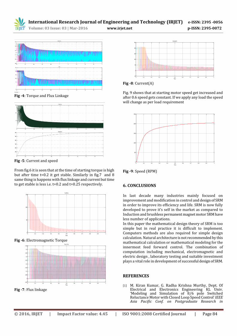
Fig -4: Torque and Flux Linkage
Fig -5: Current and speed From fig.6 it is seen that at the time of starting torque is high but after time t=0.2 it get stable. Similarly in fig.7 and 8 same thing is happens with flux linkage and current but time to get stable is less i.e. t=0.2 and t=0.25 respectively.
0 0.1 0.2 0.3 0.4 0.5 0.6 0.7 0.8 0.9 10
50
100
150
Time
Te (N*m)
Fig -6: Electromagnetic Torque
0 0.1 0.2 0.3 0.4 0.5 0.6 0.7 0.8 0.9 1-0.05
0
0.05
0.1
0.15
0.2
0.25
0.3
0.35
0.4
0.45
Time
Flux (V*s)
Fig -7: Flux linkage
0 0.1 0.2 0.3 0.4 0.5 0.6 0.7 0.8 0.9 1-50
0
50
100
150
200
250
Time
Current(A)
Fig -8: Current(A) Fig. 9 shows that at starting motor speed get increased and after 0.6 speed gets constant. If we apply any load the speed will change as per load requirement
0 0.1 0.2 0.3 0.4 0.5 0.6 0.7 0.8 0.9 10
500
1000
1500
2000
2500
Time
Fig -9: Speed (RPM)
6. CONCLUSIONS In last decade many industries mainly focused on improvement and modification in control and design of SRM in order to improve its efficiency and life. SRM is now fully developed to prove it’s self in the market as compared to Induction and brushless permanent magnet motor SRM have less number of applications. In this paper the mathematical design theory of SRM is too simple but in real practice it is difficult to implement. Computers methods are also required for simple design calculation. Natural architecture is not recommended by this mathematical calculation or mathematical modeling for the innermost feed forward control. The combination of computation including mechanical, electromagnetic and electric design , laboratory testing and suitable investment plays a vital role in development of successful design of SRM.
REFERENCES [1] M. Kiran Kumar, G. Radha Krishna Murthy, Dept. Of
Electrical and Electronics Engineering KL Univ. ‘Modeling and Simulation of 8/6 pole Switched Reluctance Motor with Closed Loop Speed Control’ IEEE Asia Pacific Conf. on Postgraduate Research in

International Research Journal of Engineering and Technology (IRJET) e-ISSN: 2395 -0056
Volume: 03 Issue: 03 | Mar-2016 www.irjet.net p-ISSN: 2395-0072
© 2016, IRJET | Impact Factor value: 4.45 | ISO 9001:2008 Certified Journal | Page 85
Microelectronics and Electronics (Prime Asia).,2013,pp. 89-95
[2] T.J.E. Miller Dept. of Electron. & Elect. Eng., Glasgow Univ., UK ‘Optimal design of switched reluctance motors’, IEEE Transaction on Industrial Electronics, Vol.49.No.1 February 2002
[3] Oliveira A.C., Jacobina C.B., Lima A.M.N., SalvadoriF.: ‘Startup and fault tolerance of the SRM drive with three phase bridge inverter’. Proc. IEEE PESC Conf., 2005, pp. 714–719.
[4] Kim Y.C., Yoon Y.H., Lee B.K., Hur J., Won C.Y.: ‘A new cost effective SRM drive using commercial 6-switch IGBT modules’. Proc. IEEE PESC, 2006, pp. 1–7.
[5] Schulz S.E., Rahman K.M.: ‘High-performance digital PI current regulator for EV switched reluctance motor drives’, IEEE Trans. Ind. Appl., 2003, 39, (4), pp. 1118–1126
[6] Benhadria M.R., Kendouci K., Mazari B.: ‘Torque ripple minimization of switched reluctance motor using hysteresis current control’. Proc. IEEE ISIE, 2006, pp. 2158–2162