a mobile accelerator architecture for ray tracingsjosef/papers/spjut-shaw12-final.pdf · a mobile...
TRANSCRIPT

1
A Mobile Accelerator Architecture for RayTracing
Josef Spjut, Daniel Kopta, Erik Brunvand, and Al Davis
Abstract—Mobile computing in the form of smart phones and tablets is becoming ubiquitous. As these devices are being used forincreasingly sophisticated tasks, the graphics requirements are also increasing. With the growing desire for highly realistic graphics,the use of ray tracing for rendering will become essential. Ray tracing efficiently models complex illumination effects to improve visualrealism in a very different way than current graphics accelerators, which use rasterization on SIMD hardware. Ray tracing also hassome intriguing advantages in the mobile computing space where screen pixel counts are not likely to grow significantly, but scene sizeand complexity will continue to grow. We present a novel multi-core MIMD graphics accelerator architecture that is well suited to raytracing on mobile platforms. Our architecture provides a large number of floating point resources and exploits thread-level parallelism tokeep those units active during ray tracing. We show that a small-footprint version of this architecture is suitable for the mobile computingspace, and has performance up to 13 times faster than an existing mobile graphics solution for ray tracing.
Index Terms—Ray Tracing, Graphics Accelerator, Computer Architecture
F
1 INTRODUCTION
R ECENT years have seen a huge increase in the com-putational power and popularity of mobile devices.
Smart phones are dominating the cell phone marketand low-power tablet computing devices are becomingincreasingly popular. Some of the advantages over moretraditional computing platforms are that these devicesare always available, are usually connected to the net-work, and have support for advanced graphics. Graphicssupport is important not only for graphics-intensiveuser interfaces, but increasingly because the applica-tions themselves require high-quality graphics. Mobilecomputing applications are being deployed in situationsranging from medical, to scientific applications wherevisualizing data quickly and accurately is essential.
Interactive computer graphics architectures are cur-rently dominated by single instruction, multiple data(SIMD) hardware accelerators executing some variantof triangle rasterization [1]. Sometimes this executionmodel is called SIMT for single instruction, multiplethreads. The terms SIMD and SIMT will be used in-terchangeably in this paper. These highly specializedprocessors stream the image primitives through parallelSIMD pipelines to increase performance, a process madepossible because the scene primitives can be projected tothe screen’s coordinate space independently. However,this becomes a bottleneck for highly realistic renderingbecause it limits shading to per-primitive computationsand does not allow for efficient computation of globalillumination effects without first repeating the transfor-mation operations for each possible light direction.
• The authors are with the School of Computing at the University of Utah,Salt Lake City, UT, 84112.E-mail: sjosef,dkopta,elb,ald AT cs.utah.edu
Ray tracing is the main alternative rendering algo-rithm to z-buffer based rasterization [2], [3]. The princi-ple is simple: at each pixel a ray is cast from the viewer’seye through the pixel into the virtual scene. That op-eration returns information about the closest primitiveseen by that ray. The pixel is then shaded (colored)based on the material properties of that primitive. Allhigh-performance ray tracers use a hierarchical scenepartitioning structure, known generically as an accel-eration structure, to prune the ray intersection test [4].This results in both divergent program execution due tobranching as the ray descends through the accelerationstructure, and non-coherent memory accesses to thescene database. Neither of these behaviors are efficientlysupported in a parallel SIMD architecture [5], [6], [7].
From each point where the ray intersects an object inthe scene, an additional “secondary” ray can be recur-sively cast into the scene to determine optical effects suchas shadows, reflections, refraction, caustics (focused lightfrom an indirect source), and other global illuminationand optical effects. Ray tracing has distinct advantagesover rasterization in terms of its ability to easily renderthese optical effects, making ray tracing the renderingalgorithm of choice for highly realistic images. Ray trac-ing can also be effectively used for traversing volumetricdata and large data sets such as medical images andother scientific data.
Another potential advantage of ray tracing for mobileplatforms is that first-order performance scales linearlywith the number of screen pixels. The inner loop of aray tracer iterates over the pixels, which can each beprocessed independently. The hierarchical accelerationstructure allows the search of the scene data to behaveroughly logarithmically in the number of primitives,whereas first-order rasterization performance scales lin-early with the number of scene primitives. Some culling

2
based on scene partitioning is possible, but in generalrasterization time grows with the number of geometricprimitives.
For a mobile device, the number of pixels is not ex-pected to grow dramatically. An iPhone4 Retina display(640x960) is reported to be roughly at the resolution ofthe human eye already [8]. A tablet such as an iPad(1024x768) [9] or Samsung Galaxy (1280x800) [10] hassomewhat higher pixel count because of larger screensize. Scene data can be expected to increase in size andcomplexity as new applications are explored [11]. Mobileray tracers will be able to handle larger scenes as thememory capacity of mobile devices increases.
In order for acceleration structures to effectivelycull geometry to prevent unnecessary computation, thebranching pattern for ray tracing is unpredictable. Themajority of existing graphics accelerator architecturesdepend on keeping clusters of threads coherent in orderto achieve high utilization of the SIMD functional units.Since it is hard to predict the branching that will occuramong a group of threads, we have designed our archi-tecture to permit threads to diverge gracefully. Allowingthreads to execute independently has previously beenshown to be useful for accelerating ray tracing [12], [13].
We start with a number of multiple-instructionmultiple-data (MIMD) thread processors (TPs) which arevery simple in-order integer processors. Each TP has asmall register bank and a local memory which is usedfor thread-local stack operations. Clusters of TPs sharemultiply and add floating point units (FPUs), which aremore area and energy expensive than integer units. Weadjust the size of the cluster to provide high utilizationof the FPUs. TPs and their shared FPUs are groupedinto what we call a thread mutliprocessor (TM). TPs ina TM share a floating point divide and inverse squareroot unit, which is even more area and energy expensive,yet rarely utilized. Each TM shares a banked instructioncache to allow TPs that do not conflict for a particularbank to proceed in parallel. Initially there is a relativelyhigh bank conflict rate which causes software threadson the TPs to experience delays. However, we find thatnatural “staggering” of the threads through divergentexecution quickly yields higher levels of parallelism.Multiple TM tiles share a banked data cache whichcontains the global, shared scene data and frame buffer.An example TM with 32 TPs s can be seen in Figure 1.We present the experimental group and cluster sizes indetail in section 3.1.
2 RELATED WORK
While mobile ray tracing is a relatively new concept,mobile graphics accelerators have been in use for sometime and have been growing in popularity. Additionally,ray tracing has been implemented on more traditional,high power GPUs with some success.
Fig. 1: A 32-thread TM with shared caches and FPUs
2.1 Commercial
Tegra [14] is a commercial System on Chip (SoC) designfrom NVIDIA targeting mobile computing devices suchas cell phones, media players and tablets. An impor-tant part of the SoC is the inclusion of a graphicsaccelerator intended for rasterization. While rasteriza-tion and ray tracing share some of the same shadingrequirements, ray tracing more naturally handles hiddensurface removal, indirect lighting, and shadow effects.Ray tracing has been performed on NVIDIA’s discreteGPU solutions, however current Tegra chips do not havethe same unified compute architecture yet and wouldlikely perform ray tracing poorly. A highly optimizedray tracer written for a GTX 280 only achieves between61% and 86% SIMD efficiency [7]. Note that this SIMDefficiency does not represent the floating point efficiencydirectly as many of the executed instructions are inte-ger or control instructions. A comparison of acceleratorcompute capabilities, including the graphics acceleratorfrom Tegra 2, can be found in Table 1.
PowerVR [15] is an architecture that does very similarcomputations to those done by Tegra chips. The maindistinction of the PowerVR parts is that they separatethe image into a set of screen tiles which can be inde-pendently processed. Triangles that overlap each screentile are placed into corresponding geometry bins priorto hidden surface removal. Visibility is then determinedby performing a simple ray cast for each pixel and eachprimitive in the tile. The professed benefit of the tile-based approach is that with accurate depth information,the renderer can avoid processing fragments for manyof the hidden surfaces that would not contribute to thefinal display color. Ray tracing similarly removes hiddensurfaces prior to processing fragments, but is capable ofretaining access to global scene data. Similar to the Tegra,PowerVR chips are designed for rasterization and canperform ray tracing with some difficulty, despite the useof ray casting for hidden surface removal, because globalscene data is not retained.

3
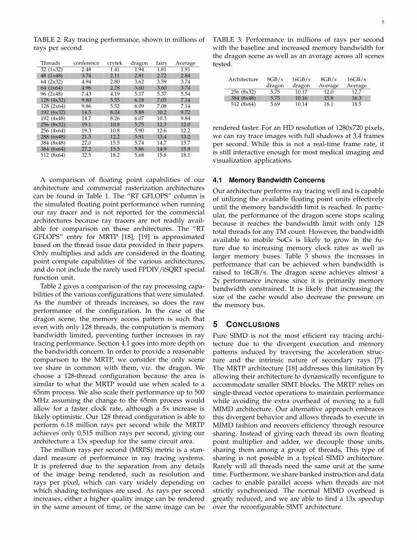
Conference282k triangles
(a)
Crytek Sponza262k triangles
(b)
Dragon871k triangles
(c)
Fairy174k triangles
(d)
Fig. 2: Test scenes used to evaluate performance
2.2 Research
Lohrmann [16] presents a method for performing raytracing on more traditional GPU-style architectures. Raytracing is expressed as vertex and fragment shader pro-grams that execute within the traditional rasterizationpipeline and operate on scene data stored within the tex-ture and buffer memories of the GPU. While Lohrmann’sapproach is a useful way to repurpose existing hardware,our architecture is designed to have the exact hardwareresources needed for ray tracing. In addition, Chang et.al. [17] find that bounding volume hierarchies (BVH)sare the most energy efficient acceleration structure onboth CPUs and GPUs. We similarly use a BVH for ouracceleration structure to reduce power consumption.
Kim et al. [18], [19] demonstrate their Mobile RayTracing Processor (MRTP), which is similar to mostSIMD targeted ray tracers in that they experience the dif-ficulty of dealing with the SIMT execution model. Theirapproach is to allow the architecture to dynamically re-configure a hybrid vector SIMD configuration with fewerdependent threads of execution. However, to ensure highvector utilization, the SIMD threads must be able to findopportunities to issue 3-wide vector operations. Whilethis dynamic reconfigurability is interesting, we employa MIMD design to allow for more thread flexibility. TheMRTP achieves a peak performance of 673K rays/secusing 16 mm2 in a 0.13 µm process running at 100MHz on a small scene. The MRTP only executes 103Krays/sec for the much larger dragon model, which isrepresentative of the size of modern scenes. Their workis the best point of comparison for mobile ray tracingaccelerators, hence Table 2 provides comparison withtheir best case performance, naively area and frequencyscaled to 65nm and 500 MHz. Anido et al. [20] alsosynthesize an architecture for interactive ray tracingin a 0.13 µm process that only consumes 0.125 mm2.However, their work tests only very simple scenes anddoes not use an acceleration structure, making it a poorpoint for comparison to the work presented here.
While our accelerator architecture targets the mobileSoC space, it has a lot in common with more general andhigher power architectures. TRaX [12], [13], Rigel [21],
Copernicus [22], etc. all take a basic block of threads,similar to the one presented here, and tile them on achip. The main difference is that these tiled architecturestarget a die area of around 200 mm2 and a relativelyhigh power budget, while this work targets a die area ofabout 10 mm2 with much less power consumption.
3 ARCHITECTURE AND METHODOLOGY
Our TP architecture is based on a simple, in-order integerthread execution model. Several of these thread TPs arethen grouped together in a TM to share a number offloating point execution units and banked instructionand data caches. The TM tile can be replicated to increasethe total compute power. Since the floating point unitsare shared within the architecture, we strive to find adesign point that is capable of achieving high utilizationof these shared units. To a great extent the floatingpoint utilization depends on the particular applicationexecuting on the system. In this work, we consider a raytracer that traces primary visibility as well as shadowrays.
To program our accelerator, we write a basic ray tracerin C/C++ and generate LLVM [23] intermediate code.We use a customized LLVM back end to emit codecompatible with our simple, RISC-like ISA. In orderto execute architecture specific instructions, we exposea few simple compiler intrinsics to the programmer.The single executable is then run on each thread inde-pendently. The primary form of communication amongthreads is a simple atomic increment instruction thateach thread uses to find a unique assignment. Globalmemory operations are managed by the programmerand the acceleration structure is built by the host CPUand made available in the accelerator’s memory space.
We simulate our architecture using a custom cycle-accurate system simulator in which we can instantiatea number of TPs and TMs as well as the associatedfunctional units, including caches and local memories.Conflicts for shared functional units are resolved in around robin fashion. This prevents starvation of anyindividual thread. Via cycle-accurate simulation, we can
4
accurately track functional unit utilization, memory us-age and other statistics related to the execution of ouraccelerator.
3.1 Architectural Details
Each TP consists of a simple, in-order, single-issue in-teger processor with 32 general purpose registers anda small 512 byte local memory. The local memory actsas an extended register file for local stack operations.We do not employ branch prediction and rely insteadon thread parallelism to achieve higher performanceand to keep the shared floating point units busy. Inevery configuration the FPU is shared by 8 TPs. We findempirically that this is sufficient since each TP spendsexecution on pointer chasing and waiting for memoryrequests to return which keeps it from issuing FPUinstructions on every cycle.
In addition to the FPUs that are shared by each TPcluster, we also have one special purpose floating pointdivide and inverse square root unit. Since this specialpurpose functional unit is rarely used, we use only oneof them per TM and for TMs comprising up to 64 TPs. Itshould also be noted that the FPDIV/iSQRT functionalunit has a latency of 8 cycles at 500 MHz. This is higherthan any of the other functional units in the accelerator,all of which have single cycle execution.
Each TM has a 4 kB, 16-bank instruction cache forevery 16 TPs allowing threads to issue in parallel aslong as they are fetching instructions from independentbanks. In practice our in-order threads have enoughexecution divergence that sharing this instruction cachedoes not have a large negative impact on performance.Sharing the cache banks and floating point units largelymitigates the die area overhead that a MIMD architecturewould normally have over a SIMD approach.
For each TM, we use a 16kB banked data cache thatcaches data from the global shared memory. We findthat one bank per 8 TP cluster is the appropriate choice.The global memory segment includes all of the scenedata, acceleration structure, and frame buffer. Becausethe thread assignment gives one pixel at a time to eachthread, we force all frame buffer writes to go around thedata cache thereby preventing pollution of the cache bylines which are write only.
We limit the off-chip bandwidth to 8 GB/s basedon the fact that upcoming mobile SoCs, such as theSamsung Exynos 5250 [24], achieve up to 12.8 GB/s ofmemory bandwidth with a 64 bit memory bus. We be-lieve 8 GB/s is a reasonable assumption for a compute-bound GPU in the near future because SoCs also sharethat memory bandwidth with other IP blocks. We notethat if the GPU and host CPU are both in memory boundcomputational segments, the shared bandwidth will im-pose performance restrictions. Section 4.1 considers afuture SoC with more available memory bandwidth.
For area and performance estimates, we use SynopsysDesignWare/Design Compiler [25] and a commercial
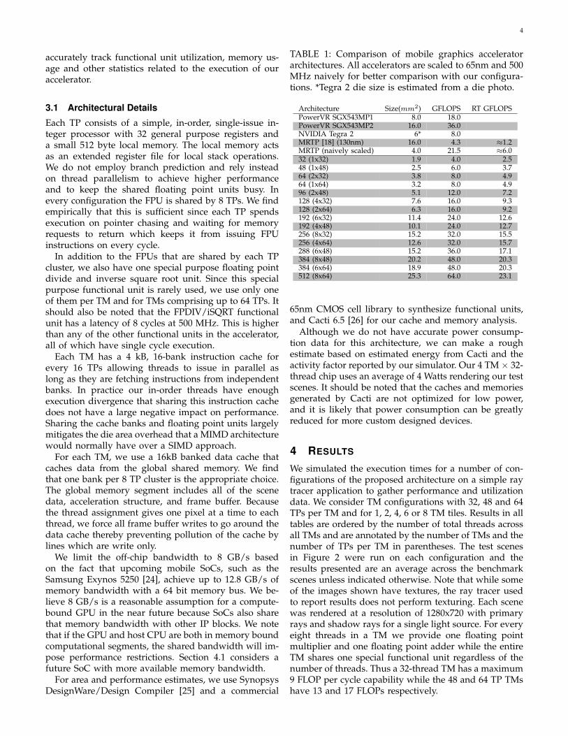
TABLE 1: Comparison of mobile graphics acceleratorarchitectures. All accelerators are scaled to 65nm and 500MHz naively for better comparison with our configura-tions. *Tegra 2 die size is estimated from a die photo.
Architecture Size(mm2) GFLOPS RT GFLOPSPowerVR SGX543MP1 8.0 18.0PowerVR SGX543MP2 16.0 36.0NVIDIA Tegra 2 6* 8.0MRTP [18] (130nm) 16.0 4.3 ≈1.2MRTP (naively scaled) 4.0 21.5 ≈6.032 (1x32) 1.9 4.0 2.548 (1x48) 2.5 6.0 3.764 (2x32) 3.8 8.0 4.964 (1x64) 3.2 8.0 4.996 (2x48) 5.1 12.0 7.2128 (4x32) 7.6 16.0 9.3128 (2x64) 6.3 16.0 9.2192 (6x32) 11.4 24.0 12.6192 (4x48) 10.1 24.0 12.7256 (8x32) 15.2 32.0 15.5256 (4x64) 12.6 32.0 15.7288 (6x48) 15.2 36.0 17.1384 (8x48) 20.2 48.0 20.3384 (6x64) 18.9 48.0 20.3512 (8x64) 25.3 64.0 23.1
65nm CMOS cell library to synthesize functional units,and Cacti 6.5 [26] for our cache and memory analysis.
Although we do not have accurate power consump-tion data for this architecture, we can make a roughestimate based on estimated energy from Cacti and theactivity factor reported by our simulator. Our 4 TM × 32-thread chip uses an average of 4 Watts rendering our testscenes. It should be noted that the caches and memoriesgenerated by Cacti are not optimized for low power,and it is likely that power consumption can be greatlyreduced for more custom designed devices.
4 RESULTS
We simulated the execution times for a number of con-figurations of the proposed architecture on a simple raytracer application to gather performance and utilizationdata. We consider TM configurations with 32, 48 and 64TPs per TM and for 1, 2, 4, 6 or 8 TM tiles. Results in alltables are ordered by the number of total threads acrossall TMs and are annotated by the number of TMs and thenumber of TPs per TM in parentheses. The test scenesin Figure 2 were run on each configuration and theresults presented are an average across the benchmarkscenes unless indicated otherwise. Note that while someof the images shown have textures, the ray tracer usedto report results does not perform texturing. Each scenewas rendered at a resolution of 1280x720 with primaryrays and shadow rays for a single light source. For everyeight threads in a TM we provide one floating pointmultiplier and one floating point adder while the entireTM shares one special functional unit regardless of thenumber of threads. Thus a 32-thread TM has a maximum9 FLOP per cycle capability while the 48 and 64 TP TMshave 13 and 17 FLOPs respectively.
5
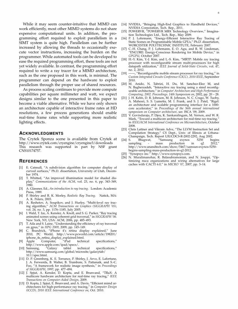
TABLE 2: Ray tracing performance, shown in millions ofrays per second.
Threads conference crytek dragon fairy Average32 (1x32) 2.48 1.41 1.94 1.81 1.9148 (1x48) 3.74 2.11 2.81 2.72 2.8464 (2x32) 4.94 2.80 3.62 3.59 3.7464 (1x64) 4.96 2.78 3.60 3.60 3.7496 (2x48) 7.43 4.19 5.17 5.37 5.54128 (4x32) 9.80 5.55 6.18 7.03 7.14128 (2x64) 9.86 5.52 6.09 7.08 7.14192 (6x32) 14.5 8.24 5.88 10.2 9.72192 (4x48) 14.7 8.26 6.07 10.3 9.84256 (8x32) 19.1 10.8 5.75 12.3 12.0256 (4x64) 19.3 10.8 5.90 12.6 12.2288 (6x48) 21.5 12.2 5.91 13.4 13.2384 (8x48) 27.0 15.5 5.74 14.7 15.7384 (6x64) 27.2 15.5 5.86 14.9 15.9512 (8x64) 32.5 18.2 5.68 15.8 18.1
A comparison of floating point capabilities of ourarchitecture and commercial rasterization architecturescan be found in Table 1. The “RT GFLOPS” column isthe simulated floating point performance when runningour ray tracer and is not reported for the commercialarchitectures because ray tracers are not readily avail-able for comparison on those architectures. The “RTGFLOPS” entry for MRTP [18], [19] is approximatedbased on the thread issue data provided in their papers.Only multiplies and adds are considered in the floatingpoint compute capabilities of the various architectures,and do not include the rarely used FPDIV/iSQRT specialfunction unit.
Table 2 gives a comparison of the ray processing capa-bilities of the various configurations that were simulated.As the number of threads increases, so does the rawperformance of the configuration. In the case of thedragon scene, the memory access pattern is such thateven with only 128 threads, the computation is memorybandwidth limited, preventing further increases in raytracing performance. Section 4.1 goes into more depth onthe bandwidth concern. In order to provide a reasonablecomparison to the MRTP, we consider the only scenewe share in common with them, viz. the dragon. Wechoose a 128-thread configuration because the area issimilar to what the MRTP would use when scaled to a65nm process. We also scale their performance up to 500MHz assuming the change to the 65nm process wouldallow for a faster clock rate, although a 5x increase islikely optimistic. Our 128 thread configuration is able toperform 6.18 million rays per second while the MRTPachieves only 0.515 million rays per second, giving ourarchitecture a 13x speedup for the same circuit area.
The million rays per second (MRPS) metric is a stan-dard measure of performance in ray tracing systems.It is preferred due to the separation from any detailsof the image being rendered, such as resolution andrays per pixel, which can vary widely depending onwhich shading techniques are used. As rays per secondincreases, either a higher quality image can be renderedin the same amount of time, or the same image can be
TABLE 3: Performance in millions of rays per secondwith the baseline and increased memory bandwidth forthe dragon scene as well as an average across all scenestested.
Architecture 8GB/s 16GB/s 8GB/s 16GB/sdragon dragon Average Average
256 (8x32) 5.75 10.17 12.0 12.7384 (8x48) 5.75 10.16 15.8 16.3512 (8x64) 5.69 10.14 18.1 18.5
rendered faster. For an HD resolution of 1280x720 pixels,we can ray trace images with full shadows at 3.4 framesper second. While this is not a real-time frame rate, itis still interactive enough for most medical imaging andvisualization applications.
4.1 Memory Bandwidth ConcernsOur architecture performs ray tracing well and is capableof utilizing the available floating point units effectivelyuntil the memory bandwidth limit is reached. In partic-ular, the performance of the dragon scene stops scalingbecause it reaches the bandwidth limit with only 128total threads for any TM count. However, the bandwidthavailable to mobile SoCs is likely to grow in the fu-ture due to increasing memory clock rates as well aslarger memory buses. Table 3 shows the increases inperformance that can be achieved when bandwidth israised to 16GB/s. The dragon scene achieves almost a2x performance increase since it is primarily memorybandwidth constrained. It is likely that increasing thesize of the cache would also decrease the pressure onthe memory bus.
5 CONCLUSIONS
Pure SIMD is not the most efficient ray tracing archi-tecture due to the divergent execution and memorypatterns induced by traversing the acceleration struc-ture and the intrinsic nature of secondary rays [7].The MRTP architecture [18] addresses this limitation byallowing their architecture to dynamically reconfigure toaccommodate smaller SIMT blocks. The MRTP relies onsingle-thread vector operations to maintain performancewhile avoiding the extra overhead of moving to a fullMIMD architecture. Our alternative approach embracesthis divergent behavior and allows threads to execute inMIMD fashion and recovers efficiency through resourcesharing. Instead of giving each thread its own floatingpoint multiplier and adder, we decouple those units,sharing them among a group of threads. This type ofsharing is not possible in a typical SIMD architecture.Rarely will all threads need the same unit at the sametime. Furthermore, we share banked instruction and datacaches to enable parallel access when threads are notstrictly synchronized. The normal MIMD overhead isgreatly reduced, and we are able to find a 13x speedupover the reconfigurable SIMT architecture.
6
While it may seem counter-intuitive that MIMD canwork efficiently, most other MIMD systems do not shareexpensive computational units. In addition, the pro-gramming effort required to exploit parallelism in aSIMT system is quite high. Parallelism can be furtherincreased by allowing the threads to occasionally exe-cute vector instructions, increasing the burden on theprogrammer. While automated tools can be developed toease the required programming effort, these tools are notyet widely available. In contrast, the programming effortrequired to write a ray tracer for a MIMD architecture,such as the one proposed in this work, is minimal. Theprogrammer can depend on the hardware to exploitparallelism through the proper use of shared resources.
As process scaling continues to provide more computecapabilities per square millimeter and watt, we expectdesigns similar to the one presented in this paper tobecome a viable alternative. While we have only shownan architecture capable of interactive frame rates at HDresolutions, a few process generations should enablereal-time frame rates while supporting more realisticlighting effects.
ACKNOWLEDGMENTSThe Crytek Sponza scene is available from Crytek athttp://www.crytek.com/cryengine/cryengine3/downloadsThis research was supported in part by NSF grantCNS10174757.
REFERENCES
[1] E. Catmull, “A subdivision algorithm for computer display ofcurved surfaces,” Ph.D. dissertation, University of Utah, Decem-ber 1974.
[2] T. Whitted, “An improved illumination model for shaded dis-play,” Communications of the ACM, vol. 23, no. 6, pp. 343–349,1980.
[3] A. Glassner, Ed., An introduction to ray tracing. London: AcademicPress, 1989.
[4] P. Shirley and R. K. Morley, Realistic Ray Tracing. Natick, MA:A. K. Peters, 2003.
[5] A. Reshetov, A. Soupikov, and J. Hurley, “Multi-level ray trac-ing algorithm,” ACM Transactions on Graphics (SIGGRAPH ’05),vol. 24, no. 3, pp. 1176–1185, July 2005.
[6] I. Wald, T. Ize, A. Kensler, A. Knoll, and S. G. Parker, “Ray tracinganimated scenes using coherent grid traversal,” in SIGGRAPH ’06.New York, NY, USA: ACM, 2006, pp. 485–493.
[7] T. Aila and S. Laine, “Understanding the efficiency of ray traversalon gpus,” in HPG 2009, 2009, pp. 145–149.
[8] C. Brandrick, “iPhone 4’s retina display explained,” June2010, PC World, http://www.pcworld.com/article/198201/iphone 4s retina display explained.html.
[9] Apple Computer, “iPad technical specifications,”http://www.apple.com/ipad/specs/.
[10] Samsung, “Galaxy tablet technical specifications,”http://www.samsung.com/global/microsite/galaxytab/10.1/spec.html.
[11] D. P. Greenberg, K. E. Torrance, P. Shirley, J. Arvo, E. Lafortune,J. A. Ferwerda, B. Walter, B. Trumbore, S. Pattanaik, and S.-C.Foo, “A framework for realistic image synthesis,” in Proceedingsof SIGGRAPH, 1997, pp. 477–494.
[12] J. Spjut, A. Kensler, D. Kopta, and E. Brunvand, “TRaX: Amulticore hardware architecture for real-time ray tracing,” IEEETransactions on Computer-Aided Design, 2009.
[13] D. Kopta, J. Spjut, E. Brunvand, and A. Davis, “Efficient mimd ar-chitectures for high-performance ray tracing,” in Computer Design(ICCD), 2010 IEEE International Conference on, Oct. 2010.
[14] NVIDIA, “Bringing High-End Graphics to Handheld Devices,”NVIDIA Corporation, Tech. Rep., 2011.
[15] POWERVR, “POWERVR MBX Technology Overview,” Imagina-tion Technologies Ltd., Tech. Rep., May 2009.
[16] P. J. Lohrmann, “Energy-Efficient Interactive Ray Tracing ofStatic Scenes on Programmable Mobile GPUs,” Ph.D. dissertation,WORCESTER POLYTECHNIC INSTITUTE, February 2007.
[17] C.-H. Chang, P. J. Lohrmann, E. O. Agu, and R. W. Lindeman,“ENCORE: Energy-Conscious Rendering for Mobile Device,” inGPGPU, October 2007.
[18] H.-Y. Kim, Y.-J. Kim, and L.-S. Kim, “MRTP: Mobile ray tracingprocessor with reconfigurable stream multi-processors for highdatapath utilization,” IEEE Journal of Solid-State Circuits, vol. 47,no. 2, 2012.
[19] ——, “Reconfigurable mobile stream processor for ray tracing,” inCustom Integrated Circuits Conference (CICC), 2010 IEEE, September2010.
[20] M. Anido, N. Tabrizi, H. Du, M. Sanchez-Elez M, andN. Bagherzadeh, “Interactive ray tracing using a simd reconfig-urable architecture,” in Computer Architecture and High PerformanceComputing, 2002. Proceedings. 14th Symposium on, 2002, pp. 20 – 28.
[21] J. H. Kelm, D. R. Johnson, M. R. Johnson, N. C. Crago, W. Tuohy,A. Mahesri, S. S. Lumetta, M. I. Frank, and S. J. Patel, “Rigel:an architecture and scalable programming interface for a 1000-core accelerator,” in Proceedings of the 36th annual internationalsymposium on Computer architecture, ser. ISCA ’09, 2009.
[22] V. Govindaraju, P. Djeu, K. Sankaralingam, M. Vernon, and W. R.Mark, “Toward a multicore architecture for real-time ray-tracing,”in IEEE/ACM International Conference on Microarchitecture, October2008.
[23] Chris Lattner and Vikram Adve, “The LLVM Instruction Set andCompilation Strategy,” CS Dept., Univ. of Illinois at Urbana-Champaign, Tech. Report UIUCDCS-R-2002-2292, Aug 2002.
[24] S. Bhagwat, “Samsung exynos 5250 beginssampling - mass production in q2 2012,”http://www.anandtech.com/show/5467/samsun-exynos-5250-begins-sampling-mass-production-in-q2-2012.
[25] “Synopsys inc.” http://www.synopsys.com.[26] N. Muralimanohar, R. Balasubramonian, and N. Jouppi, “Op-
timizing nuca organizations and wiring alternatives for largecaches with CACTI 6.0,” in MICRO ’07, 2007, pp. 3–14.