a methodology for simulation and verification of … · 2018-03-26 · machined surface,...
TRANSCRIPT

http://www.iaeme.com/IJMET/index.asp 450 [email protected]
International Journal of Mechanical Engineering and Technology (IJMET)
Volume 9, Issue 3, March 2018, pp. 450–461, Article ID: IJMET_09_03_045
Available online at http://www.iaeme.com/ijmet/issues.asp?JType=IJMET&VType=9&IType=3
ISSN Print: 0976-6340 and ISSN Online: 0976-6359
© IAEME Publication Scopus Indexed
A METHODOLOGY FOR SIMULATION AND
VERIFICATION OF TOOL PATH DATA FOR
3-AXIS AND 5-AXIS CNC MACHINING
Vishaldeep Singh, Hitesh Arora, Prashant K. Pandey and Rahul Wandra
Department of Mechanical Engineering, Lovely Professional University, Punjab, India
ABSTRACT
The main aim of using computer numerical control (CNC) technology for
machining is to achieve better quality of machined part and intern increase the
productivity of manufacturing operations. The NC toolpath data has the biggest effect
on the machining time and accuracy of the machined surface obtained under given
assumption that that we use an ideal machine tool and optimum cutting parameters
for machining a workpiece on a CNC machine tool. In this paper, an approach for the
simulation of tool path data for 3-axis and 5-axis machining has been introduced
using Boolean subtraction approach using SolidWorksTM CAD package. The part
modelling activities can be automated using macro in SolidWorksTM using
Application Programming Interface (API). Thus in the developed NC toolpath
simulator macro is developed for the verification of toolpath data for 3-axis and 5-
axis machining operations for metal removal with ball end mill, flat end mill and
toroidal end mill cutter shapes. The output from the simulated environment has been
saved in STL format for easy comparison with the original part model which was also
taken in STL format for the toolpath data generation. To verify the results generated
from the simulator two methods namely visual graphical inspection and by use of ray
tracing algorithm for determination of scallop height has been introduced. Two
sculptured freeform part shapes to be machined with flat end mill cutter in 3-axis and
5-axis machining has been used to validate the working of the simulator macro as well
as to verify the accuracy of input toolpath data.
Keywords: Simulation, 3-Axis and 5-Axis CNC Machining, Tool Path verification.
Cite this Article: Vishaldeep Singh, Hitesh Arora, Prashant K. Pandey and Rahul
Wandra, A Methodology for Simulation and Verification of Tool Path Data for 3-Axis
and 5-Axis CNC Machining, International Journal of Mechanical Engineering and
Technology, 9(3), 2018, pp. 450–461.
http://www.iaeme.com/IJMET/issues.asp?JType=IJMET&VType=9&IType=3
A Methodology for Simulation and Verification of Tool Path Data for 3-Axis and 5-Axis CNC
Machining
http://www.iaeme.com/IJMET/index.asp 451 [email protected]
1. INTRODUCTION
The engineering parts are described by the set of triangles which is known as Stereo
Lithography (STL) format. This format is most widely used for tool path planning, generating
tool path data. In machining operation using the triangulated model, a tool is made to pass
over the tool path identifying the tool position and orientation. There is a need to verify the
tool path generated from the triangulated model. There are different methods to verify tool
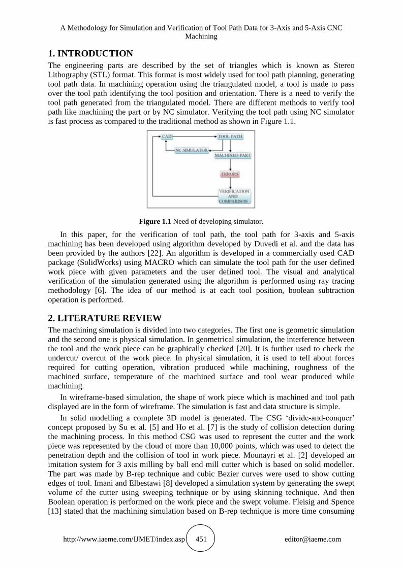
path like machining the part or by NC simulator. Verifying the tool path using NC simulator
is fast process as compared to the traditional method as shown in Figure 1.1.
Figure 1.1 Need of developing simulator.
In this paper, for the verification of tool path, the tool path for 3-axis and 5-axis
machining has been developed using algorithm developed by Duvedi et al. and the data has
been provided by the authors [22]. An algorithm is developed in a commercially used CAD
package (SolidWorks) using MACRO which can simulate the tool path for the user defined
work piece with given parameters and the user defined tool. The visual and analytical
verification of the simulation generated using the algorithm is performed using ray tracing
methodology [6]. The idea of our method is at each tool position, boolean subtraction
operation is performed.
2. LITERATURE REVIEW
The machining simulation is divided into two categories. The first one is geometric simulation
and the second one is physical simulation. In geometrical simulation, the interference between
the tool and the work piece can be graphically checked [20]. It is further used to check the
undercut/ overcut of the work piece. In physical simulation, it is used to tell about forces
required for cutting operation, vibration produced while machining, roughness of the
machined surface, temperature of the machined surface and tool wear produced while
machining.
In wireframe-based simulation, the shape of work piece which is machined and tool path
displayed are in the form of wireframe. The simulation is fast and data structure is simple.
In solid modelling a complete 3D model is generated. The CSG ‘divide-and-conquer’
concept proposed by Su et al. [5] and Ho et al. [7] is the study of collision detection during
the machining process. In this method CSG was used to represent the cutter and the work
piece was represented by the cloud of more than 10,000 points, which was used to detect the
penetration depth and the collision of tool in work piece. Mounayri et al. [2] developed an
imitation system for 3 axis milling by ball end mill cutter which is based on solid modeller.
The part was made by B-rep technique and cubic Bezier curves were used to show cutting
edges of tool. Imani and Elbestawi [8] developed a simulation system by generating the swept
volume of the cutter using sweeping technique or by using skinning technique. And then
Boolean operation is performed on the work piece and the swept volume. Fleisig and Spence
[13] stated that the machining simulation based on B-rep technique is more time consuming
Vishaldeep Singh, Hitesh Arora, Prashant K. Pandey and Rahul Wandra
http://www.iaeme.com/IJMET/index.asp 452 [email protected]
because of the increased part complexity. So to overcome this problem parallel processing
techniques was used. Yip-Hoi and Huang [14] used a semi cylinder to represent the tool and
the B-rep method is used to model the part. The solid modelling is used for the computation
of tool and work piece intersection geometry. The cutter engagement is identified for each
step of cutter during machining. Ferry and Yip-Hoi [17] extended Yip-Hoi and Huang [14]
work to 5-axis machining. The parallel slicing methodology is used. This method generates
the swept volume of the material removed by the cutter from work piece by Boolean
operation. Lee and Lee [11] a smoother rendering along with a screening ability of the Z-map
model in a 3-axis machining simulation. They used a local mesh method for the simulation
process. Lee and Ko [10] stated that to enhance the Z-map model, the inclined sampling
method was used. This technique is another version of anti-aliasing and it is used to increase
the efficiency of simulation algorithm along with mesh rendering in computer graphics. In
vector method, the facade of the part is represented by points. The direction vectors on these
points are perpendicular to the surface. A direction vector keeps on extending till it intersects
with another surface of the part or till it reaches the edge of the stock. A calculation of the
meeting point of each direction vector and tool movement is made in order to simulate the
machining process. If a vector intersects the envelope, then its length is reduced. In the
simulation, each direction vector represents the edge of grass growing from the surface and
the final length of the vector represents the amount of material removed at that point.
Karunakaran and Shringi [15] developed a machining simulation in which the formation of
the part and amendment in the part was done by octree method. Then for visual verification,
optimisation and animation of the machining simulation is done by B-rep method. Dyllong
and Grimm [16] stated that the nodes of octree are divided into eight nodes. These nodes are
compared with the cuboids. Each node contains the objects of the part. Every node of the
octree is checked whether it is fully or partially occupied or the node is empty. Lee and
Nestler [18] stated that the machining of the product is the material removal process with a
geometry defined cutting tool. In order to verify the tool path, the tool swept volume (SV) is
continually subtracted from the raw stock in the virtual environment during simulation.
Sullivan et al. [19] stated that the boundary representation (B-rep) is used by the solid
modelling based simulators in order to show case the milled work piece and in order to
perform the Boolean subtraction operation between a work piece and swept volume of the
tool between two positions. In simulation process generation of swept volume of tool is
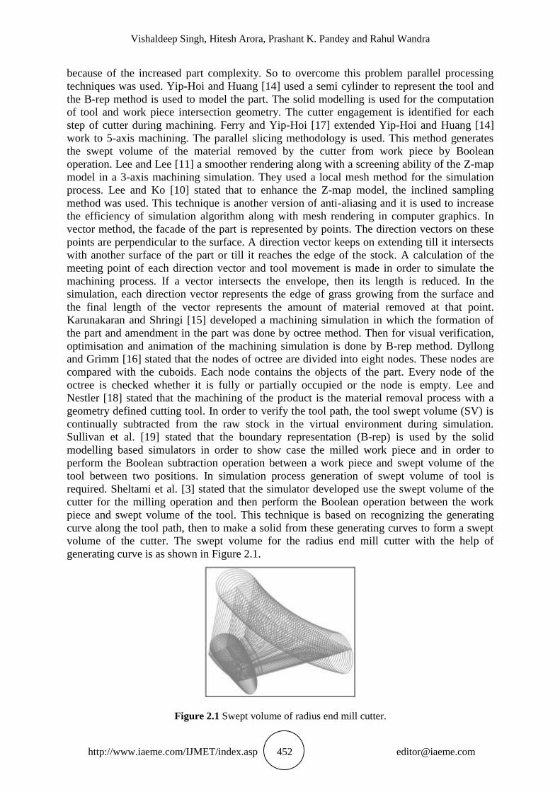
required. Sheltami et al. [3] stated that the simulator developed use the swept volume of the
cutter for the milling operation and then perform the Boolean operation between the work
piece and swept volume of the tool. This technique is based on recognizing the generating
curve along the tool path, then to make a solid from these generating curves to form a swept
volume of the cutter. The swept volume for the radius end mill cutter with the help of
generating curve is as shown in Figure 2.1.
Figure 2.1 Swept volume of radius end mill cutter.

A Methodology for Simulation and Verification of Tool Path Data for 3-Axis and 5-Axis CNC
Machining
http://www.iaeme.com/IJMET/index.asp 453 [email protected]
Roth et al. [4] stated that the tool swept volume is generated using the space curves. A
curve is identified on the tool surface for a given tool location. This is the impression of the
tool on the surface to be machined. The imprint space curve is identified for each tool location
and volume swept by the tool is generated. S. Mann and S. Bedi [12] extended the imprint
method for finding the swept volume for the surface swept by the tool for the machining of
the curved surfaces. The grazing points are calculated on surface of revolution and with the
help of these grazing points, grazing curve is generated for the cutter.
The verification of the simulated model is verified using ray tracing methodology. The
comparison is performed between the data generated from the ray tracing methodology of the
original STL model and the simulated STL model. D. Badouel [1] proposed the study to find
the intersection between the rays and triangles. In his study he used the barycentric co-
ordinates to find the intersection between the line and triangles. Segura and Feito [9] proposed
the algorithm to test the intersection of ray-triangles. They proposed the study in which no
errors were involved. They used the sign of triangles in the algorithm to find the intersection.
Where there is intersection the point of intersection can be calculated. The complex
calculations are not there in this algorithm, so the results computed are very much precise and
accurate.
3. PROPOSED IDEA FOR MACHINING SIMULATION FOR 3-AXIS
AND 5-AXIS MACHINING
In our work a computer program in visual basic for application is created in API SolidWorks
and it can be used for the automation to generate the model in SolidWorks. This automation is
used for the simulation of tool path in SolidWorks. The macro is created for the development
of simulator. The inputs required for the macros for NC simulator are: 1. Raw stock, 2. Tool
shape 3. Tool path, 4. Type of machining
For the simulation process the initial task is to select the type of machining for which the
simulation of the tool path has to be performed. Corresponding to that the tool path is taken in
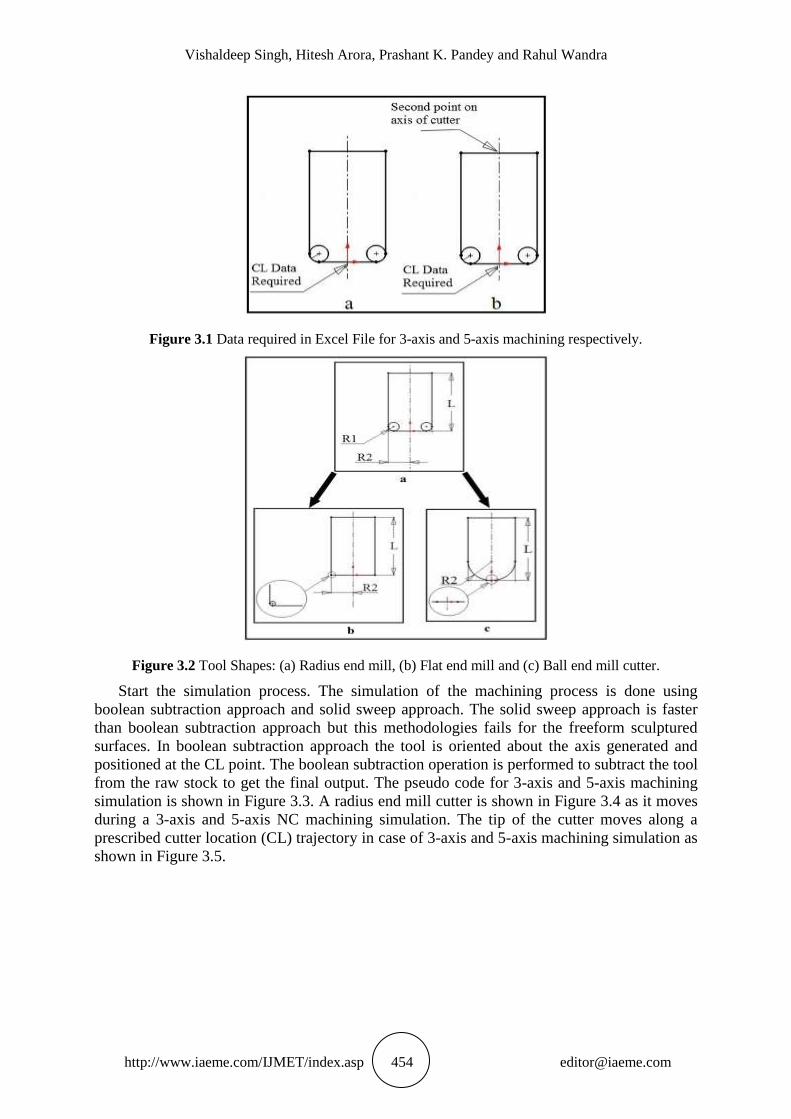
excel file. In case of 3-axis machining there is a need of cutter location data and for 5-axis
machining there is a need of second point on tool axis along with the cutter location. The tool
path data required for 3-axis and 5-axis machining is shown in Figure 3.1.
Then enter the parameters required for raw stock and generate raw stock. The raw stock is
generated in positive X and Y axis and machining will take place in negative Z direction.
After that select the type of tool that is required for machining process. Three types of tools
are mainly used for machining process are radius end mill cutter, flat end mill cutter and ball
end mill cutter. The flat end mill cutter and ball end mill cutter are derivative of radius end
mill cutter. In case of radius end mill cutter . Whereas in case of ball end mill cutter
and in case of flat end mill cutter is tool radius,
is fillet radius or radius of pseudo insert circle and is the length of tool. The tool shapes and
the zoom in sections of the variations of tool are shown in Figure 3.2. If the radius of pseudo
insert circle of radius end mill cutter is approaching zero, then flat end mill cutter is
considered and if it is equal to tool radius then ball end mill cutter is considered.
Vishaldeep Singh, Hitesh Arora, Prashant K. Pandey and Rahul Wandra
http://www.iaeme.com/IJMET/index.asp 454 [email protected]
Figure 3.1 Data required in Excel File for 3-axis and 5-axis machining respectively.
Figure 3.2 Tool Shapes: (a) Radius end mill, (b) Flat end mill and (c) Ball end mill cutter.
Start the simulation process. The simulation of the machining process is done using
boolean subtraction approach and solid sweep approach. The solid sweep approach is faster
than boolean subtraction approach but this methodologies fails for the freeform sculptured
surfaces. In boolean subtraction approach the tool is oriented about the axis generated and
positioned at the CL point. The boolean subtraction operation is performed to subtract the tool
from the raw stock to get the final output. The pseudo code for 3-axis and 5-axis machining
simulation is shown in Figure 3.3. A radius end mill cutter is shown in Figure 3.4 as it moves
during a 3-axis and 5-axis NC machining simulation. The tip of the cutter moves along a
prescribed cutter location (CL) trajectory in case of 3-axis and 5-axis machining simulation as
shown in Figure 3.5.

A Methodology for Simulation and Verification of Tool Path Data for 3-Axis and 5-Axis CNC
Machining
http://www.iaeme.com/IJMET/index.asp 455 [email protected]
Figure 3.3 Pseudo code for 3-axis and 5-axis machining simulation.
Figure 3.4 Radius end mill cutter moving through work piece (a) 3-axis, (b) 5-axis.
Figure 3.5 Radius end mill cutter moving through space along CL trajectory (a) 3-axis, (b) 5-axis.

Vishaldeep Singh, Hitesh Arora, Prashant K. Pandey and Rahul Wandra
http://www.iaeme.com/IJMET/index.asp 456 [email protected]
4. VERIFICATION
The most important thing is the verification of the tool path generated from the part and the
final output generated by simulation process from this tool path. The visual and analytical
verification of the tool path is possible [21]. The final output generated after the simulation
process is saved in the *.sldprt format and *.stl format for visual and analytical verification
respectively. The verification methodology is same for the 3-axis and 5-axis machining.
For the visual verification of the simulated part, compare the part formed by the
simulation process and the part from which the tool path has been generated. Open the new
assembly in SolidWorks. Insert the machined part at the default position in the assembly from
which the tool path has been generated. Similarly insert the final output generated after the
simulation process at the default position. The output thus can be used for visual verification
of the tool path.
For analytical verification STL file is generated for the simulated part. The ray tracing of
the simulated part is done. The data thus generated is compared with the ray traced data of
original part from which tool path is generated. The algorithm to find the comparison between
the two is as discussed.
1. Equation of line: ( ) ( )
2. Equation of triangle: ( ) ( ) ( )
3. At the intersection of line and triangular surface, equate the two equations.
( ) ( ) ( )
( ) ( ) ( )
The above equation can be written as: ( ) ( ) ( )
The above equation can be written in matrix form
[
] [ ] [ ]
Where
The above equation can be written as
[
] [ ] [
] (1)
1. Find and using equation (1).
2. If only then the solution is valid.
3. Repeat the above algorithm for all the triangles.
4. The ray traced data contains the co-ordinate values of each cutter location for the
machined part. Similarly find the co-ordinates for the simulated part. Find the
difference in the co-ordinates for each cutter location. If the difference is coming out
to be positive then there is an overcut and if the difference is coming out to be
negative then there is an undercut.
5. RESULTS
The actual tool path for the parts is generated from the STL file of the part. The tool path is
imported into the excel sheet. The input parameters used for simulation are given in Table 5.1.
The original part from which the tool part is generated is given in Figure 5.1.

A Methodology for Simulation and Verification of Tool Path Data for 3-Axis and 5-Axis CNC
Machining
http://www.iaeme.com/IJMET/index.asp 457 [email protected]
Table 5.1 Input parameters for machining simulation
Length of raw stock 25mm
Width of raw stock 50mm
Thickness of raw stock 40mm
Shape of tool Flat end mill tool
Radius of tool 3mm
Length of tool 10mm
The visual verification for the given part 1 and part 2 using 3-axis and 5-axis machining
simulation is shown in Figure 5.2.
Figure 5.1 Machined part 1 and part 2.
Figure 5.2 Visual verification of part 1 and part 2 (a) 3-axis and (b) 5-axis machining simulation.
The analytical verification for the two parts using the ray tracing methodology is
discussed here. The ray intersection data (x, y and z) are calculated in the feed forward/ tool
motion direction with the given increment and in the side step direction with the given
increment. The ray is traced from 0 to 4mm in x direction and from 10 to 30mm in y
direction. The ray tracing of the part with the given parameters is shown in Figure 5.3.

Vishaldeep Singh, Hitesh Arora, Prashant K. Pandey and Rahul Wandra
http://www.iaeme.com/IJMET/index.asp 458 [email protected]
Figure 5.3 Ray tracing of part.
Figure 5.4 Comparison of original machined part and simulated part (a) 3-axis and (b) 5-axis.
The 3D plots for 3-axis and 5-axis machining are formed which is used to represent the
undercut/ overcut of the simulated part. The yellow color represents the undercut; red color
represents the overcut and green color within the tolerance region of the simulated part. The
tolerance acceptance region for the simulation is taken from -0.1mm to +0.1mm. The feed
forward step increment is taken as 0.1mm and the side step increment is taken as 0.25mm.
The comparison is shown in Figure 5.4.
A Methodology for Simulation and Verification of Tool Path Data for 3-Axis and 5-Axis CNC
Machining
http://www.iaeme.com/IJMET/index.asp 459 [email protected]
These variations are because of that the tool path is generated for 1mm feed forward and
1mm side step distance for 3axis machining and 1mm feed forward and 3.5mm side step
distance for 5-axis machining. There are some stairs cases which will be generated from one
tool position to next tool position whereas in actual machining those steps are not there. In
this overcut values are there is primarily because of Boolean operation and left out stair steps
further because we have tried to compare the original STL model with the output of simulated
part again taken in STL format with 0.03mm chord height. So there can be some errors found
using ray tracing comparison at given x y location for z height of actual part and simulated
part. As the chord height for original part is 0.05mm and for the simulated part the chord
height is taken as 0.03mm. The errors in the tool positioning with respect to the original part
is of the magnitude ±0.05mm, they are expected. Similarly in ray tracing of simulated part the
errors in the tool positioning is of magnitude ±0.03mm is expected.
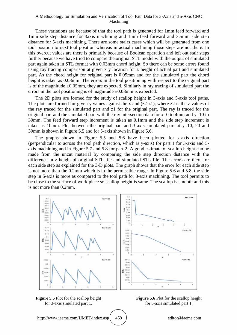
The 2D plots are formed for the study of scallop height in 3-axis and 5-axis tool paths.
The plots are formed for given y values against the x and (z2-z1), where z2 is the z values of
the ray traced for the simulated part and z1 for the original part. The ray is traced for the
original part and the simulated part with the ray intersection data for x=0 to 4mm and y=10 to
30mm. The feed forward step increment is taken as 0.1mm and the side step increment is
taken as 10mm. Plot between the original part and 3-axis simulated part at y=10, 20 and
30mm is shown in Figure 5.5 and for 5-axis shown in Figure 5.6.
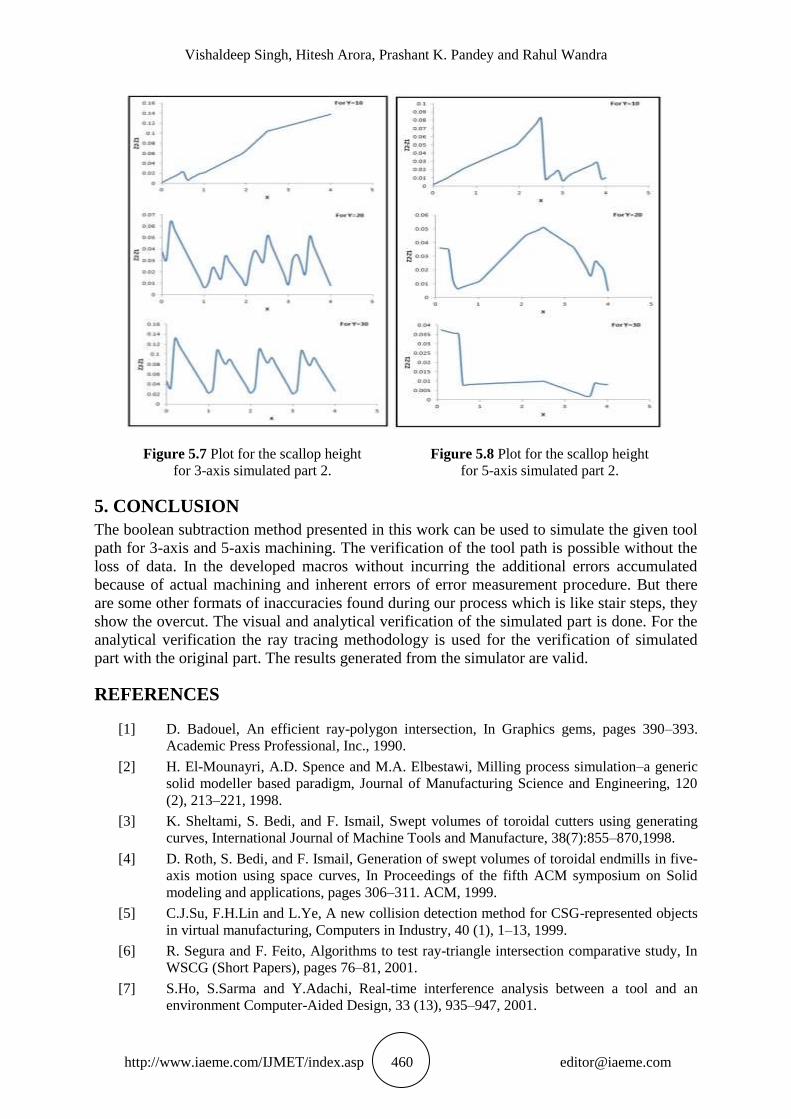
The graphs shown in Figure 5.5 and 5.6 have been plotted for x-axis direction
(perpendicular to across the tool path direction, which is y-axis) for part 1 for 3-axis and 5-
axis machining and in Figure 5.7 and 5.8 for part 2. A good estimate of scallop height can be
made from the uncut material by comparing the side step direction distance with the
difference in z height of original STL file and simulated STL file. The errors are there for
each side step as explained for the 3-D plots. The graph shows that the error for each side step
is not more than the 0.2mm which is in the permissible range. In Figure 5.6 and 5.8, the side
step in 5-axis is more as compared to the tool path for 3-axis machining. The tool permits to
be close to the surface of work piece so scallop height is same. The scallop is smooth and this
is not more than 0.2mm.
Figure 5.5 Plot for the scallop height Figure 5.6 Plot for the scallop height
for 3-axis simulated part 1. for 5-axis simulated part 1.
Vishaldeep Singh, Hitesh Arora, Prashant K. Pandey and Rahul Wandra
http://www.iaeme.com/IJMET/index.asp 460 [email protected]
Figure 5.7 Plot for the scallop height Figure 5.8 Plot for the scallop height
for 3-axis simulated part 2. for 5-axis simulated part 2.
5. CONCLUSION
The boolean subtraction method presented in this work can be used to simulate the given tool
path for 3-axis and 5-axis machining. The verification of the tool path is possible without the
loss of data. In the developed macros without incurring the additional errors accumulated
because of actual machining and inherent errors of error measurement procedure. But there
are some other formats of inaccuracies found during our process which is like stair steps, they
show the overcut. The visual and analytical verification of the simulated part is done. For the
analytical verification the ray tracing methodology is used for the verification of simulated
part with the original part. The results generated from the simulator are valid.
REFERENCES
[1] D. Badouel, An efficient ray-polygon intersection, In Graphics gems, pages 390–393.
Academic Press Professional, Inc., 1990.
[2] H. El-Mounayri, A.D. Spence and M.A. Elbestawi, Milling process simulation–a generic
solid modeller based paradigm, Journal of Manufacturing Science and Engineering, 120
(2), 213–221, 1998.
[3] K. Sheltami, S. Bedi, and F. Ismail, Swept volumes of toroidal cutters using generating
curves, International Journal of Machine Tools and Manufacture, 38(7):855–870,1998.
[4] D. Roth, S. Bedi, and F. Ismail, Generation of swept volumes of toroidal endmills in five-
axis motion using space curves, In Proceedings of the fifth ACM symposium on Solid
modeling and applications, pages 306–311. ACM, 1999.
[5] C.J.Su, F.H.Lin and L.Ye, A new collision detection method for CSG-represented objects
in virtual manufacturing, Computers in Industry, 40 (1), 1–13, 1999.
[6] R. Segura and F. Feito, Algorithms to test ray-triangle intersection comparative study, In
WSCG (Short Papers), pages 76–81, 2001.
[7] S.Ho, S.Sarma and Y.Adachi, Real-time interference analysis between a tool and an
environment Computer-Aided Design, 33 (13), 935–947, 2001.

A Methodology for Simulation and Verification of Tool Path Data for 3-Axis and 5-Axis CNC
Machining
http://www.iaeme.com/IJMET/index.asp 461 [email protected]
[8] B.M.Imani and M.A.Elbestawi, Geometric simulation of ball-end milling operations
Journal of Manufacturing Science and Engineering, 123 (2), 177–184, 2001.
[9] R. Segura and F. Feito, Algorithms to test ray-triangle intersection. Comparative study In
WSCG (Short Papers), pages 76–81, 2001.
[10] S.K.Lee and S.L.Ko, Development of simulation system for machining process using
enhanced Z map model, Journal of Materials Processing Technology, 130-131, 608-617,
2002.
[11] S.H.Lee, and S.K.Lee, Local mesh decimation for view-Independent three-axis NC
milling simulation, International Journal of Advanced Manufacturing Technology,19 (8),
pp.579–586, 2002.
[12] S. Mann and S. Bedi, Generalization of the imprint method to general surfaces of
revolution for NC machining Computer-aided design, 34(5): pp.373–378, 2002.
[13] R.V. Fleisig and A.D. Spence, Techniques for accelerating B-Rep based parallel
machining simulation Computer-Aided Design, 37 (12), pp.1229–1240, 2005.
[14] D. Yip-Hoi and X.M. Huang, Cutter/workpiece engagement feature extraction from solid
models for end milling Journal of Manufacturing Science and Engineering, 128 (1),
pp.249–260, 2006.
[15] K.P. Karunakaran and R. Shringi, Octree-to-BRep conversion for volumetric NC
simulation International Journal of Advanced Manufacturing Technology, 32 (1–2),
pp.116–131, 2007.
[16] E. Dyllong and C. Grimm, A reliable extended octree representation of CSG objects with
an adaptive subdivision depth Lecture Notes in Computer Science, 4967, 1341–1350,
2008.
[17] W. Ferry and D. Yip-Hoi, Cutter-workpiece engagement calculations by parallel slicing
for five-axis flank milling of jet engine impellers, Journal of Manufacturing Science and
Engineering, 130 (5), 051011.1–051011.12, 2008.
[18] S.W. Lee and A. Nestler, 5- Axis milling simulation using a swept volume via gauss map
In 16th WSCG International Conference in Central Europe on Computer Graphics,
Visualization and Computer Vision, Plzen, Czech Republic, 2008.
[19] A. Sullivan, H. Erdim, R.N. Perry, and S.F. Frisken, High accuracy NC milling simulation
using composite adaptively sampled distance fields Computer-Aided Design, 44(6):
pp.522–536, 2012.
[20] A. Hitesh et al., Studies on Temperature Variation and Angular Distortion in Submerged
Arc Welded Butt Joint Advanced Materials Research, Vol. 699, pp. 656-661, 2013.
[21] S. Mahipal, B. Manjinder, S. Rohit and A. Hitesh, Behaviour of aluminium alloy casting
with the variation of pouring temperature and permeability of sand International Journal of
Scientific and Engineering Research, vol. 4, no. 6, pp. 1497–1502, 2013.
[22] R. K. Duvedi, S. Bedi, A. Batish, and S. Mann, Scallop Height of 5-axis Machining of
Large Triangles with a Flat End Mill Annual International CAD conference 2014, Hong
Kong University of Science and Technology, China, June 2014.
[23] A. Sai Kumar, M. Ganesh and G Hima Bindu, Application of CNC Milling in
Manufacturing Turbine Blades. International Journal of Civil Engineering and
Technology, 8(5), 2017, pp. 801–808.
[24] Mufaddal A. Saifee and Dr. Usha S. Mehta. Design and Implementation of FPGA Based
G Code Compatible CNC Lathe Controller. International Journal of Electronics and
Communication Engineering & Technology, 7(1), 2016, pp. 75-86.
[25] Mufaddal A. Saifee and Dr. Usha S. Mehta, Design and Implementation of 3-Axis Linear
Interpolation Controller in FPGA for CNC Machines and Robotics, International Journal
of Advanced Research in Engineering and Technology (IJARET), Volume 5, Issue 9,
September (2014), pp. 52-62